KR20070107713A - A container - Google Patents
A container Download PDFInfo
- Publication number
- KR20070107713A KR20070107713A KR1020077019192A KR20077019192A KR20070107713A KR 20070107713 A KR20070107713 A KR 20070107713A KR 1020077019192 A KR1020077019192 A KR 1020077019192A KR 20077019192 A KR20077019192 A KR 20077019192A KR 20070107713 A KR20070107713 A KR 20070107713A
- Authority
- KR
- South Korea
- Prior art keywords
- cover
- closure
- alignment
- container
- base
- Prior art date
Links
Images


Classifications
-
- B—PERFORMING OPERATIONS; TRANSPORTING
- B65—CONVEYING; PACKING; STORING; HANDLING THIN OR FILAMENTARY MATERIAL
- B65D—CONTAINERS FOR STORAGE OR TRANSPORT OF ARTICLES OR MATERIALS, e.g. BAGS, BARRELS, BOTTLES, BOXES, CANS, CARTONS, CRATES, DRUMS, JARS, TANKS, HOPPERS, FORWARDING CONTAINERS; ACCESSORIES, CLOSURES, OR FITTINGS THEREFOR; PACKAGING ELEMENTS; PACKAGES
- B65D43/00—Lids or covers for rigid or semi-rigid containers
- B65D43/02—Removable lids or covers
- B65D43/0202—Removable lids or covers without integral tamper element
- B65D43/0204—Removable lids or covers without integral tamper element secured by snapping over beads or projections
- B65D43/021—Removable lids or covers without integral tamper element secured by snapping over beads or projections only on the inside, or a part turned to the inside, of the mouth
-
- B—PERFORMING OPERATIONS; TRANSPORTING
- B65—CONVEYING; PACKING; STORING; HANDLING THIN OR FILAMENTARY MATERIAL
- B65D—CONTAINERS FOR STORAGE OR TRANSPORT OF ARTICLES OR MATERIALS, e.g. BAGS, BARRELS, BOTTLES, BOXES, CANS, CARTONS, CRATES, DRUMS, JARS, TANKS, HOPPERS, FORWARDING CONTAINERS; ACCESSORIES, CLOSURES, OR FITTINGS THEREFOR; PACKAGING ELEMENTS; PACKAGES
- B65D21/00—Nestable, stackable or joinable containers; Containers of variable capacity
-
- B—PERFORMING OPERATIONS; TRANSPORTING
- B65—CONVEYING; PACKING; STORING; HANDLING THIN OR FILAMENTARY MATERIAL
- B65D—CONTAINERS FOR STORAGE OR TRANSPORT OF ARTICLES OR MATERIALS, e.g. BAGS, BARRELS, BOTTLES, BOXES, CANS, CARTONS, CRATES, DRUMS, JARS, TANKS, HOPPERS, FORWARDING CONTAINERS; ACCESSORIES, CLOSURES, OR FITTINGS THEREFOR; PACKAGING ELEMENTS; PACKAGES
- B65D2543/00—Lids or covers essentially for box-like containers
- B65D2543/00009—Details of lids or covers for rigid or semi-rigid containers
- B65D2543/00018—Overall construction of the lid
- B65D2543/00027—Stackable lids or covers
-
- B—PERFORMING OPERATIONS; TRANSPORTING
- B65—CONVEYING; PACKING; STORING; HANDLING THIN OR FILAMENTARY MATERIAL
- B65D—CONTAINERS FOR STORAGE OR TRANSPORT OF ARTICLES OR MATERIALS, e.g. BAGS, BARRELS, BOTTLES, BOXES, CANS, CARTONS, CRATES, DRUMS, JARS, TANKS, HOPPERS, FORWARDING CONTAINERS; ACCESSORIES, CLOSURES, OR FITTINGS THEREFOR; PACKAGING ELEMENTS; PACKAGES
- B65D2543/00—Lids or covers essentially for box-like containers
- B65D2543/00009—Details of lids or covers for rigid or semi-rigid containers
- B65D2543/00018—Overall construction of the lid
- B65D2543/00064—Shape of the outer periphery
- B65D2543/00074—Shape of the outer periphery curved
- B65D2543/00101—Shape of the outer periphery curved square-like or rectangular-like
-
- B—PERFORMING OPERATIONS; TRANSPORTING
- B65—CONVEYING; PACKING; STORING; HANDLING THIN OR FILAMENTARY MATERIAL
- B65D—CONTAINERS FOR STORAGE OR TRANSPORT OF ARTICLES OR MATERIALS, e.g. BAGS, BARRELS, BOTTLES, BOXES, CANS, CARTONS, CRATES, DRUMS, JARS, TANKS, HOPPERS, FORWARDING CONTAINERS; ACCESSORIES, CLOSURES, OR FITTINGS THEREFOR; PACKAGING ELEMENTS; PACKAGES
- B65D2543/00—Lids or covers essentially for box-like containers
- B65D2543/00009—Details of lids or covers for rigid or semi-rigid containers
- B65D2543/00018—Overall construction of the lid
- B65D2543/00259—Materials used
- B65D2543/00296—Plastic
-
- B—PERFORMING OPERATIONS; TRANSPORTING
- B65—CONVEYING; PACKING; STORING; HANDLING THIN OR FILAMENTARY MATERIAL
- B65D—CONTAINERS FOR STORAGE OR TRANSPORT OF ARTICLES OR MATERIALS, e.g. BAGS, BARRELS, BOTTLES, BOXES, CANS, CARTONS, CRATES, DRUMS, JARS, TANKS, HOPPERS, FORWARDING CONTAINERS; ACCESSORIES, CLOSURES, OR FITTINGS THEREFOR; PACKAGING ELEMENTS; PACKAGES
- B65D2543/00—Lids or covers essentially for box-like containers
- B65D2543/00009—Details of lids or covers for rigid or semi-rigid containers
- B65D2543/00342—Central part of the lid
- B65D2543/00398—Reinforcing ribs in the central part of the closure
- B65D2543/00416—Reinforcing ribs in the central part of the closure circular
-
- B—PERFORMING OPERATIONS; TRANSPORTING
- B65—CONVEYING; PACKING; STORING; HANDLING THIN OR FILAMENTARY MATERIAL
- B65D—CONTAINERS FOR STORAGE OR TRANSPORT OF ARTICLES OR MATERIALS, e.g. BAGS, BARRELS, BOTTLES, BOXES, CANS, CARTONS, CRATES, DRUMS, JARS, TANKS, HOPPERS, FORWARDING CONTAINERS; ACCESSORIES, CLOSURES, OR FITTINGS THEREFOR; PACKAGING ELEMENTS; PACKAGES
- B65D2543/00—Lids or covers essentially for box-like containers
- B65D2543/00009—Details of lids or covers for rigid or semi-rigid containers
- B65D2543/00444—Contact between the container and the lid
- B65D2543/00481—Contact between the container and the lid on the inside or the outside of the container
- B65D2543/0049—Contact between the container and the lid on the inside or the outside of the container on the inside, or a part turned to the inside of the mouth of the container
- B65D2543/00518—Skirt
-
- B—PERFORMING OPERATIONS; TRANSPORTING
- B65—CONVEYING; PACKING; STORING; HANDLING THIN OR FILAMENTARY MATERIAL
- B65D—CONTAINERS FOR STORAGE OR TRANSPORT OF ARTICLES OR MATERIALS, e.g. BAGS, BARRELS, BOTTLES, BOXES, CANS, CARTONS, CRATES, DRUMS, JARS, TANKS, HOPPERS, FORWARDING CONTAINERS; ACCESSORIES, CLOSURES, OR FITTINGS THEREFOR; PACKAGING ELEMENTS; PACKAGES
- B65D2543/00—Lids or covers essentially for box-like containers
- B65D2543/00009—Details of lids or covers for rigid or semi-rigid containers
- B65D2543/00444—Contact between the container and the lid
- B65D2543/00481—Contact between the container and the lid on the inside or the outside of the container
- B65D2543/00537—Contact between the container and the lid on the inside or the outside of the container on the outside, or a part turned to the outside of the mouth of the container
-
- B—PERFORMING OPERATIONS; TRANSPORTING
- B65—CONVEYING; PACKING; STORING; HANDLING THIN OR FILAMENTARY MATERIAL
- B65D—CONTAINERS FOR STORAGE OR TRANSPORT OF ARTICLES OR MATERIALS, e.g. BAGS, BARRELS, BOTTLES, BOXES, CANS, CARTONS, CRATES, DRUMS, JARS, TANKS, HOPPERS, FORWARDING CONTAINERS; ACCESSORIES, CLOSURES, OR FITTINGS THEREFOR; PACKAGING ELEMENTS; PACKAGES
- B65D2543/00—Lids or covers essentially for box-like containers
- B65D2543/00009—Details of lids or covers for rigid or semi-rigid containers
- B65D2543/00444—Contact between the container and the lid
- B65D2543/00481—Contact between the container and the lid on the inside or the outside of the container
- B65D2543/00555—Contact between the container and the lid on the inside or the outside of the container on both the inside and the outside
-
- B—PERFORMING OPERATIONS; TRANSPORTING
- B65—CONVEYING; PACKING; STORING; HANDLING THIN OR FILAMENTARY MATERIAL
- B65D—CONTAINERS FOR STORAGE OR TRANSPORT OF ARTICLES OR MATERIALS, e.g. BAGS, BARRELS, BOTTLES, BOXES, CANS, CARTONS, CRATES, DRUMS, JARS, TANKS, HOPPERS, FORWARDING CONTAINERS; ACCESSORIES, CLOSURES, OR FITTINGS THEREFOR; PACKAGING ELEMENTS; PACKAGES
- B65D2543/00—Lids or covers essentially for box-like containers
- B65D2543/00009—Details of lids or covers for rigid or semi-rigid containers
- B65D2543/00444—Contact between the container and the lid
- B65D2543/00592—Snapping means
- B65D2543/00601—Snapping means on the container
- B65D2543/00611—Profiles
- B65D2543/0062—Groove or hollow bead
-
- B—PERFORMING OPERATIONS; TRANSPORTING
- B65—CONVEYING; PACKING; STORING; HANDLING THIN OR FILAMENTARY MATERIAL
- B65D—CONTAINERS FOR STORAGE OR TRANSPORT OF ARTICLES OR MATERIALS, e.g. BAGS, BARRELS, BOTTLES, BOXES, CANS, CARTONS, CRATES, DRUMS, JARS, TANKS, HOPPERS, FORWARDING CONTAINERS; ACCESSORIES, CLOSURES, OR FITTINGS THEREFOR; PACKAGING ELEMENTS; PACKAGES
- B65D2543/00—Lids or covers essentially for box-like containers
- B65D2543/00009—Details of lids or covers for rigid or semi-rigid containers
- B65D2543/00444—Contact between the container and the lid
- B65D2543/00592—Snapping means
- B65D2543/00601—Snapping means on the container
- B65D2543/00675—Periphery concerned
- B65D2543/00685—Totality
-
- B—PERFORMING OPERATIONS; TRANSPORTING
- B65—CONVEYING; PACKING; STORING; HANDLING THIN OR FILAMENTARY MATERIAL
- B65D—CONTAINERS FOR STORAGE OR TRANSPORT OF ARTICLES OR MATERIALS, e.g. BAGS, BARRELS, BOTTLES, BOXES, CANS, CARTONS, CRATES, DRUMS, JARS, TANKS, HOPPERS, FORWARDING CONTAINERS; ACCESSORIES, CLOSURES, OR FITTINGS THEREFOR; PACKAGING ELEMENTS; PACKAGES
- B65D2543/00—Lids or covers essentially for box-like containers
- B65D2543/00009—Details of lids or covers for rigid or semi-rigid containers
- B65D2543/00444—Contact between the container and the lid
- B65D2543/00592—Snapping means
- B65D2543/00712—Snapping means on the lid
- B65D2543/00722—Profiles
- B65D2543/00731—Groove or hollow bead
-
- B—PERFORMING OPERATIONS; TRANSPORTING
- B65—CONVEYING; PACKING; STORING; HANDLING THIN OR FILAMENTARY MATERIAL
- B65D—CONTAINERS FOR STORAGE OR TRANSPORT OF ARTICLES OR MATERIALS, e.g. BAGS, BARRELS, BOTTLES, BOXES, CANS, CARTONS, CRATES, DRUMS, JARS, TANKS, HOPPERS, FORWARDING CONTAINERS; ACCESSORIES, CLOSURES, OR FITTINGS THEREFOR; PACKAGING ELEMENTS; PACKAGES
- B65D2543/00—Lids or covers essentially for box-like containers
- B65D2543/00009—Details of lids or covers for rigid or semi-rigid containers
- B65D2543/00444—Contact between the container and the lid
- B65D2543/00592—Snapping means
- B65D2543/00712—Snapping means on the lid
- B65D2543/00787—Periphery concerned
- B65D2543/00796—Totality
-
- B—PERFORMING OPERATIONS; TRANSPORTING
- B65—CONVEYING; PACKING; STORING; HANDLING THIN OR FILAMENTARY MATERIAL
- B65D—CONTAINERS FOR STORAGE OR TRANSPORT OF ARTICLES OR MATERIALS, e.g. BAGS, BARRELS, BOTTLES, BOXES, CANS, CARTONS, CRATES, DRUMS, JARS, TANKS, HOPPERS, FORWARDING CONTAINERS; ACCESSORIES, CLOSURES, OR FITTINGS THEREFOR; PACKAGING ELEMENTS; PACKAGES
- B65D2543/00—Lids or covers essentially for box-like containers
- B65D2543/00009—Details of lids or covers for rigid or semi-rigid containers
- B65D2543/00824—Means for facilitating removing of the closure
- B65D2543/00833—Integral tabs, tongues, handles or similar
- B65D2543/00842—Integral tabs, tongues, handles or similar outside of the lid
Abstract
Description
본 발명은 일반적으로 용기에 관한 것이고, 더 구체적으로는 그의 커버가 제1 위치에 적층될 때 함께 정렬되고 제2 위치에서 함께 로킹(lock)될 수 있는 용기에 관한 것이다.The present invention relates generally to a container, and more particularly to a container that can be aligned together and locked together in a second position when its cover is stacked in a first position.
강성의 열가소성 식품 용기가 일반적으로 공지되어 있다. 사용자는 종종 상이한 크기 및 형상의 다수의 이들 용기를 축적한다. 사용하지 않을 때, 용기는 종종 서랍에 아무렇게나 저장된다. 이 경우에, 미사용 용기는 상당한 공간을 차지하고, 정돈되지 않은 서랍에서 정합하는 베이스 및 커버를 찾는 것이 어려울 수 있다. 이를 회피하기 위해, 몇몇 사용자는 용기를 캐비넷 내에 적층한다. 용기의 베이스는 일반적으로 포개지고 따라서 무질서한 서랍에서 더 적은 공간을 차지하지만, 베이스와 커버를 정합하는 것이 여전히 어려울 수 있다. 게다가, 커버는 적층될 수 없고 커버는 무너지기 쉬울 수 있다. 용기가 식품을 저장하기 위해 사용중일 때, 용기는 종종 캐비넷 또는 냉장고에서 서로 상부에 적층된다. 이들 적층체는 위험할 수 있고, 이들의 낙하는 식품이 용기로부터 쏟아지게 할 수 있다. 다수의 사용자들은 비어 있거나 또는 사용중일 때에도 공간 효율적이고 덜 위험하고 구조적으로 더욱 견고하게 저장될 수 있는 용기를 원하고 있다.Rigid thermoplastic food containers are generally known. Users often accumulate a large number of these containers of different sizes and shapes. When not in use, containers are often stored randomly in drawers. In this case, the unused container takes up considerable space and it can be difficult to find a matching base and cover in an unordered drawer. To avoid this, some users stack containers in cabinets. The base of the container is generally superimposed and thus takes up less space in an disordered drawer, but it can still be difficult to mate the base and the cover. In addition, the cover cannot be laminated and the cover can be easily collapsed. When the containers are in use for storing food, the containers are often stacked on top of each other in a cabinet or refrigerator. These laminates can be dangerous and their dropping can cause food to pour out of the container. Many users want containers that can be stored space-efficient, less risky, and more structurally robust, even when empty or in use.
대규모 제조 중에, 커버는 개별 포장으로부터 분리되기 전에 벌크로 운반될 수 있다. 벌크 취급 중에, 제조업자들은 커버가 제조 작업 중에 일반적으로 작용하는 힘에 의해 발생되는 수직 및 측방향 운동에 저항하는데 충분히 안정적인 적층체를 형성할 수 있으면 바람직한 것을 발견할 수 있을 것이다.During large scale manufacturing, the cover can be transported in bulk before being separated from the individual package. During bulk handling, manufacturers will find it desirable if the cover can form a laminate that is sufficiently stable to resist the vertical and lateral movements generated by the forces generally acting during the manufacturing operation.
본 발명은 사용자 및 제조업자 모두에게 만족스러운 용기를 제공하는 것을 일반적인 목적으로 한다.It is a general object of the present invention to provide satisfactory containers for both users and manufacturers.
상기 점에 비추어, 본 발명은 그의 커버가 두 개의 상이한 방식으로 함께 적층될 수 있는 용기를 제공한다. 먼저, 커버는 "정렬" 적층 방식으로 적층될 수 있다. 정렬 적층 방식은 제조 중에 벌크 취급을 위한 충분한 구조적 견고성을 제공한다. 둘째로, 커버는 "로킹" 적층 방식으로 적층될 수 있다. 로킹 적층 방식은 정렬 적층 방식 보다 더욱 큰 구조적 견고성을 제공하고 미사용 커버를 저장할 때 유용하다.In view of the above, the present invention provides a container in which its cover can be laminated together in two different ways. First, the covers can be laminated in a "aligned" lamination manner. Aligned lamination provides sufficient structural robustness for bulk handling during manufacture. Secondly, the covers can be laminated in a "locking" lamination manner. Locking lamination provides greater structural robustness than alignment lamination and is useful when storing unused covers.
몇몇 실시예에서, 커버는 제1 폐쇄부, 결합부 및 정렬부를 구비한다. 베이스는 제2 폐쇄부를 구비한다. 커버의 제1 폐쇄부는 식품과 같은 품목을 위한 실질적으로 밀봉된 누출 방지 및 재밀봉 가능 저장 영역을 형성하도록 베이스의 제2 폐쇄부와 밀봉 결합 가능하다. 커버의 정렬부는 정렬된 커버 적층 방식을 형성하도록 제2 커버의 정렬부와 결합 가능하다. 커버의 결합부는 로킹된 커버 적층 방식을 형성하도록 제2 커버의 결합부와 결합 가능하다.In some embodiments, the cover has a first closure, coupling and alignment. The base has a second closure. The first closure of the cover is sealably engageable with the second closure of the base to form a substantially sealed leak-proof and resealable storage area for items such as food. The alignment portion of the cover is engageable with the alignment portion of the second cover to form an aligned cover stacking manner. The engaging portion of the cover is engageable with the engaging portion of the second cover to form a locked cover stacking manner.
커버 및 베이스는 사용자가 사용 후에 이들을 세척하거나 또는 이들의 구매 가격이 저렴하여 이들을 소모품으로서 사용할 목적으로 폐기할 수 있도록 비교적 얇은 두께의 플라스틱으로 경제적으로 구성될 수 있다. 용기는 예를 들면 통상의 열 성형 장치에 의해 용이하게 제조될 수 있다. 커버는 용기의 내용물의 만족스러운 가시성을 보장하도록 반투명 재료로 제조될 수 있다. 용기는 냉장고, 냉동고, 전자렌지 및 기계 식기 세척기 용도에 적합할 수 있다.Covers and bases can be economically constructed of relatively thin thickness plastic so that a user can clean them after use or their purchase price is low so that they can be discarded for use as a consumable. The container can be easily produced by, for example, a conventional thermoforming apparatus. The cover may be made of translucent material to ensure satisfactory visibility of the contents of the container. The container may be suitable for refrigerator, freezer, microwave and mechanical dishwasher applications.
본 발명의 특징은 첨부 도면과 함께 본 명세서에 제공된 상세한 설명의 숙독시에 당 기술 분야의 숙련자에게 명백해질 것이다.Features of the present invention will become apparent to those skilled in the art upon reading the detailed description provided herein with the accompanying drawings.
도 1은 본 발명의 실시예에 따른 커버 및 베이스를 갖는 용기의 등각도.1 is an isometric view of a container having a cover and a base according to an embodiment of the invention.
도 2는 도 1의 용기 커버의 등각도.2 is an isometric view of the container cover of FIG. 1.
도 3은 도 1의 용기 커버의 평면도.3 is a plan view of the container cover of FIG.
도 4는 도 1의 용기 베이스의 등각도.4 is an isometric view of the container base of FIG. 1.
도 5는 도 1의 용기 베이스의 평면도.5 is a plan view of the container base of FIG. 1.
도 6은 도 1의 용기의 측단면도.6 is a side cross-sectional view of the container of FIG. 1.
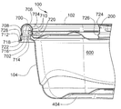
도 7은 도 6의 부분의 확대 상세도.7 is an enlarged detailed view of the portion of FIG. 6;
도 8은 도 7에 도시된 용기의 다른 실시예의 측단면도.8 is a side cross-sectional view of another embodiment of the container shown in FIG. 7.
도 9는 도 7에 도시된 용기의 다른 실시예의 측단면도.9 is a side cross-sectional view of another embodiment of the container shown in FIG. 7.
도 10은 두 개의 밀봉된 용기의 적층체의 측단면도.10 is a side cross-sectional view of a stack of two sealed containers.
도 11은 두 개의 로킹된 용기 커버와 함께 두 개의 포개진 용기 베이스를 적층한 적층체의 측단면도.FIG. 11 is a side cross-sectional view of a laminate stacking two nested container bases with two locked container covers. FIG.
도 12는 도 11의 적층체의 다른 실시예의 측단면도.12 is a side cross-sectional view of another embodiment of the laminate of FIG.
도 13은 하나의 로킹된 용기 커버 및 하나의 정렬된 커버와 함께 두 개의 포개진 용기 베이스를 적층한 적층체의 측단면도.FIG. 13 is a side cross-sectional view of a laminate stacking two nested container bases with one locked container cover and one aligned cover. FIG.
도 14는 도 13의 적층체의 다른 실시예의 측단면도.14 is a side cross-sectional view of another embodiment of the laminate of FIG. 13.
도 15는 용기 커버 및 베이스의 정렬 적층체의 측단면도.15 is a side cross-sectional view of the alignment stack of the container cover and the base.
도 16은 두 개의 정렬된 용기 커버와 함께 두 개의 포개진 용기 베이스를 적층한 적층체의 측단면도.FIG. 16 is a side cross-sectional view of a laminate stacking two nested container bases with two aligned container covers. FIG.
도 17은 하나의 정렬된 용기 커버 및 하나의 로킹된 용기 커버와 함께 두 개의 포개진 용기 베이스를 적층한 적층체의 측단면도.FIG. 17 is a side cross-sectional view of a laminate stack of two nested container bases with one aligned container cover and one locked container cover. FIG.
도 18은 두 개의 용기 커버의 로킹된 적층체의 측단면도.18 is a side cross-sectional view of a locked stack of two container covers.
도 19는 도 18의 부분의 확대 상세도.19 is an enlarged detail of the portion of FIG. 18;
도 20은 두 개의 용기 커버의 정렬된 적층체의 측단면도.20 is a cross-sectional side view of an aligned stack of two container covers.
도 21은 도 20의 부분의 확대 상세도.21 is an enlarged detail of the portion of FIG. 20;
도 22는 본 발명에 따른 용기를 제조하기 위한 예시적인 제조 방법의 프로세스 흐름도.22 is a process flow diagram of an exemplary manufacturing method for producing a container according to the present invention.
도 23은 본 발명에 따른 용기를 제조하기 위한 다른 예시적인 제조 방법의 프로세스 흐름도.23 is a process flow diagram of another exemplary manufacturing method for producing a container according to the present invention.
유사한 참조번호가 유사한 요소를 나타내는 도면을 참조하면, 본 발명의 제1 실시예가 도 1 내지 도 5에 도시되어 있다. 용기(100)는 베이스(104)에 밀봉 결합 된 가요성 커버(102)를 구비한다. 도 1 내지 도 5의 예에서, 용기(100)는 라운딩된 코너를 갖는 실질적으로 정사각형으로서 도시되어 있다. 본 발명의 다른 실시예에서, 용기는 직사각형, 원형 또는 타원형과 같은 다른 형상을 갖는다.Referring to the drawings, wherein like reference numerals refer to like elements, a first embodiment of the present invention is shown in FIGS. The
용기 커버(102)는 용기 베이스(104)로부터 커버(102)의 제거를 용이하게 하기 위한 적어도 하나의 파지 탭(106)을 구비할 수 있다. 몇몇 실시예에서, 파지 탭(106)은 탭(106) 상의 사용자의 파지를 향상시키도록 하나 이상의 교차 리브 또는 질감형성 표면을 구비한다.The
도 2 및 도 3에 도시된 용기 커버(102)는 커버(102)의 로킹된 적층체를 형성하도록 제2 커버(102)의 결합부(200)와 커버(102)가 결합하는 것을 허용하는 결합부(200)를 구비한다. 이 로킹 특징은 커버의 최종 적층체를 구조적으로 더 강성이 되게 하고 따라서 전형적인 비상호로킹식 커버의 적층체보다 덜 위험하게 한다.The
도 2 및 도 3의 결합부(200)는 원형으로서 도시되었지만, 용기(100)의 형상 자체와 마찬가지로 다른 형상도 가능하다. 몇몇 실시예에서, 결합부(200)의 표준 형상 및 구조가 다양한 형상 및 크기의 커버(102)와 함께 사용된다. 이는 상이한 유형의 커버(102)가 로킹 적층체에서 함께 저장되게 함으로써 저장 가요성을 향상시킨다. 결합부(200)는 또한 커버(102)의 중간선(304, 306)이 도 3에 도시된 바와 같이 교차하는 지점(302)에 수직인 축 둘레에서 회전을 한정하는 회전 정렬을 커버(102)의 적층 또는 로킹 적층체에 제공하는 요소를 포함하거나 또는 형상을 갖도록 선택될 수 있다. 예를 들면, 본질적으로 결합에 앞서 정렬을 요구하거나 결합부를 연결하는 프로세스 중에 자체 정렬될 수 있는 형상은 삼각형, 정사각형, 직사 각형 또는 다중 화판 형상과 같은 선형 또는 곡선형 측면, 정점 또는 로브(lobe)를 갖는 형상일 수 있다. 부가적으로, 커버는 결합부의 연결에 앞서 정렬을 요구하는 결합부 상의 또는 그 둘레의 하나 이상의 요소 또는 결합부를 연결하는 프로세스 중에 자체 정렬될 수 있는 요소를 가질 수 있다.Although the
용기 커버(102)는 결합부(200)의 상부에 도 3에 도시된 중앙 구역(300)을 가질 수 있다. 중앙 구역(300)은 제조업자의 마크와 같은 양각된 심벌을 포함할 수 있거나 사용자가 날짜 또는 사용자의 성명과 같은 정보를 기록하거나 라벨을 부착하는 것을 허용할 수 있다. 중앙 구역(300)이 기록 가능 영역을 포함할 때, 이 영역은 필기구로부터 대조되는 색상을 수용할 수 있는 불투명 영역일 수 있다. 기록 가능 영역은 용기 커버(102)용 재료에 합체될 수 있거나 인쇄에 의해 재료에 도포될 수 있다.The
도 1 내지 도 3의 용기 커버(102)는 용기 베이스(104)보다 얇은 벽 두께를 갖고 구성될 수 있다. 커버(102)는 임의의 적합한 플라스틱으로 제조될 수 있고 열 성형과 같은 임의의 적합한 기술에 의해 제조될 수 있다. 일 실시예에서, 커버(102)는 폴리프로필렌으로 형성될 수 있다. 열 성형 프로세스에 기인하여, 커버(102)의 벽 두께는 변경될 수 있다. 더 얇은 용기 커버(102)는 재료 비용을 감소시키고 용기 베이스(104)로부터의 제거 및 결합을 더 용이하게 수용하도록 가요성을 증가시킨다. 커버(102)는 일반적인 냉장고 온도 중에서도 적절한 밀봉을 위한 적절한 가요성을 유지할 수 있다.The
도 4 및 도 5의 용기 베이스(104)는 저부(400) 및 저부(400)의 주변부로부터 연장하는 측벽을 구비한다. 저부(400)는 용기(100)가 함께 적층될 때 용기 커버(102)의 결합부(200)를 수용하도록 하는 융기된 하부 섹션(404)을 구비한다. 이 특징은 이하에 더 논의되고 예시된다. 도 3의 결합부가 중앙 구역(300)을 포함할 수 있는 것과 같이, 제조업자의 상표 또는 사용자 정보를 위한 유사한 구역이 베이스(104)의 융기부(404)에 포함될 수 있다.The
도 1, 도 4 및 도 5의 용기 베이스는 상부 선반 식기 세척 및 전자렌지 조리의 열을 변형되지 않고 견디어 낼 수 있도록 충분한 두께를 갖는 임의의 적합한 플라스틱으로 제조될 수 있다. 또한 고온 식품을 적재하면서 상승 중에 튼튼하게 유지되어야 한다. 베이스(104)는 임의의 적합한 플라스틱으로 제조될 수 있고 공동 압출, 적층, 사출 성형, 열 성형 또는 오버몰딩(overmolding)과 같은 임의의 적합한 기술에 의해 제조될 수 있다. 일 실시예에서, 용기 베이스(104)는 폴리프로필렌으로 형성된다. 용기 베이스(104)의 벽 두께는 제조 프로세스에 기인하여 변경될 수 있다.The container bases of FIGS. 1, 4 and 5 may be made of any suitable plastic having a sufficient thickness to withstand the heat of the upper shelf dish washing and microwave cooking without deformation. It should also be kept strong during ascent while loading hot food. The base 104 can be made of any suitable plastic and can be made by any suitable technique, such as co-extrusion, lamination, injection molding, thermoforming or overmolding. In one embodiment, the
도 6 내지 도 9는 그의 커버(102)가 그의 베이스(104)와 밀봉 결합되는 용기(100)의 실시예를 도시한다. 도 6은 밀봉된 저장실(600)을 형성하도록 베이스(104)와 협동하는 커버(102)를 도시한다. 커버(102)는 밀봉시에 사용자가 용기(100) 내에 진공을 생성하도록 충분히 가요성일 수 있다. 진공을 생성하기 위해, 사용자는 예를 들면 용기(100)의 폐쇄 중에 커버(102)를 가압한다. 커버(102)의 재료의 탄성에 의해 커버(102)에 부여된 복귀력이 그의 수직 위치로 커버(102)를 압박 복귀시켜 이에 의해 진공을 생성한다. 그의 베이스(104)와 커버(102)의 적합한 밀봉 결합을 용이하게 하기 위해, 사용자는 용기 커버(102)의 결합부(200)에만 하향력을 재량껏 인가할 수 있다. 결합부(200)는 베이스(104)로의 밀봉 중에 커버(102)의 제1 폐쇄부(700)에 힘을 수용하고 분배하도록 위치된다. 결합부(200)는 또한 커버(102)를 파지하기 위한 적합한 핸들로서 작용할 수 있다.6-9 illustrate an embodiment of a
도 6 내지 도 9의 실시예에서, 용기(100)는 설명되는 바와 같이 내부 및 외부 밀봉부 모두를 포함하는 로킹 림 디자인을 사용한다. 본 발명은 외부 폐쇄부 및/또는 내부 폐쇄부를 포함하는 다양한 폐쇄 디자인으로 실시될 수 있다.In the embodiment of FIGS. 6-9, the
도 7은 용기(100)의 베이스(104)와 커버(102)를 결합하는데 사용되는 폐쇄부의 실시예를 도시한다. 커버(102)는 융기된 로킹 링의 형태의 제1 폐쇄부(700)를 구비한다. 커버(102)의 제1 폐쇄부(700)는 누출 방지 재밀봉 가능 폐쇄부를 제공하도록 베이스(104)의 제2 폐쇄부(702)와 결합될 수 있다.7 illustrates an embodiment of a closure used to join the
제1 폐쇄부(700)는 내부벽(704), 보유 비드(706) 및 외부벽(708)을 구비한다. 내부벽(704), 보유 비드(706) 및 외부벽(708)은 커버(102)의 하부면의 부분인 제1 밀봉면을 형성한다. 제1 폐쇄부(700)는 하나 이상의 로킹 리지(locking ridge;710)를 포함할 수 있다. 외부벽(708)은 보유 비드(706)와 플랜지(712) 사이로 연장한다. 플랜지(712)는 베이스(104)로부터의 커버(102)의 제거를 용이하게 하기 위해 적합한 파지면을 제공할 수 있다.The
도 7에 도시된 바와 같이, 베이스(104)의 제2 폐쇄부(702)는 베이스(104)의 측벽의 상부 에지로부터 연장하는 융기된 로킹 링이다. 제2 폐쇄부(702)는 내부벽(714), 보유 비드(716) 및 외부벽(718)을 포함한다. 내부벽(714), 보유 비 드(716) 및 외부벽(718)은 베이스(104)의 상부면의 부분인 제2 밀봉면을 형성한다. 제2 폐쇄부(702)는 하나 이상의 로킹 리지(720)를 포함할 수 있다. 외부벽(718)은 보유 비드(716)와 플랜지(7222) 사이로 연장한다. 플랜지(722)는 베이스(104)로부터의 커버(102)의 제거를 용이하게 하기 위한 적합한 파지면을 제공할 수 있다.As shown in FIG. 7, the
제1 및 제2 폐쇄부(700, 702)는 그 사이에 간섭 끼워맞춤을 형성하도록 크기가 약간 상이하도록 구성될 수 있다. 제1 및 제2 폐쇄부(700, 702) 사이의 간섭 끼워맞춤은 폐쇄부 사이의 밀봉 결합을 제공할 수 있다. 그 결과, 두 개의 부분이 결합될 때, 포지티브 밀봉(positive seal)이 커버(102) 및 베이스(104)의 주위 둘레에서 제1 및 제2 밀봉면 사이에 형성될 수 있다.The first and
제1 및 제2 폐쇄부(700, 702)의 결합은 용기가 견고하게 폐쇄된 것을 지시하는 청취 가능한 "스냅"에 의해 수반될 수 있다.The combination of the first and
도 7의 예에서, 커버(102)의 제1 폐쇄부(700)의 내부벽(704)은 결합부(200)로 연장한다. 이 결합부(200)는 상부 돌기(724) 및 하부 돌기(726)를 구비한다.In the example of FIG. 7, the inner wall 704 of the
도 7의 실시예에서, 커버(102)는 제1 폐쇄부(700)의 외부벽(708) 상에 리지(728)를 구비한다. 도 8은 이 리지가 없는 다른 실시예를 나타낸다. 일반적으로, 도 6 내지 도 9에 도시된 제1 및 제2 폐쇄부(700, 702) 및 결합부(200)는 단지 예시일 뿐이고, 다수의 다른 유형의 폐쇄 및 결합부가 본 발명에 사용될 수 있다. 예를 들면, 결합부(200)는 상보형 로킹 링을 구비할 수 있다. 이들 및 다수의 다른 유형의 폐쇄 및 결합부는 당 기술 분야에 공지되어 있기 때문에, 이들은 여기에 상세하게 논의되지는 않을 것이다.In the embodiment of FIG. 7, the
도 9는 커버의 다른 실시예를 도시한다. 도 9의 커버(102)는 제1 폐쇄부(700)의 외부벽(708) 상에 배치된 정렬 리지(900)를 구비한다. 이 정렬 리지(900)는 이하에 상세하게 논의된다.9 shows another embodiment of a cover. The
도 10에서, 밀봉된 용기(100)는 제2 밀봉된 용기(1000)의 상부에 위치한다. 상부 용기(100)의 베이스(104)의 융기된 하부 섹션(404)은 하부 용기(1000)의 커버(1002)의 결합부(200)를 수용한다.In FIG. 10, the sealed
도 11 및 도 12는 용기가 저장 중일 때 본 발명의 실시예의 유용성을 도시한다. 도면에서, 두 개의 포개진 용기 베이스(104, 1100)의 적층체는 커버(102, 1102)의 로킹된 적층체에 결합된다. 하부 커버(102)는 구조적으로 강성의 적층체를 형성하도록 상부 베이스(104)와 밀봉 결합된다.11 and 12 illustrate the usefulness of embodiments of the present invention when the container is being stored. In the figure, a stack of two nested
도 11 및 도 12의 실시예에서, 두 개의 커버(102, 1102)는 이들의 결합부(200)에 의해 함께 로킹된다. 도 7과 관련하여 설명된 바와 같이, 결합부(200)는 상부 돌기(724) 및 하부 돌기(726)를 각각 포함할 수 있다. 각각의 돌기(724, 726)는 일 측면에서 볼록형이고 다른 측면에서 오목형이다. 상부 커버(1102)의 하부 돌기(726)는 하부 커버(102)의 상부 돌기에 끼워져서 이를 수용하고, 따라서 커버(102, 1102)를 함께 로킹한다. 이 방식으로, 커버(102, 1102)는 함께 유지되어 구조적으로 안정한 커버 적층체를 형성한다. 결합부의 다른 실시예는 결합을 가능하게 하도록 이하의 형태(feature), 즉 볼록부 또는 리브, 오목부 또는 리브, 선형 또는 곡선형 언더컷(undercut), 개별 스냅 요소 또는 버튼, 간섭 끼워맞춤부, 질감 형성면 또는 결합의 지점 또는 그 둘레에서 표면 마찰 또는 점착성을 변형하는 요 소 중 하나 이상을 포함할 수 있다. 로킹 상태를 생성하는 결합 영역은 결합부에 대해 연속적이거나 결합부에 대해 불연속적으로 분할된다. 몇몇 실시예에서, 커버를 연결하는데 요구되는 힘은 커버를 분리하는데 요구되는 힘과는 실질적으로 상이할 수 있다. 예를 들면, 커버를 연결하기 위해 요구되는 힘이 커버를 분리하는데 요구되는 힘보다 작은 것이 제조 중에 이점이 있을 수 있다. 그 결과, 커버는 제조 중에 연결이 비교적 용이하고, 여전히 이들은 제조 프로세스 중에 견고하게 로킹되고 바람직하지 않게 분리되지 않을 것이다. 이를 성취하기 위해, 결합부 상의 돌기가 설계될 수 있고, 여기서 소정의 돌기에 대해 상부 돌기 에지는 점진적인 테이퍼를 포함하는 반면 하부 돌기 에지는 더 돌출한 형상을 포함한다. 예를 들면, 일 실시예에서, 돌기의 형상은 결합 중에 약간의 저항을 부여할 수 있는 갈고리(barb)의 상부 에지 상에서 점진적인 테이퍼를 갖고 분리 중에 비교적 높은 저항을 부여할 수 있는 갈고리의 하부 에지 상의 돌출 형상을 갖는 갈고리가 형성된 후크와 유사할 수 있다. 역으로, 사용자가 만족스러운 로킹 완전성에 동일하다고 지각할 수 있기 때문에 커버를 연결하도록 인가될 필요가 있는 힘은 커버를 분리하는데 요구되는 힘보다 크고 반면에 약한 연결력은 커버 적층체가 예측된 구조적인 이점을 보장하는데 요구되는 완전성이 결여되었다고 지각하도록 사용자를 유도할 수 있도록 결합부를 설계하는 것이 유리할 수 있다. 따라서, 높은 연결력은 지각된 이점을 제공하고, 또한 낮은 분리력은 사용자가 커버의 분리 중에 부적당하게 애쓰는 것을 요구하지 않는다. 이를 성취하기 위해, 결합부 상의 돌기가 설계될 수 있고, 여기서 소정의 돌기에 대해 상부 돌기 에지는 돌출 형상을 포함하는 반면 에 하부 돌기 에지는 더 점진적인 테이퍼를 포함한다. 예를 들면, 일 실시예에서, 돌기의 형상은 결합 중에 비교적 높은 저항을 부여할 수 있는 갈고리의 상부 에지 상의 돌출 형상을 갖고 분리 중에 적은 저항을 부여할 수 있는 갈고리의 하부 에지 상의 점진적인 테이퍼를 갖는 반전된 갈고리일 수 있다. 더욱이, 사용자가 커버를 함께 로킹하도록 일반적인 커버 평면에 수직인 방향으로 정렬된 커버에 힘을 인가하는 프로세스 중에, 결합부는 로킹시에 촉각 또는 청취 가능한 피드백을 제공할 수 있다. 이 방식으로 사용자는 커버가 연결되고 다른 부가의 힘이 인가될 필요가 없는 것을 감지한다.In the embodiment of FIGS. 11 and 12, the two
용기 베이스(104, 1100)는 도 11 및 도 12에서 포개져 있지만 함께 로킹되지는 않은 것으로 도시되어 있다. 다수의 적용에서, 이들을 함께 로킹하지 않고 용기 베이스를 포개는 것은 베이스의 적층체에 충분한 구조적 강성을 제공한다. 그러나, 베이스 자체에 본 발명의 기술을 적용하고 따라서 베이스를 함께 로킹하기 위한 기구를 제공하는 것이 가능하다. 커버를 함께 로킹하기 위해 또는 베이스에 커버를 로킹하기 위해 이용 가능한 동일한 유형의 폐쇄 및 결합부가 베이스와 함께 로킹하도록 적용될 수 있다.The container bases 104, 1100 are shown stacked in FIGS. 11 and 12 but not locked together. In many applications, nesting container bases without locking them together provides sufficient structural rigidity to the stack of bases. However, it is possible to apply the technique of the invention to the base itself and thus to provide a mechanism for locking the base together. The same type of closures and engagements available for locking the cover together or for locking the cover to the base may be applied to lock with the base.
도 11의 용기 커버(102, 1102)는 도 7과 관련하여 설명된 리지(728)를 구비하고, 도 12의 커버는 이 특징을 포함하지 않는다. 리지(728)는 외부벽(708)에 강화 기능을 제공하고 또한 제조 중에 커버의 포개짐 해제를 지원하도록 유지 레지를 제공한다.The container covers 102, 1102 of FIG. 11 have a
도 13 및 도 14는 도 11 및 도 12의 커버의 적층체를 위한 다른 위치를 도시 한다. 용기 베이스(104, 1100)는 함께 포개지고 하부 커버(102)는 상부 베이스(104) 상에 로킹된다. 그러나, 상부 커버(1102)는 하부 커버(102)에 로킹되지 않는다. 대신에, 상부 커버(1102)는 하부 커버(102) 상에 위치하고 이와 정렬된다. 이 구조에서, 두 개의 커버(102, 1102)는 도 11 및 도 12의 로킹 적층체로부터 이를 구별하도록 "정렬" 적층체를 형성하는 것으로 언급된다. 정렬되었지만 로킹되지는 않은 적층체를 형성하는 능력은 제조에 있어서 중요한데, 이는 개별 포장을 위해 분리되기 전에 커버가 벌크로 운반되는 것을 허용하기 때문이다. 정렬 적층체는 제조 작업 중에 일반적으로 작용하는 힘에 의해 유도되는 수직, 측방향 또는 회전 이동을 저항하기에 충분히 안정적이지만, 커버는 매우 강하게 연결되어서 필요할 때 포개짐 해제를 방해한다.13 and 14 show different positions for the stack of covers of FIGS. 11 and 12. The container bases 104, 1100 are folded together and the
탭(106)(도 1 참조)은 커버가 정렬된 구조로 유지되도록 커버의 적층체에 있을 때 서로 맞물리는 방식으로 탭이 포개지도록 설계될 수 있다. 일 실시예에서, 탭(106)의 디자인은 로킹된 상태로 탭(106)의 중간 부근에서의 안정된 커버-대-커버 적층을 허용하여, 탭(106)의 부분이 부가의 적층체 압축에 대한 저항을 제공하도록 적층체에서 그 하부에 커버의 부분에 위치되게 된다.The tabs 106 (see FIG. 1) can be designed so that the tabs overlap in a manner that engages each other when in the stack of covers so that the covers remain in an aligned structure. In one embodiment, the design of the
도 13의 실시예에서, 커버(102, 1102)는 두 개의 영역에서 접촉함으로써 정렬된다. 먼저, 커버(102, 1102)의 결합부(200)는 각각 하부 숄더(1300) 및 상부 숄더(1302)를 구비한다. 상부 커버(1102)의 하부 숄더(1300)는 하부 커버(102)의 상부 숄더(1302)에 위치된다. 둘째로, 상부 커버(1102)의 플랜지(712)는 하부 커버(102)의 외부벽(708)에 위치된다. 이들 두 개의 접촉 영역은 로킹된 적층체보다 구조적 강성이 적지만, 다수의 목적에 충분한 강성인 적층체로 커버(102, 1102)를 정렬하는 기능을 한다. 도 11 및 도 13의 비교는 정렬된 적층체가 적층된 품목 상의 압력의 인가에 의해 어떠한 방식으로 로킹된 회전 정렬된 적층체로 전환될 수 있는지를 도시한다. 도 11은 힘이 도 13의 정렬된 적층체에 인가되어 로킹된 적층체를 형성할 때 상부 커버(1102)의 플랜지(712)가 하부 커버(102)의 외부벽(708)을 더 압박 하강시키는 것을 도시한다. 커버 정렬은 폐쇄부의 내부벽에서 커버(102, 1102)의 접촉에 의해 더 강화된다. 도 11의 실시예에서, 커버 내부벽(704)은 최상부 로킹 리지(710)의 직상부에 위치된 상부 숄더(1104) 및 최하부 로킹 리지(710)의 직하부에 위치된 하부 숄더(1106)를 구비한다. 따라서, 로킹된 커버의 이 쌍에서, 커버(1102)의 하부 숄더(1106)는 커버(102)의 상부 숄더(1104)에 위치된다. 도 11 및 도 13 모두를 참조하면, 정렬된 상태를 형성하는 플랜지(712)는 제1 폐쇄부(700)의 주위 경로를 따라 연속적일 수 있거나 또는 제1 폐쇄부(700)의 주위 경로를 따라 불연속적으로 분할된다. 도 12를 참조하면, 로킹된 커버 사이의 정렬된 상태를 형성하는 내부벽(704)의 접촉 숄더(1104, 1106)는 제1 폐쇄부(700)의 주위 경로를 따라 연속적일 수 있거나 또는 제1 폐쇄부(700)의 주위 경로를 따라 구별적으로 분할될 수 있다. 일부 실시예에서, 이 정렬 특징은 특히 커버들이 커버들 사이의 회전을 허용하는 결합부를 구비할 때 연결된 커버들이 커버들의 중심에 수직인 축 둘레로 회전 정렬되는 것을 보장할 수 있게 바람직할 수 있다. 몇몇 실시예에서, 정렬 특징이 없으면, 커버는 자유롭게 회전할 수 있다. 자유 회전은 커버 적층체가 제조를 용이하게 하도록 정리되는데 부적절하거나 또는 사용자에게 정리 장점을 제공하는데 부적절할 수 있기 때문에 바람직하지 않은 결과를 가질 수 있다.In the embodiment of FIG. 13, covers 102 and 1102 are aligned by contact in two areas. First, the engaging
도 14의 실시예는 커버(102, 1102)가 정렬된 적층체에 있을 때 상부 커버(1102)의 플랜지(712)가 하부 커버(102)에 접촉할 수 있을 만큼 많이 하강하지 않은 점에서 도 13의 실시예와 상이하다. 도 13 및 도 14의 실시예 사이의 이들과 같은 변형예는 정렬된 적층체에 존재하는 강성의 양을 변경하도록 선택될 수 있다. 상부 커버(1102)의 플랜지(712)는 이 덜 강성의 정렬된 적층체에서 하부 커버(102)에 접촉하도록 충분히 많이 하강되지 않을지라도, 상부 커버(1102)의 결합부의 하부 숄더(1300)와 하부 커버(102)의 상부 숄더(1302) 사이가 접촉하면, 커버를 연결하는 프로세스 중에 사용자가 결합부(200)를 정렬하는 것을 보조하도록 동심 또는 회전 정렬을 제공할 수 있다. 도 12 및 도 14의 비교는 정렬된 적층체가 적층된 품목 상의 압력의 인가에 의해 어떠한 방식으로 로킹되고 회전 정렬된 적층체로 전환될 수 있는지를 도시한다. 도 12는 힘이 도 14의 정렬된 적층체에 인가되어 로킹된 적층체를 형성할 때 커버 정렬이 두 개의 영역에서의 커버(102, 1102)의 접촉에 의해 더 강화되는 것을 도시한다. 먼저, 상부 커버(1102)의 플랜지(712)는 하부 커버(102)의 외부벽(708)에 위치된다. 둘째로, 상부 커버(1102)의 하부 숄더(1106)는 하부 커버(102)의 상부 숄더(1104)에 위치된다. 몇몇 실시예에서, 이 정렬 특징은 특히 커버들이 커버들 사이의 회전을 허용하는 결합부를 포함할 때 연결된 커버들이 커버의 중심에 수직인 축 둘레로 회전 정렬되는 것을 보장하는데 바람직할 수 있다.The embodiment of FIG. 14 illustrates that the
도 15는 용기 커버(102)가 용기 베이스(104)의 상부에 로킹 없이 정렬될 수 있는 것을 도시한다. 도 16은 베이스(104, 1100)의 포개진 적층체의 상부의 두 개의 커버(102, 1102)의 정렬된 적층체를 도시한다. 도 17은 상부 커버(1102)가 하부 커버(102) 상에 로킹되는 점에서 도 16과 상이하다. 도 16 및 도 17의 비교는 정렬된 적층체가 적층된 품목 상의 압력의 인가에 의해 어떠한 방식으로 로킹된 적층체로 전환될 수 있는 지를 도시한다.FIG. 15 shows that the
도 16은 또한 용기 커버(102, 1102)의 정렬부의 다른 실시예를 도시한다. 정렬 리지(900)는 커버(102, 1102)의 외부벽(708)에 위치된다. 정렬된 적층체에 있을 때, 상부 커버(1102)의 플랜지(712)는 하부 커버(102)의 정렬 리지(900) 상에 위치하여 적층체의 강성을 증가시킨다. 도 17은 로킹된 적층체를 형성하도록 정렬된 적층체에 압력이 인가될 때 상부 커버(1102)의 플랜지(712)가 하부 커버(102)의 정렬 리지(900)를 지나 압박되는 것을 도시한다.16 also shows another embodiment of the alignment of the container covers 102, 1102.
도 18 및 도 19는 용기 커버(102, 1102)의 로킹된 적층체의 컴팩트성을 강조하고 있고, 반면 도 20 및 도 21은 용기 커버의 정렬된 적층체의 컴팩트성을 강조하고 있다. 정렬된 적층체는 로킹된 적층체 만큼 상당히 컴팩트하지는 않지만, 각 적층체가 컴팩트 하면 커버가 차후의 사용을 위해 저장될 때 본 발명에 있어서 상당한 장점이 된다.18 and 19 emphasize the compactness of the locked stack of container covers 102 and 1102, while FIGS. 20 and 21 emphasize the compactness of the aligned stack of container covers. Aligned stacks are not quite as compact as locked stacks, but if each stack is compact it is a significant advantage for the present invention when the cover is stored for later use.
본 발명에 따라 용기를 제조하기 위해 사용 가능한 예시적인 제조 방법의 높은 수준의 요약이 도 22에 도시되어 있다. 플라스틱의 압출된 시트(단계 2200)가 거친 베이스로 열 성형된다(단계 2202). 여분의 플라스틱이 거친 베이스로부터 트 리밍되고(단계 2204), 완성된 베이스는 이어서 부가의 취급을 위해 적층체로 포개진다(단계 2206).A high level summary of an exemplary manufacturing method that can be used to make a container according to the present invention is shown in FIG. 22. An extruded sheet of plastic (step 2200) is thermoformed into a rough base (step 2202). The excess plastic is trimmed from the coarse base (step 2204) and the finished base is then stacked into a stack for further handling (step 2206).
상기 단계들과 병행하여, 커버는 유사한 프로세스로 제조된다(단계 2212 내지 2218). 단계 2216 및 2218에서, 정렬된 커버 적층체가 벌크 취급을 위해 충분한 강성을 갖기 때문에 완성된 커버는 함께 로킹될 필요가 없다.In parallel with the above steps, the cover is made in a similar process (steps 2212-2218). In
완성된 베이스 및 커버를 포장하기 위해, 적절한 수의 베이스(단계 2208 및 2210) 및 커버(단계 2220 및 2222)가 이들의 각각의 적층체로부터 제거된다. 베이스 및 커버는 적층되어 개별 소매 유닛(2230)(다수의 베이스 및 커버를 포함할 수 있음)을 형성하도록 포장재와 조합된다. 개별 소매 유닛은 이어서 소매점으로의 선적을 위해 벌크로 함께 포장된다(단계 2232).To package the finished base and cover, an appropriate number of bases (
도 23은 도 22의 제조 프로세스의 변형예를 도시한다. 도 23의 실시예에서, 베이스는 동일한 단계 2200 내지 2210을 통해 처리된다. 그러나, 도 23의 단계 2316에서, 커버는 도 22의 단계 2216의 정렬된 적층체를 형성하는 대신에 적층체에서 함께 로킹된다. 일부 제조 환경에서, 구조적 강성이 증가하면 로킹된 커버 적층체가 정렬된 커버 적층체보다 더 적절한다. 커버의 로킹된 적층체는 단계 2318, 2220 및 2322를 통해 처리된다. 도 23의 단계 2224에서, 적절한 수의 로킹된 커버가 베이스 및 포장재와 조합되어 개별 소매 유닛을 형성한다(2330).FIG. 23 shows a variation of the manufacturing process of FIG. 22. In the embodiment of FIG. 23, the base is processed through the same steps 2200-2210. However, in
용기는 재사용 가능하지만, 또한 소매 판매를 위해 개별적으로 입수 가능한 교환 커버 및 베이스를 갖는 1회용 품목으로서 소비자가 인식할 수 있도록 충분히 저가로 구성될 수 있다. 베이스 및 커버는 정화된 폴리프로필렌 호모폴리머 재료 를 열 성형함으로써 제조될 수 있다. 다른 실시예에서, 용기는 정화된 랜덤 코폴리머 폴리프로필렌 재료를 열 성형함으로써 제조될 수 있다. 열 성형에 의해 용기를 제조하기 위해 적합할 수 있는 다른 플라스틱 재료는 PS(폴리스티렌), CPET(결정성 폴리에틸렌 테레프탈레이트), APET(비정질 폴리에틸렌 테레프탈레이트), HDPE(고밀도 폴리에틸렌), PVC(폴리염화비닐), PC(폴리카보네이트) 및 발포 폴리프로필렌을 포함한다. 사용된 재료는 일반적으로 사용자가 용기의 내용물을 볼 수 있도록 투명할 수 있다.The container is reusable, but can also be configured at a low enough price for consumers to recognize as a disposable item with exchange covers and bases available separately for retail sale. The base and cover can be made by thermoforming the clarified polypropylene homopolymer material. In another embodiment, the container can be made by thermoforming the clarified random copolymer polypropylene material. Other plastic materials that may be suitable for making containers by thermoforming include PS (polystyrene), CPET (crystalline polyethylene terephthalate), APET (amorphous polyethylene terephthalate), HDPE (high density polyethylene), PVC (polyvinyl chloride) ), PC (polycarbonate) and expanded polypropylene. The material used may generally be transparent so that the user can see the contents of the container.
용기는 용기 커버와 용기 베이스 사이에 폐쇄의 시각적 표시부를 포함할 수 있다. 시각적 표시부는 커버가 베이스와 결합하는 영역 내에서 색상이 변화될 수 있다. 일 실시예에서, 커버 상의 폐쇄부는 제1 색상일 수 있고, 베이스부의 폐쇄부는 제2 색상일 수 있다. 폐쇄부들이 결합될 때, 제1 및 제2 색상은 용기가 밀봉되는 것을 지시하도록 사용자에게 가시적인 제3 색상을 생성한다.The container may include a visual indication of closure between the container cover and the container base. The visual indicator may change color within the area where the cover engages the base. In one embodiment, the closure on the cover may be of a first color and the closure of the base may be of a second color. When the closures are engaged, the first and second colors produce a third color that is visible to the user to indicate that the container is to be sealed.
용기는 특히 사용자의 손이 젖어 있거나 미끈미끈할 때 사용자에 의한 파지성을 향상시키고 미끄러짐을 감소시키기 위한 거친 외부면을 포함할 수 있다.The container may include a rough outer surface to improve gripping and reduce slippage by the user, especially when the user's hand is wet or slippery.
용기는 자체 통기성의 형태를 포함할 수 있다. 밀봉된 용기 내의 압력은 밀봉된 용기 및 내용물이 전자렌지 내에서 가열될 때 증가할 수 있다. 따라서, 용기 커버는 용기 내의 압력이 미리 결정된 값을 초과할 때 개방하는 자체 통기 기구를 구비할 수 있다.The container may comprise a self breathable form. The pressure in the sealed container may increase as the sealed container and contents are heated in the microwave. Thus, the vessel cover may have its own venting mechanism that opens when the pressure in the vessel exceeds a predetermined value.
용기는 용기 내의 식품들을 격리시키도록 분할될 수 있다. 분할기는 용기와 일체형일 수 있거나 개별 부품일 수 있다. 베이스는 단지 분할기를 구비할 수 있 거나 베이스 및 커버 모두가 분할기를 각각 구비할 수 있다. 커버 내에 위치된 분할기는 튀김 보호를 제공하기 위해 베이스에서 분할기에 단지 부분적으로 결합될 수 있거나 또는 가변하는 내부 구획 누출 저항을 제공하도록 베이스에서 분할기에 완전히 결합할 수 있다.The container may be divided to isolate foods in the container. The divider may be integral with the container or may be a separate part. The base may only have a divider or both the base and the cover may each have a divider. The divider located within the cover may be only partially coupled to the divider at the base to provide splash protection or may be fully coupled to the divider at the base to provide varying internal compartment leakage resistance.
용기는 용기 및 그의 내용물의 온도를 지시하는 스트립을 구비할 수 있다.The container may have a strip indicating the temperature of the container and its contents.
파지 탭은 용기의 적절한 밀봉을 유지하도록 적절한 폐쇄부를 여전히 제공하면서 커버의 제거 또는 결합 중에 베이스와의 간섭 접촉이 적은 릴리프부를 구비할 수 있다. 파지 탭의 릴리프부는 용기의 나머지 주위 둘레의 밀봉을 여전히 유지하면서 베이스로부터 커버의 부분을 밀봉 해제함으로써 통기를 허용한다. 이 특징은 용기가 여전히 통기되면서 커버가 전자렌지의 내부면 상에 식품이 튀기는 것을 방지하여 전자렌지 조리에 유용하다. 파지 탭을 사용함으로써, 더 적은 힘이 베이스로부터 커버를 제거하는데 요구된다. 이 낮은 개방력은 또한 응력 및 피로로부터 용기 파괴의 가능성을 감소시킨다. 낮은 개방력은 베이스로부터 커버를 제거하는 동안 용기 부품에 대한 제어를 유지하고 따라서 용기 내에 저장된 내용물의 엎질러짐의 가능성을 감소시키는 사용자의 능력을 향상시킬 수 있다.The gripping tab may have a relief portion with low interference contact with the base during removal or engagement of the cover while still providing a suitable closure to maintain proper sealing of the container. The relief portion of the gripping tab allows aeration by unsealing a portion of the cover from the base while still maintaining a seal around the rest of the container. This feature is useful for microwave cooking by preventing the food from splashing onto the inner surface of the microwave while the container is still ventilated. By using the gripping tab, less force is required to remove the cover from the base. This low opening force also reduces the likelihood of vessel failure from stress and fatigue. The low opening force can improve the user's ability to maintain control over the container parts while removing the cover from the base and thus reduce the possibility of spillage of the contents stored in the container.
본 발명을 설명하는 문맥(특히 이하의 청구범위의 문맥)에서 단수 표현 및 유사 참조 표현의 사용은 본 명세서에 달리 지시되거나 문맥상 명백하게 모순되지 않으면 단수 및 복수 모두를 커버하는 것으로 해석되어야 한다. 본 명세서에서 값의 범위의 인용은 본 명세서에서 달리 지시되지 않으면 범위 내에 있는 각각의 개별 값을 개별적으로 언급하는 속기법으로서 작용하는 것으로만 의도되고, 각각의 개별 값은 본 명세서에 개별적으로 언급되는 것처럼 본 명세서에 합체된다. 본 명세서에 설명된 모든 방법은 본 명세서에서 달리 지시되거나 문맥상 명백하게 모순되지 않으면 임의의 적합한 순서로 수행될 수 있다. 임의의 및 모든 예 또는 본 명세서에 제공된 예시적인 표현(예를 들면, "~등")의 사용은 단지 본 발명을 더 양호하게 예시하도록 의도되며 달리 지시되지 않으면 본 발명의 범주에 한정을 부여하는 것은 아니다.The use of the singular and similar reference expression in the context of the present invention (particularly in the context of the claims below) should be interpreted to cover both the singular and the plural unless the context clearly dictates otherwise or the context clearly contradicts. The citation of a range of values herein is intended to serve only as a shorthand for individually referring to each individual value within a range unless otherwise indicated herein, wherein each individual value is individually referred to herein. As incorporated herein. All methods described herein may be performed in any suitable order unless otherwise indicated herein or otherwise clearly contradicted by context. The use of any and all examples or exemplary language provided herein (eg, "to", etc.) is merely intended to better illustrate the invention and, unless otherwise indicated, to limit the scope of the invention. It is not.
본 발명이 특정 바람직한 실시예와 연계하여 본 명세서에 설명되었지만, 본 발명을 이들 실시예에 한정하려는 의도는 아니다. 반대로, 설명된 실시예에 대한 다양한 변경 및 수정이 상기 설명을 숙독할 때 당 기술 분야의 숙련자들에게 명백할 것이고, 이러한 변경 및 수정은 본 발명의 사상 및 범주로부터 일탈하지 않고 이루어질 수 있다는 것이 인식된다. 당 기술 분야의 숙련자들은 이러한 변형을 적절하게 이용할 수 있고, 본 발명은 본 명세서에 구체적으로 설명된 것 이외로 실시될 수도 있다. 따라서, 본 발명의 사상 및 범주 내에 포함된 모든 대안, 수정 및 등가물을 커버하는 것으로 의도된다. 더욱이, 모든 가능한 변형의 상술한 요소의 임의의 조합은 본 명세서에서 달리 지시되거나 문맥상 명백하게 모순되지 않으면 본 발명에 의해 포함된다.Although the invention has been described herein in connection with certain preferred embodiments, it is not intended to limit the invention to these embodiments. Conversely, various changes and modifications to the described embodiments will be apparent to those skilled in the art upon reading the above description, and recognize that such changes and modifications may be made without departing from the spirit and scope of the invention. do. Those skilled in the art can make appropriate use of such variations, and the invention may be practiced other than as specifically described herein. Accordingly, it is intended to cover all alternatives, modifications and equivalents included within the spirit and scope of the invention. Moreover, any combination of the foregoing elements of all possible variations is encompassed by the present invention unless otherwise indicated herein or otherwise clearly contradicted by context.
Claims (31)
Applications Claiming Priority (2)
| Application Number | Priority Date | Filing Date | Title |
|---|---|---|---|
| US65583005P | 2005-02-23 | 2005-02-23 | |
| US60/655,830 | 2005-02-23 |
Publications (1)
| Publication Number | Publication Date |
|---|---|
| KR20070107713A true KR20070107713A (en) | 2007-11-07 |
Family
ID=36927984
Family Applications (1)
| Application Number | Title | Priority Date | Filing Date |
|---|---|---|---|
| KR1020077019192A KR20070107713A (en) | 2005-02-23 | 2006-02-22 | A container |
Country Status (11)
| Country | Link |
|---|---|
| EP (1) | EP1855954A4 (en) |
| JP (1) | JP2008531414A (en) |
| KR (1) | KR20070107713A (en) |
| CN (1) | CN101128366B (en) |
| AU (1) | AU2006216702A1 (en) |
| CA (1) | CA2597665A1 (en) |
| HK (1) | HK1114592A1 (en) |
| MX (1) | MX2007010251A (en) |
| NZ (1) | NZ560383A (en) |
| WO (1) | WO2006091663A2 (en) |
| ZA (1) | ZA200706559B (en) |
Cited By (1)
| Publication number | Priority date | Publication date | Assignee | Title |
|---|---|---|---|---|
| KR102262226B1 (en) * | 2021-04-09 | 2021-06-09 | 배규연 | Double locking container |
Families Citing this family (15)
| Publication number | Priority date | Publication date | Assignee | Title |
|---|---|---|---|---|
| CA2646632C (en) * | 2008-12-15 | 2014-07-08 | Richard W. Moore | Lids for stacking cups |
| EP2421764B2 (en) * | 2009-04-24 | 2022-01-05 | N.V. Nutricia | Container assembly having stacking provisions |
| US8875927B2 (en) | 2009-09-23 | 2014-11-04 | Anchor Packaging, Inc. | Container with self-venting features |
| JP2013139266A (en) * | 2011-12-28 | 2013-07-18 | Shinwa Kk | Synthetic resin container and stacked body of the container |
| US9108776B2 (en) * | 2012-03-09 | 2015-08-18 | Wki Holding Company, Inc. | Lid, and container system and lid |
| CN103086060A (en) * | 2013-01-07 | 2013-05-08 | 四川大学 | Container cover preventing soup bases from shaking overflowing |
| US9108766B2 (en) * | 2013-07-19 | 2015-08-18 | S.C. Johnson & Son, Inc. | Storage container systems |
| DE102014013328B4 (en) | 2014-09-15 | 2016-07-07 | Mauser-Werke Gmbh | Lid of a container |
| US20180242791A1 (en) * | 2015-09-03 | 2018-08-30 | Koninklijke Philips N.V. | Food processing apparatus |
| CN107195588A (en) * | 2017-07-05 | 2017-09-22 | 赵西岭 | A kind of component for being used to fix transistor |
| KR102112677B1 (en) * | 2017-09-26 | 2020-05-20 | 씨제이제일제당 (주) | Apparatus and method for forming container and container |
| WO2019066430A1 (en) * | 2017-09-26 | 2019-04-04 | 씨제이제일제당 (주) | Receptacle molding apparatus, receptacle and receptacle molding method |
| DE202018104807U1 (en) * | 2018-08-21 | 2018-08-28 | Va-Q-Tec Ag | Vacuum-insulated stacking container for the temperature-controlled transport of foodstuffs |
| CN111436834B (en) * | 2020-05-11 | 2021-07-27 | 安徽永耀电器有限公司 | Inner cup for stable electric stewpan of installation |
| JP7332212B2 (en) * | 2021-11-29 | 2023-08-23 | シーピー化成株式会社 | packaging container |
Family Cites Families (8)
| Publication number | Priority date | Publication date | Assignee | Title |
|---|---|---|---|---|
| US3612342A (en) * | 1969-07-14 | 1971-10-12 | Foster Grant Co Inc | Container lid |
| JPS5847438B2 (en) * | 1976-02-07 | 1983-10-22 | 善右衛門 清水 | Hard lump coke manufacturing method using low-rank coal and steam coal |
| US4275815A (en) * | 1976-05-24 | 1981-06-30 | Sweetheart Plastics, Inc. | Lid |
| DE8601223U1 (en) * | 1986-01-20 | 1986-02-27 | Polarcup GmbH, 56859 Alf | Thin-walled, stackable container lid |
| JPS63134946A (en) * | 1986-11-26 | 1988-06-07 | Omron Tateisi Electronics Co | Enzyme electrode |
| US5692617A (en) * | 1996-01-11 | 1997-12-02 | Adams; Kathleen | Container storage system |
| JP3859798B2 (en) * | 1997-03-11 | 2006-12-20 | 東洋アルミエコープロダクツ株式会社 | Mating container |
| US6467647B1 (en) * | 1997-03-18 | 2002-10-22 | The Glad Products Company | Seating container |
-
2006
- 2006-02-22 AU AU2006216702A patent/AU2006216702A1/en not_active Abandoned
- 2006-02-22 JP JP2007557121A patent/JP2008531414A/en active Pending
- 2006-02-22 EP EP06735775A patent/EP1855954A4/en not_active Withdrawn
- 2006-02-22 MX MX2007010251A patent/MX2007010251A/en unknown
- 2006-02-22 NZ NZ560383A patent/NZ560383A/en not_active IP Right Cessation
- 2006-02-22 CN CN2006800058167A patent/CN101128366B/en not_active Expired - Fee Related
- 2006-02-22 CA CA002597665A patent/CA2597665A1/en not_active Abandoned
- 2006-02-22 WO PCT/US2006/006263 patent/WO2006091663A2/en active Application Filing
- 2006-02-22 KR KR1020077019192A patent/KR20070107713A/en not_active Application Discontinuation
-
2007
- 2007-08-07 ZA ZA200706559A patent/ZA200706559B/en unknown
-
2008
- 2008-04-23 HK HK08104487.4A patent/HK1114592A1/en not_active IP Right Cessation
Cited By (1)
| Publication number | Priority date | Publication date | Assignee | Title |
|---|---|---|---|---|
| KR102262226B1 (en) * | 2021-04-09 | 2021-06-09 | 배규연 | Double locking container |
Also Published As
| Publication number | Publication date |
|---|---|
| WO2006091663A2 (en) | 2006-08-31 |
| EP1855954A2 (en) | 2007-11-21 |
| MX2007010251A (en) | 2007-09-07 |
| NZ560383A (en) | 2011-01-28 |
| CN101128366B (en) | 2011-05-25 |
| CA2597665A1 (en) | 2006-08-31 |
| JP2008531414A (en) | 2008-08-14 |
| EP1855954A4 (en) | 2009-08-05 |
| WO2006091663A3 (en) | 2007-07-12 |
| HK1114592A1 (en) | 2008-11-07 |
| AU2006216702A1 (en) | 2006-08-31 |
| ZA200706559B (en) | 2008-09-25 |
| CN101128366A (en) | 2008-02-20 |
Similar Documents
| Publication | Publication Date | Title |
|---|---|---|
| KR20070107713A (en) | A container | |
| AU2006216965B2 (en) | A container | |
| US20080041850A1 (en) | Container | |
| AU2007205980B2 (en) | Containers with interlocking gripping tabs covers | |
| US7097063B2 (en) | Plate container with detachable cover | |
| US7097066B2 (en) | Plate container with detachable cover | |
| US20120138608A1 (en) | Storage device having an articulated cover fitting inner and outer containers | |
| US8118190B2 (en) | System of releasably interlocking container covers | |
| US20090166369A1 (en) | Container having an articulated cover | |
| US8523000B2 (en) | Multi-compartment container system | |
| US20050230389A1 (en) | Container assemblies with releasable locking feature | |
| US20060159807A1 (en) | Container assemblies with releasable locking feature | |
| CA2425353C (en) | Plate container with detachable cover |
Legal Events
| Date | Code | Title | Description |
|---|---|---|---|
| A201 | Request for examination | ||
| E601 | Decision to refuse application |