KR20070058366A - Apparatus for operating control of rfid - Google Patents
Apparatus for operating control of rfid Download PDFInfo
- Publication number
- KR20070058366A KR20070058366A KR1020060121640A KR20060121640A KR20070058366A KR 20070058366 A KR20070058366 A KR 20070058366A KR 1020060121640 A KR1020060121640 A KR 1020060121640A KR 20060121640 A KR20060121640 A KR 20060121640A KR 20070058366 A KR20070058366 A KR 20070058366A
- Authority
- KR
- South Korea
- Prior art keywords
- identification device
- power
- operation control
- resistance value
- power supply
- Prior art date
Links
Images


Classifications
-
- G—PHYSICS
- G06—COMPUTING; CALCULATING OR COUNTING
- G06K—GRAPHICAL DATA READING; PRESENTATION OF DATA; RECORD CARRIERS; HANDLING RECORD CARRIERS
- G06K19/00—Record carriers for use with machines and with at least a part designed to carry digital markings
- G06K19/06—Record carriers for use with machines and with at least a part designed to carry digital markings characterised by the kind of the digital marking, e.g. shape, nature, code
- G06K19/067—Record carriers with conductive marks, printed circuits or semiconductor circuit elements, e.g. credit or identity cards also with resonating or responding marks without active components
- G06K19/07—Record carriers with conductive marks, printed circuits or semiconductor circuit elements, e.g. credit or identity cards also with resonating or responding marks without active components with integrated circuit chips
- G06K19/073—Special arrangements for circuits, e.g. for protecting identification code in memory
- G06K19/07309—Means for preventing undesired reading or writing from or onto record carriers
- G06K19/07345—Means for preventing undesired reading or writing from or onto record carriers by activating or deactivating at least a part of the circuit on the record carrier, e.g. ON/OFF switches
-
- H—ELECTRICITY
- H05—ELECTRIC TECHNIQUES NOT OTHERWISE PROVIDED FOR
- H05K—PRINTED CIRCUITS; CASINGS OR CONSTRUCTIONAL DETAILS OF ELECTRIC APPARATUS; MANUFACTURE OF ASSEMBLAGES OF ELECTRICAL COMPONENTS
- H05K3/00—Apparatus or processes for manufacturing printed circuits
- H05K3/46—Manufacturing multilayer circuits
- H05K3/4611—Manufacturing multilayer circuits by laminating two or more circuit boards
-
- H—ELECTRICITY
- H05—ELECTRIC TECHNIQUES NOT OTHERWISE PROVIDED FOR
- H05K—PRINTED CIRCUITS; CASINGS OR CONSTRUCTIONAL DETAILS OF ELECTRIC APPARATUS; MANUFACTURE OF ASSEMBLAGES OF ELECTRICAL COMPONENTS
- H05K3/00—Apparatus or processes for manufacturing printed circuits
- H05K3/46—Manufacturing multilayer circuits
- H05K3/4644—Manufacturing multilayer circuits by building the multilayer layer by layer, i.e. build-up multilayer circuits
-
- H—ELECTRICITY
- H05—ELECTRIC TECHNIQUES NOT OTHERWISE PROVIDED FOR
- H05K—PRINTED CIRCUITS; CASINGS OR CONSTRUCTIONAL DETAILS OF ELECTRIC APPARATUS; MANUFACTURE OF ASSEMBLAGES OF ELECTRICAL COMPONENTS
- H05K2203/00—Indexing scheme relating to apparatus or processes for manufacturing printed circuits covered by H05K3/00
- H05K2203/09—Treatments involving charged particles
- H05K2203/095—Plasma, e.g. for treating a substrate to improve adhesion with a conductor or for cleaning holes
Abstract
Description
도 1은 기존의 비접촉식 IC 카드 시스템의 개념을 나타낸 개념적인 블럭도.1 is a conceptual block diagram illustrating the concept of a conventional contactless IC card system.
도 2a는 IC 카드 리더기로부터의 RF 신호를 전원으로 하는 일반적인 수동형 비접촉 식별장치 (RFID)를 도시한 개략적인 블럭도.FIG. 2A is a schematic block diagram illustrating a typical passive contactless identification device (RFID) powered by an RF signal from an IC card reader. FIG.
도 2b는 본 발명의 제1실시예에 따른 비접촉 식별장치의 블럭구성도.Figure 2b is a block diagram of a contactless identification device according to the first embodiment of the present invention.
도 3은 본 발명의 제2실시예에 따른 비접촉 식별장치의 블럭구성도.3 is a block diagram of a contactless identification device according to a second embodiment of the present invention;
도 4는 본 발명에 따른 비접촉 식별장치가 구비된 이동통신단말기의 블럭구성도.Figure 4 is a block diagram of a mobile communication terminal equipped with a contactless identification apparatus according to the present invention.
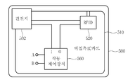
도 5와 도 6은 본 발명에 따른 비접촉 식별장치가 구비된 비접촉 IC 카드의 블럭구성도.5 and 6 are block diagrams of a contactless IC card having a contactless identification device according to the present invention;
도 7은 본 발명의 실시예에 따른 비접촉 식별장치의 외관 예시도.Figure 7 is an exemplary view of the appearance of a contactless identification device according to an embodiment of the present invention.
도 8은 본 발명의 실시예에 따른 비접촉 식별장치의 사용상태를 나타낸 도면.8 is a view showing a state of use of the contactless identification device according to an embodiment of the present invention.
도 9는 본 발명의 제1실시예에 따른 비접촉 식별장치의 작동제어장치의 상세 회로도.9 is a detailed circuit diagram of an operation control apparatus of a non-contact identification apparatus according to the first embodiment of the present invention.
도 10은 본 발명의 제2실시예에 따른 비접촉 식별장치의 작동제어장치의 상세 회로도.10 is a detailed circuit diagram of an operation control apparatus of a non-contact identification apparatus according to a second embodiment of the present invention.
도 11은 본 발명의 제3실시예에 따른 비접촉 식별장치의 작동제어장치의 상세 회로도.11 is a detailed circuit diagram of an operation control apparatus of a non-contact identification apparatus according to a third embodiment of the present invention.
도 12는 본 발명의 제4실시예에 따른 비접촉 식별장치의 작동제어장치의 상세 회로도.12 is a detailed circuit diagram of an operation control apparatus for a contactless identification device according to a fourth embodiment of the present invention.
도 13은 본 발명의 제5실시예에 따른 비접촉 식별장치의 작동제어장치의 상세 회로도.13 is a detailed circuit diagram of an operation control apparatus of a non-contact identification apparatus according to a fifth embodiment of the present invention.
본 발명은 비접촉 식별장치에 관한 것으로, 보다 상세하게는 비접촉 스마트카드나 RFID(Radio Frequency Identification)와 같은 비접촉식 식별장치에의 전원 인가 온/오프 기능 또는 회로 내에서 데이터의 흐름을 제어하는 제반 전자회로(이하, '통신경로'라 함)의 동작을 온/오프 할 수 있는 기술에 관한 것이다.The present invention relates to a contactless identification device, and more particularly, to a power supply on / off function for a contactless identification device such as a contactless smart card or a radio frequency identification (RFID) or an electronic circuit for controlling the flow of data within a circuit. (Hereinafter referred to as 'communication path') relates to a technology that can be turned on / off.
최근까지 ID 인식 분야에서 바코드 시스템과 마그네틱 카드시스템이 물류분야, 공중전화카드, 신용카드 등에 적용되어 실생활에 많이 이용되어 왔으나 기술의 발전, 생활양식의 변화 등으로 개선된 방식의 스마트카드, IC 카드, RFID 등의 활용이 늘어나고 있다. 특히, 유비쿼터스 사회의 구현에는 상기 비접촉식 식별장치가 주요한 부분을 차지할 것으로 예상된다.Until recently, barcode systems and magnetic card systems have been widely used in real life as they are applied to logistics, public phone cards, and credit cards in the field of ID recognition.However, smart cards and IC cards have been improved due to technological developments and lifestyle changes. , The use of RFID is increasing. In particular, the contactless identification device is expected to occupy a major part in the implementation of the ubiquitous society.
스마트카드 또는 IC 카드(플라스틱 카드, 보통 신용카드의 크기)에는 프로세서(Micro- processor), 운영체제, 보안회로, 기억장치 외에도 여러 가지 기능 등을 갖춘 집적회로 칩이 내장되어 있어, 특정 트랜잭션(transaction)을 프로세싱(processing)할 수 있는 능력 즉, 데이터 처리, 외부와의 통신 등을 할 수 있으므로 카드 리더에 그 카드의 데이터를 읽히게 되는 데, 그 방식에 따라 접촉식, 비접촉식 또는 혼용식 카드 등으로 구분한다.Smart cards or IC cards (plastic cards, usually the size of a credit card) contain an integrated circuit chip with a microprocessor, an operating system, a security circuit, a storage device, and many other functions. The ability to process data, such as data processing and external communication, allows the card reader to read the data from the card, depending on how it is used, such as a contact, contactless, or mixed-use card. Separate.
RFID는 무선주파수에서 전자기 또는 정전기 결합(coupling) 기술과 데이터 처리 기술을 통합적으로 이용하여 사물 등을 식별하는 기술이다. 이는 바코드 시스템을 대체할 수 있는 새로운 기술 패러다임으로서 산업, 물류 분야뿐만 아니라 유비쿼터스 시스템 등에서의 사용이 확산되고 있다. 이러한 RFID의 장점은 상당한 거리에서도 비접촉적인 방법으로 정보전달이 가능하다는 것이다.RFID is a technology for identifying objects and the like by using electromagnetic or electrostatic coupling (coupling) technology and data processing technology at a radio frequency. This is a new technology paradigm that can replace the bar code system, and its use in ubiquitous systems as well as in the industrial and logistics fields is spreading. The advantage of RFID is that information can be transmitted in a contactless way over a significant distance.
일반적으로 RFID 시스템은 카드 리더를 포함한 트랜시버 및 무선 안테나로 된 ‘판독부분’ 과 트랜스폰더라 하는 태그(tag)로 이루어진 ‘카드부분’ 등으로 구성된다. 신호 데이터를 실은 무선주파수를 이용하여 트랜시버는 트랜스폰더를 활성화시키고, 트랜스폰더는 무선주파수를 정류, 평활하여 활성화되면 저장된 데이터를 트랜시버로 안테나를 통해 전송한다.In general, an RFID system consists of a "reading part" consisting of a transceiver including a card reader and a wireless antenna, and a "card part" consisting of a tag called a transponder. The transceiver activates the transponder by using the radio frequency loaded with the signal data, and the transponder rectifies and smoothes the radio frequency to transmit the stored data to the transceiver through the antenna.
RFID 시스템 중 저주파(30KHz ~ 500KHz) 용은 약 1.8m 이하의 짧은 전송 영역에서 사용되며, 고주파(850MHz ~ 950MHz 또는 2.4GHz ~ 2.5GHz) 용은 27m 이상 먼거리까지 전송 능력을 갖을 수 있다. 여기서 IC 카드, 비접촉식 스마트 카드, RFID 등과 같은 시스템들을 통틀어 ‘비접촉식 식별장치’라 한다.Low frequency (30KHz ~ 500KHz) of RFID system is used in short transmission area of about 1.8m or less, and high frequency (850MHz ~ 950MHz or 2.4GHz ~ 2.5GHz) can have a transmission capability over a distance of 27m or more. In this context, systems such as IC cards, contactless smart cards, and RFID are referred to as "contactless identification devices."
도 1은 일반적인 비접촉식 IC 카드시스템의 구성을 그린 개략도로서, 이는 비접촉식 IC 카드 리더(10, 이하 ‘카드리더’라 한다.)와 비접촉식 IC 카드(20, 이하 ‘IC 카드’라 한다.)로 이루어진다.1 is a schematic diagram showing the configuration of a general contactless IC card system, which is composed of a contactless IC card reader 10 (hereinafter referred to as a "card reader") and a contactless IC card (hereinafter referred to as an "IC card"). .
도면을 참조하면, 카드리더(10)는 특정 주파수의 전자파를 연속적으로 방사하고, IC카드(20)는 카드리더(10)의 주파수에 동조되면 그 전자파를 전원으로 하여 활성화된다. 그 전원으로 활성화된 IC 카드(20)는 카드리더(10)로부터의 명령을 받은 후, 정상적인 명령이 수신되었다고 판단되면 그에 대한 응답을 카드리더(10)로 전송한다.Referring to the drawing, the
카드리더(10)는 명령어를 송출하고 나서 표준에서 규정하는 지연시간이 지난 후에도 IC카드(20)로부터 응답이 없으면 그 이상의 통신을 중단한다.The
상술되어진 도 1에 도시된 비접촉 식별 시스템은, 수동형의 경우에는 카드리더로부터 전송되는 RF신호에서 전력을 추출하여 이를 카드의 모든 회로에 공급하고, 능동형의 경우에는 별도의 전원(배터리나 충전지)을 장착하여 카드회로에 전력을 공급함으로써 카드리더와 카드 사이에 데이터를 교신한다.The above-described non-contact identification system shown in FIG. 1 extracts power from an RF signal transmitted from a card reader in the case of the passive type and supplies it to all circuits of the card, and supplies a separate power source (battery or rechargeable battery) in the active type. Data is exchanged between the card reader and the card by supplying power to the card circuit.
이와 같은 비접촉식 IC 카드의 동작에 대해서는 ISO/IEC10536과 ISO/IEC14443으로 권고되어 있는 바, CCIC(Contactless IC Card)는 전자로, RCCC(Remote Coupling Communication Card)는 후자로 구분되어 권고되어 있다.The operation of such a contactless IC card is recommended in ISO / IEC10536 and ISO / IEC14443. The CCIC (Contactless IC Card) is electronic and the RCCC (Remote Coupling Communication Card) is recommended.
그런데 비접촉식 식별장치를 이용한 IC 카드시스템을 주민등록증(이하 ‘주민증’이라 한다.)이나 기업 종업원들의 신분증 등으로 이용하는 경우, 국민이나 기업 종업원들의 행동이 시스템에 의해 감시될 수 있다는 기본적 인권 침해에 관한 문제가 제기되어 편리함을 알면서도 이용되는 데 큰 문제점이 있었다.However, when the IC card system using a contactless identification device is used as a resident registration card (hereinafter referred to as a 'resident card') or an ID card for corporate employees, the problem of basic human rights violations that the behavior of the people or employees can be monitored by the system. There was a big problem in being used while knowing convenience.
본 발명은 상기한 문제점을 해결하기 위한 것으로서, 비접속 식별장치가 구비된 주민증이나 신분증의 소지자가 비접촉 식별시스템의 카드리더의 통신 가능 영역에 진입하더라도 상기 소지자가 요청하는 경우에만 상기 비접촉 식별장치에 저장된 데이터가 상기 카드리더 측으로 전송될 수 있도록 하는 것을 목적으로 한다.The present invention is to solve the above problems, even if the holder of the resident or identification card equipped with a non-access identification device enters the communication region of the card reader of the contactless identification system only when the holder requests the contactless identification device It is an object to allow stored data to be transmitted to the card reader side.
또한, 본 발명은 상기 비접촉 식별장치 소지자의 요청시에만 상기 비접촉 식별장치에 저장된 데이터가 상기 비접속 식별장치의 카드리더로 전송되도록 함으로써, 인권 침해 문제에 대한 해결 방안을 갖는 것을 또 다른 목적으로 한다.In addition, another object of the present invention is to have a solution to the human rights violation problem by allowing data stored in the contactless identification device to be transmitted to the card reader of the contactless identification device only at the request of the contactless identification device holder. .
이를 위한 본 발명의 실시예에 따른 비접촉 식별장치는, 카드 리더와 무선으로 송수신하는 데이터를 처리하는 제반 동작 회로와; 상기 동작회로로 전원을 공급하는 전원부를 구비하는 비접촉 식별장치에 있어서, 상기 전원부로부터 출력되는 전원을 입력받아 상기 비접촉 식별장치 소지자의 요청시에만 상기 전원이 상기 제반 동작 회로로 인가되도록 상기 전원부와 상기 동작회로간의 전원경로를 스위칭 제어하는 작동제어장치를 더 구비하는 것을 특징으로 한다.A contactless identification device according to an embodiment of the present invention for this purpose, and a general operation circuit for processing data transmitted and received wirelessly with the card reader; A non-contact identification device having a power supply unit for supplying power to the operation circuit, wherein the power supply unit and the power supply unit receive power supplied from the power supply unit so that the power is applied to the general operation circuit only at the request of the non-contact identification device holder. And an operation control device for switching the power paths between the operation circuits.
또한, 본 발명의 실시예에 따른 비접촉 식별장치는, 카드 리더와 무선으로 송수신하는 데이터를 처리하는 제반 동작 회로(통신경로)와; 상기 동작회로로 전원을 공급하는 전원부를 구비하는 비접촉 식별장치에 있어서, 상기 전원부로부터 출력되는 전원을 입력받아 상기 비접촉 식별장치 소지자의 요청시에만 상기 통신경로가 동작되도록 스위칭 제어하는 작동제어장치를 더 구비하는 것을 특징으로 한다.In addition, the non-contact identification device according to an embodiment of the present invention, the general operation circuit (communication path) for processing data transmitted and received wirelessly with the card reader; In the non-contact identification device having a power supply for supplying power to the operation circuit, the operation control device for switching the control so that the communication path is operated only upon the request of the holder of the non-contact identification device receives the power output from the power supply. It is characterized by including.
바람직하게, 상기 작동제어장치는 기계적 스위치를 구비하는 것을 특징으로 한다.Preferably, the operation control device is characterized in that it comprises a mechanical switch.
바람직하게, 상기 작동제어장치는 전자적 스위치를 구비하는 것을 특징으로 한다.Preferably, the operation control device is characterized in that it comprises an electronic switch.
바람직하게, 상기 전자적 스위치는 소정 저항값이 형성되는 경우에만 상기 전원경로 또는 상기 통신경로를 도통시키는 것을 특징으로 한다.Preferably, the electronic switch is configured to conduct the power path or the communication path only when a predetermined resistance value is formed.
바람직하게, 상기 소정 저항값은 신체적 접촉에 의하여 형성되는 것을 특징으로 한다.Preferably, the predetermined resistance value is characterized by being formed by physical contact.
바람직하게, 상기 작동제어장치는 상기 저항값의 형성을 입력받기 위한 입력단자; 상기 입력단자를 통해 저항값이 형성되면, 상기 전원경로 또는 상기 통신경로를 도통시키는 스위칭소자를 구비하는 것을 특징으로 한다.Preferably, the operation control device comprises an input terminal for receiving the formation of the resistance value; When the resistance value is formed through the input terminal, it characterized in that it comprises a switching element for conducting the power path or the communication path.
바람직하게, 상기 입력단자는 상기 비접촉 식별장치의 표면에 노출되어 설치되는 것을 특징으로 한다.Preferably, the input terminal is characterized in that the exposure is installed on the surface of the non-contact identification device.
바람직하게, 상기 스위칭소자는 적어도 사리이스터, FET, 트랜지스터, 전자칩을 이용한 토클 스위칭방식, 및 사리이스터와 트랜지스터 또는 FET가 결합된 방식 중 하나를 구비하는 것을 특징으로 한다.Preferably, the switching device is characterized by having at least one of a thyristor, a FET, a transistor, a toggle switching method using an electronic chip, and a combination of the thyristor and a transistor or a FET.
바람직하게, 상기 전원부는 안테나를 통해 수신한 RF 신호로부터 전원을 생성하는 것을 특징으로 한다.Preferably, the power supply unit is characterized in that for generating power from the RF signal received through the antenna.
바람직하게, 상기 전원부는 적어도 배터리, 건전지, 및 충전지 중 하나인 것을 특징으로 한다.Preferably, the power supply unit is at least one of a battery, a battery, and a rechargeable battery.
이하, 본 발명의 바람직한 실시예를 첨부된 도면을 참조하여 상세히 설명한 다.Hereinafter, exemplary embodiments of the present invention will be described in detail with reference to the accompanying drawings.
도 2a는 일반적인 수동형 비접촉 식별장치(카드)를 도시한 개략도로서, 도면을 참조하면 동 식별장치는 안테나(210), 아날로그 신호 처리부(220), 디지털 신호 처리부(230), 논리연산부(240) 및 전원부(250)로 구성되어 있다.FIG. 2A is a schematic diagram illustrating a general passive contactless identification device (card). Referring to the drawings, the identification device includes an
도 2a에 도시된 각 부의 기능을 상세하게 설명한다.The function of each part shown in FIG. 2A is demonstrated in detail.
안테나(210)는 통신을 수행하는 외부장치(예를 들면, 카드 리더기)와 RF 신호로 데이터를 주고 받는 기능을 수행하는 모듈로서, 외부로부터 수신된 RF 신호를 안테나(210)의 두 단자(Ant+, Ant-)와 연결된 아날로그 신호 처리부(220)로 전송하는 기능을 수행한다.The
아날로그 신호 처리부(220)는 안테나(210)로부터 수신된 RF방식의 반송파 신호에서 기준 클럭을 재생하여 디지털 신호 처리부(230)로 전송함과 동시에 고주파 무선신호를 복조한 후 복조된 데이터를 디지털 신호 처리부(230)로 전송하는 기능을 수행한다. 또, 아날로그 신호 처리부(220)는 디지털 신호 처리부(230)로부터 수신받은 송신 데이터를 부하 변조하여 안테나(210)로 전송하여, 변조된 신호가 카드 리더측으로 송신되도록 한다.The
디지털 신호 처리부(230)는 아날로그 신호처리부(220)로부터 전송된 데이터를 논리연산부(240)로 전송하고, 논리연산부(240)로부터 수신받은 데이터를 일차 변조하여 아날로그 신호 처리부(220)로 전송하는 기능을 수행한다.The
논리연산부(240)는 마이크로프로세서(CPU)(도시 생략)와 메모리(도시 생략), 논리소자(도시 생략) 등으로 구성되어, 소정 프로토콜에 따라 카드 리더와 통신하 기 위한 전반적인 동작제어를 수행한다.The
도 2a에 도시된 아날로그 신호 처리부(220), 디지털 신호 처리부(230), 및 논리연산부(240)는 카드리더(10)와 무선으로 송수신하는 데이터를 처리하는 동작 회로에 해당한다.The
전원부(250)는 안테나(210)의 출력단자(Ant+, Ant-)를 통해 인가되는 RF 신호를 정류하고 평활하여 직류전원을 만들어 장치 전반에 제공하는 기능을 수행한다.The
도 2b는 본 발명의 실시예에 따른 비접촉 식별장치의 구성도로서, 동 도면에 도시된 구성요소 중 도 2a에 도시된 구성요소와 동일한 기능을 수행하는 구성요소에 대해서는 도 2a와 동일한 참조부호를 부여하고, 그에 대한 상세한 설명을 생략하기로 한다.FIG. 2B is a block diagram of a contactless identification device according to an embodiment of the present invention, and the same reference numerals as those of FIG. 2A are used for those elements that perform the same functions as those shown in FIG. 2A. And a detailed description thereof will be omitted.
본 발명에 따른 작동제어장치(260)는 전원부(250)에서 공급되는 전원을 I(Input) 단자로 입력받고, O(Output) 단자를 통해 장치전반에 동작 전원을 제공하는 기능을 수행한다. 특히, 본 발명의 작동제어장치(260)는 기계적 스위치 모듈 내지는 전자적 스위치 모듈이 구비되고, 전자적 스위치 모듈은 A 단자와 B 단자 사이에 소정 저항치(0~수십 KΩ)가 연결되는 경우에만 도통되어 I 단자로 입력된 전원이 O 단자로 출력될 수 있도록 한다. 즉, 본 발명이 작동제어장치(260)는 상기 A 단자와 B 단자간에 소정 저항치가 연결되는 경우에만 도통되어 O 단자로 전원이 출력됨으로써, 장치전반에 동작전원이 공급되어 상기 비접촉식 식별장치가 정상 동작할 수 있도록 한다.
상기 비접촉식 식별장치는 도 3에 개시된 바와 같이, 능동형 비접촉 식별장치(카드)에도 구현될 수 있다.The contactless identification device may also be implemented in an active contactless identification device (card), as shown in FIG.
도 3에 도시된 전원부(350)는 독립적으로 건전지 또는 배터리(또는 충전지)를 구비하여 장치 전반으로 전원을 공급하는데, 본 발명에 따른 작동제어장치(260)는 I 단자를 통해 전원부(350)로부터 출력되는 전원을 입력받고, O 단자를 통해 상기 장치전반으로 동작전원을 공급함으로써, 전원부(350)에서 동작회로(320~350)로 연결되는 전원경로에 대한 스위칭 제어를 수행한다.The
도 4는 이동통신단말기에 본 발명에 따른 작동제어장치(460)를 구비된 상태의 블럭구성도이고, 도 5는 건전지(502)를 사용하는 비접촉 IC 카드에 본 발명에 따른 작동제어장치(560)가 구비된 상태의 블럭구성도이고, 도 6은 충전지(602)를 사용하는 비접촉 IC 카드에 본 발명에 따른 작동제어장치(660)가 구비된 상태의 블럭구성도이다.4 is a block diagram of a state in which the
도 4, 도 5, 및 도 6에 각각 도시된 작동제어장치(460, 550, 660)는 도 2와 도 3을 통해 상술된 작동제어장치(260, 360)과 동일하게 동작한다.The
한편, 본 발명에서는 이동통신단말기, 비접촉 IC 카드에 작동제어장치가 구비되는 경우만을 설명하였지만, 상술한 예에 한정하지 않고 PDA 단말기, 휴대용 컴퓨터, 엠피쓰리 플레이어, 신용카드, 현금카드, 교통카드, 신분증, 주민등록증(주민증), 운전면허증, 의료보험증, 여권 등 비접촉 식별장치가 구비되는 모든 장치에 적용될 수 있다.On the other hand, the present invention has been described only when the operation control device is provided in a mobile communication terminal, a contactless IC card, not limited to the above-described examples PDA terminal, portable computer, MP3 player, credit card, cash card, transportation card, It can be applied to all devices equipped with contactless identification devices such as identification card, resident registration card (resident card), driver's license, medical insurance card and passport.
한편, 본 발명에 따른 작동제어장치(260, 360, 460, 560, 660)의 A 단자와 B 단자는 도 7에 도시된 바와 같이, 비접촉 IC 카드의 표면에 노출되도록 설치하고, 도 8과 같이 카드 소지자가 비접촉 IC 카드의 표면에 노출된 A 단자와 B 단자에 신체 일부를 접촉하면 상기 A 단자와 B 단자간에 소정 저항치가 형성되어 동작회로로 전원이 공급되도록 한다.On the other hand, the A terminal and the B terminal of the operation control device (260, 360, 460, 560, 660) according to the present invention is installed to be exposed to the surface of the non-contact IC card, as shown in FIG. When the card holder contacts a part of the body with the A terminal and the B terminal exposed on the surface of the contactless IC card, a predetermined resistance value is formed between the A terminal and the B terminal to supply power to the operation circuit.
도 8에 도시된 바와 같이, 상기 카드 소지자가 손가락을 상기 A 단자와 상기 B 단자에 접촉시켜 본 발명에 따른 작동제어장치를 동작시킬 수도 있지만, 손가락 이외의 신체적 접촉을 통해서도 소정 저항치 또는 유전율 변화 형성이 가능하므로 손가락을 제외한 신체적 접촉을 통해서도 본 발명에 따른 작동제어장치를 동작시킬 수 있다.As shown in FIG. 8, the card holder may operate the operation control apparatus according to the present invention by bringing a finger into contact with the A terminal and the B terminal, but also changes a predetermined resistance value or dielectric constant through physical contact other than a finger. Because of this, it is possible to operate the operation control device according to the present invention also through physical contact except the finger.
도 9는 본 발명에 따른 비접촉 식별장치의 작동제어장치가 사리이스터를 이용하여 구비되는 경우의 상세회로도이다.9 is a detailed circuit diagram when the operation control device of the non-contact identification device according to the present invention is provided using a thyristor.
도 9에 의하면, 상기 작동제어장치에서 상기 비접촉 식별장치 소유자의 신체적 접촉에 의해 상기 A 단자와 상기 B 단자 간에 소정 저항치가 형성되면, 상기 사리이스터(S)가 도통되어 I 단자로부터 인입된 전원이 O 단자로 출력된다.According to FIG. 9, when a predetermined resistance value is formed between the A terminal and the B terminal by physical contact of the owner of the non-contact identification device in the operation control apparatus, the thyristors S are turned on to supply power drawn from the I terminal. Output to O terminal.
도 10은 본 발명에 따른 비접촉 식별장치의 작동제어장치가 FET를 이용하여 구비되는 경우의 상세회로도이다.10 is a detailed circuit diagram when the operation control device of the non-contact identification device according to the present invention is provided using the FET.
도 10에 의하면, 상기 작동제어장치에서 상기 비접촉 식별장치 소유자의 신체적 접촉에 의해 상기 A 단자와 상기 B 단자 간에 소정 저항치가 형성되면, 제 1 FET(F1)와 제 2 FET(F2)가 도통됨에 따라 I 단자로부터 인입된 전원이 O 단자로 출력된다.According to FIG. 10, when a predetermined resistance value is formed between the A terminal and the B terminal by physical contact of the owner of the non-contact identification device in the operation control device, the first FET F1 and the second FET F2 become conductive. Accordingly, power input from the I terminal is output to the O terminal.
도 11은 본 발명에 따른 비접촉 식별장치의 작동제어장치가 트랜지스터를 이용하여 구비되는 경우의 상세회로도이다.11 is a detailed circuit diagram when the operation control device of the non-contact identification device according to the present invention is provided using a transistor.
도 11에 의하면, 상기 작동제어장치에서 상기 비접촉 식별장치 소유자의 신체적 접촉에 의해 상기 A 단자와 상기 B 단자 간에 소정 저항치가 형성되면, 제 1 트랜지스터(T1)과 제 2 트랜지스터(T2)가 도통됨에 따라 I 단자로부터 인입된 전원이 O 단자로 출력된다.According to FIG. 11, when a predetermined resistance value is formed between the A terminal and the B terminal by physical contact of the owner of the non-contact identification device in the operation control device, the first transistor T1 and the second transistor T2 are turned on. Accordingly, power input from the I terminal is output to the O terminal.
도 12는 본 발명에 따른 비접촉 식별장치의 작동제어장치가 전자칩(예컨대, IC 4049) 등을 이용한 토글(Toggle) 스위치 방식으로 구비되는 경우의 상세회로도이다. A 단자가 토글 스위치로 동작하며 전자칩은 A 단자에 신체적 접촉에 있는 것을 감지하여 트랜지스터를 온/오프시킨다.12 is a detailed circuit diagram when the operation control device of the non-contact identification device according to the present invention is provided with a toggle switch method using an electronic chip (eg, IC 4049) or the like. The A terminal acts as a toggle switch, and the electronic chip detects that it is in physical contact with the A terminal and turns the transistor on and off.
도 13은 본 발명에 따른 비접촉 식별장치의 작동제어장치가 사리이스터와 트랜지스터를 결합하여 구비되는 경우의 상세회로도이다.13 is a detailed circuit diagram when the operation control device of the non-contact identification device according to the present invention is provided by combining a thyristor and a transistor.
본 발명의 실시예에서는 비접촉 식별장치의 작동제어장치가 소정 저항치의 설정여부에 따라 온/오프가 결정되는 전자적 스위치를 개시하였지만, 상기 비접촉 식별장치의 소유자가 물리적 조작에 의해 온/오프할 수 있는 기계적 스위치를 상기 전자적 스위치를 대신하여 적용할 수도 있다.In the embodiment of the present invention, although the operation control device of the non-contact identification device discloses an electronic switch in which on / off is determined according to whether a predetermined resistance value is set, the owner of the non-contact identification device can turn on / off by physical operation. Mechanical switches may be applied in place of the electronic switches.
또한, 본 발명의 실시예에서는 제반 동작 회로로 인가되는 전원 경로를 스위칭제어하여 상기 비접촉 카드의 작동을 제어하는 방식을 설명하였지만, 상술한 실시예에 한정하지 않고 제반 동작 회로 내에 구성되는 통신경로의 양 단 사이에 상술되어진 작동제어장치가 구성되어 상기 통신경로의 도통상태를 스위칭 제어함으 로써 상기 비접촉 카드 소지자가 상기 비접촉 카드에 신체적 접촉을 한 경우에만 상기 비접촉 카드가 동작하도록 구성할 수도 있다.In addition, although the embodiment of the present invention has described a method of controlling the operation of the contactless card by switching and controlling a power path applied to the general operation circuit, the communication path configured in the general operation circuit is not limited to the above-described embodiment. The operation control device described above is configured between both ends to switch the conduction state of the communication path so that the contactless card can be operated only when the contactless card holder makes physical contact with the contactless card.
이상에서 설명한 바와 같이 본 발명의 실시예에 따른 비접촉 식별장치(예컨대, RFID 카드)의 작동제어장치에 의하면, 상기 비접촉 식별장치의 전원 공급회로 또는 제반 전자회로에 신체 접촉으로 동작할 수 있는 전자적 스위치를 부가함으로써 언제, 어디서나 발생할 수 있는 인권 침해 문제를 일거에 해소시켜 RFID 사용 한계를 무한대로 확장시킬 수 있는 효과가 있다. 이는 유비쿼터스 환경 U-City, 더나아가 U-Korea 실현에 초석이 될 것이다.As described above, according to the operation control apparatus of the non-contact identification device (for example, an RFID card) according to the embodiment of the present invention, an electronic switch that can operate in physical contact with the power supply circuit or the various electronic circuits of the non-contact identification device. By adding the, it is possible to solve the human rights violations that can occur anytime, anywhere at a time to expand the limits of RFID use indefinitely. This will be the cornerstone of realizing U-City U-City and U-Korea.
한편, 본 발명은 상술한 실시예로만 한정되는 것이 아니라 본 발명의 요지를 벗어나지 않는 범위내에서 수정 및 변형하여 실시할 수 있고, 이러한 수정 및 변경 등은 이하의 특허 청구의 범위에 속하는 것으로 보아야 할 것이다.On the other hand, the present invention is not limited to the above-described embodiment, but can be modified and modified within the scope not departing from the gist of the present invention, such modifications and changes should be regarded as belonging to the following claims. will be.
Claims (14)
Applications Claiming Priority (2)
| Application Number | Priority Date | Filing Date | Title |
|---|---|---|---|
| KR1020050116800 | 2005-12-02 | ||
| KR20050116800 | 2005-12-02 |
Publications (1)
| Publication Number | Publication Date |
|---|---|
| KR20070058366A true KR20070058366A (en) | 2007-06-08 |
Family
ID=38092468
Family Applications (2)
| Application Number | Title | Priority Date | Filing Date |
|---|---|---|---|
| KR1020060007006A KR20070058282A (en) | 2005-12-02 | 2006-01-23 | Apparatus for operating control of rfid |
| KR1020060121640A KR20070058366A (en) | 2005-12-02 | 2006-12-04 | Apparatus for operating control of rfid |
Family Applications Before (1)
| Application Number | Title | Priority Date | Filing Date |
|---|---|---|---|
| KR1020060007006A KR20070058282A (en) | 2005-12-02 | 2006-01-23 | Apparatus for operating control of rfid |
Country Status (2)
| Country | Link |
|---|---|
| KR (2) | KR20070058282A (en) |
| WO (1) | WO2007064178A1 (en) |
Families Citing this family (4)
| Publication number | Priority date | Publication date | Assignee | Title |
|---|---|---|---|---|
| US8253569B2 (en) | 2007-12-03 | 2012-08-28 | Yu Yung Choi | Secure electromagnetic data storage element having a plurality of selectively determined switchable security modes |
| WO2009152182A2 (en) * | 2008-06-09 | 2009-12-17 | Yu Yung Choi | Secure electromagnetic data storage element having a plurality of selectively determined switcheable security modes |
| CN104992721A (en) * | 2015-07-24 | 2015-10-21 | 张小亚 | MP3 player with card reader |
| CN109327216A (en) * | 2018-10-18 | 2019-02-12 | 广州众诺电子技术有限公司 | A kind of starting-up method and device based on electromagnetic induction |
Family Cites Families (2)
| Publication number | Priority date | Publication date | Assignee | Title |
|---|---|---|---|---|
| US6863220B2 (en) * | 2002-12-31 | 2005-03-08 | Massachusetts Institute Of Technology | Manually operated switch for enabling and disabling an RFID card |
| KR20050092331A (en) * | 2004-03-15 | 2005-09-21 | (주)지엔씨 | Usability and security enhancement for electronic credit card |
-
2006
- 2006-01-23 KR KR1020060007006A patent/KR20070058282A/en not_active Application Discontinuation
- 2006-12-04 KR KR1020060121640A patent/KR20070058366A/en not_active Application Discontinuation
- 2006-12-04 WO PCT/KR2006/005177 patent/WO2007064178A1/en active Application Filing
Also Published As
| Publication number | Publication date |
|---|---|
| WO2007064178A1 (en) | 2007-06-07 |
| KR20070058282A (en) | 2007-06-08 |
Similar Documents
| Publication | Publication Date | Title |
|---|---|---|
| KR100584328B1 (en) | Mobile Terminal Circuit Integrated With A Radio Frequency Identification Transponder And Radio Frequency Identification Method Thereof | |
| CN101313341B (en) | A means to deactivate a contactless device | |
| EP2250631B1 (en) | Methods and apparatus for preserving privacy in an rfid system | |
| EP2147400B1 (en) | Anti-interrogation for portable device | |
| JP3890958B2 (en) | Wireless communication apparatus and control method therefor, storage medium, and computer program | |
| US20100045446A1 (en) | Rfid system using human body communication | |
| KR101276878B1 (en) | apparatus and method for action control of RFID system | |
| CN101404066B (en) | Smart card cooperated with SIM card and its data processing method | |
| KR100988813B1 (en) | Multi-mode rfid reader architecture | |
| JP4692807B2 (en) | Contact-type data communication device, transmission / reception device, and transmission / reception method | |
| JP2005513679A (en) | Non-contact portable object including at least one peripheral device connected to the same antenna as the chip | |
| KR101003827B1 (en) | Card having a plural RFID chips and recognizing by using a non-contact method | |
| US10032105B2 (en) | IC card, portable terminal, and portable electronic apparatus | |
| KR20070058366A (en) | Apparatus for operating control of rfid | |
| KR101056726B1 (en) | RFID tag with current flow control switch | |
| JP2005222097A (en) | Mobile equipment | |
| KR20060119477A (en) | Smart card with security function | |
| KR100701124B1 (en) | RFID devices and system for integrated wireless terminal | |
| KR100747508B1 (en) | Rfid tag recognizable with both sides and system comprising the rfid tag | |
| KR200299286Y1 (en) | apparatus utilize to active type contactless IC card from passive type contactless IC card | |
| KR100434824B1 (en) | Apparatus for identification of dual-band radio frequency | |
| EP1688871B1 (en) | Wireless communication device interconnectivity | |
| KR200401805Y1 (en) | Battery for Mobile Phone Having RF R/W Module | |
| JP2001005921A (en) | Non-contact type data carrier system | |
| KR20150014715A (en) | Both Sides Radio Frequency Communication Tag |
Legal Events
| Date | Code | Title | Description |
|---|---|---|---|
| A201 | Request for examination | ||
| E902 | Notification of reason for refusal | ||
| E601 | Decision to refuse application |