KR20070056037A - Drive schemes for driving cholesteric liquid crystal material into the focal conic state - Google Patents
Drive schemes for driving cholesteric liquid crystal material into the focal conic state Download PDFInfo
- Publication number
- KR20070056037A KR20070056037A KR1020077000791A KR20077000791A KR20070056037A KR 20070056037 A KR20070056037 A KR 20070056037A KR 1020077000791 A KR1020077000791 A KR 1020077000791A KR 20077000791 A KR20077000791 A KR 20077000791A KR 20070056037 A KR20070056037 A KR 20070056037A
- Authority
- KR
- South Korea
- Prior art keywords
- liquid crystal
- pulse
- cholesteric liquid
- crystal material
- pulses
- Prior art date
Links
Images


Classifications
-
- G—PHYSICS
- G09—EDUCATION; CRYPTOGRAPHY; DISPLAY; ADVERTISING; SEALS
- G09G—ARRANGEMENTS OR CIRCUITS FOR CONTROL OF INDICATING DEVICES USING STATIC MEANS TO PRESENT VARIABLE INFORMATION
- G09G3/00—Control arrangements or circuits, of interest only in connection with visual indicators other than cathode-ray tubes
- G09G3/20—Control arrangements or circuits, of interest only in connection with visual indicators other than cathode-ray tubes for presentation of an assembly of a number of characters, e.g. a page, by composing the assembly by combination of individual elements arranged in a matrix no fixed position being assigned to or needed to be assigned to the individual characters or partial characters
- G09G3/34—Control arrangements or circuits, of interest only in connection with visual indicators other than cathode-ray tubes for presentation of an assembly of a number of characters, e.g. a page, by composing the assembly by combination of individual elements arranged in a matrix no fixed position being assigned to or needed to be assigned to the individual characters or partial characters by control of light from an independent source
- G09G3/36—Control arrangements or circuits, of interest only in connection with visual indicators other than cathode-ray tubes for presentation of an assembly of a number of characters, e.g. a page, by composing the assembly by combination of individual elements arranged in a matrix no fixed position being assigned to or needed to be assigned to the individual characters or partial characters by control of light from an independent source using liquid crystals
- G09G3/3611—Control of matrices with row and column drivers
- G09G3/3622—Control of matrices with row and column drivers using a passive matrix
- G09G3/3629—Control of matrices with row and column drivers using a passive matrix using liquid crystals having memory effects, e.g. ferroelectric liquid crystals
-
- G—PHYSICS
- G02—OPTICS
- G02F—OPTICAL DEVICES OR ARRANGEMENTS FOR THE CONTROL OF LIGHT BY MODIFICATION OF THE OPTICAL PROPERTIES OF THE MEDIA OF THE ELEMENTS INVOLVED THEREIN; NON-LINEAR OPTICS; FREQUENCY-CHANGING OF LIGHT; OPTICAL LOGIC ELEMENTS; OPTICAL ANALOGUE/DIGITAL CONVERTERS
- G02F1/00—Devices or arrangements for the control of the intensity, colour, phase, polarisation or direction of light arriving from an independent light source, e.g. switching, gating or modulating; Non-linear optics
- G02F1/01—Devices or arrangements for the control of the intensity, colour, phase, polarisation or direction of light arriving from an independent light source, e.g. switching, gating or modulating; Non-linear optics for the control of the intensity, phase, polarisation or colour
- G02F1/13—Devices or arrangements for the control of the intensity, colour, phase, polarisation or direction of light arriving from an independent light source, e.g. switching, gating or modulating; Non-linear optics for the control of the intensity, phase, polarisation or colour based on liquid crystals, e.g. single liquid crystal display cells
- G02F1/133—Constructional arrangements; Operation of liquid crystal cells; Circuit arrangements
- G02F1/1333—Constructional arrangements; Manufacturing methods
- G02F1/1335—Structural association of cells with optical devices, e.g. polarisers or reflectors
-
- G—PHYSICS
- G02—OPTICS
- G02F—OPTICAL DEVICES OR ARRANGEMENTS FOR THE CONTROL OF LIGHT BY MODIFICATION OF THE OPTICAL PROPERTIES OF THE MEDIA OF THE ELEMENTS INVOLVED THEREIN; NON-LINEAR OPTICS; FREQUENCY-CHANGING OF LIGHT; OPTICAL LOGIC ELEMENTS; OPTICAL ANALOGUE/DIGITAL CONVERTERS
- G02F1/00—Devices or arrangements for the control of the intensity, colour, phase, polarisation or direction of light arriving from an independent light source, e.g. switching, gating or modulating; Non-linear optics
- G02F1/01—Devices or arrangements for the control of the intensity, colour, phase, polarisation or direction of light arriving from an independent light source, e.g. switching, gating or modulating; Non-linear optics for the control of the intensity, phase, polarisation or colour
- G02F1/13—Devices or arrangements for the control of the intensity, colour, phase, polarisation or direction of light arriving from an independent light source, e.g. switching, gating or modulating; Non-linear optics for the control of the intensity, phase, polarisation or colour based on liquid crystals, e.g. single liquid crystal display cells
- G02F1/137—Devices or arrangements for the control of the intensity, colour, phase, polarisation or direction of light arriving from an independent light source, e.g. switching, gating or modulating; Non-linear optics for the control of the intensity, phase, polarisation or colour based on liquid crystals, e.g. single liquid crystal display cells characterised by the electro-optical or magneto-optical effect, e.g. field-induced phase transition, orientation effect, guest-host interaction or dynamic scattering
- G02F1/13718—Devices or arrangements for the control of the intensity, colour, phase, polarisation or direction of light arriving from an independent light source, e.g. switching, gating or modulating; Non-linear optics for the control of the intensity, phase, polarisation or colour based on liquid crystals, e.g. single liquid crystal display cells characterised by the electro-optical or magneto-optical effect, e.g. field-induced phase transition, orientation effect, guest-host interaction or dynamic scattering based on a change of the texture state of a cholesteric liquid crystal
-
- G—PHYSICS
- G09—EDUCATION; CRYPTOGRAPHY; DISPLAY; ADVERTISING; SEALS
- G09G—ARRANGEMENTS OR CIRCUITS FOR CONTROL OF INDICATING DEVICES USING STATIC MEANS TO PRESENT VARIABLE INFORMATION
- G09G2300/00—Aspects of the constitution of display devices
- G09G2300/04—Structural and physical details of display devices
- G09G2300/0469—Details of the physics of pixel operation
- G09G2300/0478—Details of the physics of pixel operation related to liquid crystal pixels
- G09G2300/0482—Use of memory effects in nematic liquid crystals
- G09G2300/0486—Cholesteric liquid crystals, including chiral-nematic liquid crystals, with transitions between focal conic, planar, and homeotropic states
-
- G—PHYSICS
- G09—EDUCATION; CRYPTOGRAPHY; DISPLAY; ADVERTISING; SEALS
- G09G—ARRANGEMENTS OR CIRCUITS FOR CONTROL OF INDICATING DEVICES USING STATIC MEANS TO PRESENT VARIABLE INFORMATION
- G09G2310/00—Command of the display device
- G09G2310/06—Details of flat display driving waveforms
- G09G2310/065—Waveforms comprising zero voltage phase or pause
Landscapes
- Physics & Mathematics (AREA)
- Nonlinear Science (AREA)
- Chemical & Material Sciences (AREA)
- Crystallography & Structural Chemistry (AREA)
- General Physics & Mathematics (AREA)
- Engineering & Computer Science (AREA)
- Optics & Photonics (AREA)
- Computer Hardware Design (AREA)
- Theoretical Computer Science (AREA)
- Mathematical Physics (AREA)
- Liquid Crystal (AREA)
- Devices For Indicating Variable Information By Combining Individual Elements (AREA)
Abstract
콜레스테릭 액정 표시 디바이스(24)에서, 콜레스테릭 액정 재료의 표면 안정화된 층을 포컬 코닉 상태로 구동하기 위해, 펄스 열(30, 34, 35, 36, 37, 38, 41)을 포함하는 구동 신호가 인가된다. 적어도 하나의 처음 펄스는 콜레스테릭 액정 재료층을 호메오트로픽 상태로 구동할 충분할 에너지를 갖고, 후속 펄스는 콜레스테릭 액정 재료층이 포컬 코닉 상태로 구동되는 최소 레벨로 감소하는 시간-평균된 에너지를 갖는다. 이것은 특히 낮은 반사율의 포컬 코닉 상태를 생성하고, 이는 높은 콘트라스트비가 달성될 수 있게 한다.In the cholesteric liquid crystal display device 24, pulse trains 30, 34, 35, 36, 37, 38, 41 are included to drive a surface stabilized layer of cholesteric liquid crystal material into a focal conic state. The drive signal is applied. At least one initial pulse has sufficient energy to drive the cholesteric liquid crystal material layer to the homeotropic state, and subsequent pulses are time-averaged to decrease to the minimum level at which the cholesteric liquid crystal material layer is driven to the focal conic state. Have energy. This creates a particularly low reflectance focal conic state, which allows high contrast ratios to be achieved.
콘트라스트 비, 콜레스테릭 액정, 펄스 열, 포컬 코닉 상태, 호메오트로픽 상태 Contrast ratio, cholesteric liquid crystal, pulse train, focal conic state, homeotropic state
Description
본 발명은 콜레스테릭 액정 재료의 포컬 코닉 상태로의 구동에 관한 것이다. 본 발명은 특히 포컬 코닉 상태가 어두운 상태로 이용되는 콜레스테릭 액정 표시 디바이스의 특정 애플리케이션을 구비하고 있다.The present invention relates to the drive of a cholesteric liquid crystal material into a focal conic state. The present invention has particular applications for cholesteric liquid crystal display devices in which the focal conic state is used in a dark state.
이하에서는 본 명세서의 마지막에 참조문헌의 리스트에 대한 전체 참조들이 제공되는 다수의 기술적 문헌들을 참조한다.Reference is now made to a number of technical documents at the end of this specification in which full references are provided to the list of references.
안정화된 콜레스테릭 텍스쳐(SCT) 표시 디바이스로 종종 알려져 있는 콜레스테릭 액정 표시 디바이스가 공지되어 있다. 이들 표시 디바이스들은 2가지 안정된 상태, 즉 콜레스테릭 액정 재료의 플래너 텍스쳐(플래너 상태)로부터 발생하는 컬러링된 반사 상태 및 반사 상태에 비해 거의 투명한 상태인, 포컬 코닉 텍스쳐(포컬 코닉 상태)로부터 발생하는 약간 광 후방 산란 상태를 가지는 재료 타입인 콜레스테릭 액정 재료를 이용한다. 상용으로 가용한 SCT 표시 디바이스에서, 포컬 코닉 상태는 어두운 상태로서 작용하고, 표시 디바이스는 블랙 배경층을 구비하여 투과된 광을 흡수한다.Cholesteric liquid crystal display devices, which are often known as stabilized cholesteric texture (SCT) display devices, are known. These display devices originate from two stable states: the colored reflective state resulting from the planar texture (planar state) of the cholesteric liquid crystal material and the focal conic texture (focal conic state), which is almost transparent to the reflected state. A cholesteric liquid crystal material is used which is a material type having a slightly light backscattering state. In commercially available SCT display devices, the focal conic state acts as a dark state, and the display device has a black background layer to absorb the transmitted light.
이들 안정된 상태들은 투명하고 임계 필드(Vc) 이상의 전계가 양의 유전체 이방성을 가져야 하는 액정에 인가되는 경우에만 존재하는 준안정된 호메오트로픽 상태를 통해 액세스될 수 있다. 이들 효과들은 처음에 Greubel에 의해 기술되었고, 나중에는 다른 사람들에 의해 예를 들면 미국특허 제5,463,863호에 기술되었다.These stable states can be accessed through metastable homeotropic states that exist only when transparent and an electric field above the critical field Vc is applied to the liquid crystal which must have positive dielectric anisotropy. These effects were first described by Greubel and later by others, for example in US Pat. No. 5,463,863.
콜레스테릭 액정 재료의 양태는 이하와 같이 이해될 수 있다. 콜레스테릭 액정 재료는 Vc 이상의 고전압을 인가하여 재료를 호메오트로픽 상태로 구동한 후 재료가 플래너 상태로 완화되도록 구동 신호를 제거함으로써 플래너 상태로 구동될 수 있다. 이어서, 주어진 전압의 구동 펄스가 인가된 후, 블랙 배경에 대한 재료의 반사율이 측정될 수 있다. 재료를 플래너 상태로 구동한 후 구동 펄스를 인가하는 이러한 프로세스는 다른 전압의 구동 펄스에 대해 반복되어 도 1에 도시된 바와 같은 형태를 가지고 있는 전압에 대한 반사율의 커브를 생성할 수 있다. 이러한 커브는 재료의 다양한 안정 상태들 간의 변이를 나타내는 임계점 V1 내지V4를 가지고 있다. 유의할 점은, V4는 상기 참조된 임계 전압 Vc와 동일하다는 점이다. V1 이하 및 V4 이상의 구동 펄스에 대해, 재료는 플래너 상태에 있고, V2와 V4간의 구동 펄스에 대해, 재료는 포컬 코닉 상태에 있다. 커브는 또한 표시 디바이스에서 그레이 레벨을 생성하는데 이용될 수 있는 상태인, V1과 V2의 사이 및 V3과 V4의 사이 간의 가변 반사율의 안정된 상태가 존재한다는 것을 보여주고 있다.The aspect of a cholesteric liquid crystal material can be understood as follows. The cholesteric liquid crystal material can be driven to the planar state by applying a high voltage of Vc or higher to drive the material to the homeotropic state and then removing the drive signal so that the material is relaxed to the planar state. Then, after a drive pulse of a given voltage is applied, the reflectance of the material against the black background can be measured. This process of driving the material into the planar state and then applying a drive pulse can be repeated for a drive pulse of another voltage to produce a curve of reflectivity for a voltage having a shape as shown in FIG. 1. These curves have thresholds V1 through V4 that represent the transitions between the various stable states of the material. Note that V4 is equal to the threshold voltage Vc referenced above. For drive pulses below V1 and above V4, the material is in the planar state, and for drive pulses between V2 and V4, the material is in the focal conic state. The curve also shows that there is a stable state of variable reflectivity between V1 and V2 and between V3 and V4, which states can be used to generate gray levels in the display device.
도 1의 커브는 콜레스테릭 액정 디스플레이에 대한 대부분의 구동 방식에 대한 기본을 형성한다. 예를 들면, 기본적인 구동 방식은 도 1의 커브를 생성하는데 이용되는 타입의 구동 펄스, 즉 재료를 호메오트로픽 상태로 구동하는 초기 펄스, 이에 이어서 완화 주기, 이어서 가변 반사율의 안정된 상태를 선택하는 가변 에너지의 선택 펄스를 이용하는 것이다.The curve of FIG. 1 forms the basis for most driving schemes for cholesteric liquid crystal displays. For example, the basic driving scheme is a drive pulse of the type used to generate the curve of FIG. 1, that is, an initial pulse that drives the material into a homeotropic state, followed by a relaxation period, followed by a variable to select a stable state of variable reflectance. It is to use a selection pulse of energy.
V1 내지 V4의 값들은 표시 디바이스의 정확한 특성 및 구성에 따라 가변되므로, 대부분의 구동 방식에 대해, 당해 표시 디바이스에 대해 V1 내지 V4의 값들이 결정되어야 한다. 이것은 V1 내지 V4가 예측 가능하도록 엄격한 스펙의 디바이스 제조 또는 제조 디바이스의 개별적인 테스트 및 셋업 중 어느 하나를 요구하므로, SCT 표시 디바이스의 제조에서 부담이 된다.Since the values of V1 to V4 vary depending on the exact characteristics and configuration of the display device, for most driving schemes, the values of V1 to V4 should be determined for the display device. This is a burden in the manufacture of SCT display devices since either V1 to V4 require either strict specification device fabrication or individual testing and setup of the fabrication device to be predictable.
SCT 표시 디바이스의 콘트라스트 비는 어두운 상태의 반사율에 대한 밝은 상태의 반사율의 비율로서 정의된다. 높은 콘트라스트를 달성하기 위해, 콜레스테릭 액정 재료는 밝은 상태에서 높은 반사율을 가져야 하지만, 콜레스테릭 액정 재료가 어두운 상태(액정 재료가 포컬 코닉 상태에 있는 경우에 사용으로 가용한 SCT 표시 디바이스에서 발생함)에서 낮은 반사율을 가지고 광의 후방 산란에 의해 저하되지 않아야 한다는 것도 동일하게 중요하다. 그러므로 높은 콘트라스트 비의 SCT 표시 디바이스를 생산하기 위해, 낮은 반사율의 어두운 상태를 제공하는 것이 필요하다.The contrast ratio of the SCT display device is defined as the ratio of reflectance in the bright state to reflectance in the dark state. In order to achieve high contrast, the cholesteric liquid crystal material must have high reflectance in the bright state, but occurs in the SCT display device available for use when the cholesteric liquid crystal material is in the dark state (when the liquid crystal material is in the focal conic state). Equally important is to have a low reflectivity and not be degraded by backscattering of light. Therefore, to produce a high contrast ratio SCT display device, it is necessary to provide a dark state of low reflectance.
또한, 다른 컬러(통상적으로는, 적색, 녹색 및 청색)의 광을 반사하는 콜레스테릭 액정층을 가지는 3가지 다른 셀의 스택들이 완전한 컬러 표시 디바이스를 생성하는데 이용되는 경우, 하위 셀에 의해 생성된 컬러는 상위 셀에서 산란되는 광에 의해 변형된다. 매우 자주, 액정 재료층들의 배향은 밝은 플래너 상태를 여전히 제공하면서도 낮은 광 산란 포컬 코닉 상태를 시도하고 달성하도록 최적화된 다. 배향은 또한 어떠한 전압도 인가되지 않은 상태에서 상태들이 안정될 수 있게 한다. 배향층 내에서 모든 이들 최적화를 구하는 것이 항상 가능한 것은 아니다.In addition, when stacks of three different cells having cholesteric liquid crystal layers reflecting light of different colors (typically red, green and blue) are used to produce a full color display device, they are generated by sub-cells. The color is transformed by the light scattered in the upper cell. Very often, the orientation of the liquid crystal material layers is optimized to try and achieve low light scattering focal conic states while still providing a bright planar state. The orientation also allows the states to be stable without any voltage applied. It is not always possible to find all these optimizations in the alignment layer.
긴 피치 길이 콜레스테릭 디바이스(IR 광을 반사함)에 대한 Gerber에 의한 제1 문헌은, 전계(처음에는 임계 전압 Vc 이상임)가 빠르게 스위치 오프되는 경우, 플래너 텍스쳐가 형성된다는 것을 가르쳐 주고 있다. Gerber는 또한, 전계가 느리게 스위치 오프되는 경우, 지문 텍스쳐가 형성된다는 것을 가르쳐 주고 있으며, 이것은 더 짧은 피치 콜레스테릭 액정 혼합물에서 나타나는 포컬 코닉 텍스쳐에 관련된 것으로 간주될 수 있다.Gerber's first document on long pitch length cholesteric devices (reflecting IR light) teaches that planner textures are formed when the electric field (which is initially above the threshold voltage Vc) is quickly switched off. Gerber also teaches that when the electric field is switched off slowly, a fingerprint texture is formed, which can be considered to be related to the focal conic texture appearing in the shorter pitch cholesteric liquid crystal mixture.
상기 설명된 기본적인 구동 방식뿐만 아니라, 상기 문헌에서 기술된 2개의 추가적인 구동 방식이 이제 검토될 것이다.In addition to the basic driving scheme described above, two additional driving schemes described in the above document will now be considered.
제1 추가 구동 방식은 Doane에 의해 기술된 것으로, 고전압 펄스를 인가하여 재료를 호메오트로픽 상태로 구동한 후, 제로 볼트로 고속 스위치 오프하여 플래너 텍스쳐를 제공하거나 더 낮은 전압으로 고속 스위치 오프하여 포컬 코닉 텍스쳐를 제공한다. 이들 중 후자는 고전압과 저전압 사이에서 중지를 가질 수 있다. 추가로, 저전압 펄스가 수 번 반복되어 포컬 코닉 텍스쳐의 광 산란을 감소시킬 수 있다. 이것은 느린 어드레싱 방식이다.The first additional driving scheme described by Doane is to apply a high voltage pulse to drive the material in a homeotropic state, then fast switch off to zero volts to provide a planar texture or to fast switch off to a lower voltage. Provides a conic texture. The latter of these may have a break between high and low voltages. In addition, the low voltage pulse may be repeated several times to reduce light scattering of the focal conic texture. This is a slow addressing scheme.
제2 추가 구동 방식은 다이내믹 구동 방식으로 지칭되고, Huang et al., Zhu and Huang 및 Huang and Stefanov에 의해 제안되었다. 이러한 방식은 5가지 구성요소, 준비, 포스트 준비, 선택, 포스트 선택 및 에볼루션으로 구성된다. 이것은 액정 디렉터(director)를 일부 위치로부터 매우 용이하게 스위칭할 수 있다는 사실 을 이용하고, 이러한 제1 이동은 준비 시간 동안에 달성된다. 그러나 이전 방식보다 훨씬 빠르지만, 더 적은 산란의 포컬 코닉 구동 방식을 생성하려고 시도하지 않는다.The second additional drive scheme is referred to as dynamic drive scheme and has been proposed by Huang et al., Zhu and Huang and Huang and Stefanov. This approach consists of five components: preparation, post preparation, selection, post selection, and evolution. This takes advantage of the fact that the liquid crystal director can be switched very easily from some position, and this first movement is achieved during the preparation time. However, it is much faster than the previous one, but does not attempt to create a less scattered focal conic drive scheme.
따라서, 본 기술분야에 2가지 오랫동안의 요구가 있다고 명백하게 말할 수 있다. 제1 요구는 콜레스테릭 액정 표시 디바이스에서 개선된 콘트라스트와 관련된다. 제2 요구는 LCD 제조 스펙의 완화, 즉 단순히 언급하면 제조자의 비용 절감과 연관되는 것과 관련된다. 이들 요구들 중 어느 하나를 충족하는 것이 바람직할 것이다.Thus, it can be clearly stated that there are two long demands in the art. The first need relates to improved contrast in cholesteric liquid crystal display devices. The second need relates to the easing of LCD manufacturing specifications, i.e. simply stated, associated with cost savings of manufacturers. It would be desirable to meet either of these needs.
본 발명의 제1 양태에 따르면, 구동 신호를 콜레스테릭 액정 재료층에 인가하는 단계를 포함하는 콜레스테릭 액정 재료층을 포컬 코닉 상태로 구동하는 방법이 제공되고, 구동 신호는 적어도 하나의 처음 펄스가 콜레스테릭 액정 재료층을 호메오트로픽 상태로 구동할 충분한 에너지를 가지고 있고, 후속 펄스는 콜레스테릭 액정 재료층이 포컬 코닉 상태로 구동되는 최소 레벨로 감소하는 시간-평균된 에너지를 가지는 펄스 열을 포함한다.According to a first aspect of the present invention, there is provided a method of driving a cholesteric liquid crystal material layer in a focal conic state comprising applying a drive signal to a cholesteric liquid crystal material layer, wherein the drive signal is at least one first. The pulse has sufficient energy to drive the cholesteric liquid crystal material layer to the homeotropic state, and the subsequent pulse has a time-averaged energy that decreases to the minimum level at which the cholesteric liquid crystal material layer is driven to the focal conic state. It includes a pulse train.
유사하게, 본 발명의 제2 양태에 따르면, 콜레스테릭 액정 재료층 및 구동 신호를 콜레스테릭 액정 재료층에 인가할 수 있는 전극 배열을 포함하는 적어도 하나의 셀, 및 액정 재료를 포컬 코닉 상태로 구동하도록 콜레스테릭 액정 재료층으로의 인가를 위해 구동 신호를 전극 배열에 공급하도록 배열된 구동 회로를 포함하는 콜레스테릭 액정 표시 디바이스를 제공하고, 여기에서 구동 신호는 적어도 하나의 처음 펄스가 콜레스테릭 액정 재료층을 호메오트로픽 상태로 구동할 충분한 에너지를 가지고 있고, 후속 펄스가 콜레스테릭 액정 재료층이 포컬 코닉 상태로 구동되는 최소 레벨로 감소하는 시간-평균된 에너지를 가지는 펄스 열을 포함한다.Similarly, according to a second aspect of the present invention, there is provided a cholesteric liquid crystal material layer and at least one cell comprising an electrode array capable of applying a drive signal to the cholesteric liquid crystal material layer, and the liquid crystal material in a focal conic state. A cholesteric liquid crystal display device comprising a drive circuit arranged to supply a drive signal to an electrode array for application to a layer of cholesteric liquid crystal material to drive a substrate, wherein the drive signal includes at least one first pulse. Pulse train with time-averaged energy that has enough energy to drive the cholesteric liquid crystal material layer to the homeotropic state, and the subsequent pulse decreases to the minimum level at which the cholesteric liquid crystal material layer is driven to the focal conic state. It includes.
그러므로 본 발명은 펄스 열을 포함하는 구동 신호를 이용하여 포컬 코닉 상태로 구동할 수 있게 한다. 하나 이상의 초기 펄스는 콜레스테릭 액정 재료를 호메오트로픽 상태로 구동한다. 후속 펄스는 시간-평균된 에너지를 줄이고 있다. 그러한 펄스 열은 액정 재료를 포컬 코닉 상태로 구동하는 것으로 발견되었다. 훨씬 더 중요한 것은, 그러한 구동 펄스 열에 의해 생성된 포컬 코닉 상태가 낮은 반사율, 특히 상기 설명된 주지의 구동 방식에 의해 생성된 것보다 더 낮은 반사율을 가지고 있는 것으로 발견되었다. 그러므로 본 발명은 표시 디바이스에 의해 더 높은 콘트라스트 비가 달성될 수 있게 한다. 유사하게, 콜레스테릭 액정 재료층의 스택을 가지고 있는 표시 디바이스의 경우에, 포컬 코닉 상태에서의 감소된 후방 산란은 표시 디바이스의 전체 컬러 범위(gamut)를 개선시킨다.Therefore, the present invention makes it possible to drive in a focal conic state by using a drive signal including a pulse train. One or more initial pulses drive the cholesteric liquid crystal material into a homeotropic state. Subsequent pulses are reducing time-averaged energy. Such pulse trains have been found to drive liquid crystal materials into focal conic states. Even more importantly, it has been found that the focal conic states generated by such drive pulse trains have lower reflectances, in particular lower reflectances than those produced by the known drive scheme described above. Therefore, the present invention allows a higher contrast ratio to be achieved by the display device. Similarly, in the case of a display device having a stack of cholesteric liquid crystal material layers, reduced backscattering in the focal conic state improves the overall gamut of the display device.
또 다른 장점은, 구동 방식은 상기 설명된 주지된 구동 방식보다 표시 디바이스의 정확한 특성 및 구성에 대한 훨씬 더 적은 종속성으로 포컬 코닉 상태가 신뢰성있게 달성될 수 있도록 한다는 점이다. 특히, 도 1의 V1 내지 V4 전압을 상세하게 알 필요가 없다. 여전히 더 필요한 것은, 적어도 하나의 초기 펄스가 콜레스테릭 액정 재료를 호메오트로픽 상태로 구동하기에 충분한 에너지를 가지는 것으로서, 이것은 비교적 높은 전압을 가지는 펄스를 제공함으로써, 예를 들면 그 펄스에 대해 고전압을 선택함으로써 간단하게 넓은 범위의 디스플레이를 용이하게 달성할 수 있다. 유사하게, 후속 펄스의 시간-평균된 에너지가 감소되는 최소 레벨은 콜레스테릭 액정 재료를 포컬 코닉 상태로 구동하도록 충분히 낮아야만 하는 것이 필요하지만, 다시 이것은 용이하게 달성된다. 디자인 제한을 최소화하기 위해, 시간-평균된 에너지는 제로의 최소값으로 감소될 수 있다. 포컬 코닉 상태로의 더 급속한 구동은 더 높은 최소 레벨을 선택함으로써 달성될 수 있고, 가변되는 펄스 열로 표시 디바이스를 테스트함으로써 최소 레벨의 실제값을 선택하는 것이 수월하다.Another advantage is that the drive scheme allows the focal conic state to be reliably achieved with much less dependence on the exact characteristics and configuration of the display device than the above-described well-known drive scheme. In particular, it is not necessary to know the voltages V1 to V4 in FIG. 1 in detail. Still more needed, the at least one initial pulse has enough energy to drive the cholesteric liquid crystal material into the homeotropic state, which provides a pulse with a relatively high voltage, for example a high voltage for that pulse. By simply selecting, a wide range of displays can be easily achieved. Similarly, the minimum level at which the time-averaged energy of the subsequent pulse is reduced needs to be low enough to drive the cholesteric liquid crystal material into the focal conic state, but again this is easily accomplished. To minimize design constraints, the time-averaged energy can be reduced to a minimum value of zero. Faster driving to the focal conic state can be achieved by selecting a higher minimum level, and it is easier to select the actual value of the minimum level by testing the display device with varying pulse trains.
표시 디바이스의 정확한 특성 및 구성에 대한 이러한 감소된 종속성은 개별적인 표시 디바이스의 제조 허용한도 및/또는 테스트를 줄임으로써 제조시 상당한 장점을 제공한다. 예를 들면, 액정 재료층의 두께는 덜 핵심적이다. 이것은 제조 비용을 감소시키고 수율을 증가시키므로 매우 중요하다.This reduced dependency on the exact nature and configuration of the display device provides significant advantages in manufacturing by reducing the manufacturing tolerances and / or testing of individual display devices. For example, the thickness of the liquid crystal material layer is less critical. This is very important as it reduces manufacturing costs and increases yield.
관련된 장점은, 표시 디바이스가 구부러지는 경우에 예측되지 않은 방식으로 극소적으로 가변되는 두께로 인해 구동시 문제를 발생시킬 수도 있는 유연한 표시 디바이스 상에서 구동 방식이 이용될 수 있다는 점이다.A related advantage is that the driving scheme can be used on a flexible display device, which may cause problems in driving due to the extremely variable thickness in an unexpected manner when the display device is bent.
콜레스테릭 액정 재료의 분자에 의해 겪는 물리적 현상은 완전하게 이해되지는 않지만, 그럼에도 불구하고 이하의 코멘트가 유용할 수 있다. 최종 상태는 포컬 코닉 상태이고, 감소된 산란에 대한 이유는 인가된 신호로부터 기인하는 도메인의 크기가 가시광의 파장에 비해 더 크거나 더 작은 평균에서 만들어지므로 가시광의 산란양이 감소된다는 것으로 이해될 수 있다. 이것이 펄스 열에 의해 달성되는 물리적 메커니즘은 분명하지 않다. 그러나 물리적 현상에 관한 이러한 불확실성은 상기 설명된 구동 펄스 열이 콜레스테릭 액정 재료를 낮은 반사율의 포컬 코닉 상태로 구동하는데 이용될 수 있는 실제 관찰에 기초하는 본 발명의 구현에 영향을 미치지 않는다.The physical phenomena experienced by the molecules of the cholesteric liquid crystal material are not fully understood, but the following comments may nevertheless be useful. The final state is the focal conic state, and the reason for the reduced scattering can be understood that the amount of scattering of visible light is reduced since the size of the domain resulting from the applied signal is made at an average larger or smaller than the wavelength of visible light. have. The physical mechanism by which this is achieved by the pulse train is not clear. However, this uncertainty regarding physical phenomena does not affect the implementation of the present invention based on the actual observation that the drive pulse train described above can be used to drive the cholesteric liquid crystal material into a low reflectivity focal conic state.
유의할 점은, 본 발명은 임의의 표면 처리에 적용될 수 있을 뿐만 아니라 임의의 콜레스테릭 액정 재료 및 임의의 배향 타입에도 적용가능하다는 점이다.Note that the present invention is not only applicable to any surface treatment but also to any cholesteric liquid crystal material and any type of orientation.
본 발명의 추가 양태에 따르면, (A) 뷰어로부터 가장 먼 곳에 소정 광학 표면 코팅(예를 들면, 블랙 흡수층)을 구비하는 전압 어드레싱가능한 콜레스테릭 재료의 적어도 하나의 환경적으로 인캡슐레이팅된 층, 및 (B) 소정 전압 시퀀스를 콜레스테릭 재료 내의 실질적으로 각각 어드레싱가능한 로케이션에 인가하기 위한 전자 구동 수단을 포함하는 표면-안정화된 콜레스테릭 텍스쳐 액정 표시 디바이스가 제공되고, 여기에서 구동 수단은 시간 도메인 근사 복수의 실질적으로 집합적으로 중립인 전기 펄스를 이용하여 호메오트로픽 필드 온 상태로부터 낮은 광 산란 포컬 코닉 텍스쳐 상태로 각 전압-대-콜레스테릭-재료 소자의 직접 스위칭을 특징으로 하며, 복수 내에, (i) 소자를 리셋하는 V4 전압-에너지-상태보다 큰 펄스가 있고, (ii) 그리고나서 적어도 실질적으로 V2 또는 실질적으로 V3 전압-에너지-상태가 그 내부에 포함될 때까지 각 전압-에너지-상태에서 빗나가는 클러스터링된 펄스 서브세트가 있으며, (iii) 임의의 주지된 구동 방식을 이용하여 낮은 광 산란 포컬 코닉 텍스쳐 상태로부터 호메오트로픽 필드 온 상태로의 소자의 직접 스위칭이 있다.According to a further aspect of the invention, (A) at least one environmentally encapsulated layer of voltage addressable cholesteric material having a predetermined optical surface coating (eg, a black absorbing layer) farthest from the viewer And (B) electronically driven means for applying a predetermined voltage sequence to a substantially respective addressable location in the cholesteric material, wherein the drive means Time Domain Approximation Direct switching of each voltage-to-cholesteric-material device from a homeotropic field on state to a low light scattering focal conic texture state using a plurality of substantially collectively neutral electric pulses. , Within a plurality, (i) there is a pulse greater than the V4 voltage-energy-state that resets the device, and (ii) then at least There is a clustered subset of pulses that deviate from each voltage-energy-state until qualitatively V2 or substantially V3 voltage-energy-states are contained therein, and (iii) low light scattering using any known drive scheme. There is a direct switching of the device from the focal conic texture state to the homeotropic field on state.
본 발명의 또 다른 양태에 따르면, 전기적 어드레싱을 통해 실질적으로 인캡슐레이팅된 콜레스테릭 소자에서 광학 상태-대-상태 변이를 구동하기 위한 방법이 제공되고, 상기 방법은 (1) 시간 도메인 근사 복수의 실질적으로 집합적으로 중립인 전기 펄스를 이용하여 호메오트로픽 필드 온 상태로부터 낮은 광 산란 포컬 코닉 텍스쳐 상태로 소자의 직접 스위칭의 단계 - 복수 내에, (1a) 소자를 리셋하는 V4 전압-에너지-상태보다 큰 펄스가 있고, (1b) 그리고나서 적어도 실질적으로 V2 또는 실질적으로 V3 전압-에너지-상태가 그 내부에 포함될 때까지 각 전압-에너지-상태에서 빗나가는 클러스터링된 펄스 서브세트가 있음 -, 및 임의의 주지된 구동 방식을 이용하여 낮은 광 산란 포컬 코닉 텍스쳐 상태로부터 호메오트로픽 필드 온 상태로의 소자의 직접 스위칭의 단계를 포함한다.According to another aspect of the present invention, there is provided a method for driving optical state-to-state variation in a substantially encapsulated cholesteric element via electrical addressing, the method comprising: (1) a time domain approximation plural; Direct switching of the device from a homeotropic field-on state to a low light scattering focal conic texture state using substantially collectively neutral electric pulses of-within a plurality, (1a) V4 voltage-energy- to reset the device. There is a pulse greater than the state, (1b) and then there is a clustered pulse subset that deviates from each voltage-energy-state until at least substantially V2 or substantially V3 voltage-energy-state is included therein, and Direct swap of the device from a low light scattering focal conic texture state to a homeotropic field on state using any known drive scheme. And a justification step.
본 발명의 추가 양태에 따르면, 그 내부에 실질적으로 인캡슐레이팅된 콜레스테릭 재료에 대한 셀 투명도를 달성하는 구동 방법이 제공되고, 여기에서 "V4 전압 x 지속기간"이상 영역 및 "V2-또는-V3 전압 x 지속기간" 아래로 내려가는 영역을 포함하는 복수의 영역을 구비하는 구동 "전압 x 지속기간" 인벨로프가 있다. ("전압 x 지속기간"이란, 펄스의 면적(다른 형태의 펄스에 대해서는 적분이나 계산하는데 적절한 근사화를 요구하지만, 정사각형 펄스에 대해 폭=지속기간에 의해 승산된 높이=전압임)이거나 펄스의 전체 에너지(면적에 등가인 방식으로 계산될 수 있음)를 의미한다).According to a further aspect of the present invention, there is provided a driving method for achieving cell transparency for a substantially encapsulated cholesteric material therein, wherein the region "V4 voltage x duration" or more and "V2-or There is a driving " voltage x duration " envelope having a plurality of regions including an area going down below -V3 voltage x duration. ("Voltage x Duration" means the area of the pulse (requires appropriate approximation for integration or calculation for other types of pulses, but for width pulses = height multiplied by duration = duration multiplied by duration) or the entirety of the pulse Energy (which can be calculated in a manner equivalent to area).
본 발명의 추가 양태에 따르면, (1) 적어도 하나의 셀 들 중 하나의 셀에, "V4 전압 x 지속기간" 이상의 에너지를 가지는 복수에서 적어도 하나의 초기 펄스를 인가하고, (2) "V2-또는-V3 전압 x 지속기간" 이하의 에너지를 가지는 복수들 중에서 적어도 하나의 최종 펄스를 셀에 인가하는 것을 포함하여 - (3) 여기에서 적어도 하나의 초기 펄스와 적어도 하나의 최종 펄스 사이에서 복수들 중의 임의의 펄스의 셀로의 임의의 인가는 "V4 전압 x 지속기간"과 "V2-또는-V3 전압 x 지속기간" 사이의 에너지를 가지고 있음 - 소정 시퀀싱된 복수의 에너지 펄스를 인가함으로써, 적어도 하나의 실질적으로 인캡슐레이팅된 셀에서 콜레스테릭 재료를 호메오트로픽 필드-온 상태로부터 낮은 광 산란 포컬 코닉 텍스쳐 상태로 구동하기 위한 방법이 제공된다.According to a further aspect of the invention, (1) at least one initial pulse is applied to one of the at least one cells with a energy of at least "V4 voltage x duration", and (2) "V2- Or-applying at least one final pulse to the cell among a plurality having energy less than " V3 voltage x duration "-(3) wherein the plurality between the at least one initial pulse and the at least one final pulse Any application of any of the pulses to the cell has an energy between "V4 voltage x duration" and "V2-or-V3 voltage x duration"-by applying a plurality of sequenced energy pulses, thereby at least one A method is provided for driving a cholesteric material from a homeotropic field-on state to a low light scattering focal conic texture state in a substantially encapsulated cell of.
더 나은 이해를 허용하기 위해, 본 발명의 실시예들은 이제 첨부된 도면을 참조하여 비제한적 예를 통해 설명될 것이다.To allow a better understanding, embodiments of the present invention will now be described by way of non-limiting example with reference to the accompanying drawings.
도 1은 초기에 플래너 상태인 콜레스테릭 액정 재료에 인가된 구동 펄스에 대한 반사율 대 전압의 그래프이다.1 is a graph of reflectance versus voltage for a drive pulse applied to a cholesteric liquid crystal material initially in a planar state.
도 2는 콜레스테릭 액정 표시 디바이스의 셀의 단면도이다.2 is a cross-sectional view of a cell of the cholesteric liquid crystal display device.
도 3은 콜렉스테릭 액정 표시 디바이스의 단면도이다.3 is a cross-sectional view of a Cholesteric liquid crystal display device.
도 4는 도 2의 셀의 전극 배열의 투시도이다.4 is a perspective view of the electrode arrangement of the cell of FIG. 2.
도 5는 셀의 콜레스테릭 액정 재료에 인가된 구동 신호의 오실로스코프 자취이다.5 is an oscilloscope trace of a drive signal applied to the cholesteric liquid crystal material of the cell.
도 6은 주지된 구동 신호를 도시한 도이다.6 shows a known drive signal.
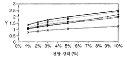
도 7은 도 5의 구동 신호에서 연속 펄스의 전압 강하에 대한 후방 산란된 광의 정도의 그래프이다.7 is a graph of the degree of backscattered light versus voltage drop of a continuous pulse in the drive signal of FIG. 5.
도 8은 도 5의 구동 신호가 강하된 펄스의 개수에 대한 강하된 펄스로 인가 되는 셀의 반사율의 그래프이다.FIG. 8 is a graph of reflectance of a cell to which the driving signal of FIG. 5 is applied as a dropped pulse to the number of dropped pulses.
도 9 내지 16은 일부 다른 구동 신호에 대한 전압 대 시간의 그래프이다.9-16 are graphs of voltage versus time for some other drive signals.
우선, 구동 방식이 적용되는 콜레스테릭 액정 표시 디바이스(24)가 설명될 것이다. 표시 디바이스(24)의 셀(10)은 도 2에 도시되어 있고, 층(layered) 구성을 가지고 있으며, 개별적인 층(11 내지 19)의 두께는 명료함을 위해 도 2에서 과장되어 있다.First, the cholesteric liquid
셀(10)은 유리 또는 양호하게는 플라스틱으로 만들어지는 2개의 단단한 기판(11, 12)을 포함한다. 기판(11, 12)은 그 내부 대향 표면상에, 투명한 도전성 재료, 통상 인듐 주석 산화물의 층으로 형성된 각 투명 도전층(13, 14)을 구비하고 있다. 도전층(13, 14)은 이하에 더 상세하게 설명되는 바와 같이, 패터닝되어 직접 어드레싱가능한 픽셀의 직사각형 어레이를 제공한다.The
선택적으로는, 각 도전층(13, 14)은 예를 들면, 실리콘 다이옥사이드의 각 절연층(15, 16), 또는 가능하다면 복수의 절연층으로 오버코팅된다.Optionally, each
기판(11, 12)은 이들 사이에 통상 3㎛ 내지 8㎛의 두께를 가지는 캐비티(20)를 정의한다. 캐비티(20)는 액정층(19)을 포함하고 캐비티(20)의 주변 주위에 제공된 접착 실(21)에 의해 밀봉된다. 그러므로 액정층(19)은 도전층(13, 14)의 사이에 배열된다.The
각 기판(11, 12)은 액정층(19)에 인접하여 형성된 각 배향층(17, 18)을 더 구비하고, 각 도전층(13, 14) 또는 제공되는 경우 절연층(15, 16)을 덮는다. 배향 층(17, 18)은 액정층(19)을 배향시켜 안정화시키고, 통상 선택적으로 하나의 방향으로 러빙된 폴리미이드로 만들어진다. 그러므로 액정층(19)은 다르게는 체적-안정화될 수도 있지만, 표면-안정화된다.Each
액정층(19)은 콜레스테릭 액정 재료를 포함한다. 그러한 재료는 반사율 및 투과율이 가변되는 수개의 상태를 가지고 있다. 이들 상태들은 여기에 참조로 첨부되고 그 사상이 본 발명에 적용된 I. Sage, "Liquid Crystals Applications and Uses", Editor B Bahadur, vol3, page 301, 1992, World Scientific에 기재된 바와 같이, 플래너 상태, 포컬 코닉 상태 및 호메오트로픽(의사 네마틱) 상태들이다.The
플래너 상태에서, 액정층(19)은 그것에 입사하는 광의 대역폭을 선택적으로 반사한다. 반사광의 파장 λ는 Bragg's 법칙에 의해, 즉 λ=nP에 의해 주어지고, 여기에서 λ는 반사된 광의 파장이며, n은 광에 의해 보여지는 액정 재료의 굴절률이고, P는 액정 재료의 피치 길이이다. 그러므로 원리적으로는, 피치 길이 P의 선택에 의해 디자인 선택으로서 임의의 컬러가 반사될 수 있다. 본 기술분야의 숙련자에게 주지된 바와 같이, 정확한 컬러를 결정하는 다수의 추가 인자들이 있다고 말할 수 있다. 모든 입사광이 플래너 상태로 반사되는 것은 아니다. 3개의 셀(10)을 채용하는 전형적인 전체 컬러 표시 디바이스(24)에서, 이하에 더 상세하게 설명되는 바와 같이, 전체 반사율은 통상 30% 정도의 수준이다. 액정층(19)에 의해 반사되지 않은 광은 액정층(19)을 투과하고, 이어서 나중에 더 상세하게 설명되는 블랙층(27)에 의해 흡수된다. 현재의 구동 방식에서, 플래너 상태는 밝은 상태로서 이용된다.In the planar state, the
포컬 코닉 상태에서, 액정층(19)은 플래너 상태에 비해, 투과형이고, 엄격하게 말하면 액정층(19)이 작은 반사율로, 통상 3-4%의 정도 수준으로 부드럽게 광을 산란하고 있지만, 입사광을 투과시킨다. 그러므로 셀(10) 뒤에 블랙층(27)이 있는 상태에서, 이하에 더 상세하게 설명된 바와 같이, 이러한 상태는 블랙으로서 감지된다. 현재의 구동 방식에서, 포컬 코닉 상태는 어두운 상태로 이용된다.In the focal conic state, the
포컬 코닉 및 플래너 상태는 액정층(19)에 어떠한 구동 신호도 인가되지 않은 경우에 동시에 존재할 수 있는 안정된 상태들이다. 또한, 액정층(19)은 액정 재료의 다른 도메인이 각각 포컬 코닉 상태 및 플래너 상태 중 각각의 하나에 존재하는 안정된 상태에 존재할 수 있다. 그러한 안정된 상태의 범위는 포컬 코닉 및 플래너 상태의 각각에서 액정의 양의 다른 혼합으로 가능하므로, 액정 재료의 전체 반사율은 안정된 상태에 걸쳐 가변된다.The focal conic and planar states are stable states that may exist simultaneously when no drive signal is applied to the
호메오트로픽 상태에서, 액정층(19)은 포컬 코닉 상태보다 훨씬 더 큰 투과성을 가지며, 통상 0.5-0.75% 정도의 반사율을 가지고 있다.In the homeotropic state, the
포컬 코닉 및 플래너 상태는 액정층(19)에 어떠한 구동 신호도 인가되지 않은 경우에 동시에 존재할 수 있는 안정된 상태들이다. 호메오트로픽 상태는 안정되지 않고, 액정층(19)을 호메오트로픽 상태로 구동하는 구동 신호의 중단시, 구동 신호가 제로 전압으로 고속 변이되는 경우, 액정층(19)은 짧은 주기에 걸쳐 안정된 상태, 예를 들면 플래너 상태로 완화된다.The focal conic and planar states are stable states that may exist simultaneously when no drive signal is applied to the
표시 디바이스(24)는 이제 도 3을 참조하여 설명될 것이다.The
표시 디바이스(24)는 각각이 도 2에 도시되고 상기 설명된 타입의 셀(10)인 셀(10R, 10G, 및 10B)의 스택을 포함한다. 셀(10R, 10G, 10B)은 각각 적색, 녹색 및 청색의 컬러로 광을 반사하도록 배열된 각 액정층(19)을 구비하고 있다. 그러므로 셀(10R, 10G, 및 10B)은 적색 셀(10R), 녹색 셀(10G) 및 청색 셀(10B)로 지칭될 것이다. 적색 셀(10R), 녹색 셀(10G) 및 청색 셀(10B)의 선택적 이용은 이미지의 전체 컬러 표시를 허용하지만, 일반적으로 표시 디바이스는 하나를 포함하여 임의의 개수의 셀(10)로 만들어질 수 있다.
도 3에서, 뷰어가 위치된 측으로부터 표시 디바이스(24)의 전방이 가장 높고 표시 디바이스(24)의 후방이 가장 낮다. 그러므로 전방에서 후방으로의 셀(10)의 순서는 청색 셀(10B), 녹색 셀(10G), 및 적색 셀(10R)이다. 원리상으로는 임의의 다른 순서가 이용될 수 있지만, 이러한 순서는 West and Bodnar, "Optimization of Stacks of Reflective Cholesteric Films for Full Colour Displays", Asia Display 1999 pp20-32에 개시된 이유로 인해 바람직하다.In FIG. 3, the front of the
셀(10R, 10G)의 인접 쌍 및 셀(10G, 10B)의 인접 쌍은 각각 각 접착층(25, 26)에 의해 함께 홀딩된다.Adjacent pairs of
표시 디바이스(24)는 특히 가장 뒤에 있는 적색 셀(10R)의 후방 표면에 형성됨으로써, 후방에 배치된 블랙층(27)을 구비하고 있다. 블랙층(21)은 블랙 페인트의 층으로서 형성될 수 있다. 이용시, 블랙층(27)은 셀(10R, 10G 또는 10B)에 의해 반사되지 않은 임의의 입사광을 흡수한다. 그러므로 모든 셀(10R, 10G, 또는 10B)이 블랙 상태로 스위칭되는 경우에, 표시 디바이스는 블랙으로 나타난다.The
표시 디바이스(24)는 여기에 참고로 첨부되고 그 사상이 본 발명에 적용된 WO 01/88688에 공개된 디바이스 타입과 유사하다.The
도전층(13, 14)은 콜레스테릭 액정 재료층(19)의 일부의 투시도인 도 4에 도시된 바와 같은 전극 배열을 제공하도록 패터닝되고, 도전층(13, 14)은 셀(10)의 다른 컴포넌트들이 명료함을 위해 생략된다. 특히, 각 도전층(13, 14)은 서로에게 수직으로 연장되는 각 도전층(13, 14)의 전극(28, 29)을 구비하는 선형 전극(28, 29)의 각 어레이로서 형성된다. 이것은 종래 패시브 멀티플렉싱된 어드레싱 전극 배열이다. 그러한 전극 배열은 2차원 직사각형 픽셀 어레이로서 각 도전층(13, 14)의 전극(28, 29) 간의 각 교차부에서 콜레스테릭 액정 재료층(19)의 일부를 어드레싱할 수 있다.The
다르게는, 도전층(13, 14)은 콜레스테릭 액정 재료층(19)의 일부의 픽셀로의 구동을 허용하는 일부 다른 전극 배열을 제공하도록 패터닝될 수 있다.Alternatively, the
제어 회로(22)는 구동 신호를 각 셀(10)의 도전층(13, 14)에 공급하여, 액정층(19)에 걸쳐 전계를 인가함으로써 각 픽셀의 액정 재료를 선택적으로 원하는 반사율을 가지는 안정된 상태로 구동한다. 제어 회로(22)는 종래 방식으로, 예를 들면 하나의 어레이의 전극(28)의 선택에 의해 연속적인 라인이 스캐닝되는 스캐닝 방식으로, 각 어레이의 개별적인 전극(28, 29)의 선택에 의해 각 픽셀을 어드레싱하고, 각 스캐닝된 라인에 대해, 다른 어레이의 각 전극(29)으로의 구동 신호의 공급에 의해 적절한 구동 신호가 각 픽셀에 인가된다.The
액정층(19)을 포컬 코닉 상태 이상의 반사율을 가지는 안정된 상태로 구동하기 위해, 제어 회로(22)는 주지된 형태의 구동 신호를 예를 들면 상기 설명된 주지 의 구동 방식에 따라 인가한다. 하나의 가능성은 구동 신호가 재료를 호메오트로픽 상태로 구동하는 초기 펄스, 이어서 완화 주기, 이어서 가변 반사율의 안정된 상태를 선택하는 가변 에너지의 선택 펄스로 구성된다. 선택 펄스는 도 1에 도시된 커브에 따라 선택된 전압을 가지므로 그 커브를 따른 임의의 포인트에서 반사율을 제공함으로써, 예를 들면 여기에 참고로 첨부되어 있고 그 사상이 본 발명에 적용된 Huang et al., "Full Colour(4096 Colours)Reflective Cholesteric Liquid Crystal Display", Asia Display 1998, pp 883-885, 1973에 개시된 바와 같이, 그레이 스케일이 달성될 수 있게 한다.In order to drive the
통상, 구동 신호는 펄스의 형태를 취한다. 펄스는 AC 또는 지속기간 50-100ms의 쌍극 펄스를 가지는 30-50V를 가져, 고속 스위치-오프인 호메오트로픽 상태로부터 플래너 상태로 액정을 스위칭한다. 구동 신호는 액정을 안정된 상태로 스위칭하는 10-20V 및 1-50ms 지속기간의 하나 이상(종종 2 내지 5)의 펄스일 수 있다. 다르게는, 짧은 지속기간을 가지는 30-50V의 펄스가 이용될 수 있다. 구동 펄스의 최적화는 정확한 진폭 및 지속기간이 액정층(19)의 두께, 액정의 유전체 이방성 및 온도와 같은 다수의 인자에 좌우되므로, 주어진 셀(10) 구성에 대해 실험적으로 발견될 수 있다. 그러므로 이들 값들이 최적화 프로세스를 위한 적합한 시작 값들이지만, 실제 구동 신호는 상기 주어진 값들과는 다를 수 있다.Typically, the drive signal takes the form of a pulse. The pulse has 30-50V with a bipolar pulse of AC or duration of 50-100 ms to switch the liquid crystal from the homeotropic state, which is a fast switch-off, to the planar state. The drive signal may be one or more (often 2-5) pulses of 10-20V and 1-50ms durations that switch the liquid crystal to a stable state. Alternatively, pulses of 30-50V with short duration can be used. The optimization of the drive pulse can be found experimentally for a given
액정층(19)을 포컬 코닉 상태로 구동하기 위해, 제어 회로(22)는 이제 설명될 본 발명에 따라 구동 신호를 인가한다. 주지된 구동 방식과 구별하는 것을 돕기 위해, 이러한 구동 신호는 LSS 구동 방식(LSS는 낮은 산란 방식을 표시함)이라 지칭될 것이다.In order to drive the
이하의 설명에서, 이하의 전압을 참조한다. V1 내지 V4는 도 1을 참조하여 상기 설명된 바와 같이 플래너 상태인 콜레스테릭 액정 재료에 대해 정의되고, 즉 V1은 재료의 상태를 변경시키지 않는 구동 펄스의 최대 전압이고, V2는 이를 완전한 포컬 코닉 상태로 스위칭하는 최소 전압이며, V3은 이를 완전한 포컬 코닉 상태로 스위칭하는 최대 전압이고, V4는 이를 완전한 호메오트로픽 상태로 스위칭하는 최소 전압이다. 또한, 로우 및 칼럼에서 서로에 수직으로 연장하는 선형 전극 어레이를 구비하는 표시 디바이스에 대해, Vr은 로우에 인가되는 전압이고, VcActive는 액티브(구동된) 칼럼에 인가된 전압이다.In the following description, reference is made to the following voltages. V1 to V4 are defined for the cholesteric liquid crystal material in planar state as described above with reference to FIG. 1, ie V1 is the maximum voltage of the drive pulse that does not change the state of the material, and V2 is a full focal conic The minimum voltage to switch to the state, V3 is the maximum voltage to switch it to the full focal conic state, and V4 is the minimum voltage to switch it to the full homeotropic state. Also, for a display device having a linear array of electrodes extending perpendicular to each other in rows and columns, Vr is the voltage applied to the row and VcActive is the voltage applied to the active (driven) column.
실질적으로는, 실시예들은 콜레스트릭으로부터 호메오트로픽 네마틱 변이와 관련되고, 이는 필드 효과이므로 마이크론 셀 두께당 전압으로 인용될 수 있다.In practice, the embodiments relate to homeotropic nematic variations from the crest, which can be referred to as voltage per micron cell thickness as it is a field effect.
셀(10)에 인가된 LSS 구동 신호의 예는 실제 구동 신호의 오실로스코프로부터의 전압 자취인 도 5에 도시되어 있다. 구동 신호는 교대 극성을 가지는 펄스 열(30)을 포함한다. 펄스(30)는 50ms의 지속기간을 가지고 있고 그 사이의 간격은 없다. 펄스(30)는 오실로스코프의 해상도로 인해 도 5에서 약간 라운딩되게 보이지만, 실제로는 정사각형 파형을 가지고 있다.An example of an LSS drive signal applied to
초기 펄스(30)는 액정층을 호메오트로픽 상태로 구동하는데 필요한 레벨(Vc) 이상의 진폭을 가지고 있다. 통상, 초기 펄스(30)는 50V 내지 60V 정도의 진폭을 가지고 있다. 후속 펄스(30)는 펄스(30)의 에너지가 단조롭게 감소되도록 단조롭게 감소하는 진폭을 가지고 있다. 펄스의 진폭 및 에너지는 제로로 감소된다. 이 러한 예에서, 반대 극성의 인접하는 펄스 쌍(30)은 동일한 극성을 가지고 있고, 동일한 극성의 각 연속 펄스(30)의 진폭은 5%만큼 감소한다. 이러한 펄스 열은 상기 설명된 주지된 구동 방식을 이용하여 액세스된 포컬 코닉 상태와 비교할 때, 층(19)의 액정 재료를 낮은 광 산란 정도를 가지고 따라서 낮은 반사율을 가지는 포컬 코닉 상태로 구동하는 것으로 발견되었다.The
LSS 구동 방식은 콜레스테릭 액정 재료를 호메오트로픽 상태로 구동하는 초기 리셋 펄스 이후에 고전압 전계가 갑자기 제거되고 완화 주기에 걸쳐 콜레스테릭 액정 재료가 플래너 상태로 완화된다는 점에서, 주지된 구동 방식과 비교될 수 있다. 유의할 점은, 이것은 액정 재료층(19)을 포컬 코닉 상태보다 더 높은 반사율을 가지는 안정된 상태로 구동하는 제어 회로(22)에 의해 이용되는 구동 방식이라는 점이다. 이러한 주지된 구동 방식에 대한 구동 신호는 초기 리셋 펄스(31, 일반적으로 하나의 극성을 가지는 펄스, DC 밸런스 펄스 또는 AC 펄스), 이어서 완화 주기(32), 및 이어서 선택 펄스(33)를 포함하는 도 6에 도시되어 있다. 복수일 수 있는 다수인 n개의 선택 펄스(33)가 있다. 액정 재료층(19)을 포컬 코닉 상태보다 더 높은 반사율을 가지는 안정된 상태로 구동함으로써 그레이 레벨을 달성하기 위해, 제어 회로(22)는 V1과 V2 또는 V3과 V4간의 전압을 가지는 선택 펄스(33)를 제공한다. 주지된 구동 방식에 따르면, 액정 재료층(19)을 포컬 코닉 상태로 구동하기 위해, 선택 펄스는 V2와 V3 사이의 전압을 가진다.The LSS driving scheme is well known in that the high voltage field is abruptly removed after the initial reset pulse driving the cholesteric liquid crystal material to the homeotropic state and the cholesteric liquid crystal material is relaxed to the planar state over the relaxation period. Can be compared with Note that this is a driving scheme used by the
제어 회로(22)가 주지된 구동 신호 대신에 LSS 구동 신호를 인가하여 포컬 코닉 상태를 달성하지만, 주지된 구동 신호 및 LSS 구동 신호 양쪽을 실제 셀(10) 에 인가하고 얻어진 콘트라스트 비를 측정함으로써 테스트가 수행되었다.The
우선, Nissan Chemicals로부터의 녹색 콜레스테릭 액정 폴리이미드인 각각의 SE130B 및 SE7511L인 액정층 재료층을 포함하는 2개의 셀(10)에 대해 테스트가 수행되었다. 각 경우에, 층(19)의 두께는 6㎛이었다. 주지된 구동 방식에 대한 이들 테스크 결과는 표 1에 도시되어 있고, LSS 구동 신호에 대한 결과는 표 2에 도시되어 있다.First, a test was performed on two
각 액정 재료에 대해, 플래너 상태는 동일한 반사율을 가지지만, 포컬 코닉 상태는 심지어 최상의 종래 방식이 LSS 구동 방식보다 훨씬 더 낮은 콘트라스트 비를 가지고 있도록 다른 반사율을 가진다.For each liquid crystal material, the planar state has the same reflectance, but the focal conic state has a different reflectance such that even the best conventional method has a much lower contrast ratio than the LSS drive method.
두 번째로, Merck S811 카이럴 도펀트를 포함하는 Merck BL087 호스트 액정인 액정 재료의 두께 6㎛의 층(19)을 포함하는 셀(10)에 대해 테스트가 수행되었다.Secondly, a test was performed on a
이 경우에, 주지된 구동 신호는 진폭 60V의 밸런싱된 DC 리셋 펄스(31), 50ms의 완화 주기(32), 및 지속기간 14ms 및 간격 50ms의 2개의 밸런싱된 DC 선택 펄스(33)로 인가되었다. 이것은 선택 펄스의 진폭이 27V인 경우에 최소 반사율 포컬 코닉 상태를 생성한다. 이 상태에서, 반사율은 표준 화이트의 2.65%이었고, 6.99의 콘트라스트 비를 제공하였다.In this case, the known drive signal was applied with a balanced
도 5에 도시된 형태의 LSS 구동 신호는 초기 펄스가 60V이고 동일한 극성의 각 연속 펄스(30)에 대해 전압 감소가 1V이며 각 양의 또는 음의 극성 펄스(30)가 5ms인 지속기간(즉, 2개의 펄스(30)로 구성된 밸런싱된 DC 펄스의 지속기간은 10ms이다)을 가지는 전압으로 인가되었다. 이것은 표준 화이트의 1.05%의 반사율을 가지는 포컬 코닉 상태를 제공했고, 17.61의 콘트라스트 비를 제공한다.The LSS drive signal of the type shown in FIG. 5 has a duration (i.e., an initial pulse of 60 V, a voltage drop of 1 V for each
다시, 이들 테스트들은 LSS 구동 신호가 개선된 반사율 및 콘트라스트 비를 가지는 포컬 코닉 상태의 생성을 허용하는 것을 보여주고 있다.Again, these tests show that the LSS drive signal allows the generation of focal conic states with improved reflectance and contrast ratios.
뿐만 아니라, 도 5에 도시된 펄스 열은 액정 재료의 전압 V1 내지 V4의 상세한 지식없이 구현될 수 있다는 것을 유의하는 것이 중요하다. 초기 펄스(30)는 V4 이상의 전압을 가져야 하지만, 당해 셀(10)에 대한 V4의 실제값이 결정될 필요가 없도록 비교적 높은 전압을 고르는 것이 용이하다. 펄스(30)의 전압의 감소는 동일하게 전압 V2 및 V3을 알 필요가 없다는 것을 의미한다. 이것은 전압 V2 및 V3이 액정 재료를 포컬 코닉 상태로 구동하기 위해서는 알려져야 하고, 이는 엄격한 허용한도가 셀(10)의 제조에 적용될 필요가 있거나 각 제조된 셀(10)의 테스트가 필요하기 때문에, 제조 난이도 및 비용을 증가시키는 주지된 구동 방식과 현저하게 비교되는 점이다. 그러므로 LSS 구동 신호의 펄스(30) 열의 이용은 이들 제조 문제를 감소시켜 감소된 비용 및 더 높은 수율을 허용한다.In addition, it is important to note that the pulse train shown in FIG. 5 can be implemented without detailed knowledge of the voltages V1 to V4 of the liquid crystal material. The
하나 이상의 초기 펄스 이후에, 감소하는 시간-평균화된 에너지를 가지는 후속 펄스가 있다면, 도 5에 도시된 LSS 구동 신호의 형태의 다수의 변동이 적용될 수 있다. 그러한 변형의 일부 예들은 이하와 같다.After one or more initial pulses, if there is a subsequent pulse with decreasing time-averaged energy, a number of variations in the form of the LSS drive signal shown in FIG. 5 may be applied. Some examples of such modifications are as follows.
펄스(30) 열의 전체 지속기간을 감소시키기 위해 다수의 변동이 적용될 수 있다. 전체 지속기간을 감소시키기 위한 3가지 가능성은 다음과 같다.Multiple variations can be applied to reduce the overall duration of the
(1) 각 연속 펄스(30)에 대한 전압 강하를 증가시킨다.(1) Increase the voltage drop for each
(2) 각 펄스(30)의 지속기간을 감소시킨다.(2) Reduce the duration of each
(3) 열에서 펄스(30)의 에너지가 떨어지는, 즉 제로로 떨어지는 대신에 제로 이상의 최소 레벨로 떨어지는 최소 레벨을 증가시킨다.(3) Increase the minimum level at which the energy of the
이들 3가지 가능성은 이하와 같이 연구되었다.These three possibilities were studied as follows.
(1) 각 연속 펄스(30)에 대한 전압 강하를 증가시킴.(1) Increase the voltage drop for each
연속적인 펄스(30)에 대한 전압 강하는 가변될 수 있다. 펄스(30) 당 전압의 1% 내지 10% 강하가 테스트되었다. 더 많은 펄스(30)에 대해, 즉 펄스(30)당 더 적은 전압 강하에 대해, 콘트라스트 비는 특히 호메오트로픽 배향과 함께 이용되는 경우에 조금 더 높은 것으로 발견되었다. 표 3은 지속기간 50ms 및 10ms 펄스의 펄스(30)가 상기 설명된 테스트에 이용된 동일한 타입, 특히 액정 재료의 동질 배향을 가지는 셀(10)에 이용되는 경우의 결과를 도시하고 있다.The voltage drop for
유사하게, 도 7은 플래너 상태에서 다른 반사 파장을 가지는 다른 액정 재료에 대한 데이터를 도시하고 있고, 도 7은 연속적인 펄스(30)의 전압 강하에 대한 후방 산란된 광(임의의 유닛으로 Y로 도시됨)의 정도의 그래프이다. 각 재료에 대해, 전압 강하가 감소함에 따라 후방 산란된 광의 감소가 있다.Similarly, FIG. 7 shows data for different liquid crystal materials having different reflection wavelengths in the planar state, and FIG. 7 shows backscattered light (with any unit Y as the voltage drop of successive pulses 30). Graph of degrees). For each material, there is a decrease in backscattered light as the voltage drop decreases.
(2) 각 펄스(30)의 지속기간의 감소.(2) Reduction of duration of each
일반적으로 펄스(30)의 지속기간은 100ms 이하이다. 도 5에 도시된 LSS 구동 신호의 펄스(30)의 지속기간은 동질 배향층(PI3, 19) 및 녹색 콜레스테릭 액정 재료를 구비하는 셀(10)을 이용하여 50ms로부터 10ms, 5ms 및 2.5ms의 값으로 감소되었다. 달성된 콘트라스트 비는 표 4에 도시되어 있다.In general, the duration of
표 4로부터, 더 긴 펄스(30)는 최상의 콘트라스트 비를 제공하지만, 펄스(30)의 지속기간에 일부 감소를 적용할 수 있고 따라서 콘트라스트 비에서 비교적 작은 비용으로 펄스(30)열의 전체 지속기간의 감소를 적용할 수 있다는 것을 알 수 있다. 밸런스 시, 펄스는 최대 20ms의 지속기간을 가지는 것이 바람직하다.From Table 4, although
표 4로부터 알 수 있는 바와 같이, 콘트라스트비가 상당히 저하되고, 이러한 특정 셀에 대해 5ms와 2.5ms의 사이 어딘가에 존재하는 임계값이 있지만, 일반적으로 이것은 아마도 재료 및 온도 종속성을 가진다. LSS 구동 방식이 여전히 작은 지속기간으로도 적용되지만, 이러한 이유 때문에, 펄스(30)는 적어도 5ms의 지속기간을 가지는 것이 바람직하다. 일반적으로, 펄스(30)의 지속기간은 다른 지속기간의 테스팅에 의해 이용되는 조건 및 재료에 대해 최적화될 수 있다.As can be seen from Table 4, the contrast ratio is considerably lowered and there is a threshold somewhere between 5 ms and 2.5 ms for this particular cell, but in general this probably has material and temperature dependencies. Although the LSS drive scheme still applies with a small duration, for this reason, the
(3) 열에서 펄스(30)의 에너지의 최소 레벨을 증가시킴.(3) increasing the minimum level of energy of
일반적으로, 액정 재료가 포컬 코닉 상태로 구동될 만큼 충분히 낮다면, 펄스(30)의 에너지가 떨어지는 최소 레벨은 제로 이상일 수 있다. 이는 셀(10)의 본성에 일부 제한을 두기는 하지만, 이러한 최소 레벨은 실험적으로 결정될 수 있는데 반해, 제로의 최소 레벨로의 감소는 임의의 셀에 적용가능하다. 그러므로 실제로는, 최소 레벨이 펄스(30)열의 전체 지속기간의 감소와 제조 제한을 증가시키는 것과의 밸런스로서 선택된다. 일반적인 용어로, 최소 레벨을 증가시키는 것은 제로인 최소 레벨과 비교하여, 50% 정도의 펄스(30)열의 전체 지속기간의 감소를 달성할 수 있다.In general, if the liquid crystal material is low enough to be driven into the focal conic state, the minimum level at which the energy of the
이를 증명하기 위해, 도 5에 도시된 구동 신호를 셀(10)에 인가하지만, 최소 레벨이 대응하여 증가되도록 열의 끝에서 증가하는 개수의 펄스(30)를 강하시킴으로써 일련의 테스트가 수행되었다. 그 결과는 강하된 펄스(30)의 개수에 대한 구동 신호의 인가 이후에 셀(10)의 반사율(임의의 단위)의 그래프인 도 8에 도시되어 있다. 2개의 다른 액정 재료에 대한 커브가 도시되어 있고, 삼각형은 적색 콜레스테릭 액정 재료에 대한 포인트를 나타내며, 정사각형은 녹색 콜레스테릭 재료에 대한 포인트를 나타낸다. 각 재료에 대해, 다수의 강하된 펄스들이 있고, 따라서 낮은 반사율 포컬 코닉 상태가 달성되기 중지하는 최소 에너지가 있다. 강하된 펄스의 개수, 따라서 최소 에너지는 녹색 콜레스테릭 액정 재료보다 적색 콜레스테릭 액정 재료에 대해 더 낮다. To prove this, a series of tests were performed by applying the drive signal shown in FIG. 5 to the
또한, 도 1에 도시된 커브가 초기 펄스(30)와 후속 펄스(30) 간에 중지없는 이러한 개념과 일치하는 방식을 이용하여 얻어지는 경우에, 최소 레벨은 대략 V2에 대응하고, 이것은 표 5에 도시된 바와 같이 실험적으로 결정되었다.Also, in the case where the curve shown in FIG. 1 is obtained using a scheme consistent with this concept without interruption between the
구동 신호에 대한 다른 변동은 펄스(30)열의 파형을 변경할 수 있다. 그러한 변동의 예는 각 구동 신호에 대해 시간에 대한 전압의 각 그래프인 도 9 내지 14를 참조하여 이제 설명될 것이다. 도 9 내지 14에서, 실제 구동 방식은 더 큰 개수의 펄스를 채용할 수 있지만, 명료함을 위해 비교적 작은 개수의 펄스가 도시되어 있다.Other variations to the drive signal may alter the waveform of the
도 5에 도시된 LSS 구동 신호에서, 일정한 지속기간의 펄스(30)를 이용하고 진폭을 감소시킴으로써 에너지가 감소된다. 이러한 구동 신호가 도 9에 확대된 형태로 다시 도시되어 있다.In the LSS drive signal shown in FIG. 5, energy is reduced by using a
하나의 대안으로서, 펄스(30)는 예를 들면, 각 펄스(30)가 지속기간 tg의 간격으로 분리된 도 10에 도시된 바와 같은 구동 신호를 이용하여 양호하게는 일정한 간격으로 떨어질 수 있다. 이를 연구하기 위해, 상기 언급된 바와 같이 Merck S811 카이럴 도펀트를 포함하는 Merck BL087 호스트 액정이었던 액정 재료의 6㎛ 두께의 층(19)을 포함하는 셀(10)에 대해 테스트가 수행되었다. 도 10에 도시된 형태의 LSS 구동 신호는 초기 펄스(30)의 전압이 60V이고 각 연속적인 펄스(30)에 대한 전압 감소가 1V이며 각 펄스(30)의 지속기간이 5ms인 전압으로 인가되었다. LSS 구동 신호는 밸런싱된 DC 펄스(30)의 사이에 일정한 간격 tg를 가지고 있고, 테스트는 이러한 간격 tg의 다른 값들에 대해 반복되었다. 표 6은 결과를 도시하고 있다.As one alternative, the
이들 결과들로부터 2가지 점을 알 수 있다. 우선, 간격 tg가 무엇이든지 간에, 도 10에 도시된 LSS 구동 신호는 상기 보고된 동일한 셀에 인가되는 주지의 구동 신호보다 상당히 더 좋은 반사율 및 콘트라스트 비를 생성한다. 두 번째로, 최적 간격 tg는 약 0.5ms 내지 1ms이다. 이것은 액정 재료가 일시적인 플래너 상태로 완화하는데 걸리는 기간이고, 이것은 안정된 플래너 상태와 유사한 콜레스테릭 액정 재료의 주지된 상태이지만, 더 긴 피치 길이를 가지며 실제로는 피치 길이의 약 2배이다. 그러므로 일반적으로, 콜레스테릭 액정 재료를 일시적인 플래너 상태로 완화될 수 있을만큼 충분한 간격을 가지는 펄스 열을 포함하는 구동 신호로 달성될 수 있을 것으로 생각된다.From these results two points can be seen. First, whatever the interval tg, the LSS drive signal shown in FIG. 10 produces significantly better reflectance and contrast ratios than the known drive signal applied to the same cell reported above. Secondly, the optimal interval tg is about 0.5 ms to 1 ms. This is the period of time it takes for the liquid crystal material to relax to a temporary planar state, which is a well known state of cholesteric liquid crystal material similar to a stable planar state, but with a longer pitch length and in fact about twice the pitch length. Therefore, in general, it is contemplated that the cholesteric liquid crystal material can be achieved with a drive signal that includes pulse trains with sufficient spacing to alleviate the temporary planar state.
그러나 펄스(30)의 에너지는 다른 방식, 예를 들면 이하와 같이 감소될 수 있다.However, the energy of the
도 11은 펄스(34)의 에너지가 펄스폭 변조에 의해 감소되는 구동 신호를 도시하고 있다. 이 경우에, 펄스(34)는 도 9에 도시된 것과 동일하지만, 일정한 진폭 및 감소되는 지속기간을 가지고 있다. 일정 진폭의 펄스(34)의 이용은 신호를 생성하는데 이용되는 회로를 단순화시키는 장점을 가지고 있고, 이것은 일반적으로 펄스폭 변조의 주요 장점이다.11 shows a drive signal in which the energy of
도 12는 도 11에서와 같이 펄스폭 변조를 채용하지만 펄스(35) 간에 간격을 가지는 구동 신호를 도시하고 있다. 이 경우에, 각 펄스(35)는 밸런싱된 DC 펄스이고, 따라서 그 사이에 임의의 간격을 가지지 않고 반대 극성의 2개의 단극 펄스(35a, 35b)로서 동일하게 고려될 수 있다. 펄스(35) 간 간격은 펄스(35)의 주파수가 일정하도록 증가하거나, 펄스(35) 간 간격이 일정할 수도 있다. 어느 경우든, 펄스(35)의 시간-평균된 에너지는 감소된다.FIG. 12 shows a drive signal employing pulse width modulation as in FIG. 11 but with spacing between
도 13은 펄스폭 변조된 AC 펄스(36)를 채용하는 구동 신호를 도시하고 있다. 특히, 각 펄스(36)는 일정한 진폭 및 펄스(36)의 에너지를 감소시키는 감소하는 지속기간을 가지는 AC 펄스이다. 펄스(36) 간 간격은 펄스(36)의 주파수가 일정하도록 증가하거나, 펄스(36) 간 간격이 일정할 수도 있다. 어느 경우든, 펄스(36)의 시간-평균된 에너지는 감소된다. 유의할 점은, 도 13의 개별적인 AC 펄스(36)가 그 사이에 간격을 가지지 않는 교대 극성의 펄스(37) 그룹으로서 동일하게 간주될 수 있다는 점이다. 이 경우에, 구동 신호를 각 그룹에서 감소하는 다수의 펄스(37)를 구비하는 펄스(37) 그룹을 포함하는 것으로 간주하는 것이 적절하다.13 shows a drive signal employing a pulse width modulated
도 14는 동일한 진폭 및 지속기간을 가지고 있는 펄스(38)를 포함하고 펄스(38) 간 증가하는 간격을 가지는 구동 신호를 도시하고 있다. 이 경우에, 각 펄스(38)의 에너지가 동일하지만, 증가하는 간격은, 펄스(38)의 시간-평균된 에너지가 펄스(38) 열에 따라 감소된다는 것을 의미한다.FIG. 14 shows a drive
그러므로 도 9 내지 14는 펄스(30 및 34 내지 38)의 시간-평균된 에너지가 다른 방식으로 감소되는 구동 신호를 도시하고 있다. 물론, 예를 들면 도 9 내지 14의 구동 신호에 적용된 기술들을 조합하여 펄스의 시간-평균된 에너지를 다른 방식으로도 감소시킬 수 있다. 그리고 물론 상기의 모든 조합도 가능하다.9-14 show drive signals in which the time-averaged energy of
상기 설명된 구동 신호는 도 9 내지 14에 도시된 형태를 가지는 파형을 셀(10)의 도전층(13, 14) 중 하나에 직접 인가함으로써 적용될 수 있다. 하나의 대안으로서, 단극 펄스는 도전층(13, 14)의 각각의 하나에 인가되어, 콜레스테릭 액정 재료층(19)에 의해 겪는 구동 신호가 도 9 내지 14에 도시된 형태를 가진다. 이러한 예는 도 15a 내지 15c에 도시되어 있고, 도 15a 및 15b는 도 12의 구동 신호와 동일한 형태의 펄스(41)를 가지는 도 15c에 도시된 바와 같이 층(19)에 걸쳐 구동 신호를 생성하기 위해, 각 도전층(13, 14)에 인가된 단극 펄스(39, 40)를 도시하고 있다.The above-described driving signal can be applied by directly applying a waveform having the shape shown in FIGS. 9 to 14 to one of the
펄스(30, 34 내지 38)의 형태는 중요한 것이 아니다. 생성의 용이를 위해 정사각형 파형을 가지는 펄스(30)가 바람직하지만, 다른 파형도 동일하게 가능하다.The shape of the
상기 설명된 모든 구동 신호는 전기분해를 방지하기 위해 펄스(30, 34 내지 38, 41)의 각 열 내에서 DC 밸런싱된다. 그러므로 펄스는 교대 극성을 가지거나 AC 펄스이다. 그러나 이것은 핵심적인 것이 아니다. 하나의 대안으로서, 펄스는 단극성일 수 있다(예를 들면, 도 9 내지 14의 구동 신호에서 음의 극성의 펄스를 제거함). 이 경우에, 예를 들면, 각각의 연속적인 펄스 열의 극성을 교대함으로써 연속적인 펄스 열 간의 DC 밸런싱을 제공하는 것이 여전히 바람직할 것이다.All drive signals described above are DC balanced in each column of
도 16은 단극 펄스(42) 열을 포함하는 LSS 구동 신호의 예를 도시하고 있다. 펄스(42)가 그 사이에 간격을 가지고 있지 않으므로, 펄스 열은 단차 열로 감소하는 진폭을 가지는 하나의 펄스로서 동일하게 간주될 수 있다. 도 16에 도시된 구동 신호에 대한 가능한 변형은 선형으로 감소하는(무한대로 작은 펄스의 열에 등가임) 구동 신호의 전압 또는 펄스(42) 간에 간격이 없는 전압에 대한 것이다.16 shows an example of an LSS drive signal that includes a
단극 펄스의 이용을 연구하기 위해, 상기 언급된 Merck S811 카이럴 도펀트를 포함하는 Merck BL087 호스트 액정인 액정 재료의 6㎛ 두께의 층(19)을 포함하는 셀(10)에 대해 테스트들이 수행되었다. 도 16에 도시된 형태의 LSS 구동 신호는 초기 펄스(42)의 전압이 60V이고 각 연속적인 펄스(42)에 대한 전압 감소는 1V이며 각 펄스(42)의 지속기간은 60ms인 상태로 인가되었다. 이것은 표준 화이트의 1.34%의 반사율을 가지는 포컬 코닉 상태를 생성하고, 13.79의 콘트라스트 비를 제공한다. 이것은, 단극 펄스(42)의 이용이 상기 보고된 동일한 셀(10)에 인가된 주지된 구동 신호에 걸쳐 명백한 개선을 제공한다는 것을 보여주고 있다.To study the use of unipolar pulses, tests were performed on a
그러나 포컬 코닉 상태의 반사율 및 콘트라스트 비는 상기 보고된 동일한 셀(10)에 인가된 도 5의 구동 신호와 비교할 때 저하되었다. 도 5의 구동 신호에서, 양 및 음의 극성의 2개의 연속적인 펄스(30)는 도 16의 단일 단극 펄스(42)와 등가인 밸런싱된 DC 펄스로서 함께 고려될 수 있다. 따라서, 도 16의 구동 신호 및 더 긴 단극 펄스(42)를 가지는 구동 신호를 이용하여 테스트가 수행되었다. 지속기간 15ms의 단극 펄스(42)는 표준 화이트의 1.19%의 반사율을 가지는 포컬 코닉 상태를 생성하고, 15.60의 콘트라스트 비를 제공한다. 지속기간 20ms의 단극 펄스(42)는 표준 화이트의 1.10%의 반사율을 가지는 포컬 코닉 상태를 생성하고, 16.80의 콘트라스트 비를 제공한다. 이것은, 더 긴 지속기간의 단극 펄스(42)가 교대 극성의 펄스와 등가인 콘트라스트 비를 생성할 수 있다는 것을 보여주고 있다. 이것은 펄스 열의 전체 지속기간이 더 긴 것을 희생한 것이다.However, the reflectance and contrast ratio of the focal conic state were lowered compared to the driving signal of FIG. 5 applied to the
이제, 이러한 구동 방식을 실제 콜레스테릭 표시 디바이스(24)에 구현하는 것을 설명할 것이다. 표시 디바이스(24)는 각각이 두께 5㎛ 내지 6㎛의 액정 재료층(19)을 가지는 적색, 녹색 및 청색 셀(10R, 10B 및 10G)을 가지는 것으로 상기 설명된 바와 같이 만들어졌다. 이하의 결과는 주지된 구동 방식에서 구동된 동일한 표시 디바이스(24)와 비교하여 발견되었다. 표시 디바이스(24)는 25℃ 내지 30℃에서 유지되었다. Yxy 값은 Minolta CS100 컬러 카메라를 이용하여 측정되었고, Yxy는 컬러 및 휘도 표현의 1931 CIE 색도 도를 참조하고 있다. 표 7 및 8은 종래 구동 방식과 비교하여 LSS 방식을 이용하는 2개의 예들을 도시하고 있다.Now, the implementation of this driving scheme in the actual
표 7 및 8로부터, LSS 구동 신호의 이용은 콘트라스트 비의 약 22%의 증가를 제공한다는 것을 알 수 있다.From Tables 7 and 8, it can be seen that the use of the LSS drive signal provides an increase of about 22% of the contrast ratio.
패시브 멀티플렉싱된 어드레싱 전극 배열에 적용되는 주지된 구동 방식은 이하의 문제들을 가지고 있다. M 칼럼 x N 로우의 매트릭스에서, 픽셀(m,n) 상의 전압(Vp)은 Vm(칼럼 m 상의 전압) - Vn(로우 n 상의 전압)이다. 간단한 스캐닝 매트릭스 구동은 순차적인 라인(칼럼)별 구동을 기초하고 있다. 콜레스테릭 LC와 같은 멀티안정된 안정된 재료를 구동할 때, 이러한 칼럼을 구동하는 동안(또는 그 직후)에 달성되고 나머지 스캐닝(다른 칼럼의 구동), 즉 나중 픽셀의 후속 구동으로 인해 변경되지 않는 특정 칼럼에서 픽셀의 적절한 광학 상태(반사율)는 구동된 것들에 영향을 미치지 않는다.The known driving scheme applied to the passive multiplexed addressing electrode arrangement has the following problems. In the matrix of M columns x N rows, the voltage Vp on pixel m, n is Vm (voltage on column m)-Vn (voltage on row n). Simple scanning matrix driving is based on sequential line-by-column driving. When driving multistable stable materials, such as cholesteric LCs, certain characteristics are achieved during (or immediately after) driving these columns and remain unchanged due to the remaining scanning (driving of other columns), ie subsequent driving of later pixels. The proper optical state (reflectivity) of the pixels in the column does not affect the driven ones.
이하에 EOC(전기-광학 커브)로서 지칭되는 도 1에 도시된 커브의 좌측이 우측보다 덜 경사지므로((V2-V1)>V4-V3), 셀 두께 및 다른 물리적 파라미터의 변동에 덜 민감한 좌측에서 구동함으로써 더 많은 그레이 레벨을 달성하기가 더 용이하다.The left side of the curve shown in FIG. 1, hereinafter referred to as EOC (electro-optic curve), is less inclined than the right side ((V2-V1)> V4-V3), so the left side is less sensitive to variations in cell thickness and other physical parameters. It is easier to achieve more gray levels by driving at.
EOC의 좌측 상에서 구동하는 것은 2가지 단계, 즉 (1) 플래너 상태로 리셋함 - 모든 매트릭스 또는 각 구동된 칼럼이 플래너 상태로 구동됨(3층 RGB 스택에서 화이트를 제공함), 및 (2) 구동된 픽셀 상의 전압(Vr-VcActive)이 V1-V2의 범위에 있도록 적절한 전압을 각 칼럼 및 로우에 인가함으로써 순차적으로 스캐닝되는 것으로 통상 구성된다.Driving on the left side of the EOC involves two steps: (1) resetting to planner state-every matrix or each driven column is driven to planner state (provides white in a three-layer RGB stack), and (2) driving It is typically configured to scan sequentially by applying the appropriate voltage to each column and row so that the voltage Vr-VcActive on the pixel is in the range of V1-V2.
VcActive=0인 경우, Vrmax(로우에 인가된 최대 전압)=V2이고 Vrmin(로우에 인가된 최소 전압)=V1이다.When VcActive = 0, Vrmax (maximum voltage applied to the low) = V2 and Vrmin (minimum voltage applied to the low) = V1.
비선택되거나 비구동된 픽셀이 변경되지 않도록 보장하기 위해, 모든 그러한 픽셀 상의 전압(비액티브한 Vc)을, VcNonActive-VrowMin <=V1 및 VrMax-VcNonActive <=1이 되도록 설정하는 것이 중요하고, 여기에서 VrMax 및 VrMin은 매트릭스의 로우에 인가하는 최대 및 최소 전압이다.To ensure that unselected or undriven pixels do not change, it is important to set the voltage on all such pixels (Vc inactive) to be VcNonActive-VrowMin <= V1 and VrMax-VcNonActive <= 1, Where VrMax and VrMin are the maximum and minimum voltages applied to the rows of the matrix.
실제로, VcNonActive는 (Vrmax + Vrmin)/2로 설정되고, 통상 (V2-V1)<2V1을 요구한다.In practice, VcNonActive is set to (Vrmax + Vrmin) / 2, and typically requires (V2-V1) <2V1.
EOC의 좌측에서 작용하는 기본적인 제한은 V2 근처의 경사도가 비교적 작다는 것이다. 그러므로 낮은 반사율을 달성하기 위해, Vrmax는 통상 증가된다. 그러나 종종 이것은 반대이고 비구동된 칼럼의 픽셀 상의 전압이 V1보다 더 크며 그 반사율은 감소한다.The basic limitation acting on the left side of the EOC is that the slope near V2 is relatively small. Therefore, to achieve low reflectance, Vrmax is usually increased. But often this is the opposite and the voltage on the pixels of the undriven column is greater than V1 and its reflectance decreases.
이러한 단점은 더 많은 칼럼이 스캐닝됨에 따라 더 심각하게 되고, 따라서 매트릭스의 크기를 제한한다.This disadvantage becomes more serious as more columns are scanned, thus limiting the size of the matrix.
Vmax를 증가시키지 않고 콜레스테릭 재료를 낮은 반사율 상태(포컬 코닉)로 구동하는 다른 방법은 펄스 시간을 증가시키거나 하나 이상의 펄스를 각 칼럼에 인가하는 것이다. 펄스 시간 및 복수의 펄스가 모든 다른 비구동된 픽셀(비-액티브 칼럼의 픽셀)에도 인가되므로, 이러한 방법은 그 반사율을 감소시킬 수 있다.Another way to drive the cholesteric material to a low reflectance state (focal conic) without increasing Vmax is to increase the pulse time or apply one or more pulses to each column. Since the pulse time and the plurality of pulses are also applied to all other non-driven pixels (pixels in non-active columns), this method can reduce its reflectance.
예에서 도시된 바와 같이, LSS 방법에서 달성된 동일한 레벨로 32x32 체커보드 픽쳐 상의 특정 영역(6x6 픽셀)의 반사율을 감소시키기 위해, 화이트 영역의 반사율(및 픽쳐의 콘트라스트)이 30% 이상만큼 감소된다.As shown in the example, to reduce the reflectance of a specific area (6x6 pixels) on a 32x32 checkerboard picture to the same level achieved in the LSS method, the reflectance (and contrast of the picture) of the white area is reduced by 30% or more. .
펄스 시간/펄스 개수를 증가하는 다른 단점은 EOC가 더 경사지고 이것은 달성될 수 있는 그레이 레벨의 개수를 감소시킨다는 점이다.Another disadvantage of increasing the pulse time / pulse number is that the EOC is more inclined and this reduces the number of gray levels that can be achieved.
그러나 패시브 멀티플렉싱된 어드레싱 전극 배열로 LSS 구동 신호를 이용하는 장점이 이하와 같이 존재한다.However, the advantages of using an LSS drive signal with a passive multiplexed addressing electrode array are as follows.
(1) 매트릭스 내의 모든 픽셀은 LSS 방법에 의해 FC(포컬 코닉)로 구동된다. 이것은 (a) 동일한 전압을 모든 칼럼에, 그리고 동일한 전압을 모든 세그먼트(매트릭스를 큰 셀로 다룸)에 인가하거나, (b) 칼럼별로 스캐닝하고, 동일한 전압을 모든 로우 및 모든 비-액티브 칼럼에 인가하며, 적절한 전압을 액티브 칼럼(하나의 칼럼을 한번에 하나의 픽셀로 다룸)에 인가함으로써 수행될 수 있다.(1) All pixels in the matrix are driven to FC (focal conic) by the LSS method. This can be either (a) applying the same voltage to all columns and the same voltage to all segments (the matrix is covered by large cells), or (b) scanning column by column, applying the same voltage to all rows and all non-active columns This can be done by applying an appropriate voltage to the active column (one column being treated one pixel at a time).
(2) 그리고나서, 마스크 픽쳐가 생성된다. 마스크 픽쳐는 최저 반사율 레벨(가장 어두운 픽셀)로 구동되는 픽쳐의 모든 픽셀로 구성된다. 모든 다른 픽셀은 EOC의 우측 상에서 플래너 상태(밝은 상태)로 구동된다. Vrmax는 Vrmax >= V4(플래너로 설정된 픽셀을 구동함) 및 Vrmin <= V3(더 어두운 픽셀에 적용됨)이도록 설정된다. VcNonActive는 (V4-V3)/2로 설정되고, EOC의 우측이 훨씬 경사지므로(V4-V3) < (V2-V1), 비-액티브 전압이 비교적 작다. 비액티브 칼럼 상의 픽셀의 반사율의 감소는 EOC의 좌측 상의 구동에 비교할 때 작다.(2) Then, a mask picture is generated. The mask picture consists of all the pixels of the picture driven to the lowest reflectance level (the darkest pixel). All other pixels are driven to the planar state (bright state) on the right side of the EOC. Vrmax is set such that Vrmax> = V4 (drives pixels set with the planner) and Vrmin <= V3 (applies to darker pixels). VcNonActive is set to (V4-V3) / 2, and since the right side of the EOC is much inclined (V4-V3) <(V2-V1), the non-active voltage is relatively small. The decrease in reflectance of the pixels on the inactive columns is small compared to the drive on the left side of the EOC.
(3) 픽쳐는 정상적으로 구동되지만(EOC의 좌측), Vrmax는 V2보다 작게 감소된다.(3) The picture is normally driven (left side of the EOC), but Vrmax is reduced to less than V2.
모든 구동된 셀 상의 전압이 V3보다 훨씬 작으므로, 포컬 코닉 상태로 설정된 픽셀은 상태를 변경하기 않을 것이고, 픽쳐의 더 어두운 영역은 어둡게 유지할 것이다. Vmax( 및 Vmax-Vmin)가 작으므로, 비-액티브 픽셀 상의 전압이 작다. 그러므로 반사율 감소가 더 작다. 또한, 더 적은 스캐닝 펄스 및/또는 더 짧은 펄스가 필요하다.Since the voltage on all driven cells is much less than V3, a pixel set to the focal conic state will not change state, and darker areas of the picture will remain dark. Since Vmax (and Vmax-Vmin) is small, the voltage on the non-active pixels is small. Therefore, the reflectance reduction is smaller. In addition, fewer scanning pulses and / or shorter pulses are needed.
다른 예로서, 각각이 32개 로우 및 32개 칼럼의 픽셀을 가지는 적색, 녹색 및 청색 셀(10R, 10G 및 10B)의 스택을 가지는 표시 디바이스(24)가 만들어졌다. 칼럼은 셀(10R, 10G, 10B)의 사이에서 병렬로 접속되어, 전체 매트릭스 크기는 32개 칼럼 x 96개 로우이다. 픽셀 크기는 5mm x 5mm이다.As another example, a
주지된 구동 방식과 LSS 구동 신호 간의 비교가 있었다. 테스트된 픽쳐는 32 x 32-체커 보드였다. 픽쳐는 하나의 6x6 픽셀 화이트 정사각형 및 하나의 6x6 픽셀 블랙 정사각형을 포함한다. Minolta CS1000 컬러 카메라를 이용하여 블랙 및 화이트 정사각형에 대해 반사율 측정이 수행되었다.There was a comparison between the known drive scheme and the LSS drive signal. The picture tested was a 32 x 32-checker board. The picture includes one 6x6 pixel white square and one 6x6 pixel black square. Reflectance measurements were performed on black and white squares using a Minolta CS1000 color camera.
정상(EOC 좌측) 구동 전압이 인가되었다. 제1 단계는 20ms 46볼트 펄스(32개의 칼럼이 동일한 전압 Vc에 접속되고, 모든 96개의 로우를 Vr에 접속시키며, VC-Vr=46볼트이다)를 인가하여 모든 매트릭스를 플래너로 리셋하는 것이다. 제2 단계는 이하의 파라미터로 32개 칼럼을 스캐닝하는 것이었다.Normal (EOC left) drive voltage was applied. The first step is to reset all the matrixes to the planner by applying a 20 ms 46 volt pulse (32 columns connected to the same voltage Vc, all 96 rows connected to Vr, and VC-Vr = 46 volts). The second step was to scan 32 columns with the following parameters.
다른 펄스 시간이 이하와 같이 이용되었다.Other pulse times were used as follows.
제1 단계:First step:
Vactive = 0 볼트Vactive = 0 Volts
Vrmax = 28 볼트Vrmax = 28 volts
Vrmin = 11 볼트Vrmin = 11 Volts
VcNonActive = 19 볼트.VcNonActive = 19 volts.
주지된 구동 방식을 가지는 결과가 표 9 및 표 10에 도시되어 있고, 표 9는 8ms의 스캐닝 펄스 시간에 대한 결과를 도시하고 있으며, 표 10은 14ms의 스캐닝 펄스 시간에 대한 결과를 도시하고 있다.Results with known drive schemes are shown in Tables 9 and 10, Table 9 shows the results for the scanning pulse time of 8 ms, and Table 10 shows the results for the scanning pulse time of 14 ms.
그러므로 더 긴 펄스는 포컬 코닉 상태 및 플래너 상태의 더 낮은 반사율을 제공하지만 전체적으로 더 높은 콘트라스트 비를 제공하는 것을 알 수 있다. 여기에서, 펄스의 개수가 증가함에 따라, 어두운 상태는 덜 반사적이게 되고, 콘트라스트 비는 증가하지만, 밝은 상태가 연속적인 펄스에 의해 영향이 증가되기(감소되기) 때문에 콘트라스트 비가 감소한다는 것을 알 수 있다. 큰 픽셀 어레이에서, 이것은 콘트라스트 비에 심각한 악영향을 미칠 수 있다.Therefore, it can be seen that longer pulses provide lower reflectivity of the focal conic state and the planar state but overall provide a higher contrast ratio. Here, it can be seen that as the number of pulses increases, the dark state becomes less reflective and the contrast ratio increases, but the contrast ratio decreases because the bright state increases (decreases) the influence by successive pulses. . In large pixel arrays, this can severely affect the contrast ratio.
다음으로, 이하의 파라미터를 가지는 LSS 구동 신호가 인가되었다.Next, an LSS drive signal having the following parameters was applied.
LSS 마스크 전압(EOC의 우측에서 구동함)LSS mask voltage (drive from right side of EOC)
Vactive = 0 볼트Vactive = 0 Volts
Vrmax = 46 볼트(리셋과 동일함)Vrmax = 46 volts (same as reset)
Vrmin = 27 볼트Vrmin = 27 Volts
VcNonActive = 37 볼트VcNonActive = 37 Volts
5ms 지속기간 및 40V에서 0V로 선형으로 감소하는 진폭을 가지는 40개의 펄스를 구비한 LSS 구동 신호가 도 5에 도시된 형태로 인가되었다.An LSS drive signal with 40 pulses with a 5 ms duration and amplitude linearly decreasing from 40V to 0V was applied in the form shown in FIG.
정상 구동 파라미터는 이하와 같다.The normal drive parameters are as follows.
예 1과 동일한 전압이지만, 단지 2개의 펄스(각각 8ms).Same voltage as Example 1, but with only two pulses (8ms each).
Vactive = 0 볼트Vactive = 0 Volts
Vrmax = 28 볼트Vrmax = 28 volts
Vrmin = 11 볼트Vrmin = 11 Volts
VcNonActive = 19 볼트VcNonActive = 19 Volts
표 11은 결과를 도시하고 있다.Table 11 shows the results.
그러므로 이제 블랙 상태 및 화이트 상태 모두는 매우 양호하여, 양쪽의 경우가 정상적인 구동 방식의 것들 상에서 개선하는 값들(즉, 높은 화이트 및 낮은 블랙 값)을 가진다는 것을 알 수 있다. 그러므로 콘트라스트 비가 매우 높다.Therefore, it can now be seen that both the black state and the white state are very good, so that both cases have values that improve on those of normal driving schemes (ie high white and low black values). Therefore, the contrast ratio is very high.
숫자, 알파벳 문자, 및 로마 심벌은 상기 설명에서 단지 설명의 편의상 지정되었고, 임의의 방법 단계에 대한 특정 순서를 부여하는 것으로 간주되어서는 안 된다. 유사하게, 본 발명은 본 발명을 수행하는 현재의 양호한 모드를 포함하는 특정 예에 대해 설명되었지만, 본 기술분야의 숙련자라면, 첨부된 청구의 범위에 제시된 본 발명의 사상과 범주 내에 드는 상기 설명된 시스템 및 기술의 다수의 변동 및 치환이 있다는 것을 잘 알고 있을 것이다.Numbers, alphabetical characters, and Roman symbols have been designated in the above description for convenience only and should not be regarded as giving a specific order for any method step. Similarly, while the present invention has been described with respect to specific examples involving the presently preferred modes of carrying out the invention, those of ordinary skill in the art will appreciate that those described above fall within the spirit and scope of the invention as set forth in the appended claims. It will be appreciated that there are many variations and substitutions of systems and techniques.
본 발명을 기술할 때, 현재 받아들여지는 과학적 이론 및 모델을 측면에서 설명이 제공되었다. 그러한 이론 및 모델은 일반적으로 변경되고, 단열적이며 근본적이다. 종종 기본적인 구성요소에 대한 표현이 개발되고, 이들 구성요소 간의 새로운 변환이 생각되거나, 이들 구성 요소 또는 그 변환에 대해 새로운 해석이 발생하기 때문에, 이들 변경이 발생한다. 그러므로 본 발명은 실시예의 특정 기술적 실제화와 관련된다는 것을 유의하는 것이 중요하다. 따라서, 이들 실시예들과 관련된 여기에 제시된 임의의 이론 또는 모델은 이들 실시예들이 실제로 실질적으로 실현되는 방법을 알려주기 위해 제공된다. 이들 실시예들에 대한 대안 또는 등가 설명은 그 실현을 부인하거나 변경하지 않는다.In describing the present invention, explanation has been provided in terms of currently accepted scientific theories and models. Such theories and models are generally modified, adiabatic and fundamental. These changes occur because often a representation of the underlying components is developed, new transformations between these components are envisioned, or new interpretations occur for these components or their transformations. It is therefore important to note that the present invention is related to the specific technical realization of the embodiments. Accordingly, any theory or model presented herein relating to these embodiments is provided to teach how these embodiments are actually implemented. Alternative or equivalent descriptions of these embodiments do not deny or change its realization.
참조문헌 리스트Reference List
W Gerubel et al., Mol Cryst Liq Crst., vol24, page 103, 1973.W Gerubel et al., Mol Cryst Liq Crst.,
Pr Gerber, Z Naturforschung, page 718, 1981 and GW Gray, Chimia, 34, page 47, 1980.Pr Gerber, Z Naturforschung, page 718, 1981 and GW Gray, Chimia, 34, page 47, 1980.
E Leuder, Liquid Crystal Displays, Published by Wiley/SID series in Display Technology, page 205 to 210, 2001.E Leuder, Liquid Crystal Displays, Published by Wiley / SID series in Display Technology, page 205 to 210, 2001.
JW Doane et al., Japan Display, 1992.JW Doane et al., Japan Display, 1992.
XY Huang et al., SID Digest, 1995.XY Huang et al., SID Digest, 1995.
YM Zhu and XY Huang, SID Digest, 1997.YM Zhu and XY Huang, SID Digest, 1997.
XY Haung, M Stefanov et al., SID Digest, p359, 1996.XY Haung, M Stefanov et al., SID Digest, p359, 1996.
I.Sage, "Liquid Crystals Applications and Uses", Editor B Bahadur, vol 3, page 301, 1992, World Scientific.I. Sage, "Liquid Crystals Applications and Uses", Editor B Bahadur,
West and Bodnar, "Optimization of Stacks of Reflective Cholesteric Films for Full Color Displays", Asia Display 1999 pp 20-32.West and Bodnar, "Optimization of Stacks of Reflective Cholesteric Films for Full Color Displays", Asia Display 1999 pp 20-32.
Huang et al., "Full Color(4096 Colors) Reflective Cholesteric Liquid Crystal Display", Asia Display 1998, pp 883-885, 1973.Huang et al., "Full Color (4096 Colors) Reflective Cholesteric Liquid Crystal Display", Asia Display 1998, pp 883-885, 1973.
Claims (24)
Applications Claiming Priority (2)
| Application Number | Priority Date | Filing Date | Title |
|---|---|---|---|
| IL162491 | 2004-06-14 | ||
| IL16249104A IL162491A0 (en) | 2004-06-14 | 2004-06-14 | Robust high-contrast sct display driving |
Publications (1)
| Publication Number | Publication Date |
|---|---|
| KR20070056037A true KR20070056037A (en) | 2007-05-31 |
Family
ID=34978678
Family Applications (1)
| Application Number | Title | Priority Date | Filing Date |
|---|---|---|---|
| KR1020077000791A KR20070056037A (en) | 2004-06-14 | 2005-06-14 | Drive schemes for driving cholesteric liquid crystal material into the focal conic state |
Country Status (8)
| Country | Link |
|---|---|
| US (1) | US20090161034A1 (en) |
| EP (1) | EP1756800A1 (en) |
| JP (1) | JP2008502934A (en) |
| KR (1) | KR20070056037A (en) |
| CN (1) | CN100561558C (en) |
| IL (1) | IL162491A0 (en) |
| TW (1) | TW200612375A (en) |
| WO (1) | WO2005122124A1 (en) |
Cited By (2)
| Publication number | Priority date | Publication date | Assignee | Title |
|---|---|---|---|---|
| KR20160013507A (en) * | 2014-07-25 | 2016-02-04 | 엘지디스플레이 주식회사 | Light controlling apparatus and transparent display device using the same |
| WO2019112131A1 (en) * | 2017-12-06 | 2019-06-13 | 삼성전자주식회사 | Display device and control method therefor |
Families Citing this family (6)
| Publication number | Priority date | Publication date | Assignee | Title |
|---|---|---|---|---|
| JP5076593B2 (en) * | 2007-03-29 | 2012-11-21 | 富士ゼロックス株式会社 | Optical recording apparatus, optical recording method, and image display apparatus |
| JP5034646B2 (en) * | 2007-04-20 | 2012-09-26 | 富士通株式会社 | Liquid crystal display element, driving method thereof, and electronic paper including the same |
| TW201217860A (en) | 2010-10-25 | 2012-05-01 | Ind Tech Res Inst | Cholesteric liquid crystal device |
| KR101773950B1 (en) * | 2010-11-08 | 2017-09-13 | 삼성디스플레이 주식회사 | Display device and driving method thereof |
| US9503196B2 (en) | 2012-06-11 | 2016-11-22 | The Regents Of The University Of Michigan | N2 times pulse energy enhancement using coherent addition of N orthogonally phase modulated periodic signals |
| US9865986B2 (en) | 2013-12-19 | 2018-01-09 | The Regents Of The University Of Michigan | Coherent combining pulse bursts in time domain |
Family Cites Families (9)
| Publication number | Priority date | Publication date | Assignee | Title |
|---|---|---|---|---|
| US5463863A (en) * | 1983-10-06 | 1995-11-07 | Rolls-Royce Plc | Fuel control system |
| JP3753440B2 (en) * | 1992-05-07 | 2006-03-08 | セイコーエプソン株式会社 | Liquid crystal display device and driving method of liquid crystal display device |
| US5933203A (en) * | 1997-01-08 | 1999-08-03 | Advanced Display Systems, Inc. | Apparatus for and method of driving a cholesteric liquid crystal flat panel display |
| JP3713954B2 (en) * | 1998-05-14 | 2005-11-09 | コニカミノルタホールディングス株式会社 | Driving method of liquid crystal display element |
| EP1166258A1 (en) * | 2000-01-31 | 2002-01-02 | Three-Five Systems, Inc. | Methods and apparatus for driving a display |
| GB2367177A (en) * | 2000-09-23 | 2002-03-27 | Sharp Kk | Operating a bistable liquid crystal display |
| US6894668B2 (en) * | 2002-05-03 | 2005-05-17 | Eastman Kodak Company | General 2 voltage levels driving scheme for cholesterical liquid crystal displays |
| US6885357B2 (en) * | 2002-12-31 | 2005-04-26 | Eastman Kodak Company | Method for writing pixels in a cholesteric liquid crystal display |
| US7522141B2 (en) * | 2003-12-01 | 2009-04-21 | Industrial Technology Research Institute | Cholesteric liquid crystal display system |
-
2004
- 2004-06-14 IL IL16249104A patent/IL162491A0/en unknown
-
2005
- 2005-06-14 KR KR1020077000791A patent/KR20070056037A/en not_active Application Discontinuation
- 2005-06-14 TW TW094119697A patent/TW200612375A/en unknown
- 2005-06-14 JP JP2007516031A patent/JP2008502934A/en active Pending
- 2005-06-14 WO PCT/GB2005/002348 patent/WO2005122124A1/en active Application Filing
- 2005-06-14 US US11/629,095 patent/US20090161034A1/en not_active Abandoned
- 2005-06-14 EP EP05752324A patent/EP1756800A1/en not_active Withdrawn
- 2005-06-14 CN CNB2005800250735A patent/CN100561558C/en not_active Expired - Fee Related
Cited By (2)
| Publication number | Priority date | Publication date | Assignee | Title |
|---|---|---|---|---|
| KR20160013507A (en) * | 2014-07-25 | 2016-02-04 | 엘지디스플레이 주식회사 | Light controlling apparatus and transparent display device using the same |
| WO2019112131A1 (en) * | 2017-12-06 | 2019-06-13 | 삼성전자주식회사 | Display device and control method therefor |
Also Published As
| Publication number | Publication date |
|---|---|
| EP1756800A1 (en) | 2007-02-28 |
| IL162491A0 (en) | 2005-11-20 |
| TW200612375A (en) | 2006-04-16 |
| CN101010716A (en) | 2007-08-01 |
| CN100561558C (en) | 2009-11-18 |
| WO2005122124A1 (en) | 2005-12-22 |
| JP2008502934A (en) | 2008-01-31 |
| US20090161034A1 (en) | 2009-06-25 |
Similar Documents
| Publication | Publication Date | Title |
|---|---|---|
| US8013819B2 (en) | Drive scheme for a cholesteric liquid crystal display device | |
| KR100955366B1 (en) | Liquid crystal display device, method of driving the same, and electronic paper having the same | |
| KR20070056037A (en) | Drive schemes for driving cholesteric liquid crystal material into the focal conic state | |
| US8144074B2 (en) | Display element, electronic paper including the same, electronic terminal apparatus including the same, display system including the same, and method of processing image in display element | |
| JP5071388B2 (en) | Liquid crystal display element, driving method thereof, and electronic paper including the same | |
| JPWO2007116438A1 (en) | Liquid crystal display element, driving method thereof, and electronic paper including the same | |
| US20090303259A1 (en) | Video Drive Scheme for a Cholesteric Liquid Crystal Display Device | |
| JPWO2007110948A1 (en) | Display element, driving method thereof, and electronic paper including the same | |
| US8199140B2 (en) | Display device | |
| JP4313702B2 (en) | Liquid crystal display element and driving method thereof | |
| US7944425B2 (en) | Liquid crystal display element and method of driving the element | |
| EP1152390A2 (en) | Matrix driving schemes for cholesteric liquid crystal displays | |
| US20060152457A1 (en) | Cholesteric liquid crystal display device and method for driving cholesteric liquid crystal display device | |
| US8217930B2 (en) | Fast transitions of large area cholesteric displays | |
| KR20100054861A (en) | Display device having simple matrix display element and simple matrix driver | |
| JP4453170B2 (en) | Liquid crystal display device and method for driving liquid crystal display element | |
| JP2006501500A (en) | Unique color LCD device | |
| JP2003172947A (en) | Liquid crystal display device and driving method therefor | |
| JP2004240203A (en) | Method for manufacturing liquid crystal display element | |
| JP2010044258A (en) | Cholesteric liquid crystal display element and method for driving the same |
Legal Events
| Date | Code | Title | Description |
|---|---|---|---|
| WITN | Application deemed withdrawn, e.g. because no request for examination was filed or no examination fee was paid |