KR20060121858A - Reactive gas filter - Google Patents
Reactive gas filter Download PDFInfo
- Publication number
- KR20060121858A KR20060121858A KR1020067004367A KR20067004367A KR20060121858A KR 20060121858 A KR20060121858 A KR 20060121858A KR 1020067004367 A KR1020067004367 A KR 1020067004367A KR 20067004367 A KR20067004367 A KR 20067004367A KR 20060121858 A KR20060121858 A KR 20060121858A
- Authority
- KR
- South Korea
- Prior art keywords
- filter
- gas
- inlet
- gas filter
- less
- Prior art date
Links
Images


Classifications
-
- B—PERFORMING OPERATIONS; TRANSPORTING
- B01—PHYSICAL OR CHEMICAL PROCESSES OR APPARATUS IN GENERAL
- B01D—SEPARATION
- B01D46/00—Filters or filtering processes specially modified for separating dispersed particles from gases or vapours
- B01D46/30—Particle separators, e.g. dust precipitators, using loose filtering material
-
- B—PERFORMING OPERATIONS; TRANSPORTING
- B01—PHYSICAL OR CHEMICAL PROCESSES OR APPARATUS IN GENERAL
- B01D—SEPARATION
- B01D53/00—Separation of gases or vapours; Recovering vapours of volatile solvents from gases; Chemical or biological purification of waste gases, e.g. engine exhaust gases, smoke, fumes, flue gases, aerosols
- B01D53/02—Separation of gases or vapours; Recovering vapours of volatile solvents from gases; Chemical or biological purification of waste gases, e.g. engine exhaust gases, smoke, fumes, flue gases, aerosols by adsorption, e.g. preparative gas chromatography
-
- B—PERFORMING OPERATIONS; TRANSPORTING
- B01—PHYSICAL OR CHEMICAL PROCESSES OR APPARATUS IN GENERAL
- B01D—SEPARATION
- B01D2253/00—Adsorbents used in seperation treatment of gases and vapours
- B01D2253/10—Inorganic adsorbents
- B01D2253/102—Carbon
Abstract
Description
본 발명은 2003년 9월 2일에 출원된 미국 특허 출원 제10/653,430호의 일부 계속 출원이다. 상기 출원의 전체 내용은 본원에 참조로 합체되었다.The present invention is part of US Patent Application No. 10 / 653,430 filed on September 2, 2003. The entire contents of this application are incorporated herein by reference.
가스 여과는 반도체 제조 환경에서 중요하다. 반도체 처리 도구에 사용되는 가스로부터 항복 감소(yield-reducing) 오염물을 제거하기 위해 수많은 노력이 있었다. 오염물은 일반적으로 미립자 또는 분자로 분류될 수 있다. 공통적으로 미립자 오염물은 먼지, 보풀(lint), 피부 각질 및 제조 파편 등을 포함한다. 항복 감소 오염물의 예로써 브롬화수소산, 질산, 황산, 인산, 염산 등의 산(acid)과, 암모니아, 암모니움 하이드록사이드(ammonium hydroxide), 테트라메틀리암모니움 하이드록사이드(tetramehtlyammonium hydroxide), 트라이메틸아민(trumethylamine), 트라이에틸아민(triethylamine), 헥사메틸디실라제인(hexamethydisilazane), NMP, 싸이클로헥실아민(cyclohexylamine), 디틸아미노에탄올(diehtylaminoethanol), 메틸라아민(methylaamine), 디메틸아민(dimethylamine), 에탄올아민(ethanolamine), 모폴린 (morpholine)등의 염기, 붕소(보통은 붕산)와 같이 비등점이 150도 이상인 실리콘(silicone)과 탄화수소, 인(보통 유기인산 화합물), 비소(보통 비산염) 등의 응축계(condensables)를 포함한다.Gas filtration is important in semiconductor manufacturing environments. Numerous efforts have been made to remove yield-reducing contaminants from the gases used in semiconductor processing tools. Contaminants can generally be classified as particulates or molecules. Common particulate contaminants include dust, lint, keratin and debris. Examples of yield reducing contaminants include acids such as hydrobromic acid, nitric acid, sulfuric acid, phosphoric acid, hydrochloric acid, ammonia, ammonium hydroxide, tetramehtlyammonium hydroxide, tri Methylamine, triethylamine, hexamethydisilazane, NMP, cyclohexylamine, dihtylaminoethanol, methylaamine, dimethylamine Bases such as ethanolamine, morpholine, boron (usually boric acid), silicones and hydrocarbons with boiling points of 150 degrees or more, hydrocarbons, phosphorus (usually organic phosphate compounds), and arsenic (usually arsenates) Condensables, and the like.
반도체 포토리소그래피 도구에서 가스는 일반적으로 두가지 목적으로 공급되는데, 도구 공압계 작동 및 도구 광학계 세척 등이다. 일반적으로 질소 등의 청정 건조 공기가 공압계를 구동시키고 광학계를 세척하는데 사용되지만, 적은 양이지만 도구 광학계(예, 조명 광학 및 투영 렌즈)를 손상시키기에 충분한 양으로 가스에 오염물이 여전히 존재할 수 있다. 오염 물질은 광학 요소에 부착되어 분자 박막을 형성할 수 있다. 광학 표면 상의 분자 박막은 물리적으로 입사 광선을 흡수하고 확산시킨다. 포토리소그래피 광학 표면에서 확산 또는 흡수된 빛은 파면의 구형 특성에 왜곡을 일으킨다. 구형 파면에 포함된 정보가 왜곡될 때, 최종 화상도 잘못 형성된다. 화상 왜곡 또는 포토리소그래피의 경우 레티클(reticle) 상에 회로 패턴을 정밀하게 재생할 수 없음 때문에 중요한 치수 제어 및 프로세스 수율의 손실이 야기된다.In semiconductor photolithography tools, gas is generally supplied for two purposes: tool pneumatics operation and tool optics cleaning. Generally, clean dry air, such as nitrogen, is used to drive the pneumatics and to clean the optics, although contaminants may still be present in the gas in small amounts but sufficient to damage the tool optics (eg, illumination optics and projection lenses). . Contaminants can be attached to the optical element to form a molecular thin film. The molecular thin film on the optical surface physically absorbs and diffuses incident light. Light diffused or absorbed at the photolithographic optical surface distorts the spherical properties of the wavefront. When the information contained in the rectangular wavefront is distorted, the final image is also incorrectly formed. In the case of image distortion or photolithography, the inability to accurately reproduce circuit patterns on the reticle results in significant dimensional control and loss of process yield.
오염 물질은 포토리소그래피 도구의 광학 표면 및/또는 도구에서 처리되는 웨이퍼와도 화학적으로 반응할 수 있다. 예를 들어, 이산화 황은 도구에서 물과 결합하여 황산을 생성하여 도구 광학을 비가역적으로 손상시킬 수 있다. 또한, 암모니아는 레지스트 게이트 절연 박막(the resist, gate-insulating flims) 등의 웨이퍼 표면 재료와 반응하여 포토리소그래피 처리 단계를 방해하고 프로세스 수율을 감소시킨다. 그러므로, 반도체 처리 도구에 공급된 가스의 청결함은 매우 중요한 요소이다.The contaminants may also chemically react with the optical surface of the photolithography tool and / or the wafer being processed in the tool. For example, sulfur dioxide can combine with water in the tool to produce sulfuric acid, irreversibly damaging the tool optics. In addition, ammonia reacts with wafer surface materials such as the resist gate-insulating flims to interfere with the photolithography step and reduce process yield. Therefore, the cleanliness of the gas supplied to the semiconductor processing tool is a very important factor.
본 발명은 분자 오염물에 민감한 프로세스와 반도체 처리 도구에 사용되는 반응성 가스를 위한 가스 필터를 포함한다. 본 발명을 따른 가스 필터는 예를 들어 도구 공압계를 작동시키는데 사용되는 개끗하며 건조한 공기 등의 가스나 노출 영역을 세척는데 사용되는 가스를 정화하기 위해 사용될 수 있으며, 상기 영역은 248nm의 파면 리소그래피와 I-line 또는 365nm 파면 리소그래피 도구 등의 처리 도구에서 공통으로 자유 작업 영역이라고 불리는 최종 광학 요소와 웨이퍼 사이의 영역이다.The present invention includes gas filters for reactive gases used in semiconductor processing tools and processes that are sensitive to molecular contaminants. The gas filter according to the invention can be used to purify a gas such as clean dry air used to operate a tool pneumatic or for use to clean an exposed area, for example a wavefront lithography of 248 nm. In processing tools such as I-line or 365nm wavefront lithography tools, this is the area between the wafer and the final optical element, commonly referred to as the free working area.
본 발명의 바람직한 실시예는 필터에 진입하고 통과하며 빠져 나가는 오염물을 측정하는 가스 모니터와 조합하여 반도체 처리 시스템에 사용하기 위한 가스 여과용 가스 필터를 이용한다. 가스 감시 장치는 시간이 지남에 따라 트랩에 오염물을 수집할 수 있는 능동 또는 수동 샘플링 장치일 수 있으며, 예를 들어 그 내용물은 분석 기술을 이용하여 측정될 수 있다. 또한, 가스 유동은 표면 음파 검출기 등의 센서로 측정될 수 있다.A preferred embodiment of the present invention utilizes a gas filter for gas filtration for use in semiconductor processing systems in combination with a gas monitor that measures contaminants entering, passing through and exiting the filter. The gas monitoring device may be an active or passive sampling device capable of collecting contaminants in the trap over time, for example the contents may be measured using analytical techniques. Gas flow can also be measured with a sensor such as a surface acoustic wave detector.
가스 필터는 합성 공기와 청정 건조 공기를 정화하고, 포토리소그래피 장비와 반도체 처리 도구에 사용되는 가스 기류를 정화하는데 사용될 수 있다. 그러나, 혼합하기 전에 합성 공기를 여과하는 것, 예를 들어 산소와 질소를 혼합하여 합성 공기를 만들기 전에 이들을 개별적으로 여과하는 것이 유익할 수 있다.Gas filters can be used to purify synthetic air and clean dry air and to purify gas streams used in photolithography equipment and semiconductor processing tools. However, it may be beneficial to filter the synthesis air before mixing, for example to filter them separately before mixing oxygen and nitrogen to make the synthesis air.
바람직한 실시예에서, 본 발명의 가스 필터는 산, 염기, 응축계 또는 불순물(dopant)를 포함하는 미립자 및 분자 오염물을 제거한다. 가스 필터는 불활성 폴리머(예, PTFE), 활성 탄소 또는 이들 모두와의 조합으로 화학적 활성 또는 화학적 촉매 여과 재료를 포함할 수 있다. 가스 필터는 예를 들어 다공성 니켈 컵 또는 다공성 니켈 동심 튜브 등의 고순도 다공성 금속 입자 필터를 포함할 수 있다.In a preferred embodiment, the gas filter of the present invention removes particulate and molecular contaminants including acids, bases, condensation systems or dopants. The gas filter may comprise a chemically active or chemical catalytic filtration material in combination with an inert polymer (eg PTFE), activated carbon or both. The gas filter may include, for example, a high purity porous metal particle filter such as a porous nickel cup or a porous nickel concentric tube.
통상적으로, 필터는 반도체 처리 도구에 공급된 가스로부터 미립자 및 분자 오염물을 제거하는데 사용된다. 공급된 가스의 순도가 중요한 관심사이지만, 이것이 이용한 가스 필터에 유일한 기준은 아니다. 출력의 순도 외에도, 가스 필터는 사용 목적에 부합해야 하며, 그 의도한 목적에 있어서 충분한 가스의 유동(필터에 걸쳐 수용 가능한 압력 저하를 포함하여)을 제공해야 한다. 과도한 압력 저하는 여러가지 이유로 바람작하지 않다. 예를 들어, 팬 부하와 전력 소비를 증가시키며, 처리 도구를 통한 기류와 엔클로저 내의 정압을 감소시킨다.Typically, filters are used to remove particulate and molecular contaminants from gases supplied to semiconductor processing tools. The purity of the supplied gas is a major concern, but this is not the only criterion for the gas filter used. In addition to the purity of the output, the gas filter must meet the intended use and provide sufficient flow of gas (including an acceptable pressure drop across the filter) for that intended purpose. Excessive pressure drop is not expected for many reasons. For example, it increases fan load and power consumption, and reduces airflow through the processing tools and static pressure in the enclosure.
예를 들어, 광학 세척 가스에 있어서, 광학 표면으로부터 오염물을 쓸어내는데 분당 150 내지 250 표준 리터(slpm)의 가스 유량이 필요할 수 있다. 공압계 작동에 대해서, 20 내지 50 slpm의 가스 유량이 필요할 수 있다. 이 모든 경우에 있어서, 필터에 걸쳐 낮은 압력 저하(일반적으로 낮을 수록 더 좋음)을 가지는 필터를 사용하는 것이 좋다. 그러나, 가스 순도를 증가시키는 인자(예를 들어, 증가된 필터 매체 밀도, 체적 및/또는 필터 크기)도 가스 필터에 걸쳐 압력 저하를 증가시키는 경향이 있다.For example, for optical cleaning gases, a gas flow rate of 150 to 250 standard liters per minute (slpm) may be required to sweep off contaminants from the optical surface. For pneumatic operation, a gas flow rate of 20 to 50 slpm may be required. In all these cases, it is better to use a filter with a low pressure drop across the filter (generally the lower the better). However, factors that increase gas purity (eg, increased filter media density, volume, and / or filter size) also tend to increase pressure drop across the gas filter.
본 발명은 공급될 수 있는 개선된 압력 저하를 갖는 반응성 가스 필터를 제공한다. 압력 저하는 유량과 입력 가스 기류 압력 모두와 함께 변한다는 사실을 알아야 한다. 통상적으로, 압력 저하는 증가된 입력 가스 기류 압력과 함께 감소하며, 증가하는 유량과 함께 증가한다. 또한, 압력은 필터 매체 체적과 밀도와 함께 변한다. 예를 들어, 가스 순도는 전체 매체 체적, 매체 밀도 또는 이 모두를 증가시켜 증가될 수 있다. 그러나, 각각 약 10 ppbv 및 5 ppbv 이하의 암모니아 및 이산화항 농도를 갖는 입력 가스 기류에 대한 암모니아와 이산화황 모두에 대해서 약 1 ppbv 이하의 농도를 가지는 출력 가스 기류를 여전히 제공할 수 있는 감소된 필터 매체 체적 및 감소된 압력 저하를 갖는 가스 필터를 제공하는 것이 특히 문제가 된다.The present invention provides a reactive gas filter having an improved pressure drop that can be supplied. It should be noted that the pressure drop changes with both the flow rate and the input gas airflow pressure. Typically, the pressure drop decreases with increased input gas airflow pressure and increases with increasing flow rate. In addition, the pressure changes with the filter media volume and density. For example, gas purity can be increased by increasing the total media volume, media density, or both. However, a reduced filter media that can still provide an output gas stream having a concentration of about 1 ppbv or less for both ammonia and sulfur dioxide for an input gas stream having an ammonia and sulfur dioxide concentration of about 10 ppbv and 5 ppbv or less, respectively. It is particularly problematic to provide a gas filter with volume and reduced pressure drop.
따라서, 일 태양에서 본 발명은 각각 약 10 ppbv 및 5 ppbv 이하의 암모니아 및 이산화항 농도를 갖는 입력 가스 기류에 대한 암모니아와 이산화황 모두에 대해서 약 1 ppbv 이하의 농도를 가지는 출력 가스 기류도 공급할 수 있는 약 0.5 리터 이하의 필터 매체 체적과 개선된 압력 저하를 가지는 가스 필터를 제공한다.Thus, in one aspect the present invention is capable of supplying an output gas stream having a concentration of about 1 ppbv or less for both ammonia and sulfur dioxide for an input gas stream having an ammonia and port concentration of about 10 ppbv and 5 ppbv or less, respectively. A gas filter having a filter media volume of about 0.5 liters or less and improved pressure drop is provided.
다른 태양에서, 본 발명은 각각 약 10 ppbv 및 5 ppbv 이하의 암모니아 및 이산화항 농도를 갖는 입력 가스 기류에 대한 암모니아와 이산화황 모두에 대해서 약 1 ppbv 이하의 농도를 가지는 출력 가스 기류도 공급할 수 있는 약 3 리터 이하의 필터 매체 체적과 개선된 압력 저하를 가지는 가스 필터를 제공한다.In another aspect, the present invention provides a drug which can also supply an output gas stream having a concentration of about 1 ppbv or less for both ammonia and sulfur dioxide for an input gas stream having an ammonia and sulfur dioxide concentration of about 10 ppbv and 5 ppbv or less, respectively. Provided is a gas filter having a filter media volume of less than 3 liters and an improved pressure drop.
본 발명의 일 태양을 따라, 필터 매체 체적은 약 0.5 리터 이하이다. 다양한 바람직한 실시예에서, 약 100 psig 내지 약 150 psig 범위의 입력 가스 기류 압력에 대해서 본 발명을 따른 가스 필터는 다음과 같다. (i) 일 실시예에서, 가스 필터는 약 3 slpm 내지 약 20 slpm 범위의 출력 유량에 대해서 약 9 psi 이하의 압력 저하를 가지며, (ii) 다른 실시예에서, 가스 필터는 약 20 내지 50 slpm 범위의 출력 유량에 대해서 약 20 psi 이하의 압력 저하를 가지며, (iii) 다른 실시예에서, 가스 필터는 약 50 slpm 내지 약 100 slpm 범위의 출력 유량에 대해서 약 50 psi 이하의 압력 저하를 가진다. 약 70 psig 내지 100 psig 범위의 입력 가스 기류 압력에 대해서 약 0.5 리터 이하의 필터 매체 체적을 가지는 가스 필터의 다른 다양한 실시예에서, 본 발명을 따른 가스 필터는 다음과 같다. (i) 일 실시예에서, 가스 필터는 약 3 slpm 내지 약 20 slpm 범위의 출력 유량에 대해서 약 13 psi 이하의 압력 저하를 가지며, (ii) 다른 실시예에서, 가스 필터는 약 20 slpm 내지 50 slpm 범위의 출력 유량에 대해서 약 35 psi 이하의 압력 저하를 가지며, (iii) 다른 실시예에서, 가스 필터는 약 50 slpm 내지 약 100 slpm 범위의 출력 유량에 대해서 약 80 psi 이하의 압력 저하를 가진다.According to one aspect of the invention, the filter media volume is about 0.5 liters or less. In various preferred embodiments, gas filters according to the present invention for input gas airflow pressures ranging from about 100 psig to about 150 psig are as follows. (i) in one embodiment, the gas filter has a pressure drop of about 9 psi or less for an output flow rate in the range of about 3 slpm to about 20 slpm, and (ii) in another embodiment, the gas filter is about 20 to 50 slpm A pressure drop of about 20 psi or less for an output flow rate in the range, and (iii) in another embodiment, the gas filter has a pressure drop of about 50 psi or less for an output flow rate in the range of about 50 slpm to about 100 slpm. In other various embodiments of a gas filter having a filter media volume of about 0.5 liters or less for an input gas airflow pressure in the range of about 70 psig to 100 psig, the gas filter according to the present invention is as follows. (i) in one embodiment, the gas filter has a pressure drop of about 13 psi or less for an output flow rate in the range of about 3 slpm to about 20 slpm, and (ii) in another embodiment, the gas filter is about 20 slpm to 50 a pressure drop of about 35 psi or less for an output flow rate in the slpm range, and (iii) in another embodiment, the gas filter has a pressure drop of about 80 psi or less for an output flow rate in the range of about 50 slpm to about 100 slpm. .
약 30 psig 내지 70 psig 범위의 입력 가스 기류 압력에 대해서 약 0.5 리터 이하의 필터 매체 체적을 가지는 가스 필터의 다른 다양한 실시예에서, 본 발명을 따른 가스 필터는 다음과 같다. (i) 일 실시예에서, 가스 필터는 약 3 slpm 내지 약 20 slpm 범위의 출력 유량에 대해서 약 18 psi 이하의 압력 저하를 가지며, (ii) 다른 실시예에서, 가스 필터는 약 20 slpm 내지 50 slpm 범위의 출력 유량에 대해서 약 50 psi 이하의 압력 저하를 가지며, (iii) 다른 실시예에서, 가스 필터는 약 50 slpm 내지 약 100 slpm 범위의 출력 유량에 대해서 약 100 psi 이하의 압력 저하를 가진다. 본 발명의 일 태양을 따라 필터 매체 체적은 약 3리터 이하이다. 다양한 바람직한 실시예에서, 약 100 psig 내지 약 150 psig 범위의 입력 가스 기류 압력에 대해서 본 발명을 따른 가스 필터는 다음과 같다. (i) 일 실시예에서, 가스 필터는 약 3 slpm 내지 약 20 slpm 범위의 출력 유량에 대해서 약 5 psi 이하의 압력 저하를 가지며, (ii) 다른 실시예에서, 가스 필터는 약 20 slpm 내지 50 slpm 범위의 출력 유량에 대해서 약 16 psi 이하의 압력 저하를 가지며, (iii) 다른 실시예에서, 가스 필터는 약 50 slpm 내지 약 100 slpm 범위의 출력 유량에 대해서 약 47 psi 이하의 압력 저하를 가지며, (iv) 다른 실시예에서, 가스 필터는 약 100 slpm 내지 약 150 slpm 범위의 출력 유량에 대해서 약 93 psi 이하의 압력 저하를 가지며, (v) 다른 실시예에서, 가스 필터는 약 150 slpm 내지 250 slpm 범위의 출력 유량에 대해서 약 230 psi 이하의 압력 저하를 가진다.In other various embodiments of a gas filter having a filter media volume of about 0.5 liters or less for an input gas airflow pressure in the range of about 30 psig to 70 psig, the gas filter according to the present invention is as follows. (i) in one embodiment, the gas filter has a pressure drop of about 18 psi or less for an output flow rate in the range of about 3 slpm to about 20 slpm, and (ii) in another embodiment, the gas filter is about 20 slpm to 50 a pressure drop of about 50 psi or less for an output flow rate in the slpm range, and (iii) in another embodiment, the gas filter has a pressure drop of about 100 psi or less for an output flow rate in the range of about 50 slpm to about 100 slpm. . According to one aspect of the invention, the filter media volume is about 3 liters or less. In various preferred embodiments, gas filters according to the present invention for input gas airflow pressures ranging from about 100 psig to about 150 psig are as follows. (i) in one embodiment, the gas filter has a pressure drop of about 5 psi or less for an output flow rate in the range of about 3 slpm to about 20 slpm, and (ii) in another embodiment, the gas filter is about 20 slpm to 50 a pressure drop of about 16 psi or less for an output flow rate in the slpm range, and (iii) in another embodiment, the gas filter has a pressure drop of about 47 psi or less for an output flow rate in the range of about 50 slpm to about 100 slpm. , (iv) in another embodiment, the gas filter has a pressure drop of about 93 psi or less for an output flow rate in the range of about 100 slpm to about 150 slpm, and (v) in another embodiment, the gas filter comprises from about 150 slpm to Pressure drop below about 230 psi for output flow rates in the 250 slpm range.
약 70 psig 내지 100 psig 범위의 입력 가스 기류 압력에 대해서 약 3 리터 이하의 필터 매체 체적을 가지는 가스 필터의 다른 다양한 실시예에서, 본 발명을 따른 가스 필터는 다음과 같다. (i) 일 실시예에서, 가스 필터는 약 3 slpm 내지 약 20 slpm 범위의 출력 유량에 대해서 약 6.5 psi 이하의 압력 저하를 가지며, (ii) 다른 실시예에서, 가스 필터는 약 20 slpm 내지 50 slpm 범위의 출력 유량에 대해서 약 25 psi 이하의 압력 저하를 가지며, (iii) 다른 실시예에서, 가스 필터는 약 50 slpm 내지 약 100 slpm 범위의 출력 유량에 대해서 약 80 psi 이하의 압력 저하를 가지며, (iv) 다른 실시예에서, 가스 필터는 약 100 slpm 내지 약 150 slpm 범위의 출력 유량에 대해서 약 165 psi 이하의 압력 저하를 가지며, (v) 다른 실시예에서, 가스 필터는 약 150 slpm 내지 250 slpm 범위의 출력 유량에 대해서 약 420 psi 이하의 압력 저하를 가진다.In other various embodiments of a gas filter having a filter media volume of about 3 liters or less for an input gas airflow pressure in the range of about 70 psig to 100 psig, the gas filter according to the present invention is as follows. (i) in one embodiment, the gas filter has a pressure drop of about 6.5 psi or less for an output flow rate in the range of about 3 slpm to about 20 slpm, and (ii) in another embodiment, the gas filter is about 20 slpm to 50 a pressure drop of about 25 psi or less for an output flow rate in the slpm range, and (iii) in another embodiment, the gas filter has a pressure drop of about 80 psi or less for an output flow rate in the range of about 50 slpm to about 100 slpm; , (iv) in another embodiment, the gas filter has a pressure drop of about 165 psi or less for an output flow rate in the range of about 100 slpm to about 150 slpm, and (v) in another embodiment, the gas filter comprises from about 150 slpm to Pressure drop below about 420 psi for output flow rates in the 250 slpm range.
약 30 psig 내지 70 psig 범위의 입력 가스 기류 압력에 대해서 약 3 리터 이하의 필터 매체 체적을 가지는 가스 필터의 다른 다양한 실시예에서, 본 발명을 따른 가스 필터는 다음과 같다. (i) 일 실시예에서, 가스 필터는 약 3 slpm 내지 약 20 slpm 범위의 출력 유량에 대해서 약 12 psi 이하의 압력 저하를 가지며, (ii) 다른 실시예에서, 가스 필터는 약 20 slpm 내지 50 slpm 범위의 출력 유량에 대해서 약 30 psi 이하의 압력 저하를 가지며, (iii) 다른 실시예에서, 가스 필터는 약 50 slpm 내지 약 100 slpm 범위의 출력 유량에 대해서 약 60 psi 이하의 압력 저하를 가지며, (iv) 다른 실시예에서, 가스 필터는 약 100 slpm 내지 약 150 slpm 범위의 출력 유량에 대해서 약 90 psi 이하의 압력 저하를 가지며, (v) 다른 실시예에서, 가스 필터는 약 150 slpm 내지 250 slpm 범위의 출력 유량에 대해서 약 150 psi 이하의 압력 저하를 가진다.In other various embodiments of a gas filter having a filter media volume of about 3 liters or less for an input gas airflow pressure in the range of about 30 psig to 70 psig, the gas filter according to the present invention is as follows. (i) in one embodiment, the gas filter has a pressure drop of about 12 psi or less for an output flow rate in the range of about 3 slpm to about 20 slpm, and (ii) in another embodiment, the gas filter is about 20 slpm to 50 has a pressure drop of about 30 psi or less for an output flow rate in the slpm range, and (iii) in another embodiment, the gas filter has a pressure drop of about 60 psi or less for an output flow rate in the range of about 50 slpm to about 100 slpm. , and (iv) in another embodiment, the gas filter has a pressure drop of about 90 psi or less for an output flow rate in the range of about 100 slpm to about 150 slpm, and (v) in another embodiment, the gas filter is between about 150 slpm and Pressure drop below about 150 psi for output flow rates in the 250 slpm range.
바람직한 실시예에서, 본 발명의 가스 필터는 입구 포트를 가지는 입구 단부와, 출구 포트를 가지는 출구 단부와, 내부 챔버를 포함하는 대량 원통형인 튜브를 갖는 용기로 구성된다. 입구 포트는 내부 챔버 내로 연장된 입구 입자 필터를 가지며, 출구 포트는 내부 챔버 내로 연장된 출구 입자 필터를 가진다. 필터 매체는 내부 챔버를 충전한다.In a preferred embodiment, the gas filter of the present invention consists of a container having an inlet end with an inlet port, an outlet end with an outlet port, and a bulk cylindrical tube comprising an inner chamber. The inlet port has an inlet particle filter extending into the inner chamber and the outlet port has an outlet particle filter extending into the inner chamber. The filter medium fills the inner chamber.
필터 매체는 층상형(bedded), 그레이딩(graded), 혼합되거나 이들의 조합이 될 수 있다. 예를 들어, GAC(granulated acivated charcoal) 등의 물질은 층상형으로되어 제1 층상을 형성하고, 산 처리된 GAC와 염기 처리된 GAC는 혼합 및 층상형으로되어 제2 층상을 형성한다. 다른 실시예에서, 염기 처리된 GAC는 층상형으로되어 제1 층상을 형성하며, 산 처리된 GAC는 GAC에서 그레이딩되어 제2 층상을 형성하며, 여기서 산 처리된 GAC의 농도는 제2 층상에서 변한다.The filter media can be bedded, graded, mixed or a combination thereof. For example, a material such as granulated acivated charcoal (GAC) is layered to form a first layered layer, and the acid treated GAC and base treated GAC are mixed and layered to form a second layered layer. In another embodiment, the base treated GAC is layered to form a first layered, and the acid treated GAC is graded in the GAC to form a second layered, wherein the concentration of the acid treated GAC varies on the second layer. .
바람직한 실시예에서, 필터 매체는 제오라이트(zeolite), 활성 탄소, 분자 채(mocular seive) 등의 다공성 흡착 물질을 포함한다. 한가지 실시예에서, 제1 매체는 암모니아 및 이산화 황을 제거하도록 설계된 처리된 GAC 재료를 포함한다. 다른 실시예에서, 제1 매체는 화학적으로 증폭된 극 자외선(deep ultraviolet - DUV) 포토레지스트가 민감한 암모니아와 아민을 제거하도록 설계된 제오라이트 및/또는 고산성 다공성 재료를 포함한다.In a preferred embodiment, the filter medium comprises a porous adsorbent material such as zeolite, activated carbon, molecular seive and the like. In one embodiment, the first medium comprises a treated GAC material designed to remove ammonia and sulfur dioxide. In another embodiment, the first medium comprises a zeolite and / or a highly acidic porous material wherein the chemically amplified deep ultraviolet (DUV) photoresist is designed to remove sensitive ammonia and amines.
필터 매체는 응축성 유기 화합물, 예를 들면, 분자 중량이 약 90g/mol보다 크고 비등점이 약 150℃보다 높은 유기 분자를 제거하도록 설계되는 재료를 포함한다. 통상적으로, 응축 가능한 유기물은 대략 6 내지 30 탄소 원자(C6-C30) 범위 내의 탄소 원자를 포함하는 유기 화합물과, 가령, 예를 들면 C6 시레인, C6 실록산 및 C6 요오드산염과 같은, 산소와의 결합을 통해 휘발성을 띠지 않는 고분자 중량 유기물을 포함한다.The filter medium comprises a condensable organic compound, for example, a material designed to remove organic molecules having a molecular weight greater than about 90 g / mol and a boiling point higher than about 150 ° C. Typically, condensable organics include organic compounds comprising carbon atoms in the range of approximately 6 to 30 carbon atoms (C 6 -C 30 ), for example C 6 silane, C 6 siloxane and C 6 iodide Such as high molecular weight organic matter which is not volatile through bonding with oxygen.
양호한 실시예에서, 본 발명은 약 10 ppbv보다 낮은 응축 가능한 총 유기 농도를 가지는 입력 기류와, 약 100 ppbv보다 크지 않은 응측 가능한 총 유기 농도를 가지는 출력 기류를 공급할 수도 있는 향상된 압력 저하를 갖춘 가스 필터를 제공한다. 다른 양호한 실시예에 따르면, 본 발명은 약 100 ppbv보다 크지 않은 응축 가능한 총 유기 농도를 가진 입력 기류로부터 약 99%이상의 응축 가능한 총 유기 오염물이 제거된 출력 기류를 공급할 수도 있는 향상된 압력 저하를 갖춘 가스 필터를 제공한다.In a preferred embodiment, the present invention provides a gas filter having an input airflow having a condensable total organic concentration of less than about 10 ppbv, and an improved pressure drop that may supply an output airflow having a condensable total organic concentration of no greater than about 100 ppbv. To provide. According to another preferred embodiment, the present invention provides a gas with improved pressure drop that may supply an output air stream from which at least about 99% of condensable total organic contaminants have been removed from an input air stream having a total condensable organic concentration of no greater than about 100 ppbv. Provide a filter.
양호한 실시예에서, 필터 매체는 압축된 건조 공기를 정화하기 위해 선택된다. 압축된 건조 공기 필터의 일 실시예에서, 필터 매체는 과립형 활성 목탄(granulated activated charcoal; GAC), 암모니아의 제거를 위한 산 처리된 GAC, 그리고 이산화 황의 제거를 위한 염기 처리된 GAC를 포함한다. 필터 매체는 무기질 흡수체(가령, 예를 들면, 제올라이트 및 분자체, 가령, 예를 들면, SiO2/Al2O3)와, 화학적 활성 또는 화학적 촉매 필터 재료로 처리된 무기질 흡수체를 포함할 수도 있다.In a preferred embodiment, the filter medium is selected to purify the compressed dry air. In one embodiment of the compressed dry air filter, the filter media comprises granulated activated charcoal (GAC), acid treated GAC for removal of ammonia, and base treated GAC for removal of sulfur dioxide. The filter media may comprise inorganic absorbers (eg, zeolites and molecular sieves, such as SiO 2 / Al 2 O 3 ), and inorganic absorbers treated with chemically active or chemical catalytic filter materials. .
양호한 실시예에서, 본 발명의 가스 필터는 입력 및 출력 기류로부터 입자 제거를 위한 입자 필터를 포함한다. 입자 필터는 내부 챔버에 배열되고, 구성하기가 어렵긴 하지만 이런 배치가 향상된 유동 분배를 촉진한다. 양호한 실시예에서, 가스 필터는 약 0.003 미크론 이상의 평균 크기를 가진 입자들을 효율적으로 제거할 수 있는 다공성 니켈 입자 필터를 포함한다. 하나의 양호한 실시예에서, 입자 필터는 부품 번호 제2390804호로서 (06032-3159 코네티컷주 파밍톤 스프링 레인 84에 소재하는) 모트 코포레이션(Mott Corporation)에 의해 공급되는 다공성 니켈 동심 튜브 고순도 입자 필터이다. 다른 양호한 실시예에서, 입자 필터는 부품 번호 제1204380호로서 모트 코포레이션에 의해 공급되는 다공성 니켈 컵 고순도 입자 필터이다. 양호한 실시예들에서, 입자 필터는 약 0.003 미크론 이하 모든 입자들의 99.9999999% 이상을 제거한다. In a preferred embodiment, the gas filter of the present invention comprises a particle filter for particle removal from the input and output air streams. Particle filters are arranged in the inner chamber and, although difficult to construct, this arrangement promotes improved flow distribution. In a preferred embodiment, the gas filter comprises a porous nickel particle filter capable of efficiently removing particles having an average size of about 0.003 microns or more. In one preferred embodiment, the particle filter is a porous nickel concentric tube high purity particle filter supplied by Mott Corporation (Part No. 2390804, Farmington Spring Lane 84, Connecticut). In another preferred embodiment, the particle filter is a porous nickel cup high purity particle filter supplied by Mort Corporation as part number 1204380. In preferred embodiments, the particle filter removes at least 99.9999999% of all particles below about 0.003 microns.
다른 실시예들에서, 본 발명에 따른 가스 필터는 열전기 냉각 장치를 이용하여 냉각될 수 있다. 유기물은 저온 실시예를 이용하여 응축되고 수집될 수 있다. 저온 실시예는 발생된 열에너지를 분산시키는 흡열원을 포함할 수 있다. In other embodiments, the gas filter according to the present invention may be cooled using a thermoelectric cooling device. The organics can be condensed and collected using low temperature examples. Low temperature embodiments may include an endothermic source that dissipates the generated thermal energy.
제어 습기원(humidification source)은 습기가 제어된 가스를 공급하여 제공하기 위해 가스 필터에 연결될 수 있다. 제어 습기원은 가스에 물을 첨가하기 위한 극고순도 탈이온수(DI)원과, 기류로부터 물을 제거하기 위한 건조기를 포함할 수 있다. 제어 습식 원은 기류의 습도를 검출하고 신호를 제어 습식 원으로 피드포워드 및/또는 피드백하기 위한 센서 시스템을 더 포함할 수 있다. 본 발명의 가스 필터는, 가스 필터가 반응성 가스 공급 라인으로 통합되기 전에 소정의 습도 레벨에서 평행을 이루는 것이 바람직하다. A controlled humidity source can be connected to the gas filter to supply and provide a controlled gas in moisture. The controlled moisture source may comprise a source of ultra high purity deionized water (DI) for adding water to the gas and a dryer for removing water from the air stream. The controlled wet circle may further comprise a sensor system for detecting humidity of the airflow and for feeding and / or feeding back signals to the controlled wet circle. The gas filter of the present invention is preferably paralleled at a predetermined humidity level before the gas filter is integrated into the reactive gas supply line.
전술한 내용과 본 발명의 다른 목적, 특징들 및 장점들은 본 발명의 다양한 실시예들의 후속하는 설명과 첨부된 도면으로부터 보다 명료하게 이해될 것이다. 도면에서, 유사한 도면부호는 다른 도면들 전체에 걸쳐 대체로 동일한 부품을 지시한다. 도면들은 축적에 따라 도시될 필요가 없으며, 대신 본 발명의 원리를 설명하기에 적합할 정도로 도시된다. The foregoing and other objects, features and advantages of the present invention will be more clearly understood from the following description of the various embodiments of the present invention and the accompanying drawings. In the drawings, like numerals refer to generally the same parts throughout the different views. The drawings need not be drawn to scale, and instead are shown to be suitable to illustrate the principles of the invention.
본 발명의 양호한 실시예들은 다음의 도면들을 참조로 하여 설명된다.Preferred embodiments of the present invention are described with reference to the following figures.
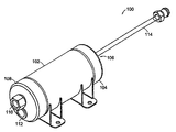
도1은 본 발명에 따른 반응 가스 필터의 양호한 실시예의 사시도이다.1 is a perspective view of a preferred embodiment of a reactive gas filter according to the present invention.
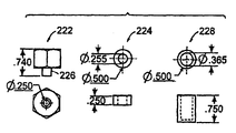
도2a 내지 도2w는 본 발명에 따른 반응성 가스 필터의 양호한 실시예의 다양한 상세도로서, 도2a 내지 도2i, 도2k 내지 도2o, 도2r 및 도2s, 그리고 도2u 내지 도2w는 축적도이고, 도2j, 도2p 내지 도2q, 그리고 도2t는 축적되어 도시될 필요가 없는 다양한 사시도이다.2A-2W are various detailed views of a preferred embodiment of a reactive gas filter according to the present invention, wherein FIGS. 2A-2I, 2K-2O, 2R and 2S, and 2U-2W are accumulation views. 2J, 2P-2Q, and 2T are various perspective views that need not be accumulated and shown.
도3a 내지 도3d는 도2a 내지 도2w의 반응성 가스 필터의 양호한 실시예의 다양한 상세도로서, 사각형 괄호 안에 기재된 치수는 밀리미터이고 괄호 안에 기재되지 않은 치수는 인치이다.3A-3D show various details of the preferred embodiment of the reactive gas filter of FIGS. 2A-2W, wherein dimensions in square brackets are millimeters and dimensions not in brackets are inches.
도4a는 본 발명에 따른 반응성 가스 필터의 다른 양호한 실시예의 사시도이다.4A is a perspective view of another preferred embodiment of a reactive gas filter according to the present invention.
도4b는 도4a의 가스 필터의 측면도이다.4B is a side view of the gas filter of FIG. 4A.
도5a는 본 발명에 따른 반응성 가스 필터의 다른 양호한 실시예의 사시도이다.5A is a perspective view of another preferred embodiment of a reactive gas filter in accordance with the present invention.
도5b 내지 도5d는 본 발명에 따른 반응성 가스 필터의 양호한 실시예의 축적에 따라 도시된 다양한 상세도로서, 괄호에 기재되지 않은 치수의 단위는 인치이다.Figures 5b-5d show various details of the accumulation of the preferred embodiment of the reactive gas filter according to the present invention, with the units not in parentheses being in inches.
도6은 본 발명에 따른 가스 필터의 압력 저하를 판단하기 위한 시스템의 개략적인 다이어그램이다.6 is a schematic diagram of a system for determining the pressure drop of a gas filter according to the present invention.
도7a 내지 도7c는 도1 내지 도5d에 도시된 가스 필터들과 사실상 유사한 가스 필터의 다양한 입구 기류 압력에서의 압력 저하 대 유동률의 플롯으로, 상기 플롯은 도6에 도시된 시스템과 사실상 유사한 시스템을 이용하여 판단된다.7A-7C are plots of pressure drop versus flow rate at various inlet airflow pressures of the gas filter that are substantially similar to the gas filters shown in FIGS. 1-5D, wherein the plot is a system substantially similar to the system shown in FIG. 6. It is judged using.
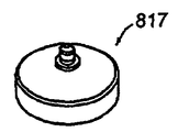
도8a 내지 도8v는 본 발명에 따른 반응성 가스 필터의 양호한 실시예의 다양한 상세도로서, 도8b 내지 도8g, 도8j 내지 도8l, 도8r 내지 도8t는 축적도이며, 도8a, 도8h 및 도8i, 도8m 및 도8n, 그리고 도8u 및 도8v는 축적되어 도시될 필요가 없는 다양한 사시도이다.8A-8V show various details of a preferred embodiment of a reactive gas filter in accordance with the present invention, wherein FIGS. 8B-8G, 8J-8L, 8R-8T are accumulation views, and FIGS. 8A-8H and FIG. 8i, 8m and 8n, and 8u and 8v are various perspective views that need not be accumulated and shown.
도9는 종래의 청정 건조 공기 필터에 대한 다양한 입구 기류 압력에서의 압력 저하 대 유동률의 플롯이다.9 is a plot of pressure drop versus flow rate at various inlet airflow pressures for a conventional clean dry air filter.
도10은 도8a 내지 도8v에 도시된 가스 필터에 사실상 유사한 가스 필터들에 대한 다양한 입구 기류 압력에서의 압력 저하 대 유동률의 플롯이다.FIG. 10 is a plot of pressure drop versus flow rate at various inlet airflow pressures for gas filters that are substantially similar to the gas filter shown in FIGS. 8A-8V.
도11a 내지 도11z, 도11aa 내지 도11az, 그리고 도11ba 내지 도11bz는 본 발명에 따른 반응성 가스 필터의 양호한 실시예의 다양한 상세도로서, 도11b 내지 도11f, 도11h 내지 도11j, 도11l 내지 도11n, 도11p 내지 도11r, 도11t 내지 도11v, 도11x 내지 도11z, 도11ab 내지 도11ad, 도11af 및 도11ag, 도11aj 내지 도11al, 도11an 내지 도11ap, 도11ar 내지 도11at, 도11av 내지 도11ax, 도11az, 도11bb, 도11bd, 도11bf, 도11bh 및 도11bj는 축적도이며, 도11a, 도11g, 도11k, 도11o, 도11s, 도11w, 도11aa, 도11ae, 도11ai, 도11am, 도11aq, 도11au, 도11ay, 도11ba, 도11bc, 도11be, 도11bg 및 도11bi는 축적되어 도시될 필요가 없는 다양한 사시도이다.11a-11z, 11aa-11az, and 11ba-11bz are various details of a preferred embodiment of a reactive gas filter in accordance with the present invention, FIGS. 11b-11f, 11h-11j, 11l-, 11n, 11p to 11r, 11t to 11v, 11x to 11z, 11ab to 11ad, 11af and 11ag, 11aj to 11al, 11an to 11ap, and 11ar to 11at. 11av to 11ax, 11az, 11bb, 11bd, 11bf, 11bh, and 11bj are accumulated views, and FIGS. 11a, 11g, 11k, 11o, 11s, 11w, 11aa, 11ae, 11ai, 11am, 11aq, 11au, 11ay, 11ba, 11bc, 11be, 11bg and 11bi are various perspective views that need not be accumulated and shown.
도12a 및 도12b는 도11a 내지 도11z, 도11aa 내지 도11az, 그리고 도11ba 내지 도11bz에 도시된 가스 필터와 사실상 유사한 가스 필터들에 대한 입구 기류 압력에서의 압력 저하 대 유동률의 플롯이다.12A and 12B are plots of pressure drop versus flow rate at inlet airflow pressures for gas filters that are substantially similar to the gas filters shown in FIGS. 11A-11Z, 11AA-11AZ, and 11BA-11B.
도13a 내지 도13c는 모트 코포레이션에 의해 공급되는 부품 번호 제2390804호인 고순도 동심 튜브 입자 필터에 대한 다양한 입구 기류 압력에서의 압력 저하 대 유동률의 플롯이다.13A-13C are plots of pressure drop versus flow rate at various inlet airflow pressures for a high purity concentric tube particle filter supplied by Mort Corporation, part number 2390804.
도14는 오염물을 판단하기 위한 장치의 실시예를 도시하는 도면이다.14 shows an embodiment of an apparatus for determining contaminants.
도15는 본 발명에 따른 내화 트랩의 실시예를 도시하는 도면이다.Fig. 15 is a diagram showing an embodiment of a fire resistant trap according to the present invention.
도16은 본 발명에 따른 필터 시스템의 실시예를 도시하는 도면이다.Figure 16 illustrates an embodiment of a filter system according to the present invention.
도17a 내지 도17c는 필터 시스템의 실시예에서 농축기로서 기능을 하는 장치의 개략적인 대표를 도시하는 도면이다.17A-17C show a schematic representation of a device functioning as a concentrator in an embodiment of a filter system.
도18은 본 발명에 따른 검출기 및 필터를 포함하는 시스템의 개략적인 대표를 도시하는 도면이다.18 shows a schematic representation of a system comprising a detector and a filter in accordance with the present invention.
도19는 오염물을 모니터링하기 위한 검출기의 실시예를 도시하는 도면이다.19 illustrates an embodiment of a detector for monitoring contaminants.
도20a 및 도20b는 본 발명의 실시예에 따른 검출기의 실시예들을 도시하는 도면이다.20A and 20B illustrate embodiments of a detector according to an embodiment of the present invention.
도21은 본 발명의 실시예에 따른 검출기를 이용하는 방법을 도시하는 도면이다.Figure 21 illustrates a method of using a detector according to an embodiment of the present invention.
도22는 휴대용 건조 샘플링 시스템의 실시예를 도시하는 도면이다.22 is a diagram illustrating an embodiment of a portable dry sampling system.
도23a는 본 발명의 실시예에 따른 파지형 건조 샘플링 장치의 개략적인 대표를 도시하는 도면이다.Fig. 23A is a diagram showing a schematic representation of a gripped dry sampling device according to an embodiment of the present invention.
도23b는 파지형 건조 샘플링 장치를 도시하는 도면이다.Fig. 23B is a diagram showing a gripped dry sampling device.
도24a 내지 도24c는 가스 공급 시에 오염물을 모니터링하기 위한 건조 샘플링 장치를 이용하는 방법을 도시하는 도면이다.24A-24C illustrate a method of using a dry sampling apparatus for monitoring contaminants in gas supply.
도25는 본 발명의 실시예에 따른 예시적인 컴퓨터의 개략적인 대표를 도시하는 도면이다.25 is a schematic representation of an exemplary computer in accordance with an embodiment of the present invention.
도26은 본 발명의 실시예에 따라 가스 공급 시에 오염물을 모니터링하는 개 략적인 대표를 도시하는 도면이다.FIG. 26 shows a schematic representation of monitoring contaminants upon gas supply in accordance with an embodiment of the present invention.
본 발명은 분자 오염물에 민감한 반도체 처리 툴 및 처리에 사용되는 반응 가스용 가스 필터에 관한 것이다. 가스 내의 오염물은 청정실 환경 그 자체를 포함한 다양한 원(source)에 의해 발생할 수 있다. 표1은 청정실 환경, 가령 예를 들면, 포토리소그래피 시스템을 사용하는 제작 환경에서의 다양한 종들을 나타내고 있다. 아세톤(acetone), 이소프로필 알코올(isopropyl alcohol) 및 낮은 분자 중량 실록산(siloxane)과 같은 낮은 분자 중량 종들이 제조 환경에 가장 널리 이용되고 있다. 또한, 청정 건조 공기와 같은, 소위 청정 가스는 반도체 처리에 부정적인 영향을 가하여 수율을 감소시키기에 충분한 농도에서 오염물을 함유할 수 있다. The present invention relates to semiconductor processing tools sensitive to molecular contaminants and gas filters for reactive gases used in processing. Contaminants in the gas can be caused by a variety of sources, including the clean room environment itself. Table 1 shows various species in a clean room environment, such as a production environment using, for example, a photolithography system. Low molecular weight species such as acetone, isopropyl alcohol and low molecular weight siloxanes are most widely used in the manufacturing environment. In addition, so-called clean gases, such as clean dry air, may contain contaminants at concentrations sufficient to adversely affect semiconductor processing and reduce yield.
광학계의 성능을 감쇄하는 경향이 큰 화합물은 높은 오염 계수 또는 높은 분자 중량을 가진 화합물이다. 이러한 예로서는 메톡시트리메틸 시레인(methoxytrimethyl silane), 트리메틸 시레인(trimethyl silane) 및 트리메틸 실란올(trimethyl silanol)을 포함할 수 있고, 이에 제한되지는 않는다. 이들 화합물은 표1에 이탤릭체로 나타나 있으며, 높은 분자 중량, 높은 오염 계수 및 무기 요소를 가진다. 광학 시스템에 부정적인 영향을 가하는 화합물은 시레인, 실록산 및 요오드산염(iodate), 특히 헥사메틸디실록산(hexamethyldisiloxane; HMDSO 또는 C6-실록산)과 같은 내화 화합물을 포함할 수도 있다. 내화 재료는 이에 제한되지는 않지만 인(P), 실리콘(Si), 황(S), 붕소(B), 주석(Sn), 알루미늄(Al)과 같은 비휘 발성 또는 반응성 산화물을 형성하는 원자를 포함하는 화합물이다. 이들 오염물은 딥 자외선(deep ultraviolet; DUV)에 노출될 수 있고 활성 산소 처리에 견디는 내화 화합물을 형성할 수 있다. Compounds with a high tendency to attenuate the performance of the optical system are compounds with high contamination coefficient or high molecular weight. Examples include, but are not limited to, methoxytrimethyl silane, trimethyl silane, and trimethyl silanol. These compounds are shown in italics in Table 1 and have high molecular weights, high contamination coefficients and inorganic elements. Compounds that negatively affect the optical system may include refractory compounds such as silanes, siloxanes, and iodates, especially hexamethyldisiloxane (HMDSO or C 6 -siloxane). Refractory materials include, but are not limited to, atoms that form nonvolatile or reactive oxides such as phosphorus (P), silicon (Si), sulfur (S), boron (B), tin (Sn), aluminum (Al) It is a compound. These contaminants may be exposed to deep ultraviolet (DUV) and form refractory compounds that withstand active oxygen treatment.
표1Table 1
광화학 분해 반응은 높은 에너지 광자가 유기 증기와 상호 작용할 경우 발생한다. 이들 반응은 다른 중성 및 비교적 불활성 유기 분자로부터 극 반응성 유리기를 형성한다. 기 형성이 가스상에서 또는 광학 요소의 표면상에서 발생하는 것과 관계없이, 최종 유리기는 대량의 유기 화합물을 형성하기 위해 반응할 수 있고, 이들 대량의 유기 화합물은 광학 요소를 오염시킬 수 있다. 심한 경우에는, 폴리머층이 광학 표면에 형성될 수 있다. 유기 종의 화학 성질과 광의 파장과의 관계는 광학 오염의 성질 및 강도에 영향을 미칠 수 있다. 예를 들면, I-라인 또는 365nm 파장 광은 청정실에서 통상 발견되지 않는 약간의 요오드 요소만을 분석하기에 효과적이다. 250 내지 150nm 선폭 장치를 제조하기 위해 통상적으로 딥 자외선(DUV) 리소그래피에 사용되는 248nm 파장 광은 할로겐화 유기물과 보다 효과적으로 반응하고, 심지어 대부분의 탄화수소와 상호 작용할 수 있다. 130nm 기하의 이하에 요구되는 193nm 광은 부유하는 또는 가스성 분자 유기 오염물의 광범위한 범위에 걸쳐 매우 효과적으로 반응한다.Photochemical decomposition reactions occur when high energy photons interact with organic vapors. These reactions form highly reactive free groups from other neutral and relatively inert organic molecules. Regardless of whether the group formation occurs in the gas phase or on the surface of the optical element, the final free group can react to form a large amount of organic compound, which can contaminate the optical element. In severe cases, a polymer layer may be formed on the optical surface. The relationship between the chemical nature of the organic species and the wavelength of light can affect the nature and intensity of optical contamination. For example, I-line or 365 nm wavelength light is effective for analyzing only a few iodine elements not normally found in clean rooms. 248 nm wavelength light, which is typically used in deep ultraviolet (DUV) lithography to fabricate 250-150 nm linewidth devices, reacts more effectively with halogenated organics and can even interact with most hydrocarbons. The 193 nm light required below 130 nm geometry reacts very effectively over a wide range of suspended or gaseous molecular organic contaminants.
리소그래피 노출 공구에 사용된 광의 파장이 감소함에 따라, 단위 광자당 에너지는 증가한다. 이들 점진적으로 높아지는 에너지를 갖는 광자들은 궁극적으로 광학 표면에 고착되는 반응성 물질(reactive species) 내로 반환(rendering)되는, 공통으로 존재하는 다수의 분자 물질이 보다 더 접합 붕괴의 기회를 갖는 위치에 있다. 157nm 광학 소자들은 이런 광의 파장이 불활성 청정 건식의 무산소(oxygen-free) 가스로 퍼지되도록, 통상 자유 작업 영역으로 불리는 최종 광학 소자와 웨이퍼 사이의 영역인 노출 영역을 필요로 하는 거의 모든 유기물에 산소 및 대기 습기를 더한 것으로 효과적으로 흡수되거나 상호 작용하기 때문에, 193nm 광학계보다 환경 조건에 더 민감하다.As the wavelength of light used in the lithographic exposure tool decreases, the energy per unit photon increases. These progressively higher energy photons are in a position where many of the commonly present molecular materials, which are eventually rendered into reactive species that adhere to the optical surface, have more chances of junction collapse. 157 nm optical devices require oxygen and oxygen in almost all organic materials that require an exposed area, which is the area between the wafer and the final optical device, commonly referred to as the free working area, so that this wavelength of light can be purged with an inert, clean, dry, oxygen-free gas. It is more sensitive to environmental conditions than 193nm optics because it effectively absorbs or interacts with the addition of atmospheric moisture.
본 발명의 바람직한 실시예에 따르면, 가스 필터는 필터 매체로 채워진 내부 챔버를 갖는 대체로 원통형인 하우징을 포함한다. 도1은 본 발명의 바람직한 실시예에 따른 가스 필터(100)의 외부 사시도이다. 하우징은 대체로 원통형 부분(102)과, 출구 포트(106)를 갖는 출구 단부(104)와, 입구 포트(110)를 갖는 입구 단부(108)를 포함한다. 하우징은 또한 내부 챔버를 필터 매체로 적재하기 위한 충전 포트(112)를 구비한다. 가스 필터는 또한 반응성 가스 공급원, 반응성 가스 라인, 매니폴드 또는 공구에 가스 필터의 연결을 용이하게 하는 예를 들면, 입구 조립체, 출구 조립체(114) 또는 모두를 포함할 수 있다.According to a preferred embodiment of the invention, the gas filter comprises a generally cylindrical housing having an inner chamber filled with filter media. 1 is an external perspective view of a
바람직하게는, 하우징 및 임의의 조립체는 본 발명의 이용에 적합한 316 스테인레스 강 및 304 스테인레스 강 등의 저황 금속으로 이루어진다. 하우징 및 임의의 조립체는 윤활제, 그리스, 먼지 등에 자유롭다는 것은 이해할 것이다. 따라서, 구성요소가 바람직하게는 초음파 세정기에서 예를 들면, 20% 수성 알코올 용매로 그리스가 제거되고 세정되는 것이 바람직하다. 이런 세정 방법은 당업계에 공지되어 있다. 또한, 가스 필터의 내부와 연통할 수 있는 모든 용접은 예를 들면 아르곤 등의 불활성 가스 환경에서 수행되는 것이 바람직하고, 바람직하게는 모든 용접은 무가스 용접의 발생을 용이하게 하기 위하여 불활성 가스 환경에서 수행된다. 바람직하게는, 모든 "용접물(welds)"은 가스이고, 텅스텐은 궤도 용접기로 이루어진 만곡된 표면 상에 용접되는 용접물이다. 사용 전에, 본 발명의 가스 필터는 24시간 내지 72시간 동안 상승된 온도 (예를 들면 100℃)에서, 예를 들면, 질소 등의 불활성 가스의 유동에 의해 퍼지되는 것이 또한 바람직하다. 사용 전에, 본 발명의 가스 필터는 여가될 가스의 습도와 평형을 이루도록 하는 것이 또한 바람직하다.Preferably, the housing and any assembly are made of low sulfur metals, such as 316 stainless steel and 304 stainless steel, suitable for use in the present invention. It will be appreciated that the housing and any assembly are free of lubricants, greases, dirt, and the like. Thus, the components are preferably removed and cleaned with an ultrasonic cleaner, for example with 20% aqueous alcohol solvent. Such cleaning methods are known in the art. In addition, all the welding which can communicate with the inside of the gas filter is preferably performed in an inert gas environment such as, for example, argon, and preferably all the welding is carried out in an inert gas environment to facilitate the generation of gas-free welding. Is performed. Preferably, all "welds" are gases and tungsten is a weld welded onto a curved surface consisting of an orbital welder. Prior to use, it is also preferred that the gas filter of the present invention is purged at a elevated temperature (eg 100 ° C.) for 24 to 72 hours, for example by the flow of an inert gas such as nitrogen. Prior to use, it is also preferred that the gas filter of the invention is balanced with the humidity of the gas to be spared.
내부 챔버 내의 필터 매체는 예를 들면 펠릿(pellet) 또는 그래뉼(granule) 형태로 불활성 폴리머, 탄소, 활성 탄소 및 무기물을 포함할 수 있다. 바람직하게는, 펠릿 또는 그래뉼은 약 16 U.S. 메쉬 내지 50 U.S. 메쉬 범위의 평균 메쉬 사이즈를 갖는다. 이들 펠릿들 또는 그래뉼들은 하나 이상의 유형의 유기 및 무기 성분의 흡수를 촉진하도록 화학적으로 활성 또는 화학적으로 촉매 필터링 물질로 취급되지 않거나 취급되고, 예를 들면, 브롬화수소산(hydrobromic acid), 질산 (nitric acid), 황산(sulfuric acid), 인산(phosphoric acid), 염산(hydrochloroc acid) 등의 산과, 암모니아, 암모니아 수산화물(ammonia hydroxide), 테트라메틸암모니아 수산화물(tetramethylammonia hydroxide), 트림에틸아민(trimethylamine), 트리에틸아민(triethylamine), 헥사메틸디실라잔(hexamethyldisilazane), NMP, 시클로헥실아민(cyclohexylamine), 디에틸아미노에탄올(diethylaminoethanol), 메틸라아민(methylaamine), 디메틸아민(dimethylamine), 에탄올아민(ethanolamine), 모폴린(morpholine), 150℃ 이상의 끓는점을 갖는 실리콘 및 탄화수소 등의 응축물(condensable) 등의 염기와, 보론(보통 붕산), 인(보통 유기인산 화합물) 및 비소(보통 비산염) 등의 도펀트(dopant)를 포함한다.The filter media in the inner chamber may comprise inert polymer, carbon, activated carbon and inorganics, for example in the form of pellets or granules. Preferably, the pellet or granule is about 16 U.S. Mesh to 50 U.S. Have an average mesh size in the mesh range. These pellets or granules are not treated or treated as chemically active or chemically catalytically filtering materials to promote absorption of one or more types of organic and inorganic components, for example hydrobromic acid, nitric acid ), Acids such as sulfuric acid, phosphoric acid, hydrochloroc acid, ammonia, ammonia hydroxide, tetramethylammonia hydroxide, triethylamine, triethyl Amine (triethylamine), hexamethyldisilazane, NMP, cyclohexylamine, diethylaminoethanol, methylaamine, dimethylamine, ethanolamine, Bases such as morpholine, condensables such as silicon and hydrocarbons having a boiling point of 150 ° C. or higher, boron (usually boric acid), phosphorus (bovine) Common organophosphate compounds) and dope (such as arsenic).
아주 다양한 화학적으로 활성 또는 화학적으로 촉매 필터링 물질은 필터 매체를 형성하기 위해 펠릿 또는 그래뉼로 사용될 수 있다. 기본 아민의 흡수를 위한 물질의 예는 제한적이지는 않지만 인산(H3PO4), 술폰화된 스티렌 다이비닐 벤젠(sulfonated styrene divinyl benzene)을 포함한다. (예를 들면 황산 등의) 산의 흡수를 위한 물질의 예는 제한적이지는 않지만 탄산 칼륨(K2CO3), 4기 아민을 포함한다. 산 및 염기에 더하여, 임의의 성분들은 HMDSO 등의 포토리소그래피 시스템 내의 특별한 것에 관한 것 중에 있다. HMDSO의 흡수를 위한 물질의 예는 제한적이지는 않지만 비처리 그래뉼 활성 탄소(GAC), 제올라이트를 포함한다. A wide variety of chemically active or chemically catalytic filtering materials can be used as pellets or granules to form filter media. Examples of materials for absorption of basic amines include, but are not limited to, phosphoric acid (H 3 PO 4 ), sulfonated styrene divinyl benzene. Examples of substances for absorption of acids (such as sulfuric acid) include, but are not limited to, potassium carbonate (K 2 CO 3 ), quaternary amines. In addition to acids and bases, certain components are of particular relevance to photolithography systems such as HMDSO. Examples of materials for absorption of HMDSO include, but are not limited to, untreated granule activated carbon (GAC), zeolites.
바람직한 실시예에 따르면, 필터 매체는 약 1200 m2/g의 그램당 최소 표면 면적 및 약 0.45 내지 약 0.50 g/ml 범위의 밀도를 갖는 GAC와, 약 1000 m2/g의 그램당 최소 표면 면적 및 약 0.66 내지 약 0.69 g/ml 범위의 밀도를 갖는 인산 처리 GAC와, 약 1000 m2/g의 그램당 최소 표면 면적 및 약 0.7 내지 약 0.9 g/ml 범위의 밀도를 갖는 탄산 칼륨 처리 GAC를 포함한다.According to a preferred embodiment, the filter media has a GAC having a minimum surface area per gram of about 1200 m 2 / g and a density ranging from about 0.45 to about 0.50 g / ml, and a minimum surface area per gram of about 1000 m 2 / g. And a phosphate treated GAC having a density ranging from about 0.66 to about 0.69 g / ml, and a potassium carbonate treated GAC having a minimum surface area per gram of about 1000 m 2 / g and a density ranging from about 0.7 to about 0.9 g / ml. Include.
오염 제어를 위한 추가적인 화학적으로 활성 또는 화학적으로 촉매 필터링 물질은 "다공성 강산 폴리머 및 물리적 흡수 매체를 채용한 필터(Filters Employing Porous Strongly Acidic Polymers and Physical Adsorption Media)"라는 명칭 하에 2002년 7월 26일에 출원된 미국 출원 제10/205,703호, "반도체 제조 및 유사한 민감 공정의 보호(Protection of Semiconductor Fabrication and Similar Sensitive Processes)"라는 명칭 하에 2001년 10월 1일에 출원된 미국 출원 제09/969,116호, 및 "가스 샘플 내의 염기 오염물의 감지(Detection of Base Contaminants In Gas Samples)"라는 명칭 하에 2001년 2월 14일에 출원된 미국 출원 제09/783,232호에 기술되어 있고, 상기 참조된 출원들의 전체 교시는 그 전체가 참조에 의해 본 명세서에 합체되어 있다.An additional chemically active or chemically catalytic filtering material for contamination control was developed on July 26, 2002 under the name "Filters Employing Porous Strongly Acidic Polymers and Physical Adsorption Media". U.S. Application No. 09 / 969,116, filed Oct. 1, 2001, entitled U.S. Application No. 10 / 205,703, "Protection of Semiconductor Fabrication and Similar Sensitive Processes." And US Application No. 09 / 783,232, filed Feb. 14, 2001, entitled "Detection of Base Contaminants In Gas Samples," and the entire teaching of the above referenced applications. Is incorporated herein by reference in its entirety.
도2a 내지 도2w는 청정 건식 공기(CDA) 등의 반응성 가스로 사용되기 위한 본 발명에 따른 가스 필터의 바람직한 실시예의 상세도를 나타낸 것이다. 도2a 내지 도2c는 대체로 원통형인 중앙 부분(202)을 갖는 가스 필터(200)의 외부 축척도를 도시한 것이다. 출구 단부(204)는 도2c에 도시된 단부이고 출구 포트(206)를 갖는다. 출구 단부(204)는 또한 가스 라인, 매니폴드 등에 연결을 용이하게 하기 위한 출구 인터페이스 조립체(208, 210, 212)를 포함할 수 있다. 입구 단부(214)는 도2b에 도시된 단부이고 입구 포트(216)를 포함하며 충전 포트(220)를 또한 포함할 수 있다. 입구 단부(214)는 가스 라인, 매니폴드 등에 연결을 용이하게 하기 위한 입구 인터페이스 조립체(218)를 포함할 수 있고, 중앙 부분(202)은 장착 브래킷(219)을 포함할 수 있다.2A-2W show detailed views of a preferred embodiment of a gas filter according to the present invention for use as a reactive gas such as clean dry air (CDA). 2A-2C show an external scale view of
도2d 내지 도2f는 도시된 브래킷되지 않은 치수가 바람직한 실시예에 대한 것이고 인치 단위로 나타낸 인터페이스 조립체를 갖는 입구 단부(214)의 축척도를 도시한 것이다. 도2d는 입구 포트(216 및 충전 포트(220)를 갖는 입구 단부(214)의 단부도를 도시한 것이다. 도2e는 입구 인터페이스 조립체(222, 224, 226)의 구성요소 및 바람직한 실시예에서 부 조립체(224)에 용접된 다공성 니켈 컵 입자 필터(228)를 도시한 것이다. 도2e는 입구 인터페이스 조립체를 갖는 입구 단부(214) 및 플러그(232)를 갖는 충전 포트 조립체(230)의 숨김 선 측면도를 도시한 것이다. 도2h는 조립체(215)를 갖는 입구 단부의 단부도를 도시한 것이고, 도2i는 인치 단위이고 mm로 제곱 브래킷된 치수이다. 단면도는 입구 입자 필터(228)가 연장하는 내부 챔버(201)의 일부를 또한 도시한 것이다. 한편, 도2j는 조립체(215)를 갖는 입구 단부의 분해 조립체 도면(필수적으로 축척되지 않음)을 도시한 것이다.2D-2F show a scaled view of the
도2k 내지 도2m은 도시된 브래킷되지 않은 치수가 바람직한 실시예에 대한 것이고 인치 단위인 인터페이스 조립체(208, 210, 212)를 갖는 출구 단부(202)의 축척도를 도시한 것이다. 도2k는 출구 포트(206)를 갖는 출구 단부(204)의 단부도를 도시한 것이다. 도2m 및 도2l은 출구 인터페이스 조립체(208, 210, 212)가 구 성요소 및 바람직한 실시예에서 부 조립체(234)에 용접된 다공성 니켈 컵 입자 필터(226)를 도시한 것이다. 도2l은 튜브(208), 플러그(210)를 갖는 인터페이스 피팅(212)을 갖는 출구 인터페이스 조립체를 갖는 출구 단부(204)의 숨김 선 측면도이다. 도2n은 도2o의 단부 도면의 GG를 따른 단면도를 도시한 것이고, 도2o는 출구 인터페이스 조립체(233)를 갖는 출구 단부의 단부도를 도시한 것이다. 도2n에서의 브래킷되지 않은 치수는 인치 단위이다. 도2n의 단면도는 출구 입자 필터(236)가 연장되는 내부 챔버(201)의 다른 부분을 또한 도시한 것이다. 한편, 도2p는 인터페이스 조립체(233)를 갖는 출구 단부의 사시도(필수적으로 축척되지 않음)를 도시한 것이다.2K-2M show a scaled view of the
도2q 내지 도2s는 모든 브래킷되지 않은 치수들은 인치 단위로 주어지는 대체로 원통형 부분(202)의 상세도를 도시한 것이다. 도2q는 대체로 원통형 부분의 사시도(필수적으로 축척되지 않음)를 도시한 것이다. 도2r 및 도2s는 각각 단부도 및 선 HH를 따른 단면도를 도시하도록 축척된다. 도2s의 단면도는 내부 챔버(201)의 잔여 부분을 도시한 것이다.2Q-2S show detailed views of a generally
도2t 내지 도2w는 장착 브래킷(219)의 상세도를 도시한 것이고, 도2t는 필수적으로 축척되지 않은 사시도이고, 도2u 내지 도2w는 브래킷되지 않은 치수는 인치 단위인 축척된 평면도이다.2T-2W show detailed views of mounting
바람직한 실시예에서, 도2a 내지 도2w의 구성요소, 물질 및 하드웨어는 다음과 같다.In a preferred embodiment, the components, materials, and hardware of FIGS. 2A-2W are as follows.
0.083", 2.5" 외측 직경(OD) 스테인레스 강(SS) 튜빙, 202;0.083 ", 2.5" outer diameter (OD) stainless steel (SS) tubing, 202;
2.5" SS 파이프 캡 [스웨질락(Swagelok) B16W-CAP-37-101], 204;2.5 "SS pipe caps (Swagelok B16W-CAP-37-101), 204;
1.4" 인치 OD SS 튜빙, 208;1.4 "inch OD SS tubing, 208;
4" VCR 짧은 튜브 용접 글랜드 (스웨질락 6LV-4-VCT-3S-4TB3), 210;4 "VCR short tube weld gland (Swezillak 6LV-4-VCT-3S-4TB3), 210;
1.4" VCR 메일 글랜드 너트 (스웨질락 SS-4-VCR-4), 212;1.4 "VCR mail gland nut (Swezilock SS-4-VCR-4), 212;
BSP 피팅 (스웨질락 -4TA-7-4RT), 218;BSP fitting (Swezilac-4TA-7-4RT), 218;
0.06-304 SS 벽 용접 브래킷, 219;0.06-304 SS wall welding brackets, 219;
BSP 피팅 -4-TA-7-4RT (스웨질락), 222;BSP fitting -4-TA-7-4RT (Swezilac), 222;
니켈(Ni) 고순도 입자 필터 컵, Mott Corp. (부품 번호 제1204380호), 228;Nickel High Purity Particle Filter Cups, Mott Corp. (Part No. 1204380), 228;
라운드 스톡에서 제조된 필 스파우트(Fill Spout), Tapped 1/4-20, 230;Fill Spout, Tapped 1 / 4-20, 230 made from round stock;
기계 가공된 와셔, 전이부로 사용됨, 224;Machined washers, used as transitions, 224;
2.5" SS 필 스파우트를 갖는 파이프 캡 (스웨질락 B16W-CAP-37-101), 214;Pipe cap with 2.5 "SS fill spout (Swezillak B16W-CAP-37-101), 214;
BSP 피팅 -4-TA-7-4RT (스웨질락), 222;BSP fitting -4-TA-7-4RT (Swezilac), 222;
1/4" 20 SS 파이프 플러그 (스웨질락), 232;1/4 "20 SS pipe plug (Swezilock), 232;
Ni 고순도 입자 필터 컵, Mott Corp. 부품번호 제1204380호), 236;Ni High Purity Particle Filter Cup, Mott Corp. Part No. 1204380), 236;
1/4" OD SS 튜빙, 길이부에 기계 가공됨, 238;1/4 "OD SS tubing, machined to length, 238;
4" VCR 짧은 튜브 용접 글랜드 (스웨질락 6LV-4VCT-3S-4TB3), 242;4 "VCR short tube weld gland (Swezillak 6LV-4VCT-3S-4TB3), 242;
1/4" VCR 메일 글랜드 너트 (스웨질락 SS-4-VCR-4), 240; 및1/4 "VCR mail gland nut (Swezilock SS-4-VCR-4), 240; and
기계 가공된 와셔, 전이부로 사용됨, 234.Machined washers, used as transitions, 234.
도3a 내지 도3d는 입구 조립체(215)를 갖는 입구 및 출구 조립체(233)를 갖는 출구를 포함하는 도2a 내지 도2w의 반응성 가스 필터(200)의 바람직한 실시예의 다양한 상세도를 도시한 것이다. 도3a 내지 도3d에서, 제곱 브래킷 치수는 mm 단위이고 브래킷되지 않은 치수는 인치 단위이다. 바람직한 실시예 300에서, 가스 필터(200)는 필터에 대해 그림자 박스로 도시된 3차원 푸트프린트(302) 내에 끼움 결합된다. 3A-3D show various details of the preferred embodiment of the
다른 바람직한 실시예에 따르면, 본 발명의 가스 필터는 실질적으로 도4a 내지 도4d, 및 도5a 내지 도5d에 도시된 바이다. 도4a 내지 도4b는 어두운 외부도를 나타내고, 도5a 내지 도5d는 보다 상세한 도면을 제공한다. 본 발명의 바람직한 실시예에 따르면, 가스 필터(400)는 필터 매체로 채워진 내부 챔버를 갖는 대체로 원통형 하우징을 포함한다. 하우징은 대체로 원통형 부분(402)과, 출구 포트(406)를 갖는 출구 단부(404)와, 입구 포트(410)를 갖는 입구 단부(408)를 포함한다. 입구 포트(410) 및 출구 포트(406)는 입구 포트(410)가 대체로 원통형 부분(402)의 축에 어긋나게 위치되고 출구 포트(406)가 대체로 원통형 부분(402)의 축 상에 위치될 경우, 동일한 축을 나누지는 않는다. 하우징은 필터 매체로 내부 챔버를 적재하기 위한 충전 포트(412)를 또한 가질 수 있다. 가스 필터는 반응성 가스 공급원, 반응성 가스 라인, 매니폴드 또는 공구에 가스 필터의 연결을 용이하게 하기 위해 예를 들면, 입구 조립체, 출구 조립체(414) 또는 모두를 또한 포함할 수 있다. 또한, 가스 필터를 통해 가스 유동의 제시된 방향을 지시하는 화살표인 제품 라벨(403)에 대한 개념이 도시되어 있다. According to another preferred embodiment, the gas filter of the present invention is substantially as shown in FIGS. 4A-4D and 5A-5D. 4A-4B show dark external views, and FIGS. 5A-5D provide a more detailed view. According to a preferred embodiment of the invention, the
도5a는 본 발명의 바람직한 실시예에 따른 가스 필터(500)의 외부 사시도이다. 하우징은 대체로 원통형 부분(502)과, 출구 포트(506)를 갖는 출구 단부(504) 와, 입구 포트(516)를 갖는 입구 단부(514)를 포함한다. 가스 필터는 반응성 가스 공급원, 반응성 가스 라인, 매니폴드 또는 공구에 가스 필터의 연결을 용이하게 하기 위해 예를 들면, 입구 인터페이스 조립체(518) 및 출구 인터페이스 조립체(508)를 또한 포함할 수 있다. 하우징은 내부 챔버를 충전 및 챔버의 견고한 밀봉을 촉진하기 위해 충전 포트 조립체(521)로 충전 매체를 내부 챔버에 적재하기 위한 충전 포트(520)를 또한 가질 수 있다. 또한, 가스 필터(500)는 장착 브래킷을 포함할 수 있다. 도5b 내지 도5d는 대체로 원통 중앙 부분(502)을 갖는 가스 필터(501)의 외부 축척도를 도시한 것이다. 출구 단부(504)는 도5d에서의 단부 상(end-on)에 도시되고, 출구 포트(506)를 갖는다. 출구 단부(504)는 가스 라인, 매니폴드 등에 연결을 용이하게 하기 위해 출구 인터페이스 조립체(508, 510, 512)를 또한 포함할 수 있다. 입구 단부(514)는 도5c에 단부 상에 도시되고, 입구 포트(516)를 포함하며, 충전 포트(520)를 또한 포함할 수 있다. 입구 단부(516)는 가스 라인, 매니폴드 등에 연결을 용이하게 하기 위해 입구 인터페이스 조립체(518)를 포함할 수 있고, 중앙 부분(502)은 장착 브래킷(519)를 포함할 수 있다. 도5b 내지 도5d의 가스 필터(501)의 구성요소의 다양한 상세는 출구 단부(504) 상의 출구 포트(506)의 위치를 제외하고는, 도2a 내지 도2w와 대체로 유사하다. 도5a 내지 도5d에 도시된 바와 같이, 출구 포트(506)는 출구 단부(504) 내의 중심에 있고, 따라서 중앙 부분(502)의 축과 일치하는 축을 가진다. 입구 포트(516)에 대해 출구 포트(506)의 이런 위치는 가스 필터(501)를 통해 가스 유동이 통과하는 것을 방지하는 것을 보조한다는 것으로 믿어진다.5A is an external perspective view of a
본 발명의 바람직한 실시예에 따르면, 대체로 도2a 내지 도2w 및 도4a 내지 도5d에 따르는 가스 필터가, 처리된 및 비처리된 GAC의 평균 메쉬 크기가 약 20 U.S. 메쉬에서 약 50 U.S. 메쉬까지의 범위 내에 있을 경우, 내부 챔버가 예를 들어 약 80%의 GAC, 약 10%의 산 처리된(acid treated) GAC, 및 약 10%의 염기 처리된(base treated) GAC를 포함하는 필터 매체로 충전될 때, 개선된 압력 저하 및 암모니아 농도와 이산화 황 농도가 각각 약 10 ppbv 이하 및 5 ppbv 이하인 입력 기류에 대해 암모니아와 이산화 황에 대해 약 1 ppbv 미만의 농도를 갖는 출력 기류를 제공할 수 있다. 바람직한 실시예에 따르면, 가스 필터는 HMDSO를 포함하는 약 100 ppbv 이하의 응축 가능한 총 유기 농도의 입력 기류에 대해 HMDSO의 약 10 ppbv 미만의 응축 가능한 총 유기 농도를 갖는 출력 기류를 또한 제공한다.According to a preferred embodiment of the present invention, the gas filter according to FIGS. 2A-2W and 4A-5D generally has an average mesh size of treated and untreated GACs of about 20 U.S. About 50 U.S. in the mesh If within the range to the mesh, the inner chamber may comprise, for example, about 80% GAC, about 10% acid treated GAC, and about 10% base treated GAC When filled with media, it will provide improved pressure drop and output airflow with concentrations of less than about 1 ppbv for ammonia and sulfur dioxide for input airflows of up to about 10 ppbv and up to 5 ppbv respectively. Can be. According to a preferred embodiment, the gas filter also provides an output airflow having a condensable total organic concentration of less than about 10 ppbv of HMDSO relative to an input airflow of less than about 100 ppbv of condensable total organic concentration comprising HMDSO.
바람직한 실시예에서, 필터 매체는, 약 20 U.S. 메쉬 내지 약 50 U.S. 메쉬의 범위 내의 평균 메쉬 크기인 약 80% GAC, 약 20 U.S. 메쉬 내지 약 50 U.S. 메쉬 범위 내의 평균 메쉬 크기인 약 10% 탄산 칼륨(potassium carbonate) 처리 GAC, 및 약 20 U.S. 메쉬 내지 약 50 U.S. 메쉬 범위 내의 평균 메쉬 크기인 약 10% 인산 처리 GAC를 포함한다.In a preferred embodiment, the filter medium is about 20 U.S. Mesh to about 50 U.S. About 80% GAC, about 20 U.S. mean mesh size within the mesh's range. Mesh to about 50 U.S. An average mesh size within the mesh range of about 10% potassium carbonate treated GAC, and about 20 U.S. Mesh to about 50 U.S. About 10% phosphate treated GAC, which is an average mesh size within the mesh range.
도6은 본 발명에 따르는 가스 필터의 압력 저하를 판단하기 위한 시스템의 개략도이다. 입구 기류(602)는 압력 조정기(604)에 의해 제어된다. 양호하게는, 입구 가스는 압축된 청정 건조 공기이지만, 질소 등의 불활성 가스도 가스 필터의 압력 저하를 시험하는데 적합하다. 입구 기류는 우선 탄소 세정 장치(606)를 통과하고, 가스 필터(608)에 걸친 압력 저하가 가스 필터(608) 입구와 출구 기류 사이 의 압력차를 측정하도록 설정된 압력 게이지(610)로 측정된다. 출구 기류의 압력이 압력 게이지(612)로 측정되어 유량계(614)에 의해 측정된 출력 기류 유량을 표준 분당 리터(standard liters per minute)로 변환하는 것을 용이하게 한다. 이러한 시험에서, 출력 기류는 대기(616)로 배기된다.6 is a schematic diagram of a system for determining a pressure drop of a gas filter according to the present invention.
도7a 내지 도7c는, 도5a 내지 도5d의 바람직한 실시예와 실질적으로 유사한, 본 발명에 따르는 가스 필터에 대한 압력 저하 시험 결과를 도시한다. 도7a와 도7b에 도시된 시험 결과는 필터 매체가 없는 가스 필터에 관한 것이고, 도7c의 시험 결과는 필터 매체를 구비한 가스 필터에 관한 것이다. 본 발명의 다른 바람직한 실시예에 대한 시험들은, 약 20 U.S. 메쉬 내지 약 50 U.S. 메쉬 범위 내의 평균 메쉬 크기인 약 80% GAC, 약 20 U.S. 메쉬 내지 약 50 U.S. 메쉬 범위 내의 평균 메쉬 크기인 약 10%의 탄산 칼륨 처리 GAC, 및 약 20 U.S. 메쉬 내지 약 50 U.S. 메쉬 범위 내의 평균 메쉬 크기인 약 10% 인산 GAC를 포함하며, 부피(도5a 내지 도5d의 실시예의 내부 챔버의 예상 부피)가 약 0.4 리터인 필터 매체에 대해 약 6.9 ㎪ (1 psi) 내지 약 20.68 ㎪ (3 psi) 범위 내의 부가적인 압력 저하를 예상한다.7A-7C show the results of a pressure drop test for the gas filter according to the invention, substantially similar to the preferred embodiment of FIGS. 5A-5D. The test results shown in FIGS. 7A and 7B relate to gas filters without filter media, and the test results of FIG. 7C relate to gas filters with filter media. Tests for other preferred embodiments of the present invention, about 20 U.S. Mesh to about 50 U.S. Average mesh size within the mesh range of about 80% GAC, about 20 U.S. Mesh to about 50 U.S. About 10% potassium carbonate treated GAC, and an average mesh size within the mesh range, and about 20 U.S. Mesh to about 50 U.S. From about 1 psi to about 6.9 for a filter medium comprising about 10% phosphoric acid GAC, which is an average mesh size within the mesh range, and a volume (estimated volume of the internal chamber of the embodiment of FIGS. 5A-5D) of about 0.4 liters Expect additional pressure drop within the range of 3 psi.
도7a 및 도7b를 참조하면, 도7a는 압력 저하에 대한 여러 입구 기류 압력에서의 (slpm으로 나타낸) 출구 유량의 그래프(700)이며, 도7B는 출구 유량에 대한 여러 입구 기류 압력에서의 (표준 시간당 피트 세제곱인 "cfh"로 나타낸) 출구 유량의 그래프(701)이다. 도7a와 도7b에 도시된 데이터가 표2에 표로 작성되었다. 도7a와 도7b는 약 206 ㎪ (30 psi, 2.06 bar)에서의(702, 703), 약 413 ㎪ (60 psi, 4.13 bar)에서의(704, 705), 약 620 ㎪ (90 psi, 6.20 bar)에서의(706, 707), 약 689 ㎪ (100 psi, 6.89 bar)에서의(708, 709) 입구 가스 압력의 압력 저하의 변량(variation)을 나타내며, 입구 유량의 범위에서의 이들 입구 압력에서의 가스 필터의 성능을 나타낸다.Referring to Figures 7A and 7B, Figure 7A is a
표2Table 2

도7c는 (bar로 나타낸) 여러 입구 기류 압력에서의 (slpm으로 나타낸) 출구 유량에 대한 압력 저하의 그래프(710)이다. 도7c에 도시된 데이터는 표3에 표로 작성되었으며, 각 측정에서의 오차는 ±5%로 추정된다. 도7c는 약 206 ㎪(2.06 bar)에서의(712), 약 413 ㎪ (4.13 bar)에서의(714), 약 620 ㎪(6.20 bar)에서의(716), 약 689 ㎪(6.89 bar)에서의(718), 및 약 750 ㎪(7.5 bar)에서의(720) 입구 가스 압력에 대한 압력 저하의 변량과, 출구 유량의 범위에서의 이들 입구 압력에서의 가스 필터의 성능을 나타낸다. 또한, 그래프(710)는 206 ㎪(2.06 bar) 데이터(722), 413 ㎪ (4.13 bar) 데이터(724), 620 ㎪(6.20 bar) 데이터(726), 689 ㎪(6.89 bar) 데이터(728), 및 750 ㎪(7.5 bar) 데이터(730)에 대한 폴리노미알 피트(polynomial fit)를 도시한다.7C is a
표3Table 3

도8a 내지 도8v는 청정 건조 공기(CDA)와 같은 반응성 가스를 사용한 본 발명에 따르는 가스 필터의 다른 바람직한 실시예의 상세한 도면들이다. 도8a는 축척으로 나타낼 필요가 없는 가스 필터(800)의 등각도(isometric view)이며, 도8b 내지 도8g는 괄호가 없는 치수는 인치이고 대괄호로 나타낸 치수는 ㎜인 외부 축척도이다. 가스 필터(800)는 대체로 원통형인 중심 부분(802)과 출구 포트(806)를 갖는 출구 단부(804)를 포함하며, 가스 라인, 매니폴드 등으로의 연결을 용이하게 하는 출구 인터페이스 조립체(808)를 더 포함할 수 있다. 입구 단부(814)는 도8d 내지 도8g에서 도시된 엔드-온(end-on)이며, 입구 포트(816)를 포함하며, 충전 포트(820)를 포함할 수도 있다. 입구 단부(814)는 가스 라인, 매니폴드 등으로의 연결을 용이하게 하는 입구 인터페이스 조립체(818)를 포함할 수 있으며, 중심 부분(802)은 장착 브래킷(819)을 포함할 수 있으며, 충전 포트(820)는 필터 매체를 추가하는 것 및 충전 포트를 쉽게 밀봉하는 것을 용이하게 하는 충전 포트 조립체(821)를 포함할 수 있다.8A-8V are detailed views of another preferred embodiment of a gas filter according to the present invention using a reactive gas such as clean dry air (CDA). FIG. 8A is an isometric view of
도8h는 축척으로 나타낼 필요가 없는, 가스 필터(800)의 조립체(815)를 갖는 입구 단부의 등각도이며, 도8i는 축척으로 나타낼 필요가 없는, 출구 인터페이스 조립체를 갖는 출구 단부와 대체로 동일한 충전 포트 없는 입구 단부의 등각도(817)이다. 도8j 내지 도8l은 인터페이스 조립체(815)를 갖는 입구 단부의 축척도이다. 도8j는 입구 인터페이스 조립체(818)와 충전 포트 조립체(821)를 갖는 입구 단부(814)의 히든-라인(hidden-line) 측면도이며, 또한, 다공성 니켈 컵 입구 입자 필터를 도시한다. 도8k는 조립체(815)를 갖는 입구 단부의 단부도이며, 도8l은 도8k의 AA를 따르는 단면도를 나타낸다. 또한, 도8k는 안쪽으로 입구 입자 필터(828)가 연장되는 내부 챔버(801)의 일부를 도시한다. 도8m은 (축척으로 나타낼 필요가 없는,) 조립체(815)를 갖는 입구 단부의 전개된 조립체 도면이다. 도8m은 입구 단부(814)의 입구 포트(816) 안으로의 입구 인터페이스 조립체(818), 및 충전 포트(820)에 대한 충전 포트 조립체(812)의 구성 요소(822, 825)의 조립체를 나타낸다.FIG. 8H is an isometric view of the inlet end with the
출구 단부(804)와 출구 인터페이스 조립체(808)는, 예를 들어 도81에 도시된 바와 같이, 각각 입구 단부 및 입구 인터페이스 조립체와 대체로 동일하다.The
도8n 내지 도8p는 대체로 원통형인 부분(802)의 세부 사항을 도시하며, 여기서, 괄호가 없는 치수는 모두 인치를 나타낸다. 도8n은 (축척으로 나타낼 필요가 없는,) 대체로 원통형인 부분(802)의 등각도를 도시한다. 도8o와 도8p는 축척으로 나타낸 단부도 및 절취 측면도를 각각 나타낸다. 절취 도면 도8p는 내부 챔버(801)의 일부분을 도시한다.8N-8P show details of generally
도8q 내지 도8t는 장착 브래킷(819)의 세부 사항을 도시하는데, 도8q는 축척 으로 나타낼 필요가 없는 등각도이며, 도8r 내지 도8t는 괄호가 없는 치수가 인치를 나타내는 축척하여 도시한 평면도이다.8Q-8T show details of the mounting
도8u 및 도8v는 축척하여 도시할 필요가 없는, 가스 필터(800)의 다른 등각 조립체 도면이다. 도8u는 대체로 원통형인 부분(802) 내의 내부 챔버(801)의 일부분 및 출구 단부(804)를 도시한 전개된 조립체 도면을 나타낸다. 또한, 도8u는 출구 입자 필터(836)의 도면을 제공한다. 도8v는 본 발명에 따르는 가스 필터(800)의 바람직한 실시예의 등각도와, 플러그(831)를 갖는 입구 인터페이스 조립체(816) 및 플러그(833)를 갖는 (도면에서는 숨겨진) 출구 인터페이스 조립체의 전개된 조립체 도면을 도시한다.8U and 8V are other conformal assembly views of the
바람직한 실시예에서, 도8a 내지 도8v의 구성 요소, 재료, 및 하드웨어는 다음과 같다.In a preferred embodiment, the components, materials, and hardware of FIGS. 8A-8V are as follows.
2.11 ㎜ (0.083 인치), 10.16 ㎝ (4 인치) OD 스테인레스강(SS) 파이프(809)2.11 mm (0.083 in), 10.16 cm (4 in) OD stainless steel (SS) pipe (809)
10.16 ㎝ (4 인치) OD 파이프 캡 SS(804)10.16 cm (4 in) OD pipe cap SS (804)
0.06-304 SS 벽 용접 브래킷(819)0.06-304 SS Wall Weld Bracket (819)
10.16 ㎝ (4 인치) OD 파이프 캡 SS 충전 주둥이 구멍(814)10.16 cm (4 inch) OD Pipe Cap SS Filling Spout Hole (814)
고순도 입자 필터, 모트 코포레이션(Mott Corporation) (부품 번호)(828)High Purity Particle Filter, Mott Corporation (Part Number) (828)
스와겔록 8-VCR 그랜드 피팅(Swagelok 8VCR Gland Fitting) SS(827)Swagelok 8-VCR Gland Fitting SS (827)
스와겔록 8-VCR 암나사 SS(825)Swagelok 8-VCR Female Thread SS (825)
고순도 입자 필터, 모트 코포레이션(Mott Corporation) (부품 번호)(836)High Purity Particle Filter, Mott Corporation (Part Number) (836)
비교를 위해, 도9는 본 발명에 따르지 않는, (slpm으로 나타낸) 출구 유량에 대한 가스 필터(CDA 여과통)에 대한 여러 입구 가스 스트림 압력에서의 (psi로 나타낸) 압력 저하의 그래프이다. 도9는 620 ㎪(90 psi)의 입구 가스 압력과 여과통 외부의 0.003 미크론 입자 필터를 갖는 [63.5 ㎜ (2.5 인치) 폭에 30.5㎝ (12 인치) 길이의] CDA 여과통에 대한 도면(900)을 도시하며, 여기서, 마름모(902)는 실제 데이터 점이며 선(904)은 데이터의 [피팅된 선(906)용 공식이 그래프 상부에 주어져 있는] 리니어 피트(linear fit)이다.For comparison, FIG. 9 is a graph of pressure drop (in psi) at various inlet gas stream pressures for a gas filter (CDA filter barrel) versus an outlet flow rate (in slpm) that is not in accordance with the present invention. FIG. 9 shows a drawing 900 of a CDA filter barrel [33.5 cm (12 inches) long by 63.5 mm (2.5 inches) wide) with an inlet gas pressure of 620 kPa (90 psi) and a 0.003 micron particle filter outside the filter vessel. Here, the
도10은 도8a 내지 도8v의 바람직한 실시예와 대체로 유사한, 본 발명에 따르는 가스 필터용 압력 저하 시험 결과를 나타낸다. 도10은 여러 입구 가스 스트림 압력에서의 (slpm으로 나타낸) 유량에 대한 (psi로 나타낸) 압력 저하를 도시하며, 도10에 나타낸 데이터가 표4에 표로 작성되었다. 도10에 도시된 시험 결과는 가스 필터 이후에 위치된 가스 유량계를 갖는 가스 필터에 대한 것이다. 도10의 시험에서의 필터 매체의 부피는 약 2.6 리터이며, 약 20 U.S. 메쉬 내지 약 50 U.S. 메쉬 범위 내의 평균 메쉬 크기를 갖는 약 80% GAC, 약 20 U.S. 메쉬 내지 약 50 U.S. 메쉬 범위 내의 평균 메쉬 크기를 갖는 약 10% 탄산 칼륨 처리 GAC, 및 약 20 U.S. 메쉬 내지 약 50 U.S. 메쉬 범위 내의 평균 메쉬 크기를 갖는 약 10% 인산 처리 GAC를 포함한다.10 shows the results of a pressure drop test for a gas filter according to the present invention, which is generally similar to the preferred embodiment of FIGS. 8A-8V. FIG. 10 shows the pressure drop (in psi) versus the flow rate (in slpm) at various inlet gas stream pressures, with the data shown in FIG. 10 tabulated in Table 4. The test results shown in FIG. 10 are for a gas filter with a gas flow meter positioned after the gas filter. The volume of filter media in the test of FIG. 10 is about 2.6 liters, and about 20 U.S. Mesh to about 50 U.S. About 80% GAC, about 20 U.S. with an average mesh size within the mesh range. Mesh to about 50 U.S. About 10% potassium carbonate treated GAC with an average mesh size within the mesh range, and about 20 U.S. Mesh to about 50 U.S. About 10% phosphate treated GAC with an average mesh size within the mesh range.
도10은 206 ㎪ (30 psi), 413 ㎪ (60 psi), 및 620 ㎪ (90 psi)의 입구 가스 압력에 대한 압력 손실의 그래프(100)를 나타낸다. 마름모(1002)는 620 ㎪ (90 psi)에 대한, 사각형(1004)은 413 ㎪ (60 psi)에 대한, 삼각형(1006)은 206 ㎪ (30 psi)에 대한 실제 데이터 점이다. 또한, 데이터에 대한 피트가 그리고 그래프 상 에 및 그래프 둘레에 기재된 피팅 방정식용 공식이 나타나 있다. 그래프(1000)는, 206 ㎪ (30 psi) 데이터에 대한 리니어 피트(1008) 및 피팅된 함수(1014), 413 ㎪ (60 psi) 데이터에 대한 폴리노미알 피트(1010) 및 피팅된 함수(1016), 및 620 ㎪ (90 psi) 데이터에 대한 폴리노미알 피트(1012) 및 피팅된 함수(1018)를 나타낸다.FIG. 10 shows a
표4Table 4

도11a 내지 도11bj는 청정 건조 공기(CDA) 등의 반응성 가스로 사용하기 위한, 본 발명에 따르는 가스 필터의 다른 바람직한 실시예의 상세한 도면을 제공한다. 도11a는, 축척으로 나타낼 필요가 없는, 본 발명의 바람직한 실시예에 따르는 가스 필터(1100) 및 중력 보정기(1101)의 등각도를 나타낸다. 도11b 내지 도11f는 괄호없는 치수가 인치이고 대괄호 치수가 ㎜인 외부 축척도를 도시한다. 가스 필터(1100)는 대체로 원통형인 부분(1102)과 출구 포트(1106)를 갖는 출구 단부(1104)를 포함하며, 이 경우에 중력 보정기(1101)로의 연결을 용이하게 하기 위해 출구 인터페이스 조립체(1108)를 더 포함할 수 있다. 입구 단부(1114)는 도11d에서 엔드-온이고 입구 포트(1116)를 포함하며, 충전 포트(1120)를 포함할 수도 있다. 입구 단부(1114)는 가스 라인, 매니폴드 등으로의 연결을 용이하게 하도록 입 구 인터페이스 조립체(1118)를 포함할 수 있고, 중심 부분(1102)은 장착 브래킷(1119)을 포함할 수 있으며, 충전 포트(1120)는 필터 매체를 부가하는 것을 용이하게 하기 위해 그리고 충전 포트(1120)를 쉽게 밀봉하는 것을 용이하게 하기 위해 충전 포트 조립체(1121)를 포함할 수 있다.11A-11B provide a detailed view of another preferred embodiment of a gas filter according to the present invention for use as a reactive gas, such as clean dry air (CDA). 11A shows an isometric view of
도11g는 축척으로 나타낼 필요가 없는 출구 단부(1104)의 등각도를 도시하며, 도11h 내지 도11j는 표시된 치수들이 인치인 축척하여 도시한 도면들이다. 도11h와 도11i는 각각 출구 단부(1104)의 출구 포트(1106)를 도시한 단부도 및 측면도이며, 도11j는 도11h의 AA선을 따라 취한 단면도이다. 도11k 내지 도11n은 출구 입자 필터(1136) 및 출구 인터페이스 조립체(1137, 1138)의 세부 사항을 도시한다. 도11k는 축척으로 나타낼 필요가 없는 등각도를 나타내며, 도11l 내지 도11n은 표시된 치수가 인치로 나타낸 축척하여 도시한 도면들이다. 도11l은 측면도이고, 도11n은 도11m의 라인 AA를 따르는 단면도이다. 도11o는 출구 인터페이스 조립체(1133) 및 출구 입자 필터(1136)의 일부를 갖는 출구 단부의 스케일과 상관없는 동일 크기의 도면이며, 도11p 내지 도11r은 치수가 인치로 표시된 도면이다. 도11p 및 도11q는 각각 출구 인터페이스 조립체(1133)를 갖는 출구 단부의 측면도 및 단면도이며, 도11r은 도11q의 라인 AA를 따르는 단면도이다. 추가로, 도11r은 가스 필터(1100)의 내부 챔버(1190)의 일부를 도시한다.FIG. 11G shows an isometric view of the
도11s는 입구 포트(1116) 및 충전 포트(1120)를 갖는 입구 단부(1114)의 스케일과 상관없는 동일 크기의 도면이며, 도11t 내지 도11v는 치수가 인치로 표시된 축척도이다. 도11t 및 도11u는 각각 입구 포트(1116) 및 충전 포트(1120)를 도시 하는 단부도 및 측면도이며, 도11v는 도11t의 라인 BB를 따르는 단면도이다. 도11w 내지 도11z는 입구 입자 필터(1128) 및 입구 인터페이스 조립체(1118, 1124)의 상세도이다. 도11w는 스케일과 상관없는 동일 크기의 도면이며, 도11x 내지 도11z는 치수가 인치로 표시된 축척도이다. 도11x는 측면도이고, 도11z는 도11y의 라인 AA를 따르는 단면도이다. 도11aa는 입구 인터페이스 조립체(1115) 및 입구 입자 필터(1128)를 갖는 입구 단부의 스케일과 상관없는 동일 크기의 도면이며, 도11ab 내지 도11ad는 치수가 인치로 표시된 축척도이다. 도11ab 및 도11ac는 각각 입구 인터페이스 조립체(1115)를 갖는 입구 단부의 측면도 및 단부도이며, 도11ad는 도11ac의 라인 AA를 따르는 단면도이다. 추가로, 도11ad는 충전 포트 조립체(1121) 및 가스 필터(1100)의 내부 챔버(1190)의 일부를 도시한다.11S is a view of the same size independent of scale of
도11ae 내지 도11bb는 중력 보정 장치(1101)의 단부 캡의 상세도이다. 도11ae 내지 도11ah는 출구 캡(1157)의 상세도이고, 도11ae는 스케일과 상관없는 동일 크기의 도면이며, 도11af 내지 도11ah는 치수가 인치로 표시된 축척도이다. 도11ah는 도11ag의 라인 AA를 따르는 단면도이다. 도11ai 내지 도11al은 출구 캡 인터페이스 조립체(1159) 및 이들의 부품(1169, 1171)의 상세도이며, 도11ai는 스케일과 상관없는 동일 크기의 도면이고, 도11aj 내지 도11al은 치수가 인치로 도시된 축척도이다. 도11al은 도11ak의 라인 AA를 따르는 단면도이다. 도11am 내지 도11ap는 인터페이스 조립체(1167) 및 이들의 부품(1169, 1171)을 갖는 출구 캡의 상세도이며, 도11am은 스케일과 상관없는 동일 크기의 도면이고, 도11an 내지 도11ap는 치수가 인치로 표시된 축척도이다. 도11ap는 도11ao의 라인 AA를 따르는 단면 도이다.11ae to 11bb are detailed views of the end cap of the
도11aq 내지 도11at는 입구 캡(1158)의 상세도이며, 도11aq는 스케일과 상관없는 동일 크기의 도면이고, 도11ar 내지 도11at는 치수가 인치로 표시된 축척도이다. 도11at는 도11as의 라인 AA를 따르는 단면도이다. 도11am 내지 도11ap는 인터페이스 조립체(1168)를 갖는 입구 캡 및 이들의 부품(1172)의 상세도이며, 도11au는 스케일과 상관없는 동일 크기의 도면이고, 도11av 내지 도11ax는 치수가 인치로 표시된 축척도이다. 도11ax는 도11aw의 라인 AA를 따르는 단면도이다.11aq to 11at are detailed views of the
도11ay 내지 도11bb는 출구 캡 인터페이스 조립체의 부품(1169, 1171)의 추가적인 상세도이다. 도11ay 및 도11ba는 스케일과 상관없는 동일 크기의 도면이고, 도11az 및 도11ab는 치수가 인치로 표시된 축척도이다. 추가로, 도az는 인터페이스 조립체의 부품(1169) 중 하나를 생산하도록 변형되기 이전의 바스(bas) 부품을 도시한다.11ay-11bb are additional details of
도11bc 및 도11bd는 출구 인터페이스 조립체(1108)의 일부를 도시하며, 도11bc는 스케일과 상관없는 동일 크기의 도면이고, 도11bd는 치수가 인치로 표시된 축척도이다. 도11be 및 도11bf는 장착 브래킷(1119)의 상세도이며, 도11be는 스케일과 상관없는 동일 크기의 도면이고, 도11bf는 치수가 인치로 표시된 축척 평면도이다. 도11bg 및 도11bh는 스케일과 상관없이 다양한 용접 배치를 도시한다.Figures 11bc and 11bd show a portion of the
도11bi 및 도11bj는 도11a 내지 도11bh의 중력 보상 장치(1101)를 갖는 반응성 가스 필터(1100)의 양호한 실시예의 다양한 상세도를 도시한다. 도11bi 및 도11bj에서, 사각형 브래킷된 치수는 밀리미터이고, 브래킷되지 않은 치수는 인치이 다. 양호한 실시예(1180)에서, 가스 필터(1100) 및 보상 장치(1101)는 필터 및 보상 장치 주위에 음영 박스로 도시된 3차원 풋프린트(1182) 내에 끼워진다.11bi and 11bj show various details of a preferred embodiment of the
양호한 실시예에서, 도11a 내지 도11bj의 부품, 재료 및 하드웨어는 다음과 같다.In a preferred embodiment, the parts, materials and hardware of Figures 11A-11B are as follows.
0.211 cm(0.083") 벽, 10.16 cm(4") OD 304 SS 파이프(1102),0.211 cm (0.083 ") walls, 10.16 cm (4") OD 304 SS pipe (1102),
스와겔록(Swagelok) 0.635 cm(¼") ×1.27 cm(½") 파이프 부싱 SS(1121),Swagelok 0.635 cm (¼ ") x 1.27 cm (½")
충전 스파우트 구멍이 없는 10.16 cm(4") OD 파이프 캡 체리-버렐(37-103) SS(1104),10.16 cm (4 ") OD pipe cap cherry-burrell (37-103) SS (1104) without filling spout hole,
충전 스파우트 구멍을 구비한 10.16 cm(4") OD 파이프 캡 체리-버렐(37-103) SS(1114),10 "(16") OD pipe cap cherry-burrell (37-103) SS (1114) with filling spout holes,
플랜지를 끼우기 위한 1.27 cm(½") 튜브(1137),1.27 cm (½ ") tubing (1137) for flange fitting
304 SS 플랜지 용접 조립체(1171),304 SS
304 SS 플랜지 용접 조립체(1124),304 SS
304 SS 플랜지 용접 조립체(1137),304 SS
6.35 cm(2.5") OD 파이프 캡 체리 버렐(37-101) SS(1158),6.35 cm (2.5 ") OD pipe cap cherry burrell (37-101) SS (1158),
6.35 cm(2.5") OD 파이프 캡 체리 버렐(37-101) SS(1157),6.35 cm (2.5 ") OD pipe cap cherry burrell (37-101) SS (1157),
기계 가공된 0.318 cm(1/8") BSP 내지 0.318 cm(1/8") NPT 스와겔록 SS 인터페이스(1118),Machined 0.318 cm (1/8 ") BSP to 0.318 cm (1/8") NPT
모트 코포레이션(Mott Corp.)사의 등록 상표 가스쉴드(GasShield) 브랜드 동심 튜브 입자 필터(부품 번호 제2390804호)(1128),Registered trademark GasShield brand concentric tube particle filter from Mott Corp. (part number 2390804) (1128),
0.06 벽 SS 튜브(1138),0.06 wall SS tube (1138),
모트 코포레이션(Mott Corp.)사의 등록 상표 가스쉴드(GasShield) 브랜드 동심 튜브 입자 필터(부품 번호 제2390804호)(1136),Trademark GasShield brand concentric tube particle filter from Mott Corp. (part number 2390804) (1136),
기계 가공된 0.318 cm(1/8") BSP 내지 0.318 cm(1/8") NPT 스와겔록 SS (1169),Machined 0.318 cm (1/8 ") BSP to 0.318 cm (1/8") NPT Swagelok SS (1169),
0.065 벽, 6.35 cm(2.5") OD SS 파이프(1152),0.065 wall, 6.35 cm (2.5 ") OD SS pipe (1152),
용접 피팅을 구비한 1.27 cm(½") 90도 유니온 엘보우 스와겔록(1112)1.27 cm (½ ") 90 degree union elbow swagellock (1112) with weld fitting
도12a 및 도12b는 도11a 내지 도11bj의 양호한 실시예와 대체로 유사한 본 발명에 따른 가스 필터를 위한 압력 저하 시험 결과를 도시한다. 압력 저하 측정은 가스 필터(100) 및 중력 보상 장치(1101)를 가로지르는 압력 저하를 위한 것이다. 중력 보상 장치(1101)는 비어있고, 어떠한 필터 매체도 포함하지 않았다. 도12a 및 도12b는 다양한 입구 기류 압력에서 압력 강하(psi) 대 유량(slpm)의 그래프를 도시한다. 도12a에 도시된 시험 결과는 필터 매체를 구비하지 않은 가스 필터를 위한 것이고, 도12b에 도시된 시험 결과는 필터 매체를 구비한 가스 필터를 위한 것이다. 도12a 및 도12b의 시험은 모두 가스 필터/중력 보상 장치 조합 뒤에 위치된 가스 유량계로 수행되었다. 도12b의 시험에서의 필터 매체의 체적은 약 2.6 리터이고, 약 20 U.S. 메쉬 내지 약 50 U.S. 메쉬 범위의 평균 매쉬 크기를 갖는 약 80% GAC, 약 20 U.S. 메쉬 내지 약 50 U.S. 메쉬 범위의 평균 매쉬 크기로 GAC 처리된 약 10% 포타슘 카보나이트, 및 약 20 U.S. 메쉬 내지 약 50 U.S. 메쉬 범위의 평균 매쉬 크기로 GAC 처리된 약 10% 인산을 포함한다.12A and 12B show pressure drop test results for a gas filter according to the present invention which are generally similar to the preferred embodiment of FIGS. 11A-11B. The pressure drop measurement is for pressure drop across
도12a는 30 psig, 60 psig 및 90 psig의 입구 가스 압력에 대한 압력 저하를 위한 그래프(1250)를 도시한다. 다이아몬드(1202)는 90 psig를 위한 실제 데이터 지점이고, 사각형(1204)은 60 psig, 그리고 삼각형(1206)은 30 psig 입구 가스 압력을 위한 실제 데이터 지점이다. 또한, 도시된 것은 데이터에 대한 폴리노미알 피트이다. 그래프는 30 psig 데이터에 대한 폴리노미알 피트(1208), 60 psig 데이터에 대한 폴리노미알 피트(1210) 및 90 psig 데이터에 대한 폴리노미알 피트(1212)를 도시한다.12A shows a
도12b는 30 psig, 60 psig 및 90 psig의 입구 가스 압력에 대한 압력 저하를 위한 그래프(1250)를 도시한다. 다이아몬드(1252)는 90 psig를 위한 실제 데이터 지점이고, 사각형(1254)은 60 psig, 그리고 삼각형(1256)은 30 psig 입구 가스 압력을 위한 실제 데이터 지점이다. 또한, 도시된 것은 데이터에 대한 피트와, 그래프 주위 및 그래프 상에 표시된, 피팅된 방정식에 대한 식을 도시한다. 그래프는 30 psig 데이터에 대한 선형 피트(1258), 60 psig 데이터와 피팅된 함수(1266)에 대한 폴리노미알 피트(1260) 및 90 psig 데이터에 대한 폴리노미알 피트(1262)를 도시한다.12B shows a
도13a 내지 도13c는 모트 코포레이션 고순도 동심 튜브 입자 필터 부품 번호 제2390804호를 위한 다양한 입구 기류 압력에서 압력 강하(psi) 대 유량(slpm)의 그래프를 도시한다. 도13a 및 도13b는 30 psig, 60 psig 및 90 psig의 입구 가스 압력에 대한 압력 저하를 위한 그래프를 도시하고, 도13a는 280 slpm 까지의 유량을 위한 그래프(1300)를 도시하며, 도13b는 180 slpm까지의 동일한 데이터의 그래 프(1320)를 도시한다. 도13c는 80 slpm 까지의 유량을 위한 도13a 및 도13b의 동일한 데이터, 대기(ATM 또는 0 psig)의 입구 가스 압력을 위한 데이터 및 120 pisg의 그래프(1340)를 도시한다. 도13a 내지 도13c에서, 사각형(1302)은 30 psig를 위한 실제 데이터 지점이고, 삼각형(1304)은 60 psig를 위한 실제 데이터 지점이며, x(1306)는 90 psig 입구 가스 압력을 위한 실제 데이터 지점이고; 도13c에서의 다이아몬드(1342)는 대기를 위한 실제 데이터 지점이며, 별표(1304)는 120 psig 입구 가스 압력을 위한 실제 데이터 지점이다. 또한, 도13a 내지 도13c에는 데이터의 선형도를 나타내는 라인(1308, 1310, 1312, 1346, 1348)이 도시된다.13A-13C show graphs of pressure drop (psi) versus flow rate (slpm) at various inlet airflow pressures for a Mort Corporation High Purity Concentric Tube Particle Filter Part No. 2390804. 13A and 13B show graphs for pressure drop against inlet gas pressures of 30 psig, 60 psig and 90 psig, and FIG. 13A shows a graph 1300 for flow rates up to 280 slpm, and FIG. 13B shows A graph 1320 of the same data up to 180 slpm is shown. FIG. 13C shows the same data in FIGS. 13A and 13B for flow rates up to 80 slpm, data for inlet gas pressure in the atmosphere (ATM or 0 psig) and a graph 1340 of 120 pisg. 13A-13C, rectangle 1302 is an actual data point for 30 psig, triangle 1304 is an actual data point for 60 psig, and x 1306 is an actual data point for 90 psig inlet gas pressure. ego; Diamond 1342 in FIG. 13C is the actual data point for the atmosphere, and asterisk 1304 is the actual data point for the 120 psig inlet gas pressure. 13A to 13C also show lines 1308, 1310, 1312, 1346, and 1348 representing the linearity of the data.
따라서 상술된 실시예가 감지기와 같은 추가의 부품 없이 작동하는 반응성 가스 필터를 중점적으로 설명했지만, 다양한 다른 기구 및 실시예도 가능하다. 예를 들어, 가스 유동 내의 조합을 판단할 수 있는 시스템 및 부품이 반응성 가스 필터의 실시예와 결합하여 사용될 수 있다. 특히, 필터를 위한 충전 사이 시간을 예상하고 필터링 전에 오염도에 대한 데이터를 얻기 위한 함수를 수행하기 위해 가스 필터의 입구에서 오염도 또는 농도를 판단하는 것이 바람직하다. 필터의 입구에서 오염물을 측정하는 것은 본 명세서에서 입구 또는 상류 샘플링으로 참조된다. 다르게는, 필터의 성능을 평가하고 필터 매체의 소모 또는 필터링 장치의 기능 불량을 인식하기 위해 가스 필터의 출구에서의 오염도를 판단하는 것이 바람직하다. 출구 또는 하류 샘플링은 본 명세서에서는 필터 시스템의 출구에서 오염물 측정치를 얻는 것으로 참조된다. 다른 상황에서, 필터의 입구와 필터의 출구 사이의 임의의 지점에서 오염도를 모니터링하는 것이 바람직하다. 필터 시스템 내의 지점에 서의 샘플링은 본 명세서에서 중가 지점 또는 내부 스택 샘플링으로 참조된다. 중간 지점 샘플링은 필터 매체를 통과하는 부분 경로 오염도를 판단하기에 유용하다. 이는 필터 시스템이 필터 스테이지 또는 필터 카트리지를 일렬로 채용할 때 특히 유용할 것이다. 바람직하다면, 오염물 감지 및 모니터링 장치는 입구 샘플러, 하나 이상의 중간 지점 샘플러 및 출구 샘플러를 포함할 수 있다. 필터링 경로를 따른 다중 지점에서의 샘플링은 필터 시스템의 성능을 전체적으로 모니터링하기에 용이하다.Thus, while the embodiments described above focus on reactive gas filters that operate without additional components such as detectors, various other mechanisms and embodiments are possible. For example, systems and components capable of determining combinations in gas flows may be used in combination with embodiments of reactive gas filters. In particular, it is desirable to determine the degree of contamination or concentration at the inlet of the gas filter to predict the time between charges for the filter and to perform a function to obtain data on the degree of contamination prior to filtering. Measuring contaminants at the inlet of the filter is referred to herein as inlet or upstream sampling. Alternatively, it is desirable to determine the degree of contamination at the outlet of the gas filter in order to evaluate the performance of the filter and to recognize the consumption of the filter media or the malfunction of the filtering device. Outlet or downstream sampling is referred to herein as obtaining contaminant measurements at the outlet of the filter system. In other situations, it is desirable to monitor the degree of contamination at any point between the inlet of the filter and the outlet of the filter. Sampling at points within the filter system is referred to herein as midpoint or internal stack sampling. Midpoint sampling is useful for determining partial path contamination through a filter medium. This will be particularly useful when the filter system employs a filter stage or filter cartridge in series. If desired, the contamination detection and monitoring device may include an inlet sampler, one or more midpoint samplers, and an outlet sampler. Sampling at multiple points along the filtering path makes it easy to monitor the performance of the filter system as a whole.
예시로서, 도14는 가스 유동에서 오염을 판단하기 위한 수집 장치(1400)를 도시한다. 도14에 도시된 바와 같은 장치는 가스 유동에 함유된 오염물의 상류, 중간 지점 또는 하류 샘플링을 용이하게 하기 위해 사용될 수 있다.As an example, FIG. 14 shows a
상기 장치 또는 기구(1400)는 입구 포트(1404) 및 출구 포트(1406)를 갖는 관형 수집 기구(1402)를 포함한다. 양호한 실시예에서, 수집 장치는, 예를 들어 주어진 크기의 유리구와 같은 흡수성 재료(1408)를 포함한다. 다르게는, 상기 장치(1400)는 폴리머 테낙스(Tenax)로 제조된 흡수성 재료(1408)를 포함할 수 있다. 테낙스는 높은 비등점 화합물을 위한 고용량을 갖고, 작용 테낙스 저분자 중량의 획기적인 용량은 고분자 중량 화람물의 의미 있고 분석가능한 질량의 포획을 용이하게 한다.The device or
샘플을 수집하기 위해, 입구 포스트의 단부 캡이 제거되어 가스 공급원으로부터 입구 포트(1404)를 통해 가스가 통과하는 것을 가능케 한다. 가스 샘플에 존재하는 오염물 유리기는 수집 장치(1402)에서 흡수성 매체(1408)와 결합할 수 있 다. 바람직하다면, 레이저 광이 샘플 수집을 용이하게 하기 위해 샘플링을 통해 지향될 수 있다.To collect the sample, the end cap of the inlet post is removed to allow gas to pass through the
오염물 샘플링은 또한 다중 샘플 튜브 및 반응성 가스 필터(100)와 결합하여 사용될 수 있는 빈 수집 장치를 사용함으로써 용이해 진다. 수집 장치 또는 내화 물질 트랩은 예를 들어 대기로 배기되는 정화 가스와 같은 고압력 샘플링 모두에 적용될 수 있다. 수집 장치(1402)를 통과하는 유동은 바람직하다면 다중 샘플 튜브 및 내화 물질 트랩을 채용할 수 있다. 튜브 및 트랩을 통과하는 유동은 쉽게 교체 가능한 핵심 오리피스에 의해 제어될 수 있다.Contaminant sampling is also facilitated by using an empty collection device that can be used in conjunction with multiple sample tubes and
양호한 실시예에서, 상기 장치(1400)는 3개의 샘플 튜브, 1개의 블랭크 및 2개의 작동 샘플 장치를 포함한다. 얻어진 데이터의 화학적 분석은 예를 들어 제1 중량, 제2, 제3 및 제4 중량 순서로 역행 분석을 사용하는 것과 같이 리소그래피 공구의 트랜스미션 또는 화상 균일도 손실에 상호 관련될 수 있다. In a preferred embodiment, the
균일성 또는 강도 = a[C6-실록산] + b[C6-C30] + c[C3-C6] + d[C1-C5]Uniformity or strength = a [C 6 -siloxane] + b [C 6 -C 30 ] + c [C 3 -C 6 ] + d [C 1 -C 5 ]
여기서, 괄호 안의 표현은 종류의 농도를 나타낸다. 제1 및 제2 종 오염 영향은 광학 시스템의 오염보다 제3 또는 제4 종 오염에 더 큰 영향을 갖고, 통상 더 큰 오염 상수(예를 들어, a>b>c>d)를 나타낸다.Here, the expressions in parentheses indicate the concentration of the kind. The first and second species contamination effects have a greater impact on the third or fourth species contamination than contamination of the optical system, and typically exhibit a larger contamination constant (eg, a> b> c> d).
제1 종 오염물은 예를 들어 산소와 결합하여 휘발되지 않는 무기 성분을 갖는 C6 실록산 및 C6 요오드화물 고분자 중량 내화 물질 유기체를 포함한다. 제2 종 오염물은 예를 들어 대략 6개 내지 30개의 탄소 원자(C6-C30)의 범위 내에서 탄소 원자를 포함하는 화합물과 같은 고분자 중량 유기물을 포함할 수 있다. 제3차 효과는 대략 세 개 내지 여섯 개의 탄소 원자를 갖는 C3-C6 같은 유기질의 오염 효과로 인하여 발생할 수 있다. 또한, 제4차 오염물은 예컨대 대략 하나 내지 다섯 개의 탄소 원자를 갖는 메탄과 같은 유기질을 포함한다.
도15는 수집 장치(1402)를 이용하는 내화 트랩 시스템(1520)의 실시예를 도시한다. 내화 화합물은 적어도 예컨대 헥사메틸디실록산(C6)과 같은 실록산, 예컨대 C3-실란과 같은 실란 및 예컨대 C3와 요오도산염과 같은 실라놀을 포함할 수 있다. 내화 트랩 시스템(1520)은 가스 소스와 연통하고 가스 샘플이 대략 0.068 atm(1 psi) 내지 8.166 atm(120 psi) 사이의 범위인 압력으로 이송되는 도관(1521)을 포함한다. 가스 샘플은 압력 공동(1522)으로 하류부로 이송된다. 압력 릴리프 밸브(1523)는 압력 공동 벽이 가스 샘플의 가스 상과 평형이 되는 것을 보장하도록 가스의 연속 유동을 가능케한다. 내화 트랩 시스템(1520)은 활성 샘플 트랩 또는 수집 장치(1524) 및 트랩 공동(1526)내의 블랭크 트랩(1525)을 포함한다. 활성 샘플링 트랩 요소(1524)는 예컨대 중합체 테넥스와 같은 흡수성 매체를 포함할 수도 있다. 활성 요소를 통한 가스 샘플 유동은 대략 0.11 lpm이다.15 illustrates an embodiment of a fire
블랭크 트랩(1525)은 가스 소스 또는 압력 공동과 연통하지 않으며 오염물을 제거하지 않는다. 활성 수집 장치(1524)로부터의 유출 기류는 오리피스(1529)를 거쳐 진공 라인(1530)과 유체 연통하는 매니폴드(1527)로 하류부로 유동한다. 압력/진공 조정기 밸브(1508)는 압력을 조정하도록 매니폴드(1527)와 오리피스(1529) 사이에 배치된다. 내화 트랩 시스템(1520)은 단일 설계를 사용하여 저압 적용예 또는 고압 적용예 모두를 위해 제공된다.The
가스 공급은 첨가물로서, 수집 장치의 표면 또는 예컨대 SiX같은 표면 오염물에 의해 오염된 광학 시스템의 표면을 세정하도록 사용될 수 있는 예컨대 수소 가스와 같은 특정 구성물을 포함할 수도 있다. 가스 첨가물은 이 후에 시스템으로부터 세척되는 휘발성 화합물을 형성하도록 표면 오염물과 결합된다. 예컨대, SiX는 휘발성이고 세척되는 실란(SiH4)을 형성하도록 질소 가스와 결합된다. 세척 가스는 수집 장치가 인라인 필터의 하류부 및 상류부에 위치되는 것을 가능케하는 초 고순도 가스 레벨인 것이 바람직하다.The gas supply may include, as additives, certain constituents such as, for example, hydrogen gas, which may be used to clean the surface of the collecting device or the surface of the optical system contaminated by surface contaminants such as, for example, SiX. The gas additives then combine with surface contaminants to form volatile compounds that are washed out of the system. For example, SiX is combined with nitrogen gas to form volatile (SiH 4 ) that is volatile and washed. The cleaning gas is preferably at an ultra high purity gas level that allows the collection device to be located downstream and upstream of the inline filter.
도16은 예컨대 질소 스트림과 같은 기류로부터 유기 화합물을 여과하는 선택적 투과성 멤브래인(1606)에 기초한 여과 모듈을 포함하는 트랩 시스템(1600)의 실시예를 도시한다. 선택적 투과성 멤브래인은 예컨대 멤브래인사(Membrane Technology & Research, Inc)에서 제공된 것과 같은 형식일 수 있다. 도16의 실시예에서, 공급 유동(1604)은 소정 레벨의 유기 오염을 함유하는 질소이다. 공급 유동(1604)은 유기 오염물뿐만 아니라 물과 산소에서도 균형 상태일 수 있는 99 내지 100% 질소를 포함할 수 있다. 멤브래인의 90% 제거 효율을 가정하면, 찌꺼기의 조성은 팩터 10만큼 정화된다. 투과 스트림의 조성은 유기 오염물로 풍부해질 수 있다. 양호한 실시예에 따르면, 필터링 시스템(1600)은 제1차에서 제4차까지의 유인(contributor)의 오염 효과를 제거할 수 있다.FIG. 16 illustrates an embodiment of a
대안으로, 필터링 시스템(1600)은, 수집 장치 또는 파이프(1602)가 멤브래인(1616)을 교차하는 압력 기울기를 증가시켜 멤브래인 효율을 증가시키기 위해 진공 소스에 연결된 상태에서 가스 스트림(1604)으로부터의 유기 화합물을 여과하기 위한 선택적 멤브래인(1616)에 기초한 여상 모듈을 이용할 수 있다. 공급 유동(1604)은 어느 정도의 유기 오염을 함유하는 질소일 수 있다. 공급 유동의 특정 실시예에서, 1604는 상기에 지적된 바와 같은 유기 오염물을 갖는 질소를 포함할 수 있다. 멤브래인의 99% 제거 효율을 가정하면, 찌꺼기(1606)의 조성은 질소에 대해 팩터 10 만큼 그리고 유기 오염물의 균형 상태에 의해 또한 향상된다. 또한, 투과 스트림(1608)의 조성은 유기 오염물로 풍부해질 수 있다.Alternatively, the
또한, 필터링 시스템(1600)은 가스 스트림으로부터의 유기 화합물을 여과하도록 선택적 멤브래인(1616)에 기초한 여과 모듈을 포함할 수 있다. 이러한 특정 실시예에서 공급 유동은 어느 정도의 유기 오염을 함유하는 질소이다. 공급 유동(1604)은 유기 오염물과 균형 상태인 99 내지 100% 질소를 포함한다. 멤브래인의 90% 제거 효율을 가정하면, 찌꺼기(1606)의 조성은 99 내지 100% 질소 및 유기 오염물의 균형 상태이다. 또한, 투과 스트림(1608)의 조성은 유기 오염물로 풍부해질 수 있다. 그 후, 유기 오염물 풍부 기류(1608)는 정화용 재생 흡수 장치로 유도된다. 흡수 베드 시스템에 의해 정화된 투과 스트림(1608)은 그 후, 공급 유동으로 복귀된다. 본 발명의 양호한 실시예에 따른 이러한 필터링 시스템은 공급 유동 체적의 손실을 감소시킨다.In addition, the
도17a 내지 도17c는 오염물 및 감시 시스템용 농축기(1701)의 개략도이다. 농축기(1701)는 본 명세서에 기재된 실시예에 따라 수집 감도를 증가시키도록 작동된다. 농축기 모듈(1704)은 커버(1702)를 갖고 입구 및 출구 인터페이스(1705, 1703)를 각각 갖는 매니폴드(1706)에 삽입된다. 필터 감시 기능을 포함하는 필터 시스템(1600)은 예컨대 농축기(1704)와 같은 커플링 장치를 사용하여 크기 면에서 감소될 수 있다. 온도를 0℃ 이하로 감소시켜 필터 시스템(1600)이 더 큰 체적의 가스를 수집하는 것을 가능케함으로써 성능이 향상될 수 있다. 또한, 예컨대 테넥스와 같은 흡수 재료를 포함하는 농축기(1701)의 실시예를 사용함으로써 데이터 수집의 감도도 향상될 수 있다. 농축기(1701)의 실시예에서, 테넥스는 높은 비등점을 갖는 유기질용으로 사용된다. 한편, 예컨대 탄소 트랩과 같은 흡수 재료는 낮은 비등점 유기질을 포함하는 실시예에서 사용될 수 있다. 다른 실시예는 병렬식이나 직렬식으로 배열될 수 있는 고성능 및 저성능 보일러용 필터의 조합을 포함한다.17A-17C are schematic diagrams of
도18은 필터 시스템(1600)의 성능을 감시하는 시스템(1800)의 개략도를 포함한다. 기류 또는 공기스트림(1802)은 필터(1804)로 유입되고 검출기 시스템(1831)에 의해 샘플링된다. 필터(1804)는 오염물을 화학적으로 흡수하도록 물리요법흡착제(physioadsorbent)를 포함할 수 있다. 또한, 필터 베드의 중간부의 공기 유동(1803)도 샘플링되어 검출기 시스템(1831)에 샘플을 제공하는 샘플링 포트(1806)를 사용하여 분석된다. 출구(1807)에 대한 샘플링 포트(1806)의 위치는 선단 지시 가스의 전파율에 비례한다. 예컨대, 트레이서 가스의 전파율이 높은 경우, 출구(1807)로부터의 샘플링 포트(1806)의 거리는 증가한다. 필터(1804)의 출구(1807) 에서 배출 유동(1808)도 샘플링된다. 검출 시스템의 입구에 배치된 위치 선택가능 밸브(1816)는 하나 이상의 스트림에 대한 샘플링 기능을 제공한다. 따라서, 필터 베드(1085)의 입구(1801), 필터 베드(1805)의 중간부 또는 필터 베드(1805)의 출구(1807)로부터 샘플링된 유동은 검출 시스템(1831)의 입력으로서 선택될 수 있다. 밸브(1818)는 사전농축기(1820) 또는 바이패스(1822)로의 유동의 선택을 가능케한다. 사전농축기용 펌프(1826)는 사전농축기 내에 적절한 유동을 제공한다. 그 후, 바이패스(1822) 또는 사전농축기(1820)의 배출은 크로마토그래픽 칼럼(1830)으로의 입력을 형성하도록 밸브(1824)에 의해 선택된다. 히터(1828)는 크로마토그래픽 칼럼(1830) 주위에 배치된다. 칼럼(1830)의 출구는 특히 화염 이온화 검출 시스템을 포함할 수 있는 검출기(1832)의 입력을 형성한다. 시간에 대해 검출된 다량의 구성물을 도시하는 스펙트럼이 그래픽 사용자 인터페이스(1838) 상에 표시된다. 또한, 시스템(1800) 및 시스템 구성 요소는 본 명세서에 참조되는, 2003년 9월에 출원된 오염 감시용 시스템 및 방법(System and Method for Monitoring Contamination)이라는 제목의 계류중인 특허 출원 제10/662,892호에 개시되어 있다.18 includes a schematic diagram of a
도18의 실시예는 예컨대 가스 크로마토그래프/화염 이온화 검출(GCFID)을 사용하는, 매우 낮은 농도, 예컨대 1 ppb(V) 이하에서 본래 유기물에 민감하여 유기물을 확인하고 그 양을 정하는 검출 기술을 사용할 수 있다. 이러한 실시예는 관심 대상인 실제 종이 파과를 가능하게 함으로써 공정을 실제로 위태롭게 하지않고 필터 고장에 대한 사전 경고를 제공할 수 있다. 임의의 파과는 광학 시스템처럼 고감도 공정에 의미 있는 충분히 낮은 농도에서 발생한다.The embodiment of FIG. 18 uses a detection technique to identify and quantify organics that are sensitive to the original organics at very low concentrations, such as 1 ppb (V), for example using gas chromatograph / flame ionization detection (GCFID). Can be. Such an embodiment may provide an advance warning of filter failure without actually jeopardizing the process by enabling the actual paper breakthrough of interest. Any breakthrough occurs at a sufficiently low concentration that is meaningful for high sensitivity processes, such as optical systems.
검출 시스템(1831)은 예컨대 전형적인 매체 트레이 및 래크 시스템을 사용하여 공기스트림에 노출되는 중합체 펠릿의 베드를 사용하는 필터와 함께 사용될 수 있다. 예컨대, 필터는 중합체 펠릿이 부분적으로 채워지거나 완전히 채워진 하니컴 구조체에 유지된 상태로 하니컴 구성을 포함할 수 있다. 다른 가능한 필터 구조는 중합체로 형성된 모놀리식 다공성 또는 하니컴 구조체, 전형적인 공기 필터에 주름 구조로 배열되며 직물 또는 부직 중 하나인 중합체 섬유의 매트, 전형적인 매체 트레이 및 래크 시스템을 사용하여 공기스트림에 노출되는 활성 탄소 펠릿의 베드, 활성 탄소 펠릿이 부분적으로 채워지거나 완전히 채워진 하니컴 구조체에 유지된 하니컴 구성, 활성 탄소로 형성된 모놀리식 다공성 또는 하니컴 구조체, 전형적인 공기 필터에 주름 구조로 배열되며 직물 또는 부직 중 하나인 활성 탄소 섬유의 매트 및 직물이나 부직 지지 구조체로 구성된 탄소계 복합 필터를 포함할 수 있지만, 이에 제한되지는 않는다.
검출 시스템(1831)은 전술된 것과 같은 건식 수집 장치를 포함하거나 검출 시스템(1831)은 예컨대 습식 집진 장치와 같은 습식 수집 장치를 사용할 수 있다. 예컨대 분자 염기 및 분자 산 샘플은 증류수(10 cc)로 채워진 집진 장치를 사용하여 수집될 수 있다. 공기 또는 가스 샘플은 예컨대 프로그램될 수 있는 샘플 펌프를 사용하여 240분 동안 1 L/분의 속도로 집진 장치를 통해 견인될 수 있다. 양호한 실시예의 전체 샘플 체적은 제한 없이 240 L이다.The
또한, 실시예에서, 분자로 된 상당히 높은 비등점 유기 재료 및 내화 재료 샘플은 예컨대 테넥스와 같은 다공성 매체로 채워진 열탈착 샘플러(TDS)를 이용하여 수집될 수 있다. 공시료(field blank) 또는 공표본(empty sample)은 각각의 샘플의 형식을 위해 수집된다. 공시료는 실제 샘플과 동일한 방식으로 필드에서 처리되지만 그를 통해 견인되는 샘플 체적이 0인 샘플 장치(TDS의 집진 장치)이다. 공시료의 목적은 샘플 처리 및 운송 동안 가능한 제어되지 않은 오염 발생을 검출하는 것이다. 공시료는 실제 샘플과 동일한 방식으로 분석된다.In addition, in the examples, considerably high boiling point organic and refractory material samples of molecules can be collected using a thermal desorption sampler (TDS) filled with a porous medium such as, for example, Tenex. Field blanks or empty samples are collected for each sample format. A blank sample is a sample device (a dust collector of a TDS) that is processed in the field in the same way as a real sample but with a sample volume drawn through it. The purpose of the test sample is to detect possible uncontrolled contamination occurrence during sample processing and transportation. Samples are analyzed in the same way as real samples.
분자 염기 및 분자 산 샘플은 이온 크로마토그래피 방법을 사용하여 검출 시스템(1831)에 포함될 수 있다. 화합물은 보유 시간에 의해 확인되고 개별 교정 표준, 예컨대 10-점 교정 절차를 사용하여 양을 정할 수 있다. 예컨대, 대응하는 방법의 최저 검출 한계(low Detection Limit; LDL)는 개별 성분당 ~ 0.1 ug/m3이다. 양호한 실시예에서, 분자 염기 및 내화 재료 샘플은 질량 선택식 검출기(Mass selective Detector) 및 열탈착 시스템(TD)이 구비된 가스 크로마토그래프(GC)를 사용하여 분석된다. 전체 분석 시스템(TD/GC/MS)은 개별 성분당 ~ 0.1 ug/m3의 LDL을 갖고 헥산의 비등 온도 이상을 갖는 분석물을 분리하고 양을 정하는데 최적화된다. 개별 성분은 MS 라이브러리 검색 및 크로마토그래픽 최고점 위치로 확인된다. 개별 성분은 예컨대 톨루엔 및 헥사데칸과 같은 두 개의 분석 표준에 대해 양이 정해진다. 분석 결과는 표5 및 표6에 나와 있다.Molecular base and molecular acid samples may be included in
표5Table 5
표6Table 6
수많은 타입의 검출기가 검출 시스템(1831)에 관련하여 사용될 수 있다. 예를 들어, 오염물이 검출되었을 때 그들의 출력 반응을 변경시키는 센서가 사용될 수 있다. 이러한 타입의 특성을 갖는 센서의 한 예가 표면 음향파(surface acoustic wave-SAW) 센서이다. 이러한 센서는 표면 상에 오염물의 보유를 용이하게 할 수 있는 표면이 코팅된 물질를 갖는다. 센서의 검출 표면상에 보유된 오염물은 양호하게는 비휘발성 찌꺼기를 형성하여 그 결과로서 검출될 수 있다. 검출 표면상의 비휘발성 찌꺼기의 축적은 검출 표면 부근 내의 기류에서의 분자 오염물 농도의 상징물일 수 있다. 이러한 센서는 입력 또는 상류의 샘플링 위치, 출력 또는 하류의 샘플링 위치 또는 중간점 또는 스택 사이(inter-stack)의 샘플링 위치에 사용될 수 있다. Many types of detectors may be used in connection with the
상류 및 하류 검출기로의 비휘발성 찌꺼기의 실질적인 형성 속도는 상대적인 기류 내의 분자 오염물 농도 변화뿐만 아니라, 온도, 습도 및 이미 검출 표면에 형성되어 있는 물질의 양;이들은 모두 시간을 두고 변화하며, 측정된 신호 내에서 가공물을 형성한다. 예를 들어, 비휘발성 찌꺼기가 일정한 분자 오염물 농도를 갖는 상류 공기에 노출되어 있는 상류 검출 표면 상에 형성되는 속도는 시간에 걸쳐 현저하게 변화할 수 있다. 예를 들어, 형성속도에 있어서의 현저한 저하는 온도 또는 습도의 변화로부터 기인할 수 있다. 또한, 그 형성속도에서의 대체로 감소하는 가공물은 이미 형성된 물질에 의해 야기되는 시간에 걸친 검출 표면 내의 변화 때문이라는 것이 관찰될 수 있다.The actual rate of formation of nonvolatile debris to the upstream and downstream detectors, as well as changes in the concentration of molecular contaminants in the relative air flow, as well as the amount of temperature, humidity and the amount of material already formed on the detection surface; these all change over time and are measured signals To form the workpiece within. For example, the rate at which nonvolatile debris forms on an upstream detection surface that is exposed to upstream air with a constant molecular contaminant concentration can vary significantly over time. For example, a significant drop in the rate of formation may result from changes in temperature or humidity. It can also be observed that the generally decreasing workpiece at its rate of formation is due to a change in the detection surface over time caused by the material already formed.
하류 검출 표면 상의 비휘발성 찌꺼기 형성의 속도에서도 유사한 경향이 관찰될 수 있다. 그러나, 상류 검출 표면 상에 쌓이는 가공물과 유사하게 대체로 감소하는 가공물은 통상 하류 검출 표면 상의 측정된 형성 속도 내에서 후에 나타나는데 이는 필터 시스템(1600)이 작동하는 한 하류 검출 표면 상의 물질 형성 속도가 상류 검출 면 상의 형성속도보다 적기 때문이다. 또한, 하류 검출기를 위해 이러한 가공물에 부가되는 것은 필터 효율의 변화로부터 기인하는 기류 내의 분자 오염물의 농도에 있어서의 변화이며, 측정되어야 하는 요구량이다.Similar trends can be observed at the rate of nonvolatile debris formation on the downstream detection surface. However, workpieces that generally decrease, similar to those that build up on the upstream detection surface, typically appear later within the measured formation rate on the downstream detection surface, as long as the
도19의 (A)를 참조하면, 상류 검출기 또는 하류 검출기로써 사용될 수 있는 검출기(1900)는 분자 오염물(1906)을 포함하는 들어오는 기류(1904)에 노출된 검출 표면(1902)을 포함한다. 현재 양호한 실시예에서, 검출 표면(1902)이 압전 결정(1908)로부터 형성되며 질량 미량천칭 공명 센서로서 구성되는데, 이는 본 명세서에 참조로서 합체된 더블유.디.보워스 에 알(W.D.Bowers et al.)의 1991면 6월, Rev.Sci.Instrum.,Vol.62의 "200MHz 표면 음향파 공명 질량 미량천칭"에 기술된 바와 같다. 진동의 주파수는 결정이 절단된 방식과 검침면(1902) 상에 형성된 질량에 관련된다. 납(1910, 1912)이 압전 결정(1908)에 시간-변화 전기 신호를 적용하기 위하여 사용된다. 납(1910, 1912)은 검출기의 공진 주파수 내의 편이를 검출하기 위해서도 역시 사용된다. 다르게는, 에이치. 볼첸 에 알(H. Wohltjen et al.)의 "화학적인 분석용 표면 음향파 조사", 분석 화학(Analytical Chemistry), Vol.51, No.9,pp.1458-1475(1979년 8월)에 기재된 것과 같이, 검출기(1900)는 디레이 라인(delay line)으로 구성될 수 있을 것이다.Referring to FIG. 19A, a
심지어 검출 표면(1902)이 분자 오염물의 일정 농도를 갖는 기류에 노출된 때에도, 형성된 비휘발성 찌꺼기의 변화의 측정된 속도는 예를 들어 온도 및 습도와 같은 환경적 조건에 따라 변화할 것이다. 부착된(형성된) 물질의 양은 예를 들어 표면에 이미 부착되어 있는 물질의 양과 같은 다른 인자들에도 또한 의존한다. 검출 표면의 검출도 D(t)는 K1이 상수이고, S(T, RH, R,A(t))가 온도(T)(다른 무엇보다도), 상대 습도(RH), 분자 오염물을 갖는 표면의 반응도(R), 그리고 시간(t)에 걸쳐 감소하는 검출 표면의 유효 표면적인 A(t)에 의존하는 "부착 지수"일 때, Even when the
D(t)=K1·S(T, RH, R, A(t)) (1) D (t) = K 1 · S (T, RH, R, A (t)) (1)
에 의존한다. 부착 지수(S)는 검출 표면 주위 내의 분자 오염물이 가스 상으로부터 응축될 것이고 검출 표면에 부착될 확률을 나타낸다.Depends on The adhesion index (S) indicates the probability that molecular contaminants within the perimeter of the detection surface will condense out of the gas phase and adhere to the detection surface.
분자 오염물(1906)은 가스상으로부터 검출 표면(1900)에 단순하게 응축되어 비휘발성 찌꺼기(1914)를 형성할 수 있다. 또한, 예를 들어 검출 표면에 선택적으로 흡수하는 물질의 얇은 필름(코팅)을 적용함에 의해 특정한 계층의 분자 오염물의 선택적인 흡수가 수행될 수 있을 것이다. 따라서, 분자 오염물에 노출된 경우, 분자 오염물 중 일부는 검출기의 검출 표면 상에서 비휘발성 반응 생성물 찌꺼기(1916)로 흡수될 수 있을 것이다. 부착된 비휘발성 찌꺼기(1914) 및 비휘발성 반응 생성물 찌꺼기(1916)는 공진 주파수 전이로 측정되는 검출 표면 상의 질량을 증 가시킨다.
발진 결정의 질량(Δm)의 증가에 따르는 주파수의 감소는, The decrease in frequency with increasing mass (Δm) of the oscillation crystal is
Δf가 주파수에 있어서의 변화이고, F。가 결정에 적용되는 기본 주파수이며, Δm은 형성된 비휘발성 찌꺼기에 의하여 야기되는 검출 표면의 질량의 변화이고, A가 검출 표면의 면적(통상 약 1㎠)인 경우에Δf is the change in frequency, F。 is the fundamental frequency applied to the crystal, Δm is the change in the mass of the detection surface caused by the formed nonvolatile debris, and A is the area of the detection surface (typically about 1 cm 2) in case of
![]()
![]()
으로 주어진다. 이것은 K가 (K=2.3x10⁻⁶F。2/A)인 상수일 때Given by This is when K is a constant with (K = 2.3x10 -6 F。 2 / A)
![]()
![]()
으로 요약될 수 있다. 시간(f(t))의 기능으로서 공진 주파수는 It can be summarized as As a function of time f (t) the resonant frequency is
![]()
![]()
과 같이 표시될 수 있다.It may be displayed as follows.
따라서, 시간에 대한 질량의 변화율(M(t))은 공진 주파수에 관해서Therefore, the rate of change of mass M (t) with respect to time is related to the resonance frequency.
![]()
![]()
과 같이 표시될 수 있다.It may be displayed as follows.
따라서, 주파수 내에서의 이상적인 조건 변화 아래에서 검출 표면의 질량 변화에 비례한다. 적어도 부분적으로, 작은 크기 및 저검출 한계 때문에 이러한 압전 센서들은 유용하다(최저 검출 수준은 대체로 ppb 영역이며 ppm 까지의 직선성을 갖는다). 낮은 수준 검출 감도는, (예를 들어, 반도체 장치 제조 영역 또는 작업 환경에서 낮은 농도 수준에서 부식성 또는 유독성인 기체-상의 오염을 받게 되어 있는)낮은 수준의 분자 오염이 상당히 유해한 주위 환경에서 특히 중요하다. 이러한 검출기는 일반적으로 대략 6개월에서 1년의 기간 후에, 분자 오염 농도의 노출 수준에 따라 교체되어야 한다. Thus, it is proportional to the change in mass of the detection surface under ideal condition changes in frequency. At least in part, these piezoelectric sensors are useful because of their small size and low detection limit (the lowest detection level is usually in the ppb region and has linearity up to ppm). Low level detection sensitivity is particularly important in ambient environments where low levels of molecular contamination (e.g. subject to corrosive or toxic gas-phase contamination at low concentration levels in semiconductor device manufacturing areas or working environments) are quite harmful. . Such a detector should generally be replaced according to the exposure level of the molecular contamination concentration, after a period of approximately six months to one year.
도19의 (B) 및 (C)에 따라, 검출기(30)의 측정된 비트(beat) 주파수는 표면(1902)에 비휘발성 찌꺼기 형태로서 시간에 따라 변한다. 비트 주파수에서의 변화율은 시간에 대한 질량(Δm)의 형태로 변화 속도의 측정을 제공한다.According to FIGS. 19B and 19C, the measured beat frequency of the
유효 효율(Eeff(t))은 검출 표면상에 형성되는 비휘발성 찌꺼기의 양을 측정하기 위해 도19의 (A)의 공명 주파수(f(t))를 측정함으로써 그리고 아래 식(6)을 사용하여 판단될 수 있다. The effective efficiency E eff (t) is determined by measuring the resonance frequency f (t) of Fig. 19A to determine the amount of nonvolatile debris formed on the detection surface and Can be judged using.
![]()
![]()
유효 효율(E'eff(t))의 대안적인 측정은 공진 주파수(Δf:도19의 (B))의 측정된 변화 속도와 아래 식(7)을 사용함으로써 판단될 수 있다.An alternative measurement of the effective efficiency E ' eff (t) can be determined by using the measured change rate of the resonance frequency Δf: Fig. 19B and the following equation (7).

아래의 모든 검출기에서 멤브레인이 수집 매체의 분자 오염물에 대한 노출을 통제하기 위해 사용되며 가능한 정량적 측정을 한다. 수집 매체(예를 들어, 활성화된 탄소, 시약 용액, 또는 물)는 다양하며, 모니터되어야 하는 분자 오염물의 종류에 의존한다.In all of the detectors below, membranes are used to control the exposure of the collection medium to molecular contaminants and make quantitative measurements where possible. Collection media (eg, activated carbon, reagent solution, or water) may vary and depend on the type of molecular contaminant to be monitored.
톨루엔, 벤젠 그리고 다른 낮은 끓는 점을 갖는 용매의 증기와 같은 휘발성 유기 오염물을 모니터링하기 위해서, 검출기(1900)(예를 들어, 미네소타주 St.Paul의 3M 회사로부터 브랜드 Nos. 3500, 3510, 3520 그리고 3530 하에서 입수가능하고, 본 명세서에 참고를 위하여 합체된, 에이치.씨.쉴즈 에 알(H.C. Shields et al.)의 1987년 9월, APCA 저널, Vol.37, No.9의 "능동적인 샘플러를 갖는 유기 증기의 주위 농도의 분석(Analysis of ambient concentrations of organic vapors with a passive sampler)"에서 기술된 유기 증기 모니터)는 상류 검출기나 하류 검출기로 사용될 수 있다.To monitor volatile organic contaminants such as toluene, benzene and other low boiling solvent vapors, detectors 1900 (e.g., brands Nos. 3500, 3510, 3520 and 3M from St. Paul, Minnesota); "Active Samplers" of the APCA Journal, Vol. 37, No. 9, September 1987 to HC Shields et al., Available under 3530 and incorporated herein by reference. The organic vapor monitor described in "Analysis of ambient concentrations of organic vapors with a passive sampler" can be used as an upstream or downstream detector.
도20a를 참조하면, 검출기(2000)는 검출 표면(2002)을 포함하는데, 이는 다공면(2010)을 갖는 하우징(2008)을 통해 그리고 확산 장벽(2012)(예를 들어 이미 구경이 정해진 반투막 멤브레인)을 통해 들어오는 기류(2004)에 노출되어 있는 분자 오염물(2006)을 포함한다. 검출기(2000)는 또한 스페이서(2014) 그리고 목탄 흡수제(2016)를 또한 포함한다. 확산 장벽은 그 표면으로부터 탄소 흡수제 패드까지 농도 구배를 형성한다.Referring to FIG. 20A, the
사용 중, 검출기는 각각 필터의 상류 또는 하류에 위치되어 모니터되며 소정의 시간 주기(t) 동안 위치에 남겨진다. 소정의 주기 후에, 검출기는 시일되며 흡수된 종류의 추출을 위하여 통상 랩으로 이송된다. 패드는 1 ㎕의 1.0 ㎎/㎖ 시클로옥탄/탄소 이황화물 용액을 포함하는 용매 내에 담가진다. 소정의 기간 후에, 추출물은 비알(vial)에 디캔팅되며 낮은 속도의 배기 가스 후드 내에서 주위 온도와 압력으로 감소된다. 최종 체적은 통상 0.5㎖에서 1㎕이다. 1-3㎕의 샘플 체적 은 흡수된 종류를 분리하고 확인하는 가스 크로마토그래프/질량 스펙트로미터(예를 들어, Hewlett-Packard 5992A GC/MS)에 주입된다. 분자 오염물의 정체와 각각의 요소의 수집된 질량은 분자 오염물의 농도를 계산하는데 사용된다.In use, the detectors are each positioned and monitored upstream or downstream of the filter and are left in position for a predetermined time period t. After a certain period of time, the detector is sealed and usually transferred to a lab for extraction of the absorbed species. The pad is immersed in a solvent containing 1 μl of 1.0 mg / ml cyclooctane / carbon disulfide solution. After a period of time, the extract is decanted into the vial and reduced to ambient temperature and pressure in a low velocity exhaust gas hood. The final volume is usually 1 μl in 0.5 ml. 1-3 μl of sample volume is injected into a gas chromatograph / mass spectrometer (eg Hewlett-Packard 5992A GC / MS) to isolate and identify the absorbed species. The identity of the molecular contaminants and the collected mass of each element are used to calculate the concentration of the molecular contaminants.
분자 오염물(2006)은 모니터(2000)의 검출 표면에 확산에 의해 접촉한다. 스크린의 표면에서 분자 오염물 농도는 공기 농도(C)이며 흡수제 패드에서 농도는 효과적으로 0이다. Frick의 제1 확산 법칙에 의하면, 그것은 C가 분자 오염물 농도이고, m이 흡수제 패드 상에 흡수된 물질의 질량이며, t가 샘플링 간격이고, u가 흡입 속도이며, r이 (흡수제 패드로부터의 물질의 불완전한 추출을 조정하기 위하여 사용되는) 회복 지수인 경우에 아래의 수식

에 의해 결정될 수 있다. 흡입속도(u) 및 회복 속도(r)는 많은 숫자의 유기 증기용으로 측정되고 출판되어 왔다(예를 들어, 참조를 위하여 본 명세서에 합체된 3M#3500 유기 증기 모니터 샘플링 가이드(Organic Vapor Monitor Sampling Guide)(업무상 건강 및 안전 생산물 분과/3M; 1992년 12월) 및 3M#3500 유기 증기 모니터 분석 가이드(Organic Vapor Monitor Analysis Guide)(업무상 건강 및 안전 생산물 분과/3M; 1981년)).Can be determined by. Suction rate (u) and recovery rate (r) have been measured and published for a large number of organic vapors (eg, the 3M # 3500 Organic Vapor Monitor Sampling Guide incorporated herein by reference). Guide (Occupational Health and Safety Products Subsection / 3M; December 1992) and 3M # 3500 Organic Vapor Monitor Analysis Guide (Occupational Health and Safety Products Subsection / 3M; 1981).
포름알데히드를 모니터링하기 위해 유용한 필터 모니터는 흡수제 물질가 포름알데히드(예를 들어, 플로리다주 33431 보카 라톤, 노쓰 딕시 하이웨이 4901의 개선된 화학 센서 코.(Advanced Chemical Sensors Co.)로부터 입수가능한 유기 수 동 모니터)와 반응성이 있는 용액으로 코팅된 것을 제외하면 검출기(2000)와 유사한 구성을 갖는다. 기류 중의 포름알데히드 오염물은 확산 장벽을 통해 통과하며 흡수제 물질 상에 비휘발성 찌꺼기를 형성한다. 흡수제 물질 상의 포름알데히드의 질량은 3M 필터 모니터와 관련하여 전술한 것과 유사한 방식으로 소정의 노출 기간 후에 그리고 나서 측정될 수 있을 것이다. Filter monitors useful for monitoring formaldehyde include organic passive monitors in which the sorbent material is available from Advanced Chemical Sensors Co. of formaldehyde (e.g., 33431 Boca Raton, Florida, North Dixie Highway 4901). Has a similar configuration to that of the
도20b를 참조하면, 상류 검출기 또는 하류 검출기(2044)로 사용될 수 있는 검출기(2040)는 분자 오염물(2046)을 갖는 들어오는 기류(2044)에 노출된 검출 표면(2042)을 포함한다. 검출기(2040)는 (예를 들어 시약을 갖는 또는 갖지 않는 활성화된 탄소 입자인)흡수제 매체(2050)을 내장하는 하우징(2048)과 기류와 흡수 매체 사이에 확산 구배를 창조하는 확산 장벽(2052)을 포함한다. 흡수 매체는 모니터링되기 위해 가스-상 필터에서 사용되었던 것과 동일하다. 이러한 방식으로 검출기(2040)는 유사한 감도를 갖는 필터로서 동일한 가스-상 오염물을 흡수한다. 이것은 필터 성능의 매우 정확한 측정을 제공한다. 흡수된 오염물은 다른 흡수제 검출기와 관련하여 전술된 바와 동일한 방식으로 추출된다. 공기 필터의 성능 모니터링을 수행하기 위한 검출기의 실시예는 가스상 공기 필터의 성능 모니터링(Performance Monitoring of Gas Phase Air Filter)이라고 명명된 미국 특허 제5,856,198호에 더 기술되며, 내용은 본 명세서에 참조를 위해 합체되었다.Referring to FIG. 20B, a
도21을 참조하면, 현재의 양호한 실시예에서, 가스-상 필터의 성능은 아래와 같이 모니터링된다. 상류 검출 표면 상에 형성된 비휘발성 찌꺼기의 양이 (단계(2100) 당)측정된다. 하류 검출 표면 상에 형성된 비휘발성 찌꺼기의 양은 (단계 (2102)에 따라) 측정된다. 유효 효율은 (단계 2103에 의해) 상류 및 하류 검출 표면들 상에 형성되는 비휘발성 잔여량의 비교에 기초하여 판단된다. 판단된 유효 효율은 (단계 2104에 의해) 소정 임계치와 비교된다. 유효 효율이 (단계 2105에 의해) 임계치보다 크다면, 플래그 변수는 (단계 2106에 의해) 0으로 설정되고, 모니터링 공정이 반복된다. 유효 효율이 (단계 2107에 의해) 임계치보다 작고 플래그 변수가 일반적으로 1과 동일하지 않다면, 플래그는 (단계 2108에 의해) 1로 설정되고, 모니터링 공정이 반복된다. 한편, 유효 효율이 (단계 2107에 의해) 임계치보다 작고 플래그 변수가 1과 동일하다면, 그후 (단계 2109에 의해) 필터가 대체되어야 하는 것을 표시하는 신호가 생성된다.Referring to Fig. 21, in the present preferred embodiment, the performance of the gas-phase filter is monitored as follows. The amount of nonvolatile debris formed on the upstream detection surface is measured (per step 2100). The amount of nonvolatile debris formed on the downstream detection surface is measured (according to step 2102). Effective efficiency is determined based on a comparison of the nonvolatile residual amount formed on the upstream and downstream detection surfaces (by step 2103). The determined effective efficiency is compared with a predetermined threshold (by step 2104). If the effective efficiency is greater than the threshold (by step 2105), the flag variable is set to zero (by step 2106) and the monitoring process is repeated. If the effective efficiency is less than the threshold (by step 2107) and the flag variable is generally not equal to 1, the flag is set to 1 (by step 2108) and the monitoring process is repeated. On the other hand, if the effective efficiency is less than the threshold (by step 2107) and the flag variable is equal to 1, then a signal is generated (by step 2109) indicating that the filter should be replaced.
다른 실시예에서, (단계 2109에 의해) 필터 대체 신호가 생성되기 전에 (단계 2105-2108에 의해) 검증 절차의 정확성을 향상시키기 위해, 플래그 변수는 (단계 2107에 의해) 1보다 큰 정수과 비교될 수 있으며, 플래그 변수는 (단계 2108에 의해) 증분적으로 증가될 수 있다.In another embodiment, to improve the accuracy of the verification procedure (by steps 2105-2108) before the filter replacement signal is generated (by steps 2109), the flag variable is compared to an integer greater than one (by steps 2107). The flag variable can be incrementally increased (by step 2108).
오염물을 모니터링 하기 위한 검출 시스템의 실시예는 많은 형태를 가질 수 있다. 예를 들면, 습식 집진 장치 등의 습식 트랩 및/또는 건식 트랩 또는 테낙스 트랩 등의 건식 수집 매체를 이용하는 휴대용 검출 시스템이 이용될 수 있다. 도22는 가스 샘플링 유닛(2200)의 휴대 가능한 실시예의 사시도를 도시한다. 유닛의 실시예는 휴대 가능하고 통상 20 lb보다 작은 무게를 갖도록 설계된다. 도22의 가스 샘플링 유닛(2200)은 하우징(2204), 입구 커플링(2202), 제1 바이패스/정화 밸브(2206), 핸들(2208), 온/오프 스위치(2210), 아워 미터(hour meter)(2212) 및 팬 그레이팅(fan grating)(2214)를 포함한다.Embodiments of detection systems for monitoring contaminants can take many forms. For example, a portable detection system may be used that utilizes a wet trap such as a wet dust collector and / or a dry collection medium such as a dry trap or tenax trap. 22 shows a perspective view of a portable embodiment of a
하우징(2201)은 내부 부품을 밀봉식으로 둘러싸서 이들을 이물질과의 우발적인 접촉으로부터 보호하도록 구성된다. 양호한 실시예에서, 하우징(2201)은 알루미늄으로 제조되지만, 에를 들어, 플라스틱, 합성물, 유리 등으로 제조될 수 있다. 또한, 하우징(2201)은 산화처리되거나 페인팅될 수 있다. 입구 커플링(2202)은 가스 공급원에 부착되고, NPT 커넥터로 구성될 수 있다. 제1 및 제2 바이패스/정화 밸브(2204, 2206)는 각각, 가스 샘플링 유닛(2200) 내의 샘플링 성분의 위험 오염물 없이 적절한 가스 유동이 존재하는 것을 보장하기 위해, 입력 가스 유동이 샘플링 성분을 우회시키는데 이용된다. 핸들(2208)은 사람이 유닛에 손상을 주지 않으면서 가스 샘플링 유닛(2200)을 이송하는 편리하고 안전한 방식을 제공한다.The
가스 샘플링 유닛(2200)의 실시예는 배터리 등의 내부 전원에 의해 또는 표준 동력 리셉터클로부터 얻어진 교류(AC) 등의 외부 전원을 이용하여 동력이 공급될 수 있다. 온/오프 스위치(2210)는 필터 시스템에 근접한 가스 유동을 샘플링하기 전에 유닛을 켜는데 이용되며, 온/오프 스위치(2210)는 샘플링이 완료될 때 유닛을 끄는데 이용된다. 아워 미터 또는 시계(2212)는 가스 샘플링 유닛(2200)이 얼마나 오랫동안 작동하는지를 나타내는데 이용된다. 아워 미터(2212)는 표시기로서만 작동할 수 있거나, 소정 작동 간격이 도달되었을 때 가스 샘플링 유닛(2200)을 자동으로 Rm도록 구성될 수 있다. 팬 그레이팅(2214)은 내부 냉각 팬의 블레이드가 손상되는 것으로부터 보호하다.Embodiments of the
도23a는 파지형 샘플링 유닛(2300)에 이용될 수 있는 부품의 개략도를 도시 한다. 예를 들어, 파지형 유닛(2300)은 샘플 입구(2302), 과압력/오버플로우 제어부(2304), 하나 이상의 사용자 작동식 밸브(2306), 진입 매니폴드(2308), 하나 이상의 건식 트랩(2310A-F), 출구 매니폴드(2312), 전기 공급 및 제어 부품(2314), 배터리(2316) 및 선택적 AC 전원(2318)을 포함할 수 있다.FIG. 23A shows a schematic diagram of components that may be used in the gripped
샘플 입구(2302)는 가스 샘플이 통과하게 하는 커플링으로 구성될 수 있다. 예를 들면, 샘플 입구(2302)는 가스 공급 라인을 정합 가능하게 수용하도록 구성되는 NPT 커넥터를 포함할 수 있다. 선택 과압력/오버플로우 제어부(2304)는 파지형 유닛(2300) 내에 과압력 또는 오버플로우 상태를 방지하도록 샘플 입구(2302)와 사용자 작동식 밸브(2306) 사이에 삽입될 수 있다. 사용자 작동식 밸브(2306)는 진입 매니폴드(2308) 내로 가스 샘플의 통과를 허용하도록 작동될 수 있거나, 밸브(2306)는 가스 샘플의 통과를 방지하도록 작동될 수 있다. 또한, 밸브(2306)는 가스 샘플이 진입 매니폴드(2308) 및/또는 건식 트랩(2310A-F)을 통과하지 않으면서 출구 매니폴드(2312)로 직접 유동하게 하도록 구성될 수 있다. 진입 매니폴드(2308)를 우회하는 것은 건식 트랩(2310A-F)을 통해 가스 샘플을 통과시키기 전에 가스 샘플 라인을 정화(purge)할 때 유용하다. 파지형 유닛(2300)의 양호한 실시예에서, 밸브(2306)는 전기 공급 및 제어 부품(2314) 내에서 작동하는 제어기(2315)에 의해 작동된다.
진입 매니폴드(2308)는 가스 샘플을 수용하고, 이를 건식 트랩(2310A-F)으로 분배시킨다. 도23a에 도시된 실시예는 6개의 건식 트랩을 포함하지만, 파지형 유닛(2300)은 측정되는 오염물의 농도 및 유형에 따른 실질적으로 임의의 개수의 건 식 트랩으로 작동할 수 있다. 출구 매니폴드(2312)는 진입 매니폴드(2308)에 의해 분배되는 가스 샘플을 수용하고, 단일 출력 가스 스트림을 생성한다. 출력 가스 스트림은 파지형 유닛(2300)의 외부 상에 위치되는 샘플 출구 커넥터에 커플링될 수 있다. 샘플 출구 커넥터는 파지형 유닛(2300)이 작동하는 주위 환경으로 가스 샘플이 배기되게 하지 않으면서 파지형 유닛(2300)을 통과하는 가스 통과를 용이하게 한다.
파지형 유닛(2300)은 전기 공급 및 제어 부품 서브시스템(2314)를 포함할 수도 있다. 전기 서브시스템은 제어기(2315), 동력 조정 및 분배 모듈, 알람 표시기, 오류 센서, 냉각 팬 등을 포함할 수 있다.The gripped
예를 들면, 파지형 유닛(2300)의 양호한 실시예에서, 전기 서브시스템은 샘플 시간을 측정하며, 유동 속도를 측정하고 제어하며, 가스 압력 및 온도를 측정하며, 밸브(2306)를 제어하며, 진입 매니폴드(2308)를 제어하며, 출구 매니폴드(2312)를 제어하며, 성능 데이터를 기록하고(log), 날짜, 시간, 샘플링 위치 및 작동자 이름 등의 사용자 입력 데이터를 수용하고 기록한다. 전기 서브시스템(2314)을 사용하여, 파지형 유닛(2300)은 사용자가 파지형 유닛(2300)의 입력에 가스 라인을 연결한 후 측정을 하도록 단일 버튼을 가압하도록 구성될 수 있다. 파지형 유닛(2300) 내에서 작동하는 제어기(2315)는 사용자에 의한 미리 프로그래밍된 작동을 용이하게 할 수 있다. 예를 들어, 제어기(2315)는 가스 샘플이 건식 트랩(2310A-F)의 서브세트만을 통해 통과하게 하도록 프로그래밍될 수 있다.For example, in a preferred embodiment of the gripped
파지형 유닛(2300)은 배터리(2316) 등의 내부 전원을 더 포함할 수 있다. 배터리(2316)는 일회용 알칼라인 배터리 등의 하나 이상의 교체 가능한 배터리로 구성될 수 있거나, 리튬 이온, 니켈 금속 수소화물 등의 재충전 가능한 배터리로 구성될 수 있다. 파지형 유닛(2300)은 예를 들어 AC 전원 등의 외부 전원을 그에 커플링하기 위한 커넥터를 포함할 수도 있다.The gripped
도23b는 도23a에 도시된 부품의 일부 또는 모두를 포함하는 파지형 유닛(2300)의 예시적인 실시예를 도시한다. 파지형 유닛(2300)은 상부면(2322) 및 상부면(2322)으로부터 대향하여 장착되는 하부면(2324), 제1 측면(2326) 및 제1 측면(2326)으로부터 대향하여 장착되는 제2 측면(2328), 제3 측면(2330) 및 제3 측면(2330)으로부터 대향하여 장착되는 제4 측면(2332)을 갖는 케이스(2320)를 포함한다. 상부면(2322)은 파지형 유닛(2300)을 켜고 샘플링 간격이 완료된 후에 파지형 유닛(2300)을 끄기 위해 온/오프 스위치(2334)를 포함할 수 있다. 온 LED(2336) 및 오프 LED(2338)은 파지형 유닛(2300)의 상태에 대해 사용자에게 알리기 위해 사용될 수 있다. 밸브 제어 버튼(2340)은 사용자가 파지형 유닛(2300)을 진행 모드로 또는 바이패스/정화 모드로 위치시키기 위해 상부면(2322) 상에 위치될 수 있다. 파지형 유닛(2300)은 사용자에게 작동 정보를 제공하기 위해 하나 이상의 디스플레이를 포함할 수도 있다. 예를 들면, 파지형 유닛(2300)은 유닛의 진행 시간을 표시하기 위한 타이머 디스플레이(2342)를 가질 수 있다. 진단 디스플레이(2344)는 유동 속도, 가스 샘플 온도, 밸브 상태 등의 유닛의 작동 상태에 대한 정보를 제공할 수 있다. 파지형 유닛(2300)은 가스 샘플 입구 포트(2348) 및 가스 샘플 배기 포트(2350)를 포함할 수도 있다.FIG. 23B shows an exemplary embodiment of a gripped
파지형 유닛(2300)의 실시예는 교체 가능한 건식 트랩 모듈(2354)을 이용할 수도 있다. 교체 가능한 모듈(2354)은 건식 트랩 리셉터클(2352)에 의해 하우징(2320) 내로 삽입될 수 있다. 리셉터클(2352)은 예를 들어 교체 가능한 모듈(2354)이 삽입되는 제1 측부(2326) 내에 개구를 포함한다. 일단 하우징(2320) 내로 삽입되면, 교체 가능한 모듈(2354) 내에 내장된 건식 트랩은 가스 샘플 내의 오염물을 측정하기 위해 가스 샘플이 통과하도록 위치 설정된다. 제어기(2315)는 결과 디스플레이(2346)를 이용하여 사용자에게 보고하기 위해 건식 트랩으로부터의 측정 데이터를 판독하도록 구성될 수 있다. 오염물을 모니터링하는 시스템의 휴대용 실시예는 2003년 12월 3일자로 출원되고 발명의 명칭이 건식 샘플러이고 그 내용이 본 명세서에 참조로써 합체되는 미국 가특허출원 제60/526,862호에 추가로 개시된다.Embodiments of the gripped
도24a 내지 도24c는 청정실에 존재하는 오염물을 측정하기 위해 가스 샘플링 유닛(2200, 2300)을 사용하는 예시적인 방법을 도시하는 흐름도를 도시한다. 도24a에서, (단계 2400에 의해) 오염물 측정을 하기 위해 분석 설비가 가스 샘플링 유닛(2200)을 이용할 때 방법이 개시된다. 다음으로, (단계 2402에 의해) 가스 샘플링 유닛(2200)의 예비-운반(pre-shipment) 체크아웃/시험은 분석 설비에 의해 수행될 수 있다. 가스 샘플링 유닛(2200)은 (단계 2404에 의해) 공통의 캐리어에 의해 고객 위치로 운반된다(ship). 수용 시, 고객은 (단계 2406에 의해) 가스 샘플링 유닛(2200)을 재이용 가능한 운반 용기로부터 제거한다. 고객은 (단계 2408에 의해) 가스 샘플링 유닛(2200)을 청정실 환경에 위치시키고, (단계 2410에 의해) 가스 공급부에 유닛을 연결한다. 샘플링 유닛(2200)의 실시예는 상대적으로 숙련되지 않은 노동자에 의해 사용되도록 설계되어서, 특정화된 연습 절차를 요구하지 않는다.24A-24C show flow diagrams illustrating an exemplary method of using
다음으로, 고객은 (단계 2414에 의해) 청정실 가스 공급 라인을 이용하여 가스 샘플링 유닛(2200)을 정화하기 위해 (단계 2412에 의해) 제1 및 제2 바이패스 정화 밸브(54, 56)를 바이패스 위치에 위치시킨다. 그 후 고객은 (단계 2416에 의해) 진행 위치로 제1 및 제2 바이패스 정화 밸브를 위치시키고, (단계 2418에 의해, 도24b) 판단된 샘플링 간격 동안에 가스 샘플링 유닛(2200)이 작동하게 한다. 가스 샘플링 유닛(2200)은 가스 공급부 내의 오염물의 농도 및 만들어진 오염물 측정 유형에 따라 몇 시간으로부터 몇 주까지 어디에서든 작동될 수 있다.Next, the customer bypasses the first and second bypass purge valves 54, 56 (by step 2412) to purify the
가스 샘플링 유닛(2200)은 (단계 2420에 의해) 가스 샘플을 수용하고, (단계 2422에 의해) 건식 트랩(2310), 테낙스 및/또는 습식 트랩을 통해 샘플을 통과시킨다. 고체 상태 타이머는 (단계 2424에 의해) 샘플링 간격의 종료에 도달된 것을 고객에게 표시한다. 고객은 고체 상태 타이머의 판독(readout)에 응답하여 가스 샘플링 유닛(2200)을 끄며, 또는 다르게는 가스 샘플링 유닛(2200)은 (단계 2426에 의해) 원하는 샘플링 간격의 종료에 도달될 때 자동으로 꺼질 수 있다. 고객은 (단계 2428에 의해) 가스 공급부로부터 가스 샘플링 유닛(2200)을 연결 해제하고, 재이용 가능한 운반 용기 내에 유닛을 위치시킨다. 고객은 (단계 2430에 의해) 용기 상에 미리 인쇄된 복귀 운반 라벨을 위치시키고, 분석 설비로 다시 유닛을 운반한다.The
분석 설비는 (단계 2432에 의해) 가스 샘플링 유닛(2200)을 수용하고 그 물품(inventory) 관리 시스템으로의 유닛의 도착을 기록한다. 건식 샘플러는 (단계 2434에 의해, 도24c) 기술자에 의해 개방되고, 샘플링 성분의 함유량이 당해 분야에 공지된 방법을 이용하여 분석된다. 분석 설비는 (단계 2436에 의해) 고객 위치에 설치되면서 가스 샘플링 유닛(2200)에 의해 얻어진 측정 결과를 포함하는 레포트를 생성한다. 레포트는 (단계 2438에 의해) 이메일 등의 전자 포맷으로 및/또는 하드카피에 의해 고객에게 전달된다. 또한, 분석 설비는 (단계 2440에 의해) 고객 위치에 대해 감독 권한의 몇몇 형태를 갖는 인증 또는 표준 설정 기구 또는 정부 기관 등의 제3자에게 결과물을 전달할 수 있다. 고객 위치에 대한 분석 설비의 다른 실시예는 가스 샘플링 유닛(2200)에 의해 얻어진 샘플링 데이터의 결과를 포함하는 웹 사이트를 유지할 수 있다. 패스워드 또는 당해 분야에 공지된 다른 보안 수단에 의해 보안 접근은 웹 사이트에 대한 데이터로의 허가되지 않은 접근을 방지하도록 이용될 수 있다.The analysis facility receives the gas sampling unit 2200 (by step 2432) and records the arrival of the unit to its inventory management system. The dry sampler is opened by the technician (by
분석 설비는 (단계 2442에 의해) 추가 오염 측정을 하기 위해 고객에 의해 재이용될 수 있도록 가스 샘플링 유닛(2200)을 회복시킨다. 분석 설비는 (단계 2444에 의해) 건식 샘플러를 고객에게 복귀시키고, 고객은 (단계 2446에 의해) 추가 오염 측정을 수행하기 위해 가스 샘플링 유닛(2200)을 이용한다.The analysis facility restores the
전술된 바와 같이, 건식 트랩을 이용하여 얻어진 결과를 습식 매체를 이용하여 얻어진 결과와 비교하는 것이 바람직할 때, 습식 집진 장치가 가스 샘플링 유닛(2200)의 실시예에 이용될 수 있다. 습식 집진 장치가 가스 샘플링 유닛(2200)에 사용될 때, 이들은 일렬로 연결될 수 있다. 습식 집진 장치는 탈이온수를 포함하고, 가스 샘플에서 산성화 물질(acidic species)을 함유하는 질소를 판단하기 위해 이용된다. 예를 들어, 질산(HNO3)은 NO3 - 이온으로 측정될 수 있고, 아질산(HNO2)은 NO2 -이온으로 측정될 수 있다. 특히, 습식 집진 장치는 대기 이온(NOx)과 관련된 실제 값과 이온(NOx)의 측정값 사이의 차이를 나타내는 결과를 제공하도록 이용된다. 대기의 NOx는 청정실 내의 공기 내에 존재하는 이온 및 비이온 NOx의 합이다. 반대로, 대기 이온 NOx(NOx -)은 NO2 -으로서 측정되는 아질산(HNO2) 및 NO3 - 이온으로서 측정될 때의 질산(HNO3)의 합이다. 실제 NOx -는 각각 일련의 습식 집진 장치(86, 88)에 의해 측정될 때의 이온 NOx의 일부이다. 실제 NOx -는 대기의 비이온 NOx와 물 사이의 상호 작용에 의해 얻어진 발생된 결과이다. 실제 NOx -는 이하와 같이 집진 장치에 의해 형성된다.As described above, when it is desirable to compare the results obtained using a dry trap with the results obtained using a wet medium, a wet dust collector may be used in the embodiment of the
NO2(가스=g)→NO2(물=w) (9)NO 2 (gas = g) → NO 2 (water = w) (9)
NO(g)→NO(w) (10)NO (g) → NO (w) (10)
NO2(w)+NO2(w)→←N2O4(w) (11)NO 2 (w) + NO 2 (w) → ← N 2 O 4 (w) (11)
N2O4(W)+H2O→HNO2+HNO3(w) (12)N 2 O 4 (W) + H 2 O → HNO 2 + HNO 3 (w) (12)
NO2(w)+NO(w)→ ←N2O3 (13)NO 2 (w) + NO (w) → ← N 2 O 3 (13)
N2O3(w)+H2O→2HNO2(w) (14)N 2 O 3 (w) + H 2 O → 2HNO 2 (w) (14)
제1 습식 집진장치(wet impinger)를 통과할 때, 대기의 비이온 NOx의 미량은 실질적인 이온 NOx로 그 내부에서 전환될 것이다. 제1 습식 집진장치를 떠나는 가스 샘플은 가스 샘플을 그곳에 들어갈 때의 비이온 NOx와 거의 동일한 양 및 조성을 포함할 것이다. 제2 습식 집진장치는 사실상 제1 습식 집진장치에서 측정된 때와 동일한 양의 실질적인 이온 NOx을 포함한다. 실제 이온 NOx의 양은 제1 습식 집진장치에 대체로 (즉, 사실상 99%) 보유된다. 상기 두개의 결과를 감산하면, 그 차이가 대기 중에 존재하는 실제 이온 NOx의 양을 나타낼 것이다.When passing through the first wet impinger, the trace amount of nonionic NOx in the atmosphere will be converted therein into substantial ionic NOx. The gas sample leaving the first wet scrubber will contain approximately the same amount and composition as the nonionic NOx when the gas sample enters it. The second wet dust collector comprises virtually the same amount of substantial ion NOx as measured in the first wet dust collector. The actual amount of ion NOx is generally retained (ie, substantially 99%) in the first wet scrubber. Subtracting the two results, the difference will represent the amount of actual ion NOx present in the atmosphere.
테낙스 트랩(tenax trap)은 통상적으로 응축 가능한 유기성 혼합물, 및 무반응성 혼합물로 구성된 비염기성 물질 및 비산성 물질을 포함하도록 이용된다. 테낙스 트랩은 가스 샘플링 유닛(2200)에서 사용되도록 통상적으로 제조되거나 기성 아이템으로서 구입될 수도 있다. 예시적 방법으로, 가스 샘플링 유닛(2200)의 실시예는 퍼킨 엘머 슈펠코 테낙스 트랩을 채용한다.Tenax traps are typically used to include non-basic and non-acidic materials consisting of a condensable organic mixture, and an unreactive mixture. Tenax traps may be typically manufactured or purchased as a ready-made item for use in
가스 샘플링 유닛(2200)의 실시예는 고체 상태 타이머, 진공 펌프, 압력 조절기, 컴퓨터 제어 가능한 입력 및 출력 매니폴드, 컴퓨터 제어 가능한 예비-정화(pre-purge) 바이패스 밸브, 데이터 디스플레이, 네트워크 인터페이스 등과 같은 부품을 운전하는 제어기를 더 포함할 수 있다. 도25는 가스 샘플링 유닛(2200)의 제어를 수행하기 위해 기계-판독 가능한 명령, 또는 기능-수행 가능한 코드를 수행하는 다목적 컴퓨터 형태의 제어기(2500)을 도시한다. 예시적 컴퓨터(2500)는 프로세서(2502), 메인 메모리(2504), 읽기 전용 메모리(ROM; 2506), 기억 장치(2508), 부스(2510), 디스플레이(2512), 키보드(2514), 커서 제어기(2516), 및 통신 인터페이스(2518)를 포함한다.Embodiments of
프로세서(2502)는 명령을 해석하고 수행하는 임의 형식의 통상적인 프로세싱 장치일 수 있다. 메인 메모리(2504)는 랜덤 액세스 메모리(RAM) 또는 유사한 동적 기억 장치일 수 있다. 메인 메모리(2504)는 프로세서(2502)에 의해 수행되는 명령 및 정보를 기억한다. 메인 메모리(2504)는 프로세서(2502)에 의해 명령을 수행하는 도중에 임시 변수 또는 다른 중간 정보를 저장하기 위해 사용될 수도 있다. ROM(2506)은 프로세서(2502)에 대한 명령 및 정적 정보를 기억한다. ROM(2506)은 다른 형식의 정적 기억 장치와 교체될 수 있다는 것을 알 것이다. 데이터 기억 장치(2508)는 임의 형식의 자석 또는 광학 매체와 그것에 대응하는 인터페이스 및 연산 하드웨어를 포함할 수 있다. 데이터 기억 장치(2508)는 프로세서(2502)에 의해 사용되는 명령 및 정보를 기억한다. 부스(2510)는 컴퓨터(2500) 부품 사이에서 데이터를 전달하는 일 세트의 하드웨어 라인(콘덕터, 광섬유 등)을 포함한다.
디스플레이 장치(2512)는 사용자에게 정보를 표시하기 위해 음극선관(CRT; cathod ray tube), 액정 디스플레이(LCD) 등일 수 있다. 키보드(2514) 및 커서 제어기(2516)는 사용자가 컴퓨터(2500)와 상호 작용할 수 있도록 한다. 다른 실시예에서, 키보드(2514)는 기능 특성 키이(function specific key)를 가지는 터치 패드 와 교체될 수 있다. 커서 제어기(2516)는 예컨대 마우스일 수 있다. 다른 형태로, 키보드(2514) 및 커서 제어기(2516)는 사용자가 컴퓨터(2500)와 상호 작용할 수 있도록 하는 마이크로폰 및 음성 인식 수단으로 교체될 수 있다.The
통신 인터페이스(2518)는 컴퓨터(2500)가 임의의 통신 매체를 통해 다른 장치/시스템과 통신할 수 있도록 한다. 예컨대, 통신 인터페이스(2518)는 모뎀, LAN(유선 또는 무선)으로의 에더네트 인터페이스, 또는 프린터 인터페이스일 수 있다. 다르게는, 통신 인터페이스(2518)는 컴퓨터(2500)와 다른 장치 또는 시스템 사이의 통신을 가능하게 하는 임의의 다른 인터페이스일 수 있다.
예시적 방법으로, 본 발명과 상통하는 컴퓨터(2500)는 청정실(cleanroom)에서 작동하면서 네트워크로 통신할 수 있는 능력을 가진 가스 샘플링 유닛(2200)을 제공한다. 다르게는, 네트워크는 소정의 시각에 유닛을 원격으로 켜고 소정의 샘플링 간격이 결정되면 유닛을 원격으로 끄기 위해, 가스 샘플링 유닛(2200)으로 신호를 송신할 수 있다. 또한, 컴퓨터(2500)는 건식 샘플러(2200) 내에서 부품을 측정하는 데 사용될 수 있다. 컴퓨터(2500)는 예컨대 메모리(2504)에 포함되어 있는 일련의 명령을 수행하는 프로세서(2502)에 응답하여 원하는 작동을 완료하는 데 필요한 운전을 수행한다. 이러한 명령은 데이터 기억 장치(2508)와 같은 또 다른 컴퓨터 판독 가능한 매체, 또는 통신 인터페이스(2518)를 통한 또 다른 장치로부터 메모리(2504)로 판독될 수 있다. 메모리(2504)에 포함되어 있는 일련의 명령을 수행하는 것은 프로세서(2502)가 가스 샘플링 유닛(2200) 제어 방법을 수행하도록 한다. 다르게는, 하드 유선 회로가 본 발명을 구현하도록 소프트웨어 명령 대신에 또는 조합하여 사용될 수 있다. 따라서, 본 발명은 하드웨어 회로 및 소프트 웨어의 임의의 특정한 조합에 한정되지 않는다. By way of example,
도26은 무엇보다 표면 탄성파(SAW; surface acoustic wave) 검출기를 사용하여 반응성 가스에서 오염물을 모니터링하는 시스템(2600)의 개략도이다. 상기 시스템(2600)은 입구(2604), 매체(2612)를 포함하는 챔버(2606), 출구(2608), 입구 샘플 포트(2614), 중간-스택 샘플 포트(2616), 출구 샘플 포트(2618), 샘플 매니폴드(2620), SAW 검출기(2622), 검출기 매니폴드(2626), 검출기 제어 라인(2624), 건식 샘플러(2630), 건식 샘플러 입력 라인(2628), 건식 샘플러 출력 라인(2632), 분석기 입력 라인(2634), 및 분석기 출력 라인(2638)을 포함한다.Figure 26 is a schematic diagram of a
입력 가스 샘플(2602)은 입구(2604)를 통과하여 챔버(2606)로 들어간다. 가스 샘플(2602)에 있는 오염물은 출력 가스 샘플(2610)을 생산하도록 매체(2612)를 사용하여 제거된다. 샘플 매니폴드(2620)는 입구 샘플 포트(2614), 중간-스택 샘플 포트(2616), 또는 출구 샘플 포트(2618)를 사용하여 가스의 일부를 SAW 검출기(2622)로 보낸다. SAW 검출기(2622)는 오염물을 검출기의 표면에 축적할 수 있다. 오염물이 쌓일수록, SAW 검출기(2622)와 관련된 출력 신호는 변할 것이다. SAW 검출기(2622)의 표면 상의 높이가 소정의 임계치에 이르거나 그것을 넘으면, 검출기 매니폴드(2626)는 검출기 제어 라인(2624)에 의해 작동되거나 제어된다.
검출기 매니폴드(2626)가 작동되면, 가스 샘플은 분석기(2636)로 들어가기 전에 분석기 라인(2634)을 관통한다. 분석기(2636)는 가스 샘플에 있는 오염물을 판정할 수 있는 가스 크로마토그래피 또는 다른 분석 기구일 수 있다. 분석기 (2636)는 가스 샘플을 배출하기 위한 출력 라인(2638)을 가질 수 있다.When
검출기 매니폴드(2626)는 가스 샘플을 건식 샘플러 입력 라인(2628)을 통해 건식 샘플러(2630)로 보낸다. 건식 샘플러(2630)는 가스 샘플 내의 오염물을 수집하고 측정하기 위해 건식 트랩, 테낙스 트랩, 습식 집진장치, 및/또는 SAW 검출기(2622)의 임의 조합물을 포함할 수 있다. 건식 샘플러(2630)는 건식 샘플러(2630)를 통과한 후의 가스 샘플을 배출하기 위한 출구(2632)를 포함할 수 있다.
검출기는 샘플러 시스템 작동을 시작하도록 사용되거나, 다르게는 샘플러의 작동을 종료하고 샘플러 함유량이 분석될 준비가 되었음을 사용자에게 표시하는 데 사용될 수 있다. The detector may be used to start the sampler system operation or alternatively to end the operation of the sampler and to indicate to the user that the sampler content is ready for analysis.
본 발명의 원리가 적용될 수 있는 실시예의 광범위한 다양성의 관점에서, 설명된 실시예들은 예시적인 것이고 본 발명의 범주를 제한하도록 고려되지 않아야 한다. 청구항들은 효과에 대해 언급되지 않았다면, 설명된 순서 또는 요소들에 제한되도록 숙독되어서는 안된다. 따라서, 후속하는 청구항들의 범주 및 사상에 포함되는 모든 실시예들과 동등물들은 본 발명으로서 청구된다.In view of the wide variety of embodiments in which the principles of the invention may be applied, the described embodiments are illustrative and should not be considered to limit the scope of the invention. The claims should not be read unless limited to the effect, being limited to the described order or elements. Accordingly, all embodiments and equivalents falling within the scope and spirit of the following claims are claimed as the present invention.
Claims (70)
Applications Claiming Priority (2)
| Application Number | Priority Date | Filing Date | Title |
|---|---|---|---|
| US10/653,430 US7132011B2 (en) | 2003-09-02 | 2003-09-02 | Reactive gas filter |
| US10/653,430 | 2003-09-02 |
Publications (1)
| Publication Number | Publication Date |
|---|---|
| KR20060121858A true KR20060121858A (en) | 2006-11-29 |
Family
ID=34217892
Family Applications (1)
| Application Number | Title | Priority Date | Filing Date |
|---|---|---|---|
| KR1020067004367A KR20060121858A (en) | 2003-09-02 | 2004-09-02 | Reactive gas filter |
Country Status (6)
| Country | Link |
|---|---|
| US (1) | US7132011B2 (en) |
| EP (1) | EP1670566A1 (en) |
| JP (1) | JP2007503992A (en) |
| KR (1) | KR20060121858A (en) |
| CN (1) | CN1878604A (en) |
| WO (1) | WO2005021134A1 (en) |
Cited By (1)
| Publication number | Priority date | Publication date | Assignee | Title |
|---|---|---|---|---|
| KR20180079144A (en) * | 2016-12-29 | 2018-07-10 | 한국건설기술연구원 | System and method for treatmenting and recycling exhaust gas of organic waste treatment apparatus |
Families Citing this family (19)
| Publication number | Priority date | Publication date | Assignee | Title |
|---|---|---|---|---|
| JP5595627B2 (en) | 2000-05-05 | 2014-09-24 | インテグリス・インコーポレーテッド | Filters that use both acidic polymers and physisorption media |
| KR20050103946A (en) | 2003-02-21 | 2005-11-01 | 마이크롤리스 코포레이션 | Purifier information retrieval system |
| US20050120775A1 (en) * | 2003-12-03 | 2005-06-09 | Extraction Systems, Inc. | Systems and methods for detecting contaminants |
| US7430893B2 (en) * | 2003-12-03 | 2008-10-07 | Entegris, Inc. | Systems and methods for detecting contaminants |
| JP4797636B2 (en) * | 2006-01-16 | 2011-10-19 | 株式会社日立製作所 | Complex information platform apparatus and information processing apparatus configuration method thereof |
| TWI417130B (en) * | 2006-07-13 | 2013-12-01 | Entegris Inc | Filtering system |
| JP5220854B2 (en) * | 2007-07-13 | 2013-06-26 | ドナルドソン カンパニー,インコーポレイティド | Contaminant suppression filter with filling port |
| US8404023B1 (en) | 2010-06-08 | 2013-03-26 | Aaf-Mcquay Inc. | Air handling filtration equipment with adjustable media bed and method of use |
| US20130055893A1 (en) * | 2011-09-01 | 2013-03-07 | Michael Lowe | Chamber Air Scrubber Assembly |
| WO2013169392A1 (en) | 2012-05-07 | 2013-11-14 | Donaldson Company, Inc | Materials, methods, and devices for siloxane contaminant removal |
| KR102233080B1 (en) * | 2013-09-06 | 2021-03-29 | 엔테그리스, 아이엔씨. | Liquid-free sample traps and analytical method for measuring trace level acidic and basic amc |
| ES2547957B1 (en) * | 2014-04-08 | 2016-04-29 | Tecdican S.L.U. | Gas saving device |
| JP6440163B2 (en) * | 2015-02-24 | 2018-12-19 | 株式会社上村工業 | Cylindrical chemical filter case |
| CN114469984A (en) | 2015-08-25 | 2022-05-13 | 阿尔尼拉姆医药品有限公司 | Methods and compositions for treating proprotein convertase subtilisin KEXIN (PCSK9) gene-related disorders |
| GB2556836B (en) * | 2015-09-17 | 2021-09-22 | Figaro Eng | Electrochemical gas sensor |
| KR102456898B1 (en) * | 2016-03-17 | 2022-10-19 | 삼성에스디에스 주식회사 | Method and apparatus for generating norm pattern of data signal |
| CN112771376A (en) * | 2018-07-09 | 2021-05-07 | 费森尤斯维尔公司 | System and method for identifying and/or measuring substance concentration in exhaled breath of a patient |
| US11536466B2 (en) * | 2018-10-04 | 2022-12-27 | Johnson Controls Tyco IP Holdings LLP | Systems and methods for gas valve assembly of an HVAC system |
| CN109813581B (en) * | 2019-02-14 | 2024-02-02 | 北京京能科技有限公司 | Movable semi-automatic sampling vehicle for ammonia escape by chemical method |
Family Cites Families (29)
| Publication number | Priority date | Publication date | Assignee | Title |
|---|---|---|---|---|
| US2593132A (en) * | 1947-12-05 | 1952-04-15 | Russell R Gannon | Container for desiccant material |
| US2845138A (en) * | 1955-12-27 | 1958-07-29 | Wells Ind Corp | Desiccator unit |
| US3358428A (en) * | 1965-04-16 | 1967-12-19 | Mann Morley | Gas dryer |
| JPS5323777B2 (en) * | 1972-12-04 | 1978-07-17 | ||
| GB2024651A (en) * | 1978-06-21 | 1980-01-16 | Hoelter H | Respiratory device |
| US4683862A (en) * | 1986-04-14 | 1987-08-04 | General Motors Corporation | Fuel vapor storage canister |
| GB8622706D0 (en) * | 1986-09-20 | 1986-10-29 | Domnick Hunter Filters Ltd | Filter assembly |
| JP2790328B2 (en) * | 1988-09-07 | 1998-08-27 | 武田薬品工業株式会社 | Chemically activated molded activated carbon and its production method and use |
| DE3903711A1 (en) * | 1989-02-08 | 1990-08-16 | Sued Chemie Ag | DRYING CARTRIDGE |
| US5110330A (en) * | 1990-02-08 | 1992-05-05 | Arrow Pneumatics, Inc. | Filter dryer |
| US5482536A (en) * | 1994-04-12 | 1996-01-09 | Solvay Specialty Chemicals, Inc. | Apparatus for containment and scrubbing of toxic gas from a leakage location and method therefor |
| US5574230A (en) | 1994-10-20 | 1996-11-12 | Havelick & Associates, Ltd. | Silica gel, Tenax, and carbon media adsorption tube for the sampling of a wide variety of organic compounds in air and gas streams |
| US5718743A (en) * | 1996-02-26 | 1998-02-17 | Multisorb Technologies, Inc. | Desiccant cartridge |
| US6156089A (en) * | 1996-11-27 | 2000-12-05 | Air Kontrol, Inc. | Two-stage air filter with multiple-layer stage and post-filter stage |
| US6096267A (en) | 1997-02-28 | 2000-08-01 | Extraction Systems, Inc. | System for detecting base contaminants in air |
| US6059859A (en) | 1997-09-19 | 2000-05-09 | Aeronex, Inc. | Method, composition and apparatus for water removal from non-corrosive gas streams |
| DE19753956A1 (en) * | 1997-12-05 | 1999-06-17 | Draeger Sicherheitstech Gmbh | Scent cartridge distributing aroma for commercial and entertainment applications |
| US6093237A (en) | 1998-06-04 | 2000-07-25 | Donaldson Company, Inc. | Stack filter assembly and methods |
| WO2000025896A1 (en) | 1998-11-03 | 2000-05-11 | Donaldson Company, Inc. | Gas chemical filter having compression mechanism; and methods |
| FR2801297B1 (en) | 1999-11-19 | 2002-02-01 | Centre Nat Rech Scient | ACTIVE CARBONS AND THEIR PROCESS FOR OBTAINING A PARTIALLY MESOPHASE AND PARTIALLY MESOGENIC PIT |
| JP3995881B2 (en) * | 1999-12-28 | 2007-10-24 | 株式会社マーレ フィルターシステムズ | Canister for evaporative fuel treatment |
| JP2002102638A (en) | 2000-10-03 | 2002-04-09 | Nitta Ind Corp | Chemical filter |
| JP5595627B2 (en) | 2000-05-05 | 2014-09-24 | インテグリス・インコーポレーテッド | Filters that use both acidic polymers and physisorption media |
| US6387162B1 (en) | 2000-06-30 | 2002-05-14 | Donaldson Company Inc. | Air filter assembly having non-cylindrical filter elements, for filtering air with particulate matter |
| US6364921B1 (en) | 2000-06-30 | 2002-04-02 | Donaldson Company, Inc. | Air filter assembly for filtering air having particulate matter |
| US6537355B2 (en) * | 2000-12-27 | 2003-03-25 | Delphi Technologies, Inc. | Evaporative emission treatment device |
| US6620630B2 (en) | 2001-09-24 | 2003-09-16 | Extraction Systems, Inc. | System and method for determining and controlling contamination |
| US20030136267A1 (en) * | 2001-12-28 | 2003-07-24 | Ku Joseph P. | Air deodorizer |
| US6752853B2 (en) * | 2002-10-31 | 2004-06-22 | Samsung Electronics Co., Ltd. | Article and method for elimination of hydrocarbon emissions from printer exhaust |
-
2003
- 2003-09-02 US US10/653,430 patent/US7132011B2/en not_active Expired - Lifetime
-
2004
- 2004-09-02 CN CNA200480032017XA patent/CN1878604A/en active Pending
- 2004-09-02 WO PCT/US2004/028708 patent/WO2005021134A1/en active Application Filing
- 2004-09-02 JP JP2006525467A patent/JP2007503992A/en not_active Withdrawn
- 2004-09-02 EP EP04783070A patent/EP1670566A1/en not_active Withdrawn
- 2004-09-02 KR KR1020067004367A patent/KR20060121858A/en not_active Application Discontinuation
Cited By (1)
| Publication number | Priority date | Publication date | Assignee | Title |
|---|---|---|---|---|
| KR20180079144A (en) * | 2016-12-29 | 2018-07-10 | 한국건설기술연구원 | System and method for treatmenting and recycling exhaust gas of organic waste treatment apparatus |
Also Published As
| Publication number | Publication date |
|---|---|
| WO2005021134A1 (en) | 2005-03-10 |
| US7132011B2 (en) | 2006-11-07 |
| CN1878604A (en) | 2006-12-13 |
| EP1670566A1 (en) | 2006-06-21 |
| JP2007503992A (en) | 2007-03-01 |
| US20050045039A1 (en) | 2005-03-03 |
Similar Documents
| Publication | Publication Date | Title |
|---|---|---|
| KR20060121858A (en) | Reactive gas filter | |
| US7430893B2 (en) | Systems and methods for detecting contaminants | |
| US7867779B2 (en) | System and method comprising same for measurement and/or analysis of particles in gas stream | |
| KR100846408B1 (en) | System and method comprising same for measurement and/or analysis of particles in gas stream | |
| US7092077B2 (en) | System and method for monitoring contamination | |
| US5856198A (en) | Performance monitoring of gas-phase air filters | |
| CA2175843C (en) | Capillary sampling flow controller | |
| JP2009010392A (en) | System and method for determining and controlling contamination | |
| US20040023419A1 (en) | System and method for monitoring contamination | |
| KR20100019400A (en) | Analysis of a reactive gas such as silane for particle generating impurities | |
| US20050120775A1 (en) | Systems and methods for detecting contaminants | |
| EP1830173A1 (en) | System and method for measurement and/or analysis of particles in gas stream | |
| TW200416930A (en) | System and method for monitoring contamination | |
| Cohen et al. | Development of a field method for determining the service lives of respirator cartridges—Part IV: Results of field validation trials | |
| Azzi et al. | CO2 Capture Mongstad-Project A–Establishing sampling and analytical procedures for potentially harmful components from post-combustion amine based CO2 capture | |
| Brookes | Periodic methods for monitoring air pollution | |
| Duce et al. | In-place testing of off-gas iodine filters | |
| Pool et al. | Tank vapor characterization report headspace vapor characterization of Hanford tank 241-S-105: results from samples collected on 12/07/95 | |
| Huckaby et al. | Comparison of vapor sampling system (VSS) and in situ vapor sampling (ISVS) methods on Tanks C-107, BY-108, and S-102. Revision 1 | |
| HERRICK et al. | 8.5 Air Quality Monitoring | |
| Falkner et al. | INVESTIGATIONS OF A CONTINUOUS FLOW, SINGLE PARTICLE CONDENSATION NUCLEI COUNTER A. Lieberman, HM Ogle |
Legal Events
| Date | Code | Title | Description |
|---|---|---|---|
| WITN | Application deemed withdrawn, e.g. because no request for examination was filed or no examination fee was paid |