KR20060024850A - Steel-concrete sandwitch type hybrid beam and high strength hybrid structure system using the same - Google Patents
Steel-concrete sandwitch type hybrid beam and high strength hybrid structure system using the same Download PDFInfo
- Publication number
- KR20060024850A KR20060024850A KR1020040073688A KR20040073688A KR20060024850A KR 20060024850 A KR20060024850 A KR 20060024850A KR 1020040073688 A KR1020040073688 A KR 1020040073688A KR 20040073688 A KR20040073688 A KR 20040073688A KR 20060024850 A KR20060024850 A KR 20060024850A
- Authority
- KR
- South Korea
- Prior art keywords
- steel
- concrete
- composite beam
- sandwich composite
- concrete sandwich
- Prior art date
Links
Images


Classifications
-
- E—FIXED CONSTRUCTIONS
- E04—BUILDING
- E04C—STRUCTURAL ELEMENTS; BUILDING MATERIALS
- E04C3/00—Structural elongated elements designed for load-supporting
- E04C3/02—Joists; Girders, trusses, or trusslike structures, e.g. prefabricated; Lintels; Transoms; Braces
- E04C3/29—Joists; Girders, trusses, or trusslike structures, e.g. prefabricated; Lintels; Transoms; Braces built-up from parts of different material, i.e. composite structures
- E04C3/293—Joists; Girders, trusses, or trusslike structures, e.g. prefabricated; Lintels; Transoms; Braces built-up from parts of different material, i.e. composite structures the materials being steel and concrete
-
- E—FIXED CONSTRUCTIONS
- E04—BUILDING
- E04B—GENERAL BUILDING CONSTRUCTIONS; WALLS, e.g. PARTITIONS; ROOFS; FLOORS; CEILINGS; INSULATION OR OTHER PROTECTION OF BUILDINGS
- E04B1/00—Constructions in general; Structures which are not restricted either to walls, e.g. partitions, or floors or ceilings or roofs
- E04B1/18—Structures comprising elongated load-supporting parts, e.g. columns, girders, skeletons
- E04B1/30—Structures comprising elongated load-supporting parts, e.g. columns, girders, skeletons the supporting parts being composed of two or more materials; Composite steel and concrete constructions
-
- E—FIXED CONSTRUCTIONS
- E04—BUILDING
- E04B—GENERAL BUILDING CONSTRUCTIONS; WALLS, e.g. PARTITIONS; ROOFS; FLOORS; CEILINGS; INSULATION OR OTHER PROTECTION OF BUILDINGS
- E04B5/00—Floors; Floor construction with regard to insulation; Connections specially adapted therefor
- E04B5/16—Load-carrying floor structures wholly or partly cast or similarly formed in situ
- E04B5/17—Floor structures partly formed in situ
- E04B5/23—Floor structures partly formed in situ with stiffening ribs or other beam-like formations wholly or partly prefabricated
- E04B5/26—Floor structures partly formed in situ with stiffening ribs or other beam-like formations wholly or partly prefabricated with filling members between the beams
-
- E—FIXED CONSTRUCTIONS
- E04—BUILDING
- E04B—GENERAL BUILDING CONSTRUCTIONS; WALLS, e.g. PARTITIONS; ROOFS; FLOORS; CEILINGS; INSULATION OR OTHER PROTECTION OF BUILDINGS
- E04B5/00—Floors; Floor construction with regard to insulation; Connections specially adapted therefor
- E04B5/43—Floor structures of extraordinary design; Features relating to the elastic stability; Floor structures specially designed for resting on columns only, e.g. mushroom floors
-
- E—FIXED CONSTRUCTIONS
- E04—BUILDING
- E04C—STRUCTURAL ELEMENTS; BUILDING MATERIALS
- E04C5/00—Reinforcing elements, e.g. for concrete; Auxiliary elements therefor
- E04C5/01—Reinforcing elements of metal, e.g. with non-structural coatings
- E04C5/06—Reinforcing elements of metal, e.g. with non-structural coatings of high bending resistance, i.e. of essentially three-dimensional extent, e.g. lattice girders
- E04C5/0645—Shear reinforcements, e.g. shearheads for floor slabs
Landscapes
- Engineering & Computer Science (AREA)
- Architecture (AREA)
- Civil Engineering (AREA)
- Structural Engineering (AREA)
- Physics & Mathematics (AREA)
- Electromagnetism (AREA)
- Chemical & Material Sciences (AREA)
- Composite Materials (AREA)
- Rod-Shaped Construction Members (AREA)
Abstract
철골과 콘크리트를 복합하여 이루어지는 합성(hybrid)보 및 이를 이용한 합성 구조 시스템에 관한 개선된 기술이 개시된다. 본 발명은 양측으로 쌍을 이루어 배치된 철골 형강 부재와 이들 사이에 충전 타설된 콘크리트의 합성 작용에 의해 RC조가 갖는 고강성, 고감쇄성능의 잇점과 철골조의 시공 효율성에 의한 장점을 취함으로써 시공의 편의성과 더불어 구조적 합리성이 뛰어나기 때문에 동일한 강성을 갖는 기존 RC 및 PC보에 비하여 공사비를 절감할 수 있는 철골 콘크리트 샌드위치 합성보 및 이를 이용한 합성 구조 시스템에 관한 것으로서, 이와 같은 본 발명의 철골 콘크리트 샌드위치 합성보는 철골부재와 콘크리트를 복합 사용하여 구성된 합성보에 있어서, 보의 길이방향을 따라 서로 일정 간격을 두고 나란하게 병렬 배치되어 보의 양측면을 형성하는 한 쌍의 측면형강부재와; 상기 한 쌍의 측면형강부재의 사이 공간에 타설, 양생된 충전콘크리트;를 포함하여 이루어짐을 그 구성상의 특징으로 한다.An improved technique is disclosed for a hybrid beam made of a composite of steel and concrete and a composite structural system using the same. The present invention by taking advantage of the high rigidity, high attenuation performance of the RC group and the construction efficiency of the steel frame by the composite action of the steel frame member disposed in pairs on both sides and the concrete poured between them The present invention relates to a steel concrete sandwich composite beam and a composite structural system using the same, which can reduce construction costs compared to conventional RC and PC beams having excellent rigidity due to excellent structural rationality. A composite beam composed of a steel frame member and concrete, comprising: a pair of side steel members arranged side by side at a predetermined distance from each other along a longitudinal direction of the beam to form both sides of the beam; It is characterized in that it comprises a; filling in the space between the pair of side steel member, the cured concrete.
합성보, 고강성, 스틸, 철골, 형강, 콘크리트Composite beam, high rigidity, steel, steel, section steel, concrete
Description
도1은 본 발명에 따른 철골-콘크리트 샌드위치 합성보에 대한 기본 실시예의 단면 구성을 도시한 도면이다. 1 is a cross-sectional view showing a basic embodiment of a steel-concrete sandwich composite beam according to the present invention.
도2 내지 도11은 본 발명에 따른 철골-콘크리트 샌드위치 합성보에 대한 다른 응용 실시예들의 단면 구성을 도시한 도면이다. 2 to 11 is a view showing a cross-sectional configuration of other application embodiments for the steel-concrete sandwich composite beam according to the present invention.
도12와 도13은 본 발명의 합성 구조 시스템에 대한 평면 구성을 도시한 도면들이다.12 and 13 illustrate planar configurations for the composite structural system of the present invention.
도14 내지 도18은 본 발명의 철골-콘크리트 샌드위치 합성보를 기존의 기둥 구조에 적용하여 이루어진 합성 구조 시스템에 대한 실시예들을 도시한 도면들이다.14 to 18 are views showing embodiments of a composite structural system made by applying the steel-concrete sandwich composite beam of the present invention to an existing columnar structure.
* 도면의 주요 부분에 대한 부호의 설명 *Explanation of symbols on the main parts of the drawings
1 : 본 발명에 따른 철골-콘크리트 샌드위치 합성보1: steel-concrete sandwich composite beam according to the present invention
10 : 측면형강부재 20 : 충전콘크리트10: side steel member 20: filling concrete
30 : 하부 받침판 100 : 기둥30: lower support plate 100: pillar
본 발명은 철골과 콘크리트를 복합하여 이루어지는 합성(hybrid)보 및 이를 이용한 합성 구조 시스템에 관한 것으로서, 더욱 상세하게는 보의 양측으로 쌍을 이루어 배치된 철골 형강 부재와 이들 사이에 충전 타설된 콘크리트의 합성 작용에 의해 RC조가 갖는 고강성, 고감쇄성능의 잇점과 철골조의 시공 효율성에 의한 장점을 취함으로써 시공의 편의성과 더불어 구조적 합리성이 뛰어나기 때문에 동일한 강성을 갖는 기존 RC 및 PC보에 비하여 공사비를 절감할 수 있는 철골 콘크리트 샌드위치 합성보 및 이를 이용한 합성 구조 시스템에 관한 것이다.The present invention relates to a hybrid beam made by combining steel and concrete, and a composite structural system using the same, and more particularly, to a steel beam member disposed in pairs on both sides of the beam and filled concrete between them. By taking advantage of the high rigidity and high attenuation performance of RC tank by the synthetic action and the construction efficiency of steel frame, the construction cost is higher than that of existing RC and PC beams because of its convenience and structural rationality. The present invention relates to a steel concrete sandwich composite beam and a composite structural system using the same.
최근에 새로 신축되는 구조물은 규모면에서 대형화·초고층화되고 기능면에서는 복합화·다양화되고 있다. 하지만 이러한 구조물을 기존에 일반적으로 적용되는 철골 구조 또는 철근콘크리트 구조와 같은 구조로 시공하기에는 그 재료의 특성상 건물의 요구에 부적합한 경우가 많고 시공 조건이나 경제적인 면에서도 불리하게 작용될 여지가 있다. 따라서 기존의 일반적인 단일 재료로 된 구조 시스템에서 벗어나 2 이상의 서로 다른 소재를 복합적으로 사용하여 구조체를 구성함으로써 각 재료들이 갖는 단점은 보완함과 동시에 장점은 살릴 수 있도록 한 합성구조 시스템의 개발에 대한 관심이 높아지고 있는 추세이다.Recently, newly constructed structures are becoming larger and higher in size and complex and diversified in function. However, in order to construct such a structure as a steel structure or reinforced concrete structure, which is generally applied, it is often unsuitable to the requirements of the building due to the characteristics of the material, and may have a disadvantage in terms of construction conditions and economics. Therefore, there is an interest in the development of a composite structure system that complements the disadvantages of each material and preserves the advantages by constructing the structure by using two or more different materials in combination with the conventional structure system of a single material. This is a rising trend.
이와 같은 합성구조 시스템에 있어 현재 가장 대표적으로 적용되고 있는 형식으로는 철골과 콘크리트를 주재료로 하여 이루어지는 SRC 구조(Steel Reinforced Concrete)를 들 수 있다. 상기 SRC 구조는 기둥 또는 보 구조체를 구성함에 있어 철골 부재의 주위에 철근을 배근하고 콘크리트를 타설하여 이들 3개의 재료가 서로 일체가 되도록 한 구조로서, 이와 같은 SRC 구조의 경우 기존의 철골구조에서 철골 부재가 받는 응력(주로 압축응력)을 상대적으로 저렴하면서도 압축력에 강한 콘크리트가 분담하도록 함으로써 단위 철골 물량의 감소에 따라 공사비를 절감할 수 있는 효과가 있는 것이 사실이다. The most representative type currently applied to such a composite structure system is SRC structure (Steel Reinforced Concrete) composed mainly of steel and concrete. The SRC structure is a structure in which the three materials are integrated with each other by reinforcing steel bars around the steel member and constructing concrete in constructing the column or beam structure. In the case of such an SRC structure, the steel frame in the existing steel structure It is true that there is an effect that the construction cost can be reduced according to the reduction of the unit steel frame by reducing the stress (mainly compressive stress) of the member to share the concrete which is relatively inexpensive and strong in the compressive force.
그러나, 상기와 같은 일반적인 SRC 구조의 경우, 중앙부의 철골 부재의 주위로 콘크리트를 타설하여 철골 부재가 콘크리트 내에 매설되는 구성을 취하고 있는 바, 이에 따라 콘크리트의 타설 시공을 위한 거푸집 설치 및 해체 공사가 수반된다는 점에서는 기존의 RC 구조와 크게 다를 바 없으며, 따라서 상기와 같은 거푸집 공사로 인하여 많은 인력과 비용이 드는 것은 물론 공사 기간이 상당히 길어지는 것과 같은 문제점이 있었다. However, in the case of the general SRC structure as described above, the concrete is placed around the steel member in the center, and the steel member is embedded in the concrete. Accordingly, the formwork and dismantling work for the concrete installation are accompanied. In that it is not much different from the existing RC structure, and therefore, such a formwork, such as a lot of manpower and costs, as well as the construction period is quite long.
또한, 반도체 공장이나 LCD 공장 등과 같이 정밀 하이테크 제품을 제조하는 공장 건물들의 경우 다른 건물들에 비하여 특히 진동에 대해 민감한 이른바 혐진(嫌振) 구조물에 해당하는 것으로서, 이러한 구조물들의 경우 진동을 최소화할 수 있도록 구조체를 구성하는 보 부재에 있어서도 보편적으로 연성 능력보다는 높은 강성을 가질 것이 더욱 요구된다. 그러나 기존의 RC 구조나 PC(Precast Concrete) 구조, SRC 구조 등에 있어 상기와 같이 고강성을 갖는 보 부재를 제작하기 위해서는 콘크리트의 단면적을 상당히 크게 증가시켜야 하는 바 이와 같은 콘크리트 물량의 증가에 따라 자중이 증가하는 것은 물론 시공적인 면에 있어서도 불리한 점이 있게 된다. In addition, factory buildings that manufacture precision high-tech products, such as semiconductor factories or LCD factories, are so-called inverted structures that are particularly sensitive to vibrations compared to other buildings, which can minimize vibrations. In the beam member constituting the structure so that it is generally required to have a high rigidity than the ductility ability. However, in the existing RC structure, PC (Precast Concrete) structure, SRC structure, etc., in order to fabricate the high rigidity beam member, the cross-sectional area of concrete must be increased significantly. Not only increases, but also disadvantages in terms of construction.
따라서, 기존의 구조 형식에 따른 보 부재들에 비하여 단면적 대비 강성이 높아 구조적 효율성이 뛰어나고 거푸집 공사에 드는 비용을 절감할 수 있음은 물론 공사 기간 면에서도 초단기로 시공이 가능한 새로운 형태의 보 부재의 개발이 절실한 실정이라 할 것인바, 이에 본 발명자들은 이의 해결을 위한 연구에 주력한 결과 이하에서 설명하는 것과 같은 본 발명을 개발하게 되었다. Therefore, the rigidity of the cross-sectional area is higher than the beam members according to the existing structural type, so the structural efficiency is excellent and the cost of formwork can be reduced, and the development of a new type of beam member that can be constructed in the short term in terms of construction period is also possible. This urgent situation, the present inventors have focused on the research for the solution to this result, the present invention has been developed as described below.
본 발명은 상기한 바와 같이 기존에 알려진 RC 구조, PC 구조를 비롯하여 SRC 구조와 같은 합성 구조 시스템이 갖는 문제점을 개선하기 위하여 안출된 것으로서, 더욱 구체적으로 본 발명은 보의 양측으로 쌍을 이루어 배치된 철골 형강 부재가 거푸집의 역할을 함으로써 거푸집 설치, 해체 공사를 전혀 필요로 하지 않아 시공의 편의성 및 공사비 절감 효과가 뛰어나며, 구조적인 면에서도 보 양측의 철골 부재들과 이들 사이에 충전 타설된 콘크리트의 합성 작용에 의하여 동일한 강성을 갖는 기존 RC 및 PC보에 비하여 단면 크기를 상당히 줄일 수 있는 개선된 철골 콘크리트 합성보 및 이를 이용한 고강성 합성 구조 시스템을 제공하는 것을 그 해 결하고자 하는 기술적 과제로 한다.
The present invention has been made to improve the problems of the conventional structural structure system, such as the RC structure, PC structure, SRC structure, as described above, more specifically the present invention is arranged in pairs on both sides of the beam Since the steel frame member acts as a formwork, it does not require any form installation and dismantling work, so it is easy to construct and reduce construction cost. The technical problem is to provide an improved steel concrete composite beam and a high rigid composite structural system using the same, which can significantly reduce the cross-sectional size compared to the existing RC and PC beam having the same rigidity by the action.
상기와 같은 기술적 과제를 달성하기 위한 기술적 수단으로서 본 발명은, 철골부재와 콘크리트를 복합 사용하여 구성된 합성보에 있어서, 보의 길이방향을 따라 서로 일정 간격을 두고 나란하게 병렬 배치되어 보의 양측면을 형성하는 한 쌍의 측면형강부재와; 상기 한 쌍의 측면형강부재의 사이 공간에 타설, 양생된 충전콘크리트;를 포함하여 이루어지는 철골-콘크리트 샌드위치 합성보를 본 발명만의 특징적인 구성으로서 제공한다. The present invention as a technical means for achieving the above technical problem, in a composite beam composed of a steel frame member and a concrete composite, parallel to each other at a predetermined interval along the longitudinal direction of the beam to form both sides of the beam A pair of side steel members; Steel-concrete sandwich composite beam comprising a; filled concrete, which is poured and cured in the space between the pair of side steel member provides a characteristic configuration of the present invention only.
즉, 본 발명에 대한 기본 실시예의 구성을 도시한 도1에서 확인 할 수 있는 바와 같이 본 발명의 철골-콘크리트 샌드위치 합성보(1)는 종래의 통상적인 보 부재들의 구성과 비교할 때, 철골 측면형강부재(10)가 보의 중앙부가 아니라 보의 양 단부측으로 한 쌍이 평행 배치되어 보의 외측면을 형성하도록 구성되고 이와 같이 배치된 한 쌍의 측면형강부재(10) 사이에 콘크리트(20)가 충전 타설되어 구성되어 있다는 점에서 기본적인 구성 특징을 보이고 있다. That is, as can be seen in Figure 1 showing the configuration of the basic embodiment of the present invention steel-concrete
그리고, 본 발명의 철골-콘크리트 샌드위치 합성보(1)는 상기와 같은 구성으로 이루어져 있음에 따라, 구조적인 면에서 볼 때, 보의 양측으로 대칭되게 배치된 철골 부재로서의 측면형강부재(10)가 보에 작용하는 응력의 상당 부분(특히 인장 응력)을 부담하고 이와 동시에 상기 측면형강부재(10)들의 사이에 충전된 충전콘크 리트(20)가 작용 응력의 상당 부분을 분담하도록 함으로써 철골 물량의 상당 부분을 저렴한 콘크리트로 보충할 수 있으므로 적은 비용으로 우수한 구조적 성능을 갖는 보 부재를 구성할 수 있게 된다. 특히, 본 발명은 상기 측면형강부재(10)들 사이에 배치된 충전콘크리트(20)에 의하여 RC조가 갖는 고강성, 고감쇄 성능의 잇점을 취할 수 있게 됨으로써 강풍이나 지진 등에 의한 외부 진동 에너지가 가해지더라도 이에 따른 변위를 최소한으로 할 수 있는 바, 이와 같은 본 발명에 따른 철골-샌드위치 합성보는 진동에 특히 민감한 혐진 구조물(반도체, LCD 공장 등)에 있어 적합하게 적용할 수 있는 이점을 가지게 된다. And, since the steel-concrete
나아가, 시공성 및 경제성의 측면에서 볼 때, 본 발명의 철골-샌드위치 합성보의 경우, 앞서 설명한 바와 같이 철골 측면형강부재(10)들이 보 양측으로 배치되고 그 사이 공간에 충전콘크리트(20)를 타설하여 구성되어 있는 바, 상기 양측으로 배치된 한 쌍의 측면형강부재(10)들이 시공 중에는 콘크리트 타설을 위한 거푸집의 역할을 함으로써 종래의 RC 보나 SRC 보에서 필요로 하였던 거푸집 설치 및 해체 공사를 전혀 필요로 하지 않게 되므로 공사 기간 및 가설 비용을 현저히 줄일 수 있게 되는 효과를 기대할 수 있는 것이다. Furthermore, in view of construction and economic feasibility, in the case of the steel-sandwich composite beam of the present invention, as described above, the steel
이하 첨부한 도면과 함께 상기와 같은 본 발명의 개념이 바람직하게 구현된 실시예들을 통하여 본 발명을 더욱 상세하게 설명한다. 다만 이는 이 기술 분야에서 통상의 지식을 가진 자가 본 발명을 더욱 명확하게 이해하고 용이하게 실시할 수 있도록 하기 위한 것이며, 전술한 사항들 이외에 본 발명이 가지는 또 다른 기 술적 특징 및 장점들은 후술하는 본 발명에 따른 바람직한 실시예에 대한 설명을 통하여 당업자에게 더욱 확실하게 이해될 수 있을 것이다.Hereinafter, the present invention will be described in more detail with reference to the accompanying drawings. However, this is intended to enable those skilled in the art to more clearly understand and easily implement the present invention, and other technical features and advantages of the present invention in addition to the above-described matters are described below. The description of the preferred embodiment according to the invention will be more clearly understood by those skilled in the art.
도1은 본 발명에 따른 철골-콘크리트 샌드위치 합성보에 대한 가장 기본적인 실시 형태를 예시한 단면도로서, 상기 도면에 도시된 바와 같이 본 실시예는 전체적으로 철골부재와 콘크리트를 복합 사용하여 구성된 합성보에 있어서, 보의 길이방향을 따라 서로 일정 간격을 두고 나란하게 병렬 배치되어 보의 양측면을 형성하는 한 쌍의 측면형강부재(10)와; 상기 한 쌍의 측면형강부재(10)의 사이 공간에 타설, 양생된 충전콘크리트(20);를 포함하여 구성되어 있음을 알 수 있다. 1 is a cross-sectional view illustrating a most basic embodiment of a steel-concrete sandwich composite beam according to the present invention, as shown in the drawing, the present embodiment is a composite beam composed of a steel frame member and concrete as a whole, A pair of
이상과 같은 본 발명의 구성에 있어서 상기 측면형강부재(10)는 구조물에 주로 사용되는 통상의 구조용 강재를 이용하여 일정한 단면 형상을 갖는 길이 부재의 형태로 제작된 구조용 부재를 말하는 것이다. 상기와 같은 본 발명에서의 측면형강부재(10)로는 일반적인 H-형강을 비롯하여 C형 채널 및 Z 형강 등 구체적인 설계에 따라 다양한 형태의 부재가 사용될 수 있으며, 도시된 실시예에서는 가장 보편적으로 사용할 수 있는 측면형강부재로서 H-형강을 사용하여 구성된 예를 보여 주고 있다.In the configuration of the present invention as described above, the side
그리고, 상기 충전콘크리트(20)는 상기 한 쌍의 측면형강부재(10)들 사이에 타설되어 보의 내부를 채워 구성되는 일반적인 콘크리트에 해당하는 것으로서, 본 발명에 있어서 상기와 같은 충전콘크리트(20)는 별도로 타설될 수도 있지만 그 상부에 형성되는 슬래브 콘크리트와 동시에 타설 시공됨이 일반적일 것이다. 또한, 상기 충전콘크리트(20)를 타설함에 있어서는 타설된 콘크리트가 아래로 새어 나가지 않도록 보의 하부측을 폐쇄할 수 있는 하부 받침판(30)이 마련되어야 할 것으로서, 도1에 도시된 실시예에서는 상기 하부 받침판(30)으로서 강판을 사용하고 이를 상기 측면형강부재(10)의 하부 플랜지(12) 상부에 거치 구성한 예를 보여 주고 있다.And, the filling
한편, 본 발명에 따른 합성보의 경우 서로 이질재인 철골과 콘크리트가 복합되어 하나의 부재를 이루고 있는 바 이들이 서로 일체로 거동할 수 있도록 별도의 쉬어 커넥터(50)를 측면형강부재(10)의 내측면, 즉 웨브(13)의 측면에 추가로 부착 구성함이 바람직하다. 도1에 도시된 실시예에서는 이와 같은 쉬어 커넥터(50)로서 스터드 볼트를 사용한 예를 도시하고 있으며, 이외에도 형강 또는 철근을 적당 길이로 잘라 형강 스터드나 철근 스터드를 제작 사용하는 것도 충분히 가능하다. On the other hand, in the case of the composite beam according to the present invention, the steel frame and concrete, which are heterogeneous materials are combined with each other to form a single bar, so that the
도2와 도3은 본 발명에 따른 스틸-콘크리트 샌드위치 합성보에 대한 다른 응용 실시예들의 단면 구성을 도시한 도면으로서, 상기 도시된 실시예들의 경우 측면형강부재(10)로서 도1에서와 같은 H-형강을 사용하는 대신, 수평 방향의 상,하 플랜지(11)(12)와 수직 방향의 웨브(13)를 포함하여 전체적으로 'ㄷ'형상을 갖는 C-채널 형강을 사용하거나(도2), 또는 도3에 도시된 것과 같이 수평 방향의 상,하 플랜지(11)(12)와 수직 방향의 웨브(13)를 포함하되 웨브(13)에 대한 상부 플랜지(11)의 돌출 방향과 하부 플랜지(12)의 돌출 방향이 서로 반대로 되게 한 Z-형강 부재를 사용하여 구성하는 것도 가능하다.Figures 2 and 3 show the cross-sectional configuration of other application embodiments for the steel-concrete sandwich composite beam according to the present invention. In the illustrated embodiments, as shown in FIG. Instead of using the shaped steel, use C-channel shaped steel having an overall 'c' shape, including the
도4에 도시된 실시예는 앞서 설명한 바와 같은 하부 받침판(30)을 별도로 설치하지 않고 측면형강부재(10)의 하부 플랜지(12)를 변형하여 충전콘크리트(20)가 아래로 새어 나가지 않도록 응용한 예를 도시한 것으로, 본 실시예에 따르면 상기 측면형강부재(10)에 있어 하부 플랜지(12)의 길이를 상부 플랜지(11)의 길이보다 더 길게 형성하되 상기 하부 플랜지(12)의 단부끼리는 서로 맞대어지도록 함으로써 이 하부 플랜지(12)에 의해 보의 하부측이 폐쇄되도록 구성되어 있다. 이와 같은 본 실시예에 있어 측면형강부재로서 기성 H-형강을 사용하고자 하면 별도의 주문 제작을 필요로 하여 제작 단가가 상승하는 단점이 있기 때문에 본 실시예는 플레이트 거더와 같이 스틸 플레이트를 용접 접합하여 측면형강부재(10)를 구성하는 경우에 더욱 적합하게 적용될 수 있을 것이다. 한편, 도4에서는 측면형강부재(10)로서 H자 단면을 갖는 경우를 예시하고 있으나 도2나 도3에 도시된 형강부재를 사용하는 경우에 있어서도 그 하부 플랜지(12)를 연장하여 상기 도4에 도시된 것과 유사한 구성으로 하는 것도 충분히 가능하다.4 is applied to prevent the filling
또한, 상기 하부 받침판(30)에 대한 변형으로는 도4에 도시된 것 이외에도 도5에 도시된 바와 같이 PC(Precast Concrete) 패널(12')을 이용하여 구성하는 것도 고려할 수 있다. 즉, 본 실시예는 측면형강부재(10)의 하부 플랜지(12) 자체의 길이를 연장시킨 실시예(도4)와는 달리 하부 플랜지(12)의 길이는 그대로 두어 일반 기성 형강 제품을 그대로 사용할 수 있도록 하되, 상기 하부 플랜지(12)에는 미 리 콘크리트를 패널 형태로 타설 양생하여 PC패널(12')을 형성함으로써 이 PC패널(12')이 충전콘크리트(20)의 하부 거푸집 역할을 할 수 있도록 구성한 것이다. In addition to the modification of the
한편, 상기와 같은 하부 받침판(30)으로는 도1 내지 도3에 도시된 것과 같은 강판을 사용하는 것 이외에도 데크 플레이트(deck plate)나 목재 soffit 등 필요에 따라 다양한 부재를 사용할 수 있다. 도6에 도시된 실시예의 경우 이와 같은 하부 받침판(30)으로서 데크 플레이트를 사용한 예를 도시하고 있는데, 이 때 사용되는 데크 플레이트로는 일반적인 절곡형 데크 플레이트를 사용하거나 도시와 같이 트러스 철선이 부설된 형태의 데크 플레이트 등 다양한 종류의 것이 사용 가능하다.On the other hand, as the
도7은 본 발명에 따른 철골-콘크리트 샌드위치 합성보에 대한 다른 실시예를 도시한 도면으로서 본 실시예는 구조적 강성의 보강의 관점에서 충전콘크리트(20)의 내부에 보강 철근(25)를 더 배근한 구성을 특징으로 한다. 이 때, 상기 보강 철근(25)는 통상의 보 철근의 배근과 같이 보 길이 방향으로의 주철근(25-1)과 상기 주철근(25-1)을 감싸는 후프근(25-2)를 포함하여 이루어짐이 바람직하다. 또한, 도8은 본 발명에 대한 또 다른 실시예로서 구조적 성능을 더욱 강화시키기 위해 보의 하부측에 프리스트레스를 도입할 수 있도록 구성한 예를 도시하고 있다. 즉, 상기 도8에 도시된 바와 같이 본 실시예는 충전콘크리트(20)의 하부측에 보의 길이 방향을 따라 하나 이상의 관통공(26)을 형성한 것을 구성상 특징으로 하고 있으며, 이후 상기 관통공(26) 내에 스트랜드(strand, 도시되지 않음)를 통과시킨 상 태에서 양단을 긴장시킴으로써 포스트 텐션 방식에 의해 프리스트레스를 도입할 수 있게 구성한 것이다. FIG. 7 is a view showing another embodiment of a steel-concrete sandwich composite beam according to the present invention, in which the present embodiment further reinforces the reinforcing
한편, 본 발명에 따른 철골-콘크리트 합성보의 경우 그 구성 형태에서 알 수 있는 바와 같이 측면 양측이 철골 부재에 의해 노출되는 바 내화 성능이 문제로 될 수도 있으며, 도9는 이와 같은 경우를 위하여 측면형강부재(10) 외측에 내화피복(18)을 한 형태를 도시한 것이다. On the other hand, in the case of steel-concrete composite beam according to the present invention, as can be seen in the configuration form, both sides of the steel bar is exposed by the steel member may be a fire-resistant performance, Figure 9 is a side-shaped steel for such a case The figure which showed the
그리고, 본 발명의 철골-콘크리트 합성보에 있어서는 이미 전술한 바와 같이 구조적 일체성의 관점에서 그 주 구성 재료인 철골과 콘크리트의 부착력이 매우 중요한 문제로 부각된다. 따라서, 측면형강부재(10)와 충전콘크리트(20)가 일체로 거동할 수 있도록 상기 측면형강부재(10)의 내측면에 쉬어 커넥터(50)를 측면형강부재(10)의 내측면에 추가로 부착 구성함이 바람직하며, 이와 같은 쉬어 커넥터(50)로는 일반적인 스터드 볼트를 비롯하여 여건에 따라 다양한 형태의 쉬어 커넥터를 선택적으로 사용할 수 있다. 즉, 예컨대 도10에 도시된 바와 같이 ㄷ-채널 형강을 적당한 길이로 잘라 형강 스터드를 부착 사용하거나(도10의 좌측 부분), 또는 철근을 'U'자형으로 절곡 가공한 철근 스터드를 측면형강부재(10)에 용접하여 사용하는 등 다양한 형태로 이루어질 수 있다.In addition, in the steel-concrete composite beam of the present invention, as described above, the adhesion between steel and concrete, which are the main constituent materials, is very important in view of structural integrity. Accordingly, the
도11a는 상기와 같은 쉬어 커넥터(50)로서 바아 스터드(bar stud)를 사용한 경우를 예시한 것으로, 이는 철근이나 강봉과 같은 봉재를 보의 폭 길이보다 길게 마련하고 이와 같이 마련된 바아 스터드(50)를 양측 측면형강부재(10) 사이에 걸쳐 설치되도록 한 구성을 취하고 있다. 이와 같은 형태의 바아 스터드(50)의 경우 충전콘크리트(20)내에 매립됨으로써 측면형강부재(10)와 충전콘크리트(20)의 결합력을 증진시키는 수단으로서 기능함은 물론 양측의 측면형강부재(10)를 상호 구속시킴으로써 구조적 성능의 향상과 같은 효과도 기대할 수 있게 된다. 이 때, 상기 바아 스터드(50)를 설치함에 있어서는 전체 몸체에 나사산이 형성된 나사봉 형태의 바아를 사용하거나 철근과 같은 봉재의 끝단부를 나사 가공하고, 여기에 너트를 채워 고정하는 방식이 가장 바람직하게 이용될 수 있다.FIG. 11A illustrates a case in which a bar stud is used as the
또한, 도11b에는 측면형강부재(10)에 쉬어 커넥터를 형성한 또 다른 형태로서 상기 측면형강부재(10)의 웨브 내측면에 수직 스티프너(55)를 설치한 예가 도시된다. 상기 수직 스티프너(55)는 주지하는 바와 같이 통상의 철골보 또는 플레이트 거더에서 국부 좌굴을 방지하기 위해 웨브에 일정 간격으로 설치되는 보강판에 해당하는 것으로서, 상기 도시된 실시예의 경우 상기와 같이 설치된 수직 스티프너(55)가 충전콘크리트(20)와의 일체성을 강화하는 수단으로 작용할 뿐 아니라 통상의 스티프너(stiffner)에서와 같이 측면형강부재(10)에 대한 보강재로서 기능함으로써 전체 보 부재의 구조적 성능을 강화하는 효과도 아울러 기대할 수 있게 된다.11B shows an example in which a sheer connector is formed on the
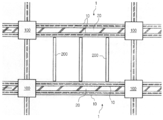
이하에서는 첨부한 도면을 참조하여 상기와 같은 본 발명의 철골-콘크리트 샌드위치 합성보를 이용하여 이루어진 구조 시스템에 관하여 설명한다. 도12와 도13은 본 발명의 합성 구조 시스템에 대한 평면 구성을 도시한 도면으로서 도12는 본 발명의 철골-콘크리트 샌드위치 합성보(1)를 일 방향(one-way)으로만 배치 설계한 구성을 도시한 것이고 도13은 이 방향(two-way)로 배치 설계한 평면 구성을 보이고 있다. 한편, 상기 도면들에 있어 미설명 부호 200은 통상의 빔 부재를 표시한 것이다. Hereinafter, with reference to the accompanying drawings will be described a structural system made using the steel-concrete sandwich composite beam of the present invention as described above. 12 and 13 illustrate a planar configuration of the composite structural system of the present invention. FIG. 12 illustrates a configuration in which the steel-concrete
상기 도면들에 도시된 바와 같이 본 발명의 철골-콘크리트 샌드위치 합성보를 사용한 고강성 구조 시스템은 기본적으로 기초 또는 슬래브 상부에 입설된 다수개의 기둥(100); 및, 상기 기둥(100)들 사이에 걸쳐 수평으로 설치되는 거더 부재로서, 보의 길이방향을 따라 서로 일정 간격을 두고 나란하게 병렬 배치된 한 쌍의 측면형강부재(10)와 상기 한 쌍의 측면형강부재(10)의 사이 공간에 타설, 양생된 충전콘크리트(20)를 포함하는 다수개의 철골-콘크리트 샌드위치 합성보(1);를 포함하여 이루어진다. As shown in the drawings, a highly rigid structural system using the steel-concrete sandwich composite beam of the present invention basically includes a plurality of
이와 같이 구성된 본 발명의 철골-콘크리트 샌드위치 합성보는 기존에 널리 사용되고 있던 RC(혹은 PC), 철골 또는 SRC와 같은 일반적 기둥 구공법은 물론, 최근 그 적용예가 증가하고 있는 CFT 기둥 공법 등 현재 사용되고 있는 어떠한 형식의 기둥 시스템과도 조합이 가능하며, 이에 따라 다양한 구조 프레임 방식의 형성이 가능하다. (각각의 공법에 대한 구체적 적용예는 이후에 상세히 설명한다.)The steel-concrete sandwich composite beam of the present invention configured as described above is widely used in general, such as RC (or PC), steel, or SRC, which is currently being widely used, as well as CFT pillar method, which is recently increasing in application. It can also be combined with a pillar system of the type, thereby forming a variety of structural framing methods. (Specific application examples for each method will be described later in detail.)
또한, 본 발명의 철골-콘크리트 샌드위치 합성보를 철골 구조 또는 SRC 구조에 적용하는 경우, 최초 세우기 공정(erection) 시 철골 부재만을 설치하여 골조를 형성할 수 있어 타워 크레인을 이용한 양중 시공이 가능하고 내부 충전콘크리트 콘 크리트의 타설 이전에 프레임 전체를 형성므로 시공의 능률성이 높아 공기 단축이 가능하다는 장점이 있다. In addition, when the steel-concrete sandwich composite beam of the present invention is applied to a steel structure or SRC structure, it is possible to form a frame by installing only a steel member during the initial erection (erection), it is possible to lift the construction using a tower crane and internal filling Since the entire frame is formed before concrete concrete is placed, there is an advantage of shortening the air due to high efficiency of construction.
나아가, 상기와 같은 본 발명의 철골-콘크리트 샌드위치 합성보를 사용한 고강성 구조 시스템은 구조적인 측면에서 응력 및 강도에 대해서는 철골 부재인 측면형강부재가 대부분 부담하되 내부에 타설, 양생된 충전콘크리트의 합성 작용에 의해 보 전체의 강성이 높아지는 효과와 감쇄 성능이 높아지는 효과가 있어 사용성 문제에 대한 효과적인 대응이 가능하다는 장점을 가지게 된다. In addition, the high rigid structural system using the steel-concrete sandwich composite beam of the present invention as described above, but the structural action of the cast concrete, which is placed and cured in the inner side of the structural member is mostly burdened by the steel member for the stress and strength This has the advantage of increasing the rigidity of the entire beam and the effect of increasing the attenuation performance has the advantage that an effective response to the usability problems can be.
이상과 같은 본 발명의 철골-콘크리트 샌드위치 합성보를 사용한 고강성 구조 시스템은 기존에 알려져 있던 다양한 기둥 형식과 조합 형성될 수 있으며, 이하에서는 각 기둥 구조 형식별로 본 발명의 철골-콘크리트 샌드위치 합성보를 적용하여 이루어진 구체적인 실시예들을 제시하고 이를 첨부한 도면과 함께 설명한다. High-strength structural system using the steel-concrete sandwich composite beam of the present invention as described above can be formed in combination with a variety of column types known in the art, hereinafter, by applying the steel-concrete sandwich composite beam of the present invention for each column structure type Detailed embodiments are made and described with reference to the accompanying drawings.
(1) CFT(Concrete Filled Tube) 기둥과의 접합부 상세(1) Details of the joint with the CFT (Concrete Filled Tube) column
도14는 본 발명의 철골-콘크리트 샌드위치 합성보와 CFT 기둥이 접합되는 접합부 디테일을 도시한 도면으로서, 상기 도면에 도시된 바와 같이 CFT 형식의 기둥(110)에 본 발명의 철골-콘크리트 샌드위치 합성보(1)를 접합 설치함에 있어서는 상기 CFT 기둥(110)의 소정 높이에 설치된 다이어프램(112)의 측단부에 본 발명의 합성보(1)를 접합하여 설치할 수 있다. 이 때, 상기 합성보(1)와 다이어프램(112) 의 접합은 용접 방식이 바람직하게 적용될 수 있을 것이다. 14 is a view showing the joint detail in which the steel-concrete sandwich composite beam of the present invention and the CFT column are joined, and the steel-concrete sandwich composite beam of the present invention (1) in the
(2) RC(또는 PC) 기둥과의 접합 상세(2) Joining details with RC (or PC) columns
도15는 본 발명의 철골-콘크리트 샌드위치 합성보와 철근콘크리트(RC) 기둥이 접합되는 접합부 디테일을 도시한 도면으로서, 상기 도면에 도시된 바와 같이 본 발명의 철골-콘크리트 샌드위치 합성보(1)를 통상의 RC 기둥(120)과 접합함에 있어서는 상기 합성보(1)의 측면형강부재(10)가 상기 RC기둥(120)을 수평으로 관통하도록 하여 설치하는 것이 적당하다. 이 때, 상기와 같은 구조를 시공함에 있어서는 기 시공된 RC기둥(120)의 상부에 측면형강부재(10)를 수평으로 지나가도록 설치한 상태에서 슬래브 콘크리트와 충전콘크리트(20)를 타설하여 시공하거나, 또는 하부층 슬래브 상에 기둥 거푸집을 설치하고 그 위에 측면형강부재(10)를 가설한 상태에서 슬래브 콘크리트, 충전콘크리트(20) 및 기둥 콘크리트(121)를 동시에 타설하여 시공하는 것도 가능하다. 15 is a view showing the joint detail in which the steel-concrete sandwich composite beam of the present invention and the reinforced concrete (RC) column are joined, and as shown in the drawing, the steel-concrete
(3) SRC 기둥과의 접합 상세 (3) Joining details with SRC pillar
도16은 SRC 기둥에 본 발명의 철골-콘크리트 샌드위치 합성보가 1방향으로 접합되는 접합부 디테일을 도시한 도면으로서, 상기 도면에 도시된 바와 같이 기둥 철골(133) 내에 철근 콘크리트를 타설하여 이루어진 SRC 기둥에 본 발명의 합성보 (1)를 접합하기 위해서는 상기와 같이 콘크리트(132) 내에 매설되는 기둥 철골(133)을 쌍을 이루어 배치하고 이들 기둥 철골(133)에 본 발명의 철골-콘크리트 샌드위치 합성보(1)의 측면형강부재(10)를 각각 접합 설치한다. 이 때, 상기 측면형강부재(10)는 상기 기둥 철골(133)의 강축 방향으로 접합되도록 구성한다.FIG. 16 is a view showing the joint detail in which the steel-concrete sandwich composite beam of the present invention is bonded in one direction to an SRC column, and as shown in the drawing, an SRC column formed by reinforcing concrete in a
도17은 상기와 같은 SRC 기둥(130)과 본 발명에 따른 합성보(1)의 접합에 있어 본 발명의 합성보(1)가 2방향(two-way)으로 접합되는 접합부 디테일을 도시한 도면으로, 이와 같은 시스템에 있어서는 도16에서와 같이 H-형강 기둥 철골(133)을 2본으로 형성하되 상기 한 쌍의 H-형강 기둥철골(133) 사이에는 평판형의 스틸 플레이트를 수평으로 접합하여 다이어프램(135)를 설치하고 이 다이어프램(135)의 측단부에 본 발명의 철골-콘크리트 샌드위치 합성보(1)를 용접 등의 방법을 이용하여 접합 설치한다. FIG. 17 is a view showing joint details in which the
(4) 철골 기둥과의 접합 상세 (4) Joining details with steel column
도18과 도19는 본 발명의 철골-콘크리트 샌드위치 합성보를 철골 기둥에 적용한 예들을 도시한 도면으로서, 도18은 본 발명의 합성보(1)를 철골 기둥(140)과 일방향으로 접합한 예를, 도19는 2방향으로 접합한 예를 도시하고 있다. 도시된 바와 같이 본 발명의 철골-콘크리트 샌드위치 합성보(1)를 철골 기둥(140)에 접합함에 있어서는 기둥 철골(140)를 합성보(1)를 이루는 측면형강부재(10)와 같이 한 쌍으로 형성하고, 이 기둥 철골(14)의 각각에 측면형강부재(10)의 단부를 접합하는 것이 바람직하다. 18 and 19 are views showing examples in which the steel-concrete sandwich composite beam of the present invention is applied to a steel column, and FIG. 18 shows an example in which the
한편, 상기와 같이 기둥 철골(140)을 2본으로 형성하게 되면, 도17, 도18의 도시에서 알 수 있는 바와 같이 기둥 철골(140)의 플랜지 길이에 비해 웨브의 길이가 통상의 기둥 철골에 비해 훨씬 길어짐으로써 기둥의 세장비(細長比)가 커지게 되어 좌굴 등의 위험이 있게 되는 바 이에 대한 적절한 조치를 필요로 하게 된다. 도18, 19에 있어 미설명 식별부호 145는 상기와 같은 문제점의 해결을 위해 설치된 사이드 플레이트를 도시한 것으로, 상기 사이드 플레이트(145)는 상기 한 쌍의 기둥 철골(140)들을 상호 결속하게 설치됨으로써 기둥의 좌굴 길이를 감소시키고 강성을 증대시키는 역할을 한다. On the other hand, when the
본 발명은 상기한 바와 같이 기존에 알려진 RC 구조, PC 구조를 비롯하여 SRC 구조와 같은 합성 구조 시스템이 갖는 문제점을 개선하기 위하여 안출된 것으로서, 더욱 구체적으로 본 발명은 보의 양측으로 쌍을 이루어 배치된 철골 형강 부재가 거푸집의 역할을 함으로써 거푸집 설치, 해체 공사를 전혀 필요로 하지 않아 시공의 편의성 및 공사비 절감 효과가 뛰어나며, 구조적인 면에서도 보 양측의 철골 부재들과 이들 사이에 충전 타설된 콘크리트의 합성 작용에 의하여 동일한 강성을 갖는 기존 RC 및 PC보에 비하여 단면 크기를 상당히 줄일 수 있는 효과를 얻을 수 있다.The present invention has been made to improve the problems of the conventional structural structure system, such as the RC structure, PC structure, SRC structure, as described above, more specifically the present invention is arranged in pairs on both sides of the beam Since the steel frame member acts as a formwork, it does not require any form installation and dismantling work, so it is easy to construct and reduce construction cost. By the action, it is possible to obtain an effect of significantly reducing the cross-sectional size compared to the existing RC and PC beams having the same rigidity.
Claims (22)
Priority Applications (2)
| Application Number | Priority Date | Filing Date | Title |
|---|---|---|---|
| KR1020040073688A KR20060024850A (en) | 2004-09-15 | 2004-09-15 | Steel-concrete sandwitch type hybrid beam and high strength hybrid structure system using the same |
| PCT/KR2004/003206 WO2006031001A1 (en) | 2004-09-15 | 2004-12-08 | Steel-concrete sandwitch type hybrid beam and high strengh hybrid structure system using the same |
Applications Claiming Priority (1)
| Application Number | Priority Date | Filing Date | Title |
|---|---|---|---|
| KR1020040073688A KR20060024850A (en) | 2004-09-15 | 2004-09-15 | Steel-concrete sandwitch type hybrid beam and high strength hybrid structure system using the same |
Publications (1)
| Publication Number | Publication Date |
|---|---|
| KR20060024850A true KR20060024850A (en) | 2006-03-20 |
Family
ID=36060229
Family Applications (1)
| Application Number | Title | Priority Date | Filing Date |
|---|---|---|---|
| KR1020040073688A KR20060024850A (en) | 2004-09-15 | 2004-09-15 | Steel-concrete sandwitch type hybrid beam and high strength hybrid structure system using the same |
Country Status (2)
| Country | Link |
|---|---|
| KR (1) | KR20060024850A (en) |
| WO (1) | WO2006031001A1 (en) |
Cited By (12)
| Publication number | Priority date | Publication date | Assignee | Title |
|---|---|---|---|---|
| KR100802515B1 (en) * | 2006-10-17 | 2008-02-12 | 한국건설기술연구원 | Composite floor structure using two precast composite steel beams |
| KR101320571B1 (en) * | 2011-03-16 | 2013-10-28 | 재단법인 포항산업과학연구원 | Steel composite girder module and method of constructing the same |
| CN106284840A (en) * | 2016-09-22 | 2017-01-04 | 广东省建筑设计研究院 | A kind of second pouring steel reinforced concrete frame beam and construction method thereof |
| KR20170139873A (en) * | 2016-06-10 | 2017-12-20 | 주식회사 하이브릭스이앤씨 | Coupling structure of double type for girder and column capable of reducing girder height |
| CN107965090A (en) * | 2017-12-29 | 2018-04-27 | 广东象博生态科技有限公司 | A kind of pillar construction and assembled-type house for assembled-type house |
| KR20190044763A (en) * | 2017-10-23 | 2019-05-02 | 심남주 | Unidirectional structure of wide double composite girder in which steel members is placed in the lower section thereof |
| KR102183966B1 (en) * | 2020-03-04 | 2020-11-27 | (주)쓰리디엔지니어링 | Combination structure system of composite columns using two H beams and composite beams using two H beams |
| KR102277253B1 (en) * | 2020-11-26 | 2021-07-13 | 코오롱이앤씨 주식회사 | Rapid construction process Rahmen structure system and construction methods for utilizing the CTS slab |
| CN114411975A (en) * | 2022-02-13 | 2022-04-29 | 重庆交通大学 | Composite bolt shear key structure |
| KR20220124348A (en) * | 2021-03-03 | 2022-09-14 | 코오롱이앤씨 주식회사 | Rapid construction method using unit member |
| KR102495902B1 (en) * | 2022-02-08 | 2023-02-06 | (주)아이에스산업 | Joint structure of cft steel pipe column and charging bracket |
| KR20230090300A (en) | 2015-11-02 | 2023-06-21 | 주식회사 태영피씨엠 | A twin wall structure using a PC panel and method for manufacturing of it |
Families Citing this family (12)
| Publication number | Priority date | Publication date | Assignee | Title |
|---|---|---|---|---|
| FR2925088B1 (en) * | 2007-12-18 | 2014-12-26 | Soc Civ D Brevets Matiere | METHOD FOR PRODUCING AN ARMED CONCRETE BUILDING ELEMENT AND CONSTRUCTION ELEMENT THUS PRODUCED |
| ITUD20120188A1 (en) * | 2012-11-09 | 2014-05-10 | Giuseppe Suraci | STRUCTURAL ELEMENT FOR BUILDING CONSTRUCTION, BUILDING CONSTRUCTION BUYING UPON THE STRUCTURAL ELEMENT, AND PROCEDURE FOR THE CONSTRUCTION OF SUCH A STRUCTURAL ELEMENT |
| CN104060761B (en) * | 2014-05-23 | 2016-03-09 | 浙江东南网架股份有限公司 | U-shaped steel concrete combination beam and construction method thereof |
| CN104563391B (en) * | 2014-10-31 | 2016-08-24 | 华南理工大学 | The regenerative mixed beam of the discontinuous I-steel in a kind of built-in top flange and construction technology thereof |
| JP2016089549A (en) * | 2014-11-10 | 2016-05-23 | 株式会社大林組 | Structure and method for joining reinforced concrete beam and steel column or column comprising steel column |
| CN105155774B (en) * | 2015-08-10 | 2017-09-19 | 河海大学 | Double-deck channel-section steel regeneration concrete combination beam |
| CN105672568B (en) * | 2016-03-29 | 2018-01-16 | 济南长兴建设集团有限公司 | Super-section strengthening concrete conversion beam placement layer by layer construction method |
| CN108775084B (en) * | 2018-07-09 | 2023-06-09 | 东南大学 | Steel-concrete combined precast beam and precast column connecting structure and construction method |
| CN108589931A (en) * | 2018-07-25 | 2018-09-28 | 浙江大学 | The precast construction connecting node that concrete is combined with steel construction |
| JP7265343B2 (en) * | 2018-11-09 | 2023-04-26 | 株式会社竹中工務店 | steel building |
| FR3093743B1 (en) * | 2019-03-12 | 2022-01-21 | Plattard Sas | Draft of a pre-formed concrete beam comprising a bottom and side panels |
| CN110453584A (en) * | 2019-07-11 | 2019-11-15 | 安徽省交通控股集团有限公司 | A kind of Steel-concrete Combined Beam Structures using weather-proof Wavelike steel webplate |
Family Cites Families (6)
| Publication number | Priority date | Publication date | Assignee | Title |
|---|---|---|---|---|
| JPS525856Y2 (en) * | 1973-11-26 | 1977-02-07 | ||
| JPS6165116U (en) * | 1984-10-04 | 1986-05-02 | ||
| JPS61165452A (en) * | 1985-01-16 | 1986-07-26 | 株式会社竹中工務店 | Concrete filled steel beam |
| JPH0768741B2 (en) * | 1991-02-05 | 1995-07-26 | 鹿島建設株式会社 | Steel concrete beam |
| KR100374537B1 (en) * | 1999-09-28 | 2003-03-03 | 삼성물산 주식회사 | Joint of reinforced concrete column and steel beam |
| AU754130B1 (en) * | 2001-06-05 | 2002-11-07 | Bonacci Beam Pty Ltd | Building structural element |
-
2004
- 2004-09-15 KR KR1020040073688A patent/KR20060024850A/en not_active Application Discontinuation
- 2004-12-08 WO PCT/KR2004/003206 patent/WO2006031001A1/en active Application Filing
Cited By (16)
| Publication number | Priority date | Publication date | Assignee | Title |
|---|---|---|---|---|
| KR100802515B1 (en) * | 2006-10-17 | 2008-02-12 | 한국건설기술연구원 | Composite floor structure using two precast composite steel beams |
| KR101320571B1 (en) * | 2011-03-16 | 2013-10-28 | 재단법인 포항산업과학연구원 | Steel composite girder module and method of constructing the same |
| KR20230090300A (en) | 2015-11-02 | 2023-06-21 | 주식회사 태영피씨엠 | A twin wall structure using a PC panel and method for manufacturing of it |
| KR20170139873A (en) * | 2016-06-10 | 2017-12-20 | 주식회사 하이브릭스이앤씨 | Coupling structure of double type for girder and column capable of reducing girder height |
| KR101878762B1 (en) * | 2016-06-10 | 2018-07-16 | 주식회사 하이브릭스이앤씨 | Coupling structure of double type for girder and column capable of reducing girder height |
| CN106284840A (en) * | 2016-09-22 | 2017-01-04 | 广东省建筑设计研究院 | A kind of second pouring steel reinforced concrete frame beam and construction method thereof |
| CN106284840B (en) * | 2016-09-22 | 2017-10-24 | 广东省建筑设计研究院 | A kind of second pouring steel reinforced concrete frame beam and its construction method |
| KR20190044763A (en) * | 2017-10-23 | 2019-05-02 | 심남주 | Unidirectional structure of wide double composite girder in which steel members is placed in the lower section thereof |
| CN107965090A (en) * | 2017-12-29 | 2018-04-27 | 广东象博生态科技有限公司 | A kind of pillar construction and assembled-type house for assembled-type house |
| CN107965090B (en) * | 2017-12-29 | 2023-07-07 | 广东象博生态科技有限公司 | Upright post structure for assembled house and assembled house |
| KR102183966B1 (en) * | 2020-03-04 | 2020-11-27 | (주)쓰리디엔지니어링 | Combination structure system of composite columns using two H beams and composite beams using two H beams |
| KR102277253B1 (en) * | 2020-11-26 | 2021-07-13 | 코오롱이앤씨 주식회사 | Rapid construction process Rahmen structure system and construction methods for utilizing the CTS slab |
| KR20220124348A (en) * | 2021-03-03 | 2022-09-14 | 코오롱이앤씨 주식회사 | Rapid construction method using unit member |
| KR102495902B1 (en) * | 2022-02-08 | 2023-02-06 | (주)아이에스산업 | Joint structure of cft steel pipe column and charging bracket |
| CN114411975A (en) * | 2022-02-13 | 2022-04-29 | 重庆交通大学 | Composite bolt shear key structure |
| CN114411975B (en) * | 2022-02-13 | 2023-11-07 | 重庆交通大学 | Structure of composite bolting shear key |
Also Published As
| Publication number | Publication date |
|---|---|
| WO2006031001A1 (en) | 2006-03-23 |
Similar Documents
| Publication | Publication Date | Title |
|---|---|---|
| KR20060024850A (en) | Steel-concrete sandwitch type hybrid beam and high strength hybrid structure system using the same | |
| KR100797194B1 (en) | Composite concrete column and construction method using the same | |
| CN109469202A (en) | Prestressed assembly integral concrete frame structure system and construction method thereof | |
| KR101464866B1 (en) | Composite beam having tie anchor embedded in a concrete | |
| KR102079008B1 (en) | E-z connecting structure for beam and column wherein the end-moment and bending resistibility are reinforced | |
| KR100447013B1 (en) | Beam system composed of asymmetric steel section with web hole and concrete | |
| JP2006328631A (en) | Building floor structure system | |
| CN105822000A (en) | Steel plate and concrete composite beam and slab structure system | |
| KR20180069554A (en) | Prestressed steel circular tube girder with partial filled concrete and structure construction method by using it | |
| KR101045929B1 (en) | Pro-environment prestressed long span light-weight precast concrete panel and this construction technique | |
| KR100626544B1 (en) | Hybrid Beam of Steel Plate and Concrete, and High Streng Hybrid Structure System Using The Same | |
| KR20110003884A (en) | Heterogeneity reinforcing composite profile beam | |
| CN113006576A (en) | Assembled prestressed steel-concrete combined frame system and construction method thereof | |
| KR100727114B1 (en) | Precast segment for constructing through bridges and the constructing method using it | |
| KR100949828B1 (en) | Steel beam and hybrid beam of steel concrete for slim floor | |
| KR100939970B1 (en) | A method of constructing a complex girder and its structure | |
| KR100343960B1 (en) | Steel concrete structure | |
| KR101006975B1 (en) | Slim floor system by continuous two-way hollow core slab | |
| KR101521946B1 (en) | Enlarged capital of steel framed reinforced concrete column | |
| KR20130117204A (en) | Earthquake-resistant frame and seismic retrofit method for building using the same | |
| CN215053877U (en) | Assembled prestressed concrete frame system | |
| KR100578641B1 (en) | Steel-Concrete Hybrid Column, Hybrid Structure System Using the Same, and Construction Method Thereof | |
| KR20170139873A (en) | Coupling structure of double type for girder and column capable of reducing girder height | |
| KR20020060429A (en) | Joint of reinforced concrete column and steel beam and a method of the same | |
| KR20070053836A (en) | Apparatus for enhancing shear strength of colum slab connecton part and its menufacturing method |
Legal Events
| Date | Code | Title | Description |
|---|---|---|---|
| A201 | Request for examination | ||
| E902 | Notification of reason for refusal | ||
| E601 | Decision to refuse application |