KR200496715Y1 - Spacer to separate corrugated pipes - Google Patents
Spacer to separate corrugated pipes Download PDFInfo
- Publication number
- KR200496715Y1 KR200496715Y1 KR2020210002802U KR20210002802U KR200496715Y1 KR 200496715 Y1 KR200496715 Y1 KR 200496715Y1 KR 2020210002802 U KR2020210002802 U KR 2020210002802U KR 20210002802 U KR20210002802 U KR 20210002802U KR 200496715 Y1 KR200496715 Y1 KR 200496715Y1
- Authority
- KR
- South Korea
- Prior art keywords
- corrugated
- corrugated pipe
- spacer
- tubes
- ground
- Prior art date
Links
Images


Classifications
-
- F—MECHANICAL ENGINEERING; LIGHTING; HEATING; WEAPONS; BLASTING
- F16—ENGINEERING ELEMENTS AND UNITS; GENERAL MEASURES FOR PRODUCING AND MAINTAINING EFFECTIVE FUNCTIONING OF MACHINES OR INSTALLATIONS; THERMAL INSULATION IN GENERAL
- F16L—PIPES; JOINTS OR FITTINGS FOR PIPES; SUPPORTS FOR PIPES, CABLES OR PROTECTIVE TUBING; MEANS FOR THERMAL INSULATION IN GENERAL
- F16L1/00—Laying or reclaiming pipes; Repairing or joining pipes on or under water
- F16L1/024—Laying or reclaiming pipes on land, e.g. above the ground
- F16L1/06—Accessories therefor, e.g. anchors
-
- F—MECHANICAL ENGINEERING; LIGHTING; HEATING; WEAPONS; BLASTING
- F16—ENGINEERING ELEMENTS AND UNITS; GENERAL MEASURES FOR PRODUCING AND MAINTAINING EFFECTIVE FUNCTIONING OF MACHINES OR INSTALLATIONS; THERMAL INSULATION IN GENERAL
- F16L—PIPES; JOINTS OR FITTINGS FOR PIPES; SUPPORTS FOR PIPES, CABLES OR PROTECTIVE TUBING; MEANS FOR THERMAL INSULATION IN GENERAL
- F16L3/00—Supports for pipes, cables or protective tubing, e.g. hangers, holders, clamps, cleats, clips, brackets
- F16L3/22—Supports for pipes, cables or protective tubing, e.g. hangers, holders, clamps, cleats, clips, brackets specially adapted for supporting a number of parallel pipes at intervals
-
- F—MECHANICAL ENGINEERING; LIGHTING; HEATING; WEAPONS; BLASTING
- F16—ENGINEERING ELEMENTS AND UNITS; GENERAL MEASURES FOR PRODUCING AND MAINTAINING EFFECTIVE FUNCTIONING OF MACHINES OR INSTALLATIONS; THERMAL INSULATION IN GENERAL
- F16L—PIPES; JOINTS OR FITTINGS FOR PIPES; SUPPORTS FOR PIPES, CABLES OR PROTECTIVE TUBING; MEANS FOR THERMAL INSULATION IN GENERAL
- F16L7/00—Supporting of pipes or cables inside other pipes or sleeves, e.g. for enabling pipes or cables to be inserted or withdrawn from under roads or railways without interruption of traffic
- F16L7/02—Supporting of pipes or cables inside other pipes or sleeves, e.g. for enabling pipes or cables to be inserted or withdrawn from under roads or railways without interruption of traffic and sealing the pipes or cables inside the other pipes, cables or sleeves
-
- F—MECHANICAL ENGINEERING; LIGHTING; HEATING; WEAPONS; BLASTING
- F16—ENGINEERING ELEMENTS AND UNITS; GENERAL MEASURES FOR PRODUCING AND MAINTAINING EFFECTIVE FUNCTIONING OF MACHINES OR INSTALLATIONS; THERMAL INSULATION IN GENERAL
- F16L—PIPES; JOINTS OR FITTINGS FOR PIPES; SUPPORTS FOR PIPES, CABLES OR PROTECTIVE TUBING; MEANS FOR THERMAL INSULATION IN GENERAL
- F16L9/00—Rigid pipes
- F16L9/02—Rigid pipes of metal
- F16L9/06—Corrugated pipes
-
- Y—GENERAL TAGGING OF NEW TECHNOLOGICAL DEVELOPMENTS; GENERAL TAGGING OF CROSS-SECTIONAL TECHNOLOGIES SPANNING OVER SEVERAL SECTIONS OF THE IPC; TECHNICAL SUBJECTS COVERED BY FORMER USPC CROSS-REFERENCE ART COLLECTIONS [XRACs] AND DIGESTS
- Y02—TECHNOLOGIES OR APPLICATIONS FOR MITIGATION OR ADAPTATION AGAINST CLIMATE CHANGE
- Y02E—REDUCTION OF GREENHOUSE GAS [GHG] EMISSIONS, RELATED TO ENERGY GENERATION, TRANSMISSION OR DISTRIBUTION
- Y02E10/00—Energy generation through renewable energy sources
- Y02E10/10—Geothermal energy
Abstract
이 고안의 파형관 이격 스페이서(200)는 파형관(300) 간의 좌우 이격거리를 유지하는 폭과 상하 파형관(300) 간의 상하 되메우기의 기준선을 제시하는 길이를 갖는 중공형의 몸체(210)와, 지중에 원활하게 박히도록 몸체(210)의 하단에서 하부방향으로 뾰족하게 돌출되는 돌출부(220)와, 지면과의 접촉면적을 증대시키도록 몸체(210)의 하단과 돌출부(220)의 사이에 위치하는 지지부(230)와, 몸체(210)의 상단에 끼워져 고정되는 하부 구조와 몸체(210)와 동일한 폭과 길이를 갖는 중공형의 연장 몸체(240), 및 몸체(210) 또는 연장 몸체(240)의 상단에 끼워지는 마감 덮개(250)를 포함하여 구성된다. The corrugated tube spacing spacer 200 of this design has a hollow body 210 having a width that maintains the left-right separation distance between the corrugated tubes 300 and a length that presents a reference line of vertical backfill between the upper and lower corrugated tubes 300, and A protrusion 220 sharply protrudes downward from the lower end of the body 210 so as to be smoothly inserted, and a support positioned between the lower end of the body 210 and the protrusion 220 to increase the contact area with the ground 230, a lower structure inserted and fixed to the top of the body 210, a hollow extension body 240 having the same width and length as the body 210, and the body 210 or the extension body 240 It is configured to include a closing cover 250 fitted at the top.
Description
이 고안은 파형관 이격 스페이서에 관한 것으로서, 더욱 상세하게는 근접 파형관의 측면에 각각 밀착되어 좌우 파형관 간의 좌우 이격거리를 유지함과 더불어 상하 파형관 간의 상하 되메우기의 기준선을 제시하고, 파형관의 내부에서 발생하는 열을 외부로 빠르게 발산할 수 있는 통로를 제공하는 파형관 이격 스페이서에 관한 것이다. This invention relates to a corrugated tube spacing spacer, and more specifically, adheres to the side surfaces of adjacent corrugated tubes to maintain the left-right separation distance between the left and right corrugated tubes, presents a baseline for vertical backfilling between the upper and lower corrugated tubes, and heat generated inside the corrugated tubes. It relates to a corrugated pipe spacing spacer that provides a passage through which a can quickly dissipate to the outside.
지중에 케이블을 매설함에 있어서, 땅을 파고 케이블을 별도의 보조장치 없이 그대로 매설할 경우, 케이블이 엉킬 수 있고 또한 케이블이 어떤 케이블인지를 분간하기도 어려울 뿐만 아니라 케이블이 그대로 노출됨에 따라 공사시에 포크레인 등에 의해 손상될 우려가 있다. 그래서, 파형관을 지하에 매립하고, 이 파형관의 내부에 케이블을 포설하고 있다.In burying cables in the ground, if the ground is dug and the cable is buried as it is without a separate auxiliary device, the cable may get tangled and it is difficult to distinguish which cable it is, and as the cable is exposed as it is, There is a risk of being damaged by, etc. Therefore, the corrugated pipe is buried underground, and cables are installed inside the corrugated pipe.
한편, 파형관을 지하에 매립함에 있어서는 다수개의 파형관을 좌우방향 및 상하방향으로 매립하는 바, 파형관 간의 간격 유지를 위해 간격 유지용 합판을 이용하고 있는데 파형관의 매립후에는 간격 유지용 합판을 제거하고 있다. 즉, 파형관을 별도로 지지하거나 고정하지 않음에 따라, 시간의 경과에 따라 파형관 간의 일정한 관로 유지가 어렵고, 침하나 유동으로 인해 좌우 파형관 간의 간격 유지에 어려움이 있다. 이는 파형관의 꺾임 현상을 초래하고, 그로 인해 파형관의 내부에 케이블을 포설할 수가 없어 파형관을 재시공해야 하는 문제점과, 파형관의 재시공을 위해 이미 포설된 파형관 내부의 케이블을 분리하는 작업을 수행함에 있어서, 파형관의 꺾임 부위로 인해 케이블이 잘 빠지지 않는 문제점이 있다.On the other hand, when corrugated tubes are buried underground, a plurality of corrugated tubes are buried in the left-right and vertical directions, and plywood for maintaining spacing is used to maintain the spacing between the corrugated tubes. After the corrugated tubes are buried, the plywood for maintaining the spacing is removed. . That is, since the corrugated tubes are not separately supported or fixed, it is difficult to maintain a constant pipe path between the corrugated tubes over time, and it is difficult to maintain the distance between the left and right corrugated tubes due to settlement or flow. This causes the bending of the corrugated pipe, which causes the problem of re-construction of the corrugated pipe because the cable cannot be laid inside the corrugated pipe, and the work of separating the cable inside the corrugated pipe already installed for re-construction of the corrugated pipe In performing the work, There is a problem in that the cable does not come out well due to the bent portion of the corrugated pipe.
한편, 파형관의 매립시에 상기와 같은 간격 유지용 합판 이외에도 스페이서를 이용하고 있다. 실용신안등록 제20-0194962호에는 "파형관용 스페이서"에 대해 공개되어 있다. 도 1은 실용신안등록 제20-0194962호의 파형관용 스페이서의 사시도이고, 도 2는 도 1에 도시된 파형관용 스페이서의 상부에 다른 파형관용 스페이서를 적층시킨 상태의 상세도이다.On the other hand, when the corrugated pipe is embedded, a spacer is used in addition to the plywood for maintaining the distance as described above. Utility model registration No. 20-0194962 discloses a "spacer for corrugated pipe". 1 is a perspective view of a corrugated pipe spacer of Utility Model Registration No. 20-0194962, and FIG. 2 is a detailed view of a state in which another corrugated pipe spacer is stacked on top of the corrugated pipe spacer shown in FIG.
도 1 및 도 2에 도시된 바와 같이, 종래의 파형관용 스페이서(10)는 그 상부에 반원형 홈부(1)가 다수개 형성되고 하부에도 반원형 홈부(4)가 다수개 형성되는데, 이들 반원형 홈부(1, 4)가 서로 간에 대칭되게 형성된다. 그리고, 상기 반원형 홈부(1)사이의 상면에는 각각 삽입돌기(2)가 형성되고, 상기 반원형 홈부(4)사이의 하면에는 각각 삽입홈(3)이 형성된다.As shown in FIGS. 1 and 2, the conventional
따라서, 이와 같은 파형관용 스페이서(10)의 반원형 홈부(1)내에 파형관을 각각 위치시킬 수 있으며, 또한 이 파형관용 스페이서(10)의 상부에 도 2에 도시된 바와 같이 다른 파형관용 스페이서(20)를 계속적으로 결합시켜 사용할 수가 있다.Accordingly, the corrugated tubes can be positioned within the
즉, 상기 파형관용 스페이서(10)의 상하부에 형성된 삽입돌기(2)와 삽입홈(3)을 이용하여 삽입돌기(2)를 다른 파형관용 스페이서(10)의 삽입홈(3)에 삽입시킴으로써 파형관용 스페이서(20)를 적층하여 결합시킬 수가 있다. 이와 같이 적층된 파형관용 스페이서(10, 20)의 홈부(1, 4)에 파형관을 끼워 고정하고, 이 파형관의 내부에 다수의 케이블을 질서정연하게 배치할 수가 있다.That is, by inserting the
그런데, 도 1 및 도 2와 같은 종래의 파형관용 스페이서(10)는 홈부(1, 4)가 파형관의 설치방향으로 직선형태의 표면, 즉 파형관의 외주면과 접촉하는 표면이 직선형태를 가짐에 따라, 스페이서(10)의 외측에 위치하는 파형관에 가해지는 외력(흙의 무게, 충격 등)에 의해 파형관이 꺾이는 현상이 발생한다. 이러한 파형관의 꺾임 현상이 발생하면, 파형관의 내부에 전선을 포설할 수가 없어 파형관을 재시공해야만 한다. 그런데, 파형관의 재시공을 위해 이미 포설된 파형관 내부의 전선을 분리하는 작업을 수행함에 있어서, 파형관의 꺾임 부위로 인해 케이블이 잘 빠지지 않는 문제점이 있다. However, in the
또한, 종래의 파형관용 스페이서(10)는 파형관을 고정하는 홈부(1, 4)의 테두리가 폐쇄된 형태, 즉 개방홈이나 구멍 등의 통로를 별도로 구비하지 않음에 따라, 파형관 내부의 케이블에서 발생하는 열을 지중 등으로 빠르게 발산할 수 없는 문제점이 있다.In addition, the
한편, 실용신안등록 제20-0429651호에는 "파형관 고정용 스페이서"에 대해 공개되어 있다. 도 3은 실용신안등록 제20-0429651호의 파형관 고정용 스페이서를 개략적으로 도시한 사시도이고, 도 4는 도 3에 도시된 파형관 고정용 스페이서를 다수개 조립하여 사용하는 상태의 상세도이다.Meanwhile, Utility Model Registration No. 20-0429651 discloses a "spacer for fixing a corrugated tube". 3 is a perspective view schematically showing a spacer for fixing a corrugated pipe of Utility Model Registration No. 20-0429651, and FIG. 4 is a detailed view of a state in which a plurality of spacers for fixing a corrugated pipe shown in FIG. 3 are assembled and used.
상기 실용신안등록 제20-0429651호는 1단 및 2단 스페이서를 용이하게 결합할 수 있고, 파형관의 포설 시공능률을 향상시킬 수 있으며, 간격을 장기간 유지할 수 있음과 동시에 시공 품질을 향상시킬 수 있도록 구성한 것이다. 이를 위해, 도 3 및 도 4에 도시된 바와 같이, 종래의 파형관 고정용 스페이서는 좌측 및 우측 벽체(112, 113)의 상부면 중앙에 형성된 제1 및 제2 상부 관통공(110, 111)과, 제1 및 제2 상부 관통공(110, 111)내에 삽입되도록 좌측 및 우측 벽체(112, 113)의 하부면 중앙에 돌출 형성된 제1 및 제2 결합핀(120, 121)을 갖도록 구성되어 있다. 도면의 미설명 부호 114는 상부 벽체, 115는 구획판, 116, 117는 보강 돌출판, 116a, 116b는 관통공, 118은 원형 돌기, 119는 사이드 원형 관통공, 125는 파형관, 130은 케이블을 각각 나타낸다. The Utility Model Registration No. 20-0429651 can easily combine the 1st and 2nd spacers, improve the installation efficiency of the corrugated pipe, maintain the interval for a long period of time, and improve the construction quality at the same time. it is composed To this end, as shown in FIGS. 3 and 4, the conventional spacer for fixing the corrugated pipe includes first and second upper through-
그런데, 도 3 및 도 4와 같은 종래의 파형관 고정용 스페이서는 파형관이 접촉하는 상부 벽체(114)의 표면이 평면형태를 가짐에 따라, 스페이서의 외측에 위치하는 파형관에 가해지는 외력(흙의 무게, 충격 등)에 의해 파형관이 꺾이는 현상이 발생하고, 그로 인해 상술한 바와 동일한 여러 문제점이 발생한다.By the way, in the conventional spacer for fixing the corrugated pipe as shown in FIGS. 3 and 4, as the surface of the
따라서, 이 고안은 앞서 설명한 바와 같은 종래기술의 문제점을 해결하기 위하여 개발된 것으로서, 근접 파형관의 측면에 각각 밀착되어 좌우 파형관 간의 좌우 이격거리를 유지함과 더불어 상하 파형관 간의 상하 되메우기의 기준선을 제시하고, 파형관의 내부에서 발생하는 열을 외부로 빠르게 분산 및 발산할 수 있는 통로를 제공하는 파형관 이격 스페이서를 제공하는데 그 목적이 있다.Therefore, this design was developed to solve the problems of the prior art as described above, and is closely adhered to the side surfaces of the adjacent corrugated tubes to maintain the left and right separation distance between the left and right corrugated tubes, as well as to present a baseline for vertical backfilling between the upper and lower corrugated tubes, An object of the present invention is to provide a corrugated pipe spacing spacer that provides a passage through which heat generated inside the corrugated pipe can be rapidly dispersed and dissipated to the outside.
상기와 같은 목적을 달성하기 위한 이 고안의 파형관 이격 스페이서는, 지중에 좌우방향으로 매립될 좌우 파형관의 측면에 각각 밀착되어 상기 좌우 파형관 간의 좌우 이격거리를 유지하는 폭과, 상하방향으로 매립될 상하 파형관 간의 상하 되메우기의 기준선을 제시하는 길이를 갖는 중공형의 몸체와; 지중에 원활하게 박히도록 상기 몸체의 하단에서 하부방향으로 뾰족하게 돌출되는 돌출부; 및 지면과의 접촉면적을 증대시키도록 상기 몸체의 하단과 상기 돌출부의 사이에 위치하되, 상기 몸체의 하단 둘레에 상기 몸체와 직교방향으로 외측으로 연장하여 형성되는 지지부를 포함하는 것을 특징으로 한다. The corrugated pipe spacing spacer of this design to achieve the above object is in close contact with the side surfaces of the left and right corrugated pipes to be buried in the left and right directions in the ground, and the width to maintain the left and right separation distance between the left and right corrugated pipes, and the top and bottom to be buried in the vertical direction a hollow body having a length presenting a reference line of upper and lower backfilling between the corrugated tubes; A protruding portion that protrudes sharply downward from the lower end of the body so as to be smoothly embedded in the ground; and a support portion positioned between the lower end of the body and the protrusion to increase a contact area with the ground, and extending outwardly around the lower end of the body in a direction orthogonal to the body.
또한, 이 고안에 따르면, 상기 몸체의 상단 내부에 끼워져 고정되는 하부 구조와 상기 몸체와 동일한 폭과 길이를 갖는 중공형의 연장 몸체를 1개 이상 더 포함할 수 있다. In addition, according to this design, one or more hollow extension bodies having the same width and length as the body and a lower structure fitted and fixed inside the upper end of the body may be further included.
또한, 이 고안에 따르면, 상기 몸체 또는 상기 연장 몸체의 상단 내부에 끼워지는 마감 덮개를 더 포함할 수 있다. In addition, according to this design, it may further include a closing cover fitted inside the upper end of the body or the extension body.
또한, 이 고안에 따르면, 상기 지지부는 하부방향으로 뾰족하게 돌출되는 다수개의 돌기를 더 구비하는 것이 바람직하다. In addition, according to this design, it is preferable that the support part further includes a plurality of projections protruding sharply downward.
또한, 이 고안에 따르면, 상기 몸체는 사각형 단면 형태를 가지며, 상기 몸체 중에서 상기 좌우 파형관과 밀착하는 표면에는 폭방향으로 다수개의 보강리브가 더 돌출 형성되는 것이 더 바람직하다.In addition, according to this design, the body has a rectangular cross-section, and it is more preferable that a plurality of reinforcing ribs are formed to protrude further in the width direction on the surface of the body in close contact with the left and right corrugated tubes.
또한, 이 고안에 따르면, 상기 지지부는 상기 좌우 파형관이 밀착하는 표면 쪽에만 형성되는 것이 더 바람직하다. Further, according to this design, it is more preferable that the support portion is formed only on the surface side where the left and right corrugated tubes come into close contact.
이 고안의 파형관 이격 스페이서는 근접 파형관의 측면에 각각 밀착되어 좌우 파형관 간의 좌우 이격거리를 유지함과 더불어, 상하 파형관 간의 상하 되메우기의 기준선 제시를 통해 상하 파형관 간에 항상 일정한 상하 이격거리로 파형관을 매립할 수 있도록 한다. 즉, 이 고안의 파형관 이격 스페이서는 파형관을 상하좌우 어느 방향으로도 구속하지 않으므로 지반 침하시에도 스페이서로 인해 파형관이 꺾일 염려가 전혀 없어 파형관의 재시공 작업을 줄이고 케이블을 파형관 내부로 편리하면서 원활하게 포설할 수 있을 뿐만 아니라, 파형관 간의 좌우 이격거리를 항상 유지할 수 있어서 파형관 간의 충돌 및 그로 인한 파손 등을 예방할 수가 있다. The corrugated pipe spacing spacer of this design is in close contact with the side surfaces of the adjacent corrugated pipes to maintain the left and right separation distance between the left and right corrugated pipes, and also to embed the corrugated pipes with a constant vertical separation distance between the upper and lower corrugated pipes by presenting the baseline for vertical backfill between the upper and lower corrugated pipes. let it be In other words, the corrugated pipe spacing spacer of this design does not restrict the corrugated pipe in any direction, so there is no fear of the corrugated pipe being bent due to the spacer even during ground subsidence, reducing the work of reconstructing the corrugated pipe and laying the cable conveniently and smoothly inside the corrugated pipe. In addition, it is possible to always maintain the left and right separation distance between the corrugated tubes, so that collision between the corrugated tubes and damage caused therefrom can be prevented.
또한, 이 고안의 파형관 이격 스페이서는 몸체를 중공형으로 구성함에 따라 다수개의 케이블로 인해 파형관의 내부에서 발생하는 열을 중공형의 통로를 따라 지중 및/또는 외부로 빠르게 분사 및/또는 발산할 수 있어서, 과열로 인한 파형관의 피해를 예방할 수가 있다.In addition, as the corrugated pipe spacing spacer of this design has a hollow body, the heat generated inside the corrugated pipe due to the plurality of cables can be rapidly sprayed and/or dissipated along the hollow passage to the ground and/or to the outside. Thus, damage to the corrugated tube due to overheating can be prevented.
또한, 이 고안의 파형관 이격 스페이서는 필요에 따라 연장 몸체를 몸체의 상단 내부에 끼워 조립하는 조립식 구조이므로, 조립 및 해체가 편리하다. In addition, since the corrugated pipe spacing spacer of this design is a prefabricated structure in which an extension body is inserted into the upper end of the body as necessary, assembly and disassembly are convenient.
도 1은 종래기술에 따른 파형관용 스페이서의 사시도이고,
도 2는 도 1에 도시된 파형관용 스페이서의 상부에 다른 파형관용 스페이서를 적층시킨 상태의 상세도이고,
도 3은 종래기술에 따른 파형관 고정용 스페이서를 개략적으로 도시한 사시도이고,
도 4는 도 3에 도시된 파형관 고정용 스페이서를 다수개 조립하여 사용하는 상태의 상세도이고,
도 5는 이 고안의 한 실시예에 따른 파형관 이격 스페이서의 구성관계를 도시한 조립 사시도이고,
도 6 내지 도 8은 도 6에 도시된 파형관 이격 스페이서의 구성요소들을 분리한 상태의 개별 사시도들이며,
도 9 내지 도 12는 도 6에 도시된 파형관 이격 스페이서를 이용해 파형관을 지지하는 형태를 파형관의 횡방향 및 종방향으로 도시한 현장설치 모형도들이다.1 is a perspective view of a spacer for a corrugated pipe according to the prior art;
2 is a detailed view of a state in which another corrugated pipe spacer is stacked on top of the corrugated pipe spacer shown in FIG. 1;
3 is a perspective view schematically showing a spacer for fixing a corrugated pipe according to the prior art;
4 is a detailed view of a state in which a plurality of spacers for fixing the corrugated pipe shown in FIG. 3 are assembled and used;
5 is an assembled perspective view showing the configuration of a corrugated pipe spacing spacer according to an embodiment of the present invention;
6 to 8 are individual perspective views in a state in which components of the corrugated pipe spacing spacer shown in FIG. 6 are separated,
9 to 12 are field installation model diagrams showing the form of supporting the corrugated pipe using the corrugated pipe spacing spacer shown in FIG. 6 in the transverse and longitudinal directions of the corrugated pipe.
이하, 이 고안에 따른 파형관 이격 스페이서의 바람직한 실시예를 첨부한 도면을 참조로 하여 상세히 설명한다. 이 고안은 이하에서 개시되는 실시예에 한정되는 것이 아니라 서로 다른 다양한 형태로 구현될 수 있으며, 단지 이 실시예는 이 고안의 개시가 완전하도록 하며 통상의 지식을 가진 자에게 고안의 범주를 완전하게 알려주기 위하여 제공되는 것이다.Hereinafter, a preferred embodiment of the corrugated pipe spacing spacer according to this design will be described in detail with reference to the accompanying drawings. This design is not limited to the embodiments disclosed below, but can be implemented in various different forms, but only this embodiment makes the disclosure of this design complete and completely covers the scope of the design to those skilled in the art. It is provided to inform you.
도 5는 이 고안의 한 실시예에 따른 파형관 이격 스페이서의 구성관계를 도시한 조립 사시도이고, 도 6 내지 도 8은 도 6에 도시된 파형관 이격 스페이서의 구성요소들을 분리한 상태의 개별 사시도들이며, 도 9 내지 도 12는 도 6에 도시된 파형관 이격 스페이서를 이용해 파형관을 지지하는 형태를 파형관의 횡방향 및 종방향으로 도시한 현장설치 모형도들이다. 5 is an assembled perspective view showing the configuration of a corrugated pipe spacing spacer according to an embodiment of the present invention, and FIGS. 6 to 8 are individual perspective views in a state in which the components of the corrugated pipe spacing spacer shown in FIG. 6 are separated, 9 to 12 are field installation model diagrams showing the form of supporting the corrugated pipe using the corrugated pipe spacing spacer shown in FIG. 6 in the transverse and longitudinal directions of the corrugated pipe.
도 5 및 도 9 내지 도 12에 도시된 바와 같이, 이 실시예의 파형관 이격 스페이서(200)는 파형관(300) 간의 좌우 이격거리를 유지하는 폭과 상하 파형관(300) 간의 상하 되메우기의 기준선을 제시하는 길이를 갖는 중공형의 몸체(210)와, 지중에 원활하게 박히도록 몸체(210)의 하단에서 하부방향으로 뾰족하게 돌출되는 돌출부(220), 및 지면과의 접촉면적을 증대시키도록 몸체(210)의 하단과 돌출부(220)의 사이에 위치하는 지지부(230)를 포함하여 구성된다. 한편, 이 실시예의 스페이서(200)는 몸체(210)의 상단에 끼워져 고정되는 하부 구조와 몸체(210)와 동일한 폭과 길이를 갖는 중공형의 연장 몸체(240)를 1개 이상 더 포함하거나, 몸체(210) 또는 연장 몸체(240)의 상단에 끼워지는 마감 덮개(250)를 더 포함할 수도 있다. As shown in FIGS. 5 and 9 to 12, the corrugated
도 5 및 도 6에 도시된 바와 같이, 상기 몸체(210)는 좌우 파형관(300) 간의 좌우 이격거리 유지와 상하 파형관(300) 간의 상하 되메우기의 기준선을 제시하도록 구성한 것으로서, 이를 위해 지중에 좌우방향으로 매립될 좌우 파형관(300)의 측면에 각각 밀착되어 좌우 파형관(300) 간의 좌우 이격거리를 유지하는 폭과, 상하방향으로 매립될 상하 파형관(300) 간의 상하 되메우기의 기준선을 제시하는 길이를 갖도록 구성된다. 여기서, 좌우 이격거리는 좌우 파형관(300)의 측면이 각각 밀착되는 몸체(210)의 밀착면 사이의 거리를 의미하고, 상하 되메우기는 몸체(210)의 상하단 사이의 길이를 의미하며, 기준선은 결정된 몸체(210)의 길이를 의미한다. 이러한 몸체(210)는 파형관(300)의 내부에 포설되는 다수개의 케이블에서 발생하는 열을 외부로 빠르게 발산할 수 있는 통로, 즉 빈공간을 제공할 수 있도록 내부가 빈 형태의 중공형으로 구성하는 것이 바람직하다. As shown in FIGS. 5 and 6, the
한편, 몸체(210)는 상기의 조건을 충족할 수 있는 폭(직경 포함)과 길이를 갖는 중공형의 파이프 형태를 가지면 되지만, 파형관(300)의 측면과의 밀착부위가 가능한 길도록 사각형 형태를 갖는 것이 바람직하다. 더 바람직하게는, 재료비 절감효과를 위해, 좌우 파형관(300) 간의 좌우 이격거리를 제공하는 표면의 폭이 그렇지 않는 표면의 폭보다 긴 직사각형 형태를 갖는 것이다.On the other hand, the
또한, 몸체(210)는 그 표면 중에서 좌우 파형관(300)과 밀착하는 표면에 폭방향으로 형성되는 다수개의 보강리브(211)를 더 갖는 것이 바람직하다. 여기서, 보강리브(211)는 몸체(210)의 표면에서 외측으로 돌출되는 형태로 구성되고, 또한 몸체(210)의 하단에서 상단까지 연속해서 형성되는 것으로서, 몸체(210)의 강도를 보강하는 역할을 한다.In addition, the
상기 돌출부(220)는 몸체(210)가 지면에 수직방향으로 세워져 위치할 수 있도록 지중에 원활하게 박히는 형태를 갖는다. 즉, 돌출부(220)는 몸체(210)의 하단에서 하부방향으로 뾰족하게 돌출되는 형태를 갖는데, 도면에서와 같이 몸체(210)가 직사각형 형태를 가질 경우 역피라미드 형태를 갖는다. 이러한 돌출부(220)는 몸체(210)와 일체형으로 성형이 가능하므로, 돌출부(220)의 내부는 몸체(210)의 내부와 연통하는 중공 형태를 갖는 것이 바람직하다. 즉, 돌출부(220)의 내부를 중공 형태로 구성함으로써, 재료비 절감효과를 얻을 수가 있다.The
상기 지지부(230)는 몸체(210)의 하단과 돌출부(220)의 사이에 위치하여 지면과의 접촉면적을 증대시키는 역할을 하는 것으로서, 이를 위해 몸체(210)의 하단 둘레에 연장하여 형성되는 형태를 갖는다. 즉, 지지부(230)는 지면과의 접촉면적을 넓혀 몸체(210)가 지면에 수직방향으로 세워져 위치할 수 있는 지지력을 증대시킨다. 이러한 지지부(230)에 의해 몸체(210)를 지면에 세울 때를 비롯하여, 매립된 상태에서 파형관(300)을 지지하는 상태에서도 지면과의 접촉면적의 증대를 통해, 편리한 설치작업 및 파형관(300)의 효율적인 지지가 가능하다.The
한편, 지지부(230)는 하부방향으로 뾰족하게 돌출되는 다수개의 돌기(231)를 더 구비하는 것이 바람직하다. 여기서, 다수개의 돌기(231)는 몸체(210)를 지면에 수직방향으로 세울 때, 지면에 박혀 몸체(210)를 지면에 지지할 뿐만 아니라, 지지부(230)가 지면에 수평방향, 즉 몸체(210)가 지면에 수직방향으로 세워질 수 있도록 지지부(230)의 수평을 조절하는데 이용될 수 있다. 이러한 다수개의 돌기(231)는 지지부(230)를 성형하여 형성할 때 동시에 형성된다.On the other hand, it is preferable that the
상기와 같은 지지부(230)는 몸체(210)의 하단 둘레 전체를 따라 몸체(210)와 직교방향으로 외측으로 연장하는 형태로 형성할 수도 있으나, 이 실시예와 같이 몸체(210)를 직사각형 형태로 구성할 경우에는 좌우 파형관(300)이 밀착하는 표면에 대해서만 외측으로 연장하는 형태를 갖는 것이 바람직하다. 즉, 지지부(230)는 몸체(210) 및 돌출부(220)와 일체형으로 성형이 가능한데, 성형시에 최소한의 몰드를 이용하기 위해서는 좌우 파형관(300)이 밀착하는 표면 쪽에만 지지부(230)를 형성해야 하기 때문이다.The
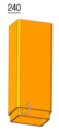
도 5 및 도 7에 도시된 바와 같이, 상기 연장 몸체(240)는 상부방향으로 파형관(300)을 더 매립하고자 할 때 이용하는 것이다. 따라서, 연장 몸체(240)는 몸체(210)의 상단 내부에 끼워져 고정되는 하부 구조와 몸체(210)와 동일한 폭과 길이를 갖는 중공형의 파이프 형태로 구성된다. 즉, 연장 몸체(240) 또한 파형관(300) 간의 좌우 이격거리 유지와 상하 되메우기의 기준선을 제시하도록, 몸체(210)와 동일한 폭과 길이를 갖는 중공형으로 구성한 것이다. 상기의 동일한 길이는 하부 구조를 제외한 길이를 의미한다. 한편, 연장 몸체(240)의 하부 구조는 몸체(210)의 상단 내부에 끼워져 고정될 수 있도록 연장 몸체(240)의 표면에 대해 단차진 형태를 갖는다.As shown in FIGS. 5 and 7 , the
도 5 및 도 8에 도시된 바와 같이, 상기 마감 덮개(250)는 상술한 몸체(210) 또는 연장 몸체(240)의 상단 내부에 끼워져 중공부분의 상부를 덮어 내부로의 이물질 등의 유입을 차단하는 역할을 한다.As shown in FIGS. 5 and 8, the
도 9 내지 도 12에 도시된 바와 같이, 이 실시예의 파형관 이격 스페이서(200)를 이용해 근접 파형관(300) 간의 좌우 및 상하 이격거리를 유지한 상태로 다수개의 파형관(300)을 매립할 수가 있다. As shown in FIGS. 9 to 12 , a plurality of
이 실시예의 파형관 이격 스페이서(200)는 근접 파형관(300)의 측면에 각각 밀착되어 좌우 파형관(300) 간의 좌우 이격거리를 유지함과 더불어, 상하 파형관(300) 간의 상하 되메우기의 기준선 제시를 통해 상하 파형관(300) 간에 항상 일정한 상하 이격거리로 파형관(300)을 매립할 수 있도록 한다. 즉, 이 실시예의 파형관 이격 스페이서(200)는 파형관(300)을 상하좌우 어느 방향으로도 구속하지 않으므로 지반 침하시에도 스페이서로 인해 파형관이 꺾일 염려가 전혀 없어 파형관의 재시공 작업을 줄이고 케이블을 파형관 내부로 편리하면서 원활하게 포설할 수 있을 뿐만 아니라, 파형관(300) 간의 좌우 이격거리를 항상 유지할 수 있어서 파형관(300) 간의 충돌 및 그로 인한 파손 등을 예방할 수가 있다. The corrugated
또한, 이 실시예의 파형관 이격 스페이서(200)는 몸체(210)를 중공형으로 구성함에 따라 다수개의 케이블로 인해 파형관의 내부에서 발생하는 열을 중공형의 통로를 따라 지중 및/또는 외부로 빠르게 분사 및/또는 발산할 수 있어서, 과열로 인한 파형관의 피해를 예방할 수가 있다.In addition, as the corrugated
또한, 이 실시예의 파형관 이격 스페이서(200)는 필요에 따라 연장 몸체(240)를 몸체(210)의 상단 내부에 끼워 조립하는 조립식 구조이므로, 조립 및 해체가 편리하다. In addition, since the corrugated
이상에서 이 고안의 파형관 이격 스페이서에 대한 기술사항을 첨부도면과 함께 서술하였지만 이는 이 고안의 가장 양호한 실시예를 예시적으로 설명한 것이다. 따라서, 이 고안이 상기에 기재된 실시예에 한정되는 것은 아니고, 이 고안의 사상 및 범위를 벗어나지 않고 다양하게 수정 및 변형할 수 있음은 이 기술분야에서 통상의 지식을 가진 자에게 자명하므로, 그러한 변형예 또는 수정예들 또한 이 고안의 청구범위에 속한다 할 것이다.In the above, the technical details of the corrugated pipe spacing spacer of this design have been described together with the accompanying drawings, but this is an example of the best embodiment of this design. Therefore, this invention is not limited to the above-described embodiments, and it is obvious to those skilled in the art that various modifications and variations can be made without departing from the spirit and scope of the invention, so such modifications Examples or modifications will also fall within the scope of the claims of this invention.
200 : 스페이서 210 : 몸체
211 : 보강리브 220 : 돌출부
230 : 지지부 231 : 돌기
240 : 연장 몸체 250 : 마감 덮개
300 : 파형관200: spacer 210: body
211: reinforcing rib 220: protrusion
230: support 231: protrusion
240: extension body 250: closing cover
300: corrugated tube
Claims (6)
지중에 원활하게 박히도록 상기 몸체의 하단에서 하부방향으로 뾰족하게 돌출되는 돌출부와;
지면과의 접촉면적을 증대시키도록 상기 몸체의 하단과 상기 돌출부의 사이에 위치하되, 상기 몸체의 하단 둘레에 상기 몸체와 직교방향으로 외측으로 연장하여 형성되는 지지부와;
상기 몸체의 상단 내부에 끼워져 고정되는 단차진 형태의 하부 구조와 상기 몸체와 동일한 폭과 길이를 갖는 1개 이상의 파이프 형태의 중공형의 연장 몸체; 및
상기 연장 몸체의 상단 내부에 끼워지는 마감 덮개를 포함하는 것을 특징으로 하는 파형관 이격 스페이서.A pipe-shaped hollow hole having a width that adheres to the side surfaces of the left and right corrugated tubes to be buried in the left and right directions to maintain the left and right separation distance between the left and right corrugated tubes and a length that presents a reference line for vertical backfilling between the upper and lower corrugated tubes to be buried in the vertical direction. brother's body;
a protrusion protruding sharply downward from the lower end of the body so as to be smoothly embedded in the ground;
a support portion positioned between the lower end of the body and the protruding part to increase a contact area with the ground, and extending outwardly around the lower end of the body in a direction orthogonal to the body;
One or more pipe-shaped hollow extension bodies having the same width and length as the body and a stepped lower structure inserted into and fixed to the upper end of the body; and
Corrugated pipe spacing spacer, characterized in that it comprises a closing cover fitted inside the upper end of the extension body.
상기 지지부는 하부방향으로 뾰족하게 돌출되는 다수개의 돌기를 더 구비하는 것을 특징으로 하는 파형관 이격 스페이서.The method of claim 1,
The corrugated pipe spacing spacer, characterized in that the support further comprises a plurality of protrusions protruding pointedly downward.
상기 몸체는 사각형 단면 형태를 가지며, 상기 몸체 중에서 상기 좌우 파형관과 밀착하는 표면에는 폭방향으로 다수개의 보강리브가 더 돌출 형성되는 것을 특징으로 하는 파형관 이격 스페이서.The method of claim 4,
The corrugated tube spacing spacer, characterized in that the body has a rectangular cross-section, and a plurality of reinforcing ribs are formed to protrude further in the width direction on the surface of the body in close contact with the left and right corrugated tubes.
상기 지지부는 상기 좌우 파형관이 밀착하는 표면 쪽에만 형성되는 것을 특징으로 하는 파형관 이격 스페이서.The method of claim 5,
The corrugated pipe spacing spacer, characterized in that the support portion is formed only on the surface side to which the left and right corrugated pipes are in close contact.
Priority Applications (1)
| Application Number | Priority Date | Filing Date | Title |
|---|---|---|---|
| KR2020210002802U KR200496715Y1 (en) | 2021-09-10 | 2021-09-10 | Spacer to separate corrugated pipes |
Applications Claiming Priority (1)
| Application Number | Priority Date | Filing Date | Title |
|---|---|---|---|
| KR2020210002802U KR200496715Y1 (en) | 2021-09-10 | 2021-09-10 | Spacer to separate corrugated pipes |
Publications (2)
| Publication Number | Publication Date |
|---|---|
| KR20230000572U KR20230000572U (en) | 2023-03-17 |
| KR200496715Y1 true KR200496715Y1 (en) | 2023-04-10 |
Family
ID=85727856
Family Applications (1)
| Application Number | Title | Priority Date | Filing Date |
|---|---|---|---|
| KR2020210002802U KR200496715Y1 (en) | 2021-09-10 | 2021-09-10 | Spacer to separate corrugated pipes |
Country Status (1)
| Country | Link |
|---|---|
| KR (1) | KR200496715Y1 (en) |
Citations (2)
| Publication number | Priority date | Publication date | Assignee | Title |
|---|---|---|---|---|
| JP2004084766A (en) * | 2002-08-26 | 2004-03-18 | Totaku Industries Inc | Method for burying underground pipe body |
| KR200359150Y1 (en) * | 2004-04-13 | 2004-08-21 | 아이월드 주식회사 | Pipe fixing apparatus |
Family Cites Families (2)
| Publication number | Priority date | Publication date | Assignee | Title |
|---|---|---|---|---|
| KR200194962Y1 (en) | 2000-02-29 | 2000-09-01 | 제룡산업주식회사 | Spacer for ripple mark pipe |
| KR200429651Y1 (en) | 2006-07-21 | 2006-10-25 | 제룡산업 주식회사 | Spacer for fixing corrugated pipe |
-
2021
- 2021-09-10 KR KR2020210002802U patent/KR200496715Y1/en active IP Right Grant
Patent Citations (2)
| Publication number | Priority date | Publication date | Assignee | Title |
|---|---|---|---|---|
| JP2004084766A (en) * | 2002-08-26 | 2004-03-18 | Totaku Industries Inc | Method for burying underground pipe body |
| KR200359150Y1 (en) * | 2004-04-13 | 2004-08-21 | 아이월드 주식회사 | Pipe fixing apparatus |
Also Published As
| Publication number | Publication date |
|---|---|
| KR20230000572U (en) | 2023-03-17 |
Similar Documents
| Publication | Publication Date | Title |
|---|---|---|
| US4601447A (en) | Conduit spacer anchoring system | |
| KR101587272B1 (en) | Protecting tube for distribution line in underground | |
| JP7190840B2 (en) | Bifurcation forming device, bifurcation structure, common groove, and method of forming bifurcation | |
| KR20120067756A (en) | Pipe fixing system | |
| KR200496715Y1 (en) | Spacer to separate corrugated pipes | |
| KR101081380B1 (en) | Street post foundation | |
| KR101584306B1 (en) | Precast culvert | |
| KR101089099B1 (en) | Cable Trough | |
| KR200439820Y1 (en) | Cable Protection Tube | |
| JP7306848B2 (en) | Branch pipe joint installation structure and construction method | |
| KR20220000115U (en) | Spacer for fixing corrugated pipe | |
| JP4491386B2 (en) | Underground wiring box | |
| KR101480707B1 (en) | outlet box for conduit connecting | |
| KR101000533B1 (en) | Spacer for fixing Corrugated Pipe | |
| KR100776778B1 (en) | Spacer for protecting and fixing of corrugated tube in transmission/distribution | |
| JP2004120874A (en) | Trough for multipurpose duct of electric cable | |
| KR20080050055A (en) | Prefabricated cable tray | |
| KR200436059Y1 (en) | Outlet box for wall | |
| KR102561028B1 (en) | Generation Terminal Box with Excellent Combination and Waterproof Performance | |
| KR20000077152A (en) | Synthetic resin pipe body | |
| KR20120051299A (en) | Drainage panel | |
| KR200228999Y1 (en) | A cable duct | |
| RU213009U1 (en) | ACCESS WELL | |
| KR101407503B1 (en) | Ground reinforcement device and retaining wall by using of it) | |
| KR200286929Y1 (en) | Pipe conduit for subterranean cable |
Legal Events
| Date | Code | Title | Description |
|---|---|---|---|
| E701 | Decision to grant or registration of patent right | ||
| REGI | Registration of establishment |