KR200492650Y1 - Integrated air pump - Google Patents
Integrated air pump Download PDFInfo
- Publication number
- KR200492650Y1 KR200492650Y1 KR2020190001167U KR20190001167U KR200492650Y1 KR 200492650 Y1 KR200492650 Y1 KR 200492650Y1 KR 2020190001167 U KR2020190001167 U KR 2020190001167U KR 20190001167 U KR20190001167 U KR 20190001167U KR 200492650 Y1 KR200492650 Y1 KR 200492650Y1
- Authority
- KR
- South Korea
- Prior art keywords
- air
- manifold
- disposed
- component
- valve
- Prior art date
Links
- 230000001105 regulatory effect Effects 0.000 claims abstract description 23
- 230000003584 silencer Effects 0.000 claims description 11
- 238000000034 method Methods 0.000 claims description 9
- 230000005540 biological transmission Effects 0.000 claims description 7
- 230000006835 compression Effects 0.000 claims description 6
- 238000007906 compression Methods 0.000 claims description 6
- 230000000694 effects Effects 0.000 claims description 6
- 230000004308 accommodation Effects 0.000 claims description 3
- 238000013022 venting Methods 0.000 claims description 2
- 238000004891 communication Methods 0.000 description 3
- 238000009423 ventilation Methods 0.000 description 3
- 229920000742 Cotton Polymers 0.000 description 1
- 230000000903 blocking effect Effects 0.000 description 1
- 230000001276 controlling effect Effects 0.000 description 1
- 238000007599 discharging Methods 0.000 description 1
- 238000009434 installation Methods 0.000 description 1
- 238000011900 installation process Methods 0.000 description 1
- 230000007774 longterm Effects 0.000 description 1
- 239000000463 material Substances 0.000 description 1
- 239000011148 porous material Substances 0.000 description 1
- 238000007789 sealing Methods 0.000 description 1
Images


Classifications
-
- F—MECHANICAL ENGINEERING; LIGHTING; HEATING; WEAPONS; BLASTING
- F04—POSITIVE - DISPLACEMENT MACHINES FOR LIQUIDS; PUMPS FOR LIQUIDS OR ELASTIC FLUIDS
- F04B—POSITIVE-DISPLACEMENT MACHINES FOR LIQUIDS; PUMPS
- F04B27/00—Multi-cylinder pumps specially adapted for elastic fluids and characterised by number or arrangement of cylinders
- F04B27/08—Multi-cylinder pumps specially adapted for elastic fluids and characterised by number or arrangement of cylinders having cylinders coaxial with, or parallel or inclined to, main shaft axis
- F04B27/10—Multi-cylinder pumps specially adapted for elastic fluids and characterised by number or arrangement of cylinders having cylinders coaxial with, or parallel or inclined to, main shaft axis having stationary cylinders
-
- F—MECHANICAL ENGINEERING; LIGHTING; HEATING; WEAPONS; BLASTING
- F04—POSITIVE - DISPLACEMENT MACHINES FOR LIQUIDS; PUMPS FOR LIQUIDS OR ELASTIC FLUIDS
- F04B—POSITIVE-DISPLACEMENT MACHINES FOR LIQUIDS; PUMPS
- F04B39/00—Component parts, details, or accessories, of pumps or pumping systems specially adapted for elastic fluids, not otherwise provided for in, or of interest apart from, groups F04B25/00 - F04B37/00
- F04B39/0027—Pulsation and noise damping means
- F04B39/0055—Pulsation and noise damping means with a special shape of fluid passage, e.g. bends, throttles, diameter changes, pipes
- F04B39/0061—Pulsation and noise damping means with a special shape of fluid passage, e.g. bends, throttles, diameter changes, pipes using muffler volumes
-
- F—MECHANICAL ENGINEERING; LIGHTING; HEATING; WEAPONS; BLASTING
- F04—POSITIVE - DISPLACEMENT MACHINES FOR LIQUIDS; PUMPS FOR LIQUIDS OR ELASTIC FLUIDS
- F04B—POSITIVE-DISPLACEMENT MACHINES FOR LIQUIDS; PUMPS
- F04B39/00—Component parts, details, or accessories, of pumps or pumping systems specially adapted for elastic fluids, not otherwise provided for in, or of interest apart from, groups F04B25/00 - F04B37/00
- F04B39/10—Adaptations or arrangements of distribution members
-
- F—MECHANICAL ENGINEERING; LIGHTING; HEATING; WEAPONS; BLASTING
- F05—INDEXING SCHEMES RELATING TO ENGINES OR PUMPS IN VARIOUS SUBCLASSES OF CLASSES F01-F04
- F05B—INDEXING SCHEME RELATING TO WIND, SPRING, WEIGHT, INERTIA OR LIKE MOTORS, TO MACHINES OR ENGINES FOR LIQUIDS COVERED BY SUBCLASSES F03B, F03D AND F03G
- F05B2210/00—Working fluid
- F05B2210/10—Kind or type
- F05B2210/12—Kind or type gaseous, i.e. compressible
-
- F—MECHANICAL ENGINEERING; LIGHTING; HEATING; WEAPONS; BLASTING
- F05—INDEXING SCHEMES RELATING TO ENGINES OR PUMPS IN VARIOUS SUBCLASSES OF CLASSES F01-F04
- F05B—INDEXING SCHEME RELATING TO WIND, SPRING, WEIGHT, INERTIA OR LIKE MOTORS, TO MACHINES OR ENGINES FOR LIQUIDS COVERED BY SUBCLASSES F03B, F03D AND F03G
- F05B2210/00—Working fluid
- F05B2210/16—Air or water being indistinctly used as working fluid, i.e. the machine can work equally with air or water without any modification
-
- F—MECHANICAL ENGINEERING; LIGHTING; HEATING; WEAPONS; BLASTING
- F05—INDEXING SCHEMES RELATING TO ENGINES OR PUMPS IN VARIOUS SUBCLASSES OF CLASSES F01-F04
- F05B—INDEXING SCHEME RELATING TO WIND, SPRING, WEIGHT, INERTIA OR LIKE MOTORS, TO MACHINES OR ENGINES FOR LIQUIDS COVERED BY SUBCLASSES F03B, F03D AND F03G
- F05B2260/00—Function
- F05B2260/30—Retaining components in desired mutual position
-
- F—MECHANICAL ENGINEERING; LIGHTING; HEATING; WEAPONS; BLASTING
- F05—INDEXING SCHEMES RELATING TO ENGINES OR PUMPS IN VARIOUS SUBCLASSES OF CLASSES F01-F04
- F05B—INDEXING SCHEME RELATING TO WIND, SPRING, WEIGHT, INERTIA OR LIKE MOTORS, TO MACHINES OR ENGINES FOR LIQUIDS COVERED BY SUBCLASSES F03B, F03D AND F03G
- F05B2260/00—Function
- F05B2260/96—Preventing, counteracting or reducing vibration or noise
- F05B2260/962—Preventing, counteracting or reducing vibration or noise by means creating "anti-noise"
Abstract
일체형 공기 펌프는 공기 공급 구성 요소, 공기 가이드 구성 요소, 스위칭 밸브, 및 압력 조절 구성 요소를 포함한다. 공기 가이드 구성 요소는 공기 공급 구성 요소 상에 장착되고, 공기 가이드 시트 및 일 방향 밸브를 포함한다. 공기 가이드 시트에는 공기 유로가 형성되며, 일 방향 밸브는 공기 유로에 대응하여 배치되고 공기 공급 포트 및 공기 배출 구역에 연결된 공기 유입 구역을 정의하도록 공기 유로를 만든다. 스위칭 밸브는 공기 배출 구역에 연결되며, 압력 조절 구성 요소는 공기 유로로부터 갈라지는 공기 안내 매니폴드에 연결되고, 공기 유로는 내부의 공기 압력이 과도하게 클 때 수축될 수 있다.The integral air pump includes an air supply component, an air guide component, a switching valve, and a pressure regulating component. The air guide component is mounted on the air supply component and includes an air guide seat and a one-way valve. An air flow path is formed in the air guide seat, and the one-way valve is disposed to correspond to the air flow path and creates an air flow path to define an air inlet region connected to the air supply port and the air discharge region. The switching valve is connected to the air discharge zone, the pressure regulating component is connected to an air guide manifold that diverges from the air flow path, and the air flow path can be retracted when the air pressure inside is excessively large.
Description
본 고안은 공기 펌프에 관한 것으로, 보다 상세하게는 일체형 공기 펌프에 관한 것이다. The present invention relates to an air pump, and more particularly, to an integrated air pump.
종래의 공기 공급 모듈은 중국 특허 No. CN102817819B에 개시된 바와 같이 하나의 공기 펌프만을 포함한다. 공기 공급 모듈이 충전하거나 팽창되는 물체를 수축시키는데 사용되는 경우, 공기 공급 모듈에는 공기의 충전 및 방전을 제어하기 위한 스위칭 밸브(switching valve)가 추가로 제공될 필요가 있다. 즉 말하자면, 설치 과정 중에, 스위칭 밸브와 공기 공급 모듈이 동시에 조립 공간 상에 설치되어야 하며, 그리고 조립 공간이 협소하면, 장치들을 내부에 동시에 설치할 수 없으므로 공기 공급 모듈을 사용할 수 없게 된다. The conventional air supply module is a Chinese patent No. It contains only one air pump as disclosed in CN102817819B. When the air supply module is used to constrict an object to be charged or inflated, the air supply module needs to be additionally provided with a switching valve for controlling the charging and discharging of air. That is, during the installation process, the switching valve and the air supply module must be installed on the assembly space at the same time, and if the assembly space is narrow, the air supply module cannot be used because the devices cannot be installed at the same time inside.
반면에, 종래의 공기 공급 모듈에 언제든지 공기 펌프에 의해 발생되는 가스 압력을 감지하는 압력 감지 장치가 추가 되어야한다. 그러나 압력 감지 장치는 장기적으로 엔지니어링 직원에 의해 관찰되어지고 감시되어야 한다. 즉 말하자면, 상기 공기 공급 모듈은 생성된 가스를 설정된 공기 압력 값 내에서 유지할 수 없다. 만일 추가 압력 감지 장치가 종래의 공기 펌프에 추가되면, 설치가 더 어려워질 것이다. 그러나, 장치의 체적을 줄이기 위해 압력 감지 장치가 폐기되면, 팽창되는 물체가 과도하게 팽창될 수 있다. On the other hand, a pressure sensing device for detecting the gas pressure generated by the air pump at any time must be added to the conventional air supply module. However, pressure sensing devices must be observed and monitored by engineering personnel over the long term. In other words, the air supply module cannot maintain the generated gas within the set air pressure value. If an additional pressure sensing device is added to the conventional air pump, the installation will be more difficult. However, if the pressure-sensing device is discarded to reduce the volume of the device, the inflated object may be excessively expanded.
본 고안의 주된 목적은 추가적인 구조가 더해져야 하는 종래의 공기 공급에 의해 유발되는 문제점을 해결하는 것이다.The main object of the present invention is to solve the problem caused by the conventional air supply in which an additional structure must be added.
상기 목적을 달성하기 위해, 본 고안은 공기 공급 구성 요소, 공기 가이드 구성 요소, 스위칭 밸브, 및 압력 조절 구성 요소를 포함하는 일체형 공기 펌프를 제공한다. 공기 공급 구성 요소는 공기 공급 포트를 포함한다. 공기 가이드 구성 요소는 공기 공급 구성 요소에 장착되며, 공기 가이드 시트와 일 방향 밸브를 포함한다. 상기 공기 가이드 시트는 공기 유로와 함께 형성되고, 상기 일 방향 밸브는 상기 유로에 대응하여 배치되고 상기 유로를 상기 공급 포트 및 공기 배출 구역에 연결하는 공기 유입 구역으로 정의하도록 한다. 공기 유로의 공기 유입 구역은 공기 공급 포트에 연결되는 공기 입구 통로, 및 공기 입구 통로와 연통하는 공기 안내 매니폴드를 포함한다. 상기 일 방향 밸브는 밸브 시트, 밸브 시트에 형성된 통기공, 및 밸브 시트에 결합되고 통기공에 대치하여 배치된 밸브 플레이트를 포함한다. 상기 밸브 플레이트는 공기 배출 구역의 역류 현상에 의해 통기공이 차폐되어 상기 통기공을 통과하는 기류를 제한하는 역전 상태를 포함하며, 공기 유입 구역의 전방 기류 효과에 의해 통기공이 해제되어 기류가 통기공을 통과하게 허용하는 통기 상태를 포함한다. 스위칭 밸브는 공기 배출 구역에 연결되는 공기 출구 통로, 공기 출구 통로와 함께 연통하는 공기 팽창 매니폴드, 공기 출구 통로와 함께 연통하는 공기 배출 매니폴드, 공기 출구 통로에 배치된 밸브 블록, 상기 밸브 블록에 연결되어 밸브 블록을 공기 배출 매니폴드 쪽으로 밀게하는 제 1 스프링, 및 밸브 블록에 대응하여 배치된 전자석을 포함한다. 상기 스위칭 밸브는 전자석에 의해 끌어당겨지지 않아서 공기 배출 매니폴드를 차단하여 기류가 공기 팽창 매니폴드로 들어가도록 허용하는 제 1상태를 포함하고, 전자석에 의해 끌어당겨져서 공기 배출 구역을 막고 공기 배출 구역 내 기류가 공기 배출 매니폴드로부터 배출되도록 유발하는 제 2상태를 포함한다. 압력 조절 구성 요소는 공기 가이드 시트에 연결된 장착 커버, 장착 커버에 배치된 공기 릴리프 구멍, 공기 안내 매니폴드에 대응하여 배치된 피스톤, 및 장착 커버와 피스톤에 연결되고 피스톤에 인접한 작용력을 공급하는 제 2 스프링을 포함한다. 상기 압력 조절 구성 요소는 공기 안내 매니폴드 내 공기 압력이 인접한 작용력보다 작은 경우일 때 공기 안내 매니폴드가 피스톤에 의해 막히는 공기 정지 상태를 포함하고, 공기 안내 매니폴드 내 공기 압력이 인접한 작용력보다 큰 경우일 때 피스톤이 제 2 스프링을 압축하여 공기 안내 매니폴드와 공기 릴리프 구멍을 연통하게 하는 압력 조절 상태를 포함한다. In order to achieve the above object, the present invention provides an integrated air pump including an air supply component, an air guide component, a switching valve, and a pressure regulating component. The air supply component includes an air supply port. The air guide component is mounted on the air supply component and includes an air guide seat and a one-way valve. The air guide seat is formed together with an air flow path, and the one-way valve is disposed to correspond to the flow path, and defines the flow path as an air inlet zone connecting the supply port and the air discharge zone. The air inlet section of the air flow path includes an air inlet passage connected to the air supply port, and an air guide manifold in communication with the air inlet passage. The one-way valve includes a valve seat, a vent hole formed in the valve seat, and a valve plate coupled to the valve seat and disposed to face the vent hole. The valve plate includes a reversing state in which the ventilation hole is blocked by the reverse flow phenomenon of the air discharge area to limit the airflow passing through the ventilation hole, and the ventilation hole is released by the front airflow effect of the air inflow area to allow the airflow Includes a ventilated condition that allows it to pass through the pores. The switching valve includes an air outlet passage connected to the air outlet passage, an air expansion manifold communicating with the air outlet passage, an air outlet manifold communicating with the air outlet passage, a valve block disposed in the air outlet passage, and the valve block. And a first spring connected to push the valve block toward the air discharge manifold, and an electromagnet disposed corresponding to the valve block. The switching valve comprises a first state that is not pulled by the electromagnet to block the air discharge manifold to allow airflow to enter the air expansion manifold, and is attracted by the electromagnet to block the air discharge zone and the air discharge zone It includes a second condition that causes the internal airflow to be discharged from the air exhaust manifold. The pressure regulating component includes a mounting cover connected to the air guide seat, an air relief hole disposed in the mounting cover, a piston disposed corresponding to the air guide manifold, and a second connected to the mounting cover and the piston and supplying an acting force adjacent the piston. Includes spring. The pressure regulating component includes an air stop state in which the air guide manifold is blocked by a piston when the air pressure in the air guide manifold is less than the adjacent force, and when the air pressure in the air guide manifold is greater than the adjacent force. When the piston compresses the second spring, it includes a pressure adjustment state in which the air guide manifold communicates with the air relief hole.
일 실시예에서, 장착 커버는 제 1 나사산과 함께 형성되며, 상기 공기 가이드 시트는 제 1 나사산에 결합되는 제 2 나사산을 포함한다.In one embodiment, the mounting cover is formed with a first thread, and the air guide sheet includes a second thread coupled to the first thread.
일 실시예에서, 상기 스위칭 밸브는 공기 배출 매니폴드에 대응되게 배치된 제 1 배기 소음기를 포함한다. In one embodiment, the switching valve includes a first exhaust silencer disposed to correspond to the air exhaust manifold.
일 실시예에서, 상기 압력 조절 구성 요소는 공기 릴리프 구멍에 대응하여 배치된 제 2배기 소음기를 포함한다. In one embodiment, the pressure regulating component includes a second exhaust silencer disposed corresponding to the air relief hole.
일 실시예에서, 상기 공기 공급 구성 요소는 공기 공급 포트의 동일 측면 상에 배치된 적어도 하나의 장착 포스트, 및 장착 포스트에 연결된 적어도 하나의 포지셔닝 피스(Positioning piece)를 포함하며, 공기 가이드 시트는 장착 포스트와 조립된 적어도 하나의 장착 구멍, 및 상기 장착 구멍에 연결되고 상기 포지셔닝 피스와 조립되는 포지셔닝 그루브(Positioning groove)을 포함한다. In one embodiment, the air supply component includes at least one mounting post disposed on the same side of the air supply port, and at least one positioning piece connected to the mounting post, wherein the air guide sheet is mounted At least one mounting hole assembled with the post, and a positioning groove connected to the mounting hole and assembled with the positioning piece.
일 실시예에서, 공기 공급 구성 요소는 공기 펌프, 및 공기 펌프에 연결되고 공기 공급 포트와 함께 형성된 공기 통로 플레이트를 포함한다. In one embodiment, the air supply component includes an air pump and an air passage plate connected to the air pump and formed with an air supply port.
일 실시예에서, 상기 공기 펌프는 모터, 모터에 연결되고 중공 수용 공간과 함께 형성된 공기 펌프 하우징, 및 중공 수용 공간 내에 배치된 가스 압축 구성 요소를 포함한다. 상기 모터는 출력 샤프트와 출력 샤프트에 배치된 전달 블록을 포함하며, 전달 블록은 사선의 장착 구멍에 편심으로 배치된다. 상기 가스 압축 구성 요소는 출력 샤프트가 회전할 때에 런아웃(runout)을 유발하고 사선의 장착 구멍에 배치된 구동 부재, 및 각각 구동 부재에 연결되고 구동 부재를 따라 가변적 용량을 발생시키는 복수의 에어백들을 포함한다. In one embodiment, the air pump includes a motor, an air pump housing connected to the motor and formed with a hollow receiving space, and a gas compression component disposed within the hollow receiving space. The motor includes an output shaft and a transmission block disposed on the output shaft, the transmission block being eccentrically disposed in a diagonal mounting hole. The gas compression component includes a drive member that causes runout when the output shaft rotates and is disposed in a diagonal mounting hole, and a plurality of airbags each connected to the drive member and generating a variable capacity along the drive member. do.
전술 한 내용에 따르고, 종래 기술과 비교하여, 본 고안은 다음의 특징을 포함한다: 공기 가이드 구성 요소, 스위칭 밸브 및 공기 공급 구성 요소 상의 압력 조절 구성 요소를 조립함으로써, 일체형 공기 펌프는 추가적인 구조 및 튜브없이 장치의 체적을 상당히 감소시킨다. 또한, 일체형 공기 펌프는 압력 조절 구성 요소의 설정을 통해 최대 출력 공기 압력을 유지한다.In accordance with the foregoing, and compared with the prior art, the present invention includes the following features: By assembling the air guide component, the switching valve and the pressure regulating component on the air supply component, the integral air pump has an additional structure and Significantly reduces the volume of the device without tubes In addition, the integral air pump maintains the maximum output air pressure through the setting of the pressure regulating component.
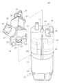
도 1은 본 고안의 일 실시예의 구조적 사시도이다;
도 2은 본 고안의 일 실시예의 제 1 구조적 분해도이다;
도 3은 본 고안의 일 실시예의 제 2 구조적 분해도이다;
도 4은 본 고안의 일 실시예의 구성 요소 구조의 제 1 단면도이다.
도 5은 본 고안의 일 실시예의 구성 요소 구조의 제 2 단면도이다; 그리고
도 6은 본 고안의 일 실시예의 구성 요소 구조의 제 3단면도이다. 1 is a structural perspective view of an embodiment of the present invention;
2 is a first structural exploded view of an embodiment of the present invention;
3 is a second structural exploded view of an embodiment of the present invention;
4 is a first cross-sectional view of a component structure of an embodiment of the present invention.
5 is a second cross-sectional view of a component structure of an embodiment of the present invention; And
6 is a third cross-sectional view of a component structure of an embodiment of the present invention.
본 고안의 상세한 설명 및 기술적 내용은 첨부 된 도면을 참조하여 다음과 같이 설명 될 것이다:Detailed description and technical content of the present invention will be described as follows with reference to the accompanying drawings:
도 1, 2, 3 및 4를 참조하면, 본 고안은 일체형 공기 펌프(100)를 제공하며, 일체형 공기 펌프(100)는 공기 공급 구성 요소(10), 공기 가이드 구성 요소(20), 스위칭 밸브(30) 및 압력 조절 구성 요소(40)를 포함한다. 구체적으로, 공기 공급 구성 요소(10)는 공기 가이드 구성 요소(20) 반대편에 배치된 공기 공급 포트(11)와 함께 형성되며, 작동 후에 공기 공급 구성 요소(10)는 공기 공급 포트(11)로부터 배출되는 가스를 발생시킬 수 있다. 또한, 공기 가이드 구성 요소(20)는 그 내부 가스를 수용하기 위해 공기 공급 구성 요소(10)상에 배치된다. 상세하게, 공기 가이드 구성 요소(20)는 공기 가이드 시트(21)와 일 방향 밸브(22)를 포함한다. 상기 공기 가이드 시트(21)는 공기 공급 포트(11)에 대응하여 배치되고 공기 유로(211)와 함께 제공된다. 일 방향 밸브(22)는 공기 유로(211)에 대응하여 배치되어 상기 공기 유로(211)는 공기 공급 포트(11) 및 공기 배출 구역(213)에 연결되는 공기 유입 구역(212)을 정의한다. 뿐만 아니라, 공기 유입 구역(212)과 공기 배출 구역(213)은 일 방향 밸브(22)에 의해 분리된다. 도 4의 지시에 기초하여 참조하면, 일 방향 밸브(22) 아래에는 공기 유입 구역(212)이 있고, 일 방향 밸브(22) 위에는 공기 배출 구역(213)이 있다. 뿐만 아니라, 공기 유로(211)의 공기 유입 구역(212)은 공기 공급 포트(11)에 연결되는 공기 입구 통로(214)와 상기 공기 입구 통로(214)에 연결되는 공기 안내 매니폴드(215)와 함께 배치되며; 상기 공기 안내 매니폴드(215)는 공기 입구 통로 (214)와 연통한다. 즉, 가스가 공기 유로(211)로 유입되면, 공기 안내 매니폴드(215) 안의 압력은 공기 입구 통로(214) 안의 압력과 동일하다. 또한, 일 방향 밸브(22)는 밸브 시트(221), 밸브 시트(221)에 형성된 통기공(222), 및 밸브 시트(221)에 결합되고 통기공(222) 반대편에 배치된 밸브 플레이트(223)를 포함한다. 일 방향 밸브(22)는 공기 유로(211) 내에 배치되고 상기 공기 유로(211)에서 기류 효과를 받아서 기류 방향에 따라 밸브 플레이트 (223)가 통기 상태와 역전 상태가 된다. 상세하게, 가스가 공기 입구 통로(214)로부터 공기 배출 구역(213)을 향해 유동할 때, 전방 기류로 정의되며, 그리고 역으로, 가스가 공기 배출 구역(213)으로부터 공기 입구 통로(214)를 향해 유동할 때, 역전 기류로 정의된다. 밸브 플레이트(223)는 전방 기류 효과를 받을 때 통기 상태로 되고, 역전 기류 효과를 받을 때 역전 상태로 된다. 뿐만 아니라, 통기 상태일 때, 밸브 플레이트(223)가 변형되어 통기공(222)이 개방되어 공기 유입 구역(212)이 공기 배출 구역(213)과 연통되는 것을 유발하며; 역전 상태일 때, 밸브 플레이트(223)는 가스에 의해 밀리지 않으며 공기 차단 효과를 얻기 위해 밸브 시트(221)에 부착된다. 1, 2, 3 and 4, the present invention provides an integrated
다른 한편으로는, 스위칭 밸브(30)는 공기 가이드 시트(21) 상에 조립되며, 공기 배출 구역(213)에 연결되는 공기 출구 통로(31), 공기 출구 통로(31)와 함께 연통하는 공기 팽창 매니폴드(32), 공기 출구 통로(31)와 연통하는 공기 배출 매니폴드(33), 공기 출구 통로(31) 내에 배치된 밸브 블록(34), 상기 밸브 블록(34)에 연결되고 밸브 블록(34)이 공기 배출 매니폴드(33)를 향해 밀게 하는 제 1 스프링(35), 및 공기 출구 통로(31) 내에 위치되고 밸브 블록(34)에 대응하여 배치되는 전자석(36)을 포함한다. 뿐만 아니라, 스위칭 밸브(30)는 전자석(36)에 의해 끌어당겨지지 않은 제 1 상태와 전자석(36)에 의해 끌어당겨진 제 2 상태를 포함한다. 제 1 상태에서, 스위칭 밸브(30)는 공기 배출 매니폴드(33)를 차폐한다. 또한, 제 2 상태에서는, 스위칭 밸브(30)가 공기 배출 구역(213)을 막는다.On the other hand, the
다른 한편으로는, 압력 조절 구성 요소(40)는 공기 가이드 시트(21)의 측면에 연결되며, 상기 공기 가이드 시트(21)에 연결되는 장착 커버 (41), 상기 장착 커버(41)에 배치된 공기 릴리프 구멍(42), 상기 공기 안내 매니폴드 (215)에 대응하여 배치된 피스톤(43), 및 피스톤(43) 상에 조립되고 장착 커버(41)에 연결되고 피스톤(43)에 대한 인접한 작용력을 제공하는 제 2 스프링(44)을 포함한다. 상세하게, 피스톤(43)은 장착 커버(41)에 연결되는 제 1 끝단(431), 및 제 1 끝단 (431)에 연결되는 제 2 끝단(432)으로 분할된다. 공기 안내 매니폴드(215)를 차폐하는 피스톤(43)의 제 2 끝단(432)을 허용하도록, 제 2 끝단(432)의 폭은 공기 안내 매니폴드(215)의 내부 직경보다 크다. 또한, 제 2 스프링(44)은 피스톤(43) 상에 슬리브로 연결되고, 한 끝단과 함께 장착 커버(41)와 접촉하여, 장착 커버(41)에 의해 제 2 스프링(44)이 가압 되어 피스톤(43)에 작용한다. 뿐만 아니라, 압력 조절 구성 요소(40)는 공기 안내 매니폴드(215) 내의 공기 압력이 인접한 작용력보다 작을 때에 공기 안내 매니폴드(215)가 피스톤(43)에 의해 막히는 공기 정지 상태를 포함하며, 공기 안내 매니폴드(215) 내의 공기 압력이 인접한 작용력보다 클 때에 피스톤(43)이 제 2 스프링(44)을 압축하는 압력 조절 상태를 포함한다. 일 실시예에서, 장착 커버(41)는 그 위에 제 1 나사산(411)과 함께 형성되고, 공기 가이드 시트(21)는 제 1 나사산(411)에 결합되는 제 2 나사산(216)을 포함한다. 제 1 나사산(411)과 제 2 나사산(216)의 조립 정도의 차이에 의해, 제 2 스프링(44)은 다양한 정도로 압축되어, 장착 커버(41)는 각각 다른 인접한 작용력을 받는다. 뿐만 아니라, 피스톤(43)은 압력 조절 설정 값을 포함하며, 상기 압력 조절 설정 값은 제 2 스프링(44)의 인접한 작용력에 따라 결정된다. 다른 한편으로는, 엔지니어링 직원은 일체형 공기 펌프(100)에 의해 출력 된 가스 압력이 압력 조절 설정 값 이하로 유지될 수 있도록 장착 커버(41)를 작동시킴으로써 압력 조절 설정 값을 결정할 수 있다.On the other hand, the
다음으로, 일체형 공기 펌프(100)가 팽창되는 대상물에 연결되는 일 실시예가 다음과 같이 설명되며, 도 4, 5 및 6을 참고할 수 있다. 작동 후에 공기 공급 구성 요소(10)가 가스를 발생시키기 시작하면, 가스는 일 방향 밸브(22)의 공기 유로(211)를 따라 진입한다. 이때, 가스는 밸브 플레이트(223)에 관한 전방 기류이며, 그것 때문에 밸브 플레이트(223)가 이동하여 통기 상태로 되며, 가스가 통기공(222)을 통과하여 스위칭 밸브(30)로 진입할 수 있다. 이때, 일단 스위칭 밸브(30)가 제 1 상태에 있게 되면, 팽창되는 대상물이 팽창될 수 있도록, 가스는 공기 출구 통로(31)에서부터 공기 팽창 매니폴드(32)로 진입할 수 있다. 게다가, 스위칭 밸브(30)가 제 2 상태에 있을 때, 가스는 밸브 블록(34)에 의해 차단되고 공기 팽창 매니폴드(32)로 진입할 수 없다. 뿐만 아니라, 상기 실행 과정에서, 공급된 가스의 압력이 압력 조절 구성 요소(40)의 압력 조절 설정 값보다 클 때, 압력 조절 구성 요소(40)는 압력 조절 상태로 진입하고, 그리고 공기 안내 매니폴드(215)는 상기 공기 안내 매니폴드(215)로부터 가스가 배출되도록 허용하는 공기 릴리프 구멍(42)과 연통한다. 공기 유로(211) 내의 압력이 인접한 작용력과 동일한 압력으로 떨어지면, 압력 조절 구성 요소(40)가 압력 조절 상태에서 공기 정지 상태로 변경될 수 있도록 가스는 피스톤(43)을 밀 수 없다, 즉, 가스는 더 이상 공기 안내 매니폴드(215)로부터 배출되지 않으나, 공기 입구 통로 (214)로 완전히 들어가서 일 방향 밸브(22) 및 스위칭 밸브(30)와 접촉한다. 다른 한편으로는, 팽창되는 대상물을 수축시킬 필요가 있는 경우에는, 스위칭 밸브(30)가 제 1 상태로부터 제 2 상태로 변경된다. 이 때, 공기 배출 구역(213) 내의 가스가 공기 배출 매니폴드(33)로부터 배출되도록 공기 팽창 매니폴드(32)는 공기 배출 매니폴드(33)와 연통한다. 이와 동시에, 가스가 제한되어 통기공(222)을 통과할 수 없도록 밸브 플레이트(223)는 통기 상태에서 역전 상태로 전환된다. Next, an embodiment in which the
공기 가이드 구성 요소(20), 스위칭 밸브(30) 및 공기 공급 구성 요소(10) 상에 압력 조절 구성 요소(40)를 조립함으로써, 일체형 공기 펌프(100)는 부가적인 와이어를 사용하지 않고 일체형 구조를 이루므로, 일체형 공기 펌프(100)가 작은 조립 공간에 배치된다. 뿐만 아니라, 일체형 공기 펌프(100)에 의해 출력된 가스 압력은 압력 조절 구성 요소(40)의 설정을 통해 설정 공기 압력 값 이하로 유지될 수 있다. By assembling the
도 4를 다시 참조, 일 실시예에서, 일 방향 밸브(22)가 전방 기류에 의해 밸브 시트 (221)로부터 분리되게 밀고 나가는 것을 방지하기 위해, 일 방향 밸브(22)는 밸브 플레이트(223)에 연결되는 연결 포스트(224), 및 밸브 플레이트(223)에 반대되는 방향으로 배치된 연결 포스트(224)에 연결되는 제한 블록(225)을 포함한다. 상세하게, 연결 포스트(224)는 밸브 시트(221)에 삽입되며, 제한 블록(225)은 밸브 시트(221)의 다른 측면에 배치된다. 밸브 플레이트(223)가 전방 기류에 의해 밀려서 밸브 시트(221)로부터 분리될 때에, 제한 블록(225)은 밸브 플레이트(223)가 분리되도록 제한하면서 밸브 시트(221)에 접한다. Referring again to FIG. 4, in one embodiment, in order to prevent the one-
다른 한편으로는, 상기 스위칭 밸브(30)는 상기 공기 배출 매니폴드(33)에 대응하여 배치된 제 1 배기 소음기(23)를 포함하며, 공기 배출 매니폴드(33)로 진입하는 가스가 제 1 배기 소음기(23)의 영향을 받게 되어 공기 배출량이 감소되도록 한다. 뿐만 아니라, 상기 공기 가이드 구성 요소(20)는 홈(24)과 함께 형성되어 내부에 배치된 제 1 배기 소음기(23)를 제공하며, 상기 홈(24)은 공기 배출 매니폴드(33)에 대응하여 배치되어 공기 배출 매니폴드(33)로부터 가스가 배출된 후에, 제 1 배기 소음기(23)의 영향으로 인해 공기 배출량이 감소되도록 한다. 또한, 압력 조절 구성 요소(40)는 또한 공기 릴리프 구멍(42)에 대응하여 배치된 제 2 배기 소음기(45)를 포함한다. 뿐만 아니라, 제 1 배기 소음기(23) 및 제 2 배기 소음기(45)는 각각 가스가 통과할 수 있는 스폰지 또는 면 재질이다. On the other hand, the switching
도 3 및 4를 다시 참조, 일 실시예에서, 압력 조절 구성 요소(40)에는 피스톤(43)의 끝단에 연결된 보조 밀봉기(46)가 제공된다. 공기 정지 상태에서, 상기 보조 밀봉기(46)는 공기 안내 매니폴드(215) 및 피스톤(43)과 접촉하여 공기 안내 매니폴드(215)의 공기 정지 정도를 증가시킨다. 또한, 일 실시예에서, 상기 스위칭 밸브(30)는 상기 밸브 블록(34)의 양 끝단에 각각 배치된 복수의 보조 공기 정지 부재(37)를 포함한다. 제 1상태에서, 복수의 보조 공기 정지 부재(37)는 밸브 블록(34)이 공기 배출 매니폴드(33)를 막도록 보조하고, 제 2 상태에서 공기 출구 통로(31)를 밀봉하는 것을 보조한다. 뿐만 아니라, 복수의 보조 공기 정지 부재(37)는 가스에 작용하여 가스의 체적을 감소시킨다. Referring again to FIGS. 3 and 4, in one embodiment, the
일 실시예에서, 상기 공기 가이드 구성 요소(20)는 상기 공기 가이드 시트(21)에 연결되는 시트(25)와 함께 형성되며, 시트(25)는 홈(24) 및 공기 팽창 매니폴드(32)와 함께 형성되며, 시트(25)와 스위칭 밸브(30)는 조립 과정에서 서로 조립되어 공기 팽창 매니폴드(32)와 연통하는 스위칭 밸브(30)를 허용한다.In one embodiment, the
다른 한편으로는, 일 실시예에서, 도 3 및 4를 참조하면, 공기 공급 구성 요소(10)는 공기 펌프(12)를 포함하며, 상기 공기 펌프(12)는 모터(121), 상기 모터(121)에 연결되고 중공의 수용 공간(122)과 함께 형성되는 공기 펌프 하우징(123), 및 상기 중공 수용 공간(122) 내에 배치된 가스 압축 구성 요소(124)를 포함한다. 모터(121)는 공기 펌프 하우징(123)이 조립되도록 제공되며, 출력 샤프트(125) 및 상기 출력 샤프트(125) 상에 배치된 전달 블록(126)을 포함한다. 뿐만 아니라, 전달 블록(126)은 사선의 장착 구멍(127)에 편심으로 배치된다. 또한, 가스 압축 구성 요소(124)는 사선의 장착 구멍(127)에 배치된 구동 부재(128), 및 상기 구동 부재(128)에 각각 연결된 복수의 에어백(129)을 포함한다. 모터(121)가 작동 중일 때, 출력 샤프트(125)는 편심으로 회전되고 전달 블록(126)을 구동하여 구동 부재(128)의 런아웃을 유발한다. 이때, 에어백(129)은 상기 구동 부재(128)에 의해 구동되고 상기 구동 부재(128)의 런아웃을 따라 가변 용량을 발생시킴으로써 가스를 공기 공급 포트(11)를 향해 유동시킨다. 일 실시예에서, 공기 공급 구성 요소(10)는 임의의 구조에 의해 차폐되지 않는 공기 입구(18)를 더 포함한다. 상기 공기 입구(18)는 에어백(129)이 가스에 작용하도록 모터(121)가 작동될 때, 중공 수용 공간(122)에 들어가는 외부 가스를 제공한다. 뿐만 아니라, 공기 공급 구성 요소(10)는 공기 펌프 (12)에 연결되고 공기 공급 포트(11)와 함께 형성된 공기 통로 플레이트(14)를 포함하며, 상기 공기 통로 플레이트(14)는 에어백(129) 중 하나에 대응하여 각각 배치된 복수의 공기 베어링 포트(141)를 포함한다. 에어백(129)에 의해 발생된 가스는 공기 베어링 포트(141)에 의해 받아지고 공기 공급 포트(11)로 배출되어, 에어백(129)에 의해 발생된 가스가 공기 유로(211)로 들어간다.On the other hand, in one embodiment, referring to Figures 3 and 4, the
일 실시예에서, 공기 통로 플레이트(14)와 공기 펌프(12)의 조립 강도를 증가시키기 위해, 일체형 공기 펌프(100)는 공기 통로 플레이트(14) 및 공기 펌프(12)에 연결되는 적어도 하나의 체결 부재(50)를 제공한다. 상기 체결 부재(50)는 공기 공급 구성 요소(10)의 표면 상에 배치되어 공기 통로 플레이트 (14)가 공기 펌프(12) 상에 설치되도록 보조한다. 또한, 일 실시예에서, 도 2 및 3을 다시 참조하면, 공기 공급 구성 요소(10)와 공기 가이드 시트(21)의 조립 강도를 증가시키기 위해서, 공기 공급 구성 요소(10)는 공기 공급 포트(11)의 동일 측면 상에 배치된 적어도 하나의 장착 포스트(15), 및 장착 포스트(15)에 연결된 적어도 하나의 포지셔닝 피스(16)를 포함한다. 공기 가이드 시트(21)는 장착 포스트(15)와 함께 조립된 적어도 하나의 장착 구멍(217), 및 장착 구멍(217)에 연결된 포지셔닝 그루브(218)를 포함한다. 조립 과정동안, 장착 포스트(15)는 장착 구멍(217)에 대응하여 조립되며, 상기 포지셔닝 그루브(218)는 장착 구멍(217)에 대응하여 조립되며, 조립이 완료된 후에, 장착 포스트(15)는 장착 구멍(217)에 배치되며, 상기 포지셔닝 피스(16)는 상기 포지셔닝 그루브(218)의 외측에 배치되어 돌출되어 있다. 뿐만 아니라, 공기 공급 구성 요소(10)는 나사(17)를 포함하고, 장착 포스트(15)는 나사(17)에 대응하여 배치된 조립 구멍(151)과 함께 형성된다. 상기 장착 포스트(15)가 상기 포지셔닝 그루브(218)에 장착된 후, 나사(17)는 조립 구멍(151)에 조립되어 포지셔닝 그루브(218)와 장착 포스트(15)의 조립 강도를 보강한다. In one embodiment, in order to increase the assembly strength of the
100: 일체형 공기 펌프
10: 공기 공급 구성 요소
20: 공기 가이드 구성 요소
30: 스위칭 밸브
40: 압력 조절 구성 요소100: integral air pump
10: air supply component
20: air guide component
30: switching valve
40: pressure regulating component
Claims (7)
상기 공기 공급 구성 요소에 장착되는 공기 가이드 구성 요소;
스위칭 밸브; 및
압력 조절 구성 요소; 을 포함하고,
상기 공기 가이드 구성 요소는 공기 가이드 시트 및 일 방향 밸브를 포함하고, 상기 공기 가이드 시트는 공기 유로와 함께 형성되고, 상기 일 방향 밸브는 공기 유로에 대응하여 배치되고 공기 유로를 공기 공급 포트에 연결된 공기 유입 구역 및 공기 배출 구역으로 분리하고, 상기 공기 유로의 공기 유입 구역은 공기 공급 포트에 연결되는 공기 입구 통로, 및 공기 입구 통로와 연통하는 공기 안내 매니폴드를 포함하며, 상기 일 방향 밸브는 밸브 시트 및 밸브 시트에 형성된 통기공, 및 통기공에 대비되어 밸브 시트에 결합된 밸브 플레이트를 포함하며, 상기 밸브 플레이트는 통기공을 통과하는 기류를 제한하도록 공기 배출 구역의 역류 효과에 의해 통기공이 차폐되는 역전 상태를 포함하고, 통기공을 통과하는 기류를 허용하도록 공기 유입 구역의 기류 효과에 의해 통기공이 해제되는 통기 상태를 포함하며;
상기 스위칭 밸브는 공기 배출 구역에 연결되는 공기 출구 통로, 공기 출구 통로와 연통하는 공기 팽창 매니폴드, 공기 출구 통로와 통하는 공기 배출 매니폴드, 공기 출구 통로에 배치된 밸브 블록, 밸브 블록에 연결되고 밸브 블록이 공기 배출 매니폴드로 향해 밀리도록 야기하는 제 1 스프링, 및 밸브 블록에 대응하여 배치된 전자석을 포함하며, 상기 스위칭 밸브는 전자석에 의해 끌어당겨지지 않아서 공기 배출 매니폴드를 차단하여 기류가 공기 팽창 매니폴드로 들어가도록 허용하는 제 1상태를 포함하고, 전자석에 의해 끌어당겨져서 공기 배출 구역을 막고 공기 배출 구역 내 기류가 공기 배출 매니폴드로부터 배출되도록 허용하는 제 2상태를 포함하며; 그리고
상기 압력 조절 구성 요소는 공기 가이드 시트에 연결된 장착 커버, 상기 장착 커버에 배치된 공기 릴리프 구멍, 공기 안내 매니폴드에 대응하여 배치된 피스톤, 및 피스톤에 인접한 작용력을 공급하도록 장착 커버에 연결된 제 2 스프링을 포함하며, 상기 압력 조절 구성 요소는 공기 안내 매니폴드 내 공기 압력이 인접한 작용력보다 작은 경우일 때 공기 안내 매니폴드가 피스톤에 의해 막히는 공기 정지 상태를 포함하고, 공기 안내 매니폴드 내 공기 압력이 인접한 작용력보다 큰 경우일 때 피스톤이 제 2 스프링을 압축하여 공기 안내 매니폴드와 공기 릴리프 구멍을 연통하게 하는 압력 조절 상태를 포함하는, 일체형 공기펌프.
An air supply component including an air supply port;
An air guide component mounted on the air supply component;
Switching valve; And
Pressure regulating component; Including,
The air guide component includes an air guide seat and a one-way valve, the air guide seat is formed with an air flow path, the one-way valve is disposed corresponding to the air flow path, and the air flow path is connected to the air supply port. Separated into an inlet zone and an air outlet zone, the air inlet zone of the air passage includes an air inlet passage connected to the air supply port and an air guide manifold communicating with the air inlet passage, and the one-way valve is a valve seat And a vent hole formed in the valve seat, and a valve plate coupled to the valve seat in contrast to the vent hole, wherein the valve plate blocks the vent hole by a reverse flow effect of the air discharge zone to limit airflow passing through the vent hole. And a venting state in which the vent is released by the airflow effect of the air inlet region to allow airflow through the vent hole;
The switching valve is connected to an air outlet passage connected to the air outlet passage, an air expansion manifold communicating with the air outlet passage, an air outlet manifold communicating with the air outlet passage, a valve block disposed in the air outlet passage, and connected to the valve block. A first spring for causing the block to be pushed toward the air discharge manifold, and an electromagnet disposed in correspondence with the valve block, the switching valve is not pulled by the electromagnet to block the air discharge manifold so that the air flow is A first state allowing entry into the expansion manifold, and a second state being attracted by an electromagnet to block the air discharge region and allow airflow in the air discharge region to be discharged from the air discharge manifold; And
The pressure regulating component includes a mounting cover connected to the air guide seat, an air relief hole disposed in the mounting cover, a piston disposed corresponding to the air guide manifold, and a second spring connected to the mounting cover to supply an acting force adjacent to the piston. The pressure regulating component includes an air stop state in which the air guide manifold is blocked by the piston when the air pressure in the air guide manifold is less than the adjacent force, and the air pressure in the air guide manifold is adjacent. An integrated air pump comprising a pressure regulation state in which the piston compresses the second spring when it is greater than the applied force to communicate the air guide manifold and the air relief hole.
상기 장착 커버는 제 1 나사산으로 형성되며, 상기 공기 가이드 시트는 제 1 나사산에 결합되는 제 2 나사산을 포함하는,
일체형 공기 펌프.
The method of claim 1,
The mounting cover is formed with a first thread, and the air guide sheet includes a second thread coupled to the first thread,
Integral air pump.
상기 스위칭 밸브는 공기 배출 매니폴드에 대응되게 배치된 제 1 배기 소음기를 포함하는,
일체형 공기 펌프.
The method of claim 1,
The switching valve comprises a first exhaust silencer disposed to correspond to the air exhaust manifold,
Integral air pump.
상기 압력 조절 구성 요소는 공기 릴리프 구멍에 대응하여 배치된 제 2 배기 소음기를 포함하는,
일체형 공기 펌프.
The method of claim 1,
The pressure regulating component comprises a second exhaust silencer disposed corresponding to the air relief hole,
Integral air pump.
상기 공기 공급 구성 요소는 공기 공급 포트의 동일 측면 상에 배치된 적어도 하나의 장착 포스트, 및 장착 포스트에 연결된 적어도 하나의 포지셔닝 피스를 포함하며,공기 가이드 시트는 장착 포스트와 조립된 적어도 하나의 장착 구멍, 및 상기 장착 구멍에 연결되고 상기 포지셔닝 피스와 조립되는 포지셔닝 그루브를 포함하는,
일체형 공기 펌프.
The method of claim 1,
The air supply component includes at least one mounting post disposed on the same side of the air supply port, and at least one positioning piece connected to the mounting post, wherein the air guide sheet includes at least one mounting hole assembled with the mounting post. And a positioning groove connected to the mounting hole and assembled with the positioning piece,
Integral air pump.
상기 공기 공급 구성 요소는 공기 펌프 및 상기 공기 펌프에 연결되고 공기 공급 포트와 함께 형성된 공기 통로 플레이트를 포함하는,
일체형 공기 펌프.
The method of claim 1,
The air supply component comprises an air pump and an air passage plate connected to the air pump and formed with an air supply port,
Integral air pump.
상기 공기 펌프는 모터, 모터에 연결되고 중공 수용 공간과 함께 형성된 공기 펌프 하우징, 및 중공 수용 공간 내에 배치된 가스 압축 구성 요소를 포함하며, 상기 모터는 출력 샤프트와 출력 샤프트에 배치된 전달 블록을 포함하며, 전달 블록은 사선의 장착 구멍에 편심으로 배치되며, 상기 가스 압축 구성 요소는 출력 샤프트가 회전할 때에 런아웃을 유발하고 사선의 장착 구멍에 배치된 구동 부재를 포함하고, 복수의 에어백들은 각각 구동 부재에 연결되고 구동 부재를 따라 가변적 용량을 발생시키는,
일체형 공기 펌프.The method of claim 6,
The air pump includes a motor, an air pump housing connected to the motor and formed with a hollow accommodation space, and a gas compression component disposed within the hollow accommodation space, wherein the motor includes an output shaft and a transmission block disposed on the output shaft. The transmission block is eccentrically disposed in the diagonal mounting hole, the gas compression component causes runout when the output shaft rotates and includes a driving member disposed in the diagonal mounting hole, and the plurality of airbags are each driven Connected to the member and generating a variable capacity along the drive member,
Integral air pump.
Priority Applications (1)
| Application Number | Priority Date | Filing Date | Title |
|---|---|---|---|
| KR2020190001167U KR200492650Y1 (en) | 2019-03-21 | 2019-03-21 | Integrated air pump |
Applications Claiming Priority (1)
| Application Number | Priority Date | Filing Date | Title |
|---|---|---|---|
| KR2020190001167U KR200492650Y1 (en) | 2019-03-21 | 2019-03-21 | Integrated air pump |
Publications (2)
| Publication Number | Publication Date |
|---|---|
| KR20200002142U KR20200002142U (en) | 2020-10-05 |
| KR200492650Y1 true KR200492650Y1 (en) | 2020-11-17 |
Family
ID=72802241
Family Applications (1)
| Application Number | Title | Priority Date | Filing Date |
|---|---|---|---|
| KR2020190001167U KR200492650Y1 (en) | 2019-03-21 | 2019-03-21 | Integrated air pump |
Country Status (1)
| Country | Link |
|---|---|
| KR (1) | KR200492650Y1 (en) |
Families Citing this family (1)
| Publication number | Priority date | Publication date | Assignee | Title |
|---|---|---|---|---|
| CN115163460A (en) * | 2022-06-30 | 2022-10-11 | 南京汤峰机电有限公司 | Air charging device |
Citations (2)
| Publication number | Priority date | Publication date | Assignee | Title |
|---|---|---|---|---|
| JP3195007B2 (en) | 1991-12-06 | 2001-08-06 | 日本金銭機械株式会社 | Bill handling equipment |
| CN108361419A (en) * | 2018-04-10 | 2018-08-03 | 厦门乾泽电子科技有限公司 | A kind of integrated form air valve structure |
Family Cites Families (3)
| Publication number | Priority date | Publication date | Assignee | Title |
|---|---|---|---|---|
| JP6659234B2 (en) * | 2014-05-30 | 2020-03-04 | 株式会社神戸製鋼所 | Silencer |
| JP3195007U (en) * | 2014-08-12 | 2014-12-25 | 惠州市唐群電子有限公司 | Combined air distribution valve unit |
| JP5735690B1 (en) * | 2014-08-15 | 2015-06-17 | 応研精工株式会社 | Quick drain valve integrated diaphragm pump |
-
2019
- 2019-03-21 KR KR2020190001167U patent/KR200492650Y1/en active IP Right Grant
Patent Citations (2)
| Publication number | Priority date | Publication date | Assignee | Title |
|---|---|---|---|---|
| JP3195007B2 (en) | 1991-12-06 | 2001-08-06 | 日本金銭機械株式会社 | Bill handling equipment |
| CN108361419A (en) * | 2018-04-10 | 2018-08-03 | 厦门乾泽电子科技有限公司 | A kind of integrated form air valve structure |
Also Published As
| Publication number | Publication date |
|---|---|
| KR20200002142U (en) | 2020-10-05 |
Similar Documents
| Publication | Publication Date | Title |
|---|---|---|
| CA1234022A (en) | Actuator valve | |
| CN100581755C (en) | Vacuum suction apparatus | |
| KR100459451B1 (en) | Apparatus for preventing vacuum compression of scroll compressor | |
| KR200492650Y1 (en) | Integrated air pump | |
| US20200149526A1 (en) | Quick-Exhaust Diaphragm Pump | |
| KR102619005B1 (en) | Pulsation damping device of hydraulic brake system | |
| US6644940B2 (en) | Restarting device for a fluid operated double diaphragm piston pump | |
| KR20000013867A (en) | Diaphragm pump | |
| KR101622150B1 (en) | Hydraulic brake system | |
| CN213928664U (en) | Safety air pump | |
| CN212003599U (en) | Exhaust pipe assembly for compressor, shell assembly, compressor and refrigerating device | |
| US20220243730A1 (en) | Scroll compressor | |
| KR101966191B1 (en) | Compressed air control device of reciprocating compressor | |
| JP4684237B2 (en) | Discharge system for compressor | |
| CN110578674A (en) | Electric diaphragm pump | |
| KR100273421B1 (en) | Oil supplier of linear compressor | |
| KR20210036976A (en) | Air pump with external pressure relief valve | |
| CN219220905U (en) | Straight stroke reciprocating cylinder | |
| KR102529520B1 (en) | Vacuum Pump for Vehicle | |
| CN220395931U (en) | Automatic pressure relief pump and sphygmomanometer comprising same | |
| CN219492543U (en) | Diaphragm pump with simplified structure | |
| KR101913155B1 (en) | Pulsation damping device of hydraulic brake system | |
| JPH0229880B2 (en) | BEENKAITENSHIKIATSUSHUKUKINOKYUYUSOCHI | |
| CN117642556A (en) | Non-orbiting scroll assembly and scroll compressor | |
| KR20040034816A (en) | A vacuum pump for vehicles |
Legal Events
| Date | Code | Title | Description |
|---|---|---|---|
| E701 | Decision to grant or registration of patent right | ||
| REGI | Registration of establishment |