KR200485279Y1 - Safety parapet - Google Patents
Safety parapet Download PDFInfo
- Publication number
- KR200485279Y1 KR200485279Y1 KR2020170001812U KR20170001812U KR200485279Y1 KR 200485279 Y1 KR200485279 Y1 KR 200485279Y1 KR 2020170001812 U KR2020170001812 U KR 2020170001812U KR 20170001812 U KR20170001812 U KR 20170001812U KR 200485279 Y1 KR200485279 Y1 KR 200485279Y1
- Authority
- KR
- South Korea
- Prior art keywords
- unit
- guide
- rail
- railing
- safety
- Prior art date
Links
Images


Classifications
-
- E—FIXED CONSTRUCTIONS
- E04—BUILDING
- E04G—SCAFFOLDING; FORMS; SHUTTERING; BUILDING IMPLEMENTS OR AIDS, OR THEIR USE; HANDLING BUILDING MATERIALS ON THE SITE; REPAIRING, BREAKING-UP OR OTHER WORK ON EXISTING BUILDINGS
- E04G21/00—Preparing, conveying, or working-up building materials or building elements in situ; Other devices or measures for constructional work
- E04G21/32—Safety or protective measures for persons during the construction of buildings
- E04G21/3204—Safety or protective measures for persons during the construction of buildings against falling down
- E04G21/3219—Means supported by the building wall, e.g. security consoles
-
- E—FIXED CONSTRUCTIONS
- E04—BUILDING
- E04G—SCAFFOLDING; FORMS; SHUTTERING; BUILDING IMPLEMENTS OR AIDS, OR THEIR USE; HANDLING BUILDING MATERIALS ON THE SITE; REPAIRING, BREAKING-UP OR OTHER WORK ON EXISTING BUILDINGS
- E04G5/00—Component parts or accessories for scaffolds
- E04G5/14—Railings
- E04G5/142—Railings extensible or telescopic
Abstract
본 고안은 건설 작업 현장에서 고소 작업 위치에 형성된 개구부로부터 추락 등의 안전사고가 발생되는 것을 방지할 수 있음은 물론 설치가 용이한 안전 난간에 관한 것으로, 세로의 길이보다 가로의 길이가 더 긴 패널 형상의 몸체의 일단부에 폐쇄된 형상의 가이드부가 형성되면서 상기 가이드부에는 상기 몸체의 단면 형상 및 크기와 동일한 안내공이 형성된 단위 난간대; 상기 단위 난간대 2개가 서로 반대방향으로 배치되고, 상기 단위 난간대의 몸체 가이드부 반대측 단부가 반대측 단위 난간대 가이드부의 안내공에 슬라이딩 가능하게 각각 끼워져 이루어지는 난간대; 및 상기 단위 난간대를 상기 개구부의 측면에 고정하는 고정부로 구성된 것이다.The present invention relates to a safety rail which can prevent a safety accident such as a fall from an opening formed at a work site at a construction work site and is easy to install, A unit railing formed with a guiding part having a closed shape at one end of a body of the shape, and a guide hole having the same shape and size as the cross-sectional shape of the body; Wherein the two unit balancers are disposed opposite to each other and the end of the unit balancer on the opposite side of the body guide portion is slidably fitted in the guide hole of the opposite unit balancer guide; And a fixing unit for fixing the unit balustrade to the side of the opening.
Description
본 고안은 안전 난간에 관한 것으로, 더욱 상세하게는 건설 작업 현장에서 고소 작업 위치에 형성된 개구부로부터 추락 등의 안전사고가 발생되는 것을 방지할 수 있음은 물론 설치가 용이한 안전 난간에 관한 것이다.More particularly, the present invention relates to safety rails which can prevent a safety accident such as a fall from an opening formed in a work site at a construction work site, as well as an easy installation.
일반적으로 건물에는 외부와 바로 연결되는 창문 등의 개구부가 많이 설치되는데, 이러한 창문은 넓은 크기로 인하여 개방된 상태에서 건물의 건축 과정에서 작업자의 추락을 막기 위하여 창문을 가로막는 안전 난간을 설치하고 있다.Generally, a large number of openings such as windows connected directly to the outside of the building are installed. In order to prevent an operator from falling down during the construction process of the building, a safety guardrail is installed to block the windows.
이러한 안전난간은, 창틀의 내측에서 벽체 혹은 고정 프레임의 양측에 설치되는 제1브래킷과 제2브래킷, 제1브래킷과 제2브래킷의 사이에 설치되는 난간봉으로 구성될 수 있다. The safety railing may include a first bracket and a second bracket provided on both sides of the wall or the fixed frame from the inside of the window frame, and a parapet rod provided between the first bracket and the second bracket.
이러한 난간봉의 양단은 제1브래킷과 제2브래킷에 의해 지지되면서 개구부를 가로막게 된다.Both ends of the parapet are supported by the first bracket and the second bracket to block the opening.
그러나 안전 난간은, 난간봉의 폭이 작고, 건물의 외벽에 고정되는 양단 부분이 고정력이 약하다. 따라서, 작업자가 부주의하게 안전 난간에 부딪치는 경우, 안전 난간이 손상되는 경우가 발생되어, 작업자가 바닥으로 추락하는 안전 사고가 빈번하게 발생되는 문제점이 있다.However, the safety guardrail has a small width of the barrel rod and a weak fixing force at both ends fixed to the outer wall of the building. Therefore, when the operator inadvertently hits the safety railing, there is a case that the safety railing is damaged, and safety accident that the worker falls to the floor frequently occurs.
또한, 개구부의 크기에 따라 난간봉의 길이 조정이 쉽지 않으며, 길이 조정가능하게 난간봉을 2중관식으로 구성한 것도 있으나 이는 난간봉의 구조가 복잡하고, 난간봉 구성에 필요한 비용이 많이 드는 단점이 있게 된다.In addition, the length of the barrel rod is not easy to adjust according to the size of the opening, and the barrel rod is configured as a double pipe type so that the length can be adjusted. However, the structure of the barrel rod is complicated, .
본 고안은 이러한 문제점을 감안하여 제안된 것으로, 작업자가 건물의 개구부에서 이탈되어 바닥으로 추락하는 것을 방지할 수 있고, 길이조정이 가능함은 물론 손쉽게 설치할 수 있는 안전 난간을 제공하고자 하는 것이다.The object of the present invention is to provide a safety rail which can prevent an operator from falling off from an opening of a building to fall to the floor, adjust the length, and easily install the safety rail.
이러한 목적을 달성하기 위한 본 고안에 따른 안전 난간은, 세로의 길이보다 가로의 길이가 더 긴 패널 형상의 몸체의 일단부에 폐쇄된 형상의 가이드부가 형성되면서 상기 가이드부에는 상기 몸체의 단면 형상 및 크기와 동일한 안내공이 형성된 단위 난간대; 상기 단위 난간대 2개가 서로 반대방향으로 배치되고, 상기 단위 난간대의 몸체 가이드부 반대측 단부가 반대측 단위 난간대 가이드부의 안내공에 슬라이딩 가능하게 각각 끼워져 이루어지는 난간대; 및 상기 단위 난간대를 개구부의 측면에 고정하는 고정부를 포함한다.In order to achieve the above object, the safety rail according to the present invention is characterized in that a guide portion of a closed shape is formed at one end of a panel-shaped body having a longer side than a longitudinal side, A unit railing formed with a guide ball of the same size; Wherein the two unit balancers are disposed opposite to each other and the end of the unit balancer on the opposite side of the body guide portion is slidably fitted in the guide hole of the opposite unit balancer guide; And a fixing unit fixing the unit balancer to a side surface of the opening.
바람직하게는, 상기 몸체의 가이드부 반대측 단부에는 상하방향으로 등간격을 이루도록 다수의 고정공이 형성된 것을 특징으로 한다.Preferably, a plurality of fixing holes may be formed at an end portion of the body opposite to the guide portion so as to be equally spaced in the vertical direction.
바람직하게는, 상기 가이드부는 상기 몸체의 폭보다 큰 폭으로 이루어지면서 상기 몸체의 상부와 하부보다 더 외측으로 각각 돌출 형성되며, 상기 안내공은, 상기 몸체의 길이방향과 수평을 이루는 것을 특징으로 한다.Preferably, the guide portion is formed to have a width greater than the width of the body, and is protruded from the upper portion and the lower portion of the body, respectively, and the guide hole is horizontal with respect to the longitudinal direction of the body .
바람직하게는, 일면에 다수의 탄성 끼움편이 형성되어 상기 개구부에 다단으로 고정된 다수의 난간대에 상기 탄성 끼움편이 각각 끼워져 상기 난간대 사이를 수직방향으로 연결하는 보강대가 더 구비된 것을 특징으로 한다.Preferably, there is further provided a reinforcing bar having a plurality of elastic fitting pieces formed on one surface thereof and having the elastic fitting pieces sandwiched between a plurality of rail rails fixed to the opening in a plurality of stages, and vertically connecting the railing fittings.
바람직하게는, 상기 몸체와 상기 가이드부 전체에 상하좌우 방향으로 다수의 고정공이 형성되어 상기 난간대를 이루는 2개의 단위 난간대 사이, 상기 2개의 단위 난간대와 상기 개구부의 각 측면에서 상기 고정공을 통해 각각 고정이 이루어지는 것을 특징으로 한다.Preferably, a plurality of fixing holes are formed in the body and the guide portion in the up-and-down and left-right directions to form two unit railings between the unit railings, the two unit railings and the openings, And fixing is performed.
본 고안에 따른 안전 난간은, 단위 난간대 2개를 서로 반대방향에서 끼워 난간대를 이루는 것이므로 난간대의 길이 조정이 자유로움은 물론 별도의 고정작업없이 단위 난간대가 서로 지지되어 안전하고, 각 단위 난간대를 개구부의 측면에 고정시켜주기만 하면 고정작업이 완료되므로 안전 난간의 설치가 매우 용이해지는 것이다.Since the safety rail according to the present invention is a railroad rail by sandwiching two unit railroad tracks from opposite directions, it is possible to adjust the length of the railroad rail freely, and the unit railroad rail is securely supported without any fixing work, The fixing operation is completed, so that it is very easy to install the safety guardrail.
또한, 각 단위 난간대 2개를 서로 반대방향에서 끼우면 각 단위 난간대를 서로 당기더라도 가이드부끼리 접촉되면서 빠지지 않아 작업시 안전성을 향상시킬 수 있는 이점도 있게 되며, 보강대를 난간대 사이에 끼워주면 난간대 사이의 틈새를 막아주면서 강성이 더욱 보강되어 보다 안전한 안전 난간을 구현할 수 있게 된다.In addition, when two unit railbands are inserted in opposite directions, there is an advantage in that safety is improved when the unit rails are brought into contact with each other even when the unit guide rails are brought into contact with each other. When the reinforcing bar is sandwiched between the railing rails, The rigidity is further reinforced and a safer safety guardrail can be realized.
아울러, 단위 난간대 전체에 고정공을 상하좌우방향으로 다수개 형성해주는 경우 각 단위 난간대 사이를 고정공을 통해 고정해줄 수 있어 난간대의 강성을 더욱 보강해줄 수 있는 이점도 있게 된다.In addition, when a plurality of fixing holes are formed in the upper and lower and left and right directions over the entire unit railroad, there is an advantage that the rigidity of the railroad can be further reinforced by fixing the unit railroad between the fixing rails.
도 1은 본 고안의 바람직한 실시예에 따른 안전 난간의 단위 난간대 사시도.
도 2는 본 고안의 바람직한 실시예에 따른 안전 난간의 단위 난간대 끼움 상태 분해사시도.
도 3은 본 고안의 바람직한 실시예에 따른 안전 난간의 단위 난간대가 끼워진 상태 사시도.
도 4는 본 고안의 바람직한 실시예에 따른 안전 난간의 설치 상태도.
도 5는 본 고안의 바람직한 실시예에 따른 안전 난간의 보강대 사시도.
도 6은 본 고안의 바람직한 실시예에 따른 안전 난간의 난간대와 보강대 설치 상태 단면도.
도 7은 본 고안의 다른 실시예에 따른 안전 난간의 단위 난간대 사시도.
도 8은 본 고안의 다른 실시예에 따른 안전 난간의 단위 난간대 끼움 상태 분해사시도.
도 9는 본 고안의 다른 실시예에 따른 안전 난간의 단위 난간대가 끼워진 상태 사시도.
도 10은 본 고안의 다른 실시예에 따른 안전 난간의 설치 상태도.1 is a perspective view of a unit railing of a safety guard according to a preferred embodiment of the present invention;
FIG. 2 is an exploded perspective view of a safety rail according to a preferred embodiment of the present invention; FIG.
FIG. 3 is a perspective view of a safety guard rail according to a preferred embodiment of the present invention, with a unit rail inserted therein. FIG.
Fig. 4 is a view showing an installation state of a safety guardrail according to a preferred embodiment of the present invention; Fig.
5 is a perspective view of a safety guard railing according to a preferred embodiment of the present invention;
FIG. 6 is a cross-sectional view of a safety guardrail with a balustrade and a reinforcing bar according to a preferred embodiment of the present invention; FIG.
7 is a perspective view of a unit railing of a safety guard according to another embodiment of the present invention;
FIG. 8 is an exploded perspective view of a safety guardrail according to another embodiment of the present invention. FIG.
FIG. 9 is a perspective view of a safety guard rail according to another embodiment of the present invention in which a unit rail is sandwiched. FIG.
FIG. 10 is an installation view of a safety guardrail according to another embodiment of the present invention; FIG.
이하, 본 고안에 따른 안전 난간을 첨부된 도면을 참조하여 상세히 설명한다.Hereinafter, a safety guardrail according to the present invention will be described in detail with reference to the accompanying drawings.
도 1은 본 고안의 바람직한 실시예에 따른 안전 난간의 단위 난간대 사시도이고, 도 2는 본 고안의 바람직한 실시예에 따른 안전 난간의 단위 난간대 끼움 상태 분해사시도이며, 도 3은 본 고안의 바람직한 실시예에 따른 안전 난간의 단위 난간대가 끼워진 상태 사시도이고, 도 4는 본 고안의 바람직한 실시예에 따른 안전 난간의 설치 상태도이며, 도 5는 본 고안의 바람직한 실시예에 따른 안전 난간의 보강대 사시도이고, 도 6은 본 고안의 바람직한 실시예에 따른 안전 난간의 난간대와 보강대 설치 상태 단면도이다.FIG. 1 is a perspective view of a unit rail of a safety guardrail according to a preferred embodiment of the present invention, FIG. 2 is an exploded perspective view of a unit rail of a safety guardrail according to a preferred embodiment of the present invention, FIG. 4 is a perspective view of a safety railing according to a preferred embodiment of the present invention, FIG. 5 is a perspective view of a safety railing according to a preferred embodiment of the present invention, and FIG. 6 is a cross-sectional view of a safety guard rail and a reinforcement bar according to a preferred embodiment of the present invention.
본 고안의 바람직한 실시예에 따른 안전 난간은, 도 1 내지 도 6에 도시한 바와 같이 단위 난간대(100) 2개를 서로 반대방향에서 끼워 난간대(200)를 이루도록 하고, 각 단위 난간대(100)의 자유단부를 개구부(1)의 각 측면에 각각 고정하여 구성하는 것이다.As shown in FIGS. 1 to 6, the safety railing according to a preferred embodiment of the present invention includes two
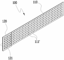
단위 난간대(100)는, 세로의 길이보다 가로의 길이가 더 긴 패널 형상의 몸체(110)의 일단부에는 폐쇄된 형상의 가이드부(120)가 형성되면서 가이드부(120)에는 몸체(110)의 단면 형상 및 크기와 동일한 안내공(121)이 형성되어 이루어진다.The
단위 난간대(100)는 패널 형상으로 구성함이 바람직하지만 경우에 따라서는 각진 봉형상, 반원형 봉 형상 등 다양하게 구성할 수 있음은 자명하다.It is preferable that the
이때, 몸체(110)의 가이드부 반대측 단부에는 상하방향으로 등간격을 이루도록 다수의 고정공(111)이 형성되어 개구부(1)의 형상, 난간대(200) 설치 위치 등의 조건에 따라 고정공(111) 중 선택하여 개구부(1)의 측면에 고정시킬 수 있도록 구성된다.At this time, a plurality of
가이드부(120)는 몸체(110)의 폭보다 큰 폭으로 이루어지면서 몸체(110)의 상부와 하부보다 더 외측으로 각각 돌출 형성되며, 안내공(121)은 몸체(110)의 길이방향과 수평을 이루도록 형성되어 2개의 단위 난간대(100)를 서로 반대방향에서 안내공(121)에 끼워 자유롭게 슬라이딩될 수 있도록 구성된다.The
이러한 단위 난간대(100) 2개가 서로 반대방향으로 배치되고, 단위 난간대(100)의 몸체(110)의 고정공측 단부가 반대측 단위 난간대(100) 가이드부(120)의 안내공(121)에 슬라이딩 가능하게 각각 끼워져 각 단위 난간대(100) 사이를 고정하지 않고 그 상태 그대로 난간대(200)를 이루게 된다.Two of the
또한, 각 단위 난간대(100)를 개구부(1)의 측면에 고정하는 앵커볼트와 같은 고정부(300)가 더 구비된다.Further, a
아울러, 개구부(1)에 다수의 난간대(200)가 고정되면 이들 사이를 수직방향으로 연결해주는 보강대(400)가 더 구비되는데, 보강대(400)는 다수의 탄성 끼움편(401)이 형성되어 이 탄성 끼움편(401)이 난간대(200)에 각각 끼워져 고정될 수 있도록 구성된다.The
이와 같이 구성된 본 고안의 바람직한 실시 예에 따른 안전 난간은 다음과 같은 작용을 한다.The safety railing according to the preferred embodiment of the present invention configured as described above has the following functions.
먼저, 단위 난간대(100) 2개를 서로 반대방향으로 배치하고, 각 단위 난간대(100)의 고정공측 단부를 반대측 단위 난간대(100)의 안내공(121)을 통과시켜 서로 끼워주면 각 단위 난간대(100)가 서로 슬라이딩 가능하게 끼워질 수 있으며, 이러한 상태 그대로 난간대(200)를 이루게 된다.First, the two
난간대(200)를 개구부(1)로 옮겨 개구부(1)의 폭이 맞게 각 단위 난간대(100)를 슬라이딩시켜 길이조정을 해주고, 각 단위 난간대(100)의 고정공(111)을 통해 앵커볼트와 같은 고정부(300)로 개구부(1)의 측면에 각각 고정시켜주면 간단하게 안전 난간의 설치가 완료된다.The
이때, 각 단위 난간대(100)의 가이드부(120) 폭은 몸체(110)의 폭보다 더 크게 형성되면서 몸체(110) 상부와 하부보다 더 외측으로 돌출 형성되어 있으므로 각 단위 난간대(100)를 옮기는 과정에서 의도치않게 각 단위 난간대(1000가 슬라이딩되거나, 각 단위 난간대(100)를 슬라이딩시켜 길이조정을 해주는 과정에서 과도하게 당기더라도 각 단위 난간대(100)의 가이드부(120)끼리 서로 접촉되어 단위 난간대(100)가 빠지지 않게 되므로 안전성을 향상시킬 수 있게 된다.The width of the
또한, 안내공(121)은 몸체(110)의 단면 형상 및 크기와 동일하게 구성되면서 몸체(110)의 길이방향과 수평방향으로 형성되어 있으므로 각 단위 난간대(100)의 고정공측 단부를 안내공(121)에 끼운 상태에서 원활하게 슬라이딩될 수 있는 것이며, 안내공(121)과 몸체(110) 사이에 틈새가 발생되지 않아 난간대(200)가 안전하게 유지될 수 있는 것이다.Since the
난간대(200)는 안전성 향상을 위해 개구부(1)에 다단으로 설치해주게 되는데, 개구부(1)에 난간대(200)를 다수개 설치한 상태에서 보강대(400)의 탄성 끼움편(401)이 각 난간대(200) 상부에 위치되도록 한 상태에서 눌러 내리면 보강대(400)가 각 난간대(200)에 끼워짐과 동시에 각 난간대(200) 사이에 수직방향으로 간편하게 고정될 수 있으며, 이와 같이 보강대(400)를 각 난간대(200) 사이에 끼워 고정시켜주면 난간대(200) 사이의 공간을 막아줄 수 있음은 물론 난간대(200)의 강성이 보강되어 안전성을 더욱 향상시킬 수 있게 된다.In order to improve safety, the
한편, 본 고안의 바람직한 실시예에서는 단위 난간대(100)의 고정공측 단부를 개구부(1)의 각 측면에 고정시켜주는 것을 예로 하였는데, 이러한 상태에서는 각 단위 난간대(100)의 접촉부위가 고정되지 않은 상태로 있게 되어 보다 안전한 구성을 가질 필요가 있다.In the preferred embodiment of the present invention, the stationary side ends of the
도 7은 본 고안의 다른 실시예에 따른 안전 난간의 단위 난간대 사시도이고, 도 8은 본 고안의 다른 실시예에 따른 안전 난간의 단위 난간대 끼움 상태 분해사시도이며, 도 9는 본 고안의 다른 실시예에 따른 안전 난간의 단위 난간대가 끼워진 상태 사시도이고, 도 10은 본 고안의 다른 실시예에 따른 안전 난간의 설치 상태도이다.FIG. 7 is a perspective view of a unit rail of a safety guardrail according to another embodiment of the present invention, FIG. 8 is an exploded perspective view of a unit rail of a safety guardrail according to another embodiment of the present invention, FIG. 10 is a perspective view of a safety guardrail according to another embodiment of the present invention. FIG. 10 is a perspective view of a safety guardrail according to another embodiment of the present invention.
본 고안의 다른 실시예에 따른 안전난간은, 도 7 내지 도 10에 도시한 바와 같이 난간대(200)를 이루는 각 단위 난간대(100) 사이에서도 고정이 이루어질 수 있도록 함으로써 보다 안전한 안전 난간을 구현하기 위한 것으로, 몸체(110)와 가이드부(120) 전체에 상하좌우 방향으로 다수의 고정공(111')이 형성되어 난간대(200)를 이루는 2개의 단위 난간대(100) 사이, 2개의 단위 난간대(100)와 개구부(1)의 각 측면에서 고정공(111')을 통해 각각 고정이 이루어지도록 구성된 것이다.As shown in FIGS. 7 to 10, the safety railing according to another embodiment of the present invention can be fixed between each
이와 같이 구성하게 되면 각 단위 난간대(100)를 반대로 배치하여 서로 슬라이딩 가능하게 끼워줌으로써 길이 조절이 가능토록 하는 것은 본 고안의 바람직한 실시예에 동일하며, 이러한 상태에서 각 단위 난간대(100) 사이를 고정볼트(301)를 통해 서로 고정해주어 난간대(200)를 이루는 2개의 단위 난간대(100)가 서로 고정될 수 있으며, 이러한 난간대(200)를 개구부(1)의 측면에 고정시킬 때에는 개구부(1) 측면의 고정위치에 해당하는 고정공(111')을 선택하여 앵커볼트와 같은 고정부(300)로 고정해주면 되는 것이다.In such a configuration, it is the same as in the preferred embodiment of the present invention that the
따라서, 각 단위 난간대(100)가 서로 고정됨에 따라 보다 안전하면서 강성이 보강된 안전 난간을 구현할 수 있음은 자명하다.Therefore, it is obvious that the safety railing can be realized more securely and stiffer as the unit rails 100 are fixed to each other.
또한, 고정공(111')이 몸체(110)와 가이드부(120) 전체에 상하좌우 방향으로 다수개 형성되어 있으므로 단위 난간대(100)의 무게가 경감되어 취급이 편리해지게 되고, 각 단위 난간대(100)의 사이, 각 단위 난간대(100)와 개구부(1)의 각 측면에 고정시켜줄 때 고정공(111')의 위치를 임의로 선택할 수 있어 작업이 편리한 이점도 있게 된다.In addition, since a plurality of fixing holes 111 'are formed on the
도면상에 설명하지는 않았지만 본 고안의 다른 실시에에서도 보강대(400)를 적용하여 다단의 난간대(200) 사이를 연결하여 강성을 보강해줄 수 있음은 자명하다.Although not illustrated in the drawings, it is apparent that the reinforcing
이상, 본 고안을 도면에 도시된 실시예를 참조하여 설명하였다. 그러나, 본 고안은 이에 한정되지 않고 본 고안이 속하는 기술분야에서 통상의 지식을 가진 자에 의해 본 고안과 균등한 범위에 속하는 다양한 변형예 또는 다른 실시예가 가능하다. The present invention has been described above with reference to the embodiments shown in the drawings. However, the present invention is not limited to this, and various modifications and other embodiments falling within the scope of the present invention can be made by those skilled in the art to which the present invention belongs.
1 : 개구부 100 : 단위 난간대
110 : 몸체 111,111' : 고정공
120 : 가이드부 121 : 안내공
200 : 난간대 300 : 고정부
301 : 고정볼트 400 : 보강대
401 : 탄성 끼움편1: opening 100: unit railing
110:
120: guide part 121: guide ball
200: railing 300:
301: Fixing bolt 400: Reinforcing bar
401: elastic fitting piece
Claims (5)
상기 단위 난간대(100) 2개가 서로 반대방향으로 배치되고, 단위 난간대(100)의 가이드부(120) 반대측 몸체(110) 단부가 반대측 단위 난간대(100)의 가이드부(120) 안내공(121)에 슬라이딩 가능하게 각각 끼워져 이루어지는 난간대(200); 및
상기 단위 난간대(100)를 개구부(1)의 측면에 고정하는 고정부(300)
일면에 다수의 탄성 끼움편(401)이 형성되어 개구부(1)에 다단으로 고정된 다수의 난간대(200)에 상기 탄성 끼움편(401)이 각각 끼워져 난간대(200) 사이를 수직방향으로 연결하는 보강대(400)를 포함하는 것을 특징으로 하는 안전 난간.
A body 110 having a longer length than a longitudinal length of the body 110 and having a width greater than the width of the body 110 in a closed form at one end of the body 110, The guide part 120 has the same shape and size as the cross section of the body 110. The guide part 120 is formed to be parallel to the longitudinal direction of the body 110 A unit balustrade 100 having a plurality of fixing holes 111 formed at an end of the body 110 opposite to the guide unit 120 so as to be equidistantly spaced apart in the vertical direction;
Two unit railing members 100 are disposed opposite to each other and the end of the unit body 110 opposite to the guide unit 120 of the unit railing member 100 is inserted into the guide hole 121 of the guide unit 120 of the opposite unitary railing member 100, (200) slidably fitted in the railing (200); And
A fixing part 300 for fixing the unit balustrade 100 to the side of the opening 1,
A plurality of resilient fitting pieces 401 are formed on one side and the elastic fitting pieces 401 are inserted into a plurality of railbands 200 fixed to the opening 1 in multiple stages so as to connect the railblocks 200 in a vertical direction And a reinforcing bar (400).
상기 몸체(110)와 가이드부(120) 전체에는 상하좌우 방향으로 단위 난간대(100)의 무게가 경갑되어 취급이 편리해지도록 다수의 고정공(111')이 형성되고, 난간대(200)를 이루는 2개의 단위 난간대(100) 사이, 상기 2개의 단위 난간대(100)와 상기 개구부(1)의 각 측면에서 상기 고정공(111')을 통해 각각 고정이 이루어지는 것을 특징으로 하는 안전 난간.
The method according to claim 1,
A plurality of fixing holes 111 'are formed on the entire body 110 and the guide 120 so that the weight of the unit rail 100 may be offset in the vertical, Is fixed between the two unit railings (100) through the fixing holes (111 ') at the respective sides of the two unit railings (100) and the opening (1).
Priority Applications (1)
| Application Number | Priority Date | Filing Date | Title |
|---|---|---|---|
| KR2020170001812U KR200485279Y1 (en) | 2017-04-11 | 2017-04-11 | Safety parapet |
Applications Claiming Priority (1)
| Application Number | Priority Date | Filing Date | Title |
|---|---|---|---|
| KR2020170001812U KR200485279Y1 (en) | 2017-04-11 | 2017-04-11 | Safety parapet |
Publications (1)
| Publication Number | Publication Date |
|---|---|
| KR200485279Y1 true KR200485279Y1 (en) | 2017-12-15 |
Family
ID=61259209
Family Applications (1)
| Application Number | Title | Priority Date | Filing Date |
|---|---|---|---|
| KR2020170001812U KR200485279Y1 (en) | 2017-04-11 | 2017-04-11 | Safety parapet |
Country Status (1)
| Country | Link |
|---|---|
| KR (1) | KR200485279Y1 (en) |
Citations (4)
| Publication number | Priority date | Publication date | Assignee | Title |
|---|---|---|---|---|
| JPH0755237Y2 (en) * | 1989-08-31 | 1995-12-20 | 好宏 与那原 | Safety handrail device for opening |
| KR200381619Y1 (en) * | 2005-01-24 | 2005-04-14 | 정윤수 | prefab safety balustrade |
| KR20140142832A (en) | 2013-06-05 | 2014-12-15 | 주식회사 한주 에이 피 에스 | Separable safety balustrade |
| KR20160002284U (en) * | 2014-12-23 | 2016-07-01 | 주식회사 더원 | Safety parapet |
-
2017
- 2017-04-11 KR KR2020170001812U patent/KR200485279Y1/en active IP Right Grant
Patent Citations (4)
| Publication number | Priority date | Publication date | Assignee | Title |
|---|---|---|---|---|
| JPH0755237Y2 (en) * | 1989-08-31 | 1995-12-20 | 好宏 与那原 | Safety handrail device for opening |
| KR200381619Y1 (en) * | 2005-01-24 | 2005-04-14 | 정윤수 | prefab safety balustrade |
| KR20140142832A (en) | 2013-06-05 | 2014-12-15 | 주식회사 한주 에이 피 에스 | Separable safety balustrade |
| KR20160002284U (en) * | 2014-12-23 | 2016-07-01 | 주식회사 더원 | Safety parapet |
Similar Documents
| Publication | Publication Date | Title |
|---|---|---|
| CN110869569B (en) | Platform for assembling elevator equipment | |
| US7140473B2 (en) | Safety top balustrade for a car of a machine room-less elevator | |
| DE102009008307A1 (en) | Parapet wall i.e. glass parapet wall for building construction, has form-fit active blocking device arranged between support profile and base profile and blocking support profile during loading of plate by lifting from base profile | |
| KR102119926B1 (en) | Cable tray | |
| KR100855758B1 (en) | Safety scaffold preventing from worker from falling when using lift of working place | |
| KR200485279Y1 (en) | Safety parapet | |
| KR20080068177A (en) | Passage for inspection of bridge | |
| KR101366483B1 (en) | Supporting device for concrete beam form | |
| KR101761056B1 (en) | Prefabricated framework scaffolding capable of extending ladder rail | |
| EP2631390A2 (en) | Lifting and securing device for a ladder scaffold and lifting and securing scaffold | |
| EP1972739A2 (en) | Extendable safety guardrail | |
| KR20160002284U (en) | Safety parapet | |
| JP6024605B2 (en) | Elevator installation work floor equipment | |
| KR101867005B1 (en) | Assembly type hand rail | |
| KR100901016B1 (en) | Safety bracket to external wall scaffolding for a structure | |
| US9540215B2 (en) | Method for installing an elevator car sling | |
| KR100680277B1 (en) | Ladder's bracket for H-beam | |
| ITUB20150688A1 (en) | Guide device for temporary scaffolding barriers | |
| KR100996117B1 (en) | Safety door footing for industrial elevator | |
| KR20010001357U (en) | Safety work bench for elevator setup | |
| KR101459343B1 (en) | The wire fixing braket for a belay | |
| KR950006148A (en) | Mobile club for concrete slab of steel bridge | |
| KR20240014329A (en) | Fall prevention lock fastening ladder with pole step bolt hanging structure | |
| IT202100025505A1 (en) | RAMPING BRACKET STRUCTURE FOR FORMWORKS FOR VERTICAL CASTINGS | |
| KR101594986B1 (en) | foothold panel |
Legal Events
| Date | Code | Title | Description |
|---|---|---|---|
| E701 | Decision to grant or registration of patent right | ||
| REGI | Registration of establishment |