KR200482711Y1 - A gas sealing test device for a bundle tube - Google Patents
A gas sealing test device for a bundle tube Download PDFInfo
- Publication number
- KR200482711Y1 KR200482711Y1 KR2020140009412U KR20140009412U KR200482711Y1 KR 200482711 Y1 KR200482711 Y1 KR 200482711Y1 KR 2020140009412 U KR2020140009412 U KR 2020140009412U KR 20140009412 U KR20140009412 U KR 20140009412U KR 200482711 Y1 KR200482711 Y1 KR 200482711Y1
- Authority
- KR
- South Korea
- Prior art keywords
- bundle
- gas
- tube
- gas supply
- housing
- Prior art date
Links
Images


Classifications
-
- G—PHYSICS
- G01—MEASURING; TESTING
- G01M—TESTING STATIC OR DYNAMIC BALANCE OF MACHINES OR STRUCTURES; TESTING OF STRUCTURES OR APPARATUS, NOT OTHERWISE PROVIDED FOR
- G01M3/00—Investigating fluid-tightness of structures
- G01M3/02—Investigating fluid-tightness of structures by using fluid or vacuum
- G01M3/26—Investigating fluid-tightness of structures by using fluid or vacuum by measuring rate of loss or gain of fluid, e.g. by pressure-responsive devices, by flow detectors
- G01M3/28—Investigating fluid-tightness of structures by using fluid or vacuum by measuring rate of loss or gain of fluid, e.g. by pressure-responsive devices, by flow detectors for pipes, cables or tubes; for pipe joints or seals; for valves ; for welds
-
- F—MECHANICAL ENGINEERING; LIGHTING; HEATING; WEAPONS; BLASTING
- F28—HEAT EXCHANGE IN GENERAL
- F28F—DETAILS OF HEAT-EXCHANGE AND HEAT-TRANSFER APPARATUS, OF GENERAL APPLICATION
- F28F1/00—Tubular elements; Assemblies of tubular elements
-
- G—PHYSICS
- G01—MEASURING; TESTING
- G01M—TESTING STATIC OR DYNAMIC BALANCE OF MACHINES OR STRUCTURES; TESTING OF STRUCTURES OR APPARATUS, NOT OTHERWISE PROVIDED FOR
- G01M3/00—Investigating fluid-tightness of structures
- G01M3/02—Investigating fluid-tightness of structures by using fluid or vacuum
- G01M3/26—Investigating fluid-tightness of structures by using fluid or vacuum by measuring rate of loss or gain of fluid, e.g. by pressure-responsive devices, by flow detectors
- G01M3/28—Investigating fluid-tightness of structures by using fluid or vacuum by measuring rate of loss or gain of fluid, e.g. by pressure-responsive devices, by flow detectors for pipes, cables or tubes; for pipe joints or seals; for valves ; for welds
- G01M3/2807—Investigating fluid-tightness of structures by using fluid or vacuum by measuring rate of loss or gain of fluid, e.g. by pressure-responsive devices, by flow detectors for pipes, cables or tubes; for pipe joints or seals; for valves ; for welds for pipes
Abstract
튜브시트의 직경이 다른 번들튜브들의 리크(leak)를 한 장치에서 검사를 가능하게 한 가스히터용 열교환 번들튜브의 기밀 시험장치에 관한 것이다.
본 고안 기밀 시험장치는 롤러(100)에 의해서 장치의 이송을 간편하게 하며, 크기가 다른 번들튜브들을 선택적으로 한 장비에서 행할 수 있게 함으로써 보관이 용이하고 비용을 절감할 수 있게 한다. 또한, 시험 대상인 번들튜브(70)(80)를 하우징(10) 내에 장착하여 기밀시험을 하게 되므로 고압의 에어에 따른 안전사고를 예방할 수 있게 한다.To a hermetically sealed tester for a heat exchanger bundle tube for a gas heater that allows inspection of a leak of bundle tubes of different tube sheet diameters.
The present design of the airtightness testing device simplifies the transfer of the device by means of the rollers 100 and enables bundles of different sizes to be selectively carried out in one device, thereby facilitating storage and reducing costs. In addition, since the bundle tubes 70 and 80 to be tested are mounted in the housing 10 to perform the airtightness test, it is possible to prevent safety accidents due to high-pressure air.

Description
본 고안은 가스히터용 열교환 번들튜브의 기밀 시험장치에 관한 것으로, 더 상세하게는 튜브시트의 직경이 다른 번들튜브들의 리크(leak)를 한 장치에서 검사를 가능하게 한 가스히터용 열교환 번들튜브의 기밀 시험장치에 관한 것이다.The present invention relates to a gas-tightness testing apparatus for a heat-exchanging bundle tube for a gas heater, and more particularly, to a gas-tightness testing apparatus for a heat-exchanging bundle tube for a gas heater that enables inspection in a leak- And to an airtightness testing apparatus.
천연가스는 해외 원산지에서 채취되어 액체상태(LNG)로 국내에 도입되며, 이를 다시 기화하여 발전소 등에 직접 공급하거나 도시가스회사를 통해 일반 가정 및 사무실 등에 공급하고 있다.Natural gas is taken from foreign countries and introduced into the country as a liquid state (LNG). It is supplied to power plants directly by vaporizing it, or is supplied to general households and offices through a city gas company.
한편, 천연가스를 수요처로 공급하기 위해 생산기지에서 공급관리소로 공급되는 천연가스는 고압(10~70㎏/㎠)이므로 수요처로 연결된 배관을 통해 공급하기 전에 압력조절밸브(PCV ; Pressure control valve)를 통해 적절한 압력으로 감압하여 공급하게 되는데, 감압과정에서 천연가스의 온도가 1㎏/㎠ 감압 시 마다 약 0.56℃ 온도강하가 발생하므로 압력조절밸브 등 배관라인의 기능이 저하될 가능성이 내재되어 안전 및 안정 운영이 원활하게 이루어지지 않을 수 있다.On the other hand, since natural gas supplied from the production base to the supply station is high pressure (10 ~ 70㎏ / ㎠) in order to supply natural gas to consumers, pressure control valve (PCV) The temperature drop of the natural gas is about 0.56 ℃ per 1 kg / ㎠ of decompression. Therefore, there is a possibility that the function of the piping line such as the pressure control valve may be degraded. And stable operation may not be performed smoothly.
따라서, 상기 압력조절밸브로 천연가스를 공급하기 전에 감압과정에서 냉각으로 인한 결빙이 발생하지 않을 정도의 온도로 미리 예열해 주게 되는데, 천연가스의 예열은 가스히터 본체에서 가스를 연료로 버너를 이용하여 물을 가열하고 가열된 온수 속으로 가스히터 번들튜브(bundle tube)를 침조시켜 가스히터 번들튜브 내부로 흐르는 가스를 승온시키는 간접가열 방식을 사용한다.Therefore, before the natural gas is supplied to the pressure regulating valve, it is preheated to a temperature at which freezing due to cooling does not occur during the decompression process. Preheating of the natural gas is performed by using a burner An indirect heating method is used in which water is heated and a gas heater bundle tube is poured into heated hot water to raise the temperature of the gas flowing into the gas heater bundle tube.
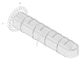
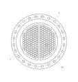
상기 번들튜브는 도 1 및 도 2에 도시된 바와 같이, 다수의 U자형 튜브(1)들이 다발을 이루어 튜브시트(2)에 용접된 것으로 다수의 튜브(1)를 이용함으로써 번들튜브를 통과하는 유체와 외부와의 열교환 면적을 증가시켜 보다 효율적인 열교환 작용이 이루어지도록 구성된 것이다.1 and 2, a plurality of
따라서, 튜브시트(2)의 정면에는 상기 번들튜브(1)들의 양쪽 단부가 튜브시트의 원판면을 반분한 구역에 각각 밀집배치되어 입구와 출구로서 작용하도록 되어 있다. 또한 튜브시트(2)의 외측 플랜지 부분에는 일정 간격으로 볼트체결공(2a)이 형성되어 튜브시트(2)와 온수 순환라인을 연결해 주는 헤더(header;도 3참조)가 결합될 수 있도록 되어 있다.Accordingly, on the front surface of the
한편, 상기와 같은 구조의 튜브번들은 단순한 밴딩 파이프인 튜브(1) 자체에는 거의 결함이 발생하지 않고, 주로 튜브(1)와 튜브시트(2)의 사이에 용접불량이나 제작 및 운반시의 충격에 의해 크랙이 발생하여 이를 통해 가스의 누설이 발생하게 된다.On the other hand, the tube bundle having the above-described structure has almost no defects in the
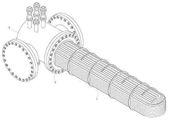
따라서, 튜브번들의 건전성 검사를 통해 누설이 발생하는 지점을 찾아 보강용접하여 보수하게 된다. 종래의 튜브번들 건전성 검사는 도 3에 도시된 바와 같이, 육안검사, 침투탐상검사(이하, PT검사라 칭한다; 모세관 현상을 이용한 표면 결함 검사법으로서, 표면세척→침투액 도포→표면세척→현상액 도포→현상의 단계로 이루어진다. 검사대상물의 표면에 결함이 있을 경우 침투액이 그 결함부위로 침투하게 되고, 침투된 침투액이 현상액에 의해 흡출되어 현상액 도포 표면에 다른 색깔로 표출됨으로써 결함부위의 검출이 용이하다.)를 통해 누수부위를 찾아내고 용접보수 한 뒤, 다시 보수부위만을 PT검사하여 보수여부를 확인하고, 최종적으로 튜브번들에 헤더를 부착하고 질소를 소정압으로 주입/유지하여 질소압력의 변화를 통해 튜브번들의 기밀 상태를 최종 점검하고 있다.Therefore, through the integrity inspection of the tube bundle, the point where leakage occurs is found and reinforced to repair it. As shown in FIG. 3, the conventional tube bundle integrity test includes a visual inspection, a penetration test (hereinafter referred to as PT inspection), a surface defect inspection using capillary phenomenon, a surface cleaning, a permeation application, a surface cleaning, When the surface of the object to be inspected is defective, the penetrating liquid penetrates into the defective portion, and the penetrated penetrating liquid is sucked out by the developing liquid and is displayed in a different color on the surface of the developer applying portion, . After confirming the repair of the repair area, it is confirmed whether the water is repaired. Finally, the header is attached to the tube bundle, and nitrogen is injected / maintained at a predetermined pressure to change the nitrogen pressure The tube bundle is undergoing a final check for airtightness.
상기와 같이 질소를 사용한 기밀 및 내압시험에서 압력저하가 발생하면 여전히 결함부위가 존재하는 것으로 판단하고, 상기 과정을 반복 실시하였다.In the airtightness and pressure resistance test using nitrogen as described above, it was determined that a defective portion still existed when the pressure drop occurred, and the above procedure was repeated.
그런데, 가스히터의 열교환 용량에 따라 번들튜브(1) 및 튜브시트(2)의 크기가 다르게 되는데, 이들을 검사하기 위하여는 튜브시트(2)의 직경크기에 맞는 검사장비가 별도로 요구되는 문제점이 있다.However, the sizes of the
본 고안은 상기와 같은 문제점을 해결하기 위하여 창출된 것으로써, 크기가 다른 번들튜브를 하나의 장비에 의해 리크시험을 할 수 있도록 한 가스히터용 열교환 번들튜브의 기밀 시험장치를 제공하는 데 그 목적이 있다.The present invention has been made to solve the above-mentioned problems, and it is an object of the present invention to provide a gas-tightness testing apparatus for a heat-exchange bundle tube for a gas heater, which can perform a leak test on a bundle tube of a different size .
상기 목적을 달성하는 본 고안은 선단에 튜브시트가 형성된 크기가 다른 제1,2번들튜브의 기밀유지를 시험하기 위한 가스히터용 열교환 번들튜브의 기밀 시험장치에 있어서,The present invention for achieving the above object is to provide an airtightness testing apparatus for a heat exchange bundle tube for a gas heater for testing the airtightness of first and second bundle tubes having different sizes,
양단부가 개구되고 측면에 상기 번들튜브를 출입시키기 위한 출입구가 형성된 하우징과,A housing having openings at both ends thereof and having a doorway for opening and closing the bundle tube,
상기 하우징의 일측 개구에 결합되며 상기 제1 번들튜브의 튜브시트가 결합되는 제1가스공급헤드와,A first gas supply head coupled to one side opening of the housing and coupled to the tube sheet of the first bundle tube,
상기 하우징의 타측 개구에 결합되며 상기 제2 번들튜브의 튜브시트가 결합되는 제2가스공급헤드와,A second gas supply head coupled to the other opening of the housing and coupled to the tube sheet of the second bundle tube,
상기 제1가스공급헤드와 연결되며 제1밸브가 마련된 제1가스공급라인과,A first gas supply line connected to the first gas supply head and provided with a first valve,
상기 제2가스공급헤드와 연결되며 제2밸브가 마련된 제2가스공급라인과,A second gas supply line connected to the second gas supply head and having a second valve,
상기 제1,2밸브 사이에 연결되어 상기 제1,2가스공급라인에 가스를 공급하는 가스공급기와,A gas supplier connected between the first and second valves for supplying gas to the first and second gas supply lines,
상기 제1,2밸브 사이에 연결되어 상기 제1,2번들튜브내의 가스 압력변화를 기록하는 압력레코드를 구비하여서,And a pressure record coupled between the first and second valves for recording gas pressure changes in the first and second bundle tubes,
상기 하우징에 상기 제1,2번들튜브를 선택적으로 결합시키고, 상기 제1,2밸브를 선택적으로 개방하여서 제1,2 번들튜브를 선택적으로 기밀 시험할 수 있도록 된 것을 특징으로 한다.The first and second bundle tubes are selectively coupled to the housing, and the first and second valves are selectively opened to selectively perform the airtightness test on the first and second bundle tubes.
또한, 본 고안 시험장치는 상기 하우징의 바닥면에 이동을 위한 복수의 롤러가 결합된 것을 특징으로 한다.In addition, the present invention is characterized in that a plurality of rollers for moving are coupled to the bottom surface of the housing.
첫째, 본 고안 기밀 시험장치는 롤러(100)에 의해서 장치의 이송을 간편하게 하며, 크기가 다른 번들튜브들을 선택적으로 한 장비에서 행할 수 있게 함으로써 보관이 용이하고 비용을 절감할 수 있게 한다.First, the present invention airtightness testing apparatus simplifies the transfer of the apparatus by the
둘째, 시험 대상인 번들튜브(70)(80)를 하우징(10) 내에 장착하여 기밀시험을 하게 되므로 고압의 에어에 따른 안전사고를 예방할 수 있게 한다.Second, since the
도 1은 통상의 번들튜브를 나타탠 사시도,
도 2는 도 1의 측면도,
도 3은 도 1에 헤더가 부착한 상태의 사시도,
도 4는 본 고안 실시예 시험장치의 개략도,
도 5는 본 고안 시험장치의 개략 측면도,
도 6은 도 5의 측면도이다.1 is a perspective view of a conventional bundle tube,
Fig. 2 is a side view of Fig. 1,
Fig. 3 is a perspective view of a state in which a header is attached to Fig. 1,
4 is a schematic view of the test apparatus of the present embodiment;
5 is a schematic side view of the present design test apparatus,
Fig. 6 is a side view of Fig. 5. Fig.
본 고안 실시예의 가스히터용 열교환 번들튜브의 기밀 시험장치는 튜브시트의 직경이 다른 번들튜브들의 리크(leak)를 한 장치에서 검사를 가능하게 한다.The airtightness testing apparatus of the heat exchanger bundle tube for a gas heater of the present invention enables testing in a device that leaked bundle tubes having different tube sheet diameters.
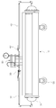
본 고안 실시예의 기밀 시험장치를 나타낸 도 4 내지 도 6을 참조하면, 이는 양단부가 개구되고 측면에 선단에 튜브시트가 형성된 크기가 다른 제1,2 번들튜브(70)(80)들을 출입시키기 위한 출입구(11)가 형성된 하우징(10)과, 상기 하우징(10)의 일측 개구에 결합되며 상기 제1 번들튜브(70)의 튜브시트가 결합되는 제1가스공급헤드(31)와, 상기 하우징(10)의 타측 개구에 결합되며 상기 제2 번들튜브(80)의 튜브시트가 결합되는 제2가스공급헤드(41)와, 상기 제1가스공급헤드(31)와 연결되며 제1밸브(33)가 마련된 제1가스공급라인(32)과, 상기 제2가스공급헤드(41)와 연결되며 제2밸브(43)가 마련된 제2가스공급라인(42)과, 상기 제1,2밸브(33)(43) 사이에 연결되어 상기 제1,2가스공급라인(32)(42)에 가스를 공급하는 가스공급기(50)와, 상기 제1,2밸브(33)(43) 사이에 연결되어 상기 제1,2 번들튜브(70)(80)내의 가스 압력변화를 기록하는 압력레코드(60)를 구비한다.Referring to FIGS. 4 to 6 showing the airtightness testing apparatus of the present embodiment, the first and
상기 제1,2 번들튜브(70)(80)의 구조는 도 1의 구조와 동일하므로 상세한 설명은 생략하기로 한다.The structure of the first and
상기와 같은 구성의 기밀 시험장치는 시험하고자 하는 제1 번들튜브(70)를 하우징(10)에 진입시켜서 제1가스공급헤드(31)의 플랜지(31a)에 튜브시트를 맞대어 볼트체결공(31b)을 통하여 볼트체결한다.The airtightness testing apparatus having the above-described configuration is configured such that the
이어서 제2밸브(43)를 차단하고 제1밸브(33)를 개방한 후 가스공급기(50)를 통하여 가스를 일정시간 동안 제1 번들튜브(70)에 공급하면서, 압력레코드(60)를 통허여 제1 번들튜브(70) 내의 압력변화를 기록한다.Then, the
상기 압력레코드(60)의 압력저하가 기록되게 되면 제1 번들튜브(70)에서의 가스 리크가 발생하는 것으로 판단하고, 제1 번들튜브(70)에 검사액을 분사하여 버블 발생부분을 찾아내어 리크 발생부분을 용접등의 수리를 행한다.It is determined that gas leakage occurs in the
한편, 제1 번들튜브(70)와 크기가 다른 제2 번들튜브(80)의 기밀 시험을 위해서는 제1 번들튜브(70)를 하우징(10)으로부터 분리해내고, 제2 번들튜브(80)를 상기와 같이 하우징(10)에 결합하여 기밀 시험을 행한다.Meanwhile, for the airtightness test of the
상기와 같은 기밀 시험장치는 롤러(100)에 의해서 장치의 이송을 간편하게 하며, 크기가 다른 번들튜브들을 선택적으로 한 장비에서 행 할 수 있게 함으로써 보관이 용이하고 비용을 절감할 수 있게 한다.The airtightness testing apparatus as described above facilitates the conveyance of the apparatus by the
또한, 시험 대상인 번들튜브(70)(80)를 하우징(10) 내에 장착하여 기밀시험을 하게 되므로 고압의 에어에 따른 안전사고를 예방할 수 있게 한다.In addition, since the
10...하우징 11...출입구
31,41...제1,2가스공급헤드 60...압력레코드
70,80...제1,2 번들튜브10
31, 41 ... First and second
70, 80 ... First and second bundle tubes
Claims (2)
양단부가 개구되고 측면에 상기 제1,2 번들튜브(70)(80)들을 출입시키기 위한 출입구(11)가 형성된 하우징(10)과,
상기 하우징(10)의 일측 개구에 결합되며 상기 제1 번들튜브(70)의 튜브시트가 결합되는 제1가스공급헤드(31)와,
상기 하우징(10)의 타측 개구에 결합되며 상기 제2 번들튜브(80)의 튜브시트가 결합되는 제2가스공급헤드(41)와,
상기 제1가스공급헤드(31)와 연결되며 제1밸브(33)가 마련된 제1가스공급라인(32)과,
상기 제2가스공급헤드(41)와 연결되며 제2밸브(43)가 마련된 제2가스공급라인(42)과,
상기 제1,2밸브(33)(43) 사이에 연결되어 상기 제1,2가스공급라인(32)(42)에 가스를 공급하는 가스공급기(50)와,
상기 제1,2밸브(33)(43) 사이에 연결되어 상기 제1,2 번들튜브(70)(80)내의 가스 압력변화를 기록하는 압력레코드(60)를 구비하여서,
상기 하우징(10)에 상기 제1,2 번들튜브(70)(80)를 선택적으로 결합시키고, 상기 제1,2밸브(33)(43)를 선택적으로 개방하여서 제1,2 번들튜브(70)(80)를 선택적으로 기밀 시험할 수 있도록 된 것을 특징으로 하는 가스히터용 열교환 번들튜브의 기밀 시험장치.
A gas-tightness testing apparatus for a heat-exchange bundle tube for a gas heater for testing the air-tightness maintenance of first and second bundle tubes of different sizes,
A housing 10 having openings at both ends thereof and having an entrance 11 for allowing the first and second bundle tubes 70 and 80 to enter and exit the side,
A first gas supply head 31 coupled to one side opening of the housing 10 and coupled to the tube sheet of the first bundle tube 70,
A second gas supply head 41 coupled to the other opening of the housing 10 and coupled to the tube sheet of the second bundle tube 80,
A first gas supply line 32 connected to the first gas supply head 31 and provided with a first valve 33,
A second gas supply line 42 connected to the second gas supply head 41 and provided with a second valve 43,
A gas supplier 50 connected between the first and second valves 33 and 43 to supply gas to the first and second gas supply lines 32 and 42,
And a pressure record (60) connected between the first and second valves (33, 43) to record gas pressure changes in the first and second bundle tubes (70, 80)
The first and second bundle tubes 70 and 80 are selectively coupled to the housing 10 and the first and second valves 33 and 43 are selectively opened to connect the first and second bundle tubes 70 and 70 (80) to be tested for airtightness. ≪ Desc / Clms Page number 24 >
Priority Applications (1)
| Application Number | Priority Date | Filing Date | Title |
|---|---|---|---|
| KR2020140009412U KR200482711Y1 (en) | 2014-12-19 | 2014-12-19 | A gas sealing test device for a bundle tube |
Applications Claiming Priority (1)
| Application Number | Priority Date | Filing Date | Title |
|---|---|---|---|
| KR2020140009412U KR200482711Y1 (en) | 2014-12-19 | 2014-12-19 | A gas sealing test device for a bundle tube |
Publications (2)
| Publication Number | Publication Date |
|---|---|
| KR20160002243U KR20160002243U (en) | 2016-06-29 |
| KR200482711Y1 true KR200482711Y1 (en) | 2017-02-24 |
Family
ID=56344834
Family Applications (1)
| Application Number | Title | Priority Date | Filing Date |
|---|---|---|---|
| KR2020140009412U KR200482711Y1 (en) | 2014-12-19 | 2014-12-19 | A gas sealing test device for a bundle tube |
Country Status (1)
| Country | Link |
|---|---|
| KR (1) | KR200482711Y1 (en) |
Families Citing this family (2)
| Publication number | Priority date | Publication date | Assignee | Title |
|---|---|---|---|---|
| CN106441725B (en) * | 2016-10-11 | 2019-02-05 | 北京航空航天大学 | One kind being used for micro- diameter thin-wall tube square heat exchanger high pressure air-tightness detection tool equipment |
| CN106525341B (en) * | 2016-10-11 | 2018-12-18 | 北京航空航天大学 | A kind of high pressure gas detection connector for the micro- diameter thin-wall tube of heat exchanger |
Family Cites Families (2)
| Publication number | Priority date | Publication date | Assignee | Title |
|---|---|---|---|---|
| JPH075391Y2 (en) * | 1989-09-29 | 1995-02-08 | 出光エンジニアリング株式会社 | Tube bundle tester for heat exchanger |
| KR200465212Y1 (en) | 2010-08-18 | 2013-02-07 | 주식회사 한국가스기술공사 | Tester is secret existence of bundle tube |
-
2014
- 2014-12-19 KR KR2020140009412U patent/KR200482711Y1/en active IP Right Grant
Also Published As
| Publication number | Publication date |
|---|---|
| KR20160002243U (en) | 2016-06-29 |
Similar Documents
| Publication | Publication Date | Title |
|---|---|---|
| US8291748B2 (en) | Heat exchanger leak testing method and apparatus | |
| US7454956B1 (en) | Heat exchanger leak detection using mass gas flow metering | |
| KR200482711Y1 (en) | A gas sealing test device for a bundle tube | |
| JP7084155B2 (en) | Tube leak detection device and tube leak detection method | |
| CN107860785A (en) | A kind of quick thermal fatigue test method of engine cylinder cap and device | |
| CN206300758U (en) | One kind tube bank pressure test leak-detecting device | |
| KR100869896B1 (en) | Integrity test method of tube bundle in gas heater | |
| CN101217010B (en) | An experimental device for welding recondition on tubes in service | |
| CN205301092U (en) | Raise nose above water to breathe to hold tube sheet to be float head heat -exchanger shell side pressure testing frock of flange joint formula | |
| CN104897860A (en) | Novel expanding connection technology and assessment method | |
| CN104501855A (en) | Sample device and method for testing tube-plugging effect of heat-transferring tube of vapor generator | |
| KR101456463B1 (en) | Defect inspection device for tube of heat exchanger | |
| CN106566902A (en) | Blast-furnace cooling equipment leakage detecting device | |
| CN207263384U (en) | A kind of mounting structure of test fixture and floating head heat exchanger | |
| CN107576576A (en) | A kind of experimental system that the tubular specimen of supercritical water is connected with to inside and is loaded | |
| CN201607865U (en) | Device for evaluating welding procedure and training and testing of weldors on line | |
| KR101947309B1 (en) | Gas cooler Modification method | |
| KR102195138B1 (en) | Thermal fatigue crack generator for large pipe | |
| CN211231948U (en) | Natural gas line sealing connection structure | |
| CN207318019U (en) | It is a kind of to fill ammonia device for pressure vessel and equipment ammonia infiltration leak test | |
| CN206724485U (en) | A kind of electrical heating core and firing equipment | |
| CN207779629U (en) | High Temperature Simulation device | |
| CN101280871A (en) | Large-sized calandria type fixed bed reactor high temperature molten salt leaky pipe head restoring method | |
| JP2739891B2 (en) | Inspection method of cooling groove of combustor by radiation thermometer | |
| CN102879155A (en) | Online leakage detection method and device for non-oxidation furnace radiant tube containing shielding hydrogen gas |
Legal Events
| Date | Code | Title | Description |
|---|---|---|---|
| A201 | Request for examination | ||
| E902 | Notification of reason for refusal | ||
| E701 | Decision to grant or registration of patent right | ||
| REGI | Registration of establishment | ||
| FPAY | Annual fee payment |
Payment date: 20200203 Year of fee payment: 4 |