KR200466917Y1 - Fixing device - Google Patents
Fixing device Download PDFInfo
- Publication number
- KR200466917Y1 KR200466917Y1 KR2020130000977U KR20130000977U KR200466917Y1 KR 200466917 Y1 KR200466917 Y1 KR 200466917Y1 KR 2020130000977 U KR2020130000977 U KR 2020130000977U KR 20130000977 U KR20130000977 U KR 20130000977U KR 200466917 Y1 KR200466917 Y1 KR 200466917Y1
- Authority
- KR
- South Korea
- Prior art keywords
- magnetic
- string portion
- string
- fixing
- holder
- Prior art date
Links
Images


Classifications
-
- B—PERFORMING OPERATIONS; TRANSPORTING
- B65—CONVEYING; PACKING; STORING; HANDLING THIN OR FILAMENTARY MATERIAL
- B65D—CONTAINERS FOR STORAGE OR TRANSPORT OF ARTICLES OR MATERIALS, e.g. BAGS, BARRELS, BOTTLES, BOXES, CANS, CARTONS, CRATES, DRUMS, JARS, TANKS, HOPPERS, FORWARDING CONTAINERS; ACCESSORIES, CLOSURES, OR FITTINGS THEREFOR; PACKAGING ELEMENTS; PACKAGES
- B65D63/00—Flexible elongated elements, e.g. straps, for bundling or supporting articles
- B65D63/10—Non-metallic straps, tapes, or bands; Filamentary elements, e.g. strings, threads or wires; Joints between ends thereof
-
- B—PERFORMING OPERATIONS; TRANSPORTING
- B42—BOOKBINDING; ALBUMS; FILES; SPECIAL PRINTED MATTER
- B42F—SHEETS TEMPORARILY ATTACHED TOGETHER; FILING APPLIANCES; FILE CARDS; INDEXING
- B42F1/00—Sheets temporarily attached together without perforating; Means therefor
- B42F1/02—Paper-clips or like fasteners
- B42F1/04—Paper-clips or like fasteners metallic
-
- B—PERFORMING OPERATIONS; TRANSPORTING
- B42—BOOKBINDING; ALBUMS; FILES; SPECIAL PRINTED MATTER
- B42F—SHEETS TEMPORARILY ATTACHED TOGETHER; FILING APPLIANCES; FILE CARDS; INDEXING
- B42F1/00—Sheets temporarily attached together without perforating; Means therefor
- B42F1/02—Paper-clips or like fasteners
- B42F1/10—Paper-clips or like fasteners non-metallic
-
- B—PERFORMING OPERATIONS; TRANSPORTING
- B65—CONVEYING; PACKING; STORING; HANDLING THIN OR FILAMENTARY MATERIAL
- B65D—CONTAINERS FOR STORAGE OR TRANSPORT OF ARTICLES OR MATERIALS, e.g. BAGS, BARRELS, BOTTLES, BOXES, CANS, CARTONS, CRATES, DRUMS, JARS, TANKS, HOPPERS, FORWARDING CONTAINERS; ACCESSORIES, CLOSURES, OR FITTINGS THEREFOR; PACKAGING ELEMENTS; PACKAGES
- B65D2313/00—Connecting or fastening means
- B65D2313/04—Connecting or fastening means of magnetic type
-
- B—PERFORMING OPERATIONS; TRANSPORTING
- B65—CONVEYING; PACKING; STORING; HANDLING THIN OR FILAMENTARY MATERIAL
- B65D—CONTAINERS FOR STORAGE OR TRANSPORT OF ARTICLES OR MATERIALS, e.g. BAGS, BARRELS, BOTTLES, BOXES, CANS, CARTONS, CRATES, DRUMS, JARS, TANKS, HOPPERS, FORWARDING CONTAINERS; ACCESSORIES, CLOSURES, OR FITTINGS THEREFOR; PACKAGING ELEMENTS; PACKAGES
- B65D2563/00—Flexible elongated elements, e.g. straps for bundling or supporting atricles
- B65D2563/10—Non-metallic straps, tapes or bands; Filamentary elements, e.g. strings, threads, wires; Joints between ends thereof
- B65D2563/101—Details of non-metallic straps, tapes or bands
- B65D2563/107—Details of non-metallic straps, tapes or bands having a release mechanism, e.g. reusable bundling straps
Landscapes
- Engineering & Computer Science (AREA)
- Mechanical Engineering (AREA)
- Purses, Travelling Bags, Baskets, Or Suitcases (AREA)
- Package Frames And Binding Bands (AREA)
- Sheet Holders (AREA)
Abstract
본 고안은 적어도 둘의 자성체; 상기 자성체를 각각 수용하는 적어도 둘의 고정부;및 유연한 소재로 구성되어 적어도 둘의 상기 고정부와 각각 연결되는 끈부를 포함하는 고정용 도구를 제공하여, 액세서리, 사무용 문구, 지류(紙類) 또는 케이블 등과 같은 다양한 물건을 효과적으로 묶거나 고정할 수 있는 유리한 효과를 제공한다.The present invention is directed to a magnetic device comprising at least two magnetic bodies; A fixing tool comprising at least two fixing portions each of which accommodates the magnetic body and a cord portion composed of a flexible material and connected to at least two of the fixing portions, Cables, and the like.
Description
본 고안은 고정용 도구에 관한 것으로, 더욱 상세하게는, 자성체의 자력을 이용하여 대상물을 묶거나 고정하는데 사용되는 고정용 도구에 관한 것이다.
The present invention relates to a fixing tool, and more particularly, to a fixing tool used for binding or fixing an object using a magnetic force of a magnetic body.
액세서리, 사무용 문구, 지류(紙類) 또는 케이블 등을 묶거나 고정하기 위해 통상적으로 밴드 타입 또는 끈 타입의 고정용 도구 등이 사용될 수 있다. 케이블을 묶는데 있어서, 대한민국 공개특허공보 10-2005-0008638에서 당김 해제식 접착 테이프 제품을 개시하고 있다. 당김 해제식 접착 테이프 제품은 묶음 스트랩을 포함하는데, 묶음 스트랩은 폐쇄 루프를 형성하도록 띠 형태로 구성된다. 또한 부착 부분과 정합 표면에 의해 묶음 물건이 고정되도록 구성된다. 그러나 이러한 구성은 케이블 등과 같은 선재를 묶는 용도에 한정될 가능성이 크며, 묶는 작업에 비해 묶음을 푸는 작업이 번거로울 수 있다.A band type or string type fixing tool or the like may be used for tying or fixing accessories, office stationery, paper or cables, and the like. Korean Unexamined Patent Application Publication No. 10-2005-0008638 discloses a pulling-off adhesive tape product for bundling cables. The pull-off adhesive tape product includes a bundle strap, the bundle strap being configured in a band shape to form a closed loop. And the bundle is fixed by the attachment portion and the mating surface. However, such a configuration is likely to be limited to the use of bundling a wire such as a cable, and it may be cumbersome to untie a bundle as compared to bundling.
또한, 서류와 같은 지류(紙類)를 고정하는데 있어서, 대한민국 공개특허공보 10-2012-0014275에서 서류 고정용 클립을 개시하고 있다. 서류 고정용 클립은 수용된 서류를 탄성력으로 가압하는 탄성 가압편을 포함한다. 그러나 이러한 구성 또한 소정의 서류를 고정하는 용도에 한정될 수 밖에 없다.
Further, Korean Patent Publication No. 10-2012-0014275 discloses a paper clip for fixing a paper such as a paper. The document fixing clip includes an elastic pressing piece for pressing the accommodated document with an elastic force. However, such a configuration is also limited to the use for fixing a predetermined document.
이에, 본 고안은 상기한 문제점을 해결하기 위한 것으로, 액세서리, 사무용 문구, 지류(紙類) 또는 케이블 등과 같은 다양한 물건을 효과적으로 묶거나 고정할 수 있는 정리용 도구를 제공하는 것을 그 목적으로 한다.
Accordingly, the present invention has been made to solve the above problems, and it is an object of the present invention to provide a sorting tool that can effectively bind or fix various articles such as an accessory, an office stationery, a paper or a cable.
상기 목적을 달성하기 위한 본 고안은, 적어도 둘의 자성체와, 상기 자성체를 각각 수용하는 적어도 둘의 고정부 및, 유연한 소재로 구성되어 적어도 둘의 상기 고정부와 각각 연결되는 끈부를 포함하는 고정용 도구를 제공할 수 있다.In order to achieve the above object, the present invention provides a fixing device comprising at least two magnetic bodies, at least two fixing portions for respectively receiving the magnetic bodies, and a string portion composed of a flexible material and connected to at least two of the fixing portions, Tool.
바람직하게는, 상기 끈부 및 적어도 둘의 상기 고정부는 유연한 소재로 일체로 성형될 수 있다.Preferably, the string portion and at least two of the fixed portions may be integrally formed of a flexible material.
바람직하게는, 상기 자성체는 코인형으로 구성되고, 상기 고정부는 코인형으로 구성되는 상기 자성체의 전면, 후면 및 측면 중 적어도 둘을 둘러싸서 탄성적으로 고정할 수 있다.Preferably, the magnetic body is formed in a coin-like shape, and the fixing portion can elastically surround at least two of the front surface, the rear surface, and the side surface of the magnetic body formed in a coin shape.
바람직하게는, 상기 고정부는, 상기 자성체를 수용하는 수용공간이 형성된 홀더와, 상기 끈부에서 연장 형성되어 상기 홀더가 탄성 결합하는 홀더 수용부를 포함할 수 있다.Preferably, the fixing portion may include a holder having a receiving space for accommodating the magnetic body, and a holder accommodating portion extending from the rod portion and elastically coupling the holder.
바람직하게는, 상기 홀더는 둘레면이 경사지게 형성된 걸림부와 상기 걸림부에 단차지게 결합하는 원통형 몸체를 포함할 수 있다.Preferably, the holder may include a latching portion having a circumferential surface inclined and a cylindrical body steppedly engaged with the latching portion.
바람직하게는, 상기 자성체는 2개가 마련되고, 상기 끈부의 양단에는 2개의 상기 자성체를 각각 수용하는 2개의 상기 고정부가 각각 형성될 수 있다.Preferably, two magnetic bodies are provided, and at both ends of the string portion, two fixing portions each accommodating the two magnetic bodies may be respectively formed.
바람직하게는, 상기 끈부의 내부에는 적어도 하나의 선형의 보강부재가 설치될 수 있다.Preferably, at least one linear reinforcing member may be installed inside the cord portion.
바람직하게는, 상기 자성체는 4개가 마련되고, 상기 끈부는 제1 방향으로 길게 형성되는 제1 끈부와 상기 제2 방향으로 길게 형성되어 상기 제1 끈부와 교차하도록 형성되는 제2 끈부로 구성되고, 상기 제1 끈부의 양단 및 상기 제2 끈부의 양단에는 4개의 상기 자성체를 각각 수용하는 상기 고정부가 형성될 수 있다.Preferably, the magnetic substance is provided with four magnetic pieces, and the magnetic piece is composed of a first magnetic piece having a long length in a first direction and a second long piece formed to be long in the second direction and crossing the first magnetic piece, At both ends of the first string portion and at both ends of the second string portion, the fixing portion that accommodates the four magnetic bodies may be formed.
바람직하게는, 상기 제1 끈부와 상기 제2 끈부는 수직하게 교차할 수 있다.Preferably, the first string portion and the second string portion may intersect vertically.
바람직하게는, 상기 자성체는 4개가 마련되고, 상기 끈부는 메인 끈부와 상기 메인 끈부의 양단 중 어느 일단에는 2개의 제1 분지형 끈부가 형성되고, 상기 메인 끈부의 양단 중 다른 일단에는 2개의 제2 분지형 끈부가 형성되며, 2개의 상기 제1 분지형 끈부의 단부 및 2개의 제2 분지형 끈부의 단부에는 4개의 상기 자성체를 각각 수용하는 상기 자성체 수용부가 각각 형성될 수 있다.Preferably, the magnetic body is provided with four, and the string portion has two first bifurcated straps at either end of the main string portion and at both ends of the main string portion, The magnetic body accommodating portions for respectively accommodating the four magnetic bodies may be respectively formed at the end portions of the two first branching strap portions and the end portions of the two second branching strap portions.
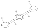
바람직하게는, 상기 자성체는 2개가 마련되고, 상기 끈부는 중심에 홀이 형성된 환형의 제3 끈부와, 상기 제3 끈부에서 제3 방향으로 연장 형성되는 제4 끈부와, 상기 제3 끈부에서 제4 방향으로 연장 형성되는 제5 끈부가 형성되며, 상기 제4 끈부의 단부와 상기 제5 끈부의 단부에는 2개의 상기 자성체를 각각 수용하는 상기 자성체 수용부가 형성될 수 있다.
Preferably, the magnetic body is provided with two, and the string portion has an annular third string portion formed with a hole at the center thereof, a fourth string portion extending in the third direction from the third string portion, A fifth string portion extending in four directions may be formed and the magnetic body receiving portion that accommodates the two magnetic bodies respectively may be formed at the end portion of the fourth string portion and the end portion of the fifth string portion.
본 고안에 따른 정리용 도구에 따르면, 유연한 재질로 형성되는 끈부의 단부에 자력에 의해 상호 붙는 자성체와 이를 수용하는 고정부를 구비함으로써, 액세서리, 사무용 문구, 지류(紙類) 또는 케이블 등과 같은 다양한 물건을 효과적으로 묶거나 고정할 수 있는 유리한 효과를 제공한다.
According to the arranging tool according to the present invention, by providing a magnetic body that is mutually attached to the end portion of the string portion formed of a flexible material by magnetic force and a fixing portion for accommodating the magnetic body, various kinds of accessories such as accessories, office stationery, Thereby providing an advantageous effect of effectively bundling or fixing the objects.
도 1은 본 고안의 바람직한 제1 일실시예에 따른 정리용 도구를 도시한 도면,
도 2는 도 1 에서 도시한 제1 실시예의 분해 사시도,
도 3은 도 1에서 도시한 홀더를 도시한 도면,
도 4는 도 1에서 도시한 제1 실시예로서 자성체가 포함된 2개의 고정부가 자력에 의해 상호 부착된 상태를 도시한 도면,
도 5는 본 고안의 바람직한 제2 실시예에 따른 정리용 도구를 도시한 도면,
도 6은 본 고안의 바람직한 제3 실시예에 따른 정리용 도구를 도시한 도면,
도 7은 본 고안의 바람직한 제4 실시예에 따른 정리용 도구를 도시한 도면,
도 9는 도 1에서 도시한 2개의 제1 실시예가 연결된 상태를 도시한 도면,
도 10은 도 1에서 도시한 제1 실시예의 사용례로서, 칸막이 측벽에 고정하여 액세서리를 정리한 상태를 도시한 도면,
도 11은 도 1에서 도시한 제1 실시예의 사용례로서, 케이블을 묶어 정리한 상태를 도시한 도면,
도 12는 도 1에서 도시한 제1 실시예의 사용례로서, 서류 더미를 고정하여 정리한 상태를 도시한 도면,
도 13은 도 1에서 도시한 제1 실시예의 사용례로서, 책갈피로 사용되는 상태를 도시한 도면이다.FIG. 1 is a view showing a sorting tool according to a first preferred embodiment of the present invention, FIG.
Fig. 2 is an exploded perspective view of the first embodiment shown in Fig. 1,
Fig. 3 is a view showing the holder shown in Fig. 1,
FIG. 4 is a view showing a state where two fixing parts including a magnetic body are mutually attached by a magnetic force, according to the first embodiment shown in FIG. 1;
FIG. 5 is a view showing a sorting tool according to a second preferred embodiment of the present invention; FIG.
FIG. 6 is a view showing a sorting tool according to a third preferred embodiment of the present invention; FIG.
FIG. 7 is a view showing a cleaning tool according to a fourth preferred embodiment of the present invention; FIG.
FIG. 9 is a view showing a state in which two first embodiments shown in FIG. 1 are connected;
Fig. 10 is a use example of the first embodiment shown in Fig. 1, showing a state in which accessories are fixed by being fixed to a partition wall; Fig.
Fig. 11 is a use example of the first embodiment shown in Fig. 1, showing a state in which cables are bundled together, Fig.
Fig. 12 is a use example of the first embodiment shown in Fig. 1,
Fig. 13 is a use example of the first embodiment shown in Fig. 1 and shows a state used as a bookmark.
이하, 본 고안의 바람직한 실시예를 첨부된 도면들을 참조하여 상세히 설명한다. 우선 각 도면의 구성 요소들에 참조 부호를 부가함에 있어서, 동일한 구성 요소들에 대해서는 비록 다른 도면상에 표시되더라도 가능한 한 동일한 부호를 가지도록 하고 있음에 유의해야 한다. 또한, 이하에서 본 고안의 바람직한 실시예를 설명할 것이나, 본 고안의 기술적 사상은 이에 한정하거나 제한되지 않고 당업자에 의해 변형되어 다양하게 실시될 수 있음은 물론이다.
Hereinafter, preferred embodiments of the present invention will be described in detail with reference to the accompanying drawings. In the drawings, the same reference numerals are used to designate the same or similar components throughout the drawings. It will be appreciated that those skilled in the art can change or modify the embodiments without departing from the scope and spirit of the invention.
본 고안은 유연한 끈부와, 끈부에 연결된 자석과 같은 자성체가 상호 부착되어 대상물을 고정하거나 묶어 고정하는 기술적 특징이 있다.
The present invention has a technical feature in which a flexible string portion and a magnetic body such as a magnet connected to a string portion are mutually attached to fix or tie an object.
[제1 실시예][First Embodiment]
도 1은 본 고안의 바람직한 제1 일실시예에 따른 정리용 도구를 도시한 도면이고, 도 2는 도 1 에서 도시한 제1 실시예의 분해 사시도이다.FIG. 1 is a view showing a tool for arranging according to a first preferred embodiment of the present invention, and FIG. 2 is an exploded perspective view of the first embodiment shown in FIG.
이러한, 도 1 및 도 2는 본 고안을 개념적으로 명확히 이해하기 위하여, 주요 특징 부분만을 명확히 도시한 것이며, 그 결과 도해의 다양한 변형이 예상되며, 도면에 도시된 특정 형상에 의해 본 고안의 범위가 제한될 필요는 없다.
1 and 2 clearly show only the main feature parts in order to clearly understand the concept of the present invention and as a result various variations of the illustration are expected and the scope of the present invention Need not be limited.
도 1 및 도 2를 병행 참조하면, 본 고안의 바람직한 제1 실시예에 따른 정리용 도구의 제1 실시예(10)는 적어도 둘의 자성체(100)와, 자성체(100)를 각각 수용하는 적어도 둘의 고정부(200) 및, 유연한 소재로 구성되어 적어도 둘의 고정부(200)와 각각 연결되는 끈부(300)를 포함할 수 있다. 여기서, 고정부(200)와 끈부(300)는 그 형상 및 기능적 특성에 따라 구분되어 설명될 수 있을 뿐. 서로 연결된 하나의 수단일 수 있음을 미리 언급하는 바이다.
1 and 2, a
자성체(100)는 적어도 둘 이상이 마련될 수 있다. 제1 실시예에 있어서, 자성체(100)는 2개가 마련되며 끈부(300)에 연결된 고정부(200)에 각각 수용될 수 있다. 이러한 자성체(100)는 코인형으로 형성될 수 있다. 이는 고정부(200)의 앞면 및 뒷면에서 상호 부착 영역을 확보하기 위함이다.
At least two
고정부(200)는 끈부(300)의 단부에 각각 형성되어 자성체(100)를 수용한다. 각각의 고정부(200)는 자성체(100)의 자력에 의해 서로 맞붙음으로써 대상물에 대한 고정력을 제공한다. 제1 실시예에 있어서, 이러한 고정부(200)는 홀더(210)와, 홀더 수용부(230)를 포함할 수 있다.The
홀더(210)는 내부에 자성체(100)의 수용공간(213)을 형성한다. 수용공간(213)은 코인형 자성체(100)에 대응하여 둥글고 납작한 형태로 형성되어 자성체(100)의 전면, 후면 및 측면 중 적어도 둘을 둘러싸서 탄성적으로 고정하도록 형성될 수 있다. The
도 3은 도 1에서 도시한 홀더를 도시한 도면이다. Fig. 3 is a view showing the holder shown in Fig. 1. Fig.
도 3을 참조하면, 홀더(210)는 둘레면이 경사지게 형성된 걸림부(211)와, 걸림부(211)에 단차지게 결합하는 원통형 몸체(212)를 포함할 수 있다. 걸림부(211)에는 수용공간(213)의 입구가 형성되어 자성체(100)가 삽입될 수 있다. 또한, 걸림부(211)는 홀더 수용부(230)에 탄성 결합하게 된다. 이러한 걸림부(211)는 단부가 잘린 원추형으로 형성되어 원통형 몸체(212)와 단차지게 형성됨으로써, 홀더 수용부(230)에서 빠지지 않도록 고정될 수 있다. Referring to FIG. 3, the
원통형 몸체(212)는 내부에 수용공간(213)의 일부가 형성될 수 있으며, 홀더 수용부(230)의 개방 영역을 덮는 역할을 한다.The
홀더 수용부(230)는 끈부(300)의 양단에서 연장 형성되고 홀더(210)가 삽입 장착되도록 공간을 형성한다. 홀더 수용부(230)는 상면이 개방된 형태로 실시될 수 있으며, 탄성 변형 가능하게 형성될 수 있다. 홀더 수용부(230)의 개방된 상면 직경은 홀더(210)의 걸림부(211) 직경보다 작게 형성되어, 탄성 변형되어 삽입 장착된 걸림부(211)가 빠지지 않도록 구성된다.The
사용자는 홀더 수용부(230)를 확장 변형시켜 홀더(210)를 분리시키고, 홀더(210)에서 자성체(100)를 분리시킬 수 있다.
The user can expand and deform the
본 고안을 설명함에 있어서, 코인형의 자성체(100)에 대응하여 고정부(200)를 납작한 원통형으로 예시하였으나, 본 고안은 이에 한정하지 않으며, 자성체(100)의 형상에 대응하여 다양하게 형성될 수 있다. 또한, 고정부(200)는 자성체(100)의 형상과 무관하게 자성체(100)의 자력에 의해 상호 부착 영역을 확보하는 구성이라면 다양한 형태로 변경 실시될 수 있다.
In the description of the present invention, the fixed
끈부(300)는 유연한 소재로 구성되어 자유롭게 구부러지고 변형 가능하게 형성될 수 있다. 끈부(300)는 엘라스토모 부재로 형성될 수 있으며, 엘라스토모 부재는 천연고무, 합성고무, 실리콘 및 이들의 조합으로 구성될 수 있다. 앞서 기재하였듯이, 끈부(300)는 고정부(200)와 동일한 소재로 구성되어 일체로 형성될 수 있다.
The
보강부재(400)는 도 2에서 도시한 바와 같이, 끈부(300) 내부에 형성되어 끈부(300)의 형태를 잡아주거나 강성을 보강하는 역할을 한다. 보강부재(400)로서 철심이 사용될 수 있으며, 소정의 길이로 형성되는 복수 개의 보강부재(400)가 끈부(300) 내부에 설치될 수 있다.
As shown in FIG. 2, the reinforcing
도 4는 도 1에서 도시한 제1 실시예로서 자성체가 포함된 2개의 고정부가 자력에 의해 상호 부착된 상태를 도시한 도면이다.FIG. 4 is a view showing a state where two fixing parts including a magnetic body are mutually attached by a magnetic force as the first embodiment shown in FIG.
도 4를 참조하면, 끈부(300) 구부러져 끈부(300)의 양 단에 형성된 고정부(200)가 상호 자력에 의해 맞붙음으로써, 대상물을 묶거나 고정시킬 수 있음을 확인할 수 있다. 이때, 끈부(300)의 길이 및 직경은 용도에 따라 변경 실시될 수 있으며, 끈부(300)의 길이 및 직경에 따라 고정부(200)의 크기도 달리 할 수 있다.
Referring to FIG. 4, it can be seen that the objects can be bundled or fixed by bending the
[제2 실시예][Second Embodiment]
도 5는 본 고안의 바람직한 제2 실시예에 따른 정리용 도구를 도시한 도면이다.FIG. 5 is a view showing a cleaning tool according to a second preferred embodiment of the present invention. FIG.
도 5에 도시된 본 고안에 따른 제2 실시예는, 전술된 제1 실시예에 따른 끈부(300)가 제1 끈부(310)와 제2 끈부(320)로 구성되고, 제1 끈부(310)와 제2 끈부(320) 양단에는 각각 모두 4개의 고정부(200)가 마련된 것이다. 자성체(100)는 모두 4개가 마련될 수 있다. 각 고정부(200)의 구성은 제1 실시예와 동일하므로, 중복되는 설명은 생략한다.The second embodiment according to the present invention shown in Fig. 5 is characterized in that the
제1 끈부(310)와 제2 끈부(320)는 서로 수직 교차하여 십자 형태로 구성될 수 있다.
The
[제3 실시예][Third Embodiment]
도 5는 본 고안의 바람직한 제2 실시예에 따른 정리용 도구를 도시한 도면이다.FIG. 5 is a view showing a cleaning tool according to a second preferred embodiment of the present invention. FIG.
도 5에서 도시된 본 고안에 따른 제3 실시예는 전술된 제1 실시예에 따른 끈부(300)가 메인 끈부(330)와, 메인 끈부(330)의 양단 중 어느 일단에는 2개의 제1 분지형 끈부(341,342)가 형성되고, 메인 끈부(330)의 양단 중 다른 일단에는 2개의 제2 분지형 끈부(351,352)가 형성되며, 제1 분지형 끈부(341,342)와 제2 분지형 끈부(351,352)의 단부에는 각각 모두 4개의 고정부(200)가 마련된 것이다. 자성체(100)는 모두 2개가 마련될 수 있다.The third embodiment according to the present invention shown in FIG. 5 differs from the first embodiment in that the
각 고정부(200)의 구성은 제1 실시예와 동일하므로, 중복되는 설명은 생략한다.
Since the constructions of the fixing
[제4 실시예][Fourth Embodiment]
도 7은 본 고안의 바람직한 제4 실시예에 따른 정리용 도구를 도시한 도면이다.FIG. 7 is a view showing a cleaning tool according to a fourth preferred embodiment of the present invention. FIG.
도 7에서 도시된 본 고안에 따른 제4 실시예는 제1 실시예에 따른 끈부(300)가 중심에 홀이 형성된 환형의 제3 끈부(360)와, 제3 끈부(360)에서 연장 형성되는 제4 끈부(370)와, 상기 제3 끈부에서 연장 형성되는 제5 끈부(380)가 형성되며, 제4 끈부(370)의 단부와 상기 제5 끈부(380)의 단부에는 2개의 고정부(200)가 마련된 것이다. 자성체(100)는 모두 2개가 마련될 수 있다. 제4 끈부(370)와 제5 끈부(380)는 제3 끈부(360)를 중심으로 상호 대향하여 연장 형성될 수 있다.The fourth embodiment according to the present invention shown in Fig. 7 is similar to the fourth embodiment in that the
환형의 제3 끈부(360)에는 대상물의 일부가 삽입되거나 소정의 구조물의 일부가 삽입될 수 도 있다. 각 고정부(200)의 구성은 제1 실시예와 동일하므로, 중복되는 설명은 생략한다.
A part of the object may be inserted or a part of the predetermined structure may be inserted into the annular
이하, 도 9 내지 도 13을 참조하여, 본 고안에 따른 제1 실시예의 사용례들을 설명한다.Hereinafter, with reference to Figs. 9 to 13, the use examples of the first embodiment according to the present invention will be described.
도 9는 도 1에서 도시한 2개의 제1 실시예가 연결된 상태를 도시한 도면이다.FIG. 9 is a diagram showing a state in which two first embodiments shown in FIG. 1 are connected.
도 9에서 도시한 바와 같이, 제1 실시예(10)를 타방의 정리 도구(20)와 연결하여 사용할 수 있다. 다시 말해서, 일방의 정리 도구(10)의 고정부 중 어느 하나와 타방의 정리 도구(20)의 고정부 중 어느 하나를 자력에 의해 서로 연결되게 구성하여 실시할 수 있다. 이렇게 복수 개의 정리 도구(10,20...)들을 선형적으로 연결하여 용도에 맞게 변형 실시할 수 있다.
As shown in FIG. 9, the
도 10은 도 1에서 도시한 제1 실시예의 사용례로서, 칸막이 측벽에 고정하여 액세서리를 정리한 상태를 도시한 도면이다.Fig. 10 is a use example of the first embodiment shown in Fig. 1, showing a state in which the accessories are fixed by being fixed to the side wall of the partition. Fig.
도 10에서 도시된 본 고안에 따른 제1 실시예(10)의 사용례는, 2개의 고정부(200) 중 어느 하나에 스템플러 제거 도구(P1)를 부착하고, 2개의 고정부(200) 중 다른 하나는 철재로 구성되는 칸막이에 부착시키는 형태일 수 있다. 스템플러 제거 도구(P1) 이외에 클립과 같은 금속소재의 문구 등을 고정부(200)에 동시에 부착시킴으로써, 책상 위에 산재되어 있는 문구 또는 액세서리들을 깔끔하게 정리하는 것이 가능하다.
The use of the
도 11은 도 1에서 도시한 제1 실시예의 사용례로서, 케이블을 묶어 정리한 상태를 도시한 도면이다.Fig. 11 is a use example of the first embodiment shown in Fig. 1 and shows a state in which cables are bundled together.
도 11에서 도시된 본 고안에 따른 제 실시예(10)의 사용례는. 끈부(300)로 케이블(P2)을 감고, 끈부(300)의 양단에 형성된 고정부(200)가 자력에 의해 상호 부착됨으로써, 케이블(P2)을 감은 끈부(300)를 고정하는 형태일 수 있다.
An example of the use of the
도 12는 도 1에서 도시한 제1 실시예의 사용례로서, 서류를 고정하여 정리한 상태를 도시한 도면이다. 도 12에서 도시된 본 고안에 따른 제 실시예(10)의 사용례는, 끈부(300)의 양단에 형성된 고정부(200) 사이에 서류(P3)를 넣으면, 대향하여 배치된 고정부(200)의 인력으로 서류를 고정할 수 있게 된다. 이외에 메모지 등을 고정하여 철재 칠판이나 철재 고정물에 부착하는 형태로 실시될 수 있다.
Fig. 12 is an example of use of the first embodiment shown in Fig. 1, and shows a state in which documents are fixed and arranged. The use of the
도 13은 도 1에서 도시한 제1 실시예의 사용례로서, 책갈피로 사용되는 상태를 도시한 도면이다.Fig. 13 is a use example of the first embodiment shown in Fig. 1 and shows a state used as a bookmark.
도 13에서 도시된 본 고안에 따른 제 실시예(10)의 사용례는, 끈부(300)의 양단에 형성된 고정부(200) 중 어느 하나를 책(P4)의 읽던 페이지에 끼워 놓고, 고정부(200) 중 다른 하나를 책(P4)의 표지에 위치시켜 책갈피로서 사용하는 형태일 수 있다.An example of use of the
위와 같이, 본 고안에 따른 제1 실시예의 사용례를 설명하였으나. 본 고안은 이에 한정되지 않으며, 정리 대상물의 종류에 따라 다양하게 변경 실시될 수 있다.
As described above, the use example of the first embodiment according to the present invention has been described. The present invention is not limited to this, and various modifications may be made depending on the kind of the object to be sorted.
이상의 설명은 본 고안의 기술 사상을 예시적으로 설명한 것에 불과한 것으로서, 본 고안이 속하는 기술 분야에서 통상의 지식을 가진 자라면 본 고안의 본질적인 특성에서 벗어나지 않는 범위 내에서 다양한 수정, 변경 및 치환이 가능할 것이다. 따라서, 본 고안에 개시된 실시예 및 첨부된 도면들은 본 고안의 기술 사상을 한정하기 위한 것이 아니라 설명하기 위한 것이고, 이러한 실시예 및 첨부된 도면에 의하여 본 고안의 기술 사상의 범위가 한정되는 것은 아니다. 본 고안의 보호 범위는 아래의 청구범위에 의하여 해석되어야 하며, 그와 동등한 범위 내에 있는 모든 기술 사상은 본 고안의 권리범위에 포함되는 것으로 해석되어야 할 것이다.
It will be understood by those skilled in the art that various modifications, substitutions and alterations can be made hereto without departing from the spirit and scope of the invention as defined by the appended claims. will be. Therefore, the embodiments disclosed in the present invention and the accompanying drawings are intended to illustrate and not to limit the technical idea of the present invention, and the scope of the technical idea of the present invention is not limited by these embodiments and the accompanying drawings . The scope of protection of the present invention should be construed according to the following claims, and all technical ideas which are within the scope of the same should be interpreted as being included in the scope of the present invention.
100 : 자성체
200 : 고정부
210 : 홀더
211 : 걸림부
212 : 원통형 몸체
213 : 수용홈
230 : 홀더 수용부
300 : 끈부
310 : 제1 끈부
320 : 제2 끈부
330 : 메인 끈부
341,342 : 제1 분지형 끈부
351,352 : 제2 분지형 끈부
360 : 제3 끈부
370 : 제4 끈부
380 : 제5 끈부
400 : 보강부재100: magnetic substance
200:
210: holder
211:
212: Cylindrical body
213: receiving groove
230: holder holder
300: Ties
310: first tie
320: second tie
330: main strap
341,342: The first bifurcation tying
351,352: the second bifurcation tying
360: third tie
370: 4th strap
380: fifth string
400: reinforcing member
Claims (11)
상기 자성체를 각각 수용하는 적어도 둘의 고정부;및
유연한 소재로 구성되어 적어도 둘의 상기 고정부와 각각 연결되는 끈부를 포함하고,
상기 끈부 및 적어도 둘의 상기 고정부는 유연한 소재로 일체로 성형되며,
상기 자성체는 코인형으로 구성되고, 상기 고정부는 코인형으로 구성되는 상기 자성체의 전면, 후면 및 측면 중 적어도 둘을 둘러싸서 탄성적으로 고정하며,
여기서, 상기 고정부는, 상기 자성체를 수용하는 수용공간이 형성된 홀더와, 상기 끈부에서 연장 형성되어 상기 홀더가 탄성 결합하는 홀더 수용부를 포함하는 것을 특징으로 하는 고정용 도구.
At least two magnetic bodies;
At least two fixing portions each of which houses the magnetic body;
And a cord portion made of a flexible material and connected to at least two of said fixing portions,
The string portion and at least two of the fixing portions are integrally formed of a flexible material,
Wherein the magnetic body is constituted by a coin type and the fixed portion surrounds and elastically fixes at least two of the front surface, the rear surface and the side surface of the magnetic body formed in a coin shape,
Wherein the fixing portion includes a holder having a housing space for accommodating the magnetic body, and a holder accommodating portion extended from the string portion and elastically coupled with the holder.
상기 홀더는 둘레면이 경사지게 형성된 걸림부와 상기 걸림부에 단차지게 결합하는 원통형 몸체를 포함하는 것을 특징으로 하는 고정용 도구.
The method according to claim 1,
Wherein the holder includes a latching portion having a circumferential surface inclined and a cylindrical body steppedly engaged with the latching portion.
상기 자성체는 2개가 마련되고, 상기 끈부의 양단에는 2개의 상기 자성체를 각각 수용하는 2개의 상기 고정부가 각각 형성되는 것을 특징으로 하는 고정용 도구.
6. The method according to claim 1 or 5,
Wherein two magnetic bodies are provided, and at both ends of the string portion, two fixing portions each of which accommodates the two magnetic bodies are respectively formed.
상기 끈부의 내부에는 적어도 하나의 선형의 보강부재가 설치되는 것을 특징으로 하는 고정용 도구.
The method according to claim 6,
Wherein at least one linear reinforcing member is provided in the interior of the strap.
상기 자성체는 4개가 마련되고, 상기 끈부는 제1 방향으로 길게 형성되는 제1 끈부와 제2 방향으로 길게 형성되어 상기 제1 끈부와 교차하도록 형성되는 제2 끈부로 구성되고, 상기 제1 끈부의 양단 및 상기 제2 끈부의 양단에는 4개의 상기 자성체를 각각 수용하는 상기 고정부가 형성되는 것을 특징으로 하는 고정용 도구.
The method according to claim 1,
Wherein the magnetic substance body includes four magnetic pieces, the first magnetic piece includes a first magnetic piece, a first magnetic piece, a second magnetic piece, and a second magnetic piece, And both ends of the second string portion are formed with the fixing portions that respectively receive the four magnetic bodies.
상기 제1 끈부와 상기 제2 끈부는 수직하게 교차하는 것을 특징으로 하는 고정용 도구.
9. The method of claim 8,
And the first string portion and the second string portion intersect perpendicularly.
상기 자성체는 4개가 마련되고, 상기 끈부는 메인 끈부와 상기 메인 끈부의 양단 중 어느 일단에는 2개의 제1 분지형 끈부가 형성되고, 상기 메인 끈부의 양단 중 다른 일단에는 2개의 제2 분지형 끈부가 형성되며, 2개의 상기 제1 분지형 끈부의 단부 및 2개의 제2 분지형 끈부의 단부에는 4개의 상기 자성체를 각각 수용하는 상기 자성체 수용부가 각각 형성되는 것을 특징으로 하는 고정용 도구.
The method according to claim 1,
Wherein the magnetic body is provided with four magnetic strings, and the string portion is formed with two first bifurcated straps at either one end of the main string portion and at both ends of the main string portion, and at the other end of the main string portion, And the magnetic body accommodating portions for respectively receiving the four magnetic bodies are respectively formed at the end portions of the two first branching straps and the end portions of the two second branching straps.
상기 자성체는 2개가 마련되고, 상기 끈부는 중심에 홀이 형성된 환형의 제3 끈부와, 상기 제3 끈부에서 제3 방향으로 연장 형성되는 제4 끈부와, 상기 제3 끈부에서 제4 방향으로 연장 형성되는 제5 끈부가 형성되며, 상기 제4 끈부의 단부와 상기 제5 끈부의 단부에는 2개의 상기 자성체를 각각 수용하는 상기 자성체 수용부가 형성되는 것을 특징으로 하는 고정용 도구.The method according to claim 1,
Wherein the magnetic substance is provided with two magnetic pieces, the string portion has an annular third string portion formed with a hole at the center thereof, a fourth string portion extending in the third direction from the third string portion, and a fourth string portion extending from the third string portion in the fourth direction And the magnetic body accommodating portion for accommodating the two magnetic bodies is formed at the end of the fourth string portion and the end of the fifth string portion.
Priority Applications (3)
| Application Number | Priority Date | Filing Date | Title |
|---|---|---|---|
| KR2020130000977U KR200466917Y1 (en) | 2013-02-06 | 2013-02-06 | Fixing device |
| JP2015600127U JP3203663U (en) | 2013-02-06 | 2013-06-11 | Fixing tool |
| PCT/KR2013/005137 WO2014123282A1 (en) | 2013-02-06 | 2013-06-11 | Fixing tool |
Applications Claiming Priority (1)
| Application Number | Priority Date | Filing Date | Title |
|---|---|---|---|
| KR2020130000977U KR200466917Y1 (en) | 2013-02-06 | 2013-02-06 | Fixing device |
Publications (1)
| Publication Number | Publication Date |
|---|---|
| KR200466917Y1 true KR200466917Y1 (en) | 2013-05-15 |
Family
ID=51299861
Family Applications (1)
| Application Number | Title | Priority Date | Filing Date |
|---|---|---|---|
| KR2020130000977U KR200466917Y1 (en) | 2013-02-06 | 2013-02-06 | Fixing device |
Country Status (3)
| Country | Link |
|---|---|
| JP (1) | JP3203663U (en) |
| KR (1) | KR200466917Y1 (en) |
| WO (1) | WO2014123282A1 (en) |
Families Citing this family (1)
| Publication number | Priority date | Publication date | Assignee | Title |
|---|---|---|---|---|
| EP3400178A4 (en) | 2016-01-04 | 2019-05-15 | Nite Ize, Inc. | Systems and methods for a cord holder |
Family Cites Families (9)
| Publication number | Priority date | Publication date | Assignee | Title |
|---|---|---|---|---|
| JPS53157086U (en) * | 1977-05-16 | 1978-12-09 | ||
| JPS5876558U (en) * | 1981-11-18 | 1983-05-24 | 田尾 孝行 | Binding tools for fishing rods, etc. |
| JPH0166361U (en) * | 1987-10-23 | 1989-04-27 | ||
| JPH0719156U (en) * | 1993-09-16 | 1995-04-07 | 株式会社ニュークラフト | Simple tightening tool |
| JPH0743374U (en) * | 1993-12-31 | 1995-08-22 | 博一 飯野 | Paper sandwich with magnets on both ends of the string |
| JPH08133331A (en) * | 1994-11-02 | 1996-05-28 | Hoomuzu Kk | Band tool for cross-tying |
| HK1045780A2 (en) * | 2001-07-09 | 2002-12-06 | Sheung Chung Wong | Magnetic strap fastener |
| JP2005030581A (en) * | 2003-07-11 | 2005-02-03 | Makoto Takahashi | Magnet with strong hook |
| KR200365447Y1 (en) * | 2004-07-28 | 2004-10-26 | 정재경 | Maget using gloves coupling |
-
2013
- 2013-02-06 KR KR2020130000977U patent/KR200466917Y1/en active IP Right Grant
- 2013-06-11 JP JP2015600127U patent/JP3203663U/en not_active Expired - Fee Related
- 2013-06-11 WO PCT/KR2013/005137 patent/WO2014123282A1/en active Application Filing
Also Published As
| Publication number | Publication date |
|---|---|
| WO2014123282A1 (en) | 2014-08-14 |
| JP3203663U (en) | 2016-04-14 |
Similar Documents
| Publication | Publication Date | Title |
|---|---|---|
| AU2016211994B2 (en) | Elongate attachable flexible magnetic article holder | |
| DK3091752T3 (en) | CABLE COLLECTOR | |
| US11465818B2 (en) | Systems and methods for securing cords | |
| US9124053B2 (en) | Cordage restraint and management system | |
| US9108779B1 (en) | Wire tie device | |
| KR200457847Y1 (en) | A cable arrenge bend | |
| KR200466917Y1 (en) | Fixing device | |
| US10069290B2 (en) | Surface mounted multiple cable or wire organizer | |
| KR102024762B1 (en) | Link cable tie | |
| KR101778125B1 (en) | Cable binder | |
| AU2005100034A4 (en) | An Electrical Plug | |
| JP3232098U (en) | Tags and cable ties with tags | |
| JP3208736U (en) | Tying tool | |
| JP2016010852A (en) | file | |
| KR20170016250A (en) | Apparatus for wire arrangement | |
| CN215924056U (en) | Data line storage box | |
| KR20080003053U (en) | Cable tie for packing | |
| JP5074933B2 (en) | Wiring display device | |
| CN208345488U (en) | A kind of primary and secondary modularization Pipeline clip | |
| JP3119073U (en) | Binding strap fastener | |
| KR20160004250A (en) | Folding wire | |
| KR200473801Y1 (en) | Paper Holder File Having Clips | |
| JP3196459U (en) | Earphone cord ties | |
| JP2011082884A (en) | Earphone device | |
| KR20060096959A (en) | The cable order tool |
Legal Events
| Date | Code | Title | Description |
|---|---|---|---|
| A201 | Request for examination | ||
| A302 | Request for accelerated examination | ||
| E902 | Notification of reason for refusal | ||
| E701 | Decision to grant or registration of patent right | ||
| REGI | Registration of establishment | ||
| FPAY | Annual fee payment |
Payment date: 20160311 Year of fee payment: 4 |
|
| FPAY | Annual fee payment |
Payment date: 20180531 Year of fee payment: 6 |
|
| FPAY | Annual fee payment |
Payment date: 20190423 Year of fee payment: 7 |
|
| FPAY | Annual fee payment |
Payment date: 20200220 Year of fee payment: 8 |