KR200406764Y1 - Integral Screen and Cylindrical Sand Remover - Google Patents
Integral Screen and Cylindrical Sand Remover Download PDFInfo
- Publication number
- KR200406764Y1 KR200406764Y1 KR2020050027940U KR20050027940U KR200406764Y1 KR 200406764 Y1 KR200406764 Y1 KR 200406764Y1 KR 2020050027940 U KR2020050027940 U KR 2020050027940U KR 20050027940 U KR20050027940 U KR 20050027940U KR 200406764 Y1 KR200406764 Y1 KR 200406764Y1
- Authority
- KR
- South Korea
- Prior art keywords
- tank
- sand
- sewage
- contaminants
- drum screen
- Prior art date
Links
Images


Classifications
-
- B—PERFORMING OPERATIONS; TRANSPORTING
- B01—PHYSICAL OR CHEMICAL PROCESSES OR APPARATUS IN GENERAL
- B01D—SEPARATION
- B01D21/00—Separation of suspended solid particles from liquids by sedimentation
- B01D21/26—Separation of sediment aided by centrifugal force or centripetal force
- B01D21/265—Separation of sediment aided by centrifugal force or centripetal force by using a vortex inducer or vortex guide, e.g. coil
-
- B—PERFORMING OPERATIONS; TRANSPORTING
- B01—PHYSICAL OR CHEMICAL PROCESSES OR APPARATUS IN GENERAL
- B01D—SEPARATION
- B01D21/00—Separation of suspended solid particles from liquids by sedimentation
- B01D21/24—Feed or discharge mechanisms for settling tanks
- B01D21/245—Discharge mechanisms for the sediments
- B01D21/2461—Positive-displacement pumps; Screw feeders; Trough conveyors
Abstract
본 고안은 하수 및 오.폐수의 협잡물처리기에서 그릴 모양의 드럼 스크린이 폐수로 유입되는 협잡물을 분리하는 스크린부, 협잡물을 이송하는 이송부, 이송된 협잡물을 압축하는 압축부로 구성되는 협잡물처리기에 있어서, 협잡물과 모래가 같이 유입되는 하수 및 오.폐수가 그릴 모양의 드럼 스크린을 통과하면서 크기가 상당한 협잡물은 드럼 스크린에서 여과되어 처리되며 드럼 스크린을 통과한 모래는 원통형 탱크를 통과하게 되고 이때 공기를 분사시켜 와류를 형성하여 모래의 침전을 보다 효과적으로 할 수 있게 하며, 동시에 공기 분사에 의해 오염된 모래를 세척하면서 탱크의 저부에 형성된 스크류콘베어에 모이게 하고 이송함으로서 깨끗한 모래로 처리할 수 있는 모래제거기를 제공하고자 하는 것이다.The present invention, in the sewage and sewage treatment system of the sewage and sewage waste, the grill-shaped drum screen is composed of a screen unit for separating the contaminants introduced into the wastewater, a conveying unit for transporting the contaminants, compression unit for compressing the transported contaminants, Sewage and wastewater, which enters the contaminants and sand together, passes through the grill-shaped drum screen, and significant contaminants are filtered out of the drum screen and sand passed through the drum screen passes through the cylindrical tank, where air is sprayed. To form a vortex to make sand more effective, and at the same time to clean the contaminated sand by air injection, gathering and transporting it to the screw conveyor formed at the bottom of the tank, and providing sand remover that can be treated with clean sand. I would like to.
Description
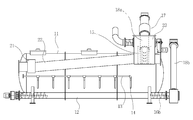
도 1은 본 고안의 전체도1 is an overall view of the present invention
도 2는 본 고안의 측면도2 is a side view of the present invention
도 3은 본 고안의 상세도3 is a detailed view of the present invention
도 4는 본 고안의 탱크의 단면도4 is a cross-sectional view of the tank of the present invention
* 도면의 주요 부분에 대한 부호의 설명** Explanation of symbols for main parts of the drawing
11 : 탱크 12 : 챔버11
13 : 공기공급관 14 : 분사구 13: air supply pipe 14: injection hole
15 : 드럼 스크린 16 : 스크류(a,b,c) 15 drum screen 16 screw (a, b, c)
17 : 압축관 18 : 이송관(a,b)17: compression pipe 18: feed pipe (a, b)
19 : 유입관 21 : 배출관19: inlet pipe 21: discharge pipe
22 : 오버플로워관 23 : 수용함22: overflow hall 23: housed
24 : 홈 25 : 모래24: Home 25: Sand
본 고안은 오수 및 폐수의 협잡물처리장치의 원통형 탱크에 관한 것으로, 상세하게는 협잡물과 모래를 포함하는 오수가 수용함에 유입되어 협잡물은 드럼 스크린에서 걸러지고 모래는 드럼 스크린을 통과하여 원통형 탱크로 유입되어 탱크의 길이에 걸처 이동하면서 탱크 내벽에 노출된 다수개의 분사구에서 공기가 분출되어 오수를 와류시켜 오수의 수평 흐름을 둔화시키고 원통형 탱크 내벽을 따라 오수가 회류하고 비중이 큰 모래는 탱크 내벽에 부딪혀 하중에 의해 하강하여 쳄버에 모이며 오수가 와류되는 과정에서 공기 분사에 의해 모래에 씌워진 오물이 세척되도록 구성된 원통형 모래제거기에 관한 것이다. The present invention relates to a cylindrical tank of a sewage and wastewater contaminant treatment apparatus, and in particular, the sewage containing the contaminant and sand flows into the container, and the contaminants are filtered out from the drum screen , and the sand passes through the drum screen into the cylindrical tank. Air is blown out from a plurality of nozzles exposed to the tank inner wall as it travels over the length of the tank, vortexing the sewage to slow the horizontal flow of sewage, and the sewage flows along the inner wall of the cylindrical tank, and the heavy sand hits the tank inner wall The present invention relates to a cylindrical sand remover configured to wash down dirt collected on sand by air injection during sewage vortex, which is lowered by load and collected in a chamber.
종래의 협잡물처리장치는 협잡물이 처리된 후 오수 중 모래를 제거하기 위해큰 침전탱크가 필요하였고 이로 인해 설치가 어렵고 장비가격 및 토목 구조에 소요되는 비용이 상승하는 문제점이 있다. Conventional contaminant treatment apparatus has a large sedimentation tank is required to remove the sand in the sewage after the contaminants are processed, which is difficult to install and the cost of equipment and civil engineering structure increases.
본 고안은 오. 폐수 처리장치의 입수부에서 협잡물을 걸러내는 드럼 스크린과 연계하여 원통형 내벽에 길이에 걸쳐 다수개의 공기 분사구를 형성하고 탱크 저부에는 별도의 챔버를 부착하여 일체형으로 형성하고 탱크의 내부와 챔버의 내부가 그 길이에 걸처 연결이 되도록 형성한 후, 상기 챔버 내부에 모래를 이송할 수 있는 스크류컨베이어를 설치하고 모래를 포함하는 오수가 드럼 스크린을 통과하여 탱크에 수용되면 분사구에서 공기가 분사되어 오수가 와류를 일으키게 하므로서 오수는 탱크에서 상당한 시간을 체류하고 침전 효과가 높아져 작은 크기의 모래까지 침전시켜 처리할 수 있으며 체류하는 동안 공기 분사에 의해 모래를 제거하는 장치를 제공하는데 그 목적이 있다.This design is oh. In conjunction with the drum screen that filters the contaminants from the inlet of the wastewater treatment system, a plurality of air inlets are formed on the cylindrical inner wall over the length, and a separate chamber is attached to the bottom of the tank to form a single body. After the connection is formed over its length, a screw conveyor for transporting sand is installed inside the chamber, and when the sewage containing sand passes through the drum screen and is received in the tank, air is injected from the injection hole so that the sewage vortex The purpose of the present invention is to provide a device for removing sewage by air injection during the dwelling process, which can be treated by sedimentation to a small size of sand due to the retention of considerable time in the tank and the increased sedimentation effect.
오수가 최대한 탱크에 오래 체류하여 더 많은 모래가 침전할 수 있도록 하기 위해 오수의 배출 위치를 오수의 유입 방향에서 원 거리에 위치케 하고 탱크의 윗 부분에 위치하며 오수의 수용함에 설치된 오버플로워(overflower)관과 연결되도록 한다.To ensure that the sewage stays in the tank as long as possible so that more sand can settle, the discharge location of the sewage is located far away from the inflow direction of the sewage, located in the upper part of the tank, Connect to the pipe.
드럼 스크린과 이송관이 설치되는 수용함은 협잡물이 압축되어 물이 배출될 때 그 물을 수용할 수 있도록 구성하며 수용함에 유입되는 오수가 갑자기 많아지면 오버플로워 (overflower)관에 의해 많아진 정도의 오수가 배출되도록 한다. The container where the drum screen and the conveying pipe are installed is configured to receive the water when the debris is compressed and the water is discharged. If the sewage flowing into the container suddenly increases, the amount of sewage increased by the overflow tube To be discharged.
분사구의 공기 분사량은 오수의 오염 정도에 따라 분사량을 조절할 수 있도록 하고 조절 밸브는 탱크 밖에 설치하여 작동이 용이하도록 한다.The air injection amount of the injection port can adjust the injection amount according to the degree of contamination of the sewage, and the control valve is installed outside the tank for easy operation.
오수의 수용함(23)과 탱크(11)는 일체형으로 형성되어 도 1에 도시된 것과 같이 오수함(23) 일부가 탱크(11)에 포함되는 구조이다.
본 고안은 협잡물을 포함하는 오수를 수용함(23)과 수용함(23)에 거치 고정되어 협잡물을 걸러 내는 드럼 스크린(15)과 드럼 스크린(15)과 일체형으로 형성되고 드럼 스크린(15) 내의 협잡물을 이송하고 탈수하는 이송관(18a)과 이송된 협잡물을 압착하고 탈수시키는 압축관(17)으로 구성되는 모래제거기에 있어서, 수용함(23)과 연계되고 수용함과 일체형으로 형성된 탱크(11)가 수용함(23)의 오수를 수용하고 배출시키는 과정에서 탱크(11) 벽에 형성된 다수개의 분사구(13)에서 고압으로 분사되는 공기에 의해 오수에 포함되는 모래(25)를 최대한 많은 양이 침전되도록 하고 동시에 세척시킬 수 있도록 구성된 것이다.The present invention is integrally formed with the
오수를 수용하며 드럼 스크린(15)이 수용되는 오수함(23)과, 유입되는 오수가 많아지면 많아진 것 만큼 퇴출시키는 오버플로워관(22)과, 오수함(23)에서 드럼스크린(15)으로 걸러지고 배출되는 오수를 수용하는 탱크(11)와, 탱크(11)에 공기를 분사하는 분사구(14)를 포함하는 공기 공급관(13)과, 모래(25)가 침전되어 쌓이는 모래(25)를 한 방향으로 이송시키는 스크류콘베어(16a)를 포함하는 챔버(12)로 구성된다.A
도 1은 본 고안에 의한 협잡물처리장치의 전체를 도시하기 위한 것이고, 도 2는 본 고안에 의한 협잡물처리장치의 구조를 도시하기 위한 것이며, 도 3은 본 고안에 의한 탱크의 구조를 상세히 도시한 것이다.Figure 1 is for showing the whole of the contaminant treatment apparatus according to the present invention, Figure 2 is to show the structure of the contaminant treatment apparatus according to the present invention, Figure 3 shows the structure of the tank according to the present invention in detail will be.
본 고안은 이송관(18a)의 하부에 장착된 드럼 스크린(15)과, 드럼 스크린(15)에 집적된 협잡물을 이송시키는 콘베어 스크류(16b)가 내재된 이송관(18a)과, 이송되는 협잡물을 압축 탈수하여 케이크화시키는 압축관(17)으로 구성되어 협잡물을 처리하는 종래의 장치를 개선한 것이다.The present invention provides a
도 1에 도시된 것과 같이 드럼 스크린(15)과 이송관(18a)의 일부를 수용하고 수로로부터 유입되는 오수를 수용하는 수용함(23)이 구성된다.As shown in FIG. 1, a
상기 수용함(23) 상부에는 수로에서 유입되는 오수의 량이 많을 때, 오수를 퇴출할 수 있는 오버플로워관(22)이 형성된다.In the upper portion of the
오. 폐수는 유입관(19)을 통하여 수용함(23)에 유입된다.Five. Waste water is introduced into the receiving container (23) through the inlet pipe (19).
수용함(23)의 오. 폐수는 수용함(23)에서 직접 탱크(11)에 유입된다.O in the
상기 수용함(23)에서 탱크(11)로 유입되는 오수는 드럼 스크린(15)에서 협잡물이 걸러진 오수이다.The sewage flowing into the
상기 탱크(11)는 원통형으로 형성하되 모래를 침전시킬 수 있는 최소의 길이를 갖도록 구성된다. The
탱크(11)가 원형인 것은 탱크(11) 내벽이 곡면이 되게 함으로서 오수의 와류 형성을 쉽게 하고 곡면에 쌓이는 모래(25)가 곡면인 내벽을 타고 서서히 하강하도록 한 구성이다.The circular shape of the
탱크(11)에는 오수배출관(21)이 형성되고 오버플로워관(22)과 연결된다. 도 3에 도시된 것과 같이 탱크(11) 양 벽에는 분사구(14)이 배치되고 송풍기와 연결된공기공급관(13)으로부터 공기를 공급받아 분사하도록 구성된다.The
탱크(11) 하부에는 탱크(11)의 길이에 걸쳐 개방되어 소정의 폭으로 홈(24)이 형성되며 홈(24) 아래에는 그 내부가 홈(24)과 연결되는 챔버(12)가 형성된다.The lower part of the
상기 챔버(12) 내부에는 그 길이에 걸처 스크류콘베어(16a)가 설치되고 모래(25)를 이송할수 있도록 구성된다.Inside the
본 고안을 실시 예로 설명한다.The present invention will be described as an example.
본 고안은 종래에 사용되는 협잡물처리장치에서 처리하는 경우 협잡물을 처리하는 과정에서 드럼 스크린(15)을 통과하는 오수 중 모래(25)를 충분하게 침전하기 위해 큰 탱크가 필요한 문제점이 있고, 수거되는 모래(25)가 오물이 접착된 상태이기 때문에 재사용하기 위해 다시 세척하는 곤란함이 있으며, 세척을 하게 되면 또다시 오수가 발생하는 문제점을 개선하기 위해 오수에서 협잡물과 모래(25)를 분하여 처리할 때 충분한 모래(25)의 수거와 세척을 동시에 이룰 수 있는 장치를 제공하는 것이다.The present invention has a problem that a large tank is needed to sufficiently settle the sand 25 in the sewage passing through the
협잡물과 모래(25)를 포함하는 오수가 수로에서 수용함(23)에 수용되면 드럼스크린(15)의 스크레파(도시되지않음)가 작동하여 드럼 스크린(15) 내경에 부착되는 협잡물을 이송관(18a)의 하부에 모아주면 이송관(18a)의 스크류콘베어(16b)가 회전하여 협잡물을 압축관(17)으로 이송하게 되고 압축관(17)에서 압축 탈수된 협잡물은 케이크화되어 배출된다. Impurities and when the waste water containing the sand 25 is accommodated in a box accommodated in the
상기와 같은 과정에서 협잡물이 걸러진 오수는 원통형 탱크(11)에 유입된다. 수로의 오수 유입량이 많아지게 되면 오수가 수용함(23)을 넘치지 않도록 수용함(23)의 상부에 오버플로워관(22)을 설치하여 오수가 수용함(23)을 넘치지 않도록 한다.Sewage from which the contaminants are filtered in the above process is introduced into the cylindrical tank (11). When the amount of sewage inflow into the waterway increases, the
상기 수용함(23)의 드럼 스크린(15)은 수용함(23)의 내벽에 밀착되는 구조이므로 드럼 스크린(15)을 통과하는 오수의 협잡물은 드럼 스크린(15)에서 차단되므로 탱크(11)로 유입되는 오수에는 협잡물은 포함되지 않는다.In the waste water contaminants are therefore cut off from the
탱크(11)의 위치는 탱크(11)에 유입되는 오수는 탱크(11) 체적의 80%정도에서 배출되도록 구성하는 것이 바람직하다. The position of the
탱크(11)에 오수가 채워지면 공기공급관(13)으로 유입되는 공기가 분사구(14)를 이용하여 고압으로 분사하게 된다. 탱크(11)에 수용되는 오수의 량에 따라 분사량(14)을 조절할 수 있고 오수의 오염 정도에 따라 분사구(14) 이용을 조절할 수 있다.When the
상기와 같이 탱크(11)에 공기 분사를 하는 일차적 이유는, 탱크(11)에 유입되는 오수는 수로의 유속과 같을 것이므로 탱크(11)의 와류를 형성하여 유속을 둔화켜 모래 침전을 보다 효율적으로 하기 위한 것이고, 이차적 이유는 모래(25)의 세척을 위한 것이다.As described above, the primary reason for injecting air into the
탱크(11)에 설치된 공기 분사구(14)는 탱크(11)의 내벽 아래 부분에 설치되고 상 방향으로 분사하도록 구성되어 있으므로, 탱크(11)에 유입되는 오수가 공기 분사에 의해 흐름이 둔화되면 오수가 탱크(11)에서 체류시간이 길어지게 되고 모래(25)의 침전 시간이 짧아지게 된다.Since the
모래(25)의 침하는 탱크(11)의 1/2 아래 내면에 걸처 쌓이게 되며 윗 부분에 쌓인 모래(25)는 서서히 탱크(11)의 내면을 따라 하강하게 되고 하강하는 모래(25)는 공기 분사에 의해 오수와 같이 와류하면서 계속하여 공기 분사에 세척하게 된다. The sinking of the sand 25 is accumulated over the inner surface of the lower half of the
와류되면서 세척되는 모래(25)가 탱크(11)의 하부에 쌓이게 되면 홈(24)을 통하여 챔버(12)에 모이게 된다.When the sand 25 being vortexed and accumulated in the lower part of the
챔버(12)에 모인 모래(25)는 스크류콘베어(16a)에 의해 이송관(18b) 방향으로 이송되고 이송관(18b)하부에 모인 모래(25)는 경사형으로 설치된 스크류콘베어(16c)에 의해 이송되어 배출된다.The sand 25 collected in the
모래(25)가 걸러진 탱크(11)에 수용된 오수는 배출관(21)을 통하여 배출되고 상기 배출관(21)은 오버플로워관(22)과 연결되어 배출되도록 구성된다. Sewage contained in the tank (11) in which the sand (25) is filtered is discharged through the discharge pipe (21) and the discharge pipe (21) is configured to be discharged in connection with the overflow pipe (22).
본 고안에 의한 모래제거기는 오수 중의 모래를 원통형 탱크에서 공기를 이용하여 와류를 발생시켜 분리하므로 탱크의 크기를 최소화할 수 있고 또한 모래를 동시에 세척하므로 세척하는 별도의 과정을 생략할 수 있고, 모래를 세척하는 과정에 의한 장소를 생략하여 설치되는 것이므로 장치가 간단하여 협소한 장소에서도 설치할 수 있으므로 설치 장소의 선택이 용이하므로 설치 비용, 설치의 간편, 작업의 간편 등으로 산업성을 제고 할 수 있다.The sand remover according to the present invention separates the sand in the sewage by generating vortices using air in the cylindrical tank, thereby minimizing the size of the tank and also washing the sand at the same time, so that a separate process of washing can be omitted. It is installed by omitting the place by washing process, so the device is simple and can be installed even in a narrow place, so it is easy to select the installation place, thereby improving the industriality by installation cost, easy installation, and simple operation. .
Claims (3)
Priority Applications (1)
| Application Number | Priority Date | Filing Date | Title |
|---|---|---|---|
| KR2020050027940U KR200406764Y1 (en) | 2005-09-29 | 2005-09-29 | Integral Screen and Cylindrical Sand Remover |
Applications Claiming Priority (1)
| Application Number | Priority Date | Filing Date | Title |
|---|---|---|---|
| KR2020050027940U KR200406764Y1 (en) | 2005-09-29 | 2005-09-29 | Integral Screen and Cylindrical Sand Remover |
Publications (1)
| Publication Number | Publication Date |
|---|---|
| KR200406764Y1 true KR200406764Y1 (en) | 2006-01-24 |
Family
ID=49295869
Family Applications (1)
| Application Number | Title | Priority Date | Filing Date |
|---|---|---|---|
| KR2020050027940U KR200406764Y1 (en) | 2005-09-29 | 2005-09-29 | Integral Screen and Cylindrical Sand Remover |
Country Status (1)
| Country | Link |
|---|---|
| KR (1) | KR200406764Y1 (en) |
Cited By (5)
| Publication number | Priority date | Publication date | Assignee | Title |
|---|---|---|---|---|
| KR100957124B1 (en) * | 2010-01-19 | 2010-05-13 | 덕 용 김 | Sludge dispose equipment |
| KR100988641B1 (en) * | 2009-11-23 | 2010-10-18 | 이동명 | Apparatus for synthetically pretreating sewage |
| KR101559140B1 (en) * | 2015-02-11 | 2015-10-13 | 주식회사 가온텍 | A Preprocessing Equipment of Small Size Water Treatment Process |
| CN115745145A (en) * | 2022-12-05 | 2023-03-07 | 山东省农业科学院 | Be used for breeding quick fermentation of sewage and still field device |
| CN117547877A (en) * | 2024-01-06 | 2024-02-13 | 文水大有实业有限公司 | Purification device is used in disinfectant production |
-
2005
- 2005-09-29 KR KR2020050027940U patent/KR200406764Y1/en not_active IP Right Cessation
Cited By (6)
| Publication number | Priority date | Publication date | Assignee | Title |
|---|---|---|---|---|
| KR100988641B1 (en) * | 2009-11-23 | 2010-10-18 | 이동명 | Apparatus for synthetically pretreating sewage |
| KR100957124B1 (en) * | 2010-01-19 | 2010-05-13 | 덕 용 김 | Sludge dispose equipment |
| KR101559140B1 (en) * | 2015-02-11 | 2015-10-13 | 주식회사 가온텍 | A Preprocessing Equipment of Small Size Water Treatment Process |
| CN115745145A (en) * | 2022-12-05 | 2023-03-07 | 山东省农业科学院 | Be used for breeding quick fermentation of sewage and still field device |
| CN117547877A (en) * | 2024-01-06 | 2024-02-13 | 文水大有实业有限公司 | Purification device is used in disinfectant production |
| CN117547877B (en) * | 2024-01-06 | 2024-03-22 | 文水大有实业有限公司 | Purification device is used in disinfectant production |
Similar Documents
| Publication | Publication Date | Title |
|---|---|---|
| KR101214553B1 (en) | Combined sewer overflow treatment system | |
| KR200406764Y1 (en) | Integral Screen and Cylindrical Sand Remover | |
| KR101656493B1 (en) | Sewage disposal machine | |
| KR100518805B1 (en) | Overall processing apparatus of adulteration in a excrement and wasted water of stockbreeding | |
| KR100212298B1 (en) | Wastewater purification treatment device | |
| KR100593293B1 (en) | screen apparatus which removes sludge from wastewater | |
| KR100874477B1 (en) | Sedimentation tank for water treatment | |
| KR100797564B1 (en) | Scum seperation apparatus | |
| CN112691417A (en) | Reversible washing floating bed type reverse sewage treatment system and treatment method thereof | |
| KR101301717B1 (en) | Continuation of the initial rainwater filtration system with cleaning functions | |
| KR100380225B1 (en) | A continuous filter's auto back wash device used cyclone methode | |
| KR101603743B1 (en) | Diatomite filter device for send filter | |
| KR20030059010A (en) | Solid material and grit matter separator | |
| KR100754247B1 (en) | Apparatus for treating adulteration | |
| KR100783024B1 (en) | Solid-liquid separation apparatus using cylindrical mesh screen and helical bar | |
| KR100998074B1 (en) | Device of treating sludge, oil, adulteration and sand | |
| KR101237412B1 (en) | Filter washing device in a upward-flowing purification system | |
| KR200337122Y1 (en) | Preferment Package With Spiral Flow Grit Removal System | |
| KR100979530B1 (en) | Sewage purification apparatus | |
| KR100429422B1 (en) | Centrifugal sand filter capable of effectively discharging sludge by rotating a rod without separate device for backwashing filter particles by using centrifugal force of wastewater | |
| KR200346465Y1 (en) | a device for one body screen which exclusion of an adulterated material and sand in waste water | |
| JP2005238055A (en) | Dust removing apparatus for impurity separation | |
| KR20050033406A (en) | Preferment package with spiral flow grit removal system | |
| RU2232618C1 (en) | Filtering unit | |
| KR200170219Y1 (en) | Collective treatment facility for sewage and sand |
Legal Events
| Date | Code | Title | Description |
|---|---|---|---|
| REGI | Registration of establishment | ||
| T201 | Request for technology evaluation of utility model | ||
| EXTG | Extinguishment | ||
| T601 | Decision on revocation of utility model registration |