KR102627079B1 - double sided razor - Google Patents
double sided razor Download PDFInfo
- Publication number
- KR102627079B1 KR102627079B1 KR1020177023187A KR20177023187A KR102627079B1 KR 102627079 B1 KR102627079 B1 KR 102627079B1 KR 1020177023187 A KR1020177023187 A KR 1020177023187A KR 20177023187 A KR20177023187 A KR 20177023187A KR 102627079 B1 KR102627079 B1 KR 102627079B1
- Authority
- KR
- South Korea
- Prior art keywords
- cartridge
- shaving
- razor
- handle
- blade
- Prior art date
Links
- 238000003825 pressing Methods 0.000 claims description 4
- 239000000463 material Substances 0.000 description 40
- 238000013461 design Methods 0.000 description 20
- 229920001971 elastomer Polymers 0.000 description 20
- 239000005060 rubber Substances 0.000 description 20
- 230000003020 moisturizing effect Effects 0.000 description 18
- 238000004519 manufacturing process Methods 0.000 description 13
- 230000007246 mechanism Effects 0.000 description 11
- 238000000034 method Methods 0.000 description 11
- 239000004033 plastic Substances 0.000 description 10
- 229920003023 plastic Polymers 0.000 description 10
- 239000000499 gel Substances 0.000 description 8
- 238000005452 bending Methods 0.000 description 7
- 239000002184 metal Substances 0.000 description 6
- 229910052751 metal Inorganic materials 0.000 description 6
- 230000002441 reversible effect Effects 0.000 description 6
- 239000004909 Moisturizer Substances 0.000 description 5
- 238000010586 diagram Methods 0.000 description 5
- 230000006870 function Effects 0.000 description 5
- 239000000203 mixture Substances 0.000 description 5
- 230000001333 moisturizer Effects 0.000 description 5
- 230000035939 shock Effects 0.000 description 5
- 238000003466 welding Methods 0.000 description 5
- 230000008878 coupling Effects 0.000 description 4
- 238000010168 coupling process Methods 0.000 description 4
- 238000005859 coupling reaction Methods 0.000 description 4
- 230000000887 hydrating effect Effects 0.000 description 4
- 230000013011 mating Effects 0.000 description 4
- 230000004044 response Effects 0.000 description 4
- 238000000926 separation method Methods 0.000 description 4
- 125000006850 spacer group Chemical group 0.000 description 4
- XLYOFNOQVPJJNP-UHFFFAOYSA-N water Substances O XLYOFNOQVPJJNP-UHFFFAOYSA-N 0.000 description 4
- 230000008901 benefit Effects 0.000 description 3
- 239000006071 cream Substances 0.000 description 3
- 238000003780 insertion Methods 0.000 description 3
- 230000037431 insertion Effects 0.000 description 3
- 239000006210 lotion Substances 0.000 description 3
- 230000035807 sensation Effects 0.000 description 3
- 239000008257 shaving cream Substances 0.000 description 3
- 230000007704 transition Effects 0.000 description 3
- XEEYBQQBJWHFJM-UHFFFAOYSA-N Iron Chemical compound [Fe] XEEYBQQBJWHFJM-UHFFFAOYSA-N 0.000 description 2
- 241001417523 Plesiopidae Species 0.000 description 2
- 239000006096 absorbing agent Substances 0.000 description 2
- 238000010521 absorption reaction Methods 0.000 description 2
- 230000000712 assembly Effects 0.000 description 2
- 238000000429 assembly Methods 0.000 description 2
- 230000008859 change Effects 0.000 description 2
- 230000006835 compression Effects 0.000 description 2
- 238000007906 compression Methods 0.000 description 2
- 238000009826 distribution Methods 0.000 description 2
- 238000001035 drying Methods 0.000 description 2
- 230000000694 effects Effects 0.000 description 2
- 238000007373 indentation Methods 0.000 description 2
- 238000002347 injection Methods 0.000 description 2
- 239000007924 injection Substances 0.000 description 2
- 230000003993 interaction Effects 0.000 description 2
- 230000007794 irritation Effects 0.000 description 2
- 239000000314 lubricant Substances 0.000 description 2
- 239000000696 magnetic material Substances 0.000 description 2
- 239000000126 substance Substances 0.000 description 2
- 239000011782 vitamin Substances 0.000 description 2
- 229940088594 vitamin Drugs 0.000 description 2
- 229930003231 vitamin Natural products 0.000 description 2
- 235000013343 vitamin Nutrition 0.000 description 2
- 239000013543 active substance Substances 0.000 description 1
- 239000000654 additive Substances 0.000 description 1
- 239000000853 adhesive Substances 0.000 description 1
- 230000001070 adhesive effect Effects 0.000 description 1
- 238000013459 approach Methods 0.000 description 1
- 230000009286 beneficial effect Effects 0.000 description 1
- 210000000080 chela (arthropods) Anatomy 0.000 description 1
- 238000010073 coating (rubber) Methods 0.000 description 1
- 239000011248 coating agent Substances 0.000 description 1
- 238000000576 coating method Methods 0.000 description 1
- 239000003086 colorant Substances 0.000 description 1
- 238000005034 decoration Methods 0.000 description 1
- 230000008021 deposition Effects 0.000 description 1
- 229940079593 drug Drugs 0.000 description 1
- 239000003814 drug Substances 0.000 description 1
- 239000003623 enhancer Substances 0.000 description 1
- 230000035876 healing Effects 0.000 description 1
- 239000004615 ingredient Substances 0.000 description 1
- 229910052742 iron Inorganic materials 0.000 description 1
- 230000001050 lubricating effect Effects 0.000 description 1
- 238000012423 maintenance Methods 0.000 description 1
- 238000002483 medication Methods 0.000 description 1
- 238000002156 mixing Methods 0.000 description 1
- 238000012986 modification Methods 0.000 description 1
- 230000004048 modification Effects 0.000 description 1
- 239000002991 molded plastic Substances 0.000 description 1
- -1 pads Substances 0.000 description 1
- 230000002093 peripheral effect Effects 0.000 description 1
- 239000011148 porous material Substances 0.000 description 1
- 230000008569 process Effects 0.000 description 1
- 238000012545 processing Methods 0.000 description 1
- 230000008261 resistance mechanism Effects 0.000 description 1
- 230000000717 retained effect Effects 0.000 description 1
- 238000007790 scraping Methods 0.000 description 1
- 230000035945 sensitivity Effects 0.000 description 1
- 210000002966 serum Anatomy 0.000 description 1
- 239000000344 soap Substances 0.000 description 1
- 239000007787 solid Substances 0.000 description 1
- 229920002725 thermoplastic elastomer Polymers 0.000 description 1
- 238000009966 trimming Methods 0.000 description 1
- 210000003135 vibrissae Anatomy 0.000 description 1
Images


Classifications
-
- B—PERFORMING OPERATIONS; TRANSPORTING
- B26—HAND CUTTING TOOLS; CUTTING; SEVERING
- B26B—HAND-HELD CUTTING TOOLS NOT OTHERWISE PROVIDED FOR
- B26B21/00—Razors of the open or knife type; Safety razors or other shaving implements of the planing type; Hair-trimming devices involving a razor-blade; Equipment therefor
- B26B21/08—Razors of the open or knife type; Safety razors or other shaving implements of the planing type; Hair-trimming devices involving a razor-blade; Equipment therefor involving changeable blades
- B26B21/14—Safety razors with one or more blades arranged transversely to the handle
- B26B21/24—Safety razors with one or more blades arranged transversely to the handle of the magazine type; of the injector type
-
- B—PERFORMING OPERATIONS; TRANSPORTING
- B26—HAND CUTTING TOOLS; CUTTING; SEVERING
- B26B—HAND-HELD CUTTING TOOLS NOT OTHERWISE PROVIDED FOR
- B26B21/00—Razors of the open or knife type; Safety razors or other shaving implements of the planing type; Hair-trimming devices involving a razor-blade; Equipment therefor
- B26B21/08—Razors of the open or knife type; Safety razors or other shaving implements of the planing type; Hair-trimming devices involving a razor-blade; Equipment therefor involving changeable blades
- B26B21/14—Safety razors with one or more blades arranged transversely to the handle
- B26B21/22—Safety razors with one or more blades arranged transversely to the handle involving several blades to be used simultaneously
- B26B21/222—Safety razors with one or more blades arranged transversely to the handle involving several blades to be used simultaneously with the blades moulded into, or attached to, a changeable unit
- B26B21/225—Safety razors with one or more blades arranged transversely to the handle involving several blades to be used simultaneously with the blades moulded into, or attached to, a changeable unit the changeable unit being resiliently mounted on the handle
-
- B—PERFORMING OPERATIONS; TRANSPORTING
- B26—HAND CUTTING TOOLS; CUTTING; SEVERING
- B26B—HAND-HELD CUTTING TOOLS NOT OTHERWISE PROVIDED FOR
- B26B21/00—Razors of the open or knife type; Safety razors or other shaving implements of the planing type; Hair-trimming devices involving a razor-blade; Equipment therefor
- B26B21/40—Details or accessories
- B26B21/4012—Housing details, e.g. for cartridges
-
- B—PERFORMING OPERATIONS; TRANSPORTING
- B26—HAND CUTTING TOOLS; CUTTING; SEVERING
- B26B—HAND-HELD CUTTING TOOLS NOT OTHERWISE PROVIDED FOR
- B26B21/00—Razors of the open or knife type; Safety razors or other shaving implements of the planing type; Hair-trimming devices involving a razor-blade; Equipment therefor
- B26B21/40—Details or accessories
- B26B21/52—Handles, e.g. tiltable, flexible
- B26B21/521—Connection details, e.g. connection to razor heads
-
- B—PERFORMING OPERATIONS; TRANSPORTING
- B26—HAND CUTTING TOOLS; CUTTING; SEVERING
- B26B—HAND-HELD CUTTING TOOLS NOT OTHERWISE PROVIDED FOR
- B26B21/00—Razors of the open or knife type; Safety razors or other shaving implements of the planing type; Hair-trimming devices involving a razor-blade; Equipment therefor
- B26B21/40—Details or accessories
- B26B21/52—Handles, e.g. tiltable, flexible
- B26B21/522—Ergonomic details, e.g. shape, ribs or rubber parts
-
- B—PERFORMING OPERATIONS; TRANSPORTING
- B26—HAND CUTTING TOOLS; CUTTING; SEVERING
- B26B—HAND-HELD CUTTING TOOLS NOT OTHERWISE PROVIDED FOR
- B26B21/00—Razors of the open or knife type; Safety razors or other shaving implements of the planing type; Hair-trimming devices involving a razor-blade; Equipment therefor
- B26B21/54—Razor-blades
- B26B21/56—Razor-blades characterised by the shape
- B26B21/565—Bent razor blades; Razor blades with bent carriers
Abstract
양면 면도기의 일 실시예는 핸들 및 상기 핸들에 부착된 카트리지를 포함하고, 상기 카트리지는 제1 면도 측면 및 제2 면도 측면을 더 포함하며, 상기 카트리지는 제1 및 제2 면도 측면들 사이에서 상기 핸들에 대해 전환 가능하다.One embodiment of a double-sided razor includes a handle and a cartridge attached to the handle, the cartridge further comprising a first shaving side and a second shaving side, the cartridge being positioned between the first and second shaving sides. The handle can be switched.
Description
본 출원은 2015년 2월 1일 출원된 미국 가출원 제62/110,595호 및 2015년 11월 2일자로 출원된 미국 가출원 제62/249,578호의 우선권을 주장하며, 이들 각각의 내용은 본 명세서에서 전체로서 참조된다.This application claims priority from U.S. Provisional Application No. 62/110,595, filed February 1, 2015, and U.S. Provisional Application No. 62/249,578, filed November 2, 2015, the contents of each of which are incorporated herein in their entirety. is referenced.
본 발명은 일반적으로 면도 시스템에 관한 것으로, 더욱 상세하게는 면도 시스템을 위한 교체 가능한 양면 블레이드 유닛에 관한 것이다.The present invention relates generally to shaving systems, and more particularly to replaceable double-sided blade units for shaving systems.
통상적인 면도기는 일반적으로 면도기 헤드 또는 카트리지의 한 면에만 1 내지 5개의 블레이드를 가지며, 블레이드가 둔해지면(dull), 면도기 또는 카트리지는 버려지게 된다. 일반적인 소비자는 대개 일회용 면도기 또는 교체 카트리지 유형 면도기를 구입한다. 일회용 면도기는 덜 비싼 경향이 있는 반면에, 교체 카트리지 유형 면도기가 훨씬 더 비싼 경향이 있다. 한 가지 문제는 소비자가 카트리지가 있는 면도기에 높은 가격을 지불하고 교체용 카트리지 가격이 더 높기는 하지만, 카트리지 교체로 얻는 면도의 양은 일회용 면도기보다 훨씬 크지는 않다는 것이다. 또한, 종래의 일회용 면도기 및 교체용 카트리지는 노출된 블레이드 또는 블레이드들 중 한 면만 사용하여, 면도기 또는 카트리지의 수명이 제한적이었다.Conventional razors typically have one to five blades on only one side of the razor head or cartridge, and when the blades become dull, the razor or cartridge is discarded. The average consumer usually buys disposable razors or replaceable cartridge type razors. Disposable razors tend to be less expensive, while replacement cartridge type razors tend to be much more expensive. One problem is that although consumers pay higher prices for razors with cartridges, and replacement cartridges cost more, the amount of shaves they get from replacement cartridges is not much greater than with disposable razors. Additionally, conventional disposable razors and replacement cartridges use only an exposed blade or one of the blades, so the lifespan of the razor or cartridge is limited.
양면 면도기는 소비자가 카트리지의 양면을 사용할 수 있는 면도기 시스템 또는 카트리지를 구비함으로써 소비자가 더 긴 면도를 할 수 있도록 하고, 따라서 면도기 대체품을 많이 구매할 필요가 없어 소비자의 돈을 절약할 수 있고, 따라서 카트리지는 녹색 친화적이고 환경에 유리하다. 본 발명의 면도기 시스템은 소비자에게 양면 면도를 제공하고 품질을 유지하며 소비자의 돈을 절약함으로써 또 다른 선택의 면도를 가능하게 한다. 본 발명의 실시예는 일반 면도기 및 카트리지와 마찬가지로 면도를 2배로 하여 소비자가 돈을 절약하고 환경을 보호할 수 있게 한다. 이런 방식으로, 소비자는 1년에 면도기에 더 적은 돈을 쓸 수 있고 매립지에 카트리지를 적게 보내 환경을 보호할 수 있다.Double-sided razors allow consumers to get longer shaves by having a razor system or cartridge that allows consumers to use both sides of the cartridge, thus saving consumers money by not having to purchase as many razor replacements, and thus cartridges. is green-friendly and beneficial to the environment. The razor system of the present invention provides consumers with another shaving choice by providing two-sided shaving, maintaining quality, and saving consumers money. Embodiments of the present invention allow consumers to save money and protect the environment by giving twice as many shaves as regular razors and cartridges. This way, consumers can spend less on razors a year and help the environment by sending fewer cartridges to landfill.
일 실시예에서, 양면 면도기 카트리지에는 1 내지 5개(또는 그 이상)의 블레이드가 있고, 각각의 블레이드는 블레이드의 각 측면을 통해 면도하기 위한 날카로운 에지를 갖는다. 이런 방식으로, 소비자는 둔감해질 때까지 면도기 또는 면도기 카트리지의 한 면을 사용할 수 있으며 면도기 또는 면도기 카트리지의 다른 면을 사용하여 두 배 더 길게 면도할 수 있다. 본 발명의 면도기 시스템의 일 실시예는 면도용으로 사용되지 않거나 면도용으로 디자인되지 않은 면도 블레이드의 다른 면을 낭비하는 대신에 면도 블레이드의 양면을 사용한다. 일 실시예에서, 사용자는 양면 면도기 카트리지를 핸들로부터 분리하고, 카트리지를 플립하거나 뒤집거나 카트리지를 핸들에 재-부착함으로써 카트리지의 다른 측면이 면도를 위해 노출될 수 있다. 그런 다음 사용자는 둔감해질 때까지 면도날의 제2 측면을 사용하고, 면도기 핸들에 새로운 양면 카트리지를 적용함으로써, 소비자가 면도 블레이드 또는 카트리지 양면을 사용하여 면도를 두 배로 늘릴 수 있다. 다른 실시예에서, 사용자는 핸들로부터 카트리지를 제거하지 않고 카트리지의 제1 측면과 제2 측면 사이를 전환할 것이다. 면도기 카트리지를 핸들에서 연결하거나 분리하는 방법에는 여러 가지가 있으며, 면도기 카트리지의 제1 및 제2 측면을 사용하고 제1 및 제2 측면을 플립하는 방법에는 여러 가지가 있다. 특정 실시예가 본 명세서에 설명되었지만, 다른 실시예가 고려될 수 있다.In one embodiment, a double-sided razor cartridge has one to five (or more) blades, each blade having a sharp edge for shaving through each side of the blade. In this way, the consumer can use one side of the razor or razor cartridge until it becomes dull and then use the other side of the razor or razor cartridge to shave twice as long. One embodiment of the razor system of the present invention uses both sides of a shaving blade instead of wasting the other side of the shaving blade that is not used for shaving or is not designed for shaving. In one embodiment, a user can separate the double-sided razor cartridge from the handle, flip or reverse the cartridge, or re-attach the cartridge to the handle, thereby exposing the other side of the cartridge for shaving. The user then uses the second side of the blade until it becomes dull and applies a new double-sided cartridge to the razor handle, allowing the consumer to double the number of shaves using both sides of the shaving blade or cartridge. In other embodiments, the user will switch between the first and second sides of the cartridge without removing the cartridge from the handle. There are several ways to connect or disconnect the razor cartridge from the handle, several ways to use the first and second sides of the razor cartridge and flip the first and second sides. Although specific embodiments have been described herein, other embodiments are contemplated.
일 실시예에서, 사용자는 이미 부착된 양면 카트리지와 함께 제공되는 면도기 시스템을 구입할 수 있다. 또는 사용자는 교체용 카트리지를 구입하고 기존의 양면 면도기 카트리지를 교체할 수 있다.In one embodiment, a user may purchase a razor system that comes with a double-sided cartridge already attached. Alternatively, users can purchase replacement cartridges and replace their existing double-sided razor cartridges.
양면 일회용 면도기로 디자인된 양면 면도기의 실시예는 여기서 설명된 대체 가능한 카트리지 및 요소의 모든 사양을 가질 수 있다. 양면 일회용 면도기는 모든 모양, 디자인, 크기가 될 수 있으며 현재 알려진 또는 미래에 개발될 재료의 조합으로 만들 수 있다. 또한, 설명된 면도기, 면도기 시스템 및 면도기 카트리지의 다양한 부품 및 요소의 위치 또는 배치는 다양할 수 있으며, 원하는 대로 상호 교환 또는 재배치될 수 있다. 양면 일회용 면도기와 양면 비-일회용 면도기 사이의 비 제한적인 차이점은 일회용 면도기 면도 블레이드와 카트리지가 저렴한 재료로 만들어지고 제한된 횟수로만 사용하도록 디자인되어 폐기될 수 있다는 것이다. 대안적으로, 카트리지는 플라스틱, 고무, 금속 또는 다른 재료 또는 재료의 조합으로 제조될 수 있다. 일 실시예에서, 특정 물질은 예를 들어 습한 조건 하에서 카트리지의 파지를 용이하게 하는데 사용될 수 있다. 또한, 다양한 표면은 텍스처 또는 카트리지의 파지를 용이하게 하는 다른 파지 표면을 포함할 수 있다. Embodiments of a double-sided razor designed as a double-sided disposable razor may have all the specifications of replaceable cartridges and elements described herein. Double-sided disposable razors can be of any shape, design, and size and can be made from any combination of materials currently known or developed in the future. Additionally, the location or arrangement of various parts and elements of the described razors, razor systems and razor cartridges may vary and may be interchanged or rearranged as desired. A non-limiting difference between double-sided disposable razors and double-sided non-disposable razors is that disposable razor shaving blades and cartridges are made from inexpensive materials and are designed to be used only a limited number of times, so they can be disposed of. Alternatively, the cartridge may be made of plastic, rubber, metal, or other material or combination of materials. In one embodiment, certain materials may be used to facilitate gripping of the cartridge, for example under humid conditions. Additionally, the various surfaces may include textures or other gripping surfaces to facilitate gripping the cartridge.
카트리지의 실시예는 다른 구성 요소와 함께 예를 들어 스냅 피팅, 열 용접, 초음파 용접, 나사 결합, 프레스 피팅 또는 현재 알려진 또는 미래에 개발될 임의의 다른 유형의 조립 방법 또는 조립 방법의 조합에 의해 조립될 수 있다. Embodiments of the cartridge may be assembled with other components, for example, by snap fitting, heat welding, ultrasonic welding, screwing, press fitting, or any other type of assembly method or combination of assembly methods currently known or developed in the future. It can be.
일회용 면도기 카트리지의 실시예는 특정 면도기 또는 면도기 시스템 또는 특정 핸들에만 적합하도록 디자인될 수 있고 특정 다른 구조와 호환되지 않을 수 있다. 특정 실시예에 따라, 일회용으로 디자인된 핸들을 갖는 면도기 시스템과 같은 특정 핸들과의 결합을 위해 카트리지가 디자인될 수 있거나, 일회용으로 디자인된 특정 카트리지와만 사용될 수 있는 반면에, 특정 실시예에서는 일회용이 아닌 핸들을 갖는 면도기 시스템이 이러한 일회용이 아닌 핸들과 결합하도록 디자인된 특정 비-일회용 카트리지에만 사용할 수 있다. 다른 실시예들, 구조들 및 결합들이 고려된다.Embodiments of disposable razor cartridges may be designed to fit only certain razors or razor systems or certain handles and may not be compatible with certain other structures. Depending on specific embodiments, cartridges may be designed for engagement with a specific handle, such as a razor system having a handle designed for disposable use, or may be used only with specific cartridges designed for disposable use, while in certain embodiments, disposable Razor systems with non-disposable handles may only be used with certain non-disposable cartridges designed to mate with such non-disposable handles. Other embodiments, structures and combinations are contemplated.
도 1은 본 발명의 면도기의 일 실시예의 전방 사시도, 도 2는 배면 사시도, 도 3은 정면도, 도 4는 측면도이며, 도 5는 배면도이다.
도 6은 도 1의 면도기의 부분 전개도의 일 실시예이다.
도 7은도 4의 면도기의 부분 전개도의 일 실시예이다.
도 8a는 도17의 면도기의 분해도의 일 실시예이다.
도 8b는 도 2의 면도기의 분해도의 일 실시예이다.
도 9a는 본 발명에 따른 면도기의 일부의 분해 정면도의 일 실시예이다.
도 9b는 본 발명에 따른 면도기의 일부의 분해 사시도의 일 실시예이다.
도 10은 본 발명에 따른 면도기 핸들의 일부의 일 실시예이다.
도 11a는 도 9a 및 도 1b에 도시된 구성 요소들의 조립체의 사시도의 단면의 일 실시예이다.
도11b ~ 도 11c는 본 발명의 구성 요소들의 조립체의 다른 실시예를 도시한다.
도 12a는 상부로부터 본 정면 사시도, 도 12b는 상부에서 취한 후방 사시도, 도 12c는 저면에서 본 정면 사시도이고, 도 12d 및 12e는 본 발명에 따른 면도기의 연결 블록의 일부의 일 실시예의 저면에서 취한 후방 사시도이다.
도 12f는 본 발명에 따른 면도기의 연결 블록의 다른 실시예이다.
도 12g는 연결 블록을 포함하는 면도기의 정면 사시도에서, 도 12f의 연결 블록에 고정된 스위블 암 연결을 나타낸다.
도 13은 도 12의 면도기의 완전 조립된 부분의 단면도이다.
도 14a는 본 발명에 따른 카트리지의 일 실시예의 정면도이고, 도 14b는 평면도, 도 14c는 저면도, 도 14d는 측면도, 도 14e는 배면도, 도 14f는 저면에서 본 정면 사시도이고, 도 14g는 상부에서 취한 후방 사시도이다.
도 15는 본 발명에 따른 면도기 카트리지의 분해도의 일 실시예이다.
도 16a는 본 발명에 따른 면도기 카트리지의 정면도의 일 실시예이다.
도 16b는 본 발명에 따른 면도기 카트리지의 분해도의 일 실시예이다.
도 17은 본 발명에 따른 면도기 카트리지의 분해도의 일 실시예이다.
도 18a는 본 발명에 따른 면도기 블레이드의 분해도의 일 실시예이고, 도 18b는 본 발명에 따른 면도기 블레이드의 일 실시예의 조립도이다.
도 18c는 적층된 이격 관계에 있는 복수의 면도기를 포함하는 카트리지의 일 실시예의 개략도이다.
도 18d는 적층된 이격 관계에 있는 복수의 면도기를 포함하는 카트리지의 일 실시예의 개략도이다.
도 19a는 적층된 이격 관계에 있는 복수의 면도기를 포함하는 카트리지의 일 실시예의 개략도이다.
도 19b는 적층된 이격 관계에 있는 복수의 면도기를 포함하는 카트리지의 일 실시예의 개략도이다.
도 20a는 본 발명에 따른 스위블 암 연결의 일 실시예의 정면도, 도 20b는 평면도, 도 20c는 저면도, 도 20d는 측면도, 도 20e 내지 도 20f는 상부에서 취한 사시도이고, 도 20g는 바닥에서 취한 사시도이다.
도 20h ~ 도 20i는 본 발명에 따른 스위블 암 연결의 제2 실시예를 도시한다.
도 21a~ 도 21c는 스위블 암 연결의 일 실시예에 따른 면도기 카트리지의 일 실시예의 부착의 일 실시예를 도시한다.
도 22a ~ 도 22b는 일 실시예의 면도기 핸들에 일 실시예의 면도기 카트리지 조립체의 부착의 일 실시예를 도시한다.
도 23a ~ 도 23b는 일 실시예의 면도기 핸들에서 일 실시예의 면도기 카트리지 조립체의 분리의 일 실시예를 도시한다.
도 23c는 일 실시예의 면도기 핸들에서 일 실시예의 면도기 카트리지 조립체의 분리의 일 실시예를 도시한다.
도 23d는 일 실시예의 면도기 핸들에서 일 실시예의 면도기 카트리지 조립체의 분리의 일 실시예를 도시한다.
도 23e ~ 도 23f 는 일 실시예의 면도기 핸들에서 일 실시예의 면도기 카트리지 조립체의 분리의 일 실시예를 도시한다.
도 24는 본 발명에 따른 면도기 조립체의 일부의 단면의 일 실시예이다.
도 25a ~ 도 25b는 본 발명에 따른 핸들에서 분리되는 면도기 카트리지 조립체의 일부의 단면의 일 실시예를 도시한다.
도 26a는 본 발명에 따른 면도기의 일부의 한 방향의 일 실시예의 정면에서 본 사시도이고, 도 26b는 배면에서 취한 사시도이다.
도 27a는 본 발명에 따른 면도기의 일부의 다른 방향의 일 실시예의 정면에서 본 사시도이고, 도 27b는 배면에서 취한 사시도이다.
도 28a는 카트리지가 완전히 직각 방향에 있는 면도기 조립체의 일 실시예를 도시한다.
도 28b ~ 도 28c는 2 개의 상이한 방향으로 장착한 카트리지를 갖는 도 28a의 실시예의 단면도이다.
도 28d는 완전히 회전된 방향의 카트리지를 갖는 도 28a의 실시예이다.
도 29a는 제2 방향의 카트리지를 갖는 도 28a의 면도기 조립체를 도시한다.
도 29b ~ 도 29c는 2개의 상이한 방향의 카트리지를 갖는 도 29a의 실시예의 단면도이다.
도 29d는 완전히 회전된 방향의 카트리지를 갖는 도 29a의 실시예이다.
도 29e는 본 발명의 면도기 조립체의 일부의 다른 실시예이다.
도 30a ~ 도 30j는 도 26a ~ 도 26b의 면도기 부분의 방향을 도 27a ~ 도 27b 의 방향으로 변경시키는 것을 도시한다.
도 31은 본 발명의 면도기의 일 실시예이다.
도 32a ~ 도 32e는 본 발명의 면도기의 일 실시예를 나타낸다.
도 33a ~ 도 33e는 본 발명의 일 실시예의 핸들에 일 실시예의 카트리지의 부착을 도시한다.
도 34a는 본 발명의 면도기의 일 실시예이다.
도 34b는 본 발명의 면도기의 일 실시예이다.
도 34c는 본 발명의 면도기의 일 실시예이다.
도 35는 본 발명의 면도기의 일 실시예이다.
도 36은 본 발명의 면도기의 일 실시예이다.
도 37은 본 발명의 면도기의 일 실시예이다.
도 38은 본 발명의 면도기의 일 실시예이다.
도 39a ~ 도 39b는 본 발명의 면도기의 일 실시예를 도시한다.
도 40a ~ 도 40b는 본 발명의 면도기의 일 실시예를 도시한다.
도 41a ~ 도 41c는 본 발명의 면도기의 일 실시예를 도시한다.
도 42a는 본 발명의 면도기의 일 실시예의 전방 사시도, 도 42b는 배면 사시도, 도 42c는 평면도이고, 도 42d는 정면도이고, 도 42e는 저면도, 도 42f는 측면도이고, 도 42g는 배면도이다.
도 43a는 본 발명의 면도기의 일 실시예의 정면 사시도, 도 43b는 배면 사시도, 도 43c는 평면도이고, 도 43d는 정면도이고, 도 43e는 저면도, 도 43F는 측면도이고, 도 43g는 배면도이다.
도 44a 내지 도 44d는 본 발명의 면도기, 면도기 홀더 및 카트리지 홀더의 일 실시예의 다양한 도면들이다.
도 45a 내지 도 45d는 본 발명의 일 실시예의 핸들에 대한 일 실시예의 카트리지의 분리, 역전 및 재-부착을 도시한다.
도 46a 내지 도 46c는 스위블 암의 맞닿음 부들을 접촉시키는 각도 지점을 갖는 단부 캡을 도시한다.
도 47 a 내지 도 47e는 본 발명의 면도기와 함께 사용될 수 있는 보다 큰 둥근 헤드를 도시한다.
도 48a 내지 도 48c는 본 발명의 면도기의 다양한 도면들이다.Figure 1 is a front perspective view of an embodiment of the razor of the present invention, Figure 2 is a rear perspective view, Figure 3 is a front view, Figure 4 is a side view, and Figure 5 is a rear view.
FIG. 6 is an embodiment of a partially expanded view of the razor of FIG. 1.
Figure 7 is an embodiment of a partially expanded view of the razor of Figure 4.
FIG. 8A is an exploded view of the razor of FIG. 17 according to an embodiment of the present invention.
FIG. 8B is an exploded view of the razor of FIG. 2 according to an embodiment of the present invention.
Figure 9a is an embodiment of an exploded front view of a part of a razor according to the present invention.
Figure 9b is an embodiment of an exploded perspective view of a part of a razor according to the present invention.
Figure 10 shows one embodiment of a portion of a razor handle according to the present invention.
FIG. 11A is an embodiment of a perspective cross-section of the assembly of components shown in FIGS. 9A and 1B.
11B-11C show another embodiment of an assembly of components of the present invention.
Figure 12a is a front perspective view taken from the top, Figure 12b is a rear perspective view taken from the top, Figure 12c is a front perspective view taken from the bottom, and Figures 12d and 12e are taken from the bottom of an embodiment of a part of the connecting block of the razor according to the invention. This is a rear perspective view.
Figure 12f is another embodiment of the connection block of a razor according to the present invention.
Fig. 12g shows the swivel arm connection fixed to the connecting block of Fig. 12f, in a front perspective view of a razor including the connecting block.
Fig. 13 is a cross-sectional view of the fully assembled portion of the razor of Fig. 12;
Figure 14a is a front view of an embodiment of the cartridge according to the present invention, Figure 14b is a top view, Figure 14c is a bottom view, Figure 14d is a side view, Figure 14e is a rear view, Figure 14f is a front perspective view seen from the bottom, and Figure 14g is a front view. This is a rear perspective view taken from the top.
Figure 15 is an embodiment of an exploded view of a razor cartridge according to the present invention.
Figure 16A is an embodiment of a front view of a razor cartridge according to the present invention.
Figure 16b is an exploded view of an embodiment of a razor cartridge according to the present invention.
Figure 17 is an embodiment of an exploded view of a razor cartridge according to the present invention.
FIG. 18A is an exploded view of an embodiment of a razor blade according to the present invention, and FIG. 18B is an assembled view of an embodiment of a razor blade according to the present invention.
Figure 18C is a schematic diagram of one embodiment of a cartridge including a plurality of razors in a stacked spaced apart relationship.
Figure 18D is a schematic diagram of one embodiment of a cartridge including a plurality of razors in a stacked spaced apart relationship.
Figure 19A is a schematic diagram of one embodiment of a cartridge including a plurality of razors in a stacked spaced apart relationship.
Figure 19B is a schematic diagram of one embodiment of a cartridge including a plurality of razors in a stacked spaced apart relationship.
Figure 20a is a front view of an embodiment of a swivel arm connection according to the present invention, Figure 20b is a top view, Figure 20c is a bottom view, Figure 20d is a side view, Figures 20e to 20f are perspective views taken from the top, and Figure 20g is a bottom view. It is a drunken perspective view.
20h to 20i show a second embodiment of the swivel arm connection according to the invention.
21A-21C show one embodiment of attachment of an embodiment of a razor cartridge according to an embodiment of a swivel arm connection.
22A-22B illustrate one embodiment of attachment of an embodiment razor cartridge assembly to an embodiment razor handle.
23A-23B illustrate one embodiment of separation of an embodiment razor cartridge assembly from an embodiment razor handle.
FIG. 23C illustrates one embodiment of separation of an embodiment razor cartridge assembly from an embodiment razor handle.
23D illustrates one embodiment of separation of an embodiment razor cartridge assembly from an embodiment razor handle.
23E-23F illustrate one embodiment of separation of an embodiment razor cartridge assembly from an embodiment razor handle.
Figure 24 is an example of a cross-section of a portion of a razor assembly according to the present invention.
25A-25B show one embodiment of a cross-section of a portion of a razor cartridge assembly separated from a handle in accordance with the present invention.
Figure 26a is a perspective view taken from the front, and Figure 26b is a perspective view taken from the back of one embodiment of a part of a razor according to the invention in one direction.
Figure 27a is a perspective view taken from the front of an embodiment of a part of a razor according to the invention in another direction, and Figure 27b is a perspective view taken from the back.
Figure 28A shows one embodiment of a razor assembly with the cartridge in a completely orthogonal orientation.
Figures 28B-28C are cross-sectional views of the embodiment of Figure 28A with the cartridges mounted in two different orientations.
Figure 28D is an embodiment of Figure 28A with the cartridge in a fully rotated orientation.
Figure 29A shows the razor assembly of Figure 28A with the cartridge in a second orientation.
Figures 29B-29C are cross-sectional views of the embodiment of Figure 29A with two differently oriented cartridges.
Figure 29D is an embodiment of Figure 29A with the cartridge in a fully rotated orientation.
Figure 29E is another embodiment of a portion of the razor assembly of the present invention.
30A-30J show changing the direction of the razor portion of FIGS. 26A-26B to the direction of FIGS. 27A-27B.
Figure 31 is an embodiment of the razor of the present invention.
32A to 32E show one embodiment of the razor of the present invention.
33A-33E illustrate the attachment of an embodiment cartridge to a handle of an embodiment of the invention.
Figure 34a is an embodiment of the razor of the present invention.
Figure 34b is an embodiment of the razor of the present invention.
Figure 34c is an embodiment of the razor of the present invention.
Figure 35 is an embodiment of the razor of the present invention.
Figure 36 is an embodiment of the razor of the present invention.
Figure 37 is an embodiment of the razor of the present invention.
Figure 38 is an embodiment of the razor of the present invention.
39A-39B show one embodiment of the razor of the present invention.
40A-40B show one embodiment of the razor of the present invention.
41A-41C show one embodiment of the razor of the present invention.
Figure 42A is a front perspective view of an embodiment of the razor of the present invention, Figure 42B is a rear perspective view, Figure 42C is a top view, Figure 42D is a front view, Figure 42E is a bottom view, Figure 42F is a side view, and Figure 42G is a rear view. .
Figure 43A is a front perspective view of an embodiment of the razor of the present invention, Figure 43B is a rear perspective view, Figure 43C is a top view, Figure 43D is a front view, Figure 43E is a bottom view, Figure 43F is a side view, and Figure 43G is a rear view. .
Figures 44A-44D are various views of one embodiment of a razor, razor holder, and cartridge holder of the present invention.
Figures 45A-45D illustrate the removal, reversal and re-attachment of one embodiment cartridge to the handle of one embodiment of the invention.
Figures 46A-46C show an end cap with angular points that contact abutting portions of the swivel arm.
Figures 47A-47E show larger round heads that can be used with the razor of the present invention.
Figures 48A to 48C are various views of the razor of the present invention.
본 발명의 원리에 따른 예시적인 실시예의 설명은 첨부된 도면과 관련하여 읽히도록 의도되었으며, 이는 첨부된 도면 전체의 일부분으로 간주되어야 한다. 본 명세서에 개시된 본 발명의 실시예의 설명에서, 방향(direction) 또는 배향(orientation)에 대한 임의의 참조는 단지 설명의 편의를 위한 것이며, 본 발명의 범위를 어떤 식으로든 제한하려는 의도는 아니다. "아래(lower)", "위(upper)", "수평(horizontal)", "수직(vertical)", "위(above)", "아래(below)", "위로(up)", "아래로(down)", "상부(top)"및 "하부(bottom)"와 같은 관련 용어 및 그 파생어("수평으로(horizontally)", "하향으로(downwardly)", "상향으로(upwardly)" 등)는 논의되는 도면에 설명된 방향 또는 도시된 방향을 지칭하는 것으로 해석되어야 한다. 이러한 상대적인 용어는 단지 설명의 편의를 위한 것이며, 장치가 명시적으로 지시되지 않는 한 특정 방향으로 장치가 구성되거나 동작되는 것을 요구하지 않는다. "부착된(attached)", "부착된(affixed)", "연결된(connected)", "결합된(coupled)", "상호 연결된(interconnected)" 및 이와 유사한 용어는 이동식 또는 고정형 부착물 또는 관계를 의미할 뿐만 아니라, 구조들이 중개 구조들(intervening structures)을 통해 직접적으로 또는 간접적으로 서로 고정되거나 부착되는 관계를 의미한다. 또한, 본 발명의 특징 및 이점은 예시된 실시예를 참조하여 예시된다. 따라서, 본 발명은 단독으로 또는 다른 특징들의 조합으로 존재할 수 있는 특징들의 몇몇 가능한 비-제한적인 조합을 도시하는 그러한 예시적인 실시예들에 한정되어서는 안되며; 본 발명의 범위는 여기에 첨부된 청구항들에 의해 정의된다.The description of exemplary embodiments according to the principles of the invention is intended to be read in conjunction with the accompanying drawings, which are to be regarded as a part of the accompanying drawings. In the description of embodiments of the invention disclosed herein, any reference to direction or orientation is for convenience of explanation only and is not intended to limit the scope of the invention in any way. "lower", "upper", "horizontal", "vertical", "above", "below", "up", " Related terms such as “down”, “top” and “bottom” and their derivatives (“horizontally”, “downwardly”, “upwardly”) ", etc.) should be interpreted as referring to the direction described or shown in the drawing being discussed. These relative terms are for convenience of description only and do not require that the device be configured or operated in a particular orientation unless explicitly indicated. “Attached,” “affixed,” “connected,” “coupled,” “interconnected,” and similar terms refer to a movable or fixed attachment or relationship. It also means a relationship in which structures are fixed or attached to each other directly or indirectly through intervening structures. Additionally, the features and advantages of the present invention are illustrated with reference to the illustrated embodiments. Accordingly, the invention should not be limited to those exemplary embodiments, which show several possible non-limiting combinations of features that may exist alone or in combination with other features; The scope of the invention is defined by the claims appended hereto.
본 개시는 현재 고려되는 바와 같이 본 발명을 실시하기 위한 최선의 모드 또는 모드들을 설명한다. 이러한 설명은 제한적인 의미로 해석되는 것이 아니라, 당해 기술 분야에서 통상의 지식을 가진 자에게 본 발명의 장점 및 구성에 대하여 자문을 제공하기 위해 설명 목적으로만 제시된 본 발명의 예를 첨부 도면을 참조하여 제공하는 것이다. 다양한 관점들의 도면들에서, 동일한 참조 부호는 동일하거나 유사한 부분을 나타낸다.This disclosure describes the best mode or modes for practicing the invention as currently contemplated. This description is not to be construed in a limiting sense, but rather refers to the accompanying drawings for examples of the present invention presented for illustrative purposes only to provide advice to those skilled in the art regarding the advantages and configurations of the present invention. It is provided by doing so. In the various views of the drawings, the same reference numerals indicate the same or similar parts.
도 1은 일 실시예의 핸들(100) 및 조립체(600)(도 6 내지 도 7)를 형성하기 위해 바람직하게는 카트리지(300)에 부착된 일 실시예의 스위블 암 연결(500)과 인터페이스되는 핸들(100) 내의 커넥터 구조(200)의 일 실시예에 의해 핸들(100)에 부착된 블레이드(400)를 갖는 일 실시예의 카트리지(300)를 포함하는 면도기(50)의 전방 사시도, 도 2는 배면 사시도, 도 3은 정면도, 도 4는 측면도이고, 도 5는 후면도이고, 카트리지(300)는 핸들(100)로부터 제거 가능하고 일회용 및 교체 가능하도록 구성되는 것이 바람직하다. 핸들 및 카트리지를 포함하는 전체 면도기가 일회용으로 디자인된 다른 실시예에서, 스위블 암 연결(500)는 핸들에서 제거 가능하지 않고 핸들에 고정될 수 있고, 카트리지(300)는 핸들(100)에 고정될 수 있고 핸들(100)로부터 분리 가능하지만, 각각의 면이 양면 면도를 위해 액세스될 수 있다. 다음의 설명을 위해, 일 실시예의 면도기(50) 는 본 명세서에서 설명된 정상적인 사용 중에 핸들(100)로부터 제거 가능한 카트리지(300)를 갖는 것으로 설명될 것이다. 모든 실시예에서, 핸들(100)는 인체 공학적으로 디자인되고 건조하고 습한 상태로 유지 및 사용하는 것이 바람직하다. 면도기 구성 요소의 다양한 형태들은 소정의 형상, 치수, 구성 요소, 배향, 배치 위치, 구성 등을 갖는 특정 구조물의 관점에서 기술될 것이지만, 본원에 기술된 다양한 실시예들은 비-한정적 관점에서 해석되도록 의도된다.1 shows a handle (100) interfaced with an embodiment swivel arm connection (500) preferably attached to a cartridge (300) to form an embodiment handle (100) and assembly (600) (FIGS. 6-7). 2 is a rear perspective view of a
핸들(100)은 외부 표면(112)을 갖는 제1 측면(110), 제 1 측면(110)에 대향하고 외부 표면(122)을 갖는 제2 측면(120)(도 8a ~ 도 8b), 자유 단부(free end, 130) 및 자유 단부(130)와 대향하고 카트리지(300)와 핸들(100)을 결합하기 위한 결합 단부(engagement end, 140)를 더 포함한다. 핸들(100)의 각각의 측면(110, 120)은 브랜딩(152)(도 1, 도 3, 도 6), 질감(154), 장식, 색상, 형태, 스타일링 등과 같은, 하지만 이에 한정되지 않는 표면 특징들로 선택적으로 제공된다. 본 실시예에서는 제1측면(110) 또는 제2측면(120) 상에 특정 표면 형상 부(150)가 도시되어 있지만, 하나 또는 양 측면들(110, 120)은 임의의 형상, 크기의, 치수, 색상, 질감, 깊이, 촉각의 다양한 상이한 표면 피쳐들(150)로 제공될 수 있고, 이러한 표면 피처들은 없음 (또는 표면 피처의 부재)부터 일부 내지 다수의 개수로 이르기까지 다양할 수 있다. 본 실시예에서, 핸들(100)의 적어도 일 측면 또는 이러한 실시예에서 제 2 측면(120)에는 사용하는 동안 및 건조 또는 습윤 환경에서 핸들(100)의 전체적인 그립 감을 향상시키는 소정의 유형의 텍스처(154)가 제공되는 것이 바람직하다. 표면 피쳐들(150)은 핸들(100)의 측면들(110, 120)에 일체로 형성될 수 있고, 또는 도 8a 및 도 8b에 도시된 바와 같이, 텍스쳐(154)는 제2측면(120)의 외부면(122)에 접착되거나 또는 성형되는 텍스쳐 패드(156)로서 개별적으로 형성될 수 있다. 따라서, 표면 피처들(150)은 외부면(112, 122) 또는 그 위에 부착 또는 형성되거나, 일체적으로 형성되고 부착되는 조합 일 수 있다. 표면 피쳐들의 다른 조합도 가능하다.The
도 8a ~ 도 8b의 실시예에 도시된 바와 같이, 제 1 측면(110) 및 제 2 측면(120)은 음향 용접, 접착제, 스냅 핏, 프레스 핏과 같은 전통적인 제조 방법 또는 또는 현재 공지되거나 이후에 개발될 다양한 다른 제조 방법들을 통해 결합되는 핸들(100)의 분리 부로서 각각 형성되는 것이 바림직하다. 이러한 실시예에서, 제1 측면(110)과 제2 측면(120) 사이에 하나 이상의 다양한 다른 대상물을 유지하도록 구성된 내부 챔버(115)가 형성된다. 제1 실시예에서, 바람직하게 챔버(115)는 면도하는 동안 핸들(100)에 강하고 안전한 느낌을 주기 위해 디자인된 부하(160)를 보유할 수 있다. 다른 실시예에서, 챔버(115)는 부하(160) 및/또는 젤, 크림, 면도 조성물, 면도 후 조성물, 윤활제, 의약품, 활성제 등과 같은 면도 액세서리 또는 이들의 조합을 보유할 수 있다. 다른 실시예에서, 핸들은 면도기의 일 단부상의 트리머(도 38에 도시 됨)에 전력을 제공하거나 진동 피처를 활성화하거나 또는 상이한 전력 소자 또는 현재 개발되었거나 이후 개발된 액세서리에 전력을 제공하기 위한 배터리 또는 일부 유형의 전력 소스를 포함할 수 있다. 바람직한 실시예에서, 면도기(50)는 동력을 공급받지 않으며 챔버(115)는 부하(160)를 포함하고 정상적인 사용 중에 액세스 가능하지 않으며 제1 측면(110)은 핸들 제조 중에 제2 측면(120)에 영구적으로 결합된다. 다른 실시예에서, 부하(160)는 선택적이며, 챔버(115)는 비어 있거나 존재하지 않을 수 있거나, 또는 경우에 따라 핸들(100)은 단단(solid)할 수 있다.As shown in the embodiment of FIGS. 8A-8B, the first side 110 and the second side 120 can be fabricated using traditional manufacturing methods such as acoustic welding, adhesives, snap fits, press fits, or other methods now known or hereafter. Each is preferably formed as a separate portion of the
핸들(100)은 현재 공지되거나 이후에 개발될 임의의 크기, 형상, 구성, 중량 등일 수 있으며 유지 및 사용의 용이함을 위해 인체 공학적 디자인을 갖도록 형성되는 것이 바람직하다. 또한, 도 42a 내지 도 42e는 다양한 상이한 표면 질감, 파지 피처(gripping feature), 표면 외관(surface appearance) 등을 포함하는 특정 형상 및 치수 형상의 일 실시예의 핸들을 갖는 일 실시예의 면도기를 도시한다. 일 실시예에서, 핸들은 남성 사용자 기반에 더 어필하기 위해 금속 또는 빛나는 외관을 가질 수 있다. 또한, 도 43a 내지 도 43e는 다양한 형태의 표면 질감, 파지 피처(gripping feature), 표면 외관(surface appearance) 등을 포함하는 일정한 형상 및 치수의 일 실시예의 핸들을 갖는 면도기의 일 실시예를 도시한다. 일 실시예에서, 핸들은 여성 사용자 기반에 더 어필하기 위해보다 둥근(round) 형태 일 수 있다. 다른 형상, 구성, 표면 구성 등 및 이들의 조합이 고려된다. 또한, 여기에 기술된 임의의 카트리지 실시예의 임의의 구성은 본 명세서에 기재된 임의의 핸들 및/또는 카트리지-핸들 연결 실시예와 함께 사용될 수 있다.The
핸들(100)의 결합 단부(140)는 엄지손가락-결합 표면(thumb-engaging surface, 212) 및 결합 단부(140) 내의 챔버(144) 내부로 버튼 개구(142)를 통해 연장되는 캠 팁(216)을 갖는 복수의 암(214)을 갖는 버튼(210)(도 8a 및 도 8b)을 포함하는 커넥터 구조(140)(도 10)를 더 포함한다. 챔버(144)는 버튼 암(214)에 의해 결합되는 버튼 해제 슬라이더(220) (도 9a 내지 도 9b 및 도 13), 하부 표면 (224)과 캐치 팁들(223)을 갖는 복수의 내부 암들(222), 캠 단 부 표면(226), 및 내부 암들(222)과 외부 암들(225) 사이에 형성된 브릿지들(227)을 갖는 복수의 외부 암들(225)을 하우징하고, 버튼 해제 슬라이더(220)는 스프링(230)을 수용하기 위한 스프링 시트(221)를 구비한다. 스프링(230) 내에는 스프링(230) 내부로 연장되는 스프링 삽입 부(242)를 갖는 푸쉬 핀(240)이 안착되고, 푸쉬 핀(240)은 렛지(244), 바디(246) 및 가이드 팁(248)을 더 포함한다.The
스프링(230) 및 버튼 해제 슬라이더(220) 상에 안착된 푸쉬 핀(240)은 연결 블록(250)의 내부(251) 내에 수용된다(도 12a 내지 도 12e). 연결 블록(250)은 챔버 바닥(146) 근처의 램프(145)와 결합하는 캠 표면(254)을 갖는 렛지(253)를 갖는 제1 캐치(252)에 의해 챔버(144) 내에 고정되고, 렛지(253)는 챔버 바닥(146)에 인접한 램프(145) 아래의 서브-챔버(14) 내에 배치된다 (도 10 내지 도 11a). 연결 블록(250)은 버튼 암들(214)을 수용하는 복수의 개구들(256) 사이에 형성된 제2 캐치(255)에 의해 버튼 개구 주변(143)에 고정된다. 더 특정적으로, 버튼 암들(214)은 연결 블록(250)의 개구들(256)을 통해 연장되고, 이후 버튼 해제 슬라이더(220)의 내부 암들(222)과의 캠 팁들(216)의 결합을 통해 압축되고, 이후 내부 암들(222)과 캠 팁들(216)의 결합 내부로 방출된다. 버튼 해제 슬라이더(220)에 비해 버튼 암들(214)이 캐치 팁들(223)의 하부면(224) 주변에 더 보유된다.The push pin 240 seated on the spring 230 and the
사용자 (미도시)가 버튼 개구(142) 내에서 버튼(210)을 상향 이동 시키면, 버튼 암(214)은 캐치 팁(223)의 하부면(224)과 버튼 암(214)을 결합시킴으로써 버튼 해제 슬라이더(220)를 위로 밀어 올린다. 연결 블록(250)에 대한 버튼 해제 슬라이더(220)의 이동은 연결 블록(250)의 측면 슬롯(257) 내에서의 브릿지(227)(도 13)의 이동으로 제한된다. 버튼 해제 슬라이더(220)의 이동은 또한 연결 블록(250)의 후방 슬롯(258) 내의 스프링 시트 연장 부(spring seat extension, 228)(도 11a)의 이동은, 결합 단부(140)의 챔버(144)의 가이드 슬롯(148)(도 10) 내에 수용되는 후방 슬롯이 후방 슬롯 주변(259)에 의해 부분적으로 둘러싸이게 한다. 핸들(100)의 결합 단부(140)에 대하여 연결 블록(250)은 상대적으로 이동하지 않는다.When a user (not shown) moves the
푸쉬 핀(240)의 가이드 팁(248)은 연결 블록(250)의 내부(251)에서 푸쉬 핀(240)의 푸쉬 핀 렛지(244)의 이동에 대한 정지로서 동작하는 바람직하게는 상부 표면(263)을 갖는 상부 연장 부(262)에 인접한 연결 블록(250)의 상부 개구들(260)을 통해 연장된다. 푸쉬 핀(240)은 버튼(210)의 이동에 응답하여 이동하지 않지만, 대신에 이하에서 설명되는 바와 같이 카트리지(300)의 이동에 응답하여 연결 블록(250)에 상대적으로 이동한다.The
일부 실시예에서, 도 12f 및 도 12g에 도시된 바와 같이 대안적인 연결 블록(950)이 제공된다. 이러한 실시예에서, 조립되는 경우에, 연결 블록(950)은 연결 블록(250)의 조립과 동일한 방식으로 챔버(144) 내에 고정된다. 연결 블록(250)에서와 같이, 연결 블록(950)은 연결 블록 (950) 내의 버튼 암(214)을 수용하는 복수의 개구(954) 사이에 형성된 제2캐치(952)에 의해 버튼 개구 주변(143)에 고정된다. 푸쉬 핀(240)의 가이드 팁(258)은 경사진 상부 표면(960)을 갖는 상부 연장 부(958)에 인접한 연결 블록(950)의 상부 개구들(956)을 통해 연장된다. 도시된 바와 같이, 상부 개구(956)는 푸쉬 핀(240)을 수용하는 측면 벽(962)에 의해 둘러싸여 있다.In some embodiments, alternative connection blocks 950 are provided, as shown in FIGS. 12F and 12G. In this embodiment, when assembled, connection block 950 is secured within chamber 144 in the same manner as assembly of
연결 블록(950)은 연결 바디(560)와 결합되도록 디자인된다. 따라서, 측면 벽(962)의 내측 표면(964)과 함께 상부 개구들(956)은 푸쉬 핀(270)을 수용하는 반면, 측면 벽(962)의 외측 표면(966)은 연결 바디(530)의 중앙 개구(564)를 수용한다. 이러한 구성은 측면 벽(962)에 대해 연결 바디(530)를 안정화시킬 수 있다. 연결 블록(950)의 측면 벽(962)은 노치(968)를 포함할 수 있고 노치(968)는 상부 연장 부(958)의 폭(970)보다 더 넓을 수 있다.The connection block 950 is designed to be coupled to the
푸쉬 핀(240)은 하나 내지 임의의 수의 측면, 형상 및 길이를 가질 수 있다. 푸쉬 핀은 카트리지(300)상의 결합 영역을 향해 바깥쪽으로 튀어 나오도록 상부 부분상에 영역들을 갖도록 디자인될 수 있다. 푸쉬의 이러한 연장된 영역은 임의의 모양, 크기 또는 각도 일 수 있다. 이러한 추가 연장 영역은 카트리지 헤드(300)에 압력을 가하여 카트리지 헤드(300)를 전방으로 푸쉬하는 것을 보조할 것이다. 추가 연장 영역은 사용자가 면도기를 사용함에 따라 푸쉬 핀이 많은 마모를 가지고 푸쉬 핀 상부를 통해 용구(material)를 넣을 수 있기 때문에 추가 기능에 해당한다. 푸쉬 핀 상단에는 영구적이거나 또는 분리 가능하며 푸쉬 핀의 마모에 견딜 수 있는 추가 부분이 있을 수 있다. 또는, 이는 플라스틱으로 만들어질 수 있거나 또는 철과 같이 마모되지 않는 재료로 만들어질 수 있다.Push pin 240 may have one to any number of sides, shapes, and lengths. The push pin may be designed to have areas on its upper portion that protrude outwards towards the mating area on the
도 14a ~ 도 4g에 도시된 바와 같이, 카트리지(300)는 또한 제1 측면 하우징(312)을 갖는 제1 측면(310), 제1 상부 패드 영역(320), 제1 면도 영역(330) 및 제1 하부 패드 영역(340)을 일반적으로 포함한다. 카트리지(300)는 제2 측면 하우징(352)을 갖는 제2 측면(320), 제2 상부 패드 영역(360), 제2 면도 영역(370) 및 제2 하부 패드 영역(380)을 또한 포함한다. 상부 및 하부 패드 영역의 실시예의 특징들이 설명되지만, 카트리지(300)상의 임의의 위치에 위치될 수 있거나, 그러한 피처들이 선택적이고, 구성 또는 효과가 변경되거나, 원하는 대로 상호 교환 가능하거나, 상부 및 하부 패드 영역이 결합될 수 있고, 블레이드 주변에 연속 패드 영역을 형성하기 위해 면도 블레이드들을 전체적으로 둘러쌀 수 있다. 제1 및 제2 측면(310, 350)의 일부는 바람직하게는 사용자(미도시)에 의한 취급을 위한 파지 표면들(392)이 제공될 수 있는 다수의 단부 캡(390)에 의해 함께 보유된다. 단부 캡(390)의 사용이 바람직하지만, 단부 캡이 제1 및 제2 측면의 구조로 일체로 제조되거나 또는 단부 캡이 선택적이거나 또는 카트리지가 금속 밴드 등과 함께 보유되거나 또는 다른 제조 실시예들이 가능한 실시예가 고려된다. 예를 들어, 제1 및 제2 측면 하우징(312, 352)의 일부는 단부 캡에 의해 연결되는 대신에, 함께 스내핑(snapping), 용접, 열 용착, 초음파 용착, 프레스 피팅(press fitting)하는 것에 의하거나, 또는 현재 알려진 또는 이후 개발될 임의의 방법과 같은 다양한 방법들을 통해 부착될 수 있다. 사용자가 카트리지(300)의 제1 측면(310)을 이용하여 면도할 수 있도록 제1 및 제2 측면(310, 350)은 각각 핸들(100)에 대해 독립적으로 위치될 수 있고, 사용자가 카트리지(300)의 제2 측면(320)를 이용하여 면도할 수 있도록 핸들(100)에 대해 카트리지(300)를 재-회전시킬 수 있고, 그 역도 성립한다.14A-4G, the
도 15의 실시예에서, 복수의 블레이드들(400) 및 더 상세하게는 3개의 블레이드들(410 내지 430)은 각각 제1 및 제2 면도 영역들(330, 370) 사이에서 연장되어, 블레이드들(410 내지 430) 중 제1블레이드 에지들(412 내지 432)은 제1 면도 영역(330)에 노출되는 반면에, 블레이드들(410 내지 430) 중 제2블레이드 에지들(414 내지 434)은 제2 면도 영역(370)에 노출된다. 3개의 블레이드(410-430)가 본 실시예에서 설명되었지만, 제1 면도 영역(330)에 적어도 하나의 블레이드 에지가 노출되고, 제2 면도 영역(370)에 적어도 하나의 블레이드 에지가 노출되는 한, 임의의 수의 블레이드가 사용될 수 있다. 예를 들어, 도 16a ~ 도 16b는 하우징(312a, 352a) 사이에 고정된 5개의 블레이드(410a-450a)를 갖는 카트리지(300a)의 블레이드(400a)의 다른 실시예를 도시한다. 임의의 수의 블레이드가 사용될 수 있다. 특정 실시예에서, 블레이드는 카트리지(300)의 전체를 통과하고, 카트리지(300)의 어느 한 면을 통해 노출된 블레이드는 상이한 단부의 단일 블레이드라는 것을 이해할 것이다. In the embodiment of Figure 15, a plurality of blades 400, and more specifically three blades 410 to 430, extend between the first and
다른 실시예에서, 블레이드의 수 또는 형상 또는 외관은 카트리지의 어느 한 면에 전적으로 의존할 수 있으며, 각각의 표면은 이러한 실시예에서 상이한 블레이드, 블레이드 구성, 블레이드의 수, 다른 블레이드 구성을 포함하는 다른 외관 및 블레이드 및/또는 외관의 조합을 포함할 수 있다. 예를 들어, 도 39a 및 도 39b의 카트리지(300f)에 도시된 실시예에서, 일 측면(310f)(도 39b)은 5개의 블레이드(400f1)를 가지는 반면에, 다른 측면(350f)(도 39a)은 세 개의 블레이드(400f2)를 갖는다. 다른 실시예에서, 각각의 측면(310g, 350g) 상에 3개의 블레이드(400g)를 갖는 도 40a 및 도 40b의 카트리지(300g)에 도시된 실시예에서, 일 측면(310g) (도39b)은 여성용 면도기 측면의 외관을 생성하기 위해 둥근 상부 및 하부 패드 영역(320g, 340g)을 가지는 반면에, 다른 측면(350g)(도 39a)은 남성용 면도기 측면의 외관을 생성하기 위해 더 선형인 상부 및 하부 패드 영역(360g, 380g)을 갖는다. 따라서, 카트리지의 각 측면은 전체적으로 다른 외관을 가질 수 있다. 도 40a ~ 도 40b의 카트리지(300g) 실시예는 각각의 면에 다른 개수의 블레이드 또는 블레이드 구성을 또한 가질 수 있다. 다른 예에서, 도 41a 내지 도 41c의 카트리지(300h ~ 300j)에 도시된 실시예에서, 상부 및 하부 패드 영역은 유사하거나 상이한 구성을 가질 수 있다. 예를 들어, 상부 패드 영역(320h)은 하부 패드 영역(340h)과 동일한 폭일 수 있거나(도 41a), 또는 상부 패드 영역(320i)은 하부 패드 영역(340i)보다 넓을 수 있거나(도 41b), 또는 상부 패드 영역(320j)은 하부 패드 영역(340j)보다 좁을 수 있다(도 41c). 다른 카트리지 측면 모양, 구성, 블레이드 조합 또는 동일 조합이 가능하다.In other embodiments, the number or shape or appearance of the blades may depend entirely on either side of the cartridge, with each surface having a different blade, blade configuration, number of blades, or other blade configuration in such embodiments. It may include a combination of exteriors and blades and/or exteriors. For example, in the embodiment shown in
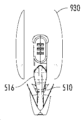
예를 들어, 도 47a ~ 도 47e에 도시된 것과 같은 일부 실시예에서, 여성의 면도기가 도시되어 있으며, 다른 구성보다 큰 헤드 부분을 특징으로 한다. 더 큰 헤드 카트리지(300)는 양면 면도기를 생성하는 카트리지의 2개의 동일한 측면을 가지지만, 상이한 측면이거나 상이한 기능을 가질 수 있다. 예를 들어, 일 측면은 현재 또는 미래에 개발될 것을 포함하는, 보습 스트립 또는 면도 크림 로션 또는 첨가제가 포함된 사전 면도 측면(pre shaving side)이 될 수 있으며, 다른 측면은 면도를 위해 사용될 수 있다. 대안으로, 일 측면에 하나의 블레이드를 가질 수 있으며 다른 측면에는 다른 개수의 블레이드를 가질 수 있다. 일부 실시예에서, 한 측면은 큰 둥근 카트리지 헤드를 가질 수 있고 다른 측면은 큰 둥근 카트리지(300) 헤드를 갖지 않을 수도 있으며, 대신에 본원에서 이미 설명된 것과 같은 표준 카트리지 헤드를 가질 수 있다. 이러한 실시예에서, 한쪽은 남성용으로, 다른 쪽은 여성용으로 사용할 수 있으며, 여행용으로 유용하다.For example, in some embodiments, such as those shown in Figures 47A-47E, a woman's razor is shown, featuring a larger head portion than other configurations. The
여성의 큰 둥근 카트리지 헤드는 임의의 형상 또는 크기일 수 있다. 일부 실시예에서, 본원에 설명된 정상 카트리지 헤드는 도면에 도시된 것과 같은 외부 둥근 카트리지 헤드 조립체(930)에 연결될 수 있다. 이러한 외측 둥근 헤드 조립체(930)는 임의의 형상 또는 외형 또는 임의의 수의 표면을 가질 수 있으며, 하나 내지 임의의 수의 부품들, 임의의 수의 피스들 및 임의의 유형의 재료를 가질 수 있다. 설명된 카트리지 헤드는 임의의 수의 고무 패드, 보습 저장 부 및 보습 스트립, 또는 현재 알려진 또는 임의의 유형의 면도기 카트리지 부품을 가질 수 있다. 외부 주변(932)은 임의의 모양, 임의의 각도 또는 크기 일 수 있거나 임의의 두께 일 수 있다. 조립체(930)는 임의의 측면 또는 부분이 면도에 사용되는 동안 임의의 측면 또는 부분이 내부, 외부 또는 임의의 방향으로 굴곡(flex)될 수 있고, 사용자 피부의 윤곽을 따라가는 경우에 면도기의 임의의 부분은 임의의 방향으로 굴곡될 수 있다.The female large round cartridge head can be of any shape or size. In some embodiments, the normal cartridge head described herein may be connected to an external round
더 큰 카트리지 헤드는 굴곡 블레이드를 가질 수 있으며, 카트리지의 양 측면상의 블레이드의 임의의 부분이 굴곡되며, 면도되는 면도 각도에 따라 블레이드의 양 측면이 임의의 방향으로 굴곡되거나 벤딩되거나 또는 벤딩되거나 굴곡될 수 있다.Larger cartridge heads may have curved blades, where any portion of the blade on either side of the cartridge is curved, and depending on the shaving angle being shaved, both sides of the blade may be curved or bent in any direction or may be bent or curved. You can.
조립체(930)의 두면은 카트리지의 일부일 수 있거나 별도의 부품 또는 피스 일 수 있다. 주 카트리지 바디에서 분리되고 주 카트리지 바디에 조립되는 경우, 카트리지 바디 및 조립체는 영구적 또는 비-영구적 연결로 구현될 수 있다. 예를 들어, 조립체(930)는 영구적 스냅 또는 연결 또는 현재 알려진 또는 미래에 개발될 방법에 의해 주 카트리지 바디에 부착될 수 있다. 여성의 큰 헤드는 큰 헤드 내에 둘러싸인 단부 캡(934)을 가질 수 있거나 또는 카트리지 헤드와 분리될 수 있다. 조립체(930)가 연결되면, 카트리지의 일부를 클램 쉘(clamshell)로 둘러쌀 수 있도록 연결될 수 있으며, 이는 단부 캡(934)을 둘러 싸서 부착될 때 영구적인 연결을 형성하고 조립체(930)로부터 분리될 수 없도록 한다.The two sides of
조립체(930)는 수형 또는 암형 연결들과 같은 연결 지점(936)을 가질 수 있고 주 카트리지 바디 상에 상응하는 반대 연결을 가질 수 있다. 연결은 여러 가지 방법, 초음파 용접 또는 다른 많은 방법으로 이루어질 수 있으며 조립체(930)는 현재 알려졌거나 미래에 개발될 여러 가지 방법으로 비 영구적으로 또는 영구적으로 부착될 수 있다. 카트리지와 더 큰 둥근 헤드 조립체(930) 사이의 임의의 부분 또는 영역은 연결들을 가질 수 있고, 조립체(930)가 주 카트리지 바디를 함께 둘러싸고 보유하도록 구성될 수 있다.The
도 47a에 도시된 바와 같이, 더 큰 둥근 헤드 카트리지 바디의 하단 영역은 고무 패드 또는 보습 스트립을 가질 수 있고, 큰 둥근 섹션을 가질 수 없고, 모든 다른 측면보다 적은 단지 작은 부분이다. 대부분의 여성용 둥근 면도기는 일반적으로 둥글고 보습 스트립과 패드가 있는 블레이드들의 하단 부분을 넘어 확장되는 하단 영역을 가지고 있다.As shown in Figure 47A, the bottom area of the larger round head cartridge body can have a rubber pad or moisturizing strip and cannot have a large round section, only a small portion less than all other sides. Most women's round razors have a bottom area that extends beyond the bottom of the blades, which is generally round and has a moisturizing strip and pad.
도시된 더 큰 둥근 헤드는 누락된 하단-둥근 부분을 가지고, 따라서 하단은 둥근 부분과 평행하지 않다. 이러한 구성은 스위블 암(swivel arm)이 연결되고 적절하게 기능할 수 있게 하여 사용자가 측면을 전환하여 면도기를 카트리지의 제2 면도 측면 또는 다른 측면으로 뒤집을 수 있다.The larger round head shown has a missing bottom-round portion, so the bottom is not parallel to the round portion. This configuration allows the swivel arm to connect and function properly, allowing the user to switch sides and flip the razor to the second shaving side of the cartridge or the other side.
도시된 더 큰 둥근 헤드는 둥근 형태 또는 임의의 모양 또는 크기 일 수 있는 평평한 상부(938)의 외부 주변(938)을 가지며, 카트리지의 양 단부를 향해 연장되고, 이후 둥근 형태로 스위블 암을 향해 하향 연장되어 정지되므로 카트리지 최 하단 최 외곽 부분 주변과 스위블 암 사이에 갭이 있게 되고, 카트리지 주 몸체를 향해 위쪽을 향해 각도를 갖는다. 각도 또는 갭(940)은 스위블 암(510)의 형상에 의존한다. 이러한 갭(940)은 카트리지가 문제 없이 앞뒤로 용이하게 스위블 할 수 있게 하고 사용자가 측면을 카트리지의 제 2 면도 측면으로 전환할 수 있게 하기 때문에 조립체에 필수적이다. 이러한 갭(940)은 또한 스위블 암이 카트리지에 연결되고 앞뒤로 자유롭게 스위블 할 수 있게 한다.The larger round head shown has an
도면은 더 큰 둥근 헤드 및 카트리지 홀더에 대해 2개의 피스를 도시하지만, 하나 내지 임의의 수의 피스가 존재할 수 있다. 도면은 또한 조립된 카트리지 주 바디가 조립체(930)의 내부의 부분 또는 홈(groove) 또는 공동(cavity)에 위치될 수 있고, 여성의 큰 헤드의 나머지 절반이 노출된 카트리지와 카트리지 단부를 통해 배치됨을 또한 보여준다. 두 개의 큰 둥근 헤드와 홀더 피스는 이후 스내핑 되거나 초음파 용접되거나 또는 현재 알려진 또는 미래에 개발될 일부 다른 방법으로 연결된다. 도면은 조립체(930)가 카트리지에 부착되는 한 방법을 나타내지만, 조립체(930)가 실제 카트리지 구조의 일부일 수 있고, 영구적으로 또는 비-영구적으로 부착되거나 함께 성형될 수 있음을 알 수 있다.The drawing shows two pieces for the larger round head and cartridge holder, but there may be one to any number of pieces. The diagram also shows that the assembled cartridge main body may be positioned in a groove or cavity within the interior of
도 47d에 도시된 바와 같이, 조립체(930)의 내부 부분은, 조립되는 경우에, 카트리지(300)에 고정하기 위하여 공동(936)을 제공한다. 조립체의 측면은 단부 캡(900)으로 더 동작하고, 제1 경사 표면(942) 및 제2 경사 표면(942)을 더 포함한다. 조립체(930)의 다양한 구성 요소는 도 46과 관련하여 후술되는 것과 유사하게 기능한다. 이와 같이, 제1 경사 표면(942) 및 제2 경사 표면(944)은 스위블 암(510)의 맞물림 부(516)와 접촉한다.As shown in Figure 47D, the interior portion of
일부 실시예에서, 카트리지 헤드는 상이한 구성으로 제공될 수 있다. 예를 들어, 카트리지 헤드는 삼각형 모양 일 수 있다. 그러한 실시예에서, 면도기 카트리지의 상부는 삼각형 카트리지의 상부이다. 삼각형의 각각의 면에는 앞서 설명한 바와 같이 블레이드, 고무 패드 및 보습 스트립을 갖는 면도 표면이 있다. 삼각형의 하단은 핸들이 삼각형 카트리지에 연결되는 곳이다. 핸들 및 삼각형 카트리지 연결은 이러한 애플리케이션에서 언급되었거나 현재 또는 미래에 개발된 모든 연결 일 수 있다. 이러한 삼각형 카트리지로 핸들은 임의의 핸들 모양 또는 디자인이 될 수 있다. 이러한 핸들은 핸들의 각각의 면이 동일한 디자인이고, 제1 면도 측면 또는 제2 면도 측면을 면도하는 경우에 손에 편안하게 피팅될 수 있도록 디자인될 수 있다. 이러한 디자인을 이용하여, 핸들을 카트리지에 연결하고 양면 면도기의 일 측면만을 면도하면 되고, 제1 측면이 둔해지면(dull), 단순히 전체 핸들과 카트리지를 완전히 회전시켜 돌리고 삼각형 카트리지의 제2 면도 측면을 사용하여 면도를 시작하기만 하면 된다. 사용자는 제1 면도 측면에서 제2 면도 측면으로 전환하는 경우에 카트리지를 분리할 필요가 없다. 삼각형 면도 측면의 각도는 면도를 위한 완벽한 각도일 수 있다. 삼각형 측면은 서로를 향해 안쪽으로 (삼각형의 중간 쪽으로) 굴곡될 수 있어, 사용자가 보다 편한 면도를 할 수 있다. 굴곡을 방지하거나 원하는 각도 내에서 굴곡을 제한하는 정지부가 있을 수 있다. 삼각형의 상부는 플렉스 힌지를 가질 수 있으므로 양면 삼각형 면도기의 면도 표면이 서로를 향해 안쪽으로 굴곡될 수 있다.In some embodiments, cartridge heads may be provided in different configurations. For example, the cartridge head may be triangular in shape. In such an embodiment, the top of the razor cartridge is the top of a triangular cartridge. Each side of the triangle has a shaving surface with a blade, rubber pad, and moisturizing strip as previously described. The bottom of the triangle is where the handle connects to the triangle cartridge. The handle and triangle cartridge connections may be any connection mentioned in these applications or developed now or in the future. With these triangular cartridges, the handle can be any handle shape or design. These handles can be designed so that each side of the handle has the same design and fits comfortably in the hand when shaving either the first shaving side or the second shaving side. With this design, you only need to attach the handle to the cartridge and shave one side of the double-sided razor, and when the first side is dull, simply rotate the entire handle and cartridge to a full rotation and shave the second shaving side of the triangular cartridge. Just use it and start shaving. The user does not need to remove the cartridge when switching from the first shaving side to the second shaving side. The angle of the triangular shave side may be the perfect angle for shaving. The sides of the triangle can bend inward toward each other (toward the middle of the triangle), allowing the user to shave more comfortably. There may be stops that prevent bending or limit bending within a desired angle. The top of the triangle may have a flex hinge so that the shaving surfaces of the double-sided triangular razor can bend inward towards each other.
일 실시예에서 카트리지의 제조 및 블레이드의 효율적인 조립을 용이하게 하기 위해 제1 및 제2 면도 영역(330, 370) 사이에 단일 블레이드가 연장되는 것이 선호되는 반면에, 그러한 배치가 더 복잡한 제조와 연관되더라도 개별 블레이드는 각 면도 영역을 채운다. 또한, 특정 실시예에서, 도 39a ~ 도 39b에 도시된 바와 같이, 각 면도 영역은 다른 개수의 면도 블레이드에 의해 점유되어 하나의 면도 영역이 다른 면도 영역보다 더 많은 노출된 블레이드를 가지며, 그 역도 성립한다.While in one embodiment it is preferred to have a single blade extending between the first and
블레이드(400)는 현재 공지되거나 이후 개발될 다양한 제조 방법을 사용하여 카트리지(300) 내에 적층된, 이격된 관계로 고정될 수 있다. 도 15에 도시된 바람직한 실시예에서, 블레이드 단부(415 ~ 435)는 각각 제1 측면 및 제2 측면 하우징(312, 352)에 형성된 슬롯(315, 355) 사이에서 캡쳐된다. 도 17에 도시된 다른 실시예에서, 블레이드(400b)는 포지셔닝 스파인(460b)을 따라 정렬되고, 스파인(460b)에 고정되고 블레이드(400b) 사이로 연장되는 스페이서 요소(465b)를 사용하여 이격된다. 이러한 대안적인 실시예에서, 카트리지(300b) 내에서 블레이드(400b)를 또한 지지하기 위해 블레이드 단부(415b)를 캡쳐하는 슬롯(315b, 355b)이 또한 하우징(312b, 322b)에 제공될 수 있다. 특정 실시예에서, 포지셔닝 스파인은 스페이서 요소와 조합하여 사용되거나 또는 사용되지 않을 수도 있고, 또는 스페이서 요소는 선택적 일 수 있다. 또한, 스페이서 요소는 개별 블레이드 구성을 변경시키기 위해 높이 또는 두께가 변할 수 있다.The blades 400 may be secured in a stacked, spaced apart relationship within the
블레이드(400)는 다양한 제조 방법을 이용하여 형성될 수 있으며, 현재 공지되거나 이후에 개발될 임의의 형상, 디자인, 재료, 조성 또는 구성일 수 있다. 도 15를 참조하면, 논의의 기저로서 블레이드(410)를 사용하고, 일 실시예에서, 블레이드가 카트리지(300)내에 위치되는 경우에 블레이드(410)는 각각이 블레이드 중심 축(413)에 대해 각을 이루는 하향 구성으로 배향된 블레이드 에지(412, 414)를 갖는 단일 피스의 금속 또는 다른 재료이고, 여기서 금속 또는 다른 재료의 단일 피스는 공지된 또는 이후에 개발될 제조 방법을 이용하는 형상으로 스탬핑되거나 다르게 성형될 수 있다. 블레이드 에지(412, 414)의 각도 배향은 사용자에게 밀착되고 편안하고 효과적인 면도를 제공하도록 구성된다. 도 18a-18b에 도시된 다른 실시예에서, 블레이드(410c)는 복수의 요소에서 형성될 수 있고, 여기서 블레이드 에지 블레이드(412c, 414c)는 용접부(416c)에서 지지체 캐리어(411c) 상에 고정되고, 복수의 블레이드(410c), 각각은 캐리어(411c) 및 에지 피스(412c, 414c)을 포함하고, 이격된 관계로 적층된다. 지지 캐리어(411c) 및/또는 에지 피스(412c, 414c)는 임의의 형상, 디자인, 재료, 조성 또는 구성 일 수 있다. 도 18c는 3 개의 적층된 블레이드(410c)를 갖는 카트리지(300c1)를 도시하고, 도 18d는 5 개의 적층 블레이드(410c)를 갖는 카트리지(300c2)를 도시한다. 임의의 수의 블레이드가 카트리지 내에 조립될 수 있다. 지지 캐리어(411c)는 블레이드(410c) 전체에 구조적 안정성을 부여하고 에지 피스(412c, 414c)는 사용 중에 구부리거나, 굴곡되거나, 또는 그렇지 않으면 움직이지 않도록 유지한다.Blade 400 may be formed using a variety of manufacturing methods and may be of any shape, design, material, composition or configuration currently known or later developed. 15 , using the blades 410 as the basis of discussion, in one embodiment, when the blades are positioned within the
도 19a에 도시된 또 다른 실시예에서, 면도기 카트리지(300d)는 블레이드(400d)의 중심 축(413d)에 대해 대향-배향된 블레이드 에지(412d, 414d)를 갖는 블레이드(400d)를 포함한다. 도 19b에 도시된 또 다른 실시예에서, 도 19B에서, 면도기 카트리지(300e)는 중심 축(413e)에 대해 대향-배향된 블레이드 에지(412e, 414e)를 갖는 대각 블레이드(400e)를 포함한다. 도 19a ~ 도 19b의 실시예에서, 카트리지(300d, 300e)는 전형적으로 카트리지(300d, 300e)의 어느 한 측면을 사용하여 면도를 용이하게 하기 위해 블레이드의 중심 축(413d, 413e)을 따라 뒤집어질 수 있다.In another embodiment shown in FIG. 19A , razor cartridge 300d includes a blade 400d with blade edges 412d and 414d that are opposed-oriented with respect to a central axis 413d of blade 400d. In another embodiment shown in FIG. 19B, the razor cartridge 300e includes a diagonal blade 400e with blade edges 412e and 414e opposed-oriented about a central axis 413e. 19A-19B, the cartridges 300d, 300e are typically flipped along the central axis 413d, 413e of the blade to facilitate shaving using either side of the cartridge 300d, 300e. You can lose.
설명된 임의의 구성에서, 블레이드는 면도에 적합한 접근 각도로 구현될 수 있다. 그러한 각은 60도일 수 있거나 선호에 따라 임의의 각도일 수 있다. 예를 들어, 일부 구성에서는 사용자가 블레이드를 조정할 수 있다. 다른 각도 방향, 치수 및 구성이 가능하다. 또한, 블레이드는 카트리지 내의 임의의 형상, 디자인, 두께, 치수, 중량, 구조, 구성, 각도 위치, 또는 이들의 조합 일 수 있다.In any of the configurations described, the blade may be implemented at an approach angle suitable for shaving. Such angle may be 60 degrees or may be any angle depending on preference. For example, some configurations allow the user to adjust the blades. Other angular directions, dimensions and configurations are possible. Additionally, the blades may be of any shape, design, thickness, dimension, weight, structure, configuration, angular position, or combination thereof within the cartridge.
일부 실시예에서, 블레이드 자체는 굴곡 블레이드(flex blade)이고, 카트리지의 양 측면상의 블레이드의 임의의 부분은 면도되는 면도 각도에 따라 임의의 방향으로 굴곡되거나 또는 벤딩될 수 있다. 각각의 블레이드는 면도기 카트리지가 윤곽 또는 고르지 않은 표면을 통과하는 경우에 또는 독립적으로 또는 동시에 굴곡될 수 있다. 일부 실시예에서, 카트리지 바디 또는 블레이드의 일부는 면도하는 동안 굴곡되거나 벤딩될 수 있다. 양면 면도기의 각각의 면은 바디를 가질 수 있거나 면도날이 임의의 방향으로 굴곡되거나 각각의 면이 블레이드 또는 바디에 다른 굴곡 지점을 가질 수 있다. 일부 실시예에서, 일 측면은 굴곡 또는 이동 블레이드를 가질 수 있고 다른 측면은 전혀 가질 수 없다.In some embodiments, the blade itself is a flex blade, and any portion of the blade on either side of the cartridge can flex or bend in any direction depending on the shaving angle at which it is shaved. Each blade may be bent independently or simultaneously as the razor cartridge passes over a contour or uneven surface. In some embodiments, a portion of the cartridge body or blade may be curved or bent during shaving. Each side of a double-sided razor can have a body or the blade can be bent in any direction or each side can have a different bend point on the blade or body. In some embodiments, one side may have curved or moving blades and the other side may not have any.
이제 카트리지(300)(도 14a ~ 도 15)로 돌아 가면, 상부 패드 영역(320, 360)에는 바람직하게는 윤활 스트립, 보습 스트립, 수화 젤, 크림, 비타민, 물 활성화 제품, 보습제 등과 같은 면도 개선제 또는 촉진제를 갖는 전달 시스템(322, 362)이 제공된다. 스트립의 성질을 갖는 전달 시스템(322, 362)이 설명되었지만, 현재 공지되거나 이후에 개발되는 스트립 이외의 전달 시스템이 이용될 수 있음을 이해할 것이다. 또한, 상부 패드 영역들(320, 360)은 이러한 영역들(320, 360)이 사용자의 피부와 블레이드(400)의 결합을 따르는 경우에 가장 흔한 위치에 있음에도 불구하고, 원한다면 전달 시스템(322, 362)은 상부 패드 영역들(320, 360) 내부가 아닌 다른 곳에 배치될 수 있으므로, 이러한 전달 시스템(322, 362)은 피부 주변을 스크랩하여 발생하는 민감도 및 자극에 대처하기 위해 피부에 치유 또는 진정 효과를 제공하는 경향이 있다. 전달 시스템(322, 362)은 단부 캡(390) 사이에서 또는 면도 표면상의 임의의 위치에서 연장되는 스트립의 형태 일 수 있거나, 또는 상이한 형상 또는 다양한 형상을 가질 수 있거나, 또는 텍스처를 사용하거나 그렇지 않으면 피부에 긍정적인 표면 피처를 가질 수 있다. 또한, 전달 시스템(322, 362)은 제조 공정 중에 하우징(312, 352)(도 15) 내부에 형성될 수 있거나, 또는 접착제, 프레스 핏, 성형 또는 다른 방식으로 하우징(312, 352)에 적용될 수 있다. 또한, 전달 시스템(322, 362)은 하우징(312, 352)에 통합되거나, 필요에 따라 제거 가능하고 교체 가능할 수 있다.Now returning to cartridge 300 (FIGS. 14A-15),
일부 실시예에서, 면도기가 사용될 때 노출될 수 있는 물, 비누, 면도 크림 또는 겔 또는 임의의 물질로부터 보습 스트립을 보호할 수 있도록 코팅이 보습 스트립에 도포될 수 있다. 그러한 방법으로 스트립으로부터 보습제를 분배하거나 방출하는 유일한 방법은 스트립이 실제로 사용되고 보습 스트립의 표면이 피부와 같은 다른 표면에 문질러지는 경우이다. 이는 사용될 때까지 양면 면도 블레이드의 제2면도 측면의 보습 스트립을 보호한다.In some embodiments, a coating may be applied to the moisturizing strip to protect the moisturizing strip from water, soap, shaving cream or gel, or any substance to which it may be exposed when the razor is used. The only way to dispense or release moisturizer from a strip in such a way is if the strip is actually used and the surface of the moisturizing strip is rubbed against another surface, such as the skin. This protects the moisturizing strip on the second side of the double-sided shaving blade until it is used.
하부 패드 영역(340, 380)에는 바람직하게는 제1 및 제2 면도 영역(330, 370)에 의한 결합 전에 면도 표면을 준비하도록 구성된 파지 패드(342, 382)가 제공된다. 일 실시예에서, 파지 패드(342, 382)는 더 밀착된 면도를 제공하기 위해 피부를 스트레치하는 이격된 핀(fin)에서 형성된다. 매끄러운 표면을 갖는 파지 패드를 포함하여, 현재 공지되거나 이후 개발되는 상이한 형상, 구성, 텍스쳐 및 구성을 갖는 패드의 다른 구성도 가능하다. 대안적으로, 하부 패드 영역들(340, 380)은 파지 관계 이외의 방식으로 피부와 결합하도록 구성되거나 핸들(100)와 같은 면도기(50)의 다른 측면들과 결합하도록 구성된 소정의 피처들과 함께 제공될 수 있다.The
바람직한 실시예에서, 각각의 하부 패드 영역(340, 380)에는 후술되는 바와 같이 푸쉬 핀(240)의 가이드 팁(248)과 결합하기 위한 제1 및 제2 궤적(344, 384)이 각각 제공된다. 인터럽트(394)는 각 궤적(344, 384)의 종단에 형성되고 카트리지(300)의 제1 측면(310)과 제2 측면(350) 사이의 변곡점(point of inflection)을 규정한다. 여기서 설명하는 바와 같이, 면도기(50)의 정상적인 사용 동안에 인터럽트(394)는 제1 및 제2 면도 측면들(310, 350) 사이에서 카트리지(300)의 부주의한 전환을 방지한다. 궤적(344, 384) 및 인터럽트(394)는 하부 패드 영역들(340, 380)과 일체로 형성될 수 있다. 대안적으로, 도 15에 도시된 일 실시예에서, 제1 암(396), 제2 암(396), 및 이들 사이에 형성된 인터럽트(398)을 갖는 분리된 궤적 부재(395)가 카트리지(300)에 부착되어, 제1 암(396)은 궤적(344)을 형성하고, 제2 암(396)은 궤적(384)를 형성하고, 궤적(344, 384)의 연장은 인터럽트(394)를 형성한다. 아래에서 더 상세히 설명하는 바와 같이, 사용자가 제2 측면(350)을 이용하여 면도하는 동안에, 푸쉬 핀(240)의 가이드 팁(248)은 제1 궤적(344)을 따라 이동하고, 사용자가 제1 측면(310)을 이용하여 면도하는 동안에, 푸쉬 핀(240)의 가이드 팁(248)은 제2 궤적(384)을 따라 이동하고, 인터럽트(394)는 면도기(50)의 정상적인 사용 중에, 가이드 팁(248)이 제1 궤적(344)에서 제2 궤적(384)으로 교차하는 것을 방지하고, 그 역도 성립한다.In a preferred embodiment, each
인터럽트(394)는 전형적으로 궤적(344, 384)의 연장이지만, 임의의 크기 또는 형상 일 수 있고 임의의 재료로 만들어질 수 있음을 이해할 것이다. 일부 실시예에서, 인터럽트(394)의 형상은 스위블 암(510)에 대한 카트리지(300)의 시작 각도를 지시하도록 구성될 수 있다.Interrupt 394 is typically an extension of
하부 패드 영역(340, 380)의 단부에는 핸들(100)을 통해 커넥터 구조(200)와 카트리지(300) 사이에서 인터페이스 되는 스위블 암 연결(500)(도 20 ~ 도 20g 및 도 21a ~ 도 21c)과의 결합을 위한 스위블 암 결합 캠 표면(348) 및 카트리지(300)의 특정 에지 영역을 따라 스위블 암 결합 개구(346)(도 14d 및 도 14f)가 제공된다. 스위블 암 개구(346)가 카트리지(300)의 특정 에지 위치에서 도시되는 반면에, 개구(346)는 카트리지(300)의 어는 곳에나 위치될 수 있고, 유사하게 스위블 암(510)이 이들이 배치되는 어디든지 개구와 결합되도록 구성될 수 있음을 이해할 것이다. 도시된 바와 같은 일 실시예에서, 개구(346)는 제1 및 제2 면도 영역(310, 370)과 독립적으로, 그리고 단부 캡(390)과 독립적으로 카트리지(300)의 에지를 따라 배치된다. 다른 실시예에서, 개구(346)는 단부 캡 또는 다른 위치에 위치될 수 있다. 스위블 암 연결(500)은 복수의 스위블 암(510)을 포함하고, 이들 상이에 형성된 연결 바디(530)를 더 포함한다. 스위블 암(510)은 카트리지(300)를 스위블 암 연결(500)과 강제 결합시킬 때, 카트리지(300)상의 캠 표면(348)에 충돌하는 캠 표면(514)을 갖는 결합 핀(512)을 더 포함하고, 이는 결합 핀(512)이 스위블 암 결합 개구(346)로 진입하는 것을 가능하게 하기 위해 스위블 암(510)이 외부로 굴곡되도록 유도하고(도 21b), 이때 스위블 암(510)은 다시 굴곡지게 되고(도 21c), 스위블 암 결합 개구(346) 내에 결합 핀(512)이 고정되도록 유지한다. 반면에 개구가 하부 패드 영역 및 이동 궤적에 인접한 것으로 도시되는 동안, 개구는 카트리지 상의 다른 위치에 있을 수 있음을 이해할 것이다. 또한, 결합 핀(514)은 한 번에 하나씩 스위블 암 결합 개구(346)에 삽입될 수 있고, 캠 표면(514, 348)의 보조를 통해 개구(346)와 결합 및/또는 분리될 수 있다. 예를 들어, 하나의 핀(514)이 캠 표면(348, 514)의 보조 없이 하나의 개구(346) 내로 삽입될 수 있고, 다른 핀은 캠 표면을 사용하여 스위블 암을 외부로 스트레치하는 것에 의해 다른 개구에 삽입될 수 있거나, 또는 수동으로 스위블 암을 외부로 스트레치 한 이후 캠 표면을 보조하거나 또는 보조하지 않고 핀을 개구 내부로 하강(drop)시킬 수 있다. 일 실시예에서, 스위블 암 연결(500)은 핸들(100)에 영구적으로 부착되고 사용자는 스위블 암으로부터 카트리지(300)를 분리하고 축 주위로 카트리지를 뒤집어 스위블 암에 카트리지를 재-부착시킴으로써 카트리지 측면들 간을 전환해야 하고, 이는 사용자가 카트리지의 한 면을 이용하여 면도하는 것을 완료하고, 카트리지의 다른 면을 이용하여 면도하기를 원하는 경우에 발생할 것이다. 본 명세서에 설명된 다른 실시예에서, 일단 카트리지(300)가 조립체(600)를 형성하도록 스위블 암 연결(500)에 조립되면, 제조 시점에서 또는 사용자에 의해 발생될 지라도, 카트리지(300)가 정상적인 사용 중에 스위블 암 연결(500)에서 제거되지 않도록 구성된다. 특정 실시예에서, 카트리지(300)와 스위블 암 연결(500) 사이의 연결은 정상적인 사용 중에 제거 가능하도록 구성되는 반면, 다른 실시예에서는 정상적인 사용 중에 더 영구적 또는 반-영구적으로 구성된다.At the ends of the
본원에 도시되고 설명된 실시예가 스위블 암(510)에 의존하지만, 카트리지(300)의 기울임을 제어하고 제한하는 중앙 연결 부와 결합된 푸쉬 핀 조립체에 의존하는 다른 실시예가 고려될 수 있음을 이해할 것이다.Although the embodiments shown and described herein rely on a
커넥터 구조(200)를 통해 이루어질 수 있는 핸들(100)과 카트리지(300) 사이의 연결은 리세스될 수 있거나 또는 카트리지의 면도 표면과 함께 리세스될 수도 있다. 상기 연결은 카트리지(300)의 최하부 중간 영역에 있을 수 있거나, 또는 이는 결합 개구(346)에 대해 도시된 바와 같은 카트리지의 최하부 영역의 에지 주변, 또는 임의의 다른 위치에 있을 수 있다. 상기 연결은 보습 스트립과 같은, 카트리지(300)의 다른 피처에 의해 둘러싸일 수 있고, 상기 연결은 도시되고 설명된 바와 같은 스위블 연결을 초래할 수 있거나, 또는 이는 고정 연결을 통해 이루어질 수 있다.The connection between the
바람직한 실시예에서, 카트리지(300)와 스위블 암 연결(500)은 함께 결합되어 카트리지(300)를 핸들(100)과 결합시키기 전에 조립체(600)를 형성한다. 카트리지(300) 및 스위블 암 연결(500)의 조립은 제조 시점과 같이, 사용자에게 배포되기 이전에 발생한다. 일 실시예에서, 카트리지(300) 및 스위블 암 연결(500)은 각각 동일한 제조 설비에서 제조된 다음 함께 결합된다. 또 다른 실시예에서, 카트리지(300) 및 스위블 암 연결(500)은 각각 상이한 설비에서 제조된 다음 설비 중 하나에서 함께 결합된다. 또 다른 실시예에서, 카트리지(300) 및 스위블 암 연결(500)은 각각 다른 설비에서 제조된 다음 완전히 다른 설비에서 함께 결합된다. 또한, 다수의 조립체(600)는 사용자에게 분배하기 위해 멀티-팩(도시되지 않음)으로 함께 판매될 수 있거나, 또는 사용자가 조립체(600)를 형성하도록 스위블 암 연결(500)에 카트리지(300)를 함께 연결할 수 있고, 이후에 조립체(600)를 핸들(100)에 고정시킬 수 있다.In a preferred embodiment,
스위블 암(510, 520)은 스위블 암 연결(500)의 스위블 암(510)을 파지하기 위한 다양한 옵션을 사용자 (미도시)에게 제공하는 파지 부(518)를 더 제공한다. 파지 부(518)는 핸들(100) 하부로 또는 이를 향해 스위블 암(510)을 푸쉬하기 위한 임의의 형상을 갖는 상부 슬로프(517), 및 핸들(100) 상부로 또는 이로부터 이격되게 스위블 암(510)을 푸쉬하기 위한 임의의 형상을 갖는 하부 슬로프를 가지고, 스위블 암의 상부 및 하부 슬로프는 각각의 슬로프가 파지 및 결합되기에 용이하고 편리하도록 사용자의 손가락에 편안하게 피팅되도록 형성되고 구성된다. 예를 들어, 후술하는 바와 같이 조립체(600)를 핸들(100)에 부착하는 것이 바람직하다면, 사용자는 파지 암(510)을 통해 파지 부(518)의 상부 경사 표면(517)을 주로 결합시키고, 동시에 핸들(100)에 대해 조립체(600)의 푸싱 모션에 참여하고 푸싱 레버리지를 형성하기 위해 카트리지(300)의 단부 캡(390)을 통해 파지 표면(392)을 결합하기 위해 조립체(600)를 파지하고자 할 수 있다(도 22a 내지 도 22b). 조립체(600)를 핸들(100)에 대해 상향으로 당김으로써 커넥터 구조(200)로부터 조립체(600)를 분리하는 것이 바람직하다면, 버튼(210)이 상향으로 프레스 되는 동안 조립체(600)(도 23a ~ 도 23b) 상에 인장력을 제공하기 위해 사용자는 대신에 스위블 암(510)의 파지 부(518)의 하부 슬로프 및 가능하게는 단부 캡(390)을 파지하고자 할 수 있다. 도 23c에 도시된 다른 실시예에서, 버튼의 이동으로 인해 핸들에서 카트리지 및 스위블 암 연결 조립체의 해제로 전환되기만 하면, 버튼은 측 방향(도 23c) 또는 하측(미도시)과 같은 상향 이외의 방향으로 이동될 수 있다. 카트리지 및 스위블 암은 소비자가 연결 및 분리할 수 있는 임의의 방법으로 고정될 수 있다.The
도 23d에 도시된 또 다른 실시예에서, 어떠한 버튼도 필요하지 않고, 조립체(600)는 자기 커넥터(560)에 의해 대응하는 커넥터 구조에 결합된다. 이러한 자기 커넥터(560)는 다른 실시예와 관련하여 논의된 커넥터(540)과 유사하게, 후드 상에 (도 11b ~ 도 11c 등 참조) 또는 스위블 암, 핸들 연결 또는 카트리지의 임의 위치에 있을 수 있다. 따라서, 조립체를 분리하기 위해, 사용자는 스위블 암(510)의 파지 부(518)의 하부 슬로프를 파지하고, 자기 커넥터(560)에서의 자기력을 극복하기에 충분한 인장력을 조립체(600)에 인가할 수 있다. 이러한 자기 연결은 신속한 전환을 허용하며, 예를 들어 면도 중일 때와 같이 고정밀도가 불가능한 경우 사용자가 구성을 전환할 수 있도록 한다. 자성 재료는 핸들에 일체형으로 제공되어 스위블 암 연결(500)상의 자기 커넥터(560)와 함께 결합되거나 또는 임의의 위치와 결합할 수 있다. 대안적으로, 자기 연결은 핸들을 통해 존재할 수 있고 스위블 암 커넥터는 자성 재료로 형성될 수 있고, 그 역도 성립하거나, 또는 동일한 조합으로 형성될 수 있다. 또한, 자기 요소가 면도기의 다른 위치에 있을 수 있다. 또한, 이러한 연결은 다른 실시예와 관련하여 전술한 다양한 복잡한 부분을 필요로 하지 않는다. 따라서, 이러한 연결은 자기 연결에 의해 강화된 간단한 슬라이딩 연결일 수 있으며, 다양한 형태로 제공될 수 있다.In another embodiment, shown in Figure 23D, no buttons are required and
다른 대안적인 실시예(도 23e ~ 도 23f)에서, 버튼(210)은 카트리지(300)를 스위블 암 연결(500)으로부터 분리시킬 수 있고, 스위블 암 연결(500)은 핸들(100)에 영구적으로 고정되거나 제거될 수 있다. 이어서, 스위블 암(510)을 수평 방향 외측으로 병진 이동시키기 위해 버튼을 위로 움직여, 그 사이에 보유된 카트리지(300)를 해제할 수 있다. 그런 다음 사용자는 카트리지를 뒤집거나 돌릴 수 있으며 카트리지의 다른 면도 측면을 사용할 수 있다. 버튼 또는 스위블 암(510)은 스프링이 로딩되어 버튼이 해제될 때 스위블 암(510)은 원위치로 내부로 전환될 수 있다. 대안적으로, 사용자(미도시)는 제1 방향으로 버튼을 이동시켜 스위블 암(510)을 바깥쪽으로, 제2 방향으로 이동시켜 스위블 암(510)을 내측으로 이동시킬 수 있다. 대안적으로, 사용자는 버튼을 사용하지 않고 스위블 암(510)으로부터 카트리지(300)를 해제할 수 있지만, 대신에 스위블 암(510)을 카트리지(300)로부터 잡아 당겨 스위블 암(510)으로부터 분리시킴으로써 카트리지(300)를 수동으로 해제할 수 있다.In another alternative embodiment (FIGS. 23E-23F),
맞닿음 부(516)는 또한 후술하는 바와 같이(도 28d에 도시) 카트리지(300)의 후방 회전 동안 단부 캡(390)의 이동에 대한 정지 부로서 동작함으로써 스위블 암 연결(500)에 대한 카트리지(300)의 과다-회전을 방지한다.The
스위블 암 연결(500)(도 20a 내지 도 20g)로 돌아가면, 연결 바디(530)는 중심 개구(534)를 갖는 상부 표면(532), 중앙 개구(534)와 각각의 측면 개구(536) 사이에 형성된 벽(538)을 갖는 중앙 개구(534)의 어느 한 측면상의 측면 개구(536), 결합 단부(140)와 연결 블록(250)의 상부 내부 벽(141) 사이에 형성된 갭(149)(도 11a)과 피팅되는 후드(540), 및 연결 블록(250)을 통해 스프링 암 릿지(270)와 결합하는 복수의 스프링 암(550)을 더 포함하고, 각각의 스프링 암 릿지(270)는 결합 캠 표면(272)과 분리 캠 표면(274)을 갖는다. 도 11b ~ 도 11c에 도시된 대안적인 실시예에서, 도 11a의 실시예에서 도시된 바와 같은 것 보다는 오히려, 수형 핸들 부(140a)를 수용하는 수형 연결(540a)로 다소 동작하기 위해 후드(540a)는 핸들의 결합 단부(140a) 위에 부착될 수 있고, 후드(540)는 결합 단부(140) 내에 수용된다. 도 24에 도시된 바와 같이, 스위블 암 연결(500)이 커넥터 구조체(200) 상에 하방으로 가압되는 경우에, 푸쉬 핀(240) 및 상부 연장 부(262)는 중앙 개구(534)를 통해 연장되고, 스프링 암(550)은 결합 캠 표면(272)과 결합하여 외부로 굴곡되고, 스프링 암(550)이 분리 캠 표면(274)에 대해 안착될 때까지 스프링 암 릿지(270) 주변을 이동하고, 스프링 암 릿지(270)는 스프링 암(550)과 벽(538) 사이에서 캡쳐된다. 스프링 암(550)이 분리 캠 표면(274)에 대해 안착되는 경우에, 스프링 암 릿지(270) 주위의 스프링 암(550)의 이동은 “클릭” 사운드 또는 촉각 감각을 발생할 수 있거나, 또는 주목할 만한 사운드 및/또는 촉각 감각이 없을 수 있다. 스위블 암 연결(500)을 커넥터 구조(200)에서 분리하고자 하는 경우에, 사용자는 단순히 버튼(210)과 버튼 암(214)을 위로 밀어 내고, 이는 버튼 릴리스 슬라이더(220)의 외부 암(225)을 통해 캠 단부 표면(226)이 스프링 암(550)에 대해 분리되도록 하고, 스프링 암 릿지(270)로부터 분리되어, 스위블 암 연결(500)이 커넥터 구조(200)에 대해 들어 올려지게 한다.Returning to the swivel arm connection 500 ( FIGS. 20A-20G ), the
일부 실시예에서, 중앙 개구(534)는 일 측면상에서 개방되어, 상부 표면(532)이 구조물의 일 측면에만 존재하도록 한다(도 20h ~ 도 20i). 이러한 실시예에서, 연결 바디(530)는 부가적인 유연성을 유지하고, 일단 클릭되면, 위치는 상부 표면(532)의 구조적인 지지 없이, 스프링 암(550)과 벽(538) 사이의 스프링 암 릿지(270)의 안착에 의해서만 유지된다. 따라서, 스프링 암 릿지(270)가 연결 바디(530)로부터 해제되도록 연결 바디(530)를 외부로 굴곡시켜 스위블 암 연결(500)이 반전될 수 있다.In some embodiments,
핸들(100)에 대한 카트리지(300)의 배향은 카트리지의 일 측면을 사용하여 면도하기 위한 제1 배향(610)(도 26a 내지 도 26b) 및 카트리지의 다른 측면을 사용하여 면도하기 위한 제2 배향(620)(도 27a 내지 도 27b) 사이에서 전환 가능하고 반전될 수 있다. 일 측면이 둔감해질 때 카트리지의 방향을 반전시키는 능력은 사용자가 카트리지(300)의 수명을 연장시키고 단일 카트리지(300)로부터 두 배의 수명을 효과적으로 얻게 한다. 일 실시예에서, 제1 방향(610)에서, 카트리지(300)의 제1 측면(310)과 제1 면도 영역(330)은 제1면도 영역(330)을 이용하여 면도하기 위하여, 핸들(100)을 통해 버튼(210)과 마주본다. 일 실시예에서, 제2 방향(620)에서, 카트리지(300)의 제2 측면(350)과 제2 면도 영역(370)은 제2 면도 영역(370)을 이용하여 면도하기 위하여, 핸들(100)을 통해 버튼(210)과 마주본다. 핸들(100)에 대한 카트리지(300)의 특정 방향으로 제1 및 제2 방향(610, 620)이 형성되는 반면에, 방향이 반전될 수 있거나, 또는 상이한 방향들이 동작 가능할 수 있다는 것을 이해할 것이다.The orientation of
카트리지(300)의 조립체(600)와 스위블 암 연결(500)이 핸들(100)로부터 분리된 상태로 유지되는 동안, 카트리지(300)는 스위블 암 연결에 대해 자유롭게 스윙될 수 있거나 또는 스위블 암은 스위블 암 결합 핀(512)과 스위블 암 결합 개구(346, 386)와의 결합을 가능하게 한다. 카트리지 및/또는 스위블 암은 임의의 각도 회전 및 한 측면에서 다른 측면까지 어느 정도의 각도로 서로에 대해 스윙할 수 있다. 카트리지는 한 측면에서 다른 측면으로 자유롭게 스윙할 수 있다. 조립체(600)가 핸들(100)에 연결될 때 카트리지(300)의 핸들(100)에 대한 방향이 결정되며, 이로써 푸쉬 핀(240)의 가이드 팁(248)은 연결 바디(530)의 중심 개구(534)를 통해 연장되고 스위블 암 연결(500)에 대한 카트리지(300)의 방향에 따라 제1 궤적(344) 또는 제2 궤적(384)과 결합된다. While the
조립체(600)가 카트리지(300)의 제1측면(310)과 제1 방향(610)(도26a ~ 도 26b)에 있고, 제1 면도 영역(330)이 핸들(100) 상의 버튼(210)과 마주보면, 카트리지(300)가 제1 면도 영역(330)을 따라 사용자 면도에 응답하여 피벗함에 따라 푸쉬 핀(240)의 가이드 팁(248)은 결합되고 하부 패드 영역(380) 상의 제2 궤적(384)을 따라 이동한다. 사용자가 제1 면도 영역(330)을 이용하여 면도함에 따라, 카트리지(300)는 완전히 직각 방향(612)(도 28a ~ 도 28b)에서 스위블 암 결합 핀을 따라 피벗하고, 여기서 푸쉬 핀(240)의 가이드 팁(248)은 완전히 회전된 방향(614)(도 28c ~ 도 28d)에서, 연결 블록(250)을 통해 상부 연장 부(262)의 상부 표면(263)과 맞물리기 위해 버튼(210) 및 인터럽트(394)로부터 카트리지(300)가 피벗하여 이격되게 하고, 여기서 푸쉬 핀(240)의 가이드 팁(248)은 약간 가압 해제되고, 스위블 암 연결(500)에 대해 카트리지(300)의 과도-회전을 방지하기 위해 단부 캡(390)은 스위블 암(510)에 대한 맞물림 부분(516)을 충격한다. 맞물림 부(516)를 충분히 충격할 만큼 카트리지(300)가 다시 피벗될 경우 맞물림 부(516)는 카트리지(300)의 전방 회전에 대한 정지 부로서 동작하고, 이는 정상적인 면도 동안 발생할 수도 있거나 또는 발생하지 않을 수 있다.The
유사하게, 조립체(600)가 카트리지(300)의 제2 측면(350)과 제2 방향(620)(도 27a ~ 도 27b)에 있고 제2 면도 영역(370)이 핸들(100) 상의 버튼(210)과 마주보면, 카트리지(300)가 제2 면도 영역(370)을 따라 사용자 면도에 응답하여 피벗함에 따라 푸쉬 핀(240)의 가이드 팁(248)은 결합되고 하부 패드 영역(380) 상의 제1 궤적(344)을 따라 이동한다. 사용자가 제2 면도 영역(370)을 이용하여 면도함에 따라, 카트리지(300)는 완전히 직각 방향(622)(도 29a ~ 도 29b)에서 스위블 암 결합 핀을 따라 피벗하고, 여기서 푸쉬 핀(240)의 가이드 팁(248)은 완전히 회전된 방향(624)(도 29c ~ 도 29d)에서, 연결 블록(250)을 통해 상부 연장 부(262)의 상부 표면(263)과 맞물리기 위해 버튼(210) 및 인터럽트(394)로부터 카트리지(300)가 피벗하여 이격되게 하고, 여기서 푸쉬 핀(240)의 가이드 팁(248)은 약간 가압 해제되고, 스위블 암 연결(500)에 대해 카트리지(300)의 과도-회전을 방지하기 위해 단부 캡(390)은 스위블 암(510)에 대한 맞물림 부분(516)을 충격한다. 맞물림 부(516)를 충분히 충격할 만큼 카트리지(300)가 다시 피벗될 경우 맞물림 부(516)는 카트리지(300)의 후방 회전에 대한 정지 부로서 동작하고, 이는 정상적인 면도 동안 발생할 수도 있거나 또는 발생하지 않을 수 있다.Similarly, the
따라서, 스위블 암(510)은 카트리지(300)의 단부 캡(390)을 지지하기 위한 맞물림 부(516)를 포함할 수 있다. 따라서, 사용자는 면도 중에 일정한 압력을 가할 수 있고, 카트리지(300)가 사용자의 얼굴에 적용될 것이다. 따라서, 카트리지(300)는 카트리지가 카트리지(300)에 충격을 가할 정도로 충분히 피벗된 경우 단부 캡(390)이 맞물림 부(516)와 접촉할 때까지 카트리지 헤드가 회전하기 때문에 카트리지 헤드의 이동 범위에 영향을 주지 않으면서 임의의 크기 또는 형상 일 수 있다. 맞물림 부(516)는 단부 캡(390)과 접촉하기 위한 임의의 수의 돌출 영역으로 구성될 수 있으며, 임의의 크기, 형상, 치수 및 위치 일 수 있다. 통상적으로, 총 4 개의 스위블 암(510) 상에 2개의 맞물림 부(516)가 있을 수 있다. 이로써, 맞물림 부(516)는 전방 및 후방 방향으로 독립적으로 위치될 수 있다. 맞물림 부(516)는 또한 각각의 스위블 암(510)상의 단일 부분일 수 있지만, 중간 부분이 제거되어 상승된 맞물림 부(516)를 구성하는 2개의 벽으로 된 부분이 생성된다. 맞물림 부는 임의의 크기 또는 형상일 수 있거나 바람직하게는 카트리지(300)를 균일하게 지지하기 위해 대칭인 것이 바람직하다. 상기 맞물림 부(516)는 바람직하게는 180도의 이동을 허용하도록 위치될 수 있거나 임의의 다른 각도의 회전을 허용할 수 있다.Accordingly, the
도 46a ~ 도 46c에 도시된 것과 같은 일부 실시예에서, 제1 경사 표면(902) 및 제2 경사 표면(904)을 포함하는 단부 캡(900)이 제공된다. 경사 지점은 맞물림 부(516)가 그렇지 않은 경우보다 작아지는 것을 가능하게 하고, 더 큰 요소가 사용자의 피부에 불편하게 터치되는 것을 방지할 수 있다. 단부 캡(900)은 카트리지(300)의 일부일 수 있거나 또는 별도의 부품으로서 카트리지(300)에 연결될 수 있으며, 단부 캡(900)은 영구적인 부착물이거나 제거 가능할 수 있는 하나 내지 임의의 개수의 피스일 수 있다.In some embodiments, such as those shown in Figures 46A-46C, an
단부 캡(900)과 맞물림 부(516) 사이의 상호 작용은 면도 동안 후방으로 틸트되는 동안 그리고 면도 압력이 가해지는 경우 카트리지 헤드(300)의 정지를 제어하기 위해 필수적이다. 이는 카트리지 헤드(300)의 최대 틸트 각도 또는 정지 지점을 생성한다. 푸쉬 핀(240)은 카트리지 헤드의 전후 틸트를 제어하는 것을 돕지만, 면도 압력이 가해지는 경우 안정한 정지 지점을 가질 정도로 충분히 강하지는 않다. 면도 압력이 최대 압력에 도달하면 확실하고 부드러운 면도를 위해 카트리지가 멈추도록 하는 강력한 정지 지점이 있어야 한다. 이것은 단부 캡(900) 및 상응하는 접합부가 중요한 이유 중 하나이다.The interaction between the
도 46a ~ 도 46c에 도시된 실시예에서, 도시된 바와 같이, 단부 캡(900)은 도 46에 도시된 바와 같이 카트리지(300)의 양 단부에 도포된다. 일반적으로 단부 캡은 동일하게 형성되지만 다르게 형성될 수 있다. 카트리지 단부를 덮고 카트리지와 연결되도록 구성된 내부 섹션(906)이 있다. 도시된 실시예에서, 카트리지는 함몰 부(indents, 908)를 가지며, 단부 캡(900)은 함몰 부에 끼워지는 탭(910)을 갖는다. 따라서 도시된 스냅 연결이 있다. 다른 실시예에서, 단부 캡(900)과 카트리지(300) 사이의 임의의 유형 또는 임의의 개수의 영구적인 연결 또는 비-영구적인 연결이 있을 수 있다.In the embodiment shown in Figures 46A-46C, as shown,
내부 및 외부 영역의 단부 캡(900)은 임의의 형상, 크기 또는 디자인일 수 있다. 표시된 측면에는 상단의 평평한 면이 있고 상단 측면의 단부는 라운드되거나(또는 임의의 형상)(라운드 형태는 부드러운 면도 표면에 기여한다), 각각의 면에 트랜지션을 갖는다. 그런 다음 각 측면 벽은 카트리지가 내부로 들어가는 내부 바디 공동을 넘어 연장된다. 좌측 측면부터 시작하여 우측 측면에서 시작하면 반대가 될 수 있으며, 둥근 바닥 에지 또는 (터치되면 피부와의 부드러운 접촉을 위한)임의의 형상을 가지고, 이후 좌측 내부 측면의 제1 경사 표면(902) 제2 경사 표면(904)을 향해 상부로 임의의 각도로 트랜지션된다. 제2 경사 표면(904)에 대한 제1 경사 표면(902)이 제1 경사 부분이고, 제2 경사 지점(904)은 벽이 주 바디 공동의 최 내측의 평평한 중간 부분을 향해 경사진 지점이다. 최 내측의 중간 세그먼트(912)에 대한 제2 경사 표면(904)이 제2 경사 부분이다.The end caps 900 of the inner and outer regions may be of any shape, size or design. The side shown has a flat surface on the top and the ends of the top side are rounded (or arbitrarily shaped) (the round shape contributes to a smooth shaving surface) or have a transition on each side. Each side wall then extends beyond the internal body cavity into which the cartridge enters. Starting from the left side, the opposite can be done starting from the right side, with a rounded bottom edge or any other shape (for soft contact with the skin when touched), followed by a first
가장 중간 세그먼트(912)는 편평한 또는 둥근 형상을 가질 수 있고 임의의 형상을 가질 수 있고 임의의 크기일 수 있고, 그 다음 제2 경사 부분을 생성하는 제2 경사 지점(904)을 향하여 하향 각을 이루고, 제1 경사 표면(902) 인 우측 내부 측면 벽의 최하층 부분을 향하도록 각도를 형성한다. 좌측 및 우측 내부 측면 벽은 각 측면에 2개의 각도를 갖고, 2개의 각도는 주 바디 공동의 가장 중간 부분을 향해 내부로 향하고, 제1 경사 부분을 프롱(prong)이라 지칭하고 각도는 멈춘다. 면도기의 제1 경사 부분의 각 측면을 통해 이들 2 개의 내부 측면 벽이 부가된 프롱 정지 부는 본 발명의 매우 중요한 부분이다. 보통 제1경사 부분은 제2 경사 부분보다 더 크지만, 임의의 길이, 크기 또는 모양이 될 수 있다.The
스위블 암(510)에 대해 카트리지(300)의 스위블을 위한 간극(clearance)을 제공하기 위해 중간 세그먼트(912)가 제1 및 제2 경사 표면(902, 904)에 대해 상승된다.The
제1 및 제2 경사 표면(902, 904) 없이, 맞물림 부(516)만이 카트리지를 정지시키는 것을 보조하기 위해 사용된다. 그러므로 정지 부의 각도를 감소시키는 유일한 방법은 맞물림 부(516)의 크기를 증가시키는 것이었다. 소비자에게 올바른 면도 각도를 얻기 위해, 문제는, 맞물림 부(516)가 너무 크면, 면도되는 동안 면도기의 대부분이 노출될 것이다. 더 크거나 노출된 표면이 면도하는 동안 사용자의 피부를 터치할 것이기 때문에 이는 문제이고, 이는 면도 표면을 지나 연장될 수 있기 때문에 따라서 사용자의 피부를 터치하고 불쾌감을 느끼게 된다.Without the first and second
제1 경사 표면(902)을 카트리지(300)의 에지를 넘어 연장시킴으로써, 제1 경사 지점은 맞물림 부(516)와 접촉할 수 있어, 사용자의 피부에 맞물림 부를 덜 노출시킨다.By extending the first
제1 경사 프롱의 좌측 및 우측 내부 측면 벽은 카트리지의 각 측면을 정지 시키며, 이는 스위블 암(510)과 제1 각도 프롱 정지 부의 내부 좌측 및 우측 측면 사이에서 상호 작용이 일어나는 곳이다. 카트리지의 제1 측면이 면도에 사용되는 경우, 사용자는 면도를 하고, 사용자가 면도를 하고, 정상적인 면도 압력을 가하는 경우, 카트리지 헤드(300)는 후방으로 틸트 되고 스위블 암(510)의 맞물림 부(516)는 제1 경사 표면(902)의 각각의 측면에 대해 정지되어, 카트리지가 더 이상 후방으로 틸트 되지 않게 하고 면도 각도를 제어하다. 이러한 각도는 임의의 각도일 수 있으며, 통상적으로 내부 제1 경사 프롱의 각도 또는 크기를 조정하거나 스위블 암(510)의 맞물림 부(516)의 각도 또는 크기를 조정함으로써 조정될 수 있다. 스위블 암의 맞물림 부(516)와 단부 캡(900)의 제1 경사 표면(902)은 카트리지(300)의 양 단부에서 동시에 발생한다. 그러나, 단부 캡(900)은 상이한 시간에 접촉하도록 구성될 수도 있고, 한쪽에만 접촉하도록 구성될 수도 있다.The left and right inner side walls of the first angled prong stop each side of the cartridge, and this is where the interaction occurs between the
카트리지(300)의 제1 면도 측면이 둔감해지는 경우, 사용자는 카트리지의 제2 면도 측면으로 전환시킨다. 이제 사용자가 면도 압력을 가하는 경우, 스위블 암(510)의 맞물림 부(516)의 대향 측면에 대해 그리고 단부 캡(900)의 제2 경사 지점(904)에 대해 정지하고 정지하여 멈춘다. 이는 면도 각도를 제어하고 카트리지가 더 이상 후방으로 틸트되는 것을 정지시킨다. 일 측면은 제1 면도 측면이 사용될 때 사용되고 다른 측면은 제2면도 측면이 사용될 때 사용된다.When the first side of the
우리가 이를 설명하는 방식이 당해 기술분야에서 통상의 지식을 가진 자에게 다양한 방법으로 달성될 수 있다는 것을 아는 것이 중요하며, 따라서 이 기능 및 목적이 현재 알려진 또는 미래에 개발될 어떤 방법으로도 달성될 수 있음을 알게 된다.It is important for those of ordinary skill in the art to realize that the way we describe this can be accomplished in a variety of ways, and thus that this function and purpose may be accomplished by any method now known or developed in the future. Find out that you can.
단부 캡(900)은 카트리지(300)의 일부이고, 하나 내지 임의의 수의 피스로 된 별도의 피스로 카트리지(300)에 연결될 수 있으며 단부 캡은 카트리지의 부분이 될 수 있고 카트리지의 단부 또는 부분이 될 수 있다. 카트리지(300) 및 단부 캡(900) 및 스위블 암(510)은 본 출원에서 논의된 모든 피처를 가질 수 있고, 카트리지(300)를 연결하는 금속 밴드 또는 카트리지(300)를 함께 연결하는 현재 알려진 또는 미래에 개발되는 금속 밴드를 가질 수 있다. 단부 캡(900)은 카트리지 헤드(300)에 접촉되는 경우에 하는 단부 캡(900) 정지 영역 상에 고무 또는 임의의 스프링 또는 쿠션 재료를 가질 수 있다. 이는 카트리지 헤드(300)에 압력을 가하는 것을 돕고, 면도하는 동안 카트리지 헤드(300)가 후방으로 틸트되는 경우에, 이는 스프링과 쿠션 재질을 내부로 압축하다. 이는 푸쉬 핀(240)과 함께 카트리지 헤드에 항상 압력을 가할 수 있게 한다.The
도 46에 도시된 실시예에서, 스위블 암(510)은 다른 실시예의 그것과 다른 스위블 암 정지 부 또는 맞물림 부(516)를 가질 수 있다. 카트리지(300)가 후방으로 틸트되어 단부 캡(900) 또는 카트리지(300)의 임의의 부분이 스위블 암 정지 부 또는 맞물림 부(516)에 정지하여 멈추면, 이는 면도 중에 카트리지(300)가 스위블되거나 후방으로 틸트될 수 있는 최대 지점이다. 맞물림 부(516) 정지 부는 임의의 형상, 디자인 또는 크기일 수 있으며, 일부 실시예에서는 사용자가 원하는 면도 각도로 각도를 수동으로 조정함으로써 면도 각도를 조절할 수 있는 부분을 가질 수 있다. 이는 원하는 각도에 도달하기 위해 이를 슬라이드하여 이동시키는 부분이나 레버를 가질 수 있다. 또는, 고정식 아이템일 수 있으며 툴 처리 동안에 면도 각도를 조정하는 유일한 방법이며 금형을 조정하여 정지 영역 재료(플라스틱, 고무 또는 기타 재료) 또는 섹션을 다소 노출시킬 수 있고, 이는 면도 각도와 정지 지점을 생성하다. 스위블 암(510)은 임의의 형상, 디자인 또는 크기일 수 있으며, 현재 알려진 또는 미래에 개발될 임의의 방식으로 카트리지(300)에 부착될 수 있다. 스위블 암(510)은 카트리지에 제거 가능하거나 영구적으로 연결될 수 있다.46,
스위블 암(510)의 맞물림 부(516)는 고무 또는 쿠션 또는 스프링 타입의 재료를 가질 수 있다. 이러한 재료 또는 맞물림 부(516)는 부가된 부분 일 수 있기 때문에, 카트리지 헤드(300)가 사용되지 않을 때 전방 위치에 있도록 압력을 가하는 것을 도울 수 있다. 첨가된 재료는 부분적으로 플라스틱일 수 있으며, 쿠션 재료는 TPR 고무 또는 첨가된 고무 재료 또는 금형 내에 주입된 임의의 재료 일 수 있다.The engaging
연결 블록(250)이 상부 연장 부(262)를 포함하지 않는 일 실시예에서, 사용자가 제1 또는 제2 면도 영역을 면도할 때, 카트리지(300)는 스위블 암 결합 핀(512)을 따라 피벗하여, 푸쉬 핀(240)의 가이드 팁(248)은 제1 또는 제2 궤적(344, 384)에 상향 편향력(biasing force)을 가하여 카트리지(300)가 버튼(210) 및 인터럽트(394)로부터 멀어지게 피벗되게 하여 푸쉬 핀(240)의 가이드 팁(248)에 맞물린다(도 29e). 인터럽트(394)와 가이드 팁(248)의 맞물림은 카트리지(300)가 다른 측면으로 부주의하게 뒤집히는 것을 방지하며, 인터럽트(394)는 가이드 팁(248)에 대해 카트리지(300)의 각도 회전에 대한 정지 부로서 작용한다.In one embodiment where the connecting
도 28a ~ 도 28d 및 도 29a ~ 도 29d의 실시예에서, 사용자가 제1 면도 영역(330) 또는 제2 면도 영역(370) 중 어느 하나를 이용하여 면도하는 것을 가능하게 하기 위하여, 또는 그 역도 성립하고, 제1 방향(610)(도 30a)으로부터 제2 방향(620)(도 30i)으로 핸들(100)에 대한 조립체(600)의 방향의 전환은 달성하기 매우 단순하고, 그 역도 성립한다. 면도기(50)를 이용하여 제1 면도 영역(330)이 버튼(210)으로부터 멀어지는 방향을 향한 제1 방향(610)(도 30a)에서 시작하여, 사용자는 핸들(100)을 파지하고, 핸들(100)에서 조립체(600)를 분리하고 잡아당기기 위해(도 30c; 도 45b), 다른 손으로 조립체(600)를 파지하는 동안에, 한 손으로 버튼(210)을 위로 가압할 것이다(도 30b; 도 45a). 일단 조립체(600)가 핸들(100)로부터 분리되면, 카트리지(300)는 스위블 암 연결(500)에 대해 자유롭게 플로팅된다. 조립체(600)가 이후에 제 2 방향(620)으로 회전(도 30d ~ 도 30h; 도 45c)되고, 제2 면도 영역(370)은 버튼(210)에서 이격되어 마주보고, 핸들(100)을 통해 커넥터 구조(200)와 정렬되어 배치된다. 조립체(600)를 핸들(100) 상에 부착하기 이전에, 카트리지(300)는 후방으로 피벗 되어(도 30h; 도 45d), 제1 및 제2 궤적(344, 384) 사이의 인터럽트(394)가 푸쉬 핀(240)의 상부 연장 부(260) 및 가이드 팁(248)을 지나 연장되고, 조립체(600)가 핸들(100)에 부착되는 경우(도 30i-30j; 도 45e), 인터럽트(394)는 연결 블록(250)의 상부 연장 부(262)(도 27b)의 상부 표면(263) 상에 배치되고, 푸쉬 핀(240)의 가이드 팁(248)은 연결 블록(250)의 제1 궤적(344) 하부 패드 영역(340) 상에 제1 궤적(344) (도 27a)와 결합된다. 바람직한 실시예에서, 도 30g에 도시된 바와 같이, 인터럽트(394)가 푸쉬 핀(240)의 가이드 팁(248)를 충격하여 조립체(600)와 핸들(100)의 결합을 방지하기 때문에, 카트리지(300)가 핸들(100)과 수직으로 정렬되는 동안, 카트리지(300)는 핸들(100)에 부착될 수 없을 것이다. 이는 카트리지(300)가 바람직하게는 스위블 암 연결(500)에 대해 초기에 피벗 되거나 또는 경사지게 되는 이유이다. 스위블 암 연결에 대한 카트리지의 피벗 또는 각도 조절은 푸쉬 핀이 가이드 팁을 클리어 하고 제1 또는 제2 궤적을 터치하기에 단지 충분하여야 한다는 것이다.28A-28D and 29A-29D, to enable the user to shave using either the
다른 실시예에서, 핸들에 대한 조립체(600)의 배향을 전환하기 위한 과정은 유사하게 달성하기 간단할 수 있다. 예를 들어, 도 23e ~ 도 23f에 도시된 실시예에서, 카트리지(300)를 다시 배향시켜 조립체(600)의 방향은 수정된다. 따라서, 사용자는 핸들(100)을 파지하고 버튼(210)을 푸쉬하여 스위블 암 연결(500)에서 카트리지(300)를 우선 제거할 것이다. 버튼(210)의 이동은 이후 스위블 암(510)이 외부로 전환되도록 하고, 카트리지(300)를 해제할 것이다. 사용자는 이후 카트리지를 플립하고, 카트리지(300)를 회전 구성에 재 삽입하고 따라서 제2면도 측면은 정확한 면도 위치이고 버튼을 해제하게 되고, 스위블 암(500)은 내부로 전환되고 카트리지(300)를 움켜쥐게 된다. 카트리지(300)를 배치함에 있어서, 사용자가 카트리지(300)를 피벗하여, 도 30h ~ 도 30j에 대해 논의된 바와 같이, 푸쉬 핀(240)의 가이드 팁(248)의 상부 연장 부를 넘어 연장되어, 카트리지(300)가 스위블 암(510)에 의해 움켜쥐게 되는 경우, 인터럽트(394)는, 예를 들어, 도 27b에 도시된 바와 같이, 상부 연장 부(262)의 상부 표면 상에 배치된다. In other embodiments, the process for switching the orientation of
다른 실시예(도 31)에서, 핸들(100)은 결합 단부(140)가 자유 단부(130)에 대해 회전될 수 있도록 회전 조인트(180)를 포함할 수 있다. 이러한 구성은 단지 단일 방향을 허용하여 커넥터 구조(200)가 단순화되거나, 또는 모두 제거되는 것을 가능하게 하고, 핸들(100)과 뒤집을 수 있는 양면 카트리지(300) 모두를 포함하는 완전한 일회용 면도기(50)를 가능하게 한다. 이러한 회전 조인트(180)는 핸들(100) 또는 넥(neck) 영역의 길이를 따라 다양한 위치에 또는 사용자가 핸들을 통해 그립을 변경해야 할 필요 없이 편안한 홀딩을 위하여 핸들이 여전히 제어될 수 있도록 하는 임의의 위치에 배치될 수 있다. 핸들(100)는 인체 공학적으로 디자인되는 것이 바람직하기 때문에, 사용자가 제1측면을 사용하고 제1측면이 둔감해지면, 조인트 연결(180)에 의해 카트리지 주변을 회전시켜, 인체 공학적 핸들이 다른 면도 측면을 기준으로 올바른 위치에 있도록 소비자는 카트리지를 다른 면도 측면으로 쉽게 변경하여 올바른 위치로 변경시키는 것을 가능하게 한다. 이러한 실시예에서, 핸들 및 그립은 보편적이며, 핸들(100)에 대해 카트리지의 임의의 방향으로 면도기를 잡는 데 사용될 수 있다. 이러한 실시예에서, 회전 조인트(180) 주변에서 터미널 단부(130)에 대해 핸들(140)의 결합 단부(140)를 회전시킴으로써 카트리지의 방향이 반전될 수 있다. 조인트(180)가 사용 중에 회전하지 않도록, 예를 들어, 회전 조인트(180)가 회전을 가능하게 하도록 버튼(미도시)을 누름으로써 해제되어야 하는 잠금 수단(미도시)을 더 포함할 수 있다. 일 실시예에서, 회전 조인트는 180도 또는 임의의 다른 각도로 회전하도록 제한될 수 있으며, 그 운동 범위의 어느 한 종단의 위치에 고정될 수 있다. 회전 조인트(180)는 현재 알려진 또는 미래에 개발될 임의의 종류의 턴테이블 메커니즘 일 수 있다. 다른 유형의 조인트도 가능하다. 카트리지(300)는 그 다음에 전술한 방법 중 임의의 방법으로 연결될 수 있거나 영구적으로 연결되거나 제거될 수 있다. 도 31의 실시예는 일회용 면도기에도 활용할 수 있다. 연결 및 회전 조인트(180)는 핸들과 카트리지의 접합 부에 또한 배치될 수 있다. 대안적인 실시예에서, 회전 조인트(180)는 본원에 설명된 임의의 다른 실시예에 적용될 수 있으며, 핸들에 대한 카트리지의 결합 해제 및 재-결합이 필요하지 않을 수 있다. 일 실시예에서, 카트리지의 양 측면이 사용된 후에 카트리지는 분리될 수 있고 또 다른 새로운 카트리지가 핸들에 연결될 수 있다. 회전 조인트는 핸들이나 넥의 어느 위치에나 있을 수 있다. 이것은 지금 알고 있거나 미래에 개발될 임의의 형상이나 디자인일 수 있다.In another embodiment (FIG. 31), handle 100 may include a rotary joint 180 such that
이러한 회전 연결(180)은, 예를 들어, 도 32의 실시예의 핸들(100)과 스위블 암 조립체(600)과 카트리지 사이, 또는 도 33a ~ 도 33d의 실시예에 도시된 바와 같은 스위블 암 연결(500)과 카트리지(300) 사이의 인터페이스에 유사하게 적용될 수 있다. 도 32a의 실시예에서, 카트리지 및 스위블 암 조립체(600)는 핸들(100)의 결합 단부(140)와 인터페이스 되는 회전 가능한 핀 연결로 종단한다. 이러한 실시예에서, 조립체(600)는 핸들(100)의 결합 단부(140)에서 커넥터 구조(200)에 의해 쥐어질 수 있다. 조립체(600)의 방향을 반대로 하기 위해, 사용자는 버튼(220)을 눌러 조립체(600)를 해제하고, 조립체(600)를 회전시키고, 커넥터 구조체(200)에 의해 파지될 때까지 핀 연결을 다시 삽입할 수 있다. 이러한 실시예에서, 면도기 카트리지는 버튼 측면에서 후면 측면에 연결된다.This
도 32a ~ 도 32e의 실시예는, 핸들(100)로부터 연장되는 푸쉬 핀(240)이 없는 면도기(50)의 실시예를 더 도시한다. 핸들에 대한 카트리지의 상대 이동을 보다 잘 예시하기 위해 스위블 암 연결이 도시되지 않은 이러한 실시예에서, 핸들(100)은 버튼(210)을 가지지만, 스위블 암(510)과 카트리지(300)에 연결하기 위한 연결 부품들을 갖지 않는다. 대신에, 스위블 암 연결(500)의 상부 중간 섹션은 강성(stiff)일 수 있지만 바람직하게는 가요성이 있는 가요성 핀(590)을 갖는다. 이러한 디자인은 일회용 면도기 또는 비-일회용 면도기를 위해 디자인될 수 있다. 일회용 면도기의 경우, 가요성 핀(590) 및 스위블 암 연결(미도시)은 핸들의 일부일 수 있고, 카트리지는 사용자가 그것을 구입할 때 조립되거나 스위블 암 연결에 연결될 수 있다. 또는, 사용자가 본원에 설명된 바와 같이 스위블 암에 카트리지를 조립할 필요가 있을 수 있다.32A-32E further illustrates an embodiment of
이러한 가요성 핀(590)은 스위블 암 조립체(500), 카트리지(300) 또는 핸들(100)상의 임의의 위치에 배치될 수 있으며, 영구적으로 고정되거나 제거 가능할 수 있다. 이는 고무로 만들어질 수 있거나, 스위블 암 조립체(500)의 사출 금형 부분이 될 수 있다. 카트리지(300)가 핸들(100)에 부착될 때, 가요성 핀(590)은 카트리지(300)의 후방 측과 접촉하여, 면도 압력이 가해지면, 카트리지 헤드는 가요성 핀(590)을 후방으로 가압하고, 가압이 해제되면, 가요성 핀(590)은 카트리지(300)를 원래 위치로 가압한다. 가요성 핀(590)은 핸들(100)의 축을 따라 연장될 수 있고, 따라서 스위블 암 조립체(500)로부터 수직으로 연장될 수 있거나, 각도 또는 임의의 위치 또는 각도로 벤딩될 수 있다. 따라서, 사용자가 제2측면을 이용하여 면도할 수 있도록 카트리지(300)가 역전될 때, 가요성 핀(590)은 카트리지(300)의 원래 면도 측면, 이제 후방 측면과 접촉된다. 도 32b ~ 도 32e에 도시된 바와 같이, 카트리지(300)는 카트리지(300)의 면도 측면을 전환하기를 원할 때 가요성 핀(590)을 지나 강제적으로 가압될 수 있고, 이때 가요성 핀(590)은 초기에 카트리지(300)의 제2측면(350) 상의 궤적(384)과 접촉하고, 가요성 핀(590)이 카트리지(300)의 제1 측면(310)상의 궤적(33)에 접촉 (도32e)할 때까지 인터럽트(394)를 지나도록 강제된다 (도 32c ~ 도 32d).These
도 33a ~ 도 33e의 실시예는, 양면 면도기 카트리지(300)를 다른 면으로 전환하고 카트리지를 교체하는 빠르고 쉬운 방법의 일 실시예를 도시한다. 카트리지(300)는, 이 실시예에서 본 명세서에 언급된 임의의 카트리지 실시예와 같은 양면 카트리지이며, 관련 패드, 패드 영역 등과 함께, 암 조립체(500)에 제거 가능하게 고정되고, 이 실시예에서 강성이고 볼 및 소켓 조인트에서, 임의의 재료, 또는 임의의 디지인 또는 형상으로 만들어진 볼 조인트(700)를 이용하여 스위블되지 않고, 어디에나 위치하지만 볼 조인트(700)와 결합되도록 구성된, 소켓(570) 및 카트리지(300)의 하부에서 연장되고, 암(510) 사이에 유지된다. 이 실시예에서, 암(510)은 스위블되지 않지만, 대신에 574에서 굴곡된다. 일 실시예에서, 소켓(570)은 스냅 핏 조립체 또는 일부 다른 가요성 연결을 가능하게 하는 재료로 제조되고 이러한 크기를 갖는 소켓(570) 및 볼 조인트(700) 중 하나를 갖고, 단순히 볼 조인트(700)보다 작은 표면에 있는 구멍(hole)일 수 있다. 조립체(600)의 방향을 반대로 하기 위해, 사용자는 카트리지의 단부로부터 카트리지를 잡고 스위블 암 조립체(500)로부터 끌어 당겨, 볼 및 소켓 조인트가 해제되어, 카트리지(300)를 회전시키고, 소켓(370) 내에 볼 조인트(700) 재 안착시킨다. 스위블 암 조립체(500)는 볼 조인트(700)가 소켓(570)에 안착될 때 카트리지(300)의 회전을 방지하기 위한 브레이스(brace, 574) 및 소켓(570)을 유지하기 위한 크로스 바(572)를 더 포함할 수 있다. 브레이스(574)는 스위블 암 조립체의 한쪽에만 있을 수 있으며, 임의의 길이, 또는 임의의 개수, 및 임의의 크기 또는 모양 또는 위치 및 조인트가 굴곡되고 벤딩되는 것을 가능하게 하고 파손되지 않는 플라스틱, 고무 등과 같은 임의의 재질일 수 있다. 이는 면도하는 동안 그리고 면도 압력이 인가되는 동안(500) 카트리지 헤드를 지지하는 것을 보조하고, 이들은 후면도(도 33d) 및 측면도(도 33c)에서 볼 수 있지만 정면도(도 33b)에서는 보이지 않으므로 면도기(50)의 사용에 간섭을 일으키지 않는다. 도시된 실시예는 카트리지(300)가 핸들(100)에 대해 굴곡될 수 있도록 스위블 암 조립체의 굴곡 지점을 더 포함한다(도 33e). 면도기(50) 또는 임의의 양면 면도기는 다양한 굴곡 지점 또는 회전 지점을 더 포함할 수 있다(도 34a ~ 도 34b).The embodiment of Figures 33A-33E illustrates one embodiment of a quick and easy method to switch a double-
일부 실시예에서, 결합 단부(140)가 자유 단부(130)에 대해 굴곡될 수 있도록 굴곡 포인트(190)가 핸들(100)에 제공될 수 있다. 이것은 상이한 면도 표면의 윤곽을 따라 면도하는 동안, 또는 사용 중에 충격을 흡수하기 위한 것일 수 있고, 적용되는 메커니즘은, 예를 들어, 가요성 재료로 제조된 핸들(100)의 짧은 세그먼트 또는 스프링 장착 메커니즘일 수 있거나 또는 현재 알려진 또는 미래에 개발될 임의의 유형, 임의의 형상, 또는 디자인된 임의의 위치일 수 있다. 일 실시예에서, 굴곡 지점(580)이 스위블 암 연결(500)에 제공되어, 스위블 암(510)이 면도 표면의 상이한 윤곽에 걸쳐 면도하는 동안 충격 흡수제로서 작용할 수 있게 한다. 이러한 굴곡 포인트(580)는 다양한 구성으로 제공될 수 있으며, 상이한 메커니즘(도 34a ~ 도 34b)을 이용할 수 있다. 대안적으로, 면도기(50)의 넥은 카트리지(300)가 핸들(100)에 대해 굴곡되도록 하는 가요성 재료를 포함할 수 있다(도 33e; 도 34c). 일부 실시예에서, 다양한 굴곡 지점은 힌지로서 제공될 수 있으며, 적절한 저항을 갖도록 구성될 수 있다. 대안적으로, 상기 스위블 암(510)은 가요성 재료로 제조될 수 있고, 이들은 대안적으로 스위블 암(510)의 다양한 지점에서의 적정량의 가요성을 생성하기 위해 테이퍼링될 수 있다. 대안적으로, 조립체(530)의 일부는 스위블 암(510) 대신에 스스로 굴곡될 수 있다.In some embodiments, a
힌지 영역은 고무, 플라스틱 일 수 있거나 또는 고무 코팅을 가질 수 있거나 또는 재료의 조합으로 제조될 수 있다. 면도기(50)의 상이한 부분에 임의의 개수의 가요성 힌지가 있을 수 있다. 면도기의 임의의 부분을 따른 다른 가요성 특징을 포함하는 다른 실시예가 가능하다. 특정 실시예에서, 넥은 면도하는 동안 면도기(50)를 지지하도록 디자인된 정지 영역 또는 블록 지지체(195)(도 34c)를 더 포함할 수 있다. 따라서, 면도하는 동안 면도기(50)의 넥은 굴곡될 것이지만, 카트리지(300)가 블록 지지체(195)와 접촉하는 지점을 넘어서 굴곡되지는 않는다. 일 실시예에서, 카트리지(300) 상의 다른 위치 또는 카트리지(300)의 방향에 따르는 제1 궤적(344) 또는 제2 궤적(384)과 같은, 블레이드 이외의 카트리지(300)의 일부분을 충격하도록 임의의 크기 또는 형상 일 수 있거나 임의의 위치에 있을 수 있는 블록 지지체(195)가 배치된다. 블록 지지체(195)는 다양한 재료 또는 재료의 조합을 포함할 수 있다. 일부 실시예에서, 블록 지지체(195)는 항상 굴곡에 저항하도록 카트리지(300)와 지속적으로 접촉하도록 구성된다. 일부 실시예에서, 블록 지지체(195)는 압축되고, 압축 저항은 통합된 재료의 구성에 따라 증가한다. 다른 구성도 가능하다.The hinge area may be rubber, plastic or have a rubber coating or may be made from a combination of materials. There may be any number of flexible hinges in different parts of
일 실시예에서, 면도기(50)는 커넥터 구조(200)의 충격 흡수 메커니즘을 더 이용할 수 있다(도 35). 일 실시예에서, 커넥터 구조(200)는 예를 들어 스위블 암 연결(500)의 후드(540)를 안착시키는 구조물(200)의 부분에 자신의 독립적인 충격 흡수 메커니즘(280)을 포함할 수 있다. 따라서, 커넥터 구조(200)는 안착 위치에 약간의 가요성을 부가하기 위한 복수의 수평 스프링(284) 및 수직 스프링(282)을 임의의 위치에 포함할 수 있다. 따라서, 후드(540)는 안정된 안착 부로 제공될 수 있지만 충격이 카트리지(300)에 가해지는 경우에 가요성일 수 있다. 이러한 기구는 핸들(100)에 대한 카트리지(300)의 약간의 회전을 더 허용할 수 있다. 현재 알려진 또는 미래에 개발될 구조가 가능하고 고려될 수 있다.In one embodiment,
일 실시예에서, 면도기(50)는 커넥터 구조물(200)에 피벗(290)을 더 제공(도 36)하여, 스위블 암 연결(500)과 함께 카트리지(300)가 핸들(100)에 대해 측면에서 측면으로 스위블 될 수 있고, 예를 들어, 면도하는 동안 사용자의 얼굴 윤곽에 카트리지가 매칭되도록 한다. 이러한 측면-대-측면 이동은 부가적인 면도 유연성을 가능하게 할 수 있고, 피벗 지점 또는 축, 코일 또는 그러한 피벗(290)을 가능하게 하는 임의의 다른 메커니즘을 가질 수 있다. 이러한 카트리지(300)를 피벗하는 것은 일직선의 위치(straightened position)로 다시 강제하는, 코일과 같은 피벗 지점(290)에서의 메커니즘에 장력(tension)을 인가할 수 있다. 이는 부가적인 굴곡 지점을 통합하거나 설명된 피벗 지점을 다른 곳에서 설명된 다른 굴곡 지점과 결합하여 다양한 방법으로 구현될 수 있다.In one embodiment,
도 37에 도시된 일 실시예에서, 면도기(50)는 카트리지(300)에 리세스된 트리머 블레이드(710)를 더 제공할 수 있다. 이러한 트리머 블레이드(710)는 카트리지(300)의 하나 또는 양 측면(310,350)에 적용될 수 있으며, 상부 패드 영역 상부 패드 영역(320)의 뒤쪽으로 후퇴되거나, 또는 다른 위치에 있을 수 있다. 이러한 트리머 블레이드(710)는 도달하기 어려운 지점에서 사용자가 면도하는 것을 보조하고, 카트리지(300)의 어느 한 측면에서 사용될 수 있다. 대안적으로, 개별 트리머 블레이드(710)가 각 측면에 제공될 수 있다. 트리머 블레이드(710)는 구레나룻 같은 특정 위치에서 면도를 일직선으로 하는 것을 보조할 수 있다. 트리머는 다수의 블레이드를 포함할 수 있으며, 도면에 구체적으로 도시된 것 이외의 다양한 방식으로 위치되고 경사진 형태일 수 있다. 특정 실시예에서, 트리머 블레이드(710)는 카트리지의 일 측면에만 제공되어, 예를 들어 사용자가 한 면을 이용하여 면도한 다음 카트리지를 뒤집어서 카트리지의 다른 면상의 트리밍 블레이드를 이용하여 마무리할 수 있다.In one embodiment shown in FIG. 37 , the
일 실시예에서, 핸들은 배터리(172)와 같은 전원 및 모터(174)를 포함하는 진동 조립체(170)를 포함할 수 있다(도 38). 대안적으로, 또는 진동 특징에 부가하여, 예를 들어 진동 조립체(170)와 동일한 배터리(172)를 이용하는 배터리 전원 트리머(176)가 제공될 수 있다. 일 실시예에서, 트리머(176)는 핸들(100)의 자유 단부(130)에 위치될 수 있다. 따라서, 일 단부는 트리머를 가질 수 있는 반면에고 제 2 단부는 양면 면도기 카트리지(300)를 가질 수 있다. 대안의 실시예에서, 헤드-유형(head-type)이 상호 교환 가능하도록 카트리지(300)와 같이 트리머가 면도기(50)에 부착될 수 있다. 이러한 구성은 전원 시스템이 현재 알려진 또는 미래에 만들어질 임의의 방식일 수 있는, 커넥터 구조(200) 및 카트리지(300)를 통해 라우팅될 것을 요구할 수 있다. 일 실시예에서, 일 단부에 트리머를 구비하는 대신에, 다른 실시예는 양면 면도기 카트리지를 가지며, 전지 작동 식 트리머로 대체될 수 있다. 그러므로 양면 면도기로 동일한 단부에 사용할 수 있으며 필요한 경우에 트리머로 사용될 수 있다.In one embodiment, the handle may include a vibrating
일 실시예에서, 핸들(100)에는 LED 광원, 온/오프 스위치 또는 버튼과 같은 조명 피처, 및 배터리 레벨, 온/오프 등과 같은 전자 목적을 위한 표시자가 제공될 수 있다. 트리머는 현재 알려진 또는 미래에 개발될 다양한 디자인을 보유하고 있어야 하다. 크기 나 모양이 다양할 수 있으며 임의의 개수의 블레이드를 사용할 수 있다. 트리밍 또는 절단할 털의 길이를 조정할 수 있는 조정 가능한 가드가 있을 수 있다. 이는 핸들에 영구적으로 부착될 수 있거나, 동일한 배터리(172) 및 모터(174)를 사용하도록 디자인된 노즈 헤어 트리머(nose hair trimmer)와 같은 상이한 구성 요소로 분리 가능하고 교체 가능할 수 있다.In one embodiment, the
일 실시예에서, 면도기(50)의 각 단부에는 트리머(176)가 사용 중일 때 카트리지(300)가 덮일 수 있도록 커버 또는 슈라우드가 제공될 수 있으며 그 역도 성립한다. 이렇게 함으로써 유닛을 잡을 때 사용자가 베이는 것을 방지한다.In one embodiment, each end of
본 명세서에서 논의된 스위블 암 연결(500)의 실시예는 한 쌍의 암을 도시하고 있지만, 캔틸레버 (cantilevered) 스위블 암 디자인과 같은, 복수의 암을 단일 스위블 암으로 교체하거나, 또는 부가적인 안정성을 위하여 더 많은 복수의 암으로 교체하는 것을 포함하지만, 이에 한정되지 않는 다른 실시예가 고려되는 것이 이해될 것이다. 현재 알려진 또는 미래에 개발될 모든 메커니즘을 포함하여, 추가의 다양한 연결 메커니즘이 고려될 수 있다. 연결부가 카트리지(300)의 개구에 매립된 스위블 암(510)의 결합 핀인 실시예에서, 임의의 개수의 핀이 제공될 수 있고, 이들은 다수의 형상으로 제공될 수 있다. 예를 들어, 성형된 핀은 예를 들어 맞물림 부를 대신하여 스위블 암에 대해 카트리지(300)의 회전 이동을 제한하는데 사용될 수 있다. 핀은 암의 더 용이한 비축(deposit)이 가능하도록 경사 지거나 테이퍼링될 수 있으며, 스위블 암(510)은 카트리지(300) 내로 결합 핀의 삽입을 허용하기 위해 다양한 방향으로 굴곡되도록 구성될 수 있다. 일 실시예에서, 소비자가 전체 카트리지 및 스위블 암 연결 조립체(600)를 제거하도록 또는 스위블 암 연결이 영구적 일 수 있거나, 또는 일 실시예에서 소비자가 스위블 암 연결과 독립적으로 카트리지(300)를 교체할 수 있도록 카트리지와 스위블 암 연결 사이의 연결이 제거 가능할 수 있다. 따라서, 일 실시예에서, 카트리지(300) 내에 일단 배치되면 제거하기 더 어렵도록 결합 핀은 일 측면상에 평탄하게 되어, 영구적인 또는 반-영구적 인 연결을 초래할 수 있다.Although the embodiment of
결합 핀은 임의의 모양, 크기, 위치 등일 수 있고 테이퍼링을 지나 약간 작은 둘레로 테이퍼링될 수 있도록 형상화될 수 있다. 이는 핀이 카트리지(300)로 진입하고, 테이퍼링을 지나, 더 작은 둘레 상에 놓여 영구적인 연결을 가능하게 한다.The mating pins may be of any shape, size, location, etc. and may be shaped to taper beyond the taper to a slightly smaller circumference. This allows the pin to enter the
스프링이 설명되는 경우에, 스프링은 현재 공지되거나 미래에 개발될 임의의 유형의 스프링 일 수 있음을 이해할 것이다. 뿐만 아니라, 다양한 유형의 충격 흡수제, 가스 스프링 및 압축 표면을 포함하여 다른 저항 메커니즘도 사용될 수 있다.It will be understood that where a spring is described, the spring may be any type of spring currently known or developed in the future. Additionally, other resistance mechanisms may be used, including various types of shock absorbers, gas springs, and compression surfaces.
설명된 많은 부품들은 사출 성형된 플라스틱 또는 상이한 유형의 고무를 포함하는 다양한 재료로 제조될 수 있다. 이는 예를 들어 열가소성 고무 일 수 있으므로 영구적으로 플라스틱에 주입될 수 있다. 따라서, 도면에서 단일 부품으로 도시된 다수의 부품은 조립될 수 있는 추가의 소형 부품을 포함할 수 있거나 도시된 다양한 부품이 제조 및 조립을 용이하게 하기 위해 단일 부품으로 결합될 수 있다. 다른 재료 또는 재료의 조합이 고려된다.Many of the parts described can be manufactured from a variety of materials, including injection molded plastics or different types of rubber. This can be, for example, a thermoplastic rubber and therefore permanently infused into the plastic. Accordingly, multiple parts shown as a single part in the drawings may include additional smaller parts that can be assembled or the various parts shown can be combined into a single part to facilitate manufacturing and assembly. Other materials or combinations of materials are considered.
일 실시예에서, 홀더(810)를 통해 배치되는 (선택적으로) 부착된 카트리지(300)를 갖고, 일 실시예에서, 키트의 임의의 위치에 위치되지만 바람직하게는 복수의 카트리지를 유지하기 위해 홀더(810)의 하부에 부착되는 카트리지 홀더(820)를 갖는 면도기 핸들(100)를 포함하는 키트(800)(도 43a 내지 도 43d)로 면도기(50)가 제공될 수 있다. 홀더(810)는 도 43c ~ 도 43d의 홀더(810a)와 같은 테이블 등의 지지 표면 상에 놓여지거나 또는 직각으로 배치(도 43a 내지 도 43b)될 수 있다. 또는 다른 조합 및 키트 구성이 가능하다.In one embodiment, it has (optionally) attached
양면에 동일한 블레이드를 갖는 대칭적인 카트리지(300)가 전형적으로 설명되었지만, 상이한 블레이드 또는 상이한 수의 블레이드가 각각의 측면 상에 제공될 수 있음을 이해할 것이다. 예를 들어, 카트리지(300)의 일 실시예는 일 측면 상에 3 개의 블레이드를 가지며 다른 측면 상에 5 개의 블레이드를 가질 수 있으며, 일 측면에는 상이한 보습 스트립 또는 패드 또는 겔 저장부 구성이 제공될 수 있다. 유사하게, 카트리지의 일 실시예는 제1 둥근 측면 및 제2 직사각형 측면을 제공하는 것과 같이 각 측면에서 상이하게 형성될 수 있다. 이는 예를 들어, 남성용으로 구성된 카트리지(300)의 제1 측면 및 적절한 로션과 함께 여성용으로 구성된 제2 측면을 제공하는 것일 수 있다. 이러한 구성은 커플을 위한 편리한 여행 팩을 가능하게 하여, 하나의 남성 및 여성용 면도기를 가능하게 한다. 카트리지(300)의 각각의 측면 상에 상이한 형상의 헤드를 포함하는 다양한 실시예는 카트리지 측면 사이를 쉽게 구별하는 것이 바람직하거나 필요한 경우 각 측면을 쉽게 식별할 수 있게 한이다. 예를 들어 짝수 일을 식별하기 위해 일 측면이 다른 색상이나 모양을 가질 수 있으며 홀수 일을 식별하기 위해 다른 측면이 다른 색상이나 모양을 가질 수도 있거나, 또는 이전에 언급된 다른 사용자를 구별하기 위해 모양이 다를 수도 있다. 다른 변형 및 조합이 가능하다.Although a
또한, 일 측면은 사전-면도 또는 제1 패스 용인 반면에, 제2측면은 최종 면도 용일 수 있다. 양면은 서로 다른 로션을 포함할 수 있으며, 상이한 블레이드 또는 상이한 경사의 블레이드, 또는 상이한 블레이드 수, 상이한 블레이드 구성 등을 가질 수 있다. 예를 들어, 제1 측면상의 블레이드는 더 두꺼운 수염을 제거하고 블레이드 사이에 넓은 공간을 갖는 것과 같이 더 많은 털을 제거하도록 구성될 수 있는 반면, 제2 측면은 보다 세밀한 면도를 위해 구성될 수 있다. 카트리지는 각각의 면을 식별하도록 표시될 수 있고 각각의 면마다 다른 용도일 수 있다. 따라서, 여기에 언급된 임의의 블레이드의 간격, 수 및/또는 구성은 측면들 마다 상이할 수 있다. 다른 변형 및 조합이 가능하다.Additionally, one side may be for the pre-shave or first pass, while the second side may be for the final shave. The two sides may contain different lotions, may have different blades or blades with different slopes, or different numbers of blades, different blade configurations, etc. For example, the blades on the first side may be configured to remove more hair, such as removing thicker stubble and having a larger space between the blades, while the second side may be configured for a closer shave. . The cartridge may be marked to identify each side and each side may have a different purpose. Accordingly, the spacing, number and/or configuration of any of the blades mentioned herein may vary from side to side. Other variations and combinations are possible.
일 실시예에서, 카트리지(300)에는 사용자가 카트리지(300)의 제2 면도 표면을 이용하여 면도하는 동안에, 사용하지 않는 카트리지의 제1 면도 표면을 덮기 위한, 또는 사용하지 않는 경우에 양 측면을 모두 덮기 위한 캡이 제공될 수 있다. 이러한 캡은 카트리지(300)의 기능적 부분이 노출되도록 구성될 수 있다. 이러한 캡은 또한, 예를 들어 사용 중에 물과 털이 블레이드를 통해 헹궈질 수 있도록 블레이드와 커버 사이에 공차(clearance)를 두도록 구성될 수 있다.In one embodiment, the
예를 들어 남성과 여성을 위한 별도의 카트리지와 같은 다중 카트리지를 갖는 여행을 위한 전체 카트리지(300)를 덮기 위해 캡이 제공될 수 있다. 또한, 다양한 유형의 면도기 카트리지를 저장하기 위해 트레이가 제공되거나, 카트리지가 범용 트레이에 저장되도록 구성될 수 있다.A cap may be provided to cover the
카트리지의 다양한 실시예는 임의의 수의 상이한 미학적 또는 기능적 디자인을 제공하도록 디자인될 수 있다. 이것은 예를 들어 타원형의 둥근 헤드를 포함할 수 있으며, 주변 영역은 보습 스트립, 수화 젤, 패드, 윤활제, 물 활성화 젤, 크림 또는 수화 겔 저장부의 조합으로 제공될 수 있다. 이들은 임의의 물질로도 만들어 질 수 있으며 면도 하는 동안 더 세밀한 면도 또는 자극 감소를 가능하게 하는 면도로 소비자에게 도움이 될 수 있는 밀착 면도 보습제, 비타민 또는 기타 성분 또는 기타 물질을 제공할 수 있다. 주변 영역은 제거 가능할 수 있으며, 예를 들어 주변 영역을 통한 스냅에 의한 것과 같이, 다른 주변 영역으로 대체될 수 있다. 블레이드를 감싸는 전체 둘레는 패드 영역 또는 그 일부 일 수 있다. 따라서, 사용자는 요구되는 카트리지를 대응하는 바람직한 보습제 또는 면도 크림과 혼합하여 정합시킬 수 있다.Various embodiments of the cartridge can be designed to provide any number of different aesthetic or functional designs. This may comprise, for example, an oval round head, and the surrounding area may be provided with a combination of moisturizing strips, hydrating gels, pads, lubricants, water-activated gels, creams or hydrating gel reservoirs. They can be made of any material and can provide moisturizers, vitamins or other ingredients or other substances that can help the consumer with a closer shave, allowing for a closer shave or reduced irritation while shaving. The surrounding area may be removable and replaced with another surrounding area, such as by snapping through the surrounding area. The entire perimeter surrounding the blade may be the pad area or a portion thereof. Accordingly, the user can match the required cartridge by mixing it with the corresponding desired moisturizer or shaving cream.
특정 실시예에서, 주변 영역의 일부는 사용자 얼굴의 윤곽에 적응할 수 있도록 날개와 같은 방식으로 굴곡될 수 있다. 따라서, 주변 영역에 의해 도포된 보습제와 같은 임의의 제품은 사용 중에 보다 균일하게 도포될 수 있어, 더 부드럽고, 세밀한 면도를 가능하게 한다.In certain embodiments, portions of the surrounding area may be curved in a wing-like manner to adapt to the contours of the user's face. Accordingly, any product, such as moisturizer, applied by the peripheral area can be applied more evenly during use, allowing for a smoother, closer shave.
특정 실시예에서, 면도기에는 소비자가 면도기의 어느 면을 사용하는지를 나타내는 표시자가 각각의 면에 제공될 수 있으므로, 소비자는 그들이 처음에 어느 측면을 사용하였고, 어느 측면이 아직 사용되지 않았는지를 알게 된다. 움직이는 부분이나 단추가 있을 수 있으며, 소비자에게 어느 측면이 사용되고 있는지를 표시하는 색상이나 임의의 유형의 표시자를 표시할 수 있다. 표시자는 다른 색상의 고무 패드, 보습 스트립, 플라스틱 색상, 플라스틱 마크, 숫자 또는 들여 쓰기 부분을 사용하는 것처럼 단순할 수 있다. 이는 일 측면에서 다른 측면까지 다른 종류의 마커나 표시자 일 수 있으므로 소비자가 식별할 수 있다. 일부 실시예에서, 표시자는 마모에 민감할 수 있으며, 예를 들어 마모를 나타내기 위해 색이 변하고 사용자에게 면도기의 제2측면으로 전환해야 함을 나타낼 수 있다.In certain embodiments, the razor may be provided with an indicator on each side indicating which side of the razor the consumer is using, so that the consumer knows which side they initially used and which side they have not yet used. It may have moving parts or buttons, and may display a color or any type of indicator to indicate to the consumer which side is being used. Indicators can be as simple as using different colored rubber pads, moisturizing strips, plastic colors, plastic marks, numbers or indentations. These may be different types of markers or indicators from one side to the other so that the consumer can identify them. In some embodiments, the indicator may be sensitive to wear, for example changing color to indicate wear and indicating to the user that they should switch to the second side of the razor.
하나의 특정 커넥터 구조(200)가 상세하게 설명되었지만, 다양한 구조가 가능하다는 것을 이해할 것이다. 예를 들어, 일부 실시예에서, 버튼(210)을 핸들(100)을 통해 상향 이동시키는 것은 다수의 부품들의 동작을 생성할 수 있다. 예를 들어, 커넥터 구조(200)는 조립체에 상향 압력을 가하기 위해 중앙 핀과 함께 카트리지 및 스위블 암 연결 조립체(600)의 일부를 잡아주는 두 개의 집게(pincer)를 포함할 수 있다. 그러한 실시예에서, 버튼(210)을 상향으로 밀면 중심 핀을 통해 압력을 가할 수 있고, 동시에 집게를 해제할 수 있다. 이와 같이, 조립체(600)를 커넥터 구조(200)에 유지시키는 힘은 해제되고, 동시에 조립체(600)를 방출하는 힘을 인가된다.Although one
일부 실시예에서, 한 쌍의 집게가 핸들 구조물에 제공될 수 있으며, 집게는 서로에 대해 이동하지 않을 수 있다. 이러한 집게는 카트리지 헤드의 대응 슬롯에 고정될 수 있으며, 탭은 집게를 고정하기 위해 집게들 사이에서 카트리지 헤드에서 연장될 수 있다. 이러한 실시예에서, 버튼(210)을 누르는 것은 카트리지 헤드 내의 탭을 누르기 위해 핸들 바디로부터 탭을 연장할 수 있고, 이에 의해 집게를 해제하고 핸들로부터 카트리지를 분리할 수 있다. 현재 알려진 또는 미래에 개발될 다양한 유형의 추가 연결이 또한 가능하다.In some embodiments, a pair of tongs may be provided on the handle structure, and the tongs may not move relative to each other. These tongs may be secured to corresponding slots in the cartridge head, and tabs may extend from the cartridge head between the tongs to secure the tongs. In this embodiment, pressing
일 실시예에서, 양면 면도기 카트리지를 예를 들어, 욕실 카운터, 샤워기, 서랍 또는 임의의 위치에 두기 위한 양면 면도기 스탠드가 있을 수 있다. 이는 양면 면도기 카트리지를 잡고 수직으로(예를 들어, 도 43a ~ 도 43b 참조) 또는 수평으로(도 43c ~ 도 43d 참조) 취급하도록 디자인될 수 있다. 스탠드에는 사용하지 않는 동안 건조하기 위해 각 블레이드 사이에 들어가는 건조 패드가 있을 수 있다. 또는 사용자가 면도기를 받침대 또는 홀더에 다시 놓을 때 켜지는 배터리 작동 식 건조기가 있을 수 있다. 일 실시예에서, 사용자가 스탠드에서 면도기를 제거하면, 아무 일도 일어나지 않지만, 사용자가 스탠드 또는 홀더에 다시 놓을 때, 팬은 조정 가능한 시간, 예를 들어 20 초 동안 켜지고 자동으로 꺼진다. 건조기는 팬, 모터, 배터리 소스 등으로 구성될 수 있다. 일 실시예에서, 블레이드 및 카트리지 내부에서 완전한 각도로 지시하는 에어 덕트 및 배출구가 있을 것이며, 각각의 사용 후에 카트리지를 건조시키는 것을 보조한다.In one embodiment, there may be a double-sided razor stand for placing the double-sided razor cartridges, for example, on a bathroom counter, in the shower, in a drawer, or anywhere else. It may be designed to hold and handle a double-sided razor cartridge either vertically (see, for example, FIGS. 43A-43B) or horizontally (see FIGS. 43C-43D). The stand may have a drying pad that goes between each blade to keep it dry while not in use. Alternatively, there may be a battery-operated dryer that turns on when the user returns the razor to the stand or holder. In one embodiment, when the user removes the razor from the stand, nothing happens, but when the user places it back on the stand or holder, the fan turns on for an adjustable amount of time, for example 20 seconds, and then automatically turns off. A dryer may consist of a fan, motor, battery source, etc. In one embodiment, there will be air ducts and outlets that point at a perfect angle within the blade and cartridge, assisting in drying the cartridge after each use.
일 실시예에서, 임의의 수의 양면 면도기 카트리지가 배치될 수 있는 양면 면도기 카트리지 교체 팩 또는 격실(compartment)이 있을 수 있다. 일 실시예에서, 임의의 수의 카트리지에 끼워 질 수 있는 플라스틱 트레이(예를 들어, 도 43a의 820)가 있을 수 있다. 양면 면도기 카트리지를 정확한 위치로 가이드하기 위한 가이드를 내부에 가질 수 있어서 카트리지를 쉽게 넣을 수 있다. 양면 면도기 카트리지 트레이는 본원에 설명된 카트리지 조립체의 기능에 맞게 특별히 디자인될 수 있다. 일 실시예에서, 대체 팩은 단독으로 또는 복수의 면도기 카트리지 또는 팩 및 핸들을 포함하는 도입 키트의 일부로서 판매될 수 있다(예를 들어, 도 43a-43d). 이러한 교체 팩은 내부에 양면 교체 용 카트리지가 있어 소비자에게 판매될 수 있다. 이러한 양면 교체 카트리지는 양면 카트리지가 무딘 경우 양면 카트리지 면도기를 교체하는 데 사용할 수 있다. 이런 방식으로, 소비자는 새로운 면도기 핸들을 계속 구매할 필요가 없으며 양면 면도기 카트리지의 교체 용 팩만 구입하면 된다. 양면 면도기 카트리지는 교체용 팩 또는 격실 내에 안착되어 부착되거나 또는 스냅 핏을 가질 수 있다. 사용자가 핸들 결합 영역을 사용하여 카트리지 면의 카트리지 장착 영역 내로 삽입하고 양면 카트리지를 빼내어 면도를 시작할 수 있도록 디자인될 수 있다. 카트리지 부착 격실 연결은 교체 팩 베이스의 베이스로부터 상향으로 향하게 하여 핸들 결합 연결에 의해 삽입되는 완전한 위치에 있게 된다.In one embodiment, there may be a double-sided razor cartridge replacement pack or compartment in which any number of double-sided razor cartridges can be placed. In one embodiment, there may be a plastic tray (e.g., 820 in Figure 43A) that can fit any number of cartridges. It can have a guide inside to guide the double-sided razor cartridge to the correct position, making it easy to insert the cartridge. Double-sided razor cartridge trays can be specifically designed to suit the functionality of the cartridge assemblies described herein. In one embodiment, the replacement pack may be sold alone or as part of an introduction kit that includes a plurality of razor cartridges or packs and a handle (e.g., FIGS. 43A-43D). These replacement packs can be sold to consumers with a double-sided replacement cartridge inside. These double-sided replacement cartridges can be used to replace double-sided cartridge razors when the double-sided cartridge becomes dull. This way, consumers don't have to keep buying new razor handles, they just have to buy replacement packs of double-sided razor cartridges. The double-sided razor cartridge may be seated and attached within a replacement pack or compartment or may have a snap fit. It may be designed so that a user can use the handle engagement area to insert the cartridge face into the cartridge mounting area and pull out the double-sided cartridge to begin shaving. The cartridge attachment compartment connection is oriented upwardly from the base of the replacement pack base so that it is in full position for insertion by the handle engagement connection.
전통적인 일회용 면도기로, 소비자가 일회용 면도기의 8개 가격의 팩을 구입하면, 예를 들어 8개의 단일 면도 카트리지에 영구적으로 부착된 8개의 핸들을 포함하는 8개의 일회용 면도기가 제공될 수 있다. 그러나, 본 발명의 일 실시예에 따른 일회용 양면 면도기 키트로, 소비자는 일회용 면도기 핸들 1개와 일회용 양면 면도기 카트리지 4개를 획득할 수 있다. 이것은 4개의 일회용 양면 면도기 카트리지가 소비자에게 8개의 면도 측면의 카트리지와 하나의 핸들을 제공할 수 있음을 의미하다. 이러한 일회용 양면 면도기 시스템을 사용하면, 소비자는 환경적으로나 소비자의 지갑에 큰 이익과 절약 효과를 제공하면서 8팩의 일회용 면도기에 일반적으로 제공되는 4개의 추가 카트리지 및 7개의 다른 핸들을 버리지 않아도 된다. 본 발명의 양면 면도기를 사용하면, 상점 진열대 및 소비자의 가정에서 많은 량의 진열 공간을 차지하는 다수의 일면 일회용 면도기 백 또는 팩을 갖는 것 대신에, 소비자는 단지 하나의 핸들 및 여분의 양면 면도기 카트리지를 필요로 하고, 이는 소매점과 소비자에게는 훨씬 적은 진열 공간을 차지하게 될 것이다. With traditional disposable razors, if a consumer purchases a pack of 8 disposable razors, for example, they may be provided with 8 disposable razors containing 8 handles permanently attached to 8 single shaving cartridges. However, with the disposable double-sided razor kit according to one embodiment of the present invention, the consumer can obtain one disposable razor handle and four disposable double-sided razor cartridges. This means that four disposable double-sided razor cartridges can provide the consumer with eight shaving side cartridges and one handle. Using this disposable reversible razor system, consumers do not have to throw away the four extra cartridges and seven different handles that typically come in an eight-pack of disposable razors, providing significant benefits and savings for the environment and the consumer's wallet. With the double-sided razor of the present invention, instead of having multiple single-sided disposable razor bags or packs taking up a large amount of shelf space on store shelves and in the consumer's home, consumers can use just one handle and an extra double-sided razor cartridge. This will require much less shelf space for retailers and consumers.
양면 면도기 카트리지 헤드는 여기에 언급되거나 다른 방식으로 공지되거나 개발된 임의의 유형의 디자인 또는 사양을 가질 수 있다. 일회용 양면 면도기 카트리지 헤드의 실시예는 보습 스트립 또는 패드 또는 임의 유형의 패드 또는 보습 스트립, 또는 임의의 유형의 면도 표면 디자인 또는 현재 알려졌거나 미래에 개발될 재료를 가질 수 있다. 일회용 양면 면도기의 실시예는 푸쉬 핀, 카트리지 헤드 지지체, 카트리지 푸쉬 결합 영역, 카트리지 정지 부 또는 본 명세서에 언급된 임의의 사양을 가질 수 있다. 양면 면도기 및 일회용 양면 면도기 패드 또는 면도 표면의 실시예는 면도하는 동안 보습 세럼(serum)이 피부를 수화시킬 수 있는 작은 구멍(pore) 또는 수화 겔 저장부를 가질 수 있다. 양면 카트리지 헤드의 실시예는 전후로 또는 블레이드 표면 영역을 둘러싸는 임의의 부분을 굴곡시키거나 벤딩시킬 수 있다. 일회용 양면 면도기의 실시예가 디자인되고, 여기서 푸쉬 핀은 고무 또는 다른 가요성 재료로 제조되고 양면 면도기 카트리지의 양면에 사용되도록 성형 및 디자인될 수 있다. 고무는 가요성일 것이고, 강성(stiff)일 수 있고, 고무 또는 기타 재료로 만들어질 수 있고, 크기가 정해질 수 있고, 현재 알려진 또는 미래에 개발될 임의의 방식으로 형성되거나 디자인될 수 있다. 고무 가요성 푸쉬 핀의 실시예는 면도기 핸들 상부 영역 내에 성형될 수 있거나 또는 영구적이거나 분리 가능한 별도의 부품 일 수 있다. 연결 암의 실시예는 핸들의 상부 내에 성형될 수 있고 면도기 핸들의 일부일 수 있다. 연결 암의 실시예는 내측 및 외측으로 이동하여 양면 면도기 카트리지와 연결되도록 가요성일 수 있으며, 사용자는 핸들 및 연결 암을 면도기 카트리지 헤드 쪽으로 밀 수 있고, 암 커넥터는 프롱을 가질 수 있고 암이 카트리지 헤드와 접촉될 때 암은 굴곡되어 개방되고, 암의 프롱 연결이 다른 여성용 격실 영역에 도달하면, 카트리지 헤드 여성용 격실 연결 영역과 암은 굴곡되어 그들의 정상 위치로 복귀된다. 이는 카트리지 헤드의 암형 연결 영역 중 하나에 삽입되는 암 연결 중 하나에 의해 수행된 다음, 프롱이 다른 측면 카트리지 헤드 여성용 격실에 도달할 때까지 다른 암 연결 영역 및 프롱은 다른 측면상으로 밀어지게 되고 다른 측면 상의 암은 외부로 굴곡된 다음, 암들은 굴곡되어 그들의 정상 위치로 복귀되고 암과 핸들은 이제 면도기 카트리지에 연결된다.The double-sided razor cartridge head may have any type of design or specification mentioned herein or otherwise known or developed. Embodiments of disposable double-sided razor cartridge heads may have a moisturizing strip or pad or any type of pad or moisturizing strip, or any type of shaving surface design or material now known or developed in the future. Embodiments of disposable double-sided razors may have push pins, cartridge head supports, cartridge push engagement areas, cartridge stops, or any of the features mentioned herein. Embodiments of double-sided razors and disposable double-sided razor pads or shaving surfaces may have pores or hydrating gel reservoirs through which a moisturizing serum can hydrate the skin while shaving. Embodiments of a double-sided cartridge head can flex or bend back and forth or any portion surrounding the blade surface area. An embodiment of a disposable double-sided razor is designed, wherein the push pins are made of rubber or other flexible material and can be molded and designed for use on both sides of a double-sided razor cartridge. Rubber may be flexible, may be stiff, may be made of rubber or other materials, may be sized, and may be formed or designed in any manner now known or developed in the future. Embodiments of the rubber flexible push pin may be molded into the upper area of the razor handle or may be a separate part that is permanent or removable. An embodiment of the connecting arm may be molded into the top of the handle and may be part of the razor handle. Embodiments of the connecting arm may be flexible to move inward and outward to connect with a double-sided razor cartridge, wherein the user can push the handle and connecting arm toward the razor cartridge head, where the female connector may have prongs and where the arm connects to the cartridge head. When contacted, the arm flexes open, and when the arm's prong connection reaches the other female compartment area, the cartridge head female compartment connection area and the arm flex and return to their normal positions. This is accomplished by one of the female connection areas being inserted into one of the female connection areas of the cartridge head, and then the other female connection area and the prong being pushed onto the other side until the prong reaches the other side cartridge head female compartment. The arms on the sides are flexed outward and then the arms are flexed back to their normal position and the arm and handle are now connected to the razor cartridge.
일 실시예에서, 사용자가 제1 면도 측면을 사용하여 면도를 완료하면, 사용자는 암 중 하나를 바깥쪽으로 당길 수 있고 암과 핸들은 카트리지로부터 분리될 수 있다. 고무 고정 핀이 있는 이러한 디자인은 모든 유형의 면도기와 함께 사용할 수 있으므로 일회용 면도기에만 사용되는 것은 아니다. 본 발명의 실시예는 가요성 암을 갖는 카트리지 암을 설명하지만, 암과 핸들의 연결 및 양면 면도기 카트리지는 본원에서 언급되거나 미래에 개발될 임의의 유형일 수 있다. 암 및 연결부의 실시예는 암이 카트리지 헤드에 연결되도록 안쪽 또는 바깥쪽으로 움직이는 버튼 작동식일 수 있으며, 본 명세서에 설명되거나 미래에 개발될 임의의 유형의 푸쉬 핀, 고무 등을 가질 수 있다.In one embodiment, once the user has completed shaving using the first shaving side, the user can pull one of the arms outward and the arm and handle can separate from the cartridge. This design with rubber retaining pins can be used with all types of razors, so it's not just for disposable razors. Although embodiments of the present invention describe a cartridge arm having a flexible arm, the connection of the arm to the handle and the double-sided razor cartridge may be of any type mentioned herein or developed in the future. Embodiments of the arm and connection may be button operated, moving the arm in or out to connect to the cartridge head, and may have any type of push pin, rubber, etc. described herein or developed in the future.
본 발명은 몇 가지 설명된 실시예들에 대해 어느 정도 길이 및 어느 정도의 특정성으로 설명되었지만, 그러한 특정 사항들 또는 실시예들 또는 임의의 특정 실시예에 한정되는 것으로 의도된 것은 아니지만, 선행 기술의 관점에서 그러한 청구 범위의 가장 광범위한 가능한 해석을 제공하고 따라서 본 발명의 의도된 범위를 효과적으로 포함하도록 첨부된 청구 범위에 대한 참조로 해석된다. 또한, 현재 예상되지 않는, 본 발명의 현저한 수정은 그럼에도 불구하고 전술한 설명과 등가인 것을 나타냄에도 불구하고, 전술한 설명은 발명자에 의해 예상되는 실시예의 관점에서 발명을 설명한다. Although the invention has been described at some length and with some specificity with respect to several illustrated embodiments, it is not intended to be limited to those particulars or embodiments or to any particular embodiment, but rather prior art. Reference is to be construed by reference to the appended claims so as to provide the broadest possible interpretation of such claims in the light of and thus effectively encompass the intended scope of the invention. Moreover, the foregoing description describes the invention in terms of embodiments contemplated by the inventor, notwithstanding that significant modifications of the invention not currently contemplated are nevertheless intended to be equivalent to the foregoing description.
50: 면도기 100: 핸들
110: 제1 측면 115: 챔버
120: 제2 측면 200: 커넥터 구조
300: 카트리지 400: 블레이드50: razor 100: handle
110: first side 115: chamber
120: second side 200: connector structure
300: Cartridge 400: Blade
Claims (53)
a) 핸들 및 상기 핸들에 부착된 카트리지를 포함하고,
b) 상기 카트리지는 제1 면도 표면을 포함하는 제1 면도 측면, 및 상기 제1 면도 측면에 대향하고 평행하며 제2 면도 표면을 포함하는 제2 면도 측면을 더 포함하며, 상기 카트리지는 상기 제1 및 제2 면도 표면 사이에서 상기 핸들에 대해 전환 가능하고,
c) 상기 카트리지는 상기 면도기의 정상적인 사용 중에 상기 제1 및 제2 면도 측면 사이에서의 상기 카트리지의 부주의한 전환을 방지하는, 상기 제1 면도 측면과 상기 제2 면도 측면 사이에 형성된 인터럽트를 더 포함하며,
상기 제1 면도 표면은 제1 블레이드 영역 및 제1 궤적 표면을 더 포함하고, 상기 제1 블레이드 영역은 적어도 하나의 면도 블레이드를 포함하며, 상기 제2 면도 표면은 제2 블레이드 영역 및 제2 궤적 표면을 더 포함하고, 상기 제2 블레이드 영역은 적어도 하나의 면도 블레이드를 포함하며, 상기 제1 및 제2 궤적 표면은 상기 카트리지의 대향하는 표면들 상에 있고, 상기 인터럽트는 상기 제1 및 제2 궤적 표면의 교차점에서 정의되는, 양면 면도기.As a double-sided razor,
a) comprising a handle and a cartridge attached to the handle,
b) the cartridge further comprises a first shaving side comprising a first shaving surface, and a second shaving side opposite and parallel to the first shaving side and comprising a second shaving surface, the cartridge and a second shaving surface, switchable with respect to the handle;
c) the cartridge further comprises an interrupt formed between the first shaving side and the second shaving side that prevents inadvertent switching of the cartridge between the first and second shaving sides during normal use of the razor. And
The first shaving surface further comprises a first blade area and a first trajectory surface, the first blade area comprises at least one shaving blade, and the second shaving surface further comprises a second blade area and a second trajectory surface. further comprising, wherein the second blade region includes at least one shaving blade, wherein the first and second trajectory surfaces are on opposing surfaces of the cartridge, and wherein the interrupt causes the first and second trajectory A double-sided razor, defined at the intersection of surfaces.
a) 핸들 및 상기 핸들에 부착된 카트리지를 포함하고,
b) 상기 카트리지는 제1 면도 표면을 포함하는 제1 면도 측면, 및 상기 제1 면도 측면에 대향하고 평행하며 제2 면도 표면을 포함하는 제2 면도 측면을 더 포함하며, 상기 카트리지는 상기 제1 및 제2 면도 표면 사이에서 상기 핸들에 대해 전환 가능하고,
c) 상기 카트리지는 상기 면도기의 정상적인 사용 중에 상기 제1 및 제2 면도 측면 사이에서의 상기 카트리지의 부주의한 전환을 방지하는, 상기 제1 면도 측면과 상기 제2 면도 측면 사이에 형성된 인터럽트를 더 포함하며,
상기 제1 면도 표면은 제1 블레이드 영역 및 제1 궤적 표면을 더 포함하고, 상기 제1 블레이드 영역은 적어도 하나의 면도 블레이드를 포함하며, 상기 제2 면도 표면은 제2 블레이드 영역 및 제2 궤적 표면을 더 포함하고, 상기 제2 블레이드 영역은 적어도 하나의 면도 블레이드를 포함하며, 상기 제1 및 제2 궤적 표면은 상기 카트리지의 대향하는 표면들 상에 있고,
상기 카트리지와 상기 핸들 사이에 형성된 푸쉬 핀을 더 포함하며, 상기 푸쉬 핀은 상기 제1 궤적 표면 또는 상기 제2 궤적 표면 중 어느 하나를 따라 슬라이드하며 이에 압력을 가하고, 상기 인터럽트는 상기 면도기의 정상적인 면도 사용 중에 상기 제1 및 제2 면도 측면 사이에서의 상기 카트리지의 부주의한 전환을 방지하기 위해 상기 푸쉬 핀과 상호 작용하는, 양면 면도기.As a double-sided razor,
a) comprising a handle and a cartridge attached to the handle,
b) the cartridge further comprises a first shaving side comprising a first shaving surface, and a second shaving side opposite and parallel to the first shaving side and comprising a second shaving surface, the cartridge and a second shaving surface, switchable with respect to the handle;
c) the cartridge further comprises an interrupt formed between the first shaving side and the second shaving side that prevents inadvertent switching of the cartridge between the first and second shaving sides during normal use of the razor. And
The first shaving surface further comprises a first blade area and a first trajectory surface, the first blade area comprises at least one shaving blade, and the second shaving surface further comprises a second blade area and a second trajectory surface. further comprising, wherein the second blade region includes at least one shaving blade, wherein the first and second trajectory surfaces are on opposing surfaces of the cartridge,
It further includes a push pin formed between the cartridge and the handle, the push pin sliding along and applying pressure to either the first trace surface or the second trace surface, and the interrupt occurs during normal shaving of the razor. A double-sided razor that interacts with the push pin to prevent inadvertent switching of the cartridge between the first and second shaving sides during use.
a) 핸들 및 상기 핸들에 부착된 카트리지를 포함하고,
b) 상기 카트리지는 제1 면도 표면을 포함하는 제1 면도 측면, 및 상기 제1 면도 측면에 대향하고 평행하며 제2 면도 표면을 포함하는 제2 면도 측면을 더 포함하며, 상기 카트리지는 상기 제1 및 제2 면도 측면 사이에서 상기 핸들에 대해 전환 가능하고,
c) 상기 카트리지는 상기 면도기의 정상적인 사용 중에 상기 제1 및 제2 면도 측면 사이에서의 상기 카트리지의 부주의한 전환을 방지하는, 상기 제1 면도 측면과 상기 제2 면도 측면 사이에 형성된 인터럽트를 더 포함하며,
상기 카트리지가 상기 핸들에 대해 선회하는 스위블 암 연결에 의해 상기 카트리지는 상기 핸들에 부착되고,
상기 제1 면도 표면은 제1 블레이드 영역 및 제1 궤적 표면을 더 포함하고, 상기 제1 블레이드 영역은 적어도 하나의 면도 블레이드를 포함하며, 상기 제2 면도 표면은 제2 블레이드 영역 및 제2 궤적 표면을 더 포함하고, 상기 제2 블레이드 영역은 적어도 하나의 면도 블레이드를 포함하며, 상기 스위블 암 연결은 상기 제1 및 제2 궤적 표면에 인접한 상기 카트리지에 부착 가능하고,
상기 스위블 암 연결은 상기 카트리지 내의 개구와 결합되는 결합 핀을 더 포함하며, 상기 카트리지는 상기 결합 핀에 대해 선회 가능하고,
상기 카트리지는 상기 제1 및 제2 면도 측면의 일부를 함께 보유하는 단부 캡, 및 결합 개구를 포함하는 상기 단부 캡과 무관한 에지 영역을 더 포함하며,
상기 스위블 암 연결은 적어도 하나의 맞물림 표면을 더 포함하고, 상기 단부 캡은 상기 맞물림 표면을 충격하고 상기 면도기의 정상적인 면도 사용 중에 상기 결합 핀의 주위를 선회하는 상기 카트리지의 운동 범위를 정의하는 경사 표면을 더 포함하는, 양면 면도기.As a double-sided razor,
a) comprising a handle and a cartridge attached to the handle,
b) the cartridge further comprises a first shaving side comprising a first shaving surface, and a second shaving side opposite and parallel to the first shaving side and comprising a second shaving surface, the cartridge and a second shaving side, switchable with respect to the handle;
c) the cartridge further comprises an interrupt formed between the first shaving side and the second shaving side that prevents inadvertent switching of the cartridge between the first and second shaving sides during normal use of the razor. And
the cartridge is attached to the handle by a swivel arm connection through which the cartridge pivots relative to the handle,
The first shaving surface further comprises a first blade area and a first trajectory surface, the first blade area comprises at least one shaving blade, and the second shaving surface further comprises a second blade area and a second trajectory surface. further comprising: the second blade region comprising at least one shaving blade, the swivel arm connection attachable to the cartridge adjacent the first and second trajectory surfaces;
The swivel arm connection further includes an engaging pin engaged with an opening in the cartridge, the cartridge being pivotable relative to the engaging pin,
the cartridge further comprising an end cap holding portions of the first and second shaving sides together, and an edge region independent of the end cap comprising an engaging aperture;
The swivel arm connection further includes at least one engagement surface, wherein the end cap impacts the engagement surface and an inclined surface defining a range of motion of the cartridge to pivot about the engagement pin during normal shaving use of the razor. Further comprising a double-sided razor.
a) 제1 면도 표면을 포함하는 제1 면도 측면, 및 상기 제1 면도 측면에 대향하고 평행하며 제2 면도 표면을 포함하는 제2 면도 측면을 포함하고, 상기 카트리지는 상기 제1 및 제2 면도 표면 사이에서 상기 면도기 핸들에 대해 전환 가능하며,
b) 상기 면도기의 정상적인 사용 중에 상기 제1 및 제2 면도 표면 사이에서의 상기 카트리지의 부주의한 전환을 방지하는, 상기 제1 면도 표면과 상기 제2 면도 표면 사이에 형성된 하향식 인터럽트를 더 포함하고, 상기 제1 면도 표면은 제1 블레이드 영역 및 제1 궤적 표면을 더 포함하고, 상기 제1 블레이드 영역은 적어도 하나의 면도 블레이드를 포함하며, 상기 제2 면도 표면은 제2 블레이드 영역 및 제2 궤적 표면을 더 포함하고, 상기 제2 블레이드 영역은 적어도 하나의 면도 블레이드를 포함하며, 상기 제1 및 제2 궤적 표면은 상기 카트리지의 대향하는 표면들 상에 있고, 상기 인터럽트는 상기 제1 및 제2 궤적 표면의 교차점에서 정의되는, 양면 면도기 카트리지.A double-sided razor cartridge for attachment to a razor handle, comprising:
a) a first shaving side comprising a first shaving surface, and a second shaving side opposite and parallel to the first shaving side and comprising a second shaving surface, the cartridge switchable for said razor handle between surfaces;
b) a top-down interrupt formed between the first and second shaving surfaces that prevents inadvertent switching of the cartridge between the first and second shaving surfaces during normal use of the razor; The first shaving surface further comprises a first blade area and a first trajectory surface, the first blade area comprises at least one shaving blade, and the second shaving surface further comprises a second blade area and a second trajectory surface. further comprising, wherein the second blade region includes at least one shaving blade, wherein the first and second trajectory surfaces are on opposing surfaces of the cartridge, and wherein the interrupt causes the first and second trajectory A double-sided razor cartridge, defined at the intersection of the surfaces.
a) 스위블 암 연결; 및
b) 상기 스위블 암 연결에 선회되도록 부착된 면도기 카트리지를 포함하고, 상기 면도기 카트리지는 제1 면도 표면을 포함하는 제1 면도 측면, 상기 제1 면도 측면에 대향하고 평행하며 제2 면도 표면을 포함하는 제2 면도 측면, 및 상기 제1 및 제2 면도 측면 사이에 형성된 인터럽트를 가지며, 상기 카트리지는 상기 제1 및 제2 면도 표면 사이에서 상기 면도기 핸들에 대해 전환 가능하고,
c) 상기 제1 면도 표면은 제1 블레이드 영역 및 제1 궤적 표면을 더 포함하고, 상기 제1 블레이드 영역은 적어도 하나의 면도 블레이드를 포함하며, 상기 제2 면도 표면은 제2 블레이드 영역 및 제2 궤적 표면을 더 포함하고, 상기 제2 블레이드 영역은 적어도 하나의 면도 블레이드를 포함하며, 상기 스위블 암 연결은 상기 제1 및 제2 궤적 표면에 인접한 상기 카트리지에 부착 가능하고,
d) 상기 제1 및 제2 궤적 표면과 상기 인터럽트는 일체로 형성되는, 양면 면도기 카트리지 조립체.A double-sided razor cartridge assembly for attachment to a razor handle, comprising:
a) Swivel arm connection; and
b) a razor cartridge pivotally attached to the swivel arm connection, the razor cartridge comprising a first shaving side comprising a first shaving surface, a second shaving surface opposite and parallel to the first shaving side; a second shaving side, and an interrupt formed between the first and second shaving sides, wherein the cartridge is switchable relative to the razor handle between the first and second shaving surfaces;
c) the first shaving surface further comprises a first blade area and a first trajectory surface, the first blade area comprises at least one shaving blade, and the second shaving surface further comprises a second blade area and a second trajectory surface. further comprising a trajectory surface, wherein the second blade region includes at least one shaving blade, wherein the swivel arm connection is attachable to the cartridge adjacent the first and second trace surfaces;
d) The first and second trajectory surfaces and the interrupt are integrally formed.
Applications Claiming Priority (5)
| Application Number | Priority Date | Filing Date | Title |
|---|---|---|---|
| US201562110595P | 2015-02-01 | 2015-02-01 | |
| US62/110,595 | 2015-02-01 | ||
| US201562249578P | 2015-11-02 | 2015-11-02 | |
| US62/249,578 | 2015-11-02 | ||
| PCT/US2016/015898 WO2016123599A1 (en) | 2015-02-01 | 2016-02-01 | Dual sided razor |
Publications (2)
| Publication Number | Publication Date |
|---|---|
| KR20180003529A KR20180003529A (en) | 2018-01-09 |
| KR102627079B1 true KR102627079B1 (en) | 2024-01-18 |
Family
ID=56544461
Family Applications (1)
| Application Number | Title | Priority Date | Filing Date |
|---|---|---|---|
| KR1020177023187A KR102627079B1 (en) | 2015-02-01 | 2016-02-01 | double sided razor |
Country Status (17)
| Country | Link |
|---|---|
| US (1) | US10406705B2 (en) |
| EP (2) | EP3825080A1 (en) |
| JP (1) | JP2018503454A (en) |
| KR (1) | KR102627079B1 (en) |
| CN (1) | CN107107359B (en) |
| AU (1) | AU2016211182B2 (en) |
| CA (1) | CA2984113C (en) |
| DK (1) | DK3250350T3 (en) |
| IL (1) | IL253525B (en) |
| MX (1) | MX2017009834A (en) |
| MY (1) | MY185969A (en) |
| PL (1) | PL3250350T3 (en) |
| RU (1) | RU2731708C2 (en) |
| SA (1) | SA517382036B1 (en) |
| SG (1) | SG11201706201XA (en) |
| WO (1) | WO2016123599A1 (en) |
| ZA (1) | ZA201705846B (en) |
Families Citing this family (28)
| Publication number | Priority date | Publication date | Assignee | Title |
|---|---|---|---|---|
| USD850721S1 (en) * | 2014-03-05 | 2019-06-04 | Mack-Ray, Inc. | Razor cartridge |
| BR112017001621B1 (en) * | 2014-08-07 | 2021-05-18 | Bic-Violex Sa | razor handle and razor |
| KR101703508B1 (en) * | 2015-11-20 | 2017-02-07 | 주식회사 도루코 | Handle assembly of razor and razor including the same |
| KR101743128B1 (en) * | 2015-11-20 | 2017-06-02 | 주식회사 도루코 | Handle assembly cartridge, and razor having these |
| US10652956B2 (en) | 2016-06-22 | 2020-05-12 | The Gillette Company Llc | Personal consumer product with thermal control circuitry and methods thereof |
| EP3774230A1 (en) | 2018-03-30 | 2021-02-17 | The Gillette Company LLC | Razor handle with a pivoting portion |
| USD874061S1 (en) | 2018-03-30 | 2020-01-28 | The Gillette Company Llc | Shaving razor cartridge |
| US11607820B2 (en) | 2018-03-30 | 2023-03-21 | The Gillette Company Llc | Razor handle with movable members |
| AU2019242768B2 (en) | 2018-03-30 | 2022-03-10 | The Gillette Company Llc | Razor handle with movable members |
| EP3546156B1 (en) | 2018-03-30 | 2021-03-10 | The Gillette Company LLC | Razor handle with a pivoting portion |
| CN111819377A (en) | 2018-03-30 | 2020-10-23 | 吉列有限责任公司 | Razor handle with movable member |
| JP2021517492A (en) | 2018-03-30 | 2021-07-26 | ザ ジレット カンパニー リミテッド ライアビリティ カンパニーThe Gillette Company Llc | Razor handle with pivot part |
| WO2019191178A1 (en) | 2018-03-30 | 2019-10-03 | The Gillette Company Llc | Razor handle with movable members |
| WO2019191163A1 (en) | 2018-03-30 | 2019-10-03 | The Gillette Company Llc | Razor handle with a pivoting portion |
| US20190299464A1 (en) | 2018-03-30 | 2019-10-03 | The Gillette Company Llc | Shaving razor cartridge |
| EP3774224A1 (en) | 2018-03-30 | 2021-02-17 | The Gillette Company LLC | Razor handle with a pivoting portion |
| CA3091275A1 (en) | 2018-03-30 | 2019-10-03 | The Gillette Company Llc | Razor handle with a pivoting portion |
| US11020866B2 (en) * | 2019-03-15 | 2021-06-01 | The Gillette Company Llc | Handle for a razor |
| EP3771530A1 (en) * | 2019-07-31 | 2021-02-03 | Bic Violex S.A. | Mechanical assembly of a skin care device, skin care device and process for manufacturing thereof |
| USD940956S1 (en) | 2019-10-16 | 2022-01-11 | Yigal Mesika | Razor handle |
| WO2021076116A1 (en) * | 2019-10-16 | 2021-04-22 | Yigal Mesika | Shaving apparatus having a razor handle for disposable razor cartridges |
| USD977868S1 (en) | 2019-10-16 | 2023-02-14 | Yigal Mesika | Razor stand |
| CN212825519U (en) * | 2020-04-30 | 2021-03-30 | 宁波佳利塑胶有限公司 | Shaver with universal plug-in structure |
| KR102474994B1 (en) * | 2020-05-26 | 2022-12-06 | 주식회사 도루코 | Razor Cartridge |
| JP2022043782A (en) * | 2020-09-04 | 2022-03-16 | 株式会社貝印刃物開発センター | Handle bendable razor |
| EP4015170B1 (en) * | 2020-10-30 | 2024-03-06 | Kai R&D Center Co., Ltd. | Razor |
| JP6825162B1 (en) * | 2020-10-30 | 2021-02-03 | 株式会社貝印刃物開発センター | razor |
| USD1017134S1 (en) * | 2022-02-17 | 2024-03-05 | Rolling Razor, Inc | Shaving razor handle |
Citations (3)
| Publication number | Priority date | Publication date | Assignee | Title |
|---|---|---|---|---|
| WO1995032081A2 (en) | 1994-05-18 | 1995-11-30 | Juan Antonio Liesa Edo | Double-use razor |
| US20080216329A1 (en) | 2007-01-31 | 2008-09-11 | Leventhal James M | Ergonomic razor and blade assembly and device for storing and dispensing blade assemblies |
| US20130312265A1 (en) | 2012-05-25 | 2013-11-28 | Shavelogic, Inc. | Magnetic attachment for shaving cartridge |
Family Cites Families (52)
| Publication number | Priority date | Publication date | Assignee | Title |
|---|---|---|---|---|
| NL7353C (en) * | 1917-08-16 | 1900-01-01 | ||
| US1441016A (en) * | 1922-06-10 | 1923-01-02 | Charles E Matthews | Multiple razor-blade holder |
| GB404786A (en) * | 1932-11-04 | 1934-01-25 | John Denman Dean | Improvements in and relating to safety razors |
| US3317995A (en) * | 1965-03-11 | 1967-05-09 | Bord Max | Slidable blade type safety razor having an adjustable razor head and blade exposure means |
| US3593416A (en) * | 1968-10-10 | 1971-07-20 | Roger C Edson | Safety razor |
| GB1460732A (en) * | 1973-03-01 | 1977-01-06 | Gillette Co | Safety razor |
| US4094063A (en) * | 1976-12-15 | 1978-06-13 | The Gillette Company | Razor assembly with pivotally mounted cartridge |
| CH612616A5 (en) * | 1977-01-17 | 1979-08-15 | Morris Ag | |
| US4258471A (en) * | 1979-06-19 | 1981-03-31 | The Gillette Company | Razor handle |
| US4253236A (en) * | 1979-06-19 | 1981-03-03 | The Gillette Company | Razor blade assembly |
| US4253237A (en) * | 1979-06-19 | 1981-03-03 | The Gillette Company | Razor handle |
| JPS596675B2 (en) * | 1980-10-20 | 1984-02-14 | 株式会社貝印刃物開発センター | safety razor |
| US4492025A (en) * | 1982-09-17 | 1985-01-08 | The Gillette Company | Razor handle assembly |
| US4587729A (en) * | 1982-09-17 | 1986-05-13 | The Gillette Company | Safety razor |
| US5050301A (en) * | 1990-09-19 | 1991-09-24 | The Gillette Company | Razor assembly |
| DK168549B1 (en) | 1992-04-27 | 1994-04-18 | Jette Pedersen | Razor |
| JP3606869B2 (en) * | 1992-11-09 | 2005-01-05 | ワーナー−ランバート・カンパニー | Shaving equipment |
| US6141875A (en) | 1993-02-22 | 2000-11-07 | Andrews; Edward A. | In-line shaving razors with twin pivoting heads |
| US6164290A (en) * | 1993-02-22 | 2000-12-26 | Andrews; Edward A. | Double-sided safety straight razor |
| US6026577A (en) | 1993-10-15 | 2000-02-22 | Warner-Lambert Company | Disposable razor with removable razor head |
| US5787586A (en) | 1996-04-10 | 1998-08-04 | The Gillette Company | Shaving system and method |
| US5956851A (en) | 1996-04-10 | 1999-09-28 | The Gillette Company | Shaving system including handle and replaceable cartridges |
| US5784790A (en) | 1996-04-10 | 1998-07-28 | The Gillette Company | Shaving razor and method |
| CN2291273Y (en) * | 1996-09-09 | 1998-09-16 | 董斌 | Double-face razor |
| GB9715501D0 (en) | 1997-07-22 | 1997-10-01 | Gillette Co | Safety razors |
| CA2301468A1 (en) * | 1999-04-21 | 2000-10-21 | Warner-Lambert Company | Razor assembly and cartridge with wash-through holes |
| US6493950B1 (en) | 2000-06-23 | 2002-12-17 | Rolling Razor, L.L.C. | Rolling razor and shaving method |
| US20030046819A1 (en) * | 2001-01-17 | 2003-03-13 | Frank Ferraro | Razor assembly and cartridge with wash-through holes |
| US20040123467A1 (en) * | 2002-08-23 | 2004-07-01 | Nini Policappelli | Razor |
| US7086160B2 (en) * | 2002-10-21 | 2006-08-08 | Eveready Battery Company, Inc. | Bidirectional shaving implement |
| US20050034314A1 (en) * | 2003-08-12 | 2005-02-17 | Cuisinier Jarret Peter | Razorblade assembly |
| US7690122B2 (en) | 2004-03-11 | 2010-04-06 | The Gillette Company | Shaving razor with button |
| US7168173B2 (en) * | 2004-03-11 | 2007-01-30 | The Gillette Company | Shaving system |
| US7681320B2 (en) | 2004-12-15 | 2010-03-23 | The Gillette Company | Shaving razors and razor cartridges |
| RU63734U1 (en) | 2006-01-27 | 2007-06-10 | Тульский завод столярной фурнитуры и металлоизделий (ООО ТЗСФиМ) | SAFE Razor with Interchangeable Shaving Head |
| US20090013534A1 (en) * | 2007-07-13 | 2009-01-15 | John Mallaridas | Razor |
| US7770294B2 (en) | 2007-08-30 | 2010-08-10 | The Gillette Company | Razor with blade unit biasing member |
| KR20090125686A (en) * | 2008-06-02 | 2009-12-07 | 조원상 | The double headed razor |
| US8205344B2 (en) * | 2008-08-20 | 2012-06-26 | The Gillette Company | Safety razor having pivotable blade unit |
| KR20110021280A (en) * | 2009-08-25 | 2011-03-04 | 조원상 | The double headed razor |
| KR20100131531A (en) * | 2009-06-07 | 2010-12-16 | 조원상 | The double edge head |
| WO2012028171A1 (en) | 2010-08-30 | 2012-03-08 | Bic-Violex Sa | Protective cover for razor cartridge |
| RU108335U1 (en) * | 2011-02-07 | 2011-09-20 | Николай Иванович Клеменов | BILATERAL ORIENTED SHAVING UNIT (OPTIONS) |
| WO2012172381A1 (en) * | 2011-04-28 | 2012-12-20 | Jurcevic Ivan | Razor with blade cleaner |
| KR20130012529A (en) * | 2011-07-25 | 2013-02-04 | 조원상 | The two sided head razor |
| WO2014051842A1 (en) * | 2012-09-27 | 2014-04-03 | Shavelogic, Inc. | Shaving systems |
| CA2894470A1 (en) * | 2012-12-21 | 2014-06-26 | Phaedon PAPADOPOULOS - PAPAGEORGIS | Shaver |
| CN203293237U (en) * | 2013-06-13 | 2013-11-20 | 宁波开利控股集团有限公司 | Shaver |
| CN203611269U (en) * | 2013-12-27 | 2014-05-28 | 方盛 | Razor handle structure |
| CA2937701A1 (en) * | 2014-02-28 | 2015-09-03 | Bic-Violex Sa | A razor handle comprising inserts within holes and razor comprising such a razor handle |
| CN203854026U (en) * | 2014-06-11 | 2014-10-01 | 鲍志江 | Double-side shaver head |
| US20160121498A1 (en) * | 2014-10-30 | 2016-05-05 | The Gillette Company | Shaving razor system including at least one magnetic element |
-
2016
- 2016-02-01 WO PCT/US2016/015898 patent/WO2016123599A1/en active Application Filing
- 2016-02-01 MX MX2017009834A patent/MX2017009834A/en unknown
- 2016-02-01 AU AU2016211182A patent/AU2016211182B2/en active Active
- 2016-02-01 CA CA2984113A patent/CA2984113C/en active Active
- 2016-02-01 EP EP20200064.2A patent/EP3825080A1/en active Pending
- 2016-02-01 PL PL16744261T patent/PL3250350T3/en unknown
- 2016-02-01 EP EP16744261.5A patent/EP3250350B1/en active Active
- 2016-02-01 CN CN201680004914.2A patent/CN107107359B/en active Active
- 2016-02-01 JP JP2017539297A patent/JP2018503454A/en active Pending
- 2016-02-01 DK DK16744261.5T patent/DK3250350T3/en active
- 2016-02-01 RU RU2017130361A patent/RU2731708C2/en active
- 2016-02-01 SG SG11201706201XA patent/SG11201706201XA/en unknown
- 2016-02-01 KR KR1020177023187A patent/KR102627079B1/en active IP Right Grant
- 2016-02-01 MY MYPI2017702753A patent/MY185969A/en unknown
-
2017
- 2017-07-17 IL IL253525A patent/IL253525B/en unknown
- 2017-07-28 US US15/662,854 patent/US10406705B2/en active Active
- 2017-07-31 SA SA517382036A patent/SA517382036B1/en unknown
- 2017-08-28 ZA ZA2017/05846A patent/ZA201705846B/en unknown
Patent Citations (3)
| Publication number | Priority date | Publication date | Assignee | Title |
|---|---|---|---|---|
| WO1995032081A2 (en) | 1994-05-18 | 1995-11-30 | Juan Antonio Liesa Edo | Double-use razor |
| US20080216329A1 (en) | 2007-01-31 | 2008-09-11 | Leventhal James M | Ergonomic razor and blade assembly and device for storing and dispensing blade assemblies |
| US20130312265A1 (en) | 2012-05-25 | 2013-11-28 | Shavelogic, Inc. | Magnetic attachment for shaving cartridge |
Also Published As
| Publication number | Publication date |
|---|---|
| CN107107359A (en) | 2017-08-29 |
| PL3250350T3 (en) | 2021-08-23 |
| KR20180003529A (en) | 2018-01-09 |
| RU2017130361A (en) | 2019-03-01 |
| RU2731708C2 (en) | 2020-09-08 |
| IL253525B (en) | 2021-09-30 |
| US20170326741A1 (en) | 2017-11-16 |
| WO2016123599A8 (en) | 2017-11-09 |
| MY185969A (en) | 2021-06-14 |
| RU2017130361A3 (en) | 2019-08-29 |
| WO2016123599A1 (en) | 2016-08-04 |
| CA2984113A1 (en) | 2016-08-04 |
| CN107107359B (en) | 2020-07-10 |
| ZA201705846B (en) | 2019-07-31 |
| SG11201706201XA (en) | 2017-08-30 |
| DK3250350T3 (en) | 2021-01-18 |
| BR112017016502A2 (en) | 2018-04-10 |
| EP3825080A1 (en) | 2021-05-26 |
| AU2016211182A1 (en) | 2017-09-21 |
| EP3250350A4 (en) | 2018-08-01 |
| EP3250350B1 (en) | 2020-10-07 |
| AU2016211182B2 (en) | 2021-05-06 |
| MX2017009834A (en) | 2017-11-02 |
| JP2018503454A (en) | 2018-02-08 |
| IL253525A0 (en) | 2017-09-28 |
| SA517382036B1 (en) | 2021-07-17 |
| US10406705B2 (en) | 2019-09-10 |
| EP3250350A1 (en) | 2017-12-06 |
| CA2984113C (en) | 2023-10-10 |
Similar Documents
| Publication | Publication Date | Title |
|---|---|---|
| KR102627079B1 (en) | double sided razor | |
| US20210268676A1 (en) | Dual sided razor | |
| US20240025065A1 (en) | Shaving Device | |
| US10105858B2 (en) | Shaving device | |
| CA2157559C (en) | Clipper blade assembly | |
| EP3331671B1 (en) | Shaving device | |
| GB2466139A (en) | Shaving system comprising a razor handle | |
| US11623357B2 (en) | Shaving device | |
| BR112017016502B1 (en) | DOUBLE SIDED SHAVING APPLIANCE | |
| EP3500408A1 (en) | Shaving device | |
| KR20000002623U (en) | Nail organizer |
Legal Events
| Date | Code | Title | Description |
|---|---|---|---|
| E902 | Notification of reason for refusal | ||
| E701 | Decision to grant or registration of patent right | ||
| GRNT | Written decision to grant |