KR102549135B1 - How to charge or discharge an energy storage device - Google Patents
How to charge or discharge an energy storage device Download PDFInfo
- Publication number
- KR102549135B1 KR102549135B1 KR1020207011853A KR20207011853A KR102549135B1 KR 102549135 B1 KR102549135 B1 KR 102549135B1 KR 1020207011853 A KR1020207011853 A KR 1020207011853A KR 20207011853 A KR20207011853 A KR 20207011853A KR 102549135 B1 KR102549135 B1 KR 102549135B1
- Authority
- KR
- South Korea
- Prior art keywords
- current
- series
- battery cells
- charge
- discharge
- Prior art date
Links
Images
Classifications
-
- H—ELECTRICITY
- H02—GENERATION; CONVERSION OR DISTRIBUTION OF ELECTRIC POWER
- H02J—CIRCUIT ARRANGEMENTS OR SYSTEMS FOR SUPPLYING OR DISTRIBUTING ELECTRIC POWER; SYSTEMS FOR STORING ELECTRIC ENERGY
- H02J7/00—Circuit arrangements for charging or depolarising batteries or for supplying loads from batteries
- H02J7/0013—Circuit arrangements for charging or depolarising batteries or for supplying loads from batteries acting upon several batteries simultaneously or sequentially
- H02J7/0014—Circuits for equalisation of charge between batteries
- H02J7/0018—Circuits for equalisation of charge between batteries using separate charge circuits
-
- H—ELECTRICITY
- H01—ELECTRIC ELEMENTS
- H01M—PROCESSES OR MEANS, e.g. BATTERIES, FOR THE DIRECT CONVERSION OF CHEMICAL ENERGY INTO ELECTRICAL ENERGY
- H01M10/00—Secondary cells; Manufacture thereof
- H01M10/42—Methods or arrangements for servicing or maintenance of secondary cells or secondary half-cells
- H01M10/44—Methods for charging or discharging
- H01M10/441—Methods for charging or discharging for several batteries or cells simultaneously or sequentially
-
- H—ELECTRICITY
- H01—ELECTRIC ELEMENTS
- H01M—PROCESSES OR MEANS, e.g. BATTERIES, FOR THE DIRECT CONVERSION OF CHEMICAL ENERGY INTO ELECTRICAL ENERGY
- H01M10/00—Secondary cells; Manufacture thereof
- H01M10/42—Methods or arrangements for servicing or maintenance of secondary cells or secondary half-cells
- H01M10/48—Accumulators combined with arrangements for measuring, testing or indicating the condition of cells, e.g. the level or density of the electrolyte
- H01M10/482—Accumulators combined with arrangements for measuring, testing or indicating the condition of cells, e.g. the level or density of the electrolyte for several batteries or cells simultaneously or sequentially
-
- H—ELECTRICITY
- H02—GENERATION; CONVERSION OR DISTRIBUTION OF ELECTRIC POWER
- H02J—CIRCUIT ARRANGEMENTS OR SYSTEMS FOR SUPPLYING OR DISTRIBUTING ELECTRIC POWER; SYSTEMS FOR STORING ELECTRIC ENERGY
- H02J7/00—Circuit arrangements for charging or depolarising batteries or for supplying loads from batteries
- H02J7/0013—Circuit arrangements for charging or depolarising batteries or for supplying loads from batteries acting upon several batteries simultaneously or sequentially
-
- H—ELECTRICITY
- H02—GENERATION; CONVERSION OR DISTRIBUTION OF ELECTRIC POWER
- H02J—CIRCUIT ARRANGEMENTS OR SYSTEMS FOR SUPPLYING OR DISTRIBUTING ELECTRIC POWER; SYSTEMS FOR STORING ELECTRIC ENERGY
- H02J7/00—Circuit arrangements for charging or depolarising batteries or for supplying loads from batteries
- H02J7/0047—Circuit arrangements for charging or depolarising batteries or for supplying loads from batteries with monitoring or indicating devices or circuits
- H02J7/0048—Detection of remaining charge capacity or state of charge [SOC]
-
- H—ELECTRICITY
- H02—GENERATION; CONVERSION OR DISTRIBUTION OF ELECTRIC POWER
- H02J—CIRCUIT ARRANGEMENTS OR SYSTEMS FOR SUPPLYING OR DISTRIBUTING ELECTRIC POWER; SYSTEMS FOR STORING ELECTRIC ENERGY
- H02J7/00—Circuit arrangements for charging or depolarising batteries or for supplying loads from batteries
- H02J7/007—Regulation of charging or discharging current or voltage
-
- H—ELECTRICITY
- H02—GENERATION; CONVERSION OR DISTRIBUTION OF ELECTRIC POWER
- H02J—CIRCUIT ARRANGEMENTS OR SYSTEMS FOR SUPPLYING OR DISTRIBUTING ELECTRIC POWER; SYSTEMS FOR STORING ELECTRIC ENERGY
- H02J7/00—Circuit arrangements for charging or depolarising batteries or for supplying loads from batteries
- H02J7/02—Circuit arrangements for charging or depolarising batteries or for supplying loads from batteries for charging batteries from ac mains by converters
- H02J7/04—Regulation of charging current or voltage
-
- H—ELECTRICITY
- H01—ELECTRIC ELEMENTS
- H01M—PROCESSES OR MEANS, e.g. BATTERIES, FOR THE DIRECT CONVERSION OF CHEMICAL ENERGY INTO ELECTRICAL ENERGY
- H01M10/00—Secondary cells; Manufacture thereof
- H01M10/42—Methods or arrangements for servicing or maintenance of secondary cells or secondary half-cells
- H01M10/425—Structural combination with electronic components, e.g. electronic circuits integrated to the outside of the casing
- H01M2010/4271—Battery management systems including electronic circuits, e.g. control of current or voltage to keep battery in healthy state, cell balancing
-
- Y—GENERAL TAGGING OF NEW TECHNOLOGICAL DEVELOPMENTS; GENERAL TAGGING OF CROSS-SECTIONAL TECHNOLOGIES SPANNING OVER SEVERAL SECTIONS OF THE IPC; TECHNICAL SUBJECTS COVERED BY FORMER USPC CROSS-REFERENCE ART COLLECTIONS [XRACs] AND DIGESTS
- Y02—TECHNOLOGIES OR APPLICATIONS FOR MITIGATION OR ADAPTATION AGAINST CLIMATE CHANGE
- Y02E—REDUCTION OF GREENHOUSE GAS [GHG] EMISSIONS, RELATED TO ENERGY GENERATION, TRANSMISSION OR DISTRIBUTION
- Y02E60/00—Enabling technologies; Technologies with a potential or indirect contribution to GHG emissions mitigation
- Y02E60/10—Energy storage using batteries
Abstract
에너지 저장 장치 충전 또는 방전 방법
본 발명은 모든 배터리 셀(3-7)을 통해 흐르는 직렬 충전 전류 Io에 의해 다수의 직렬 연결된 배터리 셀(3-7)로 구성된 적어도 하나의 셀 블록(20)으로 에너지 저장 장치(2)를 충전 또는 방전하는 방법에 관한 것이며, 배터리 셀(3-7)의 적어도 일부는 상이한 커패시턴스 CN를 가질 수 있다.
에너지 저장 장치의 신뢰성 있고 빠른 충전을 가능하게 하기 위해, 본 발명은 일정한 시간 간격으로 셀 블록의 N 개의 배터리 셀의 커패시턴스 CN를 측정하는 과정과, 각각의 배터리 셀에 대해 측정된 커패시턴스와 기규정된 C-팩터(커패시턴스 CN에 대한 최대 충전 전류 IN;max의 비율)에 기초하여 각 배터리 셀에 대한 최대 충전 전류를 결정하는 과정을 제안한다. 이러한 최대 충전 전류로, 배터리 셀은 C 팩터에 의해 미리 정의된 충전 시간 t(t ≤ 1/C) 동안 동시에 충전된다. 또한, 직렬 충전 전류 Io에 대응하는 최대 충전 전류를 갖는 배터리 셀은 직렬 충전 전류에 의해서만 충전되고, 직렬 충전 전류보다 큰 최대 충전 전류 IN;max를 갖는 배터리 셀은 직렬 충전 전류와 셀 블록으로부터 제거될 수 있는 보조 충전 전류 IN에 의해, 그리고 직렬 충전 전류에 의해 동시에 충전되며, 이 경우, IN = IN;max - lO 이며, 직렬 충전 전류 Io보다 낮은 최대 충전 전류 IN;max를 갖는 배터리 셀은 직렬 충전 전류에 의해 충전되고, 동시에, 최대 충전 전류 IN;max를 초과하는 전류 lo - IN;max가 방전 전류로 셀 블록에 공급된다. How to charge or discharge an energy storage device
The present invention charges the energy storage device 2 with at least one cell block 20 composed of a plurality of series-connected battery cells 3-7 by the series charging current Io flowing through all the battery cells 3-7. or a method of discharging, at least some of the battery cells 3-7 may have different capacitances C N .
In order to enable reliable and fast charging of an energy storage device, the present invention includes a process of measuring the capacitance C N of N battery cells of a cell block at regular time intervals, the measured capacitance of each battery cell and a predetermined We propose a process for determining the maximum charging current for each battery cell based on the calculated C-factor (the ratio of maximum charging current I N ;max to capacitance C N ). With this maximum charging current, the battery cells are simultaneously charged for a charging time t (t ≤ 1/C) predefined by the C factor. In addition, a battery cell having a maximum charge current corresponding to the series charge current Io is charged only by the series charge current, and a battery cell having a maximum charge current I N;max greater than the series charge current is removed from the cell block with the series charge current can be charged simultaneously by the auxiliary charging current I N and by the series charging current, in which case I N = I N;max - l O , and the maximum charging current I N;max lower than the series charging current Io The battery cell having is charged by the series charging current, and at the same time, a current lo - I N;max exceeding the maximum charging current I N;max is supplied to the cell block as a discharging current.
Description
본 발명은 모든 배터리 셀을 통해 흐르는 직렬 충전 또는 방전 전류에 의해 다수의 직렬 연결된 배터리 셀로 구성된 적어도 하나의 셀 블록으로 에너지 저장 장치를 충전 또는 방전하는 방법에 관한 것으로, 여기서 배터리 셀 중 적어도 일부는 다른 커패시턴스를 가질 수 있다.The present invention relates to a method for charging or discharging an energy storage device with at least one cell block composed of a plurality of series connected battery cells by a series charge or discharge current flowing through all of the battery cells, wherein at least some of the battery cells are may have capacitance.
여러 개의 직렬 연결된 충전식 배터리 셀로 구성된 에너지 저장 장치(축전기)의 경우, 에너지 저장 장치의 수명 동안 에너지 저장 장치가 충전될 때 각 개별 셀이 과충전되거나 과소충전되지 않도록 하는 것과, 가능하다면, 모든 셀이 동일한 충전 상태를 갖는 것이 중요하다. 이는 특히 다중 직렬 연결된 리튬-이온 배터리, 리튬-폴리머 배터리 및/또는 리튬-철-인산 배터리로 구성된 에너지 저장 장치에 적용된다.For energy storage devices (capacitors) consisting of several series-connected rechargeable battery cells, it is necessary to ensure that each individual cell is not overcharged or undercharged during the life of the energy storage device and, if possible, that all cells are identical. It is important to have a state of charge. This applies in particular to energy storage devices consisting of multiple series-connected lithium-ion batteries, lithium-polymer batteries and/or lithium-iron-phosphate batteries.
일반적으로, 이러한 에너지 저장 장치는 종종 배터리 관리 시스템으로도 불리는 기기에 연결되는데, 이 배터리 관리 시스템은 한편으로 충전 제어 장치를 통해 개별 배터리 셀의 충전 상태를 지속적으로 모니터링하고, 다른 한편으로, 충전 상태가 다른 개별 배터리 셀의 균형(balancing)을 맞추려고 시도한다. 배터리 셀의 충전 상태는 패시브(passive) 또는 액티브(active) 밸런싱에 의해 밸런싱될 수 있다. 또한, 공지된 배터리 관리 시스템의 경우, 적어도 하나의 배터리 셀이 완전히 충전될 때만 충전 밸런싱이 시작되므로, 셀 블록의 전체 충전 프로세스는 비교적 시간 소모적이다.Typically, these energy storage devices are connected to a device, often referred to as a battery management system, which on the one hand continuously monitors the state of charge of the individual battery cells via a charge control unit and, on the other hand, the state of charge. attempts to balance the different individual battery cells. The state of charge of the battery cells may be balanced by passive or active balancing. Furthermore, in the case of known battery management systems, since charge balancing starts only when at least one battery cell is fully charged, the entire charging process of a cell block is relatively time consuming.
패시브 밸런싱의 경우, 충전 종료 전압에 도달하는 배터리 셀은 먼저 저항을 통해 잉여 에너지를 열로 변환하여 충전 과정에서 손실된다.In the case of passive balancing, a battery cell reaching the end-of-charge voltage first converts surplus energy through a resistor into heat, which is lost in the charging process.
한편, 액티브 밸런싱의 경우, 너무 높은 셀 전압을 가진 배터리 셀로부터 제거된 에너지는 열 에너지로 변환되지 않고 에너지 저장 장치의 다른 셀을 충전하는데 사용된다. 그러나, 액티브 밸런싱의 경우에도, 셀 블록의 배터리 셀 중 적어도 하나가 충전 종료 전압에 도달할 때만 충전 밸런싱이 시작된다.Meanwhile, in the case of active balancing, energy removed from a battery cell having a cell voltage that is too high is used to charge other cells of the energy storage device without being converted into thermal energy. However, even in the case of active balancing, charge balancing starts only when at least one of the battery cells of the cell block reaches a charge end voltage.
EP 1 941 594 B1 으로부터, 다수의 직렬 연결된 배터리 셀로 구성된 셀 블록으로 에너지 저장 장치를 충전하는 방법이 공지되어 있으며, 여기서 모든 배터리 셀을 통해 흐르는 직렬 충전 전류에 의해 배터리 셀을 충전하는 것과, 추가적인 선택적 충전 프로세스에 의해 지정된 방식으로 선택된 배터리 셀을 과충전하는 것이 제안되어있다. 선택된 배터리 셀의 충전 상태는 그 후, 다른 배터리 셀의 충전 상태로 조정된다. 셀 블록은 바람직하게는 선택된 배터리 셀의 선택적 충전을 위해 사용된다. 이러한 개별 배터리 셀의 과충전은 납 또는 니켈-카드뮴 배터리로는 가능하지만 리튬-이온 배터리, 리튬-폴리머 배터리 및/또는 리튬-철 인산 배터리로는 불가능하며, 즉시 사라지게 된다. From EP 1 941 594 B1 it is known a method for charging an energy storage device with a cell block consisting of a number of series connected battery cells, wherein charging the battery cells by means of a series charging current flowing through all the battery cells, and further optional It is proposed to overcharge selected battery cells in a manner specified by the charging process. The state of charge of the selected battery cell is then adjusted to the state of charge of the other battery cells. The cell block is preferably used for selective charging of selected battery cells. Overcharging of these individual battery cells is possible with lead or nickel-cadmium batteries, but not with lithium-ion, lithium-polymer and/or lithium-iron phosphate batteries, and disappears immediately.
DE 10 2010 017 439 A1로부터, 다수의 직렬 연결된 배터리 셀로 에너지 저장 장치를 충전하는 방법이 공지되어 있으며, 여기서 개별 배터리 셀은 AC 전압 네트워크에 연결된 대응하는 보조 충전 제어기를 통해 개별적으로 충전된 후, 이러한 보조 충전 제어기를 통해 개별 셀 간의 충전 밸런싱이 수행된다.From DE 10 2010 017 439 A1, it is known how to charge an energy storage device with a number of series-connected battery cells, wherein the individual battery cells are individually charged via a corresponding auxiliary charging controller connected to an AC voltage network, and then such Charge balancing between individual cells is performed via an auxiliary charge controller.
마지막으로, DE 10 2012 020 544 A1로부터, 다수의 직렬 연결된 배터리 셀로 에너지 저장 장치를 충전하는 방법이 알려져 있으며, 여기서, 충전 프로세스의 속도를 높이기 위해, 모든 셀에 흐르는 직렬 충전 전류에 추가하여, 보조 충전 전류가 배터리 셀들에 공급되고, 각각의 미리 정의된 충전 상태의 아래로 떨어지는 것이 측정된다. 선택된 배터리 셀의 선택적 충전을 위해, 이 방법은 바람직하게는 별도의 DC 소스를 사용한다.Finally, from
상기 개략적으로 소개한 공지된 방법의 경우, 해당 배터리 셀의 각각의 충전 상태를 결정하기 위해, 각각의 셀 전압이 측정되고, 그 후, 필요한 경우, 셀 전압이 지정된 셀 전압 값을 넘거나 미만으로 떨어질 때, 상이한 충전 상태의 배터리 셀 사이의 충전 밸런싱이 개시된다. 그러나, 배터리 셀의 각각의 충전 프로세스 동안 셀 전압이 대체적으로 일정하게 유지되는 문제가 있으므로, 해당 배터리 셀의 현재 충전 상태에 관한 셀 전압으로부터 결론을 도출하기 어렵다. 각각의 충전 종료 또는 방전 종료 전압에 도달하기 직전에야, 충전 밸런싱을 위한 대응하는 제어 프로세스에 사용될 수 있는 각각의 셀 전압의 상대적으로 강한 상승 또는 하강이 존재한다.In the known method outlined above, to determine the state of charge of each of the battery cells in question, each cell voltage is measured and then, if necessary, the cell voltage is raised above or below a specified cell voltage value. When dropped, charge balancing between battery cells in different states of charge is initiated. However, since the cell voltage remains substantially constant during each charging process of the battery cell, it is difficult to draw conclusions from the cell voltage regarding the current state of charge of the battery cell. It is only immediately prior to reaching the respective end-of-charge or end-of-discharge voltage that there is a relatively strong rise or fall of the respective cell voltage that can be used in the corresponding control process for charge balancing.
본 발명은 공지된 방법과 비교하여, 특히 셀 블록의 개별 배터리 셀이 상이한 커패시턴스를 가질 때, 보다 신뢰성 있고 빠른 충전 또는 방전을 가능하게 하는 에너지 저장 장치 충전 또는 방전 방법을 제공하는 작업에 기초한다. 충전 또는 방전 과정 동안 언제라도 각각의 배터리 셀에 대한 각각의 충전 또는 방전 상태를 나타내는 것이 또한 가능해야 한다.The present invention is based on the task of providing a method of charging or discharging an energy storage device that enables more reliable and faster charging or discharging compared to known methods, particularly when individual battery cells in a cell block have different capacitances. It should also be possible to indicate the respective charge or discharge state for each battery cell at any time during the charge or discharge process.
본 발명에 따르면, 이 과제는 청구항 1의 특성에 의한 에너지 저장 장치의 충전 및 청구항 2의 특성에 의한 에너지 저장 장치의 방전과 관련하여 달성된다. 본 발명의 추가의, 특히 유리한 설계는 종속항에 제시된다. According to the invention, this task is achieved in terms of charging the energy storage device according to the feature of claim 1 and discharging the energy storage device according to the feature of claim 2 . Further, particularly advantageous designs of the invention are presented in the dependent claims.
공지된 방법과 대조적으로, 개별 배터리 셀의 충전은 셀 전압을 측정함으로써 제어되고, 측정된 셀 전압에 기초하여, 배터리 셀 중 적어도 하나가 완전 충전될 때에만 개별 배터리 셀 사이의 충전 밸런싱이 수행되며, 발명은 일정한 간격으로 셀 블록의 N 개의 배터리 셀의 커패시턴스 CN을 측정하고, 측정된 커패시턴스 및 미리 정의된 C-팩터(커패시턴스 CN에 대한 최대 충전 전류 IN;max의 몫)에 기초하여 각 배터리 셀의 충전 전류를 결정하는 과정을 제안한다. 이러한 충전 전류는 C-팩터에 의해 미리 정의된 충전 시간 t(t ≤ 1/C) 동안 동시에 N개의 배터리 셀을 충전하는데 사용된다. 이 경우, 직렬 충전 전류 Io에 대응하는 최대 충전 전류를 갖는 배터리 셀은 직렬 충전 전류에 의해서만 충전되고, 직렬 충전 전류보다 큰 최대 충전 전류 IN;max를 갖는 배터리 셀은 셀 블록으로부터 보조 충전/방전 장치를 통해 제거될 수 있는 보조 충전 전류 IN에 의해 그리고 직렬 충전 전류에 의해 동시에 충전되며, 이 경우 IN = IN;max - IO 이며, 직렬 충전 전류 IO보다 낮은 최대 충전 전류 IN;max를 가진 배터리 셀이 직렬 충전 전류에 의해 충전되고, 최대 충전 전류 IN;max를 넘는 전류 IO - IN;max가 보조 충전/방전 장치에 의해 보조 방전 전류로 셀 블록에 동시에 공급된다. In contrast to known methods, the charging of individual battery cells is controlled by measuring the cell voltage, and based on the measured cell voltage, charge balancing between individual battery cells is performed only when at least one of the battery cells is fully charged. , the invention measures the capacitance C N of N battery cells of the cell block at regular intervals, and based on the measured capacitance and a predefined C-factor (the quotient of the maximum charging current I N;max for the capacitance C N ) We propose a process for determining the charging current of each battery cell. This charging current is used to simultaneously charge N battery cells during a charging time t (t ≤ 1/C) predefined by the C-factor. In this case, the battery cell having the maximum charge current corresponding to the series charge current Io is charged only by the series charge current, and the battery cell having the maximum charge current I N;max greater than the series charge current is auxiliary charge/discharge from the cell block. Simultaneously charged by the auxiliary charge current I N that can be removed through the device and by the series charge current, where I N = I N;max - I O , the maximum charge current I N less than the series charge current I O A battery cell with ;max is charged by the series charge current, and a current I O - I N;max exceeding the maximum charge current I N;max is simultaneously supplied to the cell block as auxiliary discharge current by the auxiliary charge/discharge device. .
예를 들어, 에너지 원의 가용 전압이 낮기 때문에, 계산된 최대 충전 전류 IN;max가 가용 직렬 충전 전류 Io보다 큰 경우, 모든 배터리 셀은 계산된 최대 충전 전류 IN;max와 서로 같은 비율에 있는 값을 가진 충전 전류로 동시에 충전된다. For example, because the available voltage of the energy source is low, if the calculated maximum charge current I N;max is greater than the available series charge current Io, then all battery cells will charge in the same proportion as the calculated maximum charge current I N;max. are simultaneously charged with a charging current having a value of
따라서 위의 내용은 에너지 저장 장치의 방전과 관련하여 적용된다. 전류 방향만 역전된다. 즉, 충전 전류는 이제 방전 전류가 되고, 보조 충전 전류는 보조 방전 전류가 되고, 보조 방전 전류는 보조 충전 전류가 된다.Therefore, the above applies in relation to the discharge of energy storage devices. Only the direction of the current is reversed. That is, the charge current now becomes the discharge current, the auxiliary charge current becomes the auxiliary discharge current, and the auxiliary discharge current becomes the auxiliary charge current.
본 발명에 따른 방법을 사용할 때, 모든 배터리 셀은 각각의 유용한 용량과 관련하여 충전 또는 방전 동안 동일한 충전 상태를 갖는다. 이것은 셀 블록의 최대 충전 또는 방전 상태와 관련하여 언제든지 이 셀 블록의 각각의 배터리 셀의 각각의 충전 상태를 표시하는 것을 가능하게한다.When using the method according to the invention, all battery cells have the same state of charge during charging or discharging with respect to their respective useful capacities. This makes it possible to indicate the respective state of charge of each battery cell of this cell block at any time in relation to the maximum state of charge or discharge of the cell block.
이 방법의 최대 충전 또는 방전 시간은 tmax = 1/C 관계에서 도출되고, 모든 배터리 셀에 대해 동일하며, 알려진 방법으로 가능한 것보다 훨씬 짧다. 이러한 충전 또는 방전 시간이 관찰되면, 개별 셀의 과충전 또는 과소충전이 발생하지 않는다.The maximum charge or discharge time of this method is derived from the relationship t max = 1/C, is the same for all battery cells, and is much shorter than is possible with known methods. If these charge or discharge times are observed, no overcharging or undercharging of individual cells will occur.
각각의 커패시턴스에 관계없이 모든 배터리 셀은 각각의 유용한 용량과 관련하여 최대 충전 시간 후에 동일한 충전 상태를 가지므로, 추가적인 액티브 또는 패시브 밸런싱이 필요하지 않다.All battery cells, regardless of their respective capacitance, have the same state of charge after the maximum charge time with respect to their respective useful capacities, so no additional active or passive balancing is required.
발명의 제 1 선호 구현예에서, 최저 커패시턴스를 갖는 배터리 셀이 최대 충전 전류에서 충전되도록, 그리고, 나머지 셀이, 직렬 충전 전류에 추가하여, 각자의 배터리 셀의 커패시턴스와 최저 커패시턴스를 갖는 배터리 셀 간의 차이로부터 나타나는 최대 보조 충전 전류로 각각 충전되도록, 직렬 충전 전류가 선택된다. In a first preferred embodiment of the invention, the battery cell with the lowest capacitance is charged at the maximum charge current, and the remaining cells, in addition to the series charge current, have a voltage difference between the capacitance of their respective battery cell and the battery cell with the lowest capacitance. The series charge currents are selected so that each charge with the maximum auxiliary charge current resulting from the difference.
제 2 구현예에서, 모든 배터리 셀로부터 결정되는 평균 커패시턴스의 최대 충전 전류에 대응하도록 직렬 충전 전류가 선택된다. 충전 과정 중, 직렬 충전 전류의 일부는 평균 커패시턴스보다 낮은 커패시턴스를 가진 배터리 셀에 대해 할당된 보조 충전/방전 장치를 통해 셀 블록에 다시 공급된다. 다른 한편, 평균 커패시턴스보다 높은 커패시턴스를 가진 배터리 셀은 직렬 충전 전류 및 보조 충전 전류에 의해 동시에 충전된다. In a second implementation, the series charge current is selected to correspond to the maximum charge current of the average capacitance determined from all battery cells. During the charging process, a portion of the series charge current is supplied back to the cell block through an auxiliary charge/discharge device allocated for battery cells with lower than average capacitance. On the other hand, battery cells with a capacitance higher than the average capacitance are simultaneously charged by the series charging current and auxiliary charging current.
제 3 구현예에서, 최고 커패시턴스를 가진 배터리 셀이 최대 충전 전류에서 충전되도록 직렬 충전 전류가 선택된다. 이 경우에, 나머지 셀들은 직렬 충전 전류에 의해 부분적으로만 충전되고, 직렬 충전 전류 중 각각의 잉여 전류 부분이 할당된 보조 충전/방전 장치를 통해 셀 블록에 다시 공급된다. In a third implementation, the series charge current is selected such that the battery cell with the highest capacitance is charged at the maximum charge current. In this case, the remaining cells are only partially charged by the series charging current, and each surplus current portion of the series charging current is supplied back to the cell block through an assigned auxiliary charging/discharging device.
에너지 저장 장치의 방전을 위해, 상술한 3개의 구현예가 다시 보여주는 바에 따르면, 전류 방향만이 변화하여, 즉, 충전 전류가 방전 전류가 되고, 보조 충전 전류가 보조 방전 전류가 되며, 보조 방전 전류는 보조 충전 전류가 된다. For discharging the energy storage device, again the above three embodiments show that only the current direction is changed, i.e., the charging current becomes the discharging current, the auxiliary charging current becomes the auxiliary discharging current, and the auxiliary discharging current is becomes the auxiliary charging current.
에너지 조장소의 의도된 충전 및 방전이 시간을 소비하는 중단 과정없이 수행되어 배터리 커패시턴스를 결정함을 보장하기 위해, 커패시턴스 측정은 직렬 연결 배터리 셀로 수정의 시간 간격으로 자동적으로 수행되는 것이 바람직하다. To ensure that the intended charging and discharging of the energy storage is performed without a time consuming interruption process to determine the battery capacitance, the capacitance measurement is preferably performed automatically at fixed time intervals with the series connected battery cells.
제 1 선호 구현예에서, 이를 위해 배터리 셀은 충전 종료 전압 도달시까지 직렬 충전 전류로 초기에 충전되고, 충전 종료 전압에 초기에 도달한 배터리 셀의 과충전은 할당된 보조 충전/방전 장치를 통해 셀 블록에 다시 공급되는 잉여 전류 부분에 의해 방지된다. 그 후 배터리 셀은 최고 커패시턴스를 가진 배터리 셀의 방전 종료 전압 도달시까지 지정된 직렬 방전 전류로 방전된다. 최고 커패시턴스를 가진 배터리에 앞서 방전 종료 전압에 도달한 배터리 셀의 과소충전을 방지하기 위해, 방전 종료 전압 도달 후, 배터리 셀은 할당된 보조 충전/방전 장치를 통해 셀 블록으로부터 전류를 공급받는다. In a first preferred embodiment, for this purpose the battery cells are initially charged with a series charge current until the end-of-charge voltage is reached, and overcharging of the battery cells initially reaching the end-of-charge voltage is carried out via an assigned auxiliary charge/discharge device. This is prevented by part of the surplus current being fed back to the block. The battery cell is then discharged at the specified series discharge current until the end-of-discharge voltage of the battery cell with the highest capacitance is reached. To prevent undercharging of battery cells reaching end-of-discharge voltages prior to batteries with the highest capacitance, after reaching end-of-discharge voltages, battery cells receive current from the cell block through an assigned auxiliary charge/discharge device.
대응하는 배터리 셀의 커패시턴스(커패시턴스 CN = 방전 전류 Io' x 방전 시간 t)는 배터리 셀의 충전 상태와 각각의 배터리 셀의 방전 종료 전압 도달 사이의 방전 전류의 시간 코스(경과)로부터 도출되어, 셀 블록의 추가적인 최적의 충전 및 방전 과정에 사용된다. The capacitance of the corresponding battery cell (capacitance C N = discharge current Io' x discharge time t) is derived from the time course (lapse) of the discharge current between the state of charge of the battery cell and the arrival of the discharge end voltage of each battery cell, It is used for additional optimal charging and discharging process of the cell block.
물론, 충전 과정의 시간 경과는 커패시턴스를 결정하기 위해 또한 사용될 수 있고, 또는, 배터리의 방전 및 충전 동안 결정된 커패시턴스 값 사이의 평균값이 사용될 수 있다.Of course, the time course of the charging process can also be used to determine the capacitance, or the average value between the capacitance values determined during discharging and charging of the battery can be used.
제 2 선호 구현예는 배터리 셀이 직렬로 연결될 때, 전체 셀 블록의 충전 종료 전압이 일반적으로 개별 배터리 셀의 충전 종료 전압의 합보다 낮다는 것을 고려한다.A second preferred implementation takes into account that when battery cells are connected in series, the end-of-charge voltage of an entire block of cells is generally lower than the sum of end-of-charge voltages of the individual battery cells.
따라서, 커패시턴스 측정의 경우, 먼저 셀 블록이 충전 종료 전압까지 충전된 다음, 각 개별 배터리 셀은 할당된 보조 충전/방전 장치를 통해 충전 종료 전압 도달시까지 추가로 충전된다.Therefore, in the case of capacitance measurement, first, the cell block is charged to the charge end voltage, and then each individual battery cell is further charged until the charge end voltage is reached through the assigned auxiliary charge/discharge device.
이어서, 대응하는 배터리 셀의 커패시턴스는 배터리 셀의 충전 상태와 방전 종료 전압에 도달하는 각각의 배터리 셀 사이의 방전 전류의 시간 경과로부터 결정된다. 먼저, 전체 셀 블록은 직렬 방전 전류를 통해 80%의 방전 깊이(DoD)로 방전된다(즉, 셀 블록은 여전히 20%의 잔류 커패시턴스를 가진다). 각각의 개별 배터리 셀은 그에 할당된 보조 충전/방전 장치를 통해 각각의 방전 종료 전압으로 다시 방전된다.Then, the capacitance of the corresponding battery cell is determined from the state of charge of the battery cell and the time course of the discharge current between each battery cell reaching the discharge end voltage. First, the entire cell block is discharged through the series discharge current to a depth of discharge (DoD) of 80% (i.e., the cell block still has 20% residual capacitance). Each individual battery cell is discharged back to its respective end-of-discharge voltage through its assigned auxiliary charge/discharge device.
또한, 이 경우에, 각각의 충전 프로세스의 시간 경과는 배터리 셀의 커패시턴스를 측정하기 위해 사용될 수 있고, 또는, 배터리의 충전 및 방전 중에 결정된 커패시턴스 값 사이의 평균값이 사용될 수 있다.Also in this case, the time lapse of each charging process can be used to measure the capacitance of the battery cell, or an average value between the capacitance values determined during charging and discharging of the battery can be used.
본 발명의 추가 세부 사항 및 장점은 블록도에 기술된 다음 구현예에서 볼 수 있다.Further details and advantages of the present invention can be seen in the following implementations depicted in block diagrams.
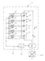
도면에서, 1은 예를 들어 건물의 공급망에 에너지를 공급하기 위해 사용되는, 그리고, 예를 들어, 양방향 AC/DC 컨버터(100)를 통해, 재생 가능 에너지를 생성하기 위한 시스템(태양 광 설비, 풍력 터빈, 바이오가스 플랜트, 등)에 의해 충전 및 방전될 수 있는, 2로 표시된, 에너지 저장 장치를 충전 및 방전하기 위한 기기를 나타낸다. In the figure, 1 indicates a system (solar installation, represents a device for charging and discharging energy storage devices, indicated by 2, which can be charged and discharged by wind turbines, biogas plants, etc.).
도시된 구현의 예에서, 에너지 저장 장치(2)는 5개의 직렬 연결된 충전식 배터리 셀(3-7)을 갖는 셀 블록(20)을 포함하고, 제어 가능한 주 충전/방전 장치(8)에 의해 충전 및 방전될 수 있다.In the example of implementation shown, the energy storage device 2 comprises a
또한, 각각의 배터리 셀(3-7)은 그에 할당된 제어 가능한 보조 충전/방전 장치(9-31)를 통해 셀 블록(20)에 연결된다. 보조 충전/방전 장치(9-13)는 바람직하게는 제어 가능한 양방향 DC/DC 컨버터이다.In addition, each battery cell 3-7 is connected to the
보조 충전/방전 장치(9-31) 및 주 충전/방전 장치(8) 모두에게 대응하는 데이터 라인(15)을 통해 연결된 모니터링 및 제어 장치(14)는 개별 배터리 셀(3-7)의 충전 또는 방전 상태를 점검하기 위해 제공된다. A monitoring and
본 발명에 따른 기기(1)의 에너지 저장 장치(2)의 충전 과정은 아래에서 보다 상세하게 설명된다:The charging process of the energy storage device 2 of the device 1 according to the invention is described in more detail below:
먼저, 개별 배터리 셀(3-7)의 커패시턴스(CN)가 측정되어, 모니터링 및 제어 장치(14)의 메모리에 저장된다(예를 들어, 배터리 셀(3, 5, 6)의 커패시턴스(C3, C5 및 C6)는 약 2 Ah, 배터리 셀(4)의 커패시턴스(C4)는 약 2.5 Ah이고 배터리 셀(7)의 커패시턴스(C7)는 약 3 Ah이다).First, the capacitance C N of the individual battery cells 3-7 is measured and stored in the memory of the monitoring and control device 14 (e.g., the capacitance C N of the
개별 배터리 셀(3-7)이 나중에, 예를 들어 1C의 충전 전류에서, 충전될 경우(C-팩터가 커패시턴스 CN에 대한 최대 충전 전류 IN;max의 몫을 형성함), 모니터링 및 제어 장치(14)는 그 후, 개별 배터리 셀들(3-7)에 대한 최대 충전 전류들 IN;max를 계산하고(상기 언급된 커패시턴스들에 대해, 배터리 셀(3, 5, 6)의 경우 IN;max = C x CN이어서, 각각 2A이고, 배터리 셀(4, 7)의 경우 2.5A 및 3A 임), 이 값을 대응하는 메모리에 저장한다. When the individual battery cells 3-7 are later charged, for example at a charging current of 1 C (the C-factor forms the quotient of the maximum charging current I N;max to the capacitance C N ), monitoring and
비 표시 제어 장치가, 예를 들어 재생 에너지를 생성하기 위한 플랜트의 에너지가 공급망에 필요한 에너지보다 크다고 결정하자 마자, 잉여 에너지의 적어도 일부가 AC/DC 컨버터(100)를 통해 발명에 따른 기기(1)의 주 충전/방전 장치(8)에 도달한다. 기기(1)는 미리 정의된 강도의 직렬 충전 전류 Io를 생성한다.As soon as the non-indicating control device determines, for example, that the energy of the plant for generating renewable energy is greater than the energy required by the supply chain, at least part of the surplus energy is transferred to the device according to the invention (1) via the AC/DC converter (100). ) reaches the main charge/discharge device 8. The device 1 produces a series charging current Io of a predefined strength.
모든 배터리 셀(3-7)에 할당된 최대 충전 전류 IN;max에서 이제 이 셀들을 동시에 충전하기 위해, 모니터링 및 제어 장치(14)는 직렬 충전 전류 Io에 대응하는 최대 충전 전류 IN;max 를 가진 배터리 셀이 직렬 충전 전류 Io에 의해서만 충전됨을 보장한다. 이에 반해, 직렬 충전 전류 Io보다 큰 최대 충전 전류 IN;max를 가진 배터리 셀(3-7)은 적절한 보조 충전/방전 장치(9-13)를 이용하여 셀 블록(20)으로부터 제거될 수 있는 보조 충전 전류 IN에 의해 그리고 직렬 충전 전류 Io에 의해 동시에 충전되며, 이 경우 IN = IN;max - IO이다. 마지막으로, 직렬 충전 전류 Io보다 낮은 최대 충전 전류 IN;max 를 가진 배터리 셀(3-7)은 제 1 충전 전류 I0에 의해 충전되고, 최대 충전 전류 IN;max를 넘는 전류 IO - IN;max 는 셀 블록(20)에 방전 전류로 동시에 공급된다. At the maximum charge current I N;max assigned to all battery cells 3-7, now in order to simultaneously charge these cells, the monitoring and
예를 들어, 최저 커패시턴스를 갖는 배터리 셀(3, 5 및 6)(상기 언급된 예의 경우, 각각 2 Ah)이 최대 충전 전류(Imax = 2A)로 충전되도록 직렬 충전 전류 Io가 선택되는 경우(따라서 IO는 2A), 다른 배터리 셀(4 및 7)은 각각의 배터리 셀(4, 7) 및 최저 커패시턴스를 갖는 배터리 셀(따라서, 배터리 셀(3, 5, 6))의 커패시턴스 간의 차이로부터 나타나는, 이들 간에 할당된 보조 충전/방전 장치(10, 13)로부터 최대 보조 충전 전류(0.5A 또는 1A)에서, 직렬 충전 전류 Io에 추가하여, 각각 충전되어야 한다. For example, if the series charging current Io is selected such that the
배터리 셀(3-7)에서 충전 종료 전압을 모니터링함으로써, 각각의 배터리 셀의 과충전없이 최대 충전 전류에서 배터리 셀(3-7)을 충전할 수 있는 충전 시간(위 예에서 tmax = 1/C = 60분)을 모니터링 및 제어 장치(14)가 모니터링한다. By monitoring the charge end voltage at the battery cells 3-7, the charging time at which the battery cells 3-7 can be charged at the maximum charge current without overcharging of each battery cell (t max = 1/C in the example above) = 60 minutes) is monitored by the monitoring and
예를 들어, 에너지 원의 가용 전압이 낮기 때문에 계산된 최대 충전 전류 IN;max가 모두 가용 직렬 충전 전류 Io보다 큰 경우, 모든 배터리 셀은 계산된 최대 충전 전류 IN;max와 서로 같은 비율로 유지되는 값을 가진 충전 전류로 동시에 충전된다. 따라서, 전술한 실시예에서 직렬 충전 전류 Io가 단 1A 인 경우, 배터리 셀(3, 5 및 6)은 1A에서 충전되고, 배터리 셀(4)은 1.25A에서 충전되고 배터리 셀(7)은 1.5A에서 충전된다.For example, if the calculated maximum charge current I N;max are all greater than the available series charge current Io because the available voltage of the energy source is low, then all battery cells will discharge in equal proportion to the calculated maximum charge current I N;max. They are simultaneously charged with a charging current having a maintained value. Therefore, when the series charging current Io in the above embodiment is only 1A,
직렬 연결된 배터리 셀(3-7)과 함께 미리 정의된 시간 간격으로(예를 들어 100 개의 충전/방전주기마다) 배터리 셀(3-7)의 커패시턴스를 자동으로 결정하기 위해, 먼저 셀 블록(20)이 충전 종료 전압까지 충전되고, 그 후 각각의 개별 배터리 셀(3-7)이 충전 종료 전압에 도달할 때까지 보조 충전/방전 장치(9-13)의 도움으로 더 충전된다. 은 그것의 끝까지 충전된다 충전 전압에 이어 각각의 개별 배터리 셀(3-7)은 충전 종료 전압에 도달할 때까지 그에 할당된 보조 충전/방전 장치(9313)의 도움으로 추가로 충전된다.In order to automatically determine the capacitance of the battery cells 3-7 at predefined time intervals (eg every 100 charge/discharge cycles) with the battery cells 3-7 connected in series, first the cell block 20 ) is charged up to the charge end voltage, after which each individual battery cell 3-7 is further charged with the aid of the auxiliary charge/discharge device 9-13 until the charge end voltage is reached. is charged to its end. Following the charging voltage, each individual battery cell 3-7 is further charged with the help of the auxiliary charge/discharge unit 9313 assigned to it until the charge end voltage is reached.
모든 배터리 셀(3-7)이 충전되면, 기기(1)에 의해 배터리 셀(3-7)의 정해진 방전이 일어난다. 먼저, 전체 셀 블록(20)은 주 충전/방전 장치(8)에 의해 설정된 직렬 방전 전류 Io'에서 80%의 방전 깊이(DoD)로 방전된다. 그 후, 각각의 개별 배터리 셀(3-7)이 할당된 보조 충전/방전 장치(9-13)를 통해 각각의 방전 종료 전압까지 방전된다. When all the battery cells 3-7 are charged, a defined discharge of the battery cells 3-7 by the device 1 takes place. First, the
대응하는 배터리 셀의 커패시턴스 CN이 그 후, 모든 배터리 셀(3-7)의 방전 시작과 각각의 배터리 셀의 방전 종료 전압 도달 사이에서 직렬 방전 전류 Io'의 측정된 코스로부터 결정될 수 있다. The capacitance C N of the corresponding battery cell can then be determined from the measured course of the series discharge current Io' between the start of discharge of all battery cells 3-7 and the arrival of the end-of-discharge voltage of each battery cell.
그러나, 각각의 충전 프로세스의 시간 경과는 또한 배터리 셀의 커패시턴스를 측정하기 위해 사용될 수 있고, 또는, 배터리의 충전 및 방전 동안 결정된 커패시턴스 값 사이의 평균값이 사용될 수 있다.However, the time course of each charging process can also be used to measure the capacitance of a battery cell, or an average value between capacitance values determined during charging and discharging of the battery can be used.
물론, 본 발명은 본 실시예로 제한되지 않는다.Of course, the present invention is not limited to this embodiment.
예를 들어, 배터리 셀(3-7)의 커패시턴스는, 주 충전/방전 장치(8)에 의해 생성된 직렬 충전 전류 Io에 의해 그들의 충전 종료 전압에 도달할 때까지 모든 배터리 셀(3-7)을 먼저 충전함으로써, 또한 결정될 수 있다. 최대 커패시턴스를 갖는 배터리 셀(들)(상기 예에서 배터리 셀 7)보다 충전 종료 전압이 낮은 배터리 셀의 과충전을 방지하기 위해, 잉여 전류가 할당된 보조 충전/방전 장치(9-13)를 통해 셀 블록(20)에 공급된다.For example, the capacitance of the battery cells 3-7 is reduced by the series charge current Io generated by the main charge/discharge device 8 until their end-of-charge voltage is reached. By first charging , it can also be determined. In order to prevent overcharging of a battery cell having a lower end-of-charge voltage than the battery cell(s) having the maximum capacitance (battery cell 7 in the example above), a surplus current is assigned to the cell through an auxiliary charge/discharge device 9-13. supplied to block 20.
모든 배터리 셀(3-7)이 충전되면, 기기(1)에 의해 배터리 셀(3-7)의 정해진 방전이 일어난다. 이를 위해, 배터리 셀(3-7)은 최고 커패시턴스를 가진 배터리 셀의 방전 종료 전압에 도달할 때까지 주 충전/방전 장치(8)에 의해 설정된 직렬 방전 전류 Io'로 방전된다. 최고 커패시턴스를 가진 배터리보다 먼저 방전 종료 전압에 도달한 배터리 셀의 과소충전을 피하기 위해, 방전 종료 전압에 도달한 후, 이 배터리 셀들은 할당된 보조 충전/방전 장치에 의해 셀 블록(20)으로부터 보조 충전 전류를 공급받는다. When all the battery cells 3-7 are charged, a defined discharge of the battery cells 3-7 by the device 1 takes place. To this end, the battery cells 3-7 are discharged with the set series discharge current Io' by the main charge/discharge device 8 until the end-of-discharge voltage of the battery cell with the highest capacitance is reached. To avoid undercharging battery cells that reach the end-of-discharge voltage before the battery with the highest capacitance, after reaching the end-of-discharge voltage, these battery cells are sub-charged from the
이어서, 모든 배터리 셀(3-7)의 방전 시작과 각각의 배터리 셀의 방전 종료 전압 도달 간에 직렬 방전 전류 Io'의 측정 코스로부터 대응하는 배터리 셀의 커패시턴스 CN이 결정될 수 있다. Subsequently, the capacitance C N of the corresponding battery cell can be determined from the measurement course of the series discharge current Io' between the discharge start of all the battery cells 3-7 and the arrival of the discharge end voltage of each battery cell.
더욱이, 모든 배터리 셀의 커패시턴스가 하나의 충전/방전 사이클에서 결정되어야하는 것이 아니다. 대신, 다수의 충전/방전 사이클에서 배터리 셀의 커패시턴스를 차례로 결정하는 것이 또한 유리할 수 있다. Moreover, not all battery cell capacitances have to be determined in one charge/discharge cycle. Instead, it may also be advantageous to sequentially determine the capacitance of a battery cell over multiple charge/discharge cycles.
또한, 직렬 충전 또는 방전 전류가 반드시, 최저 커패시턴스를 갖는 배터리 셀의 최대 충전 또는 방전 전류에 대응하도록 선택될 필요는 없다. 대신, 예를 들어, 평균 커패시턴스를 갖는 배터리 셀 또는 최고 커패시턴스를 갖는 배터리 셀, 등의 최대 충전 또는 방전 전류에 대응하도록 선택될 수 있다. Also, the series charge or discharge current is not necessarily selected to correspond to the maximum charge or discharge current of the battery cell with the lowest capacitance. Instead, it may be selected to correspond to the maximum charge or discharge current of, for example, the battery cell with the average capacitance or the battery cell with the highest capacitance.
마지막으로, 에너지 저장 장치는 직렬 배터리 저장소를 포함하는 다수의 셀 블록으로 또한 구성될 수 있다. Finally, the energy storage device may also consist of multiple cell blocks including series battery storage.
Claims (9)
a) 미리 정의된 시간 간격으로, 개별 배터리 셀(3-7)의 커패시턴스(CN)가 측정되어 모니터링 및 제어 장치(14)의 메모리에 저장되고;
b) 미리 정의된 C-팩터(커패시턴스 CN에 대한 최대 충전 전류 IN;max의 몫)에 기초하여, 개별 커패시턴스(CN)의 특성인 최대 충전 전류 IN;max가 모니터링 및 제어 장치(14)에 의해 결정되며,
c) 이어서, 미리 정의된 시간 t <= 1/C-팩터 동안, 배터리 셀(3-7)은 이들 배터리 셀(3-7)에 할당된 최대 충전 전류 IN;max에서 동시에 충전되고,
- 직렬 충전 전류 Io에 해당하는 최대 충전 전류 IN;max를 가진 배터리 셀(3-7)은 직렬 충전 전류 Io에 의해서만 충전되며,
- 직렬 충전 전류 Io보다 큰 최대 충전 전류 IN;max 를 가진 배터리 셀(3-7)은 보조 충전/방전 장치(9-13)를 통해 셀 블록(20)으로부터 제거될 수 있는 보조 충전 전류 IN 및 직렬 충전 전류 Io에 의해 동시에 충전되고, 이 경우 IN = IN;max - IO 이며,
- 직렬 충전 전류 Io보다 낮은 최대 충전 전류 IN;max를 갖는 배터리 셀(3-7)은 직렬 충전 전류 IO에 의해 충전되고, 최대 충전 전류 IN;max을 초과하는 전류 IO - IN;max는 대응하는 보조 충전/방전 장치를 통해 보조 방전 전류로서 셀 블록(20)에 동시에 공급되며,
또는 계산된 최대 충전 전류 IN;max가 모두 가용한 직렬 충전 전류 Io보다 큰 경우, 계산된 최대 충전 전류 IN;max와 서로 동일한 비율의 값을 갖는 충전 전류로 배터리 셀을 동시에 충전하는, 방법.A method of charging an energy storage device (2) with at least one cell block (20) composed of a plurality of series-connected battery cells (3-7) by a series charging current Io flowing through all the battery cells (3-7). , at least some of the battery cells 3-7 have different capacitances C N ,
a) at predefined time intervals, the capacitance C N of individual battery cells 3-7 is measured and stored in the memory of the monitoring and control device 14;
b) Based on a predefined C-factor (the quotient of the maximum charging current I N;max to the capacitance C N ), the characteristic of the individual capacitance (C N ), the maximum charging current I N;max is monitored and controlled by a device ( 14) is determined by
c) Then, during a predefined time t <= 1/C-factor, the battery cells 3-7 are simultaneously charged at the maximum charging current I N;max assigned to these battery cells 3-7,
- battery cells (3-7) with a maximum charge current I N;max corresponding to the series charge current Io are charged only by the series charge current Io;
- battery cells 3-7 with a maximum charge current I N;max greater than the series charge current Io, an auxiliary charge current I that can be removed from the cell block 20 via an auxiliary charge/discharge device 9-13; Simultaneously charged by N and the series charge current Io, in which case I N = I N;max - I O ;
- the battery cell 3-7 having a maximum charge current I N;max lower than the series charge current Io is charged by the series charge current IO, and a current I O - I N exceeding the maximum charge current I N;max ; max is simultaneously supplied to the cell block 20 as an auxiliary discharge current through a corresponding auxiliary charge/discharge device,
Alternatively, if the calculated maximum charging current I N;max are both greater than the available series charging current Io, the battery cell is simultaneously charged with a charging current having a value in the same ratio as the calculated maximum charging current I N;max . .
a) 미리 정의된 시간 간격으로, 개별 배터리 셀(3-7)의 커패시턴스(CN)가 측정되어 모니터링 및 제어 장치(14)의 메모리에 저장되고;
b) 미리 정의된 C-팩터(커패시턴스 CN에 대한 최대 충전 전류 IN;max의 몫)에 기초하여, 개별 커패시턴스(CN)의 특성인 최대 방전 전류 IN;max가 모니터링 및 제어 장치(14)에 의해 결정되며,
c) 이어서, 미리 정의된 시간 t <= 1/C-팩터 동안, 배터리 셀(3-7)은 이들 배터리 셀(3-7)에 할당된 최대 방전 전류 IN;max에서 방전되고, 이와 동시에,
- 직렬 방전 전류 Io'에 해당하는 최대 방전 전류 IN;max를 가진 배터리 셀(3-7)은 직렬 방전 전류 Io'에 의해서만 방전되며,
- 직렬 방전 전류 Io'보다 큰 최대 방전 전류 IN;max 를 가진 배터리 셀(3-7)은 보조 충전/방전 장치(9-13)를 통해 셀 블록(20)으로부터 제거될 수 있는 보조 방전 전류 IN'및 직렬 방전 전류 Io'에 의해 동시에 방전되고, 이 경우 IN' = IN;max - IO'이며,
- 직렬 방전 전류 Io'보다 낮은 최대 방전 전류 IN;max를 갖는 배터리 셀(3-7)은 직렬 방전 전류 Io'에 의해 방전되고, 최대 방전 전류를 초과하는 전류 IO' - IN;max는 대응하는 보조 충전/방전 장치(9-13)를 통해 보조 충전 전류로서 셀 블록(20)에 동시에 공급되는, 방법.The energy storage device 2 is discharged by at least one cell block 20 composed of a plurality of series-connected battery cells 3-7 by a series discharge current Io' flowing through all the battery cells 3-7. As a method, at least some of the battery cells 3-7 have different capacitances (C N ),
a) at predefined time intervals, the capacitance C N of individual battery cells 3-7 is measured and stored in the memory of the monitoring and control device 14;
b) Based on a predefined C-factor (the quotient of the maximum charge current I N;max to the capacitance C N ), the maximum discharge current I N;max , which is a characteristic of the individual capacitance (C N ), is monitored and controlled by a device ( 14) is determined by
c) Then, during a predefined time t <= 1/C-factor, the battery cells 3-7 are discharged at the maximum discharge current I N;max assigned to these battery cells 3-7, and at the same time ,
- the battery cells 3-7 having the maximum discharge current I N;max corresponding to the series discharge current Io' are discharged only by the series discharge current Io';
- auxiliary discharge current that can be removed from the cell block 20 through the auxiliary charge/discharge device 9-13 for battery cells 3-7 having a maximum discharge current I N;max greater than the series discharge current Io' Simultaneously discharged by I N 'and series discharge current Io', in this case I N ' = I N;max - I O ',
- The battery cell 3-7 having a maximum discharge current I N;max lower than the series discharge current Io' is discharged by the series discharge current Io', and a current exceeding the maximum discharge current I O ' - I N;max is simultaneously supplied to the cell block 20 as an auxiliary charge current through a corresponding auxiliary charge/discharge device 9-13.
먼저, 전체 셀 블록(20)이 충전 종료 전압 도달시까지 직렬 충전 전류 Io에 의해 충전된 다음, 셀 블록(20)의 각각의 개별 배터리 셀(3-7)이 충전 종료 전압 도달시까지 할당된 보조 충전/방전 장치(9-13)의 도움으로 추가로 충전되고,
그 후, 셀 블록(20)은 80%의 방전 깊이까지 직렬 방전 전류(Io')로 방전되고, 각각의 개별 배터리 셀(3-7)은 각각 할당된 보조 충전/방전 장치(9-13)를 통해 각각의 방전 종료 전압까지 방전되며,
마지막으로, 시간에 따라 적분된 셀 블록 및 개별 배터리 셀의 방전 전류로부터 각각의 커패시턴스가 결정되는, 방법.According to claim 6,
First, the entire cell block 20 is charged by the series charging current Io until the charging end voltage is reached, and then each individual battery cell 3-7 of the cell block 20 is assigned until the charging end voltage is reached. additionally charged with the aid of an auxiliary charge/discharge unit (9-13);
Then, the cell block 20 is discharged with a series discharge current (Io') to a discharge depth of 80%, and each individual battery cell 3-7 is connected to an auxiliary charge/discharge device 9-13 assigned to each. It is discharged to each discharge end voltage through
Finally, the capacitance of each is determined from the discharge currents of the cell block and individual battery cells integrated over time.
먼저, 모든 배터리 셀(3-7)이 충전 종료 전압 도달시까지 직렬 충전 전류 Io에 의해 충전되고, 최대 커패시턴스를 갖는 배터리 셀(3-7)보다 낮은 충전 종료 전압을 가진 배터리 셀(3-7)의 과충전은 각각 할당된 셀 블록(20)의 보조 충전/방전 장치(9-13)를 통해 공급되는 잉여 전류에 의해 방지되며,
이어서, 배터리 셀(3-7)은 최대 커패시턴스를 갖는 배터리 셀(3-7)의 방전 종료 전압 도달시까지 미리 정의된 직렬 방전 전류(Io')로 방전되고, 최대 커패시턴스를 가진 배터리(3-7)에 앞서 방전 종료 전압에 도달한 배터리 셀(3-7)의 과소충전을 피하기 위해, 할당된 보조 충전/방전 장치(9-13)를 통해 셀 블록(20)으로부터 배터리 셀(3-7)로 보조 충전 전류가 공급되며,
그 후 각 배터리 셀(3-7)의 커패시턴스는 배터리 셀(3-7)의 충전된 상태와 각각의 배터리 셀의 방전 종료 전압 도달 간의 방전 전류(Io')의 측정된 시간 코스로부터 결정되는, 방법.According to claim 6,
First, all of the battery cells 3-7 are charged by the series charging current Io until the charging end voltage is reached, and the battery cells 3-7 having a lower end-of-charge voltage than the battery cells 3-7 having the maximum capacitance. ) is prevented from being overcharged by the surplus current supplied through the auxiliary charge/discharge devices 9-13 of each assigned cell block 20,
Subsequently, the battery cell 3-7 is discharged with a predefined series discharge current (Io') until the discharge end voltage of the battery cell 3-7 with the maximum capacitance is reached, and the battery with the maximum capacitance (3-7) In order to avoid undercharging of the battery cells 3-7 that have reached the discharge end voltage prior to 7), the battery cells 3-7 are discharged from the cell block 20 through the assigned auxiliary charge/discharge device 9-13. ), the auxiliary charging current is supplied,
The capacitance of each battery cell 3-7 is then determined from the measured time course of the discharge current Io' between the charged state of the battery cell 3-7 and the arrival of the end-of-discharge voltage of each battery cell. method.
Applications Claiming Priority (3)
| Application Number | Priority Date | Filing Date | Title |
|---|---|---|---|
| DE102017009850.6A DE102017009850B4 (en) | 2017-10-23 | 2017-10-23 | Method for charging and discharging an energy store |
| DE102017009850.6 | 2017-10-23 | ||
| PCT/EP2018/070791 WO2019081084A1 (en) | 2017-10-23 | 2018-07-31 | Method for charging or discharging an energy store |
Publications (2)
| Publication Number | Publication Date |
|---|---|
| KR20200078506A KR20200078506A (en) | 2020-07-01 |
| KR102549135B1 true KR102549135B1 (en) | 2023-06-28 |
Family
ID=63174198
Family Applications (1)
| Application Number | Title | Priority Date | Filing Date |
|---|---|---|---|
| KR1020207011853A KR102549135B1 (en) | 2017-10-23 | 2018-07-31 | How to charge or discharge an energy storage device |
Country Status (11)
| Country | Link |
|---|---|
| US (1) | US11205910B2 (en) |
| EP (1) | EP3701584B1 (en) |
| JP (1) | JP7102516B2 (en) |
| KR (1) | KR102549135B1 (en) |
| CN (1) | CN111263998B (en) |
| AU (1) | AU2018355632B2 (en) |
| CA (1) | CA3079425C (en) |
| DE (1) | DE102017009850B4 (en) |
| ES (1) | ES2924356T3 (en) |
| RU (1) | RU2736777C1 (en) |
| WO (1) | WO2019081084A1 (en) |
Families Citing this family (11)
| Publication number | Priority date | Publication date | Assignee | Title |
|---|---|---|---|---|
| DE102011078461A1 (en) | 2011-06-30 | 2013-01-03 | Röchling Automotive AG & Co. KG | Damage-proof damper arrangement |
| DE102019126692A1 (en) * | 2019-10-02 | 2021-04-08 | Benning CMS Technology GmbH | Method for charging and discharging a rechargeable energy storage and energy storage system |
| US11056728B2 (en) * | 2019-10-31 | 2021-07-06 | Sion Power Corporation | System and method for operating a rechargeable electrochemical cell or battery |
| DE102019129415B3 (en) | 2019-10-31 | 2021-01-14 | Benning CMS Technology GmbH | Method for charging and / or discharging a rechargeable energy store |
| US11424492B2 (en) | 2019-10-31 | 2022-08-23 | Sion Power Corporation | System and method for operating a rechargeable electrochemical cell or battery |
| DE102019217303A1 (en) * | 2019-11-08 | 2021-05-12 | Robert Bosch Gmbh | Method for operating a battery module, battery module for a motor vehicle and motor vehicle |
| DE102020204744A1 (en) | 2020-04-15 | 2021-10-21 | Robert Bosch Gesellschaft mit beschränkter Haftung | Method for operating a battery pack and battery pack |
| WO2021217530A1 (en) * | 2020-04-29 | 2021-11-04 | 华为技术有限公司 | Energy storage system |
| DE102020003062A1 (en) | 2020-05-23 | 2021-11-25 | Marquardt Gmbh | Method for operating a battery system |
| DE102022109869A1 (en) | 2022-04-25 | 2023-10-26 | Benning CMS Technology GmbH | Method for charging a rechargeable energy storage device |
| DE102022109884A1 (en) | 2022-04-25 | 2023-10-26 | Benning CMS Technology GmbH | Method for determining the capacities of the battery cells of a rechargeable energy storage device |
Citations (3)
| Publication number | Priority date | Publication date | Assignee | Title |
|---|---|---|---|---|
| WO2007033791A2 (en) | 2005-09-21 | 2007-03-29 | Zentrum für Sonnenenergie- und Wasserstoff-Forschung Baden-Württemberg | Charging method for extending a battery service life and device for carrying out said method |
| JP2010220380A (en) | 2009-03-17 | 2010-09-30 | Nissan Motor Co Ltd | Device for adjusting capacity of battery pack |
| US20130271068A1 (en) | 2010-12-16 | 2013-10-17 | Honda Motor Co., Ltd. | Battery control apparatus and battery control method |
Family Cites Families (23)
| Publication number | Priority date | Publication date | Assignee | Title |
|---|---|---|---|---|
| JP3071488B2 (en) * | 1991-04-18 | 2000-07-31 | 新電元工業株式会社 | Battery charger |
| NL1000568C2 (en) * | 1994-12-08 | 1996-09-12 | Tno | Method and device for rapid charging of accumulators or batteries. |
| JPH10191574A (en) * | 1996-12-26 | 1998-07-21 | Japan Tobacco Inc | Charging equipment |
| JP3796918B2 (en) * | 1997-09-30 | 2006-07-12 | 株式会社デンソー | Battery device |
| JP2000228830A (en) * | 1999-02-05 | 2000-08-15 | Toyama Prefecture | Charging method and apparatus for secondary battery |
| JP3869585B2 (en) * | 1999-07-30 | 2007-01-17 | 三洋電機株式会社 | Discharge method of multiple secondary batteries and assembled battery |
| JP3676154B2 (en) * | 1999-11-29 | 2005-07-27 | 三洋電機株式会社 | Charge / discharge control method for battery pack |
| DE102004031216A1 (en) * | 2004-06-28 | 2006-01-19 | Siemens Ag | Apparatus and method for charge equalization in series connected energy storage |
| WO2008137764A1 (en) * | 2007-05-03 | 2008-11-13 | Sendyne Corporation | Fine-controlled battery-charging system |
| JP2009081981A (en) * | 2007-09-27 | 2009-04-16 | Sanyo Electric Co Ltd | Charge state optimizing apparatus and battery pack system provided therewith |
| KR101160755B1 (en) | 2008-01-14 | 2012-06-28 | 도요타지도샤가부시키가이샤 | Lithium ion secondary cell charge method and hybrid vehicle |
| JP4811446B2 (en) * | 2008-10-21 | 2011-11-09 | トヨタ自動車株式会社 | Power supply system, vehicle equipped with the same, and control method of power supply system |
| CN101409455B (en) * | 2008-11-19 | 2011-10-26 | 华为终端有限公司 | Voltage balance apparatus and method for battery system |
| JP5564864B2 (en) * | 2008-12-19 | 2014-08-06 | 日産自動車株式会社 | Secondary battery system |
| JP2011177011A (en) * | 2010-01-29 | 2011-09-08 | Sanyo Electric Co Ltd | Device for adjusting state of charge, battery system with the same, electric vehicle, moving body, power storage device, power supply device, and program for processing state of charge adjustment |
| FR2959885B1 (en) * | 2010-05-05 | 2014-12-05 | Commissariat Energie Atomique | POWER BATTERY BALANCING SYSTEM, LOAD BALANCING METHOD, AND CORRESPONDING CHARGE AND FEED BALANCING COMBINATION METHOD |
| DE102010017439A1 (en) | 2010-06-17 | 2011-12-22 | Bmz Batterien-Montage-Zentrum Gmbh | Energy balancing circuit configuration for, e.g. traction accumulator of vehicle, has chargers to perform charging process of cells of energy storage unit using balancing currents, with smaller load |
| WO2012139604A1 (en) * | 2011-04-12 | 2012-10-18 | E-Moove Gmbh | Method for operating an energy storage assembly |
| KR101473324B1 (en) * | 2011-11-04 | 2014-12-16 | 삼성에스디아이 주식회사 | Apparatus for managing battery, method for balancing battery cells, and energy storage system |
| DE102012020544A1 (en) | 2012-10-19 | 2014-04-24 | Wolfram Walter | Device for charging two serially connected battery cells of energy storage i.e. battery, has charging devices connected with battery cells of energy storage and connected with power supply independent of state of charge of cells |
| DE102013005104A1 (en) * | 2013-03-23 | 2014-10-09 | Wolfram Walter | Device and method for charging and discharging an energy storage device |
| DE102015007405A1 (en) * | 2015-06-08 | 2016-12-08 | ASD Automatic Storage Device GmbH | Energy storage system |
| WO2017090155A1 (en) * | 2015-11-26 | 2017-06-01 | 株式会社東芝 | Power control device and power control system |
-
2017
- 2017-10-23 DE DE102017009850.6A patent/DE102017009850B4/en active Active
-
2018
- 2018-07-31 KR KR1020207011853A patent/KR102549135B1/en active IP Right Grant
- 2018-07-31 AU AU2018355632A patent/AU2018355632B2/en active Active
- 2018-07-31 ES ES18753334T patent/ES2924356T3/en active Active
- 2018-07-31 CA CA3079425A patent/CA3079425C/en active Active
- 2018-07-31 US US16/755,920 patent/US11205910B2/en active Active
- 2018-07-31 WO PCT/EP2018/070791 patent/WO2019081084A1/en unknown
- 2018-07-31 EP EP18753334.4A patent/EP3701584B1/en active Active
- 2018-07-31 CN CN201880069071.3A patent/CN111263998B/en active Active
- 2018-07-31 JP JP2020521316A patent/JP7102516B2/en active Active
- 2018-07-31 RU RU2020116449A patent/RU2736777C1/en active
Patent Citations (3)
| Publication number | Priority date | Publication date | Assignee | Title |
|---|---|---|---|---|
| WO2007033791A2 (en) | 2005-09-21 | 2007-03-29 | Zentrum für Sonnenenergie- und Wasserstoff-Forschung Baden-Württemberg | Charging method for extending a battery service life and device for carrying out said method |
| JP2010220380A (en) | 2009-03-17 | 2010-09-30 | Nissan Motor Co Ltd | Device for adjusting capacity of battery pack |
| US20130271068A1 (en) | 2010-12-16 | 2013-10-17 | Honda Motor Co., Ltd. | Battery control apparatus and battery control method |
Also Published As
| Publication number | Publication date |
|---|---|
| CN111263998B (en) | 2023-06-20 |
| CA3079425A1 (en) | 2019-05-02 |
| KR20200078506A (en) | 2020-07-01 |
| AU2018355632A1 (en) | 2020-05-07 |
| ES2924356T3 (en) | 2022-10-06 |
| JP7102516B2 (en) | 2022-07-19 |
| CA3079425C (en) | 2022-07-26 |
| DE102017009850A1 (en) | 2019-04-25 |
| AU2018355632B2 (en) | 2021-08-12 |
| EP3701584B1 (en) | 2022-05-25 |
| RU2736777C1 (en) | 2020-11-20 |
| WO2019081084A1 (en) | 2019-05-02 |
| JP2021500840A (en) | 2021-01-07 |
| CN111263998A (en) | 2020-06-09 |
| US11205910B2 (en) | 2021-12-21 |
| EP3701584A1 (en) | 2020-09-02 |
| US20200343736A1 (en) | 2020-10-29 |
| DE102017009850B4 (en) | 2020-04-02 |
Similar Documents
| Publication | Publication Date | Title |
|---|---|---|
| KR102549135B1 (en) | How to charge or discharge an energy storage device | |
| JP5784108B2 (en) | Charge control device | |
| US20130311119A1 (en) | Method of detecting battery full-charge capacity | |
| JP2010098866A (en) | Imbalance determination circuit, imbalance reduction circuit, battery power supply, and imbalance evaluation method | |
| CN103314501A (en) | Battery control apparatus and battery control method | |
| US9184600B2 (en) | Method for balancing the voltages of electrochemical cells connected in several parallel branches | |
| JPWO2012043134A1 (en) | Storage battery charge / discharge control device and storage battery charge / discharge control method | |
| CN102197563A (en) | Failure diagnosis circuit, power supply device, and failure diagnosis method | |
| KR102045047B1 (en) | Maximum capacity charging apparatus considering SOH unbalance of battery module and control method thereof | |
| WO2010010662A1 (en) | Imbalance determination circuit, power supply device, and imbalance determination method | |
| US20220384863A1 (en) | Method for charging and/or discharging a rechargeable energy store | |
| CN105934682A (en) | Method of estimating the residual capacities of a plurality of batteries | |
| JP4749290B2 (en) | Power supply device and voltage management IC used therefor | |
| JP2016167928A (en) | Charge and discharge system | |
| CN103988385A (en) | Energy storage system balancing device | |
| JPWO2019081084A5 (en) | ||
| KR101925113B1 (en) | Battery Pack Charger for Improving Charge of Battery Pack Comprising Multiple Battery Units | |
| CN111799853A (en) | Cell voltage balancing method and equipment for battery cells of multi-cell energy storage device | |
| KR101736419B1 (en) | Charging method for battery capable of prevent overcharge | |
| KR102020044B1 (en) | Battery charging system, and method for controlling maximum capacity charging in battery module using the same | |
| RU2638825C2 (en) | Method for operation of lithium-ion accumulator battery as part of autonomous system of power supply of artifical earth satellite | |
| KR20130129508A (en) | Device for voltage balancing of battery pack and balancing process using the same | |
| CN116264410A (en) | Charging method, charger and charging system for lithium battery | |
| AU2016238069A1 (en) | Storage battery management device, control device, storage battery module, and storage battery management method | |
| EP3134951A1 (en) | Optimized energy transfer algorithm for energy storage arrangement |
Legal Events
| Date | Code | Title | Description |
|---|---|---|---|
| A201 | Request for examination | ||
| E902 | Notification of reason for refusal | ||
| E701 | Decision to grant or registration of patent right | ||
| GRNT | Written decision to grant |