KR102503155B1 - Multi-depth flat display system with reduced switching between depth planes - Google Patents
Multi-depth flat display system with reduced switching between depth planes Download PDFInfo
- Publication number
- KR102503155B1 KR102503155B1 KR1020187026210A KR20187026210A KR102503155B1 KR 102503155 B1 KR102503155 B1 KR 102503155B1 KR 1020187026210 A KR1020187026210 A KR 1020187026210A KR 20187026210 A KR20187026210 A KR 20187026210A KR 102503155 B1 KR102503155 B1 KR 102503155B1
- Authority
- KR
- South Korea
- Prior art keywords
- virtual object
- cues
- user
- accommodation
- depth
- Prior art date
Links
- 230000002829 reductive effect Effects 0.000 title description 4
- 238000000034 method Methods 0.000 claims abstract description 53
- 230000004308 accommodation Effects 0.000 claims description 78
- 238000006073 displacement reaction Methods 0.000 claims description 12
- 230000009471 action Effects 0.000 claims description 10
- 238000003860 storage Methods 0.000 claims description 8
- 230000004424 eye movement Effects 0.000 claims description 4
- 238000012544 monitoring process Methods 0.000 claims description 2
- 230000000717 retained effect Effects 0.000 claims description 2
- 230000003190 augmentative effect Effects 0.000 abstract description 18
- 230000009467 reduction Effects 0.000 abstract description 2
- 230000003287 optical effect Effects 0.000 description 83
- 238000010168 coupling process Methods 0.000 description 68
- 238000005859 coupling reaction Methods 0.000 description 68
- 238000012545 processing Methods 0.000 description 39
- 230000008569 process Effects 0.000 description 20
- 238000009826 distribution Methods 0.000 description 18
- 230000008859 change Effects 0.000 description 17
- 238000002347 injection Methods 0.000 description 14
- 239000007924 injection Substances 0.000 description 14
- 239000000463 material Substances 0.000 description 12
- 210000001747 pupil Anatomy 0.000 description 11
- 239000003086 colorant Substances 0.000 description 10
- 230000000007 visual effect Effects 0.000 description 9
- 238000010586 diagram Methods 0.000 description 8
- 239000000835 fiber Substances 0.000 description 8
- 230000004044 response Effects 0.000 description 8
- 238000003384 imaging method Methods 0.000 description 6
- 230000033001 locomotion Effects 0.000 description 6
- 230000004048 modification Effects 0.000 description 6
- 238000012986 modification Methods 0.000 description 6
- 238000004891 communication Methods 0.000 description 5
- 230000006870 function Effects 0.000 description 5
- 230000008447 perception Effects 0.000 description 5
- 238000012800 visualization Methods 0.000 description 5
- 241000153282 Theope Species 0.000 description 4
- 238000005253 cladding Methods 0.000 description 4
- 238000005516 engineering process Methods 0.000 description 4
- 238000000605 extraction Methods 0.000 description 4
- 238000000926 separation method Methods 0.000 description 4
- 239000013598 vector Substances 0.000 description 4
- 230000008901 benefit Effects 0.000 description 3
- 210000004556 brain Anatomy 0.000 description 3
- 230000007423 decrease Effects 0.000 description 3
- 210000000613 ear canal Anatomy 0.000 description 3
- 239000013307 optical fiber Substances 0.000 description 3
- 230000006461 physiological response Effects 0.000 description 3
- 230000001902 propagating effect Effects 0.000 description 3
- 206010019233 Headaches Diseases 0.000 description 2
- 238000013459 approach Methods 0.000 description 2
- 230000005540 biological transmission Effects 0.000 description 2
- 230000004397 blinking Effects 0.000 description 2
- 230000004438 eyesight Effects 0.000 description 2
- 230000014509 gene expression Effects 0.000 description 2
- 231100000869 headache Toxicity 0.000 description 2
- 230000000670 limiting effect Effects 0.000 description 2
- 239000004973 liquid crystal related substance Substances 0.000 description 2
- 238000005259 measurement Methods 0.000 description 2
- 230000035790 physiological processes and functions Effects 0.000 description 2
- 239000000047 product Substances 0.000 description 2
- 230000000644 propagated effect Effects 0.000 description 2
- 230000011514 reflex Effects 0.000 description 2
- 210000001525 retina Anatomy 0.000 description 2
- 238000004088 simulation Methods 0.000 description 2
- 230000016776 visual perception Effects 0.000 description 2
- 239000004983 Polymer Dispersed Liquid Crystal Substances 0.000 description 1
- XUIMIQQOPSSXEZ-UHFFFAOYSA-N Silicon Chemical compound [Si] XUIMIQQOPSSXEZ-UHFFFAOYSA-N 0.000 description 1
- 230000002350 accommodative effect Effects 0.000 description 1
- 230000002730 additional effect Effects 0.000 description 1
- 230000004075 alteration Effects 0.000 description 1
- 208000003464 asthenopia Diseases 0.000 description 1
- 230000003416 augmentation Effects 0.000 description 1
- 238000004422 calculation algorithm Methods 0.000 description 1
- 230000002860 competitive effect Effects 0.000 description 1
- 210000004087 cornea Anatomy 0.000 description 1
- 238000013500 data storage Methods 0.000 description 1
- 230000003247 decreasing effect Effects 0.000 description 1
- 238000011161 development Methods 0.000 description 1
- 230000026058 directional locomotion Effects 0.000 description 1
- 230000000694 effects Effects 0.000 description 1
- 239000000284 extract Substances 0.000 description 1
- 206010016256 fatigue Diseases 0.000 description 1
- 210000003128 head Anatomy 0.000 description 1
- 238000002513 implantation Methods 0.000 description 1
- 238000003331 infrared imaging Methods 0.000 description 1
- 230000003993 interaction Effects 0.000 description 1
- 239000011344 liquid material Substances 0.000 description 1
- 238000004519 manufacturing process Methods 0.000 description 1
- 230000006855 networking Effects 0.000 description 1
- 230000002093 peripheral effect Effects 0.000 description 1
- 239000012466 permeate Substances 0.000 description 1
- 230000004478 pupil constriction Effects 0.000 description 1
- 230000010344 pupil dilation Effects 0.000 description 1
- 238000009877 rendering Methods 0.000 description 1
- 230000003252 repetitive effect Effects 0.000 description 1
- 230000004434 saccadic eye movement Effects 0.000 description 1
- 238000007493 shaping process Methods 0.000 description 1
- 229910052710 silicon Inorganic materials 0.000 description 1
- 239000010703 silicon Substances 0.000 description 1
- 239000007787 solid Substances 0.000 description 1
- 239000011343 solid material Substances 0.000 description 1
- 125000006850 spacer group Chemical group 0.000 description 1
- 230000003068 static effect Effects 0.000 description 1
- 230000000638 stimulation Effects 0.000 description 1
- 239000000758 substrate Substances 0.000 description 1
Images


Classifications
-
- H—ELECTRICITY
- H04—ELECTRIC COMMUNICATION TECHNIQUE
- H04N—PICTORIAL COMMUNICATION, e.g. TELEVISION
- H04N13/00—Stereoscopic video systems; Multi-view video systems; Details thereof
- H04N13/10—Processing, recording or transmission of stereoscopic or multi-view image signals
- H04N13/106—Processing image signals
- H04N13/128—Adjusting depth or disparity
-
- G—PHYSICS
- G06—COMPUTING; CALCULATING OR COUNTING
- G06T—IMAGE DATA PROCESSING OR GENERATION, IN GENERAL
- G06T19/00—Manipulating 3D models or images for computer graphics
- G06T19/006—Mixed reality
-
- A—HUMAN NECESSITIES
- A61—MEDICAL OR VETERINARY SCIENCE; HYGIENE
- A61B—DIAGNOSIS; SURGERY; IDENTIFICATION
- A61B3/00—Apparatus for testing the eyes; Instruments for examining the eyes
- A61B3/10—Objective types, i.e. instruments for examining the eyes independent of the patients' perceptions or reactions
- A61B3/113—Objective types, i.e. instruments for examining the eyes independent of the patients' perceptions or reactions for determining or recording eye movement
-
- G—PHYSICS
- G02—OPTICS
- G02B—OPTICAL ELEMENTS, SYSTEMS OR APPARATUS
- G02B27/00—Optical systems or apparatus not provided for by any of the groups G02B1/00 - G02B26/00, G02B30/00
- G02B27/01—Head-up displays
- G02B27/017—Head mounted
-
- G—PHYSICS
- G02—OPTICS
- G02B—OPTICAL ELEMENTS, SYSTEMS OR APPARATUS
- G02B27/00—Optical systems or apparatus not provided for by any of the groups G02B1/00 - G02B26/00, G02B30/00
- G02B27/01—Head-up displays
- G02B27/017—Head mounted
- G02B27/0172—Head mounted characterised by optical features
-
- G—PHYSICS
- G02—OPTICS
- G02B—OPTICAL ELEMENTS, SYSTEMS OR APPARATUS
- G02B30/00—Optical systems or apparatus for producing three-dimensional [3D] effects, e.g. stereoscopic images
- G02B30/20—Optical systems or apparatus for producing three-dimensional [3D] effects, e.g. stereoscopic images by providing first and second parallax images to an observer's left and right eyes
- G02B30/26—Optical systems or apparatus for producing three-dimensional [3D] effects, e.g. stereoscopic images by providing first and second parallax images to an observer's left and right eyes of the autostereoscopic type
- G02B30/27—Optical systems or apparatus for producing three-dimensional [3D] effects, e.g. stereoscopic images by providing first and second parallax images to an observer's left and right eyes of the autostereoscopic type involving lenticular arrays
-
- G—PHYSICS
- G02—OPTICS
- G02B—OPTICAL ELEMENTS, SYSTEMS OR APPARATUS
- G02B6/00—Light guides; Structural details of arrangements comprising light guides and other optical elements, e.g. couplings
-
- G—PHYSICS
- G02—OPTICS
- G02B—OPTICAL ELEMENTS, SYSTEMS OR APPARATUS
- G02B6/00—Light guides; Structural details of arrangements comprising light guides and other optical elements, e.g. couplings
- G02B6/0001—Light guides; Structural details of arrangements comprising light guides and other optical elements, e.g. couplings specially adapted for lighting devices or systems
- G02B6/0011—Light guides; Structural details of arrangements comprising light guides and other optical elements, e.g. couplings specially adapted for lighting devices or systems the light guides being planar or of plate-like form
- G02B6/0013—Means for improving the coupling-in of light from the light source into the light guide
-
- G—PHYSICS
- G02—OPTICS
- G02B—OPTICAL ELEMENTS, SYSTEMS OR APPARATUS
- G02B6/00—Light guides; Structural details of arrangements comprising light guides and other optical elements, e.g. couplings
- G02B6/0001—Light guides; Structural details of arrangements comprising light guides and other optical elements, e.g. couplings specially adapted for lighting devices or systems
- G02B6/0011—Light guides; Structural details of arrangements comprising light guides and other optical elements, e.g. couplings specially adapted for lighting devices or systems the light guides being planar or of plate-like form
- G02B6/0033—Means for improving the coupling-out of light from the light guide
- G02B6/0035—Means for improving the coupling-out of light from the light guide provided on the surface of the light guide or in the bulk of it
-
- G—PHYSICS
- G02—OPTICS
- G02B—OPTICAL ELEMENTS, SYSTEMS OR APPARATUS
- G02B6/00—Light guides; Structural details of arrangements comprising light guides and other optical elements, e.g. couplings
- G02B6/0001—Light guides; Structural details of arrangements comprising light guides and other optical elements, e.g. couplings specially adapted for lighting devices or systems
- G02B6/0011—Light guides; Structural details of arrangements comprising light guides and other optical elements, e.g. couplings specially adapted for lighting devices or systems the light guides being planar or of plate-like form
- G02B6/0033—Means for improving the coupling-out of light from the light guide
- G02B6/005—Means for improving the coupling-out of light from the light guide provided by one optical element, or plurality thereof, placed on the light output side of the light guide
-
- G—PHYSICS
- G02—OPTICS
- G02B—OPTICAL ELEMENTS, SYSTEMS OR APPARATUS
- G02B6/00—Light guides; Structural details of arrangements comprising light guides and other optical elements, e.g. couplings
- G02B6/0001—Light guides; Structural details of arrangements comprising light guides and other optical elements, e.g. couplings specially adapted for lighting devices or systems
- G02B6/0011—Light guides; Structural details of arrangements comprising light guides and other optical elements, e.g. couplings specially adapted for lighting devices or systems the light guides being planar or of plate-like form
- G02B6/0075—Arrangements of multiple light guides
- G02B6/0076—Stacked arrangements of multiple light guides of the same or different cross-sectional area
-
- G—PHYSICS
- G06—COMPUTING; CALCULATING OR COUNTING
- G06F—ELECTRIC DIGITAL DATA PROCESSING
- G06F3/00—Input arrangements for transferring data to be processed into a form capable of being handled by the computer; Output arrangements for transferring data from processing unit to output unit, e.g. interface arrangements
- G06F3/01—Input arrangements or combined input and output arrangements for interaction between user and computer
- G06F3/011—Arrangements for interaction with the human body, e.g. for user immersion in virtual reality
- G06F3/013—Eye tracking input arrangements
-
- G—PHYSICS
- G06—COMPUTING; CALCULATING OR COUNTING
- G06F—ELECTRIC DIGITAL DATA PROCESSING
- G06F3/00—Input arrangements for transferring data to be processed into a form capable of being handled by the computer; Output arrangements for transferring data from processing unit to output unit, e.g. interface arrangements
- G06F3/01—Input arrangements or combined input and output arrangements for interaction between user and computer
- G06F3/048—Interaction techniques based on graphical user interfaces [GUI]
- G06F3/0484—Interaction techniques based on graphical user interfaces [GUI] for the control of specific functions or operations, e.g. selecting or manipulating an object, an image or a displayed text element, setting a parameter value or selecting a range
- G06F3/04842—Selection of displayed objects or displayed text elements
-
- H—ELECTRICITY
- H04—ELECTRIC COMMUNICATION TECHNIQUE
- H04N—PICTORIAL COMMUNICATION, e.g. TELEVISION
- H04N13/00—Stereoscopic video systems; Multi-view video systems; Details thereof
- H04N13/10—Processing, recording or transmission of stereoscopic or multi-view image signals
- H04N13/106—Processing image signals
- H04N13/111—Transformation of image signals corresponding to virtual viewpoints, e.g. spatial image interpolation
- H04N13/117—Transformation of image signals corresponding to virtual viewpoints, e.g. spatial image interpolation the virtual viewpoint locations being selected by the viewers or determined by viewer tracking
-
- H—ELECTRICITY
- H04—ELECTRIC COMMUNICATION TECHNIQUE
- H04N—PICTORIAL COMMUNICATION, e.g. TELEVISION
- H04N13/00—Stereoscopic video systems; Multi-view video systems; Details thereof
- H04N13/10—Processing, recording or transmission of stereoscopic or multi-view image signals
- H04N13/106—Processing image signals
- H04N13/122—Improving the 3D impression of stereoscopic images by modifying image signal contents, e.g. by filtering or adding monoscopic depth cues
-
- H—ELECTRICITY
- H04—ELECTRIC COMMUNICATION TECHNIQUE
- H04N—PICTORIAL COMMUNICATION, e.g. TELEVISION
- H04N13/00—Stereoscopic video systems; Multi-view video systems; Details thereof
- H04N13/30—Image reproducers
- H04N13/332—Displays for viewing with the aid of special glasses or head-mounted displays [HMD]
- H04N13/344—Displays for viewing with the aid of special glasses or head-mounted displays [HMD] with head-mounted left-right displays
-
- H—ELECTRICITY
- H04—ELECTRIC COMMUNICATION TECHNIQUE
- H04N—PICTORIAL COMMUNICATION, e.g. TELEVISION
- H04N13/00—Stereoscopic video systems; Multi-view video systems; Details thereof
- H04N13/30—Image reproducers
- H04N13/366—Image reproducers using viewer tracking
- H04N13/383—Image reproducers using viewer tracking for tracking with gaze detection, i.e. detecting the lines of sight of the viewer's eyes
-
- H—ELECTRICITY
- H04—ELECTRIC COMMUNICATION TECHNIQUE
- H04N—PICTORIAL COMMUNICATION, e.g. TELEVISION
- H04N13/00—Stereoscopic video systems; Multi-view video systems; Details thereof
- H04N13/30—Image reproducers
- H04N13/388—Volumetric displays, i.e. systems where the image is built up from picture elements distributed through a volume
- H04N13/395—Volumetric displays, i.e. systems where the image is built up from picture elements distributed through a volume with depth sampling, i.e. the volume being constructed from a stack or sequence of 2D image planes
-
- G—PHYSICS
- G02—OPTICS
- G02B—OPTICAL ELEMENTS, SYSTEMS OR APPARATUS
- G02B27/00—Optical systems or apparatus not provided for by any of the groups G02B1/00 - G02B26/00, G02B30/00
- G02B27/01—Head-up displays
- G02B27/0101—Head-up displays characterised by optical features
- G02B2027/0112—Head-up displays characterised by optical features comprising device for genereting colour display
-
- G—PHYSICS
- G02—OPTICS
- G02B—OPTICAL ELEMENTS, SYSTEMS OR APPARATUS
- G02B27/00—Optical systems or apparatus not provided for by any of the groups G02B1/00 - G02B26/00, G02B30/00
- G02B27/01—Head-up displays
- G02B27/0101—Head-up displays characterised by optical features
- G02B2027/0127—Head-up displays characterised by optical features comprising devices increasing the depth of field
-
- G—PHYSICS
- G02—OPTICS
- G02B—OPTICAL ELEMENTS, SYSTEMS OR APPARATUS
- G02B27/00—Optical systems or apparatus not provided for by any of the groups G02B1/00 - G02B26/00, G02B30/00
- G02B27/01—Head-up displays
- G02B27/0101—Head-up displays characterised by optical features
- G02B2027/0138—Head-up displays characterised by optical features comprising image capture systems, e.g. camera
-
- G—PHYSICS
- G02—OPTICS
- G02B—OPTICAL ELEMENTS, SYSTEMS OR APPARATUS
- G02B27/00—Optical systems or apparatus not provided for by any of the groups G02B1/00 - G02B26/00, G02B30/00
- G02B27/01—Head-up displays
- G02B27/0101—Head-up displays characterised by optical features
- G02B2027/014—Head-up displays characterised by optical features comprising information/image processing systems
-
- G—PHYSICS
- G02—OPTICS
- G02B—OPTICAL ELEMENTS, SYSTEMS OR APPARATUS
- G02B27/00—Optical systems or apparatus not provided for by any of the groups G02B1/00 - G02B26/00, G02B30/00
- G02B27/01—Head-up displays
- G02B27/017—Head mounted
- G02B2027/0178—Eyeglass type
-
- G—PHYSICS
- G02—OPTICS
- G02B—OPTICAL ELEMENTS, SYSTEMS OR APPARATUS
- G02B27/00—Optical systems or apparatus not provided for by any of the groups G02B1/00 - G02B26/00, G02B30/00
- G02B27/01—Head-up displays
- G02B27/0179—Display position adjusting means not related to the information to be displayed
- G02B2027/0181—Adaptation to the pilot/driver
-
- G—PHYSICS
- G02—OPTICS
- G02B—OPTICAL ELEMENTS, SYSTEMS OR APPARATUS
- G02B27/00—Optical systems or apparatus not provided for by any of the groups G02B1/00 - G02B26/00, G02B30/00
- G02B27/01—Head-up displays
- G02B27/0179—Display position adjusting means not related to the information to be displayed
- G02B2027/0185—Displaying image at variable distance
-
- G—PHYSICS
- G02—OPTICS
- G02B—OPTICAL ELEMENTS, SYSTEMS OR APPARATUS
- G02B27/00—Optical systems or apparatus not provided for by any of the groups G02B1/00 - G02B26/00, G02B30/00
- G02B27/01—Head-up displays
- G02B27/0179—Display position adjusting means not related to the information to be displayed
- G02B2027/0187—Display position adjusting means not related to the information to be displayed slaved to motion of at least a part of the body of the user, e.g. head, eye
Landscapes
- Physics & Mathematics (AREA)
- Engineering & Computer Science (AREA)
- General Physics & Mathematics (AREA)
- Optics & Photonics (AREA)
- Multimedia (AREA)
- Signal Processing (AREA)
- Theoretical Computer Science (AREA)
- General Engineering & Computer Science (AREA)
- Health & Medical Sciences (AREA)
- Life Sciences & Earth Sciences (AREA)
- Human Computer Interaction (AREA)
- Molecular Biology (AREA)
- Biophysics (AREA)
- Medical Informatics (AREA)
- Biomedical Technology (AREA)
- Surgery (AREA)
- Animal Behavior & Ethology (AREA)
- General Health & Medical Sciences (AREA)
- Public Health (AREA)
- Veterinary Medicine (AREA)
- Heart & Thoracic Surgery (AREA)
- Ophthalmology & Optometry (AREA)
- Computer Hardware Design (AREA)
- Software Systems (AREA)
- Computer Graphics (AREA)
- Controls And Circuits For Display Device (AREA)
- Measurement Of Velocity Or Position Using Acoustic Or Ultrasonic Waves (AREA)
- Investigating Or Analyzing Materials By The Use Of Ultrasonic Waves (AREA)
- Ultra Sonic Daignosis Equipment (AREA)
- User Interface Of Digital Computer (AREA)
Abstract
다중-깊이 평면 디스플레이 시스템의 깊이 평면들 사이의 스위칭의 감소들을 위한 방법들 및 시스템들이 개시된다. 디스플레이 시스템은 상이한 파면 발산(wavefront divergence)을 사용하여 복수의 깊이 평면들 상에 가상 콘텐츠를 제공하도록 구성된 증강 현실 디스플레이 시스템일 수 있다. 시스템은 사용자의 눈들 각각의 시선에 기초하여 응시 지점들을 모니터링할 수 있으며, 각각의 응시 지점은 사용자의 시야 내의 3차원 위치이다. 사용자에게 제시될 가상 객체들의 위치 정보가 얻어지고, 각각의 가상 객체는 깊이 평면과 연관된다. 일부 실시예들에서, 가상 객체가 제시될 깊이 평면은 사용자 눈들의 응시 지점에 기초하여 수정된다. 예를 들어, 사용자가 2개의 상이한 깊이 평면들 상의 가상 객체들 사이에서 그 자신의 응시를 스위칭하는 경우, 디스플레이 시스템은 둘 모두의 객체들이 동일한 깊이 평면 상에 배치되도록 객체들 중 하나의 프리젠테이션을 수정하게 구성될 수 있다.Methods and systems for reductions in switching between depth planes of a multi-depth flat panel display system are disclosed. The display system may be an augmented reality display system configured to present virtual content on multiple depth planes using different wavefront divergence. The system may monitor gaze points based on the gaze of each of the user's eyes, each gaze point being a three-dimensional location within the user's field of view. Positional information of virtual objects to be presented to the user is obtained, and each virtual object is associated with a depth plane. In some embodiments, the depth plane on which the virtual object is to be presented is modified based on the gaze point of the user's eyes. For example, if a user switches his or her gaze between virtual objects on two different depth planes, the display system can modify the presentation of one of the objects so that both objects are placed on the same depth plane. It can be modified to be configured.
Description
[0001] 본 출원은, 2016년 2월 11일자로 출원되고 발명의 명칭이 “AUGMENTED REALITY SYSTEMS AND METHODS UTILIZING VIEWER REFLECTIONS”인 미국 가출원 번호 제62/294,147호; 2016년 7월 25일자로 출원되고 발명의 명칭이 “AUGMENTED REALITY SYSTEMS AND METHODS UTILIZING REFLECTIONS”인 미국 가출원 번호 제62/366,533호; 2016년 12월 29일자로 출원되고 발명의 명칭이 “AUGMENTED REALITY SYSTEMS AND METHODS UTILIZING REFLECTIONS"인 미국 가출원 번호 제62/440,336호; 2017년 1월 12일자로 출원되고 발명의 명칭이 “AUGMENTED REALITY SYSTEMS AND METHODS UTILIZING REFLECTIONS"인 미국 가출원 번호 제62/445,630호; 2016년 7월 25일자로 출원되고 발명의 명칭이 “IMAGING MODIFICATION, DISPLAY AND VISUALIZATION USING AUGMENTED AND VIRTUAL REALITY EYEWEAR"인 미국 가출원 번호 제62/366,599호; 2016년 9월 16일자로 출원되고 발명의 명칭이 “IMAGING MODIFICATION, DISPLAY AND VISUALIZATION USING AUGMENTED AND VIRTUAL REALITY EYEWEAR"인 미국 가출원 번호 제62/396,071호; 2016년 12월 29일자로 출원되고 발명의 명칭이 “IMAGING MODIFICATION, DISPLAY AND VISUALIZATION USING AUGMENTED AND VIRTUAL REALITY EYEWEAR"인 미국 가출원 번호 제62/440,332호의 우선권의 이익을 35 U.S.C. § 119(e) 하에서 주장하며; 그리하여, 이들 각각은 모든 목적들을 위해 그 전체가 인용에 의해 본원에 포함된다. [0001] This application is filed on February 11, 2016 and is entitled "AUGMENTED REALITY SYSTEMS AND METHODS UTILIZING VIEWER REFLECTIONS" U.S. Provisional Application No. 62/294,147; US Provisional Application Serial No. 62/366,533, filed July 25, 2016, entitled "AUGMENTED REALITY SYSTEMS AND METHODS UTILIZING REFLECTIONS"; US Provisional Application No. 62/440,336, filed on December 29, 2016, entitled "AUGMENTED REALITY SYSTEMS AND METHODS UTILIZING REFLECTIONS"; filed on January 12, 2017, entitled "AUGMENTED REALITY SYSTEMS AND METHODS AND METHODS US Provisional Application Serial No. 62/445,630, entitled "METHODS UTILIZING REFLECTIONS"; US Provisional Application Serial No. 62/366,599, filed on July 25, 2016, entitled "IMAGING MODIFICATION, DISPLAY AND VISUALIZATION USING AUGMENTED AND VIRTUAL REALITY EYEWEAR"; filed on September 16, 2016 and entitled US Provisional Application Serial No. 62/396,071, entitled "IMAGING MODIFICATION, DISPLAY AND VISUALIZATION USING AUGMENTED AND VIRTUAL REALITY EYEWEAR"; Claiming the benefit of priority under 35 U.S.C. § 119(e) of U.S. Provisional Application No. 62/440,332, filed on December 29, 2016, entitled "IMAGING MODIFICATION, DISPLAY AND VISUALIZATION USING AUGMENTED AND VIRTUAL REALITY EYEWEAR"; Thus, each of these is incorporated herein by reference in its entirety for all purposes.
[0002] 또한, 본 출원은, 하기의 특허 출원들, 즉 2014년 11월 27일자로 출원된 미국 출원 번호 제14/555,585호; 2015년 4월 18일자로 출원된 미국 출원 번호 제14/690,401호; 2014년 3월 14일자로 출원된 미국 출원 번호 제14/212,961호; 및 2014년 7월 14일자로 출원된 미국 출원 번호 제14/331,218호 각각의 전체를, 인용에 의해 포함한다. [0002] This application also claims the following patent applications: US Application Serial No. 14/555,585, filed on November 27, 2014; US Application Serial No. 14/690,401, filed April 18, 2015; US Application Serial No. 14/212,961, filed March 14, 2014; and U.S. Application Serial No. 14/331,218, filed on July 14, 2014, each of which is incorporated by reference in its entirety.
[0003] 본 개시는 증강 현실 이미징 및 시각화 시스템들을 포함하는 디스플레이 시스템들에 관한 것이다. [0003] The present disclosure relates to display systems including augmented reality imaging and visualization systems.
[0004] 현대 컴퓨팅 및 디스플레이 기술들은 소위 "가상 현실" 또는 "증강 현실" 경험들을 위한 시스템들의 개발을 용이하게 했으며, 여기서 디지털적으로 재생된 이미지들 또는 이미지들의 부분들은, 그들이 실제인 것으로 보이거나, 실제로서 지각될 수 있는 방식으로 사용자에게 제시된다. 가상 현실, 또는 "VR" 시나리오는 통상적으로 다른 실제 실세계 시각적 입력에 대한 투명성(transparency) 없이 디지털 또는 가상 이미지 정보의 프리젠테이션(presentation)을 수반하고; 증강 현실, 또는 "AR" 시나리오는 통상적으로 사용자 주위 실세계의 시각화에 대한 증강으로서 디지털 또는 가상 이미지 정보의 프리젠테이션을 수반한다. 혼합 현실 또는 "MR" 시나리오는 AR 시나리오의 유형이며, 통상적으로 자연 세계에 통합되고 그에 응답하는 가상 객체들을 포함한다. 예를 들어, MR 시나리오는 실세계의 객체들에 의해 차단된 것으로 나타나거나, 또는 그렇지 않으면, 그 객체들과 상호작용하는 것으로 지각되는 AR 이미지 콘텐츠를 포함할 수 있다. [0004] Modern computing and display technologies have facilitated the development of systems for so-called "virtual reality" or "augmented reality" experiences, in which digitally reproduced images or portions of images do not appear or appear to be real. , is presented to the user in a way that can be perceived in practice. Virtual reality, or "VR" scenarios, typically involve the presentation of digital or virtual image information without transparency to other real-world visual input; Augmented reality, or “AR” scenarios, typically involve the presentation of digital or virtual image information as an augmentation to a visualization of the real world around the user. Mixed reality or "MR" scenarios are a type of AR scenario and typically involve virtual objects that are integrated into and respond to the natural world. For example, an MR scenario may include AR image content that appears to be blocked by, or otherwise perceived to be interacting with, objects in the real world.
[0005] 도 1을 참조하면, 증강 현실 장면(10)이 도시된다. AR 기술의 사용자는 배경에 있는 사람들, 나무들, 빌딩들, 및 콘크리트 플랫폼(30)을 피처링(featuring)하는 실세계 공원-형 세팅(20)을 본다. 사용자는 또한, 자신이 실세계 플랫폼(30) 위에 서 있는 로봇 동상(40) 및 호박벌의 의인화인 것처럼 보이는 날고있는 만화-형 아바타 캐릭터(50)와 같은 "가상 콘텐츠"를 "본다"고 지각한다. 이들 엘리먼트들(50, 40)은 이들이 실세계에 존재하지 않는다는 점에서 "가상"이다. 인간 시각 지각 시스템은 복잡하기 때문에, 다른 가상 또는 실세계 이미저리 엘리먼트들 사이에서 가상 이미지 엘리먼트들의 편안하고, 자연스럽고, 풍부한 프리젠테이션을 용이하게 하는 AR 기술을 생성하는 것은 난제이다. Referring to FIG. 1 , an augmented
[0006] 본원에 개시된 시스템들 및 방법들은 AR 및 VR 기술에 관련된 다양한 난제들을 해결한다. [0006] The systems and methods disclosed herein address various challenges related to AR and VR technology.
[0007] 일부 비-제한적인 실시예들은, 하나 또는 그 초과의 프로세서들 및 하나 또는 그 초과의 프로세서들에 의해 실행될 때, 하나 또는 그 초과의 프로세서들로 하여금 동작들을 수행하게 하는 명령들을 저장하는 하나 또는 그 초과의 컴퓨터 저장 매체들을 포함하는 시스템을 포함한다. 동작들은, 사용자의 눈들의 응시 지점(fixation point)을 결정하는 것 ― 응시 지점은 사용자의 시야 내의 3-차원 위치임 ― ; 사용자에게 제시할 제1 가상 객체와 연관된 위치 정보를 획득하는 것 ― 제1 가상 객체는 사용자로부터의 연관된 깊이를 가짐 ― ; 제1 가상 객체의 깊이 단서(depth cue)들과 응시 지점에 대한 깊이 단서들 간의 차이들을 감소시키도록 제1 가상 객체의 하나 또는 그 초과의 깊이 단서들을 조정하는 것; 및 디스플레이 디바이스를 통해 조정된 하나 또는 그 초과의 깊이 단서들을 가진 제1 가상 객체를 사용자에게 프리젠테이션하게 하는 것을 포함한다. [0007] Some non-limiting embodiments include storing one or more processors and instructions that, when executed by the one or more processors, cause the one or more processors to perform operations. A system comprising one or more computer storage media. The actions include determining a fixation point of the user's eyes, where the fixation point is a three-dimensional location within the user's field of view; obtaining location information associated with a first virtual object to present to a user, where the first virtual object has an associated depth from the user; adjusting one or more depth cues of the first virtual object to reduce differences between depth cues of the first virtual object and depth cues for a gaze point; and causing a presentation to the user of the first virtual object having the adjusted one or more depth cues via the display device.
[0008] 일부 다른 실시예들에서, 디스플레이 시스템이 제공된다. 디스플레이 시스템은, 사용자에게 가상 객체들을 제시하도록 구성된 디스플레이 디바이스 ― 각각의 가상 객체는 복수의 깊이 평면들 중 하나 또는 그 초과의 깊이 평면들 상에 있음 ― ; 하나 또는 그 초과의 프로세서들; 및 디스플레이 시스템에 의해 실행될 때, 디스플레이 시스템으로 하여금, 동작들을 수행하게 하는 명령들을 저장하는 하나 또는 그 초과의 컴퓨터 저장 매체들을 포함한다. 동작들은, 사용자의 눈 움직임들과 연관된 정보를 모니터링하는 것; 모니터링된 정보에 기초하여, 사용자의 눈들의 응시 지점을 결정하는 것 ― 각각의 응시 지점은 시간이 지남에 따라 추적되는, 사용자의 눈들에 의해 응시되는 3-차원 위치를 표시함 ― ; 및 결정된 응시 지점들에 기초하여, 적어도 하나의 가상 객체가, 임계 메트릭을 초과하는 경우 결정된 응시 지점들이 속하는 깊이 평면 지역에 대응하는 동일한 깊이 평면 상에 디스플레이되도록 적어도 하나의 가상 객체를 조정하는 것을 포함한다. 결정된 응시 지점은 적어도 하나의 가상 객체를 조정하기 전에 임계 메트릭을 초과하는 경우 깊이 평면 지역에 속하는 것으로 결정된다. [0008] In some other embodiments, a display system is provided. The display system includes: a display device configured to present virtual objects to a user, each virtual object being on one or more depth planes of a plurality of depth planes; one or more processors; and one or more computer storage media storing instructions that, when executed by the display system, cause the display system to perform operations. The actions may include monitoring information associated with the user's eye movements; determining a gaze point of the user's eyes, based on the monitored information, each point of gaze indicating a three-dimensional location tracked over time by the user's eyes; and adjusting the at least one virtual object to be displayed on the same depth plane corresponding to the depth plane region to which the determined gaze points belong, based on the determined gaze points, if the at least one virtual object exceeds a threshold metric. do. The determined gaze point is determined to belong to the depth plane region if it exceeds a threshold metric before adjusting the at least one virtual object.
[0009] 방법의 실시예가 설명된다. 방법은, 하나 또는 그 초과의 프로세서들을 포함하는 시스템에 의해 수행된다. 방법은, 사용자의 눈들의 응시 지점을 결정하는 단계 ― 응시 지점은 사용자의 시야 내의 3-차원 위치임 ― ; 사용자에게 제시할 제1 가상 객체와 연관된 위치 정보를 획득하는 단계 ― 제1 가상 객체는 사용자로부터의 연관된 깊이를 가짐 ― ; 제1 가상 객체의 깊이 단서들과 응시 지점에 대한 깊이 단서들 간의 차이들을 감소시키도록 제1 가상 객체의 하나 또는 그 초과의 깊이 단서들을 조정하는 단계; 및 디스플레이 디바이스를 통해 조정된 하나 또는 그 초과의 깊이 단서들을 가진 제1 가상 객체를 사용자에게 프리젠테이션하게 하는 단계를 포함한다. [0009] An embodiment of a method is described. The method is performed by a system including one or more processors. The method includes determining a gaze point of the user's eyes, where the gaze point is a three-dimensional location within the user's field of view; obtaining location information associated with a first virtual object to be presented to the user, where the first virtual object has an associated depth from the user; adjusting one or more depth cues of the first virtual object to reduce differences between depth cues of the first virtual object and depth cues for a point of gaze; and causing a presentation to the user of the first virtual object having the adjusted one or more depth cues via the display device.
[0010] 도 1은 AR(augmented reality) 디바이스를 통한 AR의 사용자의 뷰를 예시한다.
[0011] 도 2는 착용 가능 디스플레이 시스템의 예를 예시한다.
[0012] 도 3은 사용자에 대한 3차원 이미저리(imagery)를 시뮬레이팅하기 위한 종래의 디스플레이 시스템을 예시한다.
[0013] 도 4는 다중 깊이 평면들을 사용하여 3-차원 이미저리를 시뮬레이팅하기 위한 접근법의 양상들을 예시한다.
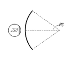
[0014] 도 5a 내지 도 5c는 곡률의 반경과 초점 반경 간의 관계들을 예시한다.
[0015] 도 6은 이미지 정보를 사용자에게 출력하기 위한 도파관 스택의 예를 예시한다.
[0016] 도 7은 도파관에 의해 출력된 출사 빔들의 예를 예시한다.
[0017] 도 8은 각각의 깊이 평면이 다수의 상이한 컴포넌트 컬러들을 사용하여 형성된 이미지들을 포함하는 스택된 도파관 어셈블리의 예를 예시한다.
[0018] 도 9a는 인-커플링 광학 엘리먼트를 각각 포함하는 스택된 도파관들의 세트의 예의 측 단면도를 예시한다.
[0019] 도 9b는 도 9a의 복수의 스택된 도파관들의 예의 사시도를 예시한다.
[0020] 도 9c는 도 9a 및 도 9b의 복수의 스택된 도파관들의 예의 하향식 평면도를 예시한다.
[0021] 도 10a는 디스플레이 시스템에 의해 제시되는 사용자 뷰잉 콘텐츠의 표현의 예를 예시한다.
[0022] 도 10b는 사용자 뷰잉 콘텐츠의 표현의 다른 예를 예시한다.
[0023] 도 11은 디스플레이 시스템의 사용자의 시야의 표현을 예시한다.
[0024] 도 12는 가상 객체와 연관된 지각된 깊이 평면을 조정하기 위한 예시적인 프로세스의 흐름도를 예시한다.
[0025] 도 13은 가상 객체와 연관된 지각된 깊이 평면을 조정하기 위한 다른 예시적인 프로세스의 흐름도를 예시한다.
[0026] 도 14는 가상 객체와 연관된 원근조절 단서들 및 양안 단서들을 조정하기 위한 예시적인 프로세스의 흐름도를 예시한다. 1 illustrates a user's view of AR through an augmented reality (AR) device.
2 illustrates an example of a wearable display system.
[0012] FIG. 3 illustrates a conventional display system for simulating three-dimensional imagery for a user.
[0013] FIG. 4 illustrates aspects of an approach for simulating three-dimensional imagery using multiple depth planes.
[0014] FIGS. 5A-5C illustrate relationships between radius of curvature and radius of focus.
6 illustrates an example of a waveguide stack for outputting image information to a user.
7 illustrates an example of outgoing beams output by a waveguide.
[0017] FIG. 8 illustrates an example of a stacked waveguide assembly including images where each depth plane is formed using a number of different component colors.
[0018] FIG. 9A illustrates a cross-sectional side view of an example of a set of stacked waveguides each including an in-coupling optical element.
[0019] FIG. 9B illustrates a perspective view of the example of the plurality of stacked waveguides of FIG. 9A.
[0020] FIG. 9C illustrates a top-down plan view of the example of the plurality of stacked waveguides of FIGS. 9A and 9B.
[0021] FIG. 10A illustrates an example of a presentation of user viewing content presented by a display system.
[0022] FIG. 10B illustrates another example of presentation of user viewing content.
11 illustrates a representation of a user's field of view of a display system.
[0024] FIG. 12 illustrates a flow diagram of an example process for adjusting a perceived depth plane associated with a virtual object.
[0025] FIG. 13 illustrates a flow diagram of another example process for adjusting a perceived depth plane associated with a virtual object.
[0026] FIG. 14 illustrates a flow diagram of an example process for adjusting accommodation cues and binocular cues associated with a virtual object.
[0027] 증강 현실 디스플레이 시스템들은 가상 콘텐츠를 사용자(또는 뷰어)에게 제시할 수 있으며, 가상 콘텐츠는 사용자의 시야 내의 공간의 3-차원 위치들에 로케이팅되는 것으로 나타난다. 가상 콘텐츠는 또한 이미지들, 그래픽들 및 디스플레이 시스템에 의해 사용자에게 제시될 수 있는 다른 시각적 콘텐츠를 포함할 수 있는 가상 객체들로서 지칭될 수 있다. 디스플레이 시스템은 사용자의 관점에서, 각각의 가상 객체가 3-차원 위치와 연관될 수 있도록 사용자로부터 별개의 깊이 또는 거리들로 상이한 가상 객체들을 제시할 수 있다. 3-차원 위치는 수평 축 상의 포지션, 수직 축 상의 포지션, 및 사용자로부터 멀어지는 깊이 축 상의 포지션에 대응할 수 있다. 사용자가 가까운 가상 객체를 보는 것으로부터, 예를 들어, 멀리 있는 가상 객체를 보는 것으로 또는 그 반대로 스위칭할 때, 이접운동(vergence) 및/또는 원근조절의 변화들이 발생할 수 있다. 아래에서 보다 상세히 설명되는 바와 같이, 이접운동은 사용자의 눈들의 지향성 움직임과 관련되고, 원근조절은 (눈들의 망막 상에 광을 포커싱하는 역할을 할 수 있는) 눈들의 동공들 및 렌즈들의 변화와 관련된다. [0027] Augmented reality display systems can present virtual content to a user (or viewer), which virtual content appears to be located at three-dimensional locations in space within the user's field of view. Virtual content can also be referred to as virtual objects, which can include images, graphics, and other visual content that can be presented to a user by a display system. The display system can present different virtual objects at distinct depths or distances from the user so that, from the user's perspective, each virtual object can be associated with a three-dimensional location. A three-dimensional position may correspond to a position on a horizontal axis, a position on a vertical axis, and a position on a depth axis away from the user. When a user switches from viewing a near virtual object to, eg, viewing a distant virtual object or vice versa, vergence and/or changes in accommodation may occur. As explained in more detail below, disjunctive motion relates to the directional movement of the user's eyes, and accommodation involves changes in the pupils and lenses of the eyes (which may serve to focus light onto the retinas of the eyes). related
[0028] 일부 실시예들에서, 사용자가 다른 가상 객체들 또는 가상 객체들 및 실제 객체들의 결합을 보는 동안 사용자의 시각 시스템이 원근조절을 변화시키고 그리고/또는 이접운동을 변화시키는 정도를 제한하도록 가상 객체들의 프리젠테이션을 조정하기 위한 기술들이 제공된다. 예를 들어, 가상 객체의 프리젠테이션은, 가상 객체에 대한 하나 또는 그 초과의 깊이 단서들과 다른 가상 객체들 또는 실제 객체들에 대한 대응하는 깊이 단서들 간의 차이가 감소되도록 조정될 수 있다. 예를 들어, 사용자의 가상 객체들에 대한 하나 또는 그 초과의 깊이 단서들은, 사용자가 바라보고 있는 다른 가상 객체들 또는 실제 객체들에 대한 대응하는 깊이 단서들과 유사하게 되도록 조정될 수 있다. 깊이 단서들은 원근조절 단서들 및/또는 양안 단서들을 포함할 수 있다. 설명될 바와 같이, 가상 객체의 원근조절 단서들을 조정하는 것은 디스플레이 시스템에 의해 사용자에게 출력되는 광의 파면 발산(wavefront divergence)을 조정하는 것을 포함할 수 있고, 양안 단서들을 조정하는 것은, 사용자의 각각의 눈에 제공되는 가상 객체의 뷰들을 조정하는 것(예를 들어, 양안 시차(binocular disparity)를 조정하는 것)을 포함할 수 있다. 가상 객체의 뷰들을 조정하는 것은 가상 객체의 양안 프리젠테이션(dichoptic presentation)들을 조정하는 것을 포함한다. 일부 실시예들에서, 사용자는 상이한 깊이들에서 제시되는 2개의 가상 객체들을 보는 것 사이에서 스위칭할 수 있고, 스위칭 후에 각각의 가상 객체에 대한 그의 원근조절성 응답(accommodative response)을 변화시킬 필요 없이 가상 객체들 각각을 편안하게 볼 수 있다. [0028] In some embodiments, virtual to limit the extent to which the user's visual system changes accommodation and/or changes vergence while the user views different virtual objects or a combination of virtual objects and real objects. Techniques are provided for adjusting the presentation of objects. For example, the presentation of a virtual object may be adjusted such that a difference between one or more depth cues for a virtual object and corresponding depth cues for other virtual objects or real objects is reduced. For example, one or more depth cues for the user's virtual objects may be adjusted to be similar to corresponding depth cues for other virtual objects or real objects the user is looking at. Depth cues may include accommodation cues and/or binocular cues. As will be explained, adjusting the accommodation cues of the virtual object may include adjusting the wavefront divergence of light output to the user by the display system, and adjusting the binocular cues may include adjusting the user's respective accommodation cues. adjusting the views of the virtual object presented to the eye (eg, adjusting for binocular disparity). Adjusting the views of the virtual object includes adjusting dichoptic presentations of the virtual object. In some embodiments, a user can switch between viewing two virtual objects presented at different depths, without having to change his accommodative response to each virtual object after switching. Each of the virtual objects can be comfortably viewed.
[0029] 본원에서 설명된 기술들을 활용하여, 가상 콘텐츠의 지각된 프리젠테이션 품질이 개선될 수 있다. 예를 들어, 본원에서 추가로 설명된 바와 같이, 상이한 깊이 평면들 사이에서 콘텐츠를 스위칭함으로써 야기되는 깜박거림(flicker)과 같은 지각 가능한 시각적 아티팩트들은 특히, 소정의 증강 현실 디스플레이 시스템들이 예를 들어, 가변-초점(vari-focal) 디스플레이 시스템들로서 활용될 때 감소될 수 있다. 다른 예로서, 가상 객체와 다른 가상 또는 실제 객체 사이의 응시(fixation)의 신속한 스위칭은 사용자가 이들 객체들 간의 원근조절을 변화시킬 필요성을 감소시킴으로써 용이해 질 수 있다. 예를 들어, 사용자의 눈들이 포커싱함에 따라, 원근조절의 변화는 지각 가능할만한 양의 시간이 걸릴 수 있고, 이러한 지각 가능할만한 양의 시간은 예를 들어, 2개의 객체들 사이에서 사용자가 자신의 주의(attention)를 반복적으로 스위칭할 때 정보를 흡수하는 사용자의 능력을 느려지게 함으로써 사용자 경험을 저하시킬 수 있다. 예를 들어, 빠른 사용자 반응들이 경쟁적인 플레이(competitive play)의 기반인 게임들과 같은 맥락에서 이러한 느려짐은 바람직하지 않을 수 있다. 다른 맥락들의 예들은 멀티태스킹 및/또는 높은 수준의 집중이 필요한 빨리 진행되는 환경들, 예를 들어, 수술실들을 포함한다. [0029] Utilizing the techniques described herein, the perceived presentation quality of virtual content may be improved. For example, as described further herein, perceptible visual artifacts such as flicker caused by switching content between different depth planes are, in particular, certain augmented reality display systems, for example, may be reduced when utilized as vari-focal display systems. As another example, rapid switching of fixation between a virtual object and another virtual or real object may be facilitated by reducing the need for the user to change accommodation between these objects. For example, as the user's eyes focus, the change in accommodation can take a perceptible amount of time, and this perceptible amount of time is such that the user moves between two objects, for example. Switching attention repeatedly can degrade the user experience by slowing the user's ability to absorb information. This slowdown may be undesirable, for example, in the context of games where fast user responses are the basis for competitive play. Examples of other contexts include fast-paced environments requiring multitasking and/or a high degree of concentration, eg, operating rooms.
[0030] 가변 초점 디스플레이 시스템과 관련하여, 이러한 시스템들은 이산 깊이 평면들에서 가상 콘텐츠를 제시할 수 있으며, 모든 가상 콘텐츠는 사용자에게 제시된 각각의 프레임에 대해 동일한 깊이 평면에 제시된다(예를 들어, 한 번에 단지 하나의 깊이 평면만이 활성이거나 또는 이미지 정보를 출력함)는 것이 인지될 것이다. 설명된 바와 같이, 가변-초점 디스플레이 시스템은 사용자가 응시하고 있는 3-차원 응시 지점을 결정할 수 있고, 응시 지점에 기초하여 모든 가상 콘텐츠를 제시할 깊이 평면을 선택할 수 있다. 응시 지점을 결정하는 예로서, 디스플레이 시스템은 사용자의 눈들의 배향들 및/또는 형상들을 모니터링하고 각각의 결정된 눈의 시선들이 교차하는 3-차원 위치를 결정할 수 있다. 디스플레이 시스템은 사용자가 특정 3-차원 위치에서 제시되는 특정 가상 객체를 보고 있다고 결정할 수 있고, 디스플레이 시스템은 3-차원 위치에 대응하는 깊이 평면에서 모든 가상 콘텐츠를 제시할 수 있다. 이러한 방식으로, 디스플레이 시스템은 특정 가상 객체, 및 선택적으로 다른 가상 콘텐츠가 사용자에게 인 포커스라는 것을 보장할 수 있다. 후속적으로 선택된 깊이 평면에서 가상 콘텐츠를 제시할 때, 예로서, 디스플레이 시스템이 후속적으로 선택된 깊이 평면에서 가상 콘텐츠를 제시하도록 스위칭하고 이전의 깊이 평면으로 다시 되돌아옴에 따라 지각 가능한 깜박거림이 도입될 수 있다. 예를 들어, 사용자가 후속적인 응시 지점을 응시하도록 자신의 눈들을 수정함에 따라, 디스플레이 시스템은 후속적으로 제시되는 프레임에서 가상 콘텐츠를 제시하도록 후속하는 깊이 평면을 선택할 수 있다. 깊이 평면들 사이의 계면 근처의 응시 지점 및/또는 상기 응시 지점을 결정하는 데 있어 에러들은 깊이 평면들 사이에서 왔다갔다하는(back and forth) 원하지 않는 그리고/또는 랜덤 스위칭을 야기할 수 있다. 도 11과 관련하여 아래에서 설명될 바와 같이, 각각의 깊이 평면은 사용자로부터의 특정 깊이 범위를 포함할 수 있어서, 사용자의 눈들이 응시하고 있는 3-차원 위치에 따라 깊이 평면이 선택될 수 있다. [0030] With respect to variable focus display systems, such systems can present virtual content in discrete depth planes, with all virtual content being presented in the same depth plane for each frame presented to the user (e.g., It will be appreciated that only one depth plane is active or outputting image information at a time. As described, the variable-focus display system can determine the three-dimensional gaze point at which the user is gazing and, based on the gaze point, can select a depth plane to present all virtual content. As an example of determining the point of gaze, the display system may monitor the orientations and/or shapes of the user's eyes and determine the three-dimensional location at which the gaze lines of each determined eye intersect. The display system can determine that the user is looking at a particular virtual object presented at a particular three-dimensional location, and the display system can present all virtual content in a depth plane corresponding to the three-dimensional location. In this way, the display system can ensure that certain virtual objects, and optionally other virtual content, are in focus to the user. When presenting virtual content at a subsequently selected depth plane, a perceptible flicker may be introduced, eg, as the display system switches to presenting virtual content at the subsequently selected depth plane and back again to the previous depth plane. can For example, as the user modifies their eyes to gaze at subsequent gaze points, the display system may select subsequent depth planes to present virtual content in subsequently presented frames. A point of gaze near an interface between depth planes and/or errors in determining the point of gaze may cause unwanted and/or random switching back and forth between depth planes. As will be described below with respect to FIG. 11 , each depth plane can include a specific depth range from the user, such that a depth plane can be selected depending on the three-dimensional location at which the user's eyes are gazing.
[0031] 이산 깊이 평면들에서 가상 콘텐츠를 제시하기 위해, 디스플레이 시스템은 상이한 깊이 평면들에 대응하는 상이한 파면 발산을 갖는 광을 출력하도록 구성된 하나 또는 그 초과의 도파관들을 포함할 수 있다. 상이한 파면 발산들을 사용하여, 상이한 원근조절 단서들이 사용자에게 제공될 수 있고, 디스플레이 시스템은, (상이한 파면 발산을 갖는 광을 사용하여) 제2 가상 객체가 사용자의 시야에서 제2 깊이에 로케이팅되는 것으로 나타나게 하면서, 제1 가상 객체가 사용자의 시야에서 제1 깊이에 로케이팅되는 것으로 나타나게 할 수 있다. 부가적으로, 디스플레이 시스템은 사용자의 각각의 눈에 상이한 이미지들을 제시할 수 있고; 예를 들어, 디스플레이 시스템은 가상 객체의 약간 상이한 뷰들을 각각의 눈에 제시하는 양안 디스플레이일 수 있고, 각각의 뷰는 주어진 깊이 평면에서 각각의 개별 눈에 의한 가상 객체의 뷰에 대응한다. 즉, 디스플레이 시스템은, 깊이가 양안 시차를 통해 부분적으로 표현될 수 있도록 가상 객체의 양안 프리젠테이션들을 눈들에 제공할 수 있다. 따라서, 가상 객체는 각각의 눈에 제공되는 가상 객체의 상이한 뷰들 및 출력 파면 발산에 기초하여 상이한 깊이들에 존재하는 것으로서 사용자에 의해 지각될 수 있다. [0031] To present virtual content at discrete depth planes, a display system may include one or more waveguides configured to output light with different wavefront divergence corresponding to different depth planes. Using different wavefront divergence, different accommodation cues can be provided to the user, and the display system determines (using light having a different wavefront divergence) that the second virtual object is located at a second depth in the user's field of view. , the first virtual object may appear to be located at a first depth in the user's field of view. Additionally, the display system can present different images to each eye of the user; For example, the display system may be a binocular display presenting each eye with slightly different views of the virtual object, each view corresponding to a view of the virtual object by each individual eye at a given depth plane. That is, the display system may provide binocular presentations of a virtual object to the eyes such that depth may be expressed in part through binocular parallax. Thus, a virtual object may be perceived by a user as existing at different depths based on the output wavefront divergence and the different views of the virtual object presented to each eye.
[0032] 따라서, 위에서 설명된 바와 같이, 가변-초점 디스플레이 시스템은 각각의 프레임에 대한 특정 파면 발산(특정 깊이 평면에 대응함)을 사용하여 모든 가상 콘텐츠를 제시할 수 있다. 사용자가 자신의 응시 지점을 수정함에 따라, 상이한 파면 발산을 갖는 광이 다른 깊이 평면들 상에 다른 가상의 콘텐츠를 제시하도록 선택될 수 있다. 상이한 깊이 평면들 상의 2개의 객체들 간에 응시를 스위칭하는 사용자는, 깊이 평면들 사이에서 신속하고 반복적인 스위칭(이는 상이한 깊이 평면들이 상이한 시간들에 활성이 될 때 깜박거림으로서 사용자에 의해 지각될 수 있음)을 야기할 수 있다는 것이 인지될 것이다. 또한, 본원에서 언급된 바와 같이, 사용자의 눈들의 원근조절이 변함에 따라 사용자가 콘텐츠를 보는 데 있어 순간적인 랙(momentary lag)이 있을 수 있다. [0032] Thus, as described above, a variable-focus display system can present all virtual content using a particular wavefront divergence (corresponding to a particular depth plane) for each frame. As the user modifies his point of gaze, light with different wavefront divergence may be selected to present different virtual content on different depth planes. A user switching gaze between two objects on different depth planes is a rapid and repetitive switching between depth planes (this can be perceived by the user as a flicker when different depth planes become active at different times). It will be appreciated that it can cause Also, as noted herein, there may be a momentary lag in the user viewing content as the accommodation of the user's eyes changes.
[0033] 본원에서 설명된 기술들은 유리하게는, 사용자의 원근조절에서의 디스플레이 시스템 개시 변화들 및/또는 깊이 평면 스위칭에 의해 야기되는, 콘텐츠를 보는데 있어서의 랙 및/또는 깜박거림의 발생을 감소시키는데 활용될 수 있다. 디스플레이 시스템은 다양한 가상 객체들이 3-차원 공간에 배치될 수 있는 곳을 표시하는 맵 또는 데이터베이스에 대한 액세스를 가질 수 있다는 것이 인지될 것이다. 일부 실시예들에서, 디스플레이 시스템은 사용자가 제1 가상 객체와, (1) 제1 가상 객체와 상이한(예를 들어, 더 멀거나 더 근접한) 깊이 평면에 로케이팅되는 제2 가상 객체 또는 (2) 실세계 객체를 보는 것 사이에서 스위칭하고 있다고 결정할 수 있다. 그 후, 디스플레이 시스템은 객체들이 동일한 깊이 평면에서 제시되게 할 수 있다. 예를 들어, 디스플레이 시스템은 사용자가 제1 가상 객체 또는 제2 가상 객체를 응시하는지 여부와 무관하게, 제1 가상 객체 및 제2 가상 객체가 (예를 들어, 동일한 도파관을 통해 제시되는) 동일하거나 유사한 파면 발산들로 출력되게 할 수 있다. 부가적으로, 디스플레이 시스템은 제1 가상 객체가 실세계 객체의 깊이와 연관된 파면 발산으로 출력되게 할 수 있다. 일부 다른 실시예들에서, 디스플레이 시스템은 사용자가 응시하고 있는 깊이 평면을 결정하고, 제1 인스턴스에서 가상 콘텐츠를 출력하기 전에 디스플레이 시스템의 맵에 의해 표시된 깊이 평면을 수정할 수 있다. [0033] The techniques described herein advantageously reduce the occurrence of lag and/or flickering in viewing content caused by display system initiated changes in a user's accommodation and/or depth plane switching. can be used to do it. It will be appreciated that the display system may have access to a map or database indicating where various virtual objects may be placed in three-dimensional space. In some embodiments, the display system allows a user to interact with a first virtual object, (1) a second virtual object that is located in a depth plane that is different (eg, farther or closer) to the first virtual object, or (2) ) may decide that it is switching between viewing real-world objects. The display system can then cause objects to be presented in the same depth plane. For example, the display system may determine whether the first virtual object and the second virtual object are the same (eg, presented through the same waveguide), regardless of whether the user gazes at the first virtual object or the second virtual object. It can be output with similar wavefront divergence. Additionally, the display system may cause the first virtual object to be output with a wavefront divergence associated with the depth of the real world object. In some other embodiments, the display system may determine the depth plane the user is gazing at and, in the first instance, modify the depth plane indicated by the map of the display system prior to outputting the virtual content.
[0034] 일부 실시예들에서, 디스플레이 시스템은, 가상 객체가 각각의 눈에 제공되는 가상 객체의 뷰들을 유지(예를 들어, 조정하지 않음)하면서 다른 가상 객체 또는 실제 객체로서 (동일한 깊이 평면에 대응하는) 동일한 파면 발산으로 제시되도록 출력 파면 발산을 조정함으로써 사용자의 원근조절 응답의 스위칭을 감소시킬 수 있다. 이론에 의해 제한됨 없이, 가상 객체의 뷰들이 수정되지 않기 때문에, 3-차원 공간에서 지각된 위치는 양안 단서들(예를 들어, 양안 시차)에 기초하여 보존될 수 있다. 결과적으로, 원근조절의 변화들을 회피하면서 지각된 3-차원 위치가 유지될 수 있다. 그러나, 그리고 설명될 바와 같이, 각각의 눈에 제시된 가상 객체의 동일한 뷰들을 유지하면서 가상 객체의 파면 발산을 수정하는 것은 수정된 파면 발산과 연관된 지각된 깊이와 양안 시차와 연관된 지각된 깊이 간의 미스매치(mismatch)로 인한 부정적인 생리학적 응답들(예를 들어, 두통들, 눈의 피로, 피로감 등)을 초래할 수 있다. 양안 시차와 연관된 (예를 들어, 디옵터 단위의) 지각된 깊이와 특정 파면 발산과 연관된 (예를 들어, 디옵터 단위의) 지각된 깊이는 디스플레이 시스템에 의해 결정될 수 있고, 이들 두 값들 사이의 미스매치는 원근조절 이접운동 미스매치를 결정하기 위해 계산될 수 있다. 일부 실시예들에서, 미스매치가 임계치(예를 들어, 0.33 디옵터)보다 큰 경우, 디스플레이 시스템은 (출력 파면 발산을 수정하는 것 외에도) 부가적인 액션들을 수행할 수 있다. 예로서, 디스플레이 시스템은 양안 시차를 조정하여, 예를 들어, 파면 발산과 연관된 깊이 평면에 대응하도록 각각의 눈에 제공되는 가상 객체의 뷰들을 수정한다. [0034] In some embodiments, the display system may be configured (in the same depth plane) as another virtual object or real object, while maintaining (eg, not adjusting) the views of the virtual object that the virtual object is presented to each eye. Adjusting the output wavefront divergence so that it is presented with the corresponding (corresponding) equal wavefront divergence can reduce the switching of the user's accommodation response. Without being bound by theory, since the views of the virtual object are not modified, the perceived position in 3-dimensional space may be preserved based on binocular cues (eg, binocular parallax). As a result, the perceived three-dimensional position can be maintained while avoiding changes in accommodation. However, and as will be explained, correcting the wavefront divergence of a virtual object while maintaining identical views of the virtual object presented to each eye results in a mismatch between the perceived depth associated with the corrected wavefront divergence and the perceived depth associated with binocular parallax. mismatch can lead to negative physiological responses (eg headaches, eye strain, fatigue, etc.). The perceived depth associated with binocular parallax (eg, in diopters) and the perceived depth associated with a particular wavefront divergence (eg, in diopters) may be determined by the display system, and a mismatch between these two values can be calculated to determine accommodation dislocation mismatch. In some embodiments, if the mismatch is greater than a threshold (eg, 0.33 diopters), the display system may perform additional actions (besides correcting the output wavefront divergence). As an example, the display system adjusts binocular parallax to modify the views of the virtual object presented to each eye to correspond to, eg, a depth plane associated with wavefront divergence.
[0035] 선택적으로, 디스플레이 시스템은 가상 객체의 파면 발산을 수정함 없이, 가상 객체의 양안 시차를 조정할 수 있다. 즉, 사용자가 가상 객체들에 대해 원근조절하는 빈도를 제한하기 위해 파면 발산을 조정하는 디스플레이 시스템과 대조적으로, 디스플레이 시스템은 가상 객체들이 다른 객체들과 동일하거나 유사한 깊이 평면에 있는 것으로 지각되도록 양안 시차를 조정할 수 있다. [0035] Optionally, the display system may adjust the binocular parallax of the virtual object without modifying the wavefront divergence of the virtual object. That is, in contrast to a display system that adjusts wavefront divergence to limit the frequency at which the user accommodates to virtual objects, the display system is binocular parallax such that virtual objects are perceived to be in the same or similar depth plane as other objects. can be adjusted.
[0036] 가변-초점 디스플레이 시스템들이 위의 부분들에서 설명되었지만, 본원에서 다중-초점 디스플레이 시스템들로서 지칭되는 다른 디스플레이 시스템들이 활용될 수 있다. 다중 초점 디스플레이 시스템은, 사용자에게 제시된 각각의 프레임에 대한 다수의 깊이 평면들 상에서 콘텐츠가 동시에 디스플레이되도록 다수의 상이한 깊이 평면들과 연관된 파면 발산을 갖는 광을 동시에 출력할 수 있다. 다중-초점 디스플레이 시스템은 동일한 프레임의 상이한 깊이 평면들에 가상 객체들을 제시할 수 있으므로, 다중-초점 디스플레이 시스템은 사용자가 자신의 뷰를 다른 가상 객체들로 스위칭할 때 소정의 시각적 아티팩트들(예를 들어, 깜박거림)을 도입하는 것을 회피할 수 있다. 그러나, 가상 객체가 제시되는 깊이 평면을 조정하는 것과 같이, 본원에서 설명된 기술들을 활용하면 위의 설명과 부합하여 원근조절을 변화시킬 필요성이 감소될 수 있다. [0036] Although variable-focus display systems have been described in the sections above, other display systems, referred to herein as multi-focus display systems, may be utilized. A multifocal display system can simultaneously output light with wavefront divergence associated with multiple different depth planes such that content is simultaneously displayed on multiple depth planes for each frame presented to a user. Because the multi-focus display system can present virtual objects at different depth planes in the same frame, the multi-focus display system avoids certain visual artifacts (eg, For example, blinking) can be avoided. However, utilizing the techniques described herein, such as adjusting the depth plane on which virtual objects are presented, may reduce the need to change accommodations consistent with the description above.
[0037] 디스플레이 시스템은 증강 현실 디스플레이 시스템 또는 가상 현실 디스플레이 시스템의 일부일 수 있다는 것이 인지될 것이다. 일 예로서, 디스플레이 시스템은 투과성일 수 있으며, 사용자에게 이미지들, 비디오, 상호작용(interactivity) 등의 형태로 가상 콘텐츠를 제공하면서 사용자가 실세계를 보도록 허용할 수 있다. 다른 예로서, 디스플레이 시스템은 실세계의 사용자의 뷰를 차단할 수 있으며, 가상 현실 이미지들, 비디오, 상호작용 등이 사용자에게 제시될 수 있다. [0037] It will be appreciated that the display system may be part of an augmented reality display system or a virtual reality display system. As an example, the display system may be transmissive and allow the user to view the real world while presenting virtual content to the user in the form of images, video, interactivity, and the like. As another example, the display system can block the user's view of the real world, and virtual reality images, video, interactions, and the like can be presented to the user.
[0038] 또한, 본원에서 설명된 다양한 실시예들은 유리하게는, 다양한 맥락들에서 적용될 수 있다는 것이 인지될 것이다. 예로서, 본원에서 개시된 기술들 및 시스템들은 가상 객체들이 실제 객체들과 관련하여 보여질 수 있는 건강관리 맥락들에서 적용될 수 있다. 예를 들어, 외과의사는 디스플레이 시스템을 착용하면서 실생활 환자를 수술할 수 있다. 디스플레이 시스템은 유리하게는, 심박수 정보와 같은 의료 정보를 외과의사에게 제시할 수 있다. 디스플레이 시스템은 외과의사가 자신의 임무들을 수행하는 동안 외과의사가 환자와 의료 정보 사이에서 원근조절을 스위칭해야 할 필요성을 회피할 수 있도록 환자에 가장 가까운 깊이 평면에 의료 정보가 제시되게 할 수 있다. 다른 예로서, 사용자는 디스플레이 시스템을 착용하면서 경주용 자동차 운전 게임을 플레이하고 있을 수 있다. 디스플레이 시스템은 사용자의 자동차의 내부 및 자동차의 외부(예를 들어, 도로, 경쟁자 자동차들)와 같은 가상 콘텐츠를 제시할 수 있다. 디스플레이 시스템은 자동차의 외부 또는 경쟁자의 자동차와 동일한 깊이 평면(예를 들어, 자동차의 전면유리를 통한 시야) 상에 제시되도록 속도계와 같은 특정 가상 콘텐츠를 조정할 수 있다. 이러한 방식으로, 사용자는, 사용자가 자동차의 질주를 바라보고 속도계를 볼 때마다 속도계에 대한 원근조절을 변화시킬 필요성을 회피하면서 자신의 속도를 쉽고 빠르게 볼 수 있다. 또한, 깜박거림은 사용자가 속도계를 보는 동안 제거될 수 있으며, 그렇지 않았으면, 이는 게임 플레이에 부정적인 영향을 미쳤을 수 있다. [0038] It will also be appreciated that the various embodiments described herein may be advantageously applied in a variety of contexts. As an example, the techniques and systems disclosed herein may be applied in healthcare contexts in which virtual objects may be viewed in relation to real objects. For example, a surgeon can operate on a real-life patient while wearing the display system. The display system can advantageously present medical information, such as heart rate information, to a surgeon. The display system may allow medical information to be presented in a depth plane closest to the patient so that the surgeon can avoid the need to switch accommodation between the patient and the medical information while the surgeon performs his duties. As another example, a user may be playing a racing car driving game while wearing the display system. The display system can present virtual content, such as inside the user's car and outside the car (eg, road, competitor's cars). The display system may adjust certain virtual content, such as a speedometer, to be presented outside the car or on the same depth plane as a competitor's car (eg, view through the car's windshield). In this way, the user can easily and quickly view his own speed while avoiding the need to change accommodations to the speedometer each time the user looks at the speedometer as he watches the car gallop. Also, the flicker can be eliminated while the user is looking at the speedometer, which would otherwise negatively affect game play.
이제 도면들에 대한 참조가 이루어질 것이다. Reference will now be made to the drawings.
[0039] 도 2는 착용 가능 디스플레이 시스템(60)의 예를 예시한다. 디스플레이 시스템(60)은 디스플레이(70), 및 그 디스플레이(70)의 기능을 지원하기 위한 다양한 기계적 및 전자적 모듈들 및 시스템들을 포함한다. 디스플레이(70)는, 디스플레이 시스템 사용자 또는 뷰어(90)에 의해 착용 가능하고 그리고 사용자(90)의 눈들의 전면에 디스플레이(70)를 포지셔닝하도록 구성된 프레임(80)에 커플링될 수 있다. 디스플레이(70)는 일부 실시예들에서, 아이웨어(eyewear)로 간주될 수 있다. 일부 실시예들에서, 스피커(100)는 프레임(80)에 커플링되고 사용자(90)의 외이도에 인접하게 포지셔닝되도록 구성된다(일부 실시예들에서, 도시되지 않은 다른 스피커가 선택적으로, 사용자의 다른 외이도에 인접하게 포지셔닝되어 스테레오/형상화 가능(shapeable) 사운드 제어를 제공할 수 있음). 디스플레이 시스템은 또한 하나 또는 그 초과의 마이크로폰들(110) 또는 사운드를 검출하기 위한 다른 디바이스들을 포함할 수 있다. 일부 실시예들에서, 마이크로폰은 사용자가 시스템(60)에 입력들 또는 커맨드들(예를 들어, 음성 메뉴 커맨드들의 선택, 자연어 질문 등)을 제공하도록 허용하게 구성되고, 그리고/또는 다른 사람들(예를 들어, 유사한 디스플레이 시스템들의 다른 사용자들)과의 오디오 통신을 허용할 수 있다. 마이크로폰은 또한, 오디오 데이터(예를 들어, 사용자 및/또는 환경으로부터의 사운드들)를 수집하기 위한 주변 센서로서 구성될 수 있다. 일부 실시예들에서, 디스플레이 시스템은 또한, 프레임(80)과 별개이고 사용자(90)의 신체(예를 들어, 사용자(90)의 머리, 몸통, 손발(extremity) 등)에 부착될 수 있는 주변 센서(120a)를 포함할 수 있다. 주변 센서(120a)는 일부 실시예들에서, 사용자(90)의 생리학적 상태를 특징화하는 데이터를 취득하도록 구성될 수 있다. 예를 들어, 센서(120a)는 전극일 수 있다. 2 illustrates an example of a
[0040] 도 2를 계속 참조하면, 디스플레이(70)는, 다양한 구성들로 장착될 수 있는, 예컨대, 프레임(80)에 고정되게 부착되거나, 사용자에 의해 착용된 헬멧 또는 모자에 고정되게 부착되거나, 헤드폰들에 내장되거나, 그렇지 않으면 사용자(90)에게 제거 가능하게 부착되는(예를 들어, 백팩(backpack)-스타일 구성으로, 벨트-커플링 스타일 구성으로) 로컬 데이터 프로세싱 모듈(140)에 통신 링크(130)에 의해, 예컨대, 유선 리드 또는 무선 연결성에 의해, 동작 가능하게 커플링된다. 유사하게, 센서(120a)는 통신 링크(120b), 예를 들어, 유선 리드 또는 무선 연결성에 의해 로컬 프로세서 및 데이터 모듈(140)에 동작 가능하게 커플링될 수 있다. 로컬 프로세싱 및 데이터 모듈(140)은 하드웨어 프로세서뿐 아니라, 디지털 메모리 예컨대, 비-휘발성 메모리(예를 들어, 플래시 메모리 또는 하드 디스크 드라이브들)를 포함할 수 있고, 이 둘 모두는 데이터의 프로세싱, 캐싱(caching) 및 저장을 보조하기 위해 활용될 수 있다. 선택적으로, 로컬 프로세서 및 데이터 모듈(140)은 하나 또는 그 초과의 CPU(central processing unit)들, GPU(graphics processing unit)들, 전용 프로세싱 하드웨어 등을 포함할 수 있다. 데이터는 a) 센서들(예를 들어 프레임(80)에 동작 가능하게 커플링되거나 그렇지 않으면 사용자(90)에게 부착될 수 있음), 예컨대, 이미지 캡처 디바이스들(예컨대, 카메라들), 마이크로폰들, 관성 측정 유닛들, 가속도계들, 컴파스(compass)들, GPS 유닛들, 라디오 디바이스들, 자이로(gyro)들 및/또는 본원에서 개시된 다른 센서들로부터 캡처되고; 및/또는 b) 원격 프로세싱 모듈(150) 및/또는 원격 데이터 리포지토리(repository)(160)(가상 콘텐츠에 관련된 데이터를 포함함)를 사용하여 취득 및/또는 프로세싱되는(가능하게는, 이러한 프로세싱 또는 리트리벌(retrieval) 후 디스플레이(70)에 전달하기 위한) 데이터를 포함할 수 있다. 로컬 프로세싱 및 데이터 모듈(140)은 통신 링크들(170, 180)에 의해, 예컨대, 유선 또는 무선 통신 링크들을 통하여, 원격 프로세싱 모듈(150) 및 원격 데이터 리포지토리(160)에 동작 가능하게 커플링될 수 있어서, 이들 원격 모듈들(150, 160)은 서로 동작 가능하게 커플링되고 로컬 프로세싱 및 데이터 모듈(140)에 대한 자원들로서 이용 가능하다. 일부 실시예들에서, 로컬 프로세싱 및 데이터 모듈(140)은 이미지 캡처 디바이스들, 마이크로폰들, 관성 측정 유닛들, 가속도계들, 컴파스들, GPS 유닛들, 라디오 디바이스들 및/또는 자이로들 중 하나 또는 그 초과를 포함할 수 있다. 일부 다른 실시예들에서, 이들 센서들 중 하나 또는 그 초과는 프레임(80)에 부착될 수 있거나, 또는 유선 또는 무선 통신 통로들에 의해 로컬 프로세싱 및 데이터 모듈(140)과 통신하는 자립형 구조들일 수 있다. [0040] With continued reference to FIG. 2,
[0041] 도 2를 계속 참조하면, 일부 실시예들에서, 원격 프로세싱 모듈(150)은, 예를 들어, 하나 또는 그 초과의 CPU(central processing unit)들, GPU(graphics processing unit)들, 전용 프로세싱 하드웨어 등을 포함하는, 데이터 및/또는 이미지 정보를 분석 및 프로세싱하도록 구성된 하나 또는 그 초과의 프로세서들을 포함할 수 있다. 일부 실시예들에서, 원격 데이터 리포지토리(160)는 "클라우드" 자원 구성에서 인터넷 또는 다른 네트워킹 구성을 통하여 이용 가능할 수 있는 디지털 데이터 저장 설비를 포함할 수 있다. 일부 실시예들에서, 원격 데이터 리포지토리(160)는 정보, 예를 들어, 증강 현실 콘텐츠를 생성하기 위한 정보를 로컬 프로세싱 및 데이터 모듈(140) 및/또는 원격 프로세싱 모듈(150)에 제공하는 하나 또는 그 초과의 원격 서버들을 포함할 수 있다. 일부 실시예들에서, 모든 데이터는 저장되고 모든 컴퓨테이션들은 로컬 프로세싱 및 데이터 모듈에서 수행되어, 원격 모듈로부터 완전히 자율적인 사용을 허용한다. 선택적으로, CPU들, GPU들 등을 포함하는 외부 시스템(예를 들어, 하나 또는 그 초과의 프로세서들의 시스템, 하나 또는 그 초과의 컴퓨터들)은 프로세싱 중 적어도 일부(예를 들어, 이미지 정보의 생성, 데이터의 프로세싱)를 수행하고 예를 들어, 무선 또는 유선 연결들을 통해 모듈들(140, 150, 160)에 정보를 제공하고 이들로부터 정보를 수신할 수 있다. [0041] With continued reference to FIG. 2, in some embodiments,
[0042] 이제 도 3을 참조하면, "3-차원" 또는 "3-D"로서 이미지의 지각은 뷰어의 각각의 눈에 이미지의 약간 상이한 프리젠테이션들을 제공함으로써 달성될 수 있다. 도 3은 사용자에 대한 3차원 이미저리(imagery)를 시뮬레이팅하기 위한 종래의 디스플레이 시스템을 예시한다. 각각의 눈(210, 220)에 대해 하나씩 2개의 별개의 이미지들(190, 200)이 사용자에게 출력되어, 깊이의 지각을 유도하기 위해 사용자의 시각 시스템이 해석할 수 있는 양안 단서들을 제공한다. 이미지들(190, 200)은 뷰어의 시선과 평행한 광학 또는 z-축을 따라 거리(230) 만큼 눈들(210, 220)로부터 이격된다. 이미지들(190, 200)은 편평하고 눈들(210, 220)은 단일 원근조절된 상태를 가정함으로써 이미지들을 포커싱할 수 있다. 그러한 3-D 디스플레이 시스템들은 결합된 이미지에 대한 스케일 및/또는 깊이의 지각을 제공하기 위하여 이미지들(190, 200)을 결합하는 데 인간 시각 시스템에 의존한다. [0042] Referring now to FIG. 3, the perception of an image as "three-dimensional" or "3-D" may be achieved by providing slightly different presentations of the image to each eye of a viewer. 3 illustrates a conventional display system for simulating three-dimensional imagery for a user. Two
[0043] 그러나, 인간 시각 시스템은 더 복잡하고 현실적인 깊이의 지각을 제공하는 것이 더 어렵다는 것이 인지될 것이다. 예를 들어, 종래의 "3-D" 디스플레이 시스템들의 많은 뷰어들은 그런 시스템들이 불편하다는 것을 발견하거나, 깊이 감을 전혀 지각하지 못할 수 있다. 이론에 의해 제한됨이 없이, 객체의 뷰어들은 이접운동 및 원근조절의 결합으로 인해 객체를 "3-차원"인 것으로 지각할 수 있다고 여겨진다. 서로에 대한 2개의 눈들의 이접운동 움직임들(예를 들어, 객체를 응시하도록 눈들의 시선들을 폭주(converge)시키기 위하여 서로를 향해 또는 서로 멀어지게 동공들이 움직이도록 하는 눈들의 로테이션(rotation))은 눈들의 동공들 및 렌즈들의 포커싱(또는 "원근조절")과 밀접하게 연관된다. 정상 조건들하에서, 상이한 거리에 있는 하나의 객체로부터 다른 객체로 포커스를 변화시키기 위하여, 눈들의 렌즈들의 포커스를 변화시키거나, 또는 눈들을 원근조절하는 것은 동공 팽창 또는 수축은 물론, "원근조절-이접운동 반사(accommodation-vergence reflex)"로서 알려진 관계하에서, 동일한 거리에 대한 이접운동에서의 매칭하는 변화를 자동으로 유발할 것이다. 마찬가지로, 이접운동에서의 변화는 정상 조건들하에서, 렌즈 형상 및 동공 크기의, 원근조절에서의 매칭하는 변화를 트리거할 것이다. 본원에서 언급되는 바와 같이, 다수의 스테레오스코픽 또는 "3-D" 디스플레이 시스템들은, 3-차원 원근투시가 인간 시각 시스템에 의해 지각되도록 각각의 눈에 약간 상이한 프리젠테이션들(그리고 따라서, 약간 상이한 이미지들)을 사용하여 장면을 디스플레이한다. 그러나, 그러한 시스템들은 많은 뷰어들에게 불편한데, 그 이유는 다른 것들 중에서, 그러한 시스템들이 단순히 장면의 상이한 프리젠테이션들을 제공하지만, 눈들이 단일 원근조절된 상태에서 모든 이미지 정보를 보고, 그리고 "원근조절-이접운동 반사"에 반하여 작동하기 때문이다. 원근조절과 이접운동 간의 더 양호한 매칭을 제공하는 디스플레이 시스템들은 3-차원 이미저리의 더 현실적이고 편안한 시뮬레이션들을 형성할 수 있다. [0043] However, it will be appreciated that the human visual system is more complex and more difficult to provide realistic depth perception. For example, many viewers of conventional “3-D” display systems find such systems uncomfortable, or may not perceive a sense of depth at all. Without being limited by theory, it is believed that viewers of an object may perceive the object as being “three-dimensional” due to a combination of disjunction and accommodation. Disjunctive movements of the two eyes relative to each other (e.g., rotation of the eyes to move the pupils toward or away from each other to converge the gazes of the eyes to gaze at an object) It is closely related to the focusing (or “accommodation”) of the pupils and lenses of the eyes. Under normal conditions, changing the focus of the lenses of the eyes, or accommodating the eyes, to change the focus from one object at a different distance to another, can cause pupil dilation or constriction as well as "accommodation- Under a relationship known as the "accommodation-vergence reflex", it will automatically cause a matching change in vergence over the same distance. Similarly, a change in disjunctive motion will trigger a matching change in accommodation, of lens shape and pupil size, under normal conditions. As referred to herein, a number of stereoscopic or “3-D” display systems provide slightly different presentations to each eye (and, therefore, slightly different images) such that three-dimensional perspective is perceived by the human visual system. ) to display the scene. However, such systems are inconvenient for many viewers because, among other things, such systems simply provide different presentations of a scene, but the eyes see all image information in a single accommodation, and "accommodation- This is because it works against the disjunctive reflex. Display systems that provide better matching between accommodation and displacement can create more realistic and comfortable simulations of three-dimensional imagery.
[0044] 도 4는 다중 깊이 평면들을 사용하여 3-차원 이미저리를 시뮬레이팅하기 위한 접근법의 양상들을 예시한다. 도 4를 참조하면, z-축 상에서 눈들(210, 220)로부터의 다양한 거리들에 있는 객체들은, 이들 객체들이 인 포커싱(in focus)되도록 눈들(210, 220)에 의해 원근조절된다. 눈들(210, 220)은 z-축을 따라 상이한 거리들에 있는 객체들에 포커싱을 맞추게 하는 특정 원근조절된 상태들을 가정한다. 결과적으로, 특정 원근조절된 상태는 연관된 초점 거리를 갖는, 깊이 평면들(240) 중 특정 하나의 깊이 평면과 연관되는 것으로 말해질 수 있어서, 특정 깊이 평면의 객체들 또는 객체들의 부분들은, 눈이 해당 깊이 평면에 대해 원근조절된 상태에 있을 때 인 포커싱된다. 일부 실시예들에서, 3-차원 이미저리는 눈들(210, 220) 각각에 대해 이미지의 상이한 프리젠테이션들을 제공함으로써, 그리고 또한 깊이 평면들 각각에 대응하는 이미지의 상이한 프리젠테이션들을 제공함으로써 시뮬레이팅될 수 있다. 예시의 명확성을 위해 별개인 것으로 도시되지만, 눈들(210, 220)의 시야들은 예를 들어, z-축을 따른 거리가 증가함에 따라 겹쳐질 수 있다는 것이 인지될 것이다. 게다가, 예시의 용이함을 위해 평평한 것으로 도시되지만, 깊이 평면의 윤곽들은 물리적 공간에서 만곡될 수 있어서, 깊이 평면의 모든 피처들은 특정 원근조절된 상태에서 눈과 인 포커싱된다는 것이 인지될 것이다. [0044] FIG. 4 illustrates aspects of an approach for simulating 3-dimensional imagery using multiple depth planes. Referring to Figure 4, objects at various distances from
[0045] 객체와 눈(210 또는 220) 간의 거리는 또한, 그 눈으로 볼 때, 그 객체로부터 광의 발산(divergence)의 양을 변화시킬 수 있다. 도 5a 내지 도 5c는 광선들의 거리와 발산 간의 관계들을 예시한다. 객체와 눈(210) 간의 거리는 감소하는 거리의 순서로 R1, R2 및 R3에 의해 표현된다. 도 5a 내지 도 5c에 도시된 바와 같이, 광선들은, 객체에 대한 거리가 감소함에 따라 더 많이 발산하게 된다. 거리가 증가함에 따라, 광선들은 더욱 시준된다. 다른 말로 하면, 포인트(객체 또는 객체의 일부)에 의해 생성된 광 필드가 구체 파면 곡률을 가지는 것으로 말해질 수 있고, 구체 파면 곡률은, 포인트가 사용자의 눈으로부터 얼마나 멀리 떨어져 있는지의 함수이다. 곡률은 객체와 눈(210) 간의 거리가 감소함에 따라 증가한다. 결과적으로, 상이한 깊이 평면들에서, 광선들의 발산 정도는 또한 상이하고, 발산 정도는, 깊이 평면들과 뷰어의 눈(210) 간의 거리가 감소함에 따라 증가한다. 단지 하나의 눈(210)이 도 5a 내지 도 5c 및 본원의 다른 도면들에서 예시의 명확성을 위해 예시되지만, 눈(210)에 대한 논의들이 뷰어의 양쪽 눈들(210 및 220)에 적용될 수 있다는 것이 인지될 것이다. [0045] The distance between an object and the
[0046] 이론에 의해 제한됨이 없이, 인간 눈이 통상적으로 깊이 지각을 제공하기 위하여 유한 수의 깊이 평면들을 해석할 수 있다고 여겨진다. 결과적으로, 지각된 깊이의 매우 믿을만한 시뮬레이션은, 눈에, 이들 제한된 수의 깊이 평면들 각각에 대응하는 이미지의 상이한 프리젠테이션들을 제공함으로써 달성될 수 있다. 상이한 프리제테이션들은 뷰어의 눈들에 의해 별개로 포커싱될수 있고, 그리하여, 상이한 깊이 평면 상에 로케이팅되는 장면에 대한 상이한 이미지 피처들에 포커스를 맞추도록 요구되는 눈의 원근조절에 기초하여 그리고/또는 상이한 깊이 평면들 상의 상이한 이미지 피처들이 아웃 포커스(out of focus)되는 것을 관찰하는 것에 기초하여 깊이 단서들을 사용자에게 제공하는 것을 돕는다. [0046] Without being limited by theory, it is believed that the human eye can typically interpret a finite number of depth planes to provide depth perception. Consequently, a highly reliable simulation of perceived depth can be achieved by presenting to the eye different presentations of the image corresponding to each of these limited number of depth planes. Different presentations can be separately focused by the viewer's eyes, and thus, based on eye accommodation required to focus on different image features for a scene located on different depth planes and/or different Helps provide depth clues to the user based on observing that different image features on depth planes are out of focus.
[0047] 도 6은 이미지 정보를 사용자에게 출력하기 위한 도파관 스택의 예를 예시한다. 디스플레이 시스템(250)은 복수의 도파관들(270, 280, 290, 300, 310)을 사용하여 3-차원 지각을 눈/뇌에 제공하기 위하여 활용될 수 있는 도파관들의 스택, 또는 스택된 도파관 어셈블리(260)를 포함한다. 일부 실시예들에서, 디스플레이 시스템(250)은 도 2의 시스템(60)이고, 도 6은 그 시스템(60)의 일부 부분들을 더 상세히 개략적으로 보여준다. 예를 들어, 도파관 어셈블리(260)는 도 2의 디스플레이(70)의 부분일 수 있다. 디스플레이 시스템(250)은 일부 실시예들에서 광 필드(light field) 디스플레이로서 간주될 수 있다는 것이 인지될 것이다. 6 illustrates an example of a waveguide stack for outputting image information to a user.
[0048] 도 6을 계속 참조하면, 도파관 어셈블리(260)는 또한 도파관들 간에 복수의 피처들(320, 330, 340, 350)을 포함할 수 있다. 일부 실시예들에서, 피처들(320, 330, 340, 350)은 하나 또는 그 초과의 렌즈들일 수 있다. 도파관들(270, 280, 290, 300, 310) 및/또는 복수의 렌즈들(320, 330, 340, 350)은 다양한 레벨들의 파면 곡률 또는 광선 발산으로 이미지 정보를 눈에 전송하도록 구성될 수 있다. 각각의 도파관 레벨은 특정 깊이 평면과 연관될 수 있고 그 깊이 평면에 대응하는 이미지 정보를 출력하도록 구성될 수 있다. 이미지 주입 디바이스들(360, 370, 380, 390, 400)은 도파관들에 대한 광의 소스로서 기능할 수 있고, 이미지 정보를 도파관들(270, 280, 290, 300, 310)에 주입하기 위하여 활용될 수 있으며, 도파관들 각각은, 본원에 설명된 바와 같이, 눈(210)을 향하여 출력하도록, 각각의 개별 도파관을 가로질러 인입 광을 분산시키도록 구성될 수 있다. 광은 이미지 주입 디바이스들(360, 370, 380, 390, 400)의 출력 표면(410, 420, 430, 440, 450)을 나가고 도파관들(270, 280, 290, 300, 310)의 대응하는 입력 표면(460, 470, 480, 490, 500)에 주입된다. 일부 실시예들에서, 입력 표면들(460, 470, 480, 490, 500) 각각은 대응하는 도파관의 에지일 수 있거나, 또는 대응하는 도파관의 주 표면의 일부일 수 있다(즉, 도파관 표면들 중 하나는 직접적으로 세계(510) 또는 시청자의 눈(210)을 향함). 일부 실시예들에서, 단일 광 빔(예를 들어, 시준된 빔)은 특정 도파관과 연관된 깊이 평면에 대응하는 특정 각도들(및 발산 양들)로 눈(210)을 향하여 지향되는 시준된 클론 빔(cloned collimated beam)들의 전체 필드를 출력하기 위하여 각각의 도파관으로 주입될 수 있다. 일부 실시예들에서, 이미지 주입 디바이스들(360, 370, 380, 390, 400) 중 단 하나가 복수(예를 들어, 3개)의 도파관들(270, 280, 290, 300, 310)과 연관되고 그에 광을 주입할 수 있다. [0048] With continued reference to FIG. 6, the
[0049] 일부 실시예들에서, 이미지 주입 디바이스들(360, 370, 380, 390, 400)은 대응하는 도파관(각각, 270, 280, 290, 300, 310)에 주입을 위한 이미지 정보를 각각 생성하는 이산 디스플레이들이다. 일부 다른 실시예들에서, 이미지 주입 디바이스들(360, 370, 380, 390, 400)은 예를 들어, 이미지 정보를 하나 또는 그 초과의 광학 도관들(예컨대, 광섬유 케이블들)을 통하여 이미지 주입 디바이스들(360, 370, 380, 390, 400) 각각에 파이핑(pipe)할 수 있는 단일 멀티플렉싱된 디스플레이의 출력 단부들이다. 이미지 주입 디바이스들(360, 370, 380, 390, 400)에 의해 제공되는 이미지 정보는 상이한 파장들 또는 컬러들(예를 들어, 본원에서 논의된 바와 같이 상이한 컴포넌트 컬러들)의 광을 포함할 수 있다는 것이 인지될 것이다. [0049] In some embodiments,
[0050] 일부 실시예들에서, 도파관들(270, 280, 290, 300, 310)로 주입된 광은 LED(light emitting diode)와 같은 광 이미터를 포함할 수 있는 광 모듈(530)을 포함하는 광 프로젝터 시스템(520)에 의해 제공된다. 광 모듈(530)로부터의 광은 빔 분할기(550)를 통해 광 변조기(540), 예를 들어, 공간 광 변조기에 지향되고 그에 의해 수정될 수 있다. 광 변조기(540)는 도파관들(270, 280, 290, 300, 310) 내로 주입되는 광의 지각된 세기를 변화시키도록 구성될 수 있다. 공간 광 변조기들의 예들은, LCOS(liquid crystal on silicon) 디스플레이들을 포함하는 LCD(liquid crystal display)들을 포함한다. [0050] In some embodiments, the light injected into the
[0051] 일부 실시예들에서, 디스플레이 시스템(250)은 광을 다양한 패턴들(예를 들어, 래스터 스캔, 나선형 스캔, 리사주(Lissajous) 패턴 등)로 하나 또는 그 초과의 도파관들(270, 280, 290, 300, 310) 내로 그리고 궁극적으로 뷰어의 눈(210)으로 프로젝팅하도록 구성된 하나 또는 그 초과의 스캐닝 섬유들을 포함하는 스캐닝 섬유 디스플레이일 수 있다. 일부 실시예들에서, 예시된 이미지 주입 디바이스들(360, 370, 380, 390, 400)은 하나 또는 복수의 도파관들(270, 280, 290, 300, 310) 내로 광을 주입하도록 구성된 단일 스캐닝 광섬유 또는 스캐닝 광섬유들의 번들(bundle)을 개략적으로 표현할 수 있다. 일부 다른 실시예들에서, 예시된 이미지 주입 디바이스들(360, 370, 380, 390, 400)은, 각각이 도파관들(270, 280, 290, 300, 310) 중 연관된 하나 내로 광을 주입하도록 구성되는 복수의 스캐닝 섬유들 또는 스캐닝 섬유들의 복수의 번들들을 개략적으로 표현할 수 있다. 하나 또는 그 초과의 광섬유들이 광 모듈(530)로부터 하나 또는 그 초과의 도파관들(270, 280, 290, 300, 310)로 광을 송신하도록 구성될 수 있다는 것이 인지될 것이다. 예를 들어, 스캐닝 섬유에서 나오는 광을 하나 또는 그 초과의 도파관들(270, 280, 290, 300, 310)로 재지향시키도록, 스캐닝 섬유 또는 섬유들과 하나 또는 그 초과의 도파관들(270, 280, 290, 300, 310) 사이에 하나 또는 그 초과의 개재된 광학 구조들이 제공될 수 있다는 것이 인지될 것이다. [0051] In some embodiments,
[0052] 제어기(560)는 이미지 주입 디바이스들(360, 370, 380, 390, 400), 광 소스(530) 및 광 변조기(540)의 동작을 포함한, 스택된 도파관 어셈블리(260)의 하나 또는 그 초과의 도파관들의 동작을 제어한다. 일부 실시예들에서, 제어기(560)는 로컬 데이터 프로세싱 모듈(140)의 부분이다. 제어기(560)는 예를 들어, 본원에 개시된 다양한 방식들 중 임의의 방식에 따라 도파관들(270, 280, 290, 300, 310)에 대한 이미지 정보의 타이밍 및 제공을 조절하는 프로그래밍(예를 들어, 비-일시적 매체의 명령들)을 포함한다. 일부 실시예들에서, 제어기는 단일 통합 디바이스, 또는 유선 또는 무선 통신 채널들에 의해 연결되는 분산 시스템일 수 있다. 제어기(560)는 일부 실시예들에서, 프로세싱 모듈들(140 또는 150)(도 2)의 부분일 수 있다. [0052]
[0053] 도 6을 계속 참조하면, 도파관들(270, 280, 290, 300, 310)은 TIR(total internal reflection)에 의해 각각의 개별 도파관 내에서 광을 전파시키도록 구성될 수 있다. 도파관들(270, 280, 290, 300, 310)은 각각 평면이거나 다른 형상(예를 들어, 곡선)을 가질 수 있으며, 주 최상부 및 최하부 표면들 및 이들 주 최상부와 최하부 표면들 사이에서 연장되는 에지들을 갖는다. 예시된 구성에서, 도파관들(270, 280, 290, 300, 310) 각각은 이미지 정보를 눈(210)에 출력하기 위해 각각의 개별 도파관 내에서 전파되는 광을 도파관 밖으로 재지향시킴으로써 도파관 밖으로 광을 추출하도록 구성되는 아웃-커플링 광학 엘리먼트들(570, 580, 590, 600, 610)을 포함할 수 있다. 추출된 광은 아웃-커플링된 광으로서 또한 지칭될 수 있고, 아웃-커플링 광학 엘리먼트들은 또한 광 추출 광학 엘리먼트들로서 지칭될 수 있다. 추출된 광 빔은, 도파관 내에서 전파되는 광이 광 추출 광학 엘리먼트에 부딪치는 위치들에서 도파관에 의해 출력될 수 있다. 아웃-커플링 광학 엘리먼트들(570, 580, 590, 600, 610)은 예를 들어, 본원에서 추가로 논의되는 바와 같이, 회절성 광학 피처들을 포함하는 격자들일 수 있다. 설명의 용이함 및 도면 명확성을 위하여 도파관들(270, 280, 290, 300, 310)의 최하부 주 표면들에 배치된 것으로 예시되지만, 일부 실시예들에서, 아웃-커플링 광학 엘리먼트들(570, 580, 590, 600, 610)은 본원에서 추가로 논의되는 바와 같이, 최상부 및/또는 최하부 주 표면들에 배치될 수 있고, 그리고/또는 도파관들(270, 280, 290, 300, 310)의 볼륨에 직접 배치될 수 있다. 일부 실시예들에서, 아웃-커플링 광학 엘리먼트들(570, 580, 590, 600, 610)은 도파관들(270, 280, 290, 300, 310)을 형성하기 위해 투명 기판에 부착된 재료 층에 형성될 수 있다. 일부 다른 실시예들에서, 도파관들(270, 280, 290, 300, 310)은 재료의 모놀리식 피스(piece)일 수 있고 아웃-커플링 광학 엘리먼트들(570, 580, 590, 600, 610)은 재료의 해당 피스의 표면 상에 그리고/또는 그 내부에 형성될 수 있다. [0053] With continued reference to FIG. 6,
[0054] 도 6을 계속 참조하면, 본원에 논의된 바와 같이, 각각의 도파관(270, 280, 290, 300, 310)은 특정 깊이 평면에 대응하는 이미지를 형성하기 위해 광을 출력하도록 구성된다. 예를 들어, 눈에 가장 가까운 도파관(270)은, (그러한 도파관(270)에 주입된) 시준된 광을 눈(210)에 전달하도록 구성될 수 있다. 시준된 광은 광학 무한대 초점 평면을 나타낼 수 있다. 위의 다음 도파관(280)은, 시준된 광이 눈(210)에 도달하기 전에 제1 렌즈(350)(예를 들어, 네거티브 렌즈)를 통과하는 시준된 광을 전송하도록 구성될 수 있고; 그러한 제1 렌즈(350)는 약간 볼록한 파면 곡률을 생성하도록 구성될 수 있어서, 눈/뇌는 위의 다음 도파관(280)으로부터 오는 광을, 광학적 무한대로부터 눈(210)을 향하여 안쪽으로 더 가까운 제1 초점 평면으로부터 오는 것으로 해석한다. 유사하게, 위의 제3 도파관(290)은 자신의 출력 광을 눈(210)에 도달하기 전에 제1(350) 및 제2(340) 렌즈들 둘 모두를 통과시키고; 제1(350) 및 제2(340) 렌즈들의 결합된 광학 파워는 다른 증분 양의 파면 곡률을 생성하도록 구성될 수 있어서, 눈/뇌는 제3 도파관(290)으로부터 오는 광을, 위의 다음 도파관(280)으로부터의 광보다는 광학적 무한대로부터 사람을 향하여 안쪽으로 훨씬 더 가까운 제2 초점 평면으로부터 오는 것으로 해석한다. [0054] With continuing reference to FIG. 6, as discussed herein, each
[0055] 다른 도파관 층들(300, 310) 및 렌즈들(330, 320)은 유사하게 구성되는데, 스택에서 가장 높은 도파관(310)은 자신의 출력을, 사람과 가장 가까운 초점 평면을 나타내는 어그리게이트(aggregate) 초점 파워에 대해 자신과 눈 사이의 렌즈들 모두를 통하여 전송한다. 스택된 도파관 어셈블리(260)의 다른 측 상에서 세계(510)로부터 오는 광을 보거나/해석할 때 렌즈들(320, 330, 340, 350)의 스택을 보상하기 위하여, 보상 렌즈 층(620)은 아래의 렌즈 스택(320, 330, 340, 350)의 어그리게이트 파워를 보상하기 위하여 스택의 최상부에 배치될 수 있다. 이러한 구성은 이용 가능한 도파관/렌즈 쌍들이 있을 때만큼 많은 지각된 초점 평면들을 제공한다. 도파관들의 아웃-커플링 광학 엘리먼트들 및 렌즈들의 포커싱 양상들 둘 모두는 정적(즉, 동적이거나 전자-활성이지 않음)일 수 있다. 일부 대안적인 실시예들에서, 어느 하나 또는 둘 모두는 전자-활성 피처들을 사용하여 동적일 수 있다. [0055] The
[0056] 일부 실시예들에서, 도파관들(270, 280, 290, 300, 310) 중 둘 또는 그 초과는 동일한 연관된 깊이 평면을 가질 수 있다. 예를 들어, 다수의 도파관들(270, 280, 290, 300, 310)은 동일한 깊이 평면으로 세팅된 이미지들을 출력하도록 구성될 수 있거나, 또는 도파관들(270, 280, 290, 300, 310)의 다수의 서브세트들은 동일한 복수의 깊이 평면들로 세팅된 이미지들(이미지는 각각의 깊이 평면에 대해 세팅됨)을 출력하도록 구성될 수 있다. 이는 그러한 깊이 평면들에서 확장된 시야를 제공하기 위해 타일 이미지(tiled image)를 형성하는 이점들을 제공할 수 있다. [0056] In some embodiments, two or more of the
[0057] 도 6을 계속 참조하면, 아웃-커플링 광학 엘리먼트들(570, 580, 590, 600, 610)은 자신의 개별 도파관들 밖으로 광을 재지향시키고 그리고 도파관과 연관된 특정 깊이 평면에 대해 적절한 양의 발산 또는 시준으로 이 광을 출력하도록 구성될 수 있다. 결과로서, 상이한 연관된 깊이 평면들을 가진 도파관들은 상이한 구성들의 아웃-커플링 광학 엘리먼트들(570, 580, 590, 600, 610)을 가질 수 있고, 이러한 아웃-커플링 광학 엘리먼트들(570, 580, 590, 600, 610)은 연관된 깊이 평면에 따라 상이한 양의 발산으로 광을 출력한다. 일부 실시예들에서, 광 추출 광학 엘리먼트들(570, 580, 590, 600, 610)은 특정 각도들로 광을 출력하도록 구성될 수 있는 볼류메트릭(volumetric) 또는 표면 피처들일 수 있다. 예를 들어, 광 추출 광학 엘리먼트들(570, 580, 590, 600, 610)은 볼륨 홀로그램들, 표면 홀로그램들, 및/또는 회절 격자들일 수 있다. 일부 실시예들에서, 피처들(320, 330, 340, 350)은 렌즈들이 아닐 수 있고; 오히려, 이들은 단순히 스페이서들(예를 들어, 공기 갭들을 형성하기 위한 클래딩(cladding) 층들 및/또는 구조들)일 수 있다. [0057] With continued reference to FIG. 6, the out-coupling
[0058] 일부 실시예들에서, 아웃-커플링 광학 엘리먼트들(570, 580, 590, 600, 610)은 회절 패턴을 형성하는 회절 피처들 또는 "회절 광학 엘리먼트"(또한 본원에서 "DOE"로서 지칭됨)이다. 바람직하게는, DOE들은 충분히 낮은 회절 효율성을 가져서, 빔의 광의 일부만이 DOE의 각각의 교차로 인해 눈(210)을 향하여 편향되지만, 나머지는 TIR을 통하여 도파관을 통해 계속 이동한다. 따라서, 이미지 정보를 전달하는 광은 다수의 위치들에서 도파관을 나가는 다수의 관련된 출사 빔들로 분할되고 그 결과는 도파관 내에서 이리저리 바운싱하는 이런 특정 시준된 빔에 대해 눈(210)을 향하여 상당히 균일한 출사 방출 패턴이다. [0058] In some embodiments, out-coupling
[0059] 일부 실시예들에서, 하나 또는 그 초과의 DOE들은, 그것들이 활발하게 회절시키는 "온" 상태들과 그것들이 크게 회절시키지 않는 "오프" 상태들 간에 스위칭 가능할 수 있다. 예를 들어, 스위칭 가능 DOE는, 마이크로액적들이 호스트 매질에서 회절 패턴을 포함하는 폴리머 분산형 액정 층을 포함할 수 있고, 마이크로액적들의 굴절률은 호스트 매질의 굴절률에 실질적으로 매칭하도록 스위칭될 수 있거나(이 경우에 패턴은 입사 광을 현저하게 회절시키지 않음) 또는 마이크로액적은 호스트 매질의 인덱스에 매칭하지 않는 인덱스로 스위칭될 수 있다(이 경우 패턴은 입사 광을 활발하게 회절시킴). [0059] In some embodiments, one or more DOEs may be switchable between "on" states in which they actively diffract and "off" states in which they do not diffract heavily. For example, a switchable DOE can include a polymer dispersed liquid crystal layer in which the microdroplets comprise a diffraction pattern in a host medium, and the refractive index of the microdroplets can be switched to substantially match the refractive index of the host medium ( In this case the pattern does not significantly diffract the incident light) or the microdroplet can be switched to an index that does not match the index of the host medium (in which case the pattern actively diffracts the incident light).
[0060] 일부 실시예들에서, 예를 들어, 사용자 입력들을 검출하고 그리고/또는 사용자의 생리학적 상태를 모니터링하기 위해 눈(210) 및/또는 눈(210) 주위 조직의 이미지들을 캡처하도록 카메라 어셈블리(630)(예를 들어, 가시광 및 적외선 카메라들을 포함하는 디지털 카메라)가 제공될 수 있다. 본원에서 사용된 바와 같이, 카메라는 임의의 이미지 캡쳐 디바이스일 수 있다. 일부 실시예들에서, 카메라 어셈블리(630)는 이미지 캡처 디바이스 및 눈에 광(예를 들어, 적외선)을 프로젝팅하기 위한 광 소스를 포함할 수 있으며, 이 광은 그 후 눈에 의해 반사되고 이미지 캡쳐 디바이스에 의해 검출될 수 있다. 일부 실시예들에서, 카메라 어셈블리(630)는 프레임(80)(도 2)에 부착될 수 있고, 카메라 어셈블리(630)로부터의 이미지 정보를 프로세싱할 수 있는 프로세싱 모듈들(140 및/또는 150)과 전기 통신할 수 있다. 일부 실시예들에서, 하나의 카메라 어셈블리(630)가 각각의 눈을 별개로 모니터링하기 위해 각각의 눈에 대해 활용될 수 있다. [0060] In some embodiments, a camera assembly to capture images of the
[0061] 일부 실시예들에서, 내향 카메라는 또한 사용자에게 콘텐츠를 디스플레이하기 위해 사용자의 눈의 원근조절성 응답 또는 원근조절 상태를 검출하도록(사용자가 해당 원근조절성 응답을 변화시킬 필요 없이) 구성될 수 있다. 선택적으로, 내향 카메라는 사용자 눈들 각각의 원근조절성 응답 또는 원근조절 상태를 검출하도록 구성될 수 있다. 디스플레이된 콘텐츠는 사용자의 눈들이 포커싱되는 깊이에 관계없이 사용자가 명확히 보는 것이 유익할 수 있는 경고들, 메뉴 아이템들 또는 다른 콘텐츠를 포함할 수 있다. 일부 실시예들에서, 디스플레이 시스템(80)은 사용자의 눈들이 포커싱되는 것을 결정하기 위해 사용자의 눈들 내의 렌즈의 형상 변화를 검출하도록 구성될 수 있고, 결국 디스플레이 시스템(80)은 대응하고 적절한 깊이 단서들(예를 들어, 특정한 깊이 평면들에 대해 적절한 해상도, 세부사항, 컬러 채도, 콘트라스트 등)로 적절한 깊이 평면 상에 디스플레이된 이미지들을 렌더링할 수 있다. [0061] In some embodiments, the inward facing camera is also configured to detect an accommodation response or accommodation state of the user's eye (without requiring the user to change the accommodation response) to display content to the user. It can be. Optionally, the inward facing camera may be configured to detect the accommodation response or accommodation state of each of the user's eyes. The displayed content may include alerts, menu items, or other content that the user may benefit from seeing clearly regardless of the depth at which the user's eyes are focused. In some embodiments,
[0062] 이제 도 7을 참조하면, 도파관에 의해 출력된 출사 빔들의 예가 도시된다. 하나의 도파관이 예시되지만, 도파관 어셈블리(260)(도 6) 내의 다른 도파관들이 유사하게 기능할 수 있다는 것이 인지될 것이며, 여기서 도파관 어셈블리(260)는 다수의 도파관들을 포함한다. 광(640)은 도파관(270)의 입력 표면(460)에서 도파관(270)으로 주입되고 TIR에 의해 도파관(270) 내에서 전파된다. 광(640)이 DOE(570)에 충돌하는 지점들에서, 광의 일부는 출사 빔들(650)로서 도파관을 나간다. 출사 빔들(650)은 실질적으로 평행한 것으로 예시되지만, 본원에 논의된 바와 같이, 이들 출사 빔들(650)은 또한 도파관(270)과 연관된 깊이 평면에 따라, 임의의 각도로 눈(210)으로 전파되도록 재지향될 수 있다(예를 들어, 발산하는 출사 빔들을 형성함). 실질적으로 평행한 출사 빔들은, 눈(210)으로부터 먼 거리(예를 들어, 광학적 무한대)에 있는 깊이 평면 상에 세팅된 것으로 보이는 이미지들을 형성하도록 광을 아웃커플링하는 아웃-커플링 광학 엘리먼트들을 갖는 도파관을 나타낼 수 있다는 것이 인지될 것이다. 다른 도파관들 또는 아웃-커플링 광학 엘리먼트들의 다른 세트들은 더 발산하는 출사 빔 패턴을 출력할 수 있고, 이는 눈(210)이 망막 상에 포커싱을 맞추게 하기 위해 더 가까운 거리로 원근조절하는 것을 요구할 것이고 광학적 무한대보다 눈(210)에 더 가까운 거리로부터의 광으로서 뇌에 의해 해석될 것이다. [0062] Referring now to FIG. 7, an example of outgoing beams output by a waveguide is shown. Although one waveguide is illustrated, it will be appreciated that other waveguides within waveguide assembly 260 (FIG. 6) may function similarly, where
[0063] 일부 실시예들에서, 풀(full) 컬러 이미지는 컴포넌트 컬러들, 예를 들어, 3개 또는 그 초과의 컴포넌트 컬러들 각각에 이미지들을 오버레이시킴으로써 각각의 깊이 평면에 형성될 수 있다. 도 8은 각각의 깊이 평면이 다수의 상이한 컴포넌트 컬러들을 사용하여 형성된 이미지들을 포함하는 스택된 도파관 어셈블리의 예를 예시한다. 예시된 실시예는 깊이 평면들(240a-240f)을 도시하지만, 더 많거나 더 적은 깊이들이 또한 고려될 수 있다. 각각의 깊이 평면은, 제1 컬러(G)의 제1 이미지; 제2 컬러(R)의 제2 이미지; 및 제3 컬러(B)의 제3 이미지를 포함해서, 자신과 연관된 3개 또는 그 초과의 컴포넌트 컬러 이미지들을 가질 수 있다. 상이한 깊이 평면들은 G, R 및 B 문자들 다음에 오는 디옵터들(dpt)에 대한 상이한 숫자들에 의해 도면에 표시된다. 단지 예들로서, 이들 문자들 각각 다음에 오는 숫자들은 디옵터들(1/m) 또는 뷰어로부터의 깊이 평면의 역 거리(inverse distance)를 표시하며, 도면들에서 각각의 박스는 개별 컴포넌트 컬러 이미지를 나타낸다. 일부 실시예들에서, 상이한 파장들의 광의 눈의 포커싱에서의 차이를 참작하기 위해, 상이한 컴포넌트 컬러들에 대한 깊이 평면들의 정확한 배치는 변동될 수 있다. 예를 들어, 주어진 깊이 평면에 대한 상이한 컴포넌트 컬러 이미지들은 사용자로부터의 상이한 거리들에 대응하는 깊이 평면들 상에 배치될 수 있다. 이러한 어레인지먼트는 시력 및 사용자의 편안함을 증가시킬 수 있고 그리고/또는 색수차들을 감소시킬 수 있다. [0063] In some embodiments, a full color image may be formed in each depth plane by overlaying images on each of the component colors, eg, three or more component colors. 8 illustrates an example of a stacked waveguide assembly including images where each depth plane is formed using a number of different component colors. Although the illustrated embodiment shows depth planes 240a-240f, more or less depths may also be considered. Each depth plane includes a first image of a first color (G); a second image of a second color (R); and a third image of a third color (B), with three or more component color images associated therewith. The different depth planes are indicated in the drawing by different numbers for diopters (dpt) followed by the letters G, R and B. By way of example only, the numbers following each of these letters indicate diopters (1/m) or the inverse distance of the depth plane from the viewer, and each box in the figures represents an individual component color image. . In some embodiments, the exact placement of depth planes for different component colors can be varied to account for differences in the eye's focusing of different wavelengths of light. For example, different component color images for a given depth plane can be placed on depth planes corresponding to different distances from the user. Such an arrangement may increase eyesight and user comfort and/or reduce chromatic aberrations.
[0064] 일부 실시예들에서, 각각의 컴포넌트 컬러의 광은 하나의 전용 도파관에 의해 출력될 수 있고, 결과적으로, 각각의 깊이 평면은 그것과 연관된 다수의 도파관들을 가질 수 있다. 이러한 실시예들에서, 문자들 G, R 또는 B를 포함하는 도면들 내의 각각의 박스는 개별 도파관을 나타내는 것으로 이해될 수 있고, 3개의 도파관들이 깊이 평면 당 제공될 수 있으며, 여기서 3개의 컴포넌트 컬러 이미지들이 깊이 평면 당 제공된다. 각각의 깊이 평면과 연관된 도파관들이 설명의 용이함을 위해 이 도면에서 서로 인접한 것으로 도시되지만, 물리적 디바이스에서, 도파관들은 모두 레벨 당 하나의 도파관을 갖는 스택으로 배열될 수 있다는 것이 인지될 것이다. 일부 다른 실시예들에서, 다수의 컴포넌트 컬러들이 동일한 도파관에 의해 출력될 수 있어서, 예를 들어, 단지 단일 도파관이 깊이 평면 당 제공될 수 있다.[0064] In some embodiments, light of each component color may be output by one dedicated waveguide, and consequently, each depth plane may have multiple waveguides associated with it. In these embodiments, each box in the drawings containing the letters G, R or B can be understood to represent a separate waveguide, and three waveguides can be provided per depth plane, where three component color Images are presented per depth plane. Although the waveguides associated with each depth plane are shown adjacent to each other in this figure for ease of illustration, it will be appreciated that in a physical device the waveguides may all be arranged in a stack with one waveguide per level. In some other embodiments, multiple component colors may be output by the same waveguide, eg only a single waveguide may be provided per depth plane.
[0065] 도 8을 계속 참조하면, 일부 실시예들에서, G는 녹색 컬러이고, R은 적색 컬러이고, B는 청색 컬러이다. 일부 다른 실시예들에서, 마젠타 및 시안을 포함하는, 다른 광의 파장들과 연관되는 다른 컬러들이 적색, 녹색 또는 청색 중 하나 또는 그 초과를 대체할 수 있거나, 또는 이에 추가로 사용될 수 있다. [0065] With continued reference to FIG. 8, in some embodiments, G is a green color, R is a red color, and B is a blue color. In some other embodiments, other colors associated with other wavelengths of light, including magenta and cyan, may be substituted for, or used in addition to, one or more of red, green, or blue.
[0066] 본 개시내용 전반에 걸쳐 주어진 컬러의 광에 대한 참조는 그 주어진 컬러인 것으로서 뷰어에 의해 지각되는 광의 파장들의 범위 내의 하나 또는 그 초과의 파장들의 광을 포함하는 것으로 이해될 것이란 점이 인지될 것이다. 예를 들어, 적색광은 약 620-780nm 범위의 하나 또는 그 초과의 파장들의 광을 포함할 수 있고, 녹색 광은 약 492-577nm 범위의 하나 또는 그 초과의 파장들의 광을 포함할 수 있으며, 청색 광은 약 435-493nm 범위의 하나 또는 그 초과의 파장들의 광을 포함할 수 있다. [0066] It will be appreciated that throughout this disclosure references to light of a given color will be understood to include light of one or more wavelengths within the range of wavelengths of light perceived by the viewer as being of that given color. will be. For example, red light can include light at one or more wavelengths in the range of about 620-780 nm, green light can include light in one or more wavelengths in the range of about 492-577 nm, and blue light can include light in one or more wavelengths in the range of about 492-577 nm. The light may include one or more wavelengths of light in the range of about 435-493 nm.
[0067] 일부 실시예들에서, 광 소스(530)(도 6)는 뷰어의 시각적 지각 범위 밖의 하나 또는 그 초과의 파장들, 예를 들어, 적외선 및/또는 자외선 파장들의 광을 방출하도록 구성될 수 있다. 또한, 디스플레이(250)의 도파관들의 인-커플링, 아웃-커플링 및 다른 광 재지향 구조들은 예를 들어, 이미징 및/또는 사용자 자극 애플리케이션들을 위해 사용자의 눈(210)을 향하여 디스플레이 밖으로 이 광을 지향 및 방출하도록 구성될 수 있다. [0067] In some embodiments, light source 530 (FIG. 6) may be configured to emit light at one or more wavelengths outside the range of visual perception of a viewer, eg, infrared and/or ultraviolet wavelengths. can Additionally, the in-coupling, out-coupling and other light redirecting structures of the waveguides of the
[0068] 이제 도 9a를 참조하면, 일부 실시예들에서, 도파관에 충돌하는 광은 도파관 내로 그 광을 인-커플링하기 위해 재지향될 필요가 있을 수 있다. 인-커플링 광학 엘리먼트는 광을 그의 대응하는 도파관으로 재지향 및 인-커플링하는 데 사용될 수 있다. 도 9a는 인-커플링 광학 엘리먼트를 각각 포함하는 복수의 스택된 도파관들 또는 스택된 도파관들의 세트(660)의 예의 측 단면도를 예시한다. 도파관들은 각각 하나 또는 그 초과의 상이한 파장들, 또는 하나 또는 그 초과의 상이한 파장들의 범위들의 광을 출력하도록 구성될 수 있다. 스택(660)은 스택(260)(도 6)에 대응할 수 있고, 스택(660)의 예시된 도파관들은, 이미지 주입 디바이스들(360, 370, 380, 390, 400) 중 하나 또는 그 초과로부터의 광이 인-커플링을 위해 광이 재지향될 필요가 있는 포지션으로부터 도파관들로 주입되는 것을 제외하면, 복수의 도파관들(270, 280, 290, 300, 310)의 부분에 대응할 수 있다는 것이 인지될 것이다. [0068] Referring now to FIG. 9A, in some embodiments light impinging on a waveguide may need to be redirected to in-couple the light into the waveguide. An in-coupling optical element can be used to redirect and in-couple light to its corresponding waveguide. 9A illustrates a side cross-sectional view of an example of a plurality of stacked waveguides or set of stacked
[0069] 스택된 도파관들의 예시된 세트(660)는 도파관들(670, 680, 및 690)을 포함한다. 각각의 도파관은, (도파관 상의 광 입력 영역으로서 또한 지칭될 수 있는) 연관된 인-커플링 광학 엘리먼트를 포함하며, 예를 들어, 인-커플링 광학 엘리먼트(700)는 도파관(670)의 주 표면(예를 들어, 상위 주 표면) 상에 배치되고, 인-커플링 광학 엘리먼트(710)는 도파관(680)의 주 표면(예를 들어, 상위 주 표면) 상에 배치되며, 인-커플링 광학 엘리먼트(720)는 도파관(690)의 주 표면(예를 들어, 상위 주 표면) 상에 배치된다. 일부 실시예들에서, 인-커플링 광학 엘리먼트들(700, 710, 720) 중 하나 또는 그 초과는 각각의 도파관(670, 680, 690)의 최하부 주 표면 상에 배치될 수 있다(특히, 여기서 하나 또는 그 초과의 인-커플링 광학 엘리먼트들은 반사성 편향 광학 엘리먼트들임). 예시된 바와 같이, 인-커플링 광학 엘리먼트들(700, 710, 720)은 그의 각각의 도파관(670, 680, 690)의 상위 주 표면(또는 다음 하위 도파관의 최상부) 상에 배치될 수 있으며, 특히, 여기서 이러한 인-커플링 광학 엘리먼트들은 투과성 편향 광학 엘리먼트들이다. 일부 실시예들에서, 인-커플링 광학 엘리먼트들(700, 710, 720)은 각각의 도파관(670, 680, 690)의 바디에 배치될 수 있다. 일부 실시예들에서, 본원에서 논의된 바와 같이, 인-커플링 광학 엘리먼트들(700, 710, 720)은 파장 선택적이어서, 이들은 하나 또는 그 초과의 광 파장들을 선택적으로 재지향시키면서 다른 광 파장들을 투과시킨다. 그의 각각의 도파관(670, 680, 690)의 한 측 또는 코너 상에서 예시되지만, 인-커플링 광학 엘리먼트들(700, 710, 720)은 일부 실시예들에서, 그의 각각의 도파관(670, 680, 690)의 다른 영역들에 배치될 수 있다는 것이 인지될 것이다.[0069] The illustrated set 660 of stacked waveguides includes
[0070] 예시된 바와 같이, 인-커플링 광학 엘리먼트들(700, 710, 720)은 서로 측방향으로 오프셋될 수 있다. 일부 실시예들에서, 각각의 인-커플링 광학 엘리먼트는, 광이 다른 인-커플링 광학 엘리먼트를 통과하지 않고 자신이 그 광을 수신하도록 오프셋될 수 있다. 예를 들어, 각각의 인-커플링 광학 엘리먼트(700, 710, 720)는 도 6에 도시된 바와 같이 상이한 이미지 주입 디바이스(360, 370, 380, 390, 400)로부터 광을 수신하도록 구성될 수 있고, 다른 인-커플링 광학 엘리먼트들(700, 710, 720)로부터 분리(예를 들어, 측방향으로 이격)될 수 있어서, 그것은 인-커플링 광학 엘리먼트들(700, 710, 720) 중 다른 것들로부터의 광을 실질적으로 수신하지 않는다. [0070] As illustrated, the in-coupling
[0071] 각각의 도파관은 또한 연관된 광 분배 엘리먼트들을 포함하며, 예를 들어, 광 분배 엘리먼트들(730)은 도파관(670)의 주 표면(예를 들어, 최상부 주 표면) 상에 배치되고, 광 분배 엘리먼트들(740)은 도파관(680)의 주 표면(예를 들어, 최상부 주 표면) 상에 배치되며, 광 분배 엘리먼트들(750)은 도파관(690)의 주 표면(예를 들어, 최상부 주 표면) 상에 배치된다. 일부 다른 실시예들에서, 광 분배 엘리먼트들(730, 740, 750)은 연관된 도파관들(670, 680, 690)의 최하부 주 표면 상에 각각 배치될 수 있다. 일부 다른 실시예들에서, 광 분배 엘리먼트들(730, 740, 750)은 연관된 도파관들(670, 680, 690)의 최상부 및 최하부 주 표면 둘 모두 상에 각각 배치될 수 있거나; 또는 광 분배 엘리먼트들(730, 740, 750)은 상이한 연관된 도파관들(670, 680, 690)의 최상부 및 최하부 주 표면들 중 상이한 주 표면들 상에 각각 배치될 수 있다. [0071] Each waveguide also includes associated light distribution elements, eg,
[0072] 도파관들(670, 680, 690)은 예를 들어, 기체, 액체 및/또는 고체 재료 층들에 의해 이격되고 분리될 수 있다. 예를 들어, 예시된 바와 같이, 층(760a)은 도파관들(670, 680)을 분리할 수 있고; 층(760b)은 도파관(680 및 690)을 분리할 수 있다. 일부 실시예들에서, 층들(760a 및 760b)은 저 굴절률 재료들(즉, 도파관들(670, 680, 690) 중 바로 인접한 도파관을 형성하는 재료보다 낮은 굴절률을 갖는 재료들)로 형성된다. 바람직하게는, 층들(760a, 760b)을 형성하는 재료의 굴절률은 도파관들(670, 680, 690)을 형성하는 재료의 굴절률보다 0.05 이상 또는 0.10이하이다. 유리하게는, 더 낮은 굴절률 층들(760a, 760b)은 도파관들(670, 680, 690)을 통한 광의 TIR(total internal reflection)(예를 들어, 각각의 도파관의 최상부 및 최하부 주 표면들 사이의 TIR)를 용이하게 하는 클래딩 층들로서 기능할 수 있다. 일부 실시예들에서, 층들(760a, 760b)은 공기로 형성된다. 예시되지는 않았지만, 예시된 도파관들의 세트(660)의 최상부 및 최하부는 바로 이웃한 클래딩 층들을 포함할 수 있다는 것이 인지될 것이다. [0072] The
[0073] 바람직하게는, 제조의 용이함 및 다른 고려사항들을 위해, 도파관들(670, 680, 690)을 형성하는 재료는 유사하거나 동일하며, 층들(760a, 760b)을 형성하는 재료는 유사하거나 동일하다. 일부 실시예들에서, 도파관들(670, 680, 690)을 형성하는 재료는 하나 또는 그 초과의 도파관들 간에 상이할 수 있고, 그리고/또는 층들(760a, 760b)을 형성하는 재료는 여전히 위에서 언급된 다양한 굴절률 관계들을 유지하면서 상이할 수 있다. [0073] Preferably, for ease of manufacture and other considerations, the
[0074] 도 9a를 계속 참조하면, 광선들(770, 780, 790)이 도파관들의 세트(660) 상에 입사된다. 광선들(770, 780, 790)은 하나 또는 그 초과의 이미지 주입 디바이스들(360, 370, 380, 390, 400)(도 6)에 의해 도파관들(670, 680, 690) 내로 주입될 수 있다는 것이 인지될 것이다. [0074] With continued reference to FIG. 9A,
[0075] 일부 실시예들에서, 광선들(770, 780, 790)은 상이한 성질들, 예를 들어, 상이한 파장들 또는 상이한 파장들의 범위들을 가지며, 이는 상이한 컬러들에 대응할 수 있다. 인-커플링 광학 엘리먼트들(700, 710, 720)은 각각, 입사 광이 TIR에 의해 도파관들(670, 680, 690) 중 각각의 도파관을 통해 전파되도록 그 광을 편향시킨다. 일부 실시예들에서, 인-커플링 광학 엘리먼트들(700, 710, 720)은 각각, 하나 또는 그 초과의 특정 광 파장들을 선택적으로 편향시키면서, 다른 파장들을 하부 도파관 및 연관된 인-커플링 광학 엘리먼트로 투과시킨다. [0075] In some embodiments,
[0076] 예를 들어, 인-커플링 광학 엘리먼트(700)는, 상이한 제2 및 제3 파장들 또는 파장들의 범위들을 각각 갖는 광선들(780 및 790)을 투과시키면서 제1 파장 또는 파장들의 범위를 갖는 광선(770)을 편향시키도록 구성될 수 있다. 투과된 광선(780)은 제2 파장 또는 파장들의 범위의 광을 편향시키도록 구성된 인-커플링 광학 엘리먼트(710)에 충돌하고 그에 의해 편향된다. 광선(790)은 제3 파장 또는 파장들의 범위의 광을 선택적으로 편향시키도록 구성된 인-커플링 광학 엘리먼트(720)에 의해 편향된다. [0076] For example, in-coupling
[0077] 도 9a를 계속 참조하면, 편향된 광선들(770, 780, 790)은, 이들이 대응하는 도파관(670, 680, 690)을 통해 전파되도록 편향되는데; 즉, 각각의 도파관의 인-커플링 광학 엘리먼트들(700, 710, 720)은 해당 대응하는 도파관(670, 680, 690) 내로 광을 인-커플링하도록 해당 대응하는 도파관 내로 광을 편향시킨다. 광선들(770, 780, 790)은 광이 TIR에 의해 각각의 도파관(670, 680, 690)을 통해 전파되게 하는 각도들로 편향된다. 광선들(770, 780, 790)은, 도파관의 대응하는 광 분배 엘리먼트들(730, 740, 750)에 충돌할 때까지 TIR에 의해 각각의 도파관(670, 680, 690)을 통해 전파된다. [0077] With continued reference to FIG. 9A, deflected
[0078] 이제 도 9b를 참조하면, 도 9a의 복수의 스택된 도파관들의 예의 사시도를 예시한다. 위에서 언급된 바와 같이, 인-커플링된 광선들(770, 780, 790)은 인-커플링 광학 엘리먼트들(700, 710, 720)에 의해 각각 편향되고, 그 후 도파관들(670, 680, 690) 내에서 TIR에 의해 각각 전파된다. 그 후, 광선들(770, 780, 790)은 광 분배 엘리먼트들(730, 740, 750)에 각각 충돌한다. 광 분배 엘리먼트들(730, 740, 750)은, 광선들(770, 780, 790)이 아웃-커플링 광학 엘리먼트(800, 810, 820)를 향해 각각 전파되도록 이들을 편향시킨다. [0078] Referring now to FIG. 9B, it illustrates a perspective view of the example of the plurality of stacked waveguides of FIG. 9A. As mentioned above, in-coupled light rays 770, 780, 790 are deflected by in-coupling
[0079] 일부 실시예들에서, 광 분배 엘리먼트들(730, 740, 750)은 OPE(orthogonal pupil expander)들이다. 일부 실시예들에서, OPE들은 아웃-커플링 광학 엘리먼트들(800, 810, 820)로 광을 편향시키거나 분배하고, 일부 실시예들에서, 광이 아웃-커플링 광학 엘리먼트들로 전파될 때 이 광의 빔 또는 스폿 크기를 또한 증가시킬 수 있다. 일부 실시예들에서, 광 분배 엘리먼트들(730, 740, 750)은 생략될 수 있고, 인-커플링 광학 엘리먼트들(700, 710, 720)은 아웃-커플링 광학 엘리먼트들(800, 810, 820)에 광을 직접 편향시키도록 구성될 수 있다. 예를 들어, 도 9a를 참조하면, 광 분배 엘리먼트들(730, 740, 750)은 아웃-커플링 광학 엘리먼트(800, 810, 820)로 각각 대체될 수 있다. 일부 실시예들에서, 아웃-커플링 광학 엘리먼트들(800, 810, 820)은 뷰어의 눈(210)(도 7)에 광을 지향시키는 EP(exit pupil)들 또는 EPE(exit pupil expander)들이다. OPE들은 적어도 하나의 축에서 아이 박스(eye box)의 치수들을 증가시키도록 구성될 수 있고, EPE들은 OPE들의 축과 교차하는, 예를 들어, 직교하는 축에서 아이 박스를 증가시키는 것일 수 있다는 것이 인지될 것이다. 예를 들어, 각각의 OPE는 OPE에 부딪치는 광의 일부를 동일한 도파관의 EPE로 재지향시키면서 광의 잔여 부분이 도파관을 따라 계속 전파되도록 허용하게 구성될 수 있다. OPE에 다시 충돌할 때, 잔여 광의 다른 부분은 EPE로 재지향되고, 그 부분의 잔여 부분은 도파관을 따라 추가로 계속 전파되는 식이다. 유사하게, EPE에 부딪치면, 충돌하는 광의 일부는 사용자를 향하여 도파관 밖으로 지향되고, 그 광의 잔여 부분은 그것이 EP에 다시 부딪칠 때까지 도파관을 통해 계속 전파되며, 이 때 충돌하는 광의 다른 부분은 도파관 밖으로 지향되는 식이다. 결과적으로, 인-커플링된 단일 광 빔은 그 광의 일부가 OPE 또는 EPE에 의해 재지향될 때마다 "복제"될 수 있으며, 그리하여 도 6에 도시된 바와 같이 클론(cloned) 광 빔들의 필드를 형성한다. 일부 실시예들에서, OPE 및/또는 EPE는 광 빔들의 크기를 수정하도록 구성될 수 있다. [0079] In some embodiments, the
[0080] 따라서,도 9a 및 도 9b를 참조하면, 일부 실시예들에서, 도파관들의 세트(660)는 각각의 컴포넌트 컬러에 대해 도파관들(670, 680, 690); 인-커플링 광학 엘리먼트들(700, 710, 720); 광 분배 엘리먼트(예를 들어, OPE들)(730, 740, 750); 및 아웃-커플링 광학 엘리먼트들(예를 들어, EP들)(800, 810, 820)을 포함한다. 도파관들(670, 680, 690)은 각각의 도파관 사이에 에어 갭/클래딩 층을 갖도록 스택될 수 있다. 인-커플링 광학 엘리먼트들(700, 710, 720)은 (상이한 인-커플링 광학 엘리먼트들이 상이한 파장들의 광을 수신함에 따라) 입사 광을 자신의 도파관으로 재지향 또는 편향시킨다. 그 후, 광은 각각의 도파관(670, 680, 690) 내에서 TIR을 초래할 각도로 전파된다. 도시된 예에서, 광선(770)(예를 들어, 청색 광)은 제1 인-커플링 광학 엘리먼트(700)에 의해 편향되고, 그 후 도파관을 따라 계속 바운싱(bounce)하여, 앞서 설명된 방식으로, 광 분배 엘리먼트(예를 들어, OPE들)(730) 및 그 후 아웃-커플링 광학 엘리먼트(예를 들어, EP들)(800)와 상호작용한다. 광선들(780 및 790)(예를 들어, 각각 녹색 및 적색 광)은 도파관(670)을 통과할 것이고, 광선(780)은 인-커플링 광학 엘리먼트(710)에 충돌하고 그에 의해 편향된다. 그 후, 광선(780)은 TIR을 통해 도파관(680)을 따라 바운싱되어, 자신의 광 분배 엘리먼트(예를 들어, OPE들)(740)로 그리고 그 후 아웃-커플링 광학 엘리먼트(예를 들어, EP들)(810)로 진행된다. 마지막으로, 광선(790)(예를 들어, 적색 광)은 도파관(690)을 통과하여 도파관(690)의 광 인-커플링 광학 엘리먼트들(720)에 충돌한다. 광 인-커플링 광학 엘리먼트들(720)은, 광선(790)이 TIR에 의해 광 분배 엘리먼트(예를 들어, OPE들)(750)로, 그리고 그 후 TIR에 의해 아웃-커플링 광학 엘리먼트(예를 들어, EP들)(820)로 전파되도록 그 광선을 편향시킨다. 그 후, 아웃-커플링 광학 엘리먼트(820)는 최종적으로 광선(790)을 뷰어에 아웃-커플링하며, 이 뷰어는 또한 다른 도파관들(670, 680)로부터 아웃-커플링된 광을 수신한다. [0080] Thus, with reference to FIGS. 9A and 9B, in some embodiments, a set of
[0081] 도 9c는 도 9a 및 도 9b의 복수의 스택된 도파관들의 예의 하향식 평면도를 예시한다. 예시된 바와 같이, 각각의 도파관의 연관된 광 분배 엘리먼트(730, 740, 750) 및 연관된 아웃-커플링 광학 엘리먼트(800, 810, 820)와 함께, 도파관들(670, 680, 690)은 수직으로 정렬될 수 있다. 그러나, 본원에서 논의된 바와 같이, 인-커플링 광학 엘리먼트들(700, 710, 720)은 수직으로 정렬되지 않고; 오히려, 인-커플링 광학 엘리먼트들은 바람직하게는, 중첩되지 않는다(예를 들어, 하향식 도면에서 보여지는 바와 같이 측방향으로 이격됨). 본원에서 추가로 논의되는 바와 같이, 이러한 중첩되지 않는 공간적 어레인지먼트는 일대일 기반으로 상이한 자원들로부터 상이한 도파관으로의 광의 주입을 용이하게 하고, 그리하여 특정 광 소스가 특정 도파관에 고유하게 커플링되도록 허용한다. 일부 실시예들에서, 중첩되지 않는 공간적으로-분리된 인-커플링 광학 엘리먼트들을 포함하는 어레인지먼트는 시프트된 동공 시스템으로서 지칭될 수 있고, 이러한 어레인지먼트들의 인-커플링 광학 엘리먼트들은 서브 동공들에 대응할 수 있다. [0081] FIG. 9C illustrates a top-down plan view of the example of the plurality of stacked waveguides of FIGS. 9A and 9B. As illustrated, the
[0082] 본원에서 설명된 바와 같이, 다양한 실시예들에 따른 디스플레이 시스템들(예를 들어, 도 2의 디스플레이 시스템(80)과 같은 증강 현실 디스플레이 시스템들)은 가상 객체가 제시되는 깊이를 조정할 수 있다. 위에서 설명된 바와 같이, 제1 깊이에서 제시되는 가상 객체는, 제2 가상 객체가 제시되거나 실제 객체가 존재하는 제2 깊이에 대응하도록 조정될 수 있다. 상이한 깊이는 디스플레이 시스템이 가상 객체들을 배치하도록 구성된 상이한 깊이 평면들에 대응할 수 있다는 것이 인지될 것이다. 따라서, 일부 실시예들에서, 디스플레이 시스템의 사용자는 원근조절을 변화시킬 필요 없이 그리고/또는 2개의 객체들이 상이한 깊이 평면들 상에 있다는 것을 지각하지 않고, 제1 가상 객체 및 제2 가상 또는 실제 객체를 보는 것 사이에서 스위칭할 수 있다. 깊이를 조정하는 것은 원근조절 단서들(예를 들어, 파면 발산을 조정하는 것) 및 양안 단서들(예를 들어, 사용자의 각각의 눈에 제공되는 가상 객체의 각각의 뷰들을 조정하는 것) 중 하나 또는 둘 모두를 조정하는 것을 포함할 수 있다. [0082] As described herein, display systems according to various embodiments (eg, augmented reality display systems such as
[0083] 디스플레이 시스템은 사용자의 3-차원 응시 지점들을 결정하는 것에 기초하여 사용자가 가상 객체와 실제 객체 사이에서 포커스를 스위칭하고 있다고 결정할 수 있다. 예를 들어, 디스플레이 시스템은 사용자가 결정된 응시 지점들에서 제시되는 가상 객체들 사이에서 응시를 스위칭하고 있다고 결정할 수 있다. 응시 지점은 (1) x-축(예를 들어, 가로 축), (2) y-축(예를 들어, 수직 축) 및 (3) z-축(예를 들어, 지점의 깊이, 예를 들어, 사용자로부터의 깊이)을 따라 공간에서 지점의 위치를 표시할 수 있다. 일부 실시예들에서, 디스플레이 시스템은 사용자의 눈들(예를 들어, 각각의 눈의 동공 및/또는 각막 등)을 모니터하기 위해 카메라들과 같은 센서들(예를 들어, 도 6의 센서(630))을 활용하여 각각의 눈의 시선을 결정할 수 있다. 각각의 눈의 시선은 눈의 렌즈를 통해 중심와(fovea)로부터 연장되는 벡터인 것으로 이해될 수 있다. 디스플레이 시스템은 눈들과 연관된 벡터들이 교차하는 곳을 외삽(extrapolate)하도록 구성될 수 있고, 이 교차 지점은 눈들의 응시 지점인 것으로 이해될 수 있다. 다른 말로 하면, 응시 지점은 사용자의 눈들이 향하는 3-차원 공간 내의 위치일 수 있다. 일부 실시예들에서, 디스플레이 시스템은 예를 들어, 신속한 움직임들(예를 들어, 단속적 운동(saccade)들, 미소안운동들) 동안 사용자의 눈들의 작은 움직임을 필터링할 수 있고, 눈들이 3-차원 공간 내의 위치를 응시한다고 결정하면 응시 지점을 업데이트할 수 있다. 예를 들어, 디스플레이 시스템은 임계 지속기간 미만 동안 지점을 응시하는 눈의 움직임들을 무시하고 그리고/또는 비자발적인 눈 움직임들(예를 들어, 깜박거림)을 무시하도록 구성될 수 있다. [0083] The display system may determine that the user is switching focus between a virtual object and a real object based on determining the user's three-dimensional gaze points. For example, the display system may determine that the user is switching gaze between virtual objects presented at the determined gaze points. The gaze point is the (1) x-axis (e.g. horizontal axis), (2) y-axis (e.g. vertical axis) and (3) z-axis (e.g. depth of point, e.g. For example, you can display the position of a point in space along its depth from the user). In some embodiments, the display system includes sensors such as cameras (eg,
[0084] 이제 도 10a를 참조하면, 디스플레이 시스템(예를 들어, 도 2의 디스플레이 시스템(80))에 의해 제시되는 사용자 뷰잉 콘텐츠(예를 들어, 사용자의 시야(1004)를 나타내는 디스플레이 프러스텀(frustum)에 포함된 콘텐츠)의 표현의 예가 예시된다. 표현은 사용자의 눈들(1002)을 포함하고, 콘텐츠는 제1 가상 객체(1006)(예를 들어, 책) 및 제2 가상 객체(1008)(예를 들어, 나무)를 포함한다. 예로서, 사용자는 제1 가상 객체(1006)(예를 들어, 책 또는 텍스트의 표현이 사용자에게 제시되는 것으로 나타날 수 있음)에 설명된 바와 같은 나무들에 관하여 읽고 있을 수 있고, 사용자가 제1 가상 객체(1006)를 읽음에 따라, 상이한 나무들의 표현이 제시될 수 있다. 부가적으로, 책(1006)은 선택적으로, 실세계 객체(예를 들어, 실제 책)일 수 있고, 사용자가 책(1006)을 읽음에 따라, 디스플레이 시스템은 책(1006)에 설명된 나무들에 대응하는 상이한 나무들을 사용자에게 제시할 수 있다. 제1 가상 객체(1006) 또는 제1 실세계 객체 및 제2 가상 객체(1008)는 이하, 제1 객체 및 제2 객체로서 각각 지칭될 것이다. [0084] Referring now to FIG. 10A, a user viewing content presented by a display system (eg,
[0085] 예시된 바와 같이, 제1 객체(1006) 및 제2 객체(1008)는 디스플레이 시스템이 가상 콘텐츠를 제시하도록 구성된 깊이 평면들일 수 있는 상이한 깊이 평면들과 연관될 수 있다. 일부 실시예들에서, 제2 객체(1008)의 지각된 깊이는 제1 객체(1006)의 지각된 깊이에 기초하여 조정되거나, 또는 그 반대도 가능하다. 예로서, 사용자가 제1 객체(1006)를 응시하는 것으로 결정되는 경우, 가상 콘텐츠는 깊이 평면 B에서 제시될 수 있다. 대안적으로, 사용자가 제2 객체(1008)를 응시하는 것으로 결정되는 경우, 가상 콘텐츠는 깊이 평면 C에서 제시될 수 있다. 위에서 설명된 바와 같이, 디스플레이 시스템(예를 들어, 가변-초점 디스플레이 시스템)은 사용자에게 제시되는 각각의 프레임에 대해 동일한 깊이 평면에서 모든 가상 콘텐츠를 제시할 수 있다. 예를 들어, 디스플레이 시스템은 각각의 프레임에 대해 동일한 도파관(예를 들어, 도 6의 도파관들(270, 280, 290, 300, 310) 중 하나)을 통해 모든 가상 콘텐츠를 출력할 수 있다. 도 11과 관련하여 아래에서 설명될 바와 같이, 각각의 깊이 평면은 사용자로부터의 깊이들의 범위와 연관될 수 있다. 따라서, 디스플레이 시스템은 사용자의 3-차원 응시 지점을 결정하고, 응시 지점과 연관된 깊이에 기초하여 깊이 평면을 선택할 수 있다. 예를 들어, 깊이 범위(1009)는 깊이 평면 C와 연관되어서, 깊이 범위(1009)에 포함된 깊이에서 제시된 가상 객체에 대해, 가상 객체는 사용자에 의해 응시될 때 깊이 평면 C에서 제시된다. 도 10a가 4개의 예시적인 깊이 평면들(예를 들어, 깊이 평면들 A-D)을 예시하지만, 다른 양의 깊이 평면들(예를 들어, 2, 3 또는 4개 또는 그 초과의 깊이 평면들)이 활용될 수 있다. [0085] As illustrated,
[0086] 도 10a 및 도 10b의 예시들은 평면 경계들을 갖는 것으로서 깊이 평면들을 예시하지만, 깊이 평면들의 크기들 및 형상들은 예시된 것과 상이할 수 있다는 것이 인지될 것이다. 예를 들어, 본원에서 설명된 깊이 평면들은 만곡될 수 있다. [0086] Although the examples in FIGS. 10A and 10B illustrate depth planes as having planar boundaries, it will be appreciated that the sizes and shapes of the depth planes may differ from that illustrated. For example, the depth planes described herein may be curved.
[0087] 도 10a 및 도 1010A에서 표현되는 예시적인 시나리오를 계속 참조하면, 사용자는 제1 객체(1006)를 본다. 예를 들어, 사용자는 자신의 눈들(1002)로 그 제1 객체(1006)를 응시할 수 있다. 디스플레이 시스템은 눈들(1002)의 응시 지점을 결정할 수 있고, 응시 지점은 제1 객체(1006)의 위치에 대응한다고 결정할 수 있다. 제1 객체(1006)를 본 후에, 사용자는 그 후 표현(1010B)에 도시된 바와 같이 제2 객체(1008)를 응시할 수 있다. 이 예에서, 디스플레이 시스템은 제2 객체(1008)와 연관되는 상이한 깊이 평면에서 가상 콘텐츠, 예를 들어, 제1 객체(1006)를 계속 제시할 수 있다. [0087] With continued reference to the example scenario represented in FIGS. 10A and 1010A, the user views the
[0088] 위에서 설명된 바와 같이, 제1 객체(1006)는 선택적으로 실세계 객체일 수 있다. 이 시나리오에서, 디스플레이 시스템은, 사용자가 깊이 평면 B와 연관된 3-차원 공간 내의 위치(예를 들어, 이 예에서 제1 객체(1006)에 의해 표현될 수 있는 실세계 객체에 대응함)를 응시하고 있다고 결정할 수 있다. 디스플레이 시스템은 깊이 C와 연관된 깊이 평면에서 제2 객체(1008)로서 가상 콘텐츠를 제시할 수 있다(예를 들어, 제2 객체(1008)는 깊이 평면 C에서 제시될 수 있음). [0088] As described above, the
[0089] 둘 모두의 객체들이 가상 객체들인 경우, 사용자가 제1 객체(1006)와 제2 객체(1004) 사이에서 응시를 교번함에 따라, 디스플레이 시스템은 통상적으로, 제1 객체(1006) 또는 제2 객체(1008)가 응시되는지에 의존하여, 가상 콘텐츠가 제시되는 깊이 평면들을 변화시킬 필요가 있을 수 있다. 유사하게, 사용자의 눈들(1002)은 콘텐츠가 깊이 평면 B와 깊이 평면 C 사이에서 스위칭함에 따라 원근조절을 변화시킬 필요가 있다. 본원에서 언급한 바와 같이, 일부 상황들에서, 깊이 평면들 간의 스위칭은 바람직하지 않게, 사용자의 원근조절성 응답이 상이한 깊이 평면들에 대해 조정됨에 따라 콘텐츠를 지각할 때 순간적인 랙들 및/또는 깜박거림을 야기할 수 있다. [0089] When both objects are virtual objects, as the user alternates gaze between the
[0090] 유리하게는, 일부 실시예들에서, 디스플레이 시스템은 가상 객체가 제시되는 깊이 평면을 수정할 수 있고, 이 수정은 깊이 평면들 사이의 디스플레이 시스템의 스위칭 및/또는 사용자의 원근조절성 응답의 스위칭을 감소시킬 수 있다. 도 10b는 사용자 뷰잉 콘텐츠의 표현의 다른 예를 예시한다. 예시된 바와 같이, 제2 객체(1008)는 제1 객체(1006)와 동일한 깊이 평면과 연관되도록 조정되었다. 예를 들어, 제1 객체(1006) 및 제2 객체(1008)는 둘 모두 깊이 평면 B에 배치되거나 이와 연관된다. 일부 실시예들에서, 제1 객체(1006) 또는 제2 객체(1008)에 대한 이미지 정보를 제공하도록 광이 사용자에게 출력될 때, 파면 발산이 동일할 것이다. 따라서, 사용자의 눈들(1002)은 가상 객체들(1006, 1008) 사이에서 포커스를 스위칭할 때 원근조절을 변화시킬 필요성을 회피할 수 있다. [0090] Advantageously, in some embodiments, the display system may modify the depth plane at which the virtual object is presented, which modification may affect the switching of the display system between depth planes and/or the user's accommodation response. Switching can be reduced. 10B illustrates another example of presentation of user viewing content. As illustrated, the
[0091] 제2 객체(1008)와 연관된 깊이 평면이 제1 객체(1006)에 대응하도록 조정될 수 있지만, 디스플레이 시스템은 사용자의 각각의 눈들(1002)에 제시되는 제2 객체(1008)의 뷰들(예를 들어, 양안 프리젠테이션 및 스테레오스코픽 비전으로부터 결정된 바와 같은 지각된 깊이)을 (예를 들어, 조정하는 것이 아니라) 유지할 수 있다. 예를 들어, 도 10a에 예시된 바와 같이, 제2 객체(1008)(예를 들어, 나무)는 제1 객체(1006)보다 깊이 면에서 더 멀리 포지셔닝된다. 제2 객체(1008)는 제2 객체(1008)를 표현하는 광의 파면 발산이 수정되도록 조정될 수 있다(예를 들어, 원근조절 단서들이 조정됨). 그러나, 제2 객체(1008)는 양안 시차를 통해 제1 객체(1006)로부터 여전히 깊이 면에서 더 멀리 로케이팅되는 것으로 지각될 수 있다(예를 들어, 양안 단서들이 유지될 수 있음). 본원에서 사용된 바와 같이, 원근조절 단서들을 조정하는 것은 가상 객체의 사용자의 뷰를 형성하기 위한 이미지 정보를 제공하는 광의 파면 발산을 변화시키는 것을 포함하고, 양안 단서들을 조정하는 것은 뷰어의 하나 또는 둘 모두의 눈들에 제시되는 가상 객체의 뷰들을 변화시키는 것을 포함한다는 것이 인지될 것이다. 양안 단서들을 유지하면서 원근조절 단서들을 조정하는 것은 원근조절-이접운동 미스매치들을 초래할 수 있어서, 양안 시차가 사용자에게 제1 깊이를 표시하는 반면, 파면 발산은 사용자에게 제2 깊이를 표시한다. 이러한 미스매치가 임계치(예를 들어, 0.33 디옵터 또는 그 초과, 0.5 디옵터 또는 그 초과)를 초과하는 경우, 부정적인 생리학적 응답들(예를 들어, 두통들)에 사용자가 직면할 수 있다. [0091] Although the depth plane associated with the
[0092] 선택적으로, 디스플레이 시스템은 미스매치가 임계치를 초과한다고 결정할 수 있고, 제2 객체(1008) 및/또는 제1 객체(1006)에 대한 양안 단서들을 추가로 조정할 수 있다. 예로서, 디스플레이 시스템에 의해 사용자의 각각의 눈에 제공되는 제2 객체(1008)의 뷰들은, 이들이 깊이 평면 B와 동일하거나 유사한 깊이로 보여짐에 따라 제2 객체(1008)의 대응하는 뷰들로 조정될 수 있다(양안 단서들이 조정될 수 있음). 즉, 제2 객체(1008)는 제1 객체(1006)와 동일한, 또는 유사한, 사용자로부터의 깊이들에 로케이팅되는 것으로 지각될 것이다. 이는 제2 객체(1008)의 3-차원 위치에서 지각 가능한 수정을 도입할 수 있지만, 부정적인 생리학적 응답의 감소가 유리할 수 있다. 선택적으로, 제2 객체(1008)의 지각된 크기는 제2 객체(1008)가 이동한 것으로 나타나는 지각된 거리에 따라 조정될 수 있다. 예를 들어, 도 10a에 예시된 바와 같이, 제2 객체(1008)는 초기에, (예를 들어, 양안 시차에 적어도 부분적으로 기초하여) 제1 객체(1006)로부터 멀리 있는 것으로 제시되었다. 따라서, 제2 객체(1008)가 사용자에 더 근접하게 로케이팅되는 것으로 지각되도록 양안 단서들이 조정되는 경우, 디스플레이 시스템은 제2 가상 객체(1008)가 유사한 크기인 것으로 지각되도록 그것을 스케일링할 수 있다. 예를 들어, 디스플레이 시스템은 제2 가상 객체(1008)가 동일한 양(예를 들어, 볼륨 및/또는 영역)의 사용자의 시야(1004)를 차지하도록 그 제2 가상 객체(1008)를 스케일링할 수 있다. 다른 예로서, 디스플레이 시스템은 제2 가상 객체(1008)가 사용자의 눈들의 각도 해상도와 매칭하도록 그 제2 가상 객체(1008)를 스케일링할 수 있다. 예를 들어, 사용자로부터 더 멀리 이동한 책의 경우 텍스트의 폰트 크기가 증가할 수 있다. [0092] Optionally, the display system may determine that the mismatch exceeds a threshold and may further adjust the binocular cues for the
[0093] 선택적으로, 디스플레이 시스템은 미스매치가 임계치를 초과한다고 결정할 수 있고, 미스매치가 임계치보다 작거나 같도록 제2 객체(1008)의 양안 단서들을 조정할 수 있다. 즉, 제1 가상 객체(1006)와 동일한 깊이에 대응하도록 양안 단서들(예를 들어, 각각의 눈에 제공되는 객체(1008)의 뷰들)을 수정하는 것과 대조적으로, 디스플레이 시스템은 미스매치가 단지 임계치 보다 작도록 양안 단서들을 수정할 수 있다. 이는, 제2 객체(1008)가 사용자에 깊이 면에서 더 근접한 것으로 지각되지만 제1 객체(1006)와 동일한 깊이에 있는 것으로 돌연히 지각되진 않는 효과를 가질 수 있다. [0093] Optionally, the display system can determine that the mismatch exceeds a threshold, and can adjust the binocular cues of the
[0094] 디스플레이 시스템은 선택적으로, 사용자가 임계치 메트릭을 초과하여, 예를 들어, 임계 횟수들을 초과하여, 임계 빈도를 초과하여, 그리고/또는 임계 지속기간을 초과하여 제1 객체(1006)와 제2 객체(1008) 사이에서 스위칭하고 있다고 결정 시에, 제2 객체(1008)의 깊이를 조정할 수 있다. 예를 들어, 사용자가 제1 객체(1006)를 일상적으로 응시하고 제2 객체(1008)를 거의 응시하지 않거나 산발적으로 응시하는 경우, 디스플레이 시스템은 제2 객체(1008)와 연관된 깊이 평면을 조정하지 않기로 결정할 수 있다. 한편, 예로서, 사용자가 수 초 또는 수 분의 기간에 걸쳐 제1 객체(1006)와 제2 객체(1008) 사이에서 왔다갔다 응시하는 경우, 디스플레이 시스템은 제1 객체 및 제2 객체를 공통 깊이에 배치할 수 있다. [0094] Optionally, the display system may cause the user to display the
[0095] 그 공통 깊이는 다양한 기준들에 기초하여 선택될 수 있다. 예를 들어, 제1 객체(1006)가 실제 객체(예를 들어, 책)이고 제2 객체(1008)가 가상 객체인 경우, 디스플레이 시스템은 선택적으로 제2 객체(1008)와 연관된 깊이 평면을 조정할 수 있다(예를 들어, 조정된 깊이 평면은 깊이 평면 B일 수 있음). 일부 실시예들에서, 제1 객체(1006) 및 제2 객체(1008) 둘 모두는 가상 객체들일 수 있고, 둘 모두의 객체들을 어느 깊이 평면에 배치할지에 관한 결정은 사용자가 어느 깊이 평면을 지배적으로 응시하는지에 기초하여 내려진다. 예를 들어, 결정은 사용자가 각각의 가상 객체를 응시하는 시간량에 기초할 수 있다. 예를 들어, 사용자가 제1 객체(1006)를 응시하는 데 더 많은 양의 시간을 소비하는 경우, 디스플레이 시스템은 제2 객체가 깊이 평면 B 상에 배치되도록 제2 객체(1008)와 연관된 깊이 평면을 조정할 수 있다. 일부 실시예들에서, 디스플레이 시스템은 사용자의 선호도를 표시하는 정보를 획득할 수 있다. 예를 들어, 사용자는 자신이 제2 객체(1008)를 메인 가상 객체인 것으로 고려함을 표시할 수 있고, 따라서 제2 객체(1008)의 깊이 평면에 대응하도록 제1 객체(1006)와 연관된 깊이 평면이 조정될 수 있다. 선택적으로, 특정 유형들의 가상 객체들은 깊이 조정을 위해 이용 가능하지 않은 것으로 식별될 수 있다. 예로서, 텍스트 또는 미세-세부사항(fine-detail)을 포함하는 가상 객체는 그의 현재의 깊이 평면을 유지할 수 있는 반면, 다른 가상 객체들이 조정된다. [0095] The common depth may be selected based on various criteria. For example, if the
[0096] 선택적으로, 깊이 단서들을 조정하는 것 이외에도, 디스플레이 시스템은 예를 들어, 제2 가상 객체(1008)가 제 위치에서 시프트되도록 제2 가상 객체(1008)의 위치를 조정할 수 있다. 일부 실시예들에서, 사용자는 제2 가상 객체(1008)가 로케이팅되는 위치를 표시할 수 있다. 예를 들어, 외과 의사인 사용자는 의료 정보의 형태의 가상 콘텐츠가 환자와 관련하여 특정 위치에서 디스플레이되는 것을 선호할 수 있다. 외과 의사는 손 제스처들, 음성 입력, 토템들 등과 같은 입력들을 사용하여 이 특정 위치를 표시할 수 있다. 예를 들어, 디스플레이 시스템은 특정 위치를 표시하는 것으로 손 제스처를 인식할 수 있고, 디스플레이 시스템은 제2 가상 객체(1008)가 특정 위치에 있는 것으로 지각되도록 제2 가상 객체(1008)의 위치를 조정할 수 있다. [0096] Optionally, in addition to adjusting the depth cues, the display system may adjust the position of the second
[0097] 도 11은 다양한 깊이 평면들의 구성을 추가로 예시하기 위해, 디스플레이 시스템의 사용자의 시야(1100)의 표현을 예시한다. 시야(1100)는 제1 깊이 평면(1102) 및 제2 깊이 평면(1104)의 표현들을 포함한다. 예시된 바와 같이, 깊이들의 범위(예를 들어, 각각의 깊이 평면과 연관된 볼륨)는 각각의 깊이 평면에 대응하는 것으로 예시된다. 예를 들어, 깊이 평면 2의 근위 범위는 깊이(1106A)로부터 깊이(1106B)까지 연장된다. 범위(1106A-1106B) 내의 깊이에서 제시되는 가상 객체는 깊이 평면 2(참조 번호(1104)로서 또한 식별됨)에서 제시될 수 있다. 예로서, 가상 객체는 깊이 평면 2와 연관된 도파관을 통해 출력될 수 있다. 부가적으로, 범위(1106A-1106B) 내의 깊이에서 제시될 임의의 가상 객체의 파면 발산은 동일할 수 있고, 따라서 깊이 평면 2와 연관될 수 있다. 도 10a와 관련하여, 위에서 설명된 바와 같이, 깊이 평면들의 크기들 및 형상들은 도 11에 예시된 것과 상이할 수 있다. 예를 들어, 깊이 평면들을 정의하는 볼륨들은 곡선 형상들을 가질 수 있다. [0097] FIG. 11 illustrates a representation of a user's field of
[0098] 위에서 설명된 바와 같이, 디스플레이 시스템은 사용자의 응시 지점을 결정할 수 있다. 응시 지점이 범위(1106A-1106B) 내에 있는 경우, 디스플레이 시스템은 깊이 평면 2와 연관된 파면 발산을 갖는 가상 콘텐츠를 제시할 수 있다. 사용자가 그 후, 깊이 평면 1과 연관된 범위 내에 속하는 위치를 응시하는 경우, 디스플레이 시스템은 깊이 평면 1과 연관된 파면 발산을 갖는 콘텐츠를 제시할 수 있다. 위에서 설명된 바와 같이, 디스플레이 시스템은, 사용자에게 제시되는 임의의 프레임에 대해, 단일 깊이 평면이 활용되도록 가변-초점 디스플레이 시스템일 수 있다. 예를 들어, 하나의 도파관이 각각의 프레임에 대한 모든 가상 콘텐츠를 출력하는 데 활용될 수 있다. [0098] As described above, the display system may determine the user's gaze point. If the gaze point is within
[0099] 일부 실시예들에서 그리고 본원에서 설명된 바와 같이, 디스플레이 시스템은 특정 가상 객체들을 제시하기 위한 깊이 평면들을 조정할 수 있다. 이러한 방식으로, 디스플레이 시스템은 가상 콘텐츠를 제시하도록 선택된 깊이 평면이 수정될 필요가 있는 범위를 제한할 수 있다. 예로서, 제1 객체는 깊이 평면 1 볼륨(1108)에서 제시될 수 있고, 제2 객체는 깊이 평면 2 볼륨(1109)에서 제시될 수 있다. 본원에서 설명된 기술들을 활용하지 않으면, 사용자가 제1 객체를 응시함에 따라, 디스플레이 시스템은 (예를 들어, 깊이 평면 2(1104)와 연관된 동일한 도파관을 통해) 깊이 평면 2(1104) 상에 제1 객체 및 제2 객체를 제시할 수 있다. 후속적으로, 사용자가 제2 객체로 응시를 스위칭함에 따라, 디스플레이는 깊이 평면 1(1102)을 통해 제1 객체 및 제2 객체를 제시할 수 있다. 대조적으로, 일부 실시예들에서, 사용자가 제1 객체와 제2 객체 사이에서 응시를 변화시킴에 따라, 둘 모두의 객체들은 동일한 깊이 평면 상에 배치될 수 있다. 즉, 제1 객체 또는 제2 객체 중 어느 하나와 연관된 깊이 평면이 조정될 수 있어서, 깊이 평면 2(1104) 또는 깊이 평면 1(1102) 중 어느 하나가 둘 모두의 객체들과 연관될 수 있다. [0099] In some embodiments and as described herein, the display system may adjust depth planes for presenting certain virtual objects. In this way, the display system can limit the extent to which a selected depth plane needs to be modified to present virtual content. As an example, a first object may be presented in the
[0100] 도 12는 가상 객체와 연관된 깊이 평면을 조정하기 위한 예시적인 프로세스(1200)의 흐름도를 예시한다. 편의상, 프로세스(1200)는 디스플레이 시스템(예를 들어, 프로세싱 하드웨어 및 소프트웨어를 포함할 수 있고 선택적으로, 하나 또는 그 초과의 컴퓨터들의 외부 시스템 또는 다른 프로세싱, 예를 들어, 외부 시스템에 대한 오프로드 프로세싱에 정보를 제공하고 외부 시스템으로부터 정보를 수신할 수 있는 착용 가능 디스플레이 시스템(60))에 의해 수행되는 것으로서 설명될 수 있다. [0100] FIG. 12 illustrates a flow diagram of an
[0101] 블록(1202)에서, 디스플레이 시스템은 사용자의 눈들의 3-차원 응시 지점들을 모니터링한다. 위에서 설명된 바와 같이, 디스플레이 시스템은 사용자의 눈들과 연관된 정보(예를 들어, 눈들의 배향)를 모니터링하기 위한 센서들을 포함할 수 있다. 센서들의 총망라하지 않는 리스트(non-exhaustive list)는 적외선 센서들, 자외선 센서들 및 가시 파장 광 센서들을 포함한다. 센서들은 적외선, 자외선, 가시광 및/또는 편광된 광을 사용자의 눈들에 선택적으로 출력하고, 사용자의 눈들로부터 출력된 광의 리플렉션(reflection)들을 결정할 수 있다. 예로서, 적외선은 적외선 이미터 및 적외선 센서에 의해 출력될 수 있다. 광 이미터를 포함할 수 있는 센서는 도 6의 이미징 디바이스(630)에 대응할 수 있다는 것이 인지될 것이다. [0101] At
[0102] 디스플레이 시스템은 각각의 눈과 연관된 시선(예를 들어, 눈의 렌즈를 통해 중심와로부터 연장되는 것과 같이 사용자의 눈으로부터 연장되는 벡터) 및 각각의 눈의 시선들의 교차를 결정함으로써 사용자의 응시를 추적하기 위해 센서들을 활용할 수 있다. 예를 들어, 디스플레이 시스템은 사용자의 눈들 상에 적외선을 출력할 수 있고, 눈으로부터의 리플렉션들(예를 들어, 각막 리플렉션들)이 모니터링될 수 있다. 눈의 동공 중심(예를 들어, 디스플레이 시스템은 예를 들어, 적외선 이미징을 통해 동공의 중심을 결정할 수 있음)과 눈으로부터의 리플렉션들 간의 벡터가 눈의 시선을 결정하는 데 사용될 수 있다. 따라서, 시선들의 교차는 3-차원 응시 지점으로 지정될 수 있다. 선택적으로, 디스플레이 시스템은 응시 지점을 결정할 때, 디스플레이 시스템과 연관된 배향 정보(예를 들어, 3-차원 공간에서 디스플레이 시스템의 배향을 설명하는 정보)를 활용할 수 있다. [0102] The display system determines the gaze associated with each eye (eg, a vector extending from the user's eye, such as extending from the fovea through the lens of the eye) and the intersection of the gazes of each eye to determine the user's gaze. sensors can be used to track For example, the display system can output infrared light onto the user's eyes, and reflections from the eye (eg, corneal reflections) can be monitored. A vector between the center of the pupil of the eye (eg, the display system may determine the center of the pupil via, for example, infrared imaging) and the reflections from the eye may be used to determine the gaze of the eye. Thus, the intersection of the gazes can be designated as a 3-dimensional gaze point. Optionally, the display system may utilize orientation information associated with the display system (eg, information describing the orientation of the display system in three-dimensional space) when determining the point of gaze.
[0103] 디스플레이 시스템은 사용자가 보고있는 객체들을 추적하도록, 결정된 응시 지점들을 모니터링할 수 있다. 예를 들어, 디스플레이 시스템은 제1 가상 객체가 제시되는 3-차원 위치에 대응하는 결정된 3-차원 응시 지점에 기초하여 사용자가 제1 가상 객체를 보고 있다고 결정할 수 있다. 부가적으로, 디스플레이 시스템은, 사용자가 가상 객체에 대응하지 않는 위치를 응시하고 있다고 결정할 수 있고, 실세계 객체가 응시 지점에 로케이팅될 가능성이 있다고 결정할 수 있다. [0103] The display system may monitor the determined gaze points to track the objects the user is looking at. For example, the display system can determine that the user is looking at the first virtual object based on the determined 3-dimensional gaze point corresponding to the 3-dimensional location at which the first virtual object is presented. Additionally, the display system may determine that the user is gazing at a location that does not correspond to the virtual object, and may determine that a real-world object is likely to be located at the gaze point.
[0104] 블록(1204)에서, 디스플레이 시스템은 사용자에게 프리젠테이션을 위한 가상 객체들과 연관된 위치 정보를 획득한다. (예를 들어, 위에서 설명된 바와 같이, 도파관들의 출력들을 통해) 사용자에게 프리젠테이션을 위한 가상 객체들을 렌더링하기 전에, 디스플레이 시스템은 가상 객체들과 연관된 3차원 위치 정보를 획득할 수 있다. 예를 들어, 위에서 설명된 바와 같이, 가상 객체들은 콘텐츠가 실세계에 로케이팅된 것으로 나타나도록(예를 들어, 콘텐츠가 사용자의 시야 내의 상이한 깊이 평면들에 로케이팅될 수 있음) 사용자에게 제시될 수 있다. 디스플레이 시스템은, 주변 환경에서의 임의의 가상 콘텐츠의 의도된 위치들을 포함하는, 이러한 주변 환경의 3-차원 맵을 포함할 수 있거나 그에 대한 액세스를 가질 수 있다는 것이 인지될 것이다. 이 맵을 참조하여, 디스플레이 시스템은 사용자의 시야 내의 가상 콘텐츠의 3-차원 위치들(예를 들어, 도 10a 및 도 10b에 예시된 바와 같이, 디스플레이 프러스텀 내의 위치들)을 특정하는 정보에 액세스하고 이를 제공할 수 있다. [0104] At
[0105] 위에서 설명된 바와 같이, 가상 객체에 대한 위치 정보는 3-차원 위치를 포함할 수 있다. 3-차원 위치에 기초하여, 가상 객체는 (예를 들어, 도 11에서 예시되고 설명된 바와 같이) 특정한 깊이 평면과 연관될 수 있어서, 사용자가 가상 객체를 응시하는 경우, 사용자가 응시를 스위칭할 때까지 각각의 프레임에 대한 모든 가상 콘텐츠를 제시하도록 특정 깊이 평면이 활용될 수 있다. [0105] As described above, location information for a virtual object may include a 3-dimensional location. Based on the three-dimensional location, the virtual object can be associated with a particular depth plane (eg, as illustrated and described in FIG. 11 ) such that when the user gazes at the virtual object, the user will switch gaze. A specific depth plane may be utilized to present all virtual content for each frame until
[0106] 블록(1206)에서, 디스플레이 시스템은 가상 객체와 연관된 깊이 평면을 조정한다. 위에서 설명된 바와 같이, 도 10a 및 도 10b와 관련하여, 디스플레이 시스템은 사용자가 임계 메트릭을 초과하여, 예를 들어, 임계 횟수를 초과하여 또는 임계 빈도를 초과하여 둘 또는 그 초과의 응시 지점들 사이에서 스위칭하고 있다고 결정할 수 있다. 예를 들어, 사용자는 30초마다, 1분마다, 몇 분 등마다 한 번씩 제1 응시 지점과 제2 응시 지점 사이에서 스위칭할 수 있다. 제1 응시 지점 및 제2 응시 지점이 상이한 깊이 평면들과 연관되는 경우, 예를 들어, 도 11에 예시된 바와 같이, 응시 지점들이 별개의 깊이 평면 볼륨들에 로케이팅되면, 디스플레이 시스템은 (예를 들어, 본원에서 설명된 기술을 활용하지 않으면) 사용자가 응시 지점들 사이에서 스위칭할 때마다 상이한 깊이 평면에 대한 콘텐츠를 제시할 필요가 있을 수 있다. [0106] At block 1206, the display system adjusts the depth plane associated with the virtual object. As described above, with respect to FIGS. 10A and 10B , the display system allows a user to exceed a threshold metric, e.g., exceed a threshold number of times or exceed a threshold frequency between two or more gaze points. can determine that it is switching from For example, a user may switch between a first gaze point and a second gaze point once every 30 seconds, once every minute, every few minutes, etc. If the first gaze point and the second gaze point are associated with different depth planes, eg, as illustrated in FIG. 11 , if the gaze points are located in separate depth plane volumes, the display system may (eg eg, without utilizing the techniques described herein) may need to present content for a different depth plane each time the user switches between gaze points.
[0107] 따라서, 디스플레이 시스템은 가상 객체와 연관된 깊이 평면을 조정할 수 있다. 본원에서 설명된 바와 같이, 이는 가상 객체를, 사용자가 또한 응시하고 있는 다른 객체(예를 들어, 가상 객체, 실세계 객체)의 깊이 평면과 연관시키는 것을 포함할 수 있다. 즉, 가상 객체와 연관된 원근조절 단서들(예를 들어, 파면 발산)은 상이한 깊이 평면에 대응하도록 조정될 수 있다. 디스플레이 시스템은 가상 객체의 3차원 위치를 결정하도록 획득된 위치 정보를 활용할 수 있고, 조정된 깊이 평면으로 위치 정보를 업데이트할 수 있다. 위에서 설명된 바와 같이, 디스플레이 시스템은 가상 객체가 응시되는 빈도에 따라 조정할 가상 객체를 선택할 수 있다. 예를 들어, 사용자가 제2 가상 객체보다 큰 제1 가상 객체를 응시하는 경우, 디스플레이 시스템은 제1 가상 객체가 이미 제시되고 있는 깊이 평면 상에 제2 가상 객체가 제시되도록 제2 가상 객체를 조정할 수 있다. [0107] Accordingly, the display system may adjust the depth plane associated with the virtual object. As described herein, this may include associating the virtual object with the depth plane of another object (eg, virtual object, real world object) that the user is also gazing at. That is, accommodation cues (eg, wavefront divergence) associated with a virtual object may be adjusted to correspond to different depth planes. The display system may utilize the acquired positional information to determine the 3D position of the virtual object and may update the positional information to the adjusted depth plane. As described above, the display system may select a virtual object to adjust depending on how often the virtual object is gazed at. For example, if the user gazes at a first virtual object that is larger than the second virtual object, the display system will adjust the second virtual object so that the second virtual object is presented on a depth plane in which the first virtual object is already being presented. can
[0108] 부가적으로, 일부 실시예들에서, 디스플레이 시스템은 조정될 가상 객체의 표시를 획득할 수 있다. 예로서, 사용자는, 다른 가상 객체들이 조정되고 특정 가상 객체는 그의 연관된 깊이 평면에서 유지되도록, 조정과 관련하여 그 특정 가상 객체에 선호도가 주어졌음을 표시할 수 있다. 다른 예로서, 움직이는(예를 들어, 임계 레이트보다 빠르게 움직이는) 가상 객체들에는 예를 들어, 응시되지 않은 객체에 의해 야기되는 산만함(distraction)들을 감소시키기 위해 선호도가 주어질 수 있다. 선택적으로, 디스플레이 시스템은 조정되지 않는 가상 객체들의 표시들을 획득할 수 있다. 또한, 디스플레이 시스템은, 사용자와 연결되고 인 포커스로 유지되는 가상 객체들의 표시들을 선택적으로 획득할 수 있어서, 이들은 임의의 조정이 이루어지더라도, 동일한 깊이 평면 상에 제시된다. 예를 들어, 디스플레이 시스템은 5개의 가상 객체들을 제시할 수 있고, 5개의 가상 객체들 중 2개가 인 포커스로 유지되도록 보장할 수 있다(예를 들어, 2개의 가상 객체들은 동일한 깊이 평면에서 제시될 수 있음). [0108] Additionally, in some embodiments, the display system may obtain an indication of the virtual object to be adjusted. As an example, a user may indicate that a preference has been given to a particular virtual object with respect to adjustments so that other virtual objects are adjusted and that particular virtual object remains in its associated depth plane. As another example, virtual objects that move (eg, move faster than a threshold rate) may be given preference, eg, to reduce distractions caused by non-gaze objects. Optionally, the display system may obtain representations of non-adjusted virtual objects. Additionally, the display system can selectively obtain representations of virtual objects associated with the user and maintained in focus, so that they are presented on the same depth plane, even with any adjustments made. For example, the display system can present 5 virtual objects, and can ensure that 2 of the 5 virtual objects remain in focus (eg, the 2 virtual objects will be presented in the same depth plane). can).
[0109] 블록(1208)에서 디스플레이 시스템은 조정된 콘텐츠를 사용자에게 제시한다. 예를 들어, 조정된 가상 객체는 조정된 파면 발산으로 사용자에게 출력될 수 있다. 즉, 사용자가 가상 객체를 응시하는 경우, 가상 객체는 (주변 환경의 디스플레이 시스템의 맵에 의해 표시된 바와 같이) 그것의 원래의 깊이 평면이 아니라 조정된 깊이 평면에 대응하는 파면 발산으로 사용자에게 출력될 수 있다. 파면 발산을 조정하는 예는 가상 객체가 디스플레이되는 특정 도파관을 조정하는 것이며, 여기서 상이한 도파관은 상이한 양들의 파면 발산을 갖는 광을 출력한다. [0109] At
[0110] 도 13은 가상 객체와 연관된 깊이 평면을 조정하기 위한 다른 예시적인 프로세스(1300)의 흐름도를 예시한다. 편의상, 프로세스(1300)는 디스플레이 시스템(예를 들어, 프로세싱 하드웨어 및 소프트웨어를 포함할 수 있고 선택적으로, 하나 또는 그 초과의 컴퓨터들의 외부 시스템 또는 다른 프로세싱, 예를 들어, 외부 시스템에 대한 오프로드 프로세싱에 정보를 제공하고 외부 시스템으로부터 정보를 수신할 수 있는 착용 가능 디스플레이 시스템(60))에 의해 수행되는 것으로서 설명될 수 있다. [0110] FIG. 13 illustrates a flow diagram of another
[0111] 블록들(1202, 1204)(도 12)과 각각 유사하게, 블록(1302)에서, 디스플레이 시스템은 3-차원 응시 지점들을 모니터링하고, 디스플레이 시스템은 블록(1304)에서, 제시된 콘텐츠와 연관된 위치 정보를 획득한다. 블록(1306)에서, 디스플레이 시스템은 가상 객체와 연관된 깊이 평면을 조정한다. 도 12와 관련하여(예를 들어, 블록(1206)) 위에서 설명된 바와 같이, 디스플레이 시스템은 가상 객체를 상이한 깊이 평면과 연관시킬 수 있고, 그리하여 가상 객체와 연관된 원근조절 단서들을 조정한다. 대조적으로, 블록(1306)에서, 디스플레이 시스템은 가상 객체의 지각된 깊이를 조정하기 위해 양안 단서들을 조정할 수 있다. 즉, 디스플레이 시스템은 사용자의 각각의 눈에 제공되는 가상 객체의 뷰들을 조정할 수 있고, 이러한 조정은 양안 프리젠테이션을 통해 가상 콘텐츠의 양안 시차를 조정하는 것을 포함할 수 있다. 이러한 방식으로, 가상 객체는 다른 가상 콘텐츠와 동일하거나 유사한 깊이에서 또는 가상 객체의 원래 깊이와 상이한 깊이에서 제시되는 것으로 나타날 수 있다. 그 후, 디스플레이 시스템은 도 12와 관련하여 블록(1208)에 대해 위에서 설명된 바와 같이, 블록(1308)에서 사용자에게 조정된 콘텐츠를 제시한다. [0111] Similarly to
[0112] 도 14는 가상 객체와 연관된 원근조절 단서들 및 양안 단서들을 조정하기 위한 예시적인 프로세스의 흐름도를 예시한다. 편의상, 프로세스(1300)는 디스플레이 시스템(예를 들어, 프로세싱 하드웨어 및 소프트웨어를 포함할 수 있고 선택적으로, 하나 또는 그 초과의 컴퓨터들의 외부 시스템 또는 다른 프로세싱, 예를 들어, 외부 시스템에 대한 오프로드 프로세싱에 정보를 제공하고 외부 시스템으로부터 정보를 수신할 수 있는 착용 가능 디스플레이 시스템(60))에 의해 수행되는 것으로서 설명될 수 있다. [0112] FIG. 14 illustrates a flow diagram of an example process for adjusting accommodation cues and binocular cues associated with a virtual object. For convenience,
[0113] 블록(1402)에서, 디스플레이 시스템은 블록들(1202, 1204)(도 12)에 대해 위에서 논의된 바와 같이, 조정될 가상 객체의 표시를 획득한다. 위에서 설명된 바와 같이, 특정 가상 객체 또는 하나 또는 그 초과의 가상 객체들의 프리젠테이션은 연관된 깊이 평면과 관련하여 조정될 수 있다. [0113] At
[0114] 블록(1404)에서, 가상 객체와 연관된 원근조절 단서들이 조정된다. 본원에서 설명된 바와 같이, 가상 객체와 연관된 깊이 평면은 디스플레이 시스템의 맵에 의해 표시된 깊이 평면에 대해 조정될 수 있다. 일부 실시예들에서, 가상 객체의 파면 발산은, 사용자가 또한 응시하고 있는 하나 또는 그 초과의 다른 가상 객체들과 동일하도록 조정될 수 있다. 깊이 평면을 조정하는 것은 파면 발산을 조정하기 때문에, 양안 시차를 활용함으로써, 가상 객체는 동일하고 조정되지 않은 3-차원 위치에 있는 것으로 사용자에 의해 지각될 수 있다. 예를 들어, 디스플레이 시스템은 예를 들어, 동일한 양안 프리젠테이션을 유지함으로써, 가상 객체의 파면 발산을 조정하지 않고 제시되었을 것과 동일한 가상 객체의 뷰들을 사용자의 각각의 눈에 제시할 수 있다. 따라서, 출력 광의 파면 발산이 조정되는 경우조차도, 사용자는 (예를 들어, 양안 시차로 인해) 공간 내의 동일한 3-차원 위치에서 가상 객체를 지각할 것이다. 위에서 설명된 바와 같이, 양안 단서들(예를 들어, 사용자에게 제공되는 가상 객체의 뷰들)이 아닌 파면 발산을 조정하는 것은 사용자에 대한 지각 가능한 미스매치를 도입할 수 있다. [0114] At
[0115] 유리하게는, 일부 실시예들에서, 디스플레이 시스템은 블록(1406)에서, 가상 객체와 연관된 양안 단서들을 조정하여서, 그러한 양안 단서들은 위에서 언급된 원근조절 단서들의 변화들과 일치한다. 예를 들어, 이접운동과 원근조절 사이의 미스매치를 감소시키기 위해, 디스플레이 시스템은 사용자의 각각의 눈에 제시되는 가상 객체의 뷰들을 조정할 수 있다. 예를 들어, 가상 객체와 연관된 원근조절 단서들이 조정되어서 깊이가 사용자에게 더 근접하게 있는 것으로 지각되는 경우, 디스플레이 시스템은 그 더 근접한 깊이에 대응하도록 양안 단서들을 유사하게 조정할 수 있다. 도 10a 및 도 10b와 관련하여, 위에서 설명된 바와 같이, 디스플레이 시스템은 사용자가 임계 메트릭을 초과하여, 예를 들어, 임계 횟수를 초과하여 또는 임계 빈도를 초과하여 둘 또는 그 초과의 응시 지점들 사이에서 스위칭하고 있다고 결정한 후에 양안 단서들의 조정을 구현할 수 있다. [0115] Advantageously, in some embodiments, the display system adjusts the binocular cues associated with the virtual object, at
[0116] 블록(1408)에서, 조정된 가상 콘텐츠가 사용자에게 제시된다. 원근조절 단서들 및 양안 단서들 둘 모두가 조정되기 때문에, 가상 콘텐츠는 업데이트된 깊이에 대응하는 3-차원 공간 내의 새로운 위치에 로케이팅되는 것으로 지각될 것이다. 가상 콘텐츠가 새로운 위치에서 지각될 것이므로, 선택적으로, 디스플레이 시스템은 새로운 위치에 대응하도록 가상 콘텐츠와 연관된 위치 정보를 업데이트할 수 있다. [0116] At
[0117] 본원에서 설명되고 그리고/또는 도면들에 도시되는 프로세스들, 방법들 및 알고리즘들 각각은 하나 또는 그 초과의 물리적 컴퓨팅 시스템들, 하드웨어 컴퓨터 프로세서들, 애플리케이션-특정 회로 및/또는 특유 및 특정 컴퓨터 명령들을 실행하도록 구성된 전자 하드웨어에 의해 실행되는 코드 모듈들로 구현되고, 이 코드 모듈들에 의해 완전히 또는 부분적으로 자동화될 수 있다는 것이 인지될 것이다. 예를 들어, 컴퓨팅 시스템들은 특정 컴퓨터 명령들 또는 특수 목적 컴퓨터들, 특수 목적 회로 등으로 프로그래밍된 범용 컴퓨터들(예를 들어, 서버들)을 포함할 수 있다. 코드 모듈은 컴파일되어 실행 가능 프로그램으로 링크되거나 동적 링크 라이브러리에 설치될 수 있거나, 또는 인터프리팅된 프로그래밍 언어로 작성될 수 있다. 일부 실시예들에서, 특정한 동작들 및 방법들은, 주어진 기능에 특정한 회로에 의해 수행될 수 있다. [0117] Each of the processes, methods and algorithms described herein and/or shown in the figures may be implemented in one or more physical computing systems, hardware computer processors, application-specific circuitry and/or specific and specific It will be appreciated that it may be embodied in, and fully or partially automated by, code modules executed by electronic hardware configured to execute computer instructions. For example, computing systems may include general purpose computers (eg, servers) programmed with specific computer instructions or special purpose computers, special purpose circuitry, or the like. A code module can be compiled and linked into an executable program, installed into a dynamic link library, or written in an interpreted programming language. In some embodiments, particular operations and methods may be performed by circuitry specific to a given function.
[0118] 또한, 본 개시내용의 기능성의 소정의 실시예들은, 예를 들어, 수반되는 계산들의 볼륨 또는 복잡성으로 인해 또는 실질적으로 실시간으로 결과들을 제공하도록, 애플리케이션-특정 하드웨어 또는 하나 또는 그 초과의 물리적 컴퓨팅 디바이스들(적절한 특수화된 실행 가능 명령들을 활용함)이 기능성을 수행하는 데 필수적이란 점에서 충분히 수학적으로, 계산상으로 또는 기술적으로 복잡하다. 예를 들어, 비디오는 다수의 프레임들(각각의 프레임은 수백만개의 픽셀들을 가짐)을 포함할 수 있고, 상업적으로 합당한 양의 시간 내에 원하는 이미지 프로세싱 태스크 또는 애플리케이션을 제공하도록 비디오 데이터를 프로세싱하기 위해 특별히 프로그래밍된 컴퓨터 하드웨어가 필수적이다. [0118] Additionally, certain embodiments of the functionality of the present disclosure may require, for example, application-specific hardware or one or more hardware to provide results in substantially real time or due to the volume or complexity of the computations involved. Sufficiently mathematically, computationally or technically complex in that physical computing devices (utilizing appropriately specialized executable instructions) are necessary to perform the functionality. For example, a video may include multiple frames, each frame having millions of pixels, and may include special processing to process the video data to provide a desired image processing task or application in a commercially reasonable amount of time. Programmed computer hardware is essential.
[0119] 코드 모듈들 또는 임의의 유형의 데이터는, 임의의 유형의 비-일시적인 컴퓨터-판독 가능 매체, 예컨대, 하드 드라이브, 솔리스 스테이트 메모리, 랜덤 액세스 메모리(RAM), 판독 전용 메모리(ROM), 광학 디스크, 휘발성 또는 비-휘발성 저장소, 이들의 결합들 등을 포함하는 물리적 컴퓨터 저장소 상에 저장될 수 있다. 일부 실시예들에서, 비-일시적인 컴퓨터-판독 가능 매체는 로컬 프로세싱 및 데이터 모듈(140), 원격 프로세싱 모듈(150) 및 원격 데이터 리포지터리(160) 중 하나 또는 그 초과의 부분일 수 있다. 방법들 및 모듈들(또는 데이터)은 또한, 생성된 데이터 신호들로서(예를 들어, 반송파 또는 다른 아날로그 또는 디지털 전파 신호의 일부로서) 무선-기반 및 유선/케이블-기반 매체들을 포함하는 다양한 컴퓨터-판독 가능 송신 매체들 상에서 송신될 수 있고, (예를 들어, 단일 또는 멀티플렉싱된 아날로그 신호의 부분으로서, 또는 다수의 이산 디지털 패킷들 또는 프레임들로서) 다양한 형태들을 취할 수 있다. 개시된 프로세스들 또는 프로세스 단계들의 결과들은 임의의 유형의 비-일시적인 유형의(tangible) 컴퓨터 저장소에 지속적으로 또는 다른 방식으로 저장될 수 있거나, 또는 컴퓨터-판독 가능 송신 매체를 통해 통신될 수 있다. [0119] Code modules or data of any type may be stored on any type of non-transitory computer-readable medium, such as a hard drive, solid state memory, random access memory (RAM), read only memory (ROM), may be stored on physical computer storage including optical disks, volatile or non-volatile storage, combinations thereof, and the like. In some embodiments, the non-transitory computer-readable medium may be part of one or more of local processing and
[0120] 본원에서 설명되고 그리고/또는 첨부된 도면들에 도시되는 흐름도들에서의 임의의 프로세스들, 블록들, 상태들, 단계들 또는 기능성들은 특정 기능들(예를 들어, 논리적 또는 산술적) 또는 프로세스의 단계들을 구현하기 위한 하나 또는 그 초과의 실행 가능 명령들을 포함하는 코드 모듈들, 세그먼트들 또는 코드 부분들을 잠재적으로 나타내는 것으로 이해되어야 한다. 다양한 프로세스들, 블록들, 상태들, 단계들 또는 기능성들은 결합되거나, 재배열되거나, 본원에서 제공된 예시적인 예들에 부가되거나, 이 예들로부터 제거되거나, 수정되거나, 또는 이 예들로부터 다른 방식으로 변할 수 있다. 일부 실시예들에서, 부가적인 또는 상이한 컴퓨팅 시스템들 또는 코드 모듈들은 본원에서 설명된 기능성들 중 일부 또는 전부를 수행할 수 있다. 본원에 설명된 방법들 및 프로세스들은 또한 임의의 특정 시퀀스로 제한되지 않고, 그에 관련된 블록들, 단계들 또는 상태들은 적절한 다른 시퀀스들로, 예를 들어, 직렬로, 병렬로 또는 일부 다른 방식으로 수행될 수 있다. 태스크들 또는 이벤트들은 개시된 예시적인 실시예들에 부가되거나 그로부터 제거될 수 있다. 또한, 본원에서 설명된 실시예들에서의 다양한 시스템 컴포넌트들의 분리는 예시 목적들을 위한 것이며, 모든 실시예들에서 이러한 분리를 요구하는 것으로 이해되어서는 안 된다. 설명된 프로그램 컴포넌트들, 방법들 및 시스템들은 일반적으로 단일 컴퓨터 제품에 함께 통합되거나 다수의 컴퓨터 제품들로 패키징될 수 있다는 것이 이해되어야 한다. [0120] Any processes, blocks, states, steps or functionalities in the flow diagrams described herein and/or shown in the accompanying drawings may have specific functions (eg, logical or arithmetic) or It should be understood to potentially represent code modules, segments or code portions comprising one or more executable instructions for implementing the steps of a process. The various processes, blocks, states, steps or functionalities may be combined, rearranged, added to, removed from, modified from, or otherwise varied from the illustrative examples provided herein. there is. In some embodiments, additional or different computing systems or code modules may perform some or all of the functionalities described herein. The methods and processes described herein are also not limited to any particular sequence, and the related blocks, steps or states may be performed in other sequences as appropriate, e.g., in series, in parallel or in some other way. It can be. Tasks or events may be added to or removed from the disclosed exemplary embodiments. Further, the separation of various system components in the embodiments described herein is for illustrative purposes and should not be construed as requiring such separation in all embodiments. It should be understood that the described program components, methods and systems may generally be integrated together into a single computer product or packaged into multiple computer products.
[0121] 위의 명세서에서, 본 발명은 본 발명의 특정 실시예들을 참조하여 설명되었다. 그러나, 본 발명의 더 넓은 사상 및 범위를 벗어나지 않으면서 다양한 수정들 및 변경들이 본 발명에 행해질 수 있다는 것은 명백할 것이다. 따라서, 명세서 및 도면들은 제한적인 의미보다는 예시적인 의미로 간주될 것이다. [0121] In the above specification, the invention has been described with reference to specific embodiments of the invention. However, it will be apparent that various modifications and changes may be made to the present invention without departing from the broader spirit and scope of the invention. Accordingly, the specification and drawings are to be regarded in an illustrative rather than a restrictive sense.
[0122] 실제로, 본 개시내용의 시스템들 및 방법들 각각은 여러 개의 혁신적인 양상들을 가지며, 그 양상들 중 어떠한 단일 양상도 본원에서 개시된 바람직한 속성들을 단독으로 담당하지 않거나, 이 속성들을 위해 요구되진 않는다는 것이 인지될 것이다. 위에서 설명된 다양한 특징들 및 프로세스들은 서로 독립적으로 사용될 수 있거나, 또는 다양한 방식들로 결합될 수 있다. 모든 가능한 결합들 및 서브결합들은 본 개시내용의 범위 내에 속하는 것으로 의도된다. [0122] Indeed, each of the systems and methods of the present disclosure has several innovative aspects, no single aspect of which is solely responsible for, or is not required for, the desirable attributes disclosed herein. will be recognized The various features and processes described above can be used independently of each other, or can be combined in various ways. All possible combinations and subcombinations are intended to fall within the scope of this disclosure.
[0123] 별개의 실시예들의 맥락에서 본 명세서에 설명된 소정의 특징들은 또한, 단일 실시예의 결합으로 구현될 수 있다. 대조적으로, 단일 실시예의 맥락에서 설명된 다양한 특징들은 또한, 다수의 실시예들에서 별개로 또는 임의의 적절한 서브결합으로 구현될 수 있다. 또한, 특징들이 소정의 결합들에서 동작하는 것으로 위에서 설명되고 심지어 초기에는 그와 같이 청구될 수도 있지만, 청구된 결합으로부터의 하나 또는 그 초과의 특징들은 일부 경우들에서, 그 결합으로부터 삭제될 수 있으며, 청구된 결합은 서브결합 또는 서브결합의 변동으로 안내될 수도 있다. 어떠한 단일 특징 또는 특징들의 그룹도 각각의 그리고 모든 실시예에 필수적이거나 필요한 것은 아니다. [0123] Certain features that are described in this specification in the context of separate embodiments can also be implemented in combination in a single embodiment. Conversely, various features that are described in the context of a single embodiment can also be implemented in multiple embodiments separately or in any suitable subcombination. Further, while features may be described above as operating in certain combinations and even initially claimed as such, one or more features from a claimed combination may in some cases be excised from that combination; A claimed combination may be guided by a subcombination or a variation of a subcombination. No single feature or group of features is essential or necessary in each and every embodiment.
[0124] 구체적으로 달리 언급되지 않거나 또는 사용된 맥락 내에서 달리 이해되지 않으면, 본원에서 사용된 조건부 언어, 예컨대, 다른 것들 중에서도, "할 수 있다(can, could, might, may)", "예를 들어" 등은 일반적으로, 소정의 실시예들은 소정의 특징들, 엘리먼트들, 및/또는 단계들을, 포함하지만 다른 실시예들은 이들을 포함하지 않는다는 것을 전달하도록 의도된다는 것이 인지될 것이다. 따라서, 그러한 조건부 언어는 일반적으로, 특징들, 엘리먼트들, 및/또는 단계들이 임의의 방식으로 하나 또는 그 초과의 실시예들에 대해 요구된다는 것, 또는 하나 또는 그 초과의 실시예들이, 저자 입력 또는 프롬프팅(prompting)을 이용하거나 또는 그러한 것을 이용함이 없이, 이들 특징들, 엘리먼트들, 및/또는 단계들이 임의의 특정 실시예에 포함되는지 또는 임의의 특정 실시예들에서 수행되어야 하는지를 판단하기 위한 로직을 반드시 포함한다는 것을 암시하도록 의도되진 않는다. "포함하는(comprising, including), "갖는(having)" 등의 용어들은 동의어이며, 제한을 두지 않는 방식으로 포괄적으로 사용되며, 부가적인 엘리먼트들, 특징들, 행동들, 동작들 등을 배제하지 않는다. 또한, "또는"이라는 용어는 (그의 배타적인 의미가 아니라) 그의 포괄적인 의미로 사용되어서, 예를 들어, 엘리먼트들의 리스트를 연결하기 위해 사용될 때, "또는"이라는 용어는 리스트 내의 엘리먼트들 중 하나, 일부, 또는 전부를 의미한다. 또한, 본 명세서 및 첨부된 청구항들에서 사용된 바와 같은 단수 표현은 달리 특정되지 않는 한 "하나 또는 그 초과" 또는 "적어도 하나"를 의미하는 것으로 해석될 것이다. 유사하게, 동작들이 특정한 순서로 도면들에 도시될 수 있지만, 이는, 바람직한 결과들을 달성하기 위해, 그러한 동작들이 도시된 특정한 순서 또는 순차적인 순서로 수행되 필요가 없거나, 모든 예시된 동작들이 수행될 필요가 없다는 것이 인지될 것이다. 추가로, 도면들은 흐름도의 형태로 하나 또는 그 초과의 예시적인 프로세스들을 개략적으로 도시한다. 그러나, 도시되지 않은 다른 동작들이, 개략적으로 예시된 예시적인 방법들 및 프로세스들에 포함될 수 있다. 예를 들어, 하나 또는 그 초과의 부가적인 동작들은, 예시된 동작들 중 임의의 동작 이전, 이후, 그와 동시에, 또는 그 사이에서 수행될 수 있다. 부가적으로, 동작들은 다른 실시예들에서 재배열되거나 재순서화될 수 있다. 소정의 환경들에서, 멀티태스킹 및 병렬 프로세싱이 유리할 수 있다. 또한, 위에서 설명된 실시예들에서의 다양한 시스템 컴포넌트들의 분리는 모든 실시예들에서 그러한 분리를 요구하는 것으로서 이해되지는 않아야 하며, 설명된 프로그램 컴포넌트들 및 시스템들이 일반적으로, 단일 소프트웨어 제품에 함께 통합되거나 다수의 소프트웨어 제품들에 패키징될 수 있음을 이해되어야 한다. 부가적으로, 다른 실시예들은 다음의 청구항들의 범위 내에 있다. 일부 경우들에서, 청구항들에서 인용된 액션들은, 상이한 순서로 수행될 수 있으며, 여전히 바람직한 결과들을 달성할 수 있다. [0124] Unless specifically stated otherwise, or otherwise understood within the context in which it is used, conditional language as used herein, such as, among other things, "can, could, might, may", "yes It will be appreciated that "for" and the like are generally intended to convey that certain embodiments include certain features, elements, and/or steps, while other embodiments do not. Accordingly, such conditional language generally indicates that features, elements, and/or steps are required for one or more embodiments in any way, or that one or more embodiments or to determine, with or without prompting, whether these features, elements, and/or steps are included in, or are to be performed in, any particular embodiments. It is not intended to imply that it necessarily contains logic. The terms "comprising, including," "having" and the like are synonymous and are used inclusively in a non-limiting manner and do not exclude additional elements, features, actions, operations, etc. Also, the term "or" is used in its inclusive sense (rather than its exclusive meaning), such that, for example, when used to concatenate a list of elements, the term "or" refers to the elements in the list. Also, as used in this specification and the appended claims, the singular expressions "a" and "an" shall be construed to mean "one or more" or "at least one" unless otherwise specified. Similarly, although acts may be shown in the figures in a particular order, it is not necessary that such acts be performed in the particular order shown or in the sequential order, or that not all illustrated acts are to achieve desirable results. It will be appreciated that need not be carried out.In addition, the figures schematically show one or more exemplary processes in the form of a flow diagram.However, other operations not shown are schematically illustrated exemplary methods. and processes.For example, one or more additional operations may be performed before, after, concurrently with, or between any of the illustrated operations. , operations may be rearranged or reordered in other embodiments. In certain circumstances, multitasking and parallel processing may be advantageous. Further, the separation of various system components in the embodiments described above may It should not be understood as requiring such separation in the embodiments, and it should be understood that the described program components and systems may generally be integrated together into a single software product or packaged into multiple software products. In general, other embodiments are within the scope of the following claims. The actions recited in the claims can be performed in a different order and still achieve desirable results.
[0125] 이에 따라, 청구항들은 본원에서 도시된 실시예들로 제한되도록 의도되는 것이 아니라, 본원에서 개시된 본 개시내용, 원리들 및 신규한 특징들과 부합하는 가장 넓은 범위로 허여될 것이다. [0125] Accordingly, the claims are not intended to be limited to the embodiments shown herein but are to be accorded the widest scope consistent with the disclosure, principles and novel features disclosed herein.
Claims (21)
디스플레이 영역를 형성하는 복수의 도파관들을 포함하고 그리고 상기 디스플레이 영역을 통해 주변 환경의 뷰(view)를 제공하는 디스플레이 디바이스 ― 상기 복수의 도파관들 중 제1 도파관은 제1 원근조절 큐들(accommodation cues)을 갖는 광을 출력하도록 구성되고, 상기 복수의 도파관들 중 제2 도파관은 제2 원근조절 큐들을 갖는 광을 출력하도록 구성됨 ―; 및
하나 또는 그 초과의 프로세서들, 및 상기 하나 또는 그 초과의 프로세서들에 의해 실행될 때, 상기 하나 또는 그 초과의 프로세서들로 하여금, 동작들을 수행하게 하는 명령들을 저장하는 하나 또는 그 초과의 컴퓨터 저장 매체들
을 포함하고,
상기 하나 또는 그 초과의 프로세서들은, 제1 가상 객체 및 제2 가상 객체에 대한 개개의 포지션(position)들을 포함하는 세계 지도에 액세스하도록 구성되며, 상기 제1 가상 객체는 연관된 제1 원근조절 큐들 및 제1 깊이 큐들을 갖고, 상기 제2 가상 객체는 상기 제1 원근조절 큐들 및 상기 제1 깊이 큐들과 상이한 연관된 제2 원근조절 큐들 및 제2 깊이 큐들을 가지며,
상기 동작들은,
사용자의 눈들의 응시 지점(fixation point)을 결정하는 것 ― 상기 응시 지점은 상기 사용자의 시야 내의 3-차원 위치(location)이고, 상기 응시 지점은 상기 제2 가상 객체의 위치에 대응함 ― ;
상기 지도를 통해, 상기 제1 가상 객체와 연관된 위치 정보를 획득하는 것 ― 상기 제1 가상 객체는, 상기 디스플레이 디바이스를 통해, 제1 양안(binocular) 큐들 및 상기 제1 도파관으로부터의 상기 제1 원근조절 큐들을 가지고 제시(present)되도록 구성됨 ― ;
상기 제1 가상 객체의 상기 제1 원근조절 큐들을 상기 제2 가상 객체의 상기 제2 원근조절 큐들과 대응하도록 조정하는 것 ― 상기 제1 가상 객체의 상기 제1 양안 큐들은 유지되고(retained), 상기 제1 원근조절 큐들을 조정하는 것은 상기 제1 가상 객체의 제시와 연관된 원근조절-이접운동 미스매치(accommodation vergence mismatch)를 증가시키며, 상기 증가된 원근조절-이접운동 미스매치는 임계치 미만임 ―; 및
상기 디스플레이 디바이스의 상기 제2 도파관을 통해 상기 사용자에게, 상기 조정된 제1 원근조절 큐들을 갖는 상기 제1 가상 객체를 제시하도록 하는 것
을 포함하는,
시스템.As a system,
A display device comprising a plurality of waveguides forming a display area and providing a view of a surrounding environment through the display area, a first one of the plurality of waveguides having first accommodation cues. configured to output light, wherein a second waveguide of the plurality of waveguides is configured to output light having second accommodation cues; and
One or more computer storage media storing one or more processors and instructions that, when executed by the one or more processors, cause the one or more processors to perform operations. field
including,
The one or more processors are configured to access a world map comprising respective positions for a first virtual object and a second virtual object, the first virtual object having associated first accommodation cues and has first depth cues, wherein the second virtual object has associated second accommodation cues and second depth cues different from the first accommodation cues and the first depth cues;
These actions are
determining a fixation point of the user's eyes, the fixation point being a three-dimensional location within the user's field of view, the fixation point corresponding to the location of the second virtual object;
Obtaining, via the map, location information associated with the first virtual object, the first virtual object, via the display device, the first binocular cues and the first perspective from the first waveguide. configured to be presented with control cues;
adjusting the first accommodation cues of the first virtual object to correspond with the second accommodation cues of the second virtual object - the first binocular cues of the first virtual object are retained; adjusting the first accommodation cues increases an accommodation-vergence mismatch associated with presentation of the first virtual object, wherein the increased accommodation-vergence mismatch is less than a threshold; ; and
Presenting the first virtual object with the adjusted first accommodation cues to the user through the second waveguide of the display device.
including,
system.
상기 깊이 큐들은 크기 큐들을 더 포함하는,
시스템.According to claim 1,
wherein the depth cues further include size cues;
system.
상기 제1 원근조절 큐들을 조정하는 것은, 상기 제1 가상 객체의 제시를 위한 깊이 평면을 상기 응시 지점의 깊이 평면과 매칭시키는 것을 포함하는,
시스템.According to claim 1,
adjusting the first accommodation cues comprises matching a depth plane for presentation of the first virtual object with a depth plane of the gaze point;
system.
상기 동작들은,
상기 사용자가 임계 빈도를 초과하여, 상기 제1 가상 객체와 상기 제2 가상 객체 사이를 번갈아 응시하고 있다고 결정하는 것을 더 포함하고,
상기 응시 지점은 상기 제2 가상 객체의 3-차원 위치와 일치하는,
시스템.According to claim 3,
These actions are
Further comprising determining that the user is alternately gazing between the first virtual object and the second virtual object by exceeding a threshold frequency;
The gaze point coincides with the 3-dimensional position of the second virtual object.
system.
상기 동작들은,
상기 제1 가상 객체에 대한 상기 제1 원근조절 큐들이, 사용자 선호도의 표시 또는 상기 제1 가상 객체가 상기 제2 가상 객체보다 적게 응시되고 있다는 결정에 기초하여 조정될 것임을 식별하는 것을 더 포함하는,
시스템.According to claim 1,
These actions are
further comprising identifying that the first accommodation cues for the first virtual object are to be adjusted based on an indication of user preference or a determination that the first virtual object is being gazed at less than the second virtual object;
system.
상기 동작들은,
상기 증가된 원근조절-이접운동 미스매치가 상기 임계치를 초과할 것이라고 결정하는 것; 및
상기 원근조절-이접운동 미스매치를 상기 임계치 미만으로 감소시키기 위해 상기 제1 가상 객체의 상기 제1 양안 큐들을 조정하는 것
을 더 포함하는,
시스템.According to claim 1,
These actions are
determining that the increased accommodation-displacement mismatch will exceed the threshold; and
Adjusting the first binocular cues of the first virtual object to reduce the accommodation-displacement mismatch to less than the threshold.
Including more,
system.
상기 복수의 도파관들 중 적어도 일부 도파관들은 다른 도파관들과 상이한 파면 발산(wavefront divergence)을 갖는 광을 출력하도록 구성되며, 각각의 도파관은 깊이 평면과 연관되는,
시스템.According to claim 1,
At least some of the plurality of waveguides are configured to output light having a different wavefront divergence than the other waveguides, each waveguide being associated with a depth plane;
system.
상기 제1 원근조절 큐들을 조정하는 것은, 상기 제1 가상 객체 및 상기 제2 가상 객체를 형성하기 위한 광을 출력하기 위해 상기 제1 도파관으로부터 상기 제2 도파관으로 변경하는 것을 포함하는,
시스템.According to claim 7,
adjusting the first accommodation cues comprises changing from the first waveguide to the second waveguide to output light to form the first virtual object and the second virtual object;
system.
복수의 깊이 평면들 상에서 사용자에게 가상 객체들을 제시하도록 구성된 디스플레이 디바이스;
하나 또는 그 초과의 프로세서들; 및
상기 디스플레이 시스템에 의해 실행될 때, 상기 디스플레이 시스템으로 하여금, 동작들을 수행하게 하는 명령들을 저장하는 하나 또는 그 초과의 컴퓨터 저장 매체들
을 포함하고,
상기 동작들은,
특정 가상 객체 및 적어도 하나의 가상 객체에 대한 개개의 포지션들을 포함하는 세계 지도에 액세스하는 것 ― 상기 특정 가상 객체는 제1 깊이 평면 상에 제시됨 ―;
사용자의 눈 움직임들과 연관된 정보를 모니터링하는 것;
상기 모니터링된 정보에 기초하여, 상기 사용자의 눈들의 응시 지점을 결정하는 것 ― 각각의 응시 지점은, 시간이 지남에 따라 추적되는, 상기 사용자의 눈들에 의해 응시되는 3-차원 위치를 표시하며, 상기 응시 지점은 상기 특정 가상 객체에 대응함 ―; 및
상기 결정된 응시 지점에 기초하여, 상기 적어도 하나의 가상 객체의 디스플레이와 연관된 원근조절-이접운동 미스매치를 증가시키도록 상기 적어도 하나의 가상 객체의 디스플레이를 조정하는 것 ― 상기 증가된 원근조절-이접운동 미스매치는 임계치 미만임 ―
을 포함하며,
상기 적어도 하나의 가상 객체는 상기 지도에 기초하여 상기 복수의 깊이 평면들 중 제2 깊이 평면 상에 제시되도록 구성되었던 것이고, 상기 적어도 하나의 가상 객체의 디스플레이는 상기 적어도 하나의 가상 객체의 디스플레이를 상기 제1 깊이 평면 상에 있도록 조정하도록 조정되어, 상기 적어도 하나의 가상 객체가 상기 결정된 응시 지점이 속하는 깊이 평면 지역에 대응하는 동일한 깊이 평면 상에 디스플레이되고,
상기 결정된 응시 지점은, 임계 메트릭을 초과하는 경우 상기 깊이 평면 지역 내에 속하는 것으로 결정되는,
디스플레이 시스템.As a display system,
a display device configured to present virtual objects to a user on a plurality of depth planes;
one or more processors; and
One or more computer storage media storing instructions that, when executed by the display system, cause the display system to perform operations
including,
These actions are
accessing a world map comprising a particular virtual object and respective positions for at least one virtual object, the particular virtual object being presented on a first depth plane;
monitoring information associated with the user's eye movements;
determining, based on the monitored information, a gaze point of the user's eyes, each gaze point indicating a three-dimensional location, tracked over time, gazed by the user's eyes; the gaze point corresponds to the specific virtual object; and
Based on the determined gaze point, adjusting the display of the at least one virtual object to increase an accommodation-displacement mismatch associated with the display of the at least one virtual object - the increased accommodation-displacement. Mismatch is less than threshold —
Including,
The at least one virtual object has been configured to be presented on a second depth plane of the plurality of depth planes based on the map, and the display of the at least one virtual object comprises the display of the at least one virtual object as the adjusted to be on a first depth plane, so that the at least one virtual object is displayed on the same depth plane corresponding to the depth plane region to which the determined gaze point belongs;
wherein the determined gaze point is determined to fall within the depth plane region if it exceeds a threshold metric.
display system.
상기 동작들은,
상기 적어도 하나의 가상 객체가 상기 특정 가상 객체보다 적게 응시되고 있다는 결정에 기초하여 조정될 상기 적어도 하나의 가상 객체를 식별하는 것을 더 포함하는,
디스플레이 시스템.According to claim 9,
These actions are
further comprising identifying the at least one virtual object to be adjusted based on a determination that the at least one virtual object is being gazed at less than the particular virtual object;
display system.
상기 적어도 하나의 가상 객체의 디스플레이를 조정하는 것은 원근조절 큐들을 조정하는 것을 포함하는,
디스플레이 시스템.According to claim 9,
adjusting the display of the at least one virtual object comprises adjusting accommodation cues;
display system.
상기 원근조절 큐들 중 하나 또는 그 초과의 원근조절 큐들을 오버라이딩(overriding)하는 것은,
상기 증가된 원근조절-이접운동 미스매치가 상기 임계치를 초과할 것임을 결정하는 것; 및
상기 원근조절-이접운동 미스매치를 상기 임계치 미만으로 감소시키기 위해 양안 큐들을 조정하는 것을 포함하는,
디스플레이 시스템.According to claim 11,
Overriding one or more of the accommodation cues comprises:
determining that the increased accommodation-displacement mismatch will exceed the threshold; and
adjusting binocular cues to reduce the accommodation-displacement mismatch to less than the threshold.
display system.
임계 메트릭은 시간의 임계량 또는 임계 빈도를 포함하는,
디스플레이 시스템.According to claim 9,
The threshold metric includes a threshold amount or threshold frequency of time.
display system.
하나 또는 그 초과의 프로세서들 및 디스플레이 디바이스 ― 상기 디스플레이 디바이스는 디스플레이 영역을 형성하는 복수의 도파관들을 포함하고 그리고 상기 디스플레이 영역을 통해 주변 환경의 뷰를 제공함 ― 를 포함하는 시스템에 의해,
제1 가상 객체 및 제2 가상 객체에 대한 개개의 포지션들을 포함하는 세계 지도에 액세스하는 단계 ― 상기 제2 가상 객체는 상기 디스플레이 디바이스의 상기 복수의 도파관들 중 제2 도파관을 통해 제시되고, 상기 제1 가상 객체는 연관된 제1 원근조절 큐들 및 제2 깊이 큐들을 가지며, 상기 제2 가상 객체는 상기 제1 원근조절 큐들 및 상기 제1 깊이 큐들과 상이한 연관된 제2 원근조절 큐들 및 제2 깊이 큐들을 가짐 ―;
사용자의 눈들의 응시 지점을 결정하는 단계 ― 상기 응시 지점은 상기 사용자의 시야 내의 3-차원 위치이고, 상기 응시 지점은 상기 제2 가상 객체에 대응함 ―;
상기 지도를 통해 상기 제1 가상 객체와 연관된 위치 정보를 획득하는 단계 ― 상기 제1 가상 객체는, 상기 디스플레이 디바이스를 통해, 상기 제1 원근조절 큐들 및 제1 양안 큐들을 가지고 제시되도록 구성되고, 상기 복수의 도파관들 중 제1 도파관은 상기 제1 원근조절 큐들을 갖는 가상 객체들을 제시하도록 구성됨 ―;
상기 제1 가상 객체의 상기 제1 원근조절 큐들을 상기 제2 가상 객체에 대한 상기 제2 원근조절 큐들과 대응하도록 조정하는 단계 ― 상기 제1 가상 객체의 상기 제1 양안 큐들은 유지되고, 상기 제1 원근조절 큐들을 조정하는 단계는 상기 제1 가상 객체의 제시와 연관된 원근조절-이접운동 미스매치를 증가시키며, 상기 증가된 원근조절-이접운동 미스매치는 임계치 미만임 ―; 및
상기 디스플레이 디바이스의 상기 제2 도파관을 통해 상기 사용자에게, 상기 조정된 제1 원근조절 큐들을 갖는 상기 제1 가상 객체를 제시하도록 하는 단계
를 포함하는,
방법.As a method,
By a system comprising one or more processors and a display device, the display device including a plurality of waveguides forming a display area and providing a view of a surrounding environment through the display area,
accessing a world map comprising respective positions for a first virtual object and a second virtual object, wherein the second virtual object is presented through a second waveguide of the plurality of waveguides of the display device; 1 virtual object has associated first accommodation cues and second depth cues, and the second virtual object has associated second accommodation cues and second depth cues different from the first accommodation cues and the first depth cues. have ;
determining a gaze point of the user's eyes, the gaze point being a three-dimensional position within the user's field of view, the gaze point corresponding to the second virtual object;
obtaining location information associated with the first virtual object via the map, wherein the first virtual object is configured to be presented, via the display device, with the first accommodation cues and first binocular cues, wherein the a first one of the plurality of waveguides is configured to present virtual objects having the first accommodation cues;
adjusting the first accommodation cues of the first virtual object to correspond with the second accommodation cues of the second virtual object, wherein the first binocular cues of the first virtual object are maintained, and 1 adjusting accommodation cues increases an accommodation-displacement mismatch associated with the presentation of the first virtual object, and the increased accommodation-displacement mismatch is less than a threshold; and
presenting the first virtual object with the adjusted first accommodation cues to the user through the second waveguide of the display device;
including,
method.
상기 제1 원근조절 큐들을 조정하는 단계는, 상기 제1 가상 객체의 제시를 위한 깊이 평면을 상기 응시 지점의 깊이 평면과 매칭시키는 단계를 포함하는,
방법.According to claim 14,
adjusting the first accommodation cues comprises matching a depth plane for presentation of the first virtual object with a depth plane of the gaze point;
method.
상기 사용자가 임계 빈도를 초과하여, 상기 제1 가상 객체와 상기 제2 가상 객체 사이를 번갈아 응시하고 있다고 결정하는 단계; 및
상기 원근조절 큐들을 조정하는 단계
를 더 포함하는,
방법.According to claim 14,
determining that the user is alternately gazing between the first virtual object and the second virtual object by exceeding a threshold frequency; and
Adjusting the accommodation cues
Including more,
method.
상기 증가된 원근조절-이접운동 미스매치가 상기 임계치를 초과할 것이라고 결정하는 단계; 및
상기 원근조절-이접운동 미스매치를 감소시키기 위해 상기 제1 가상 객체의 상기 제1 양안 큐들을 조정하는 단계
를 더 포함하는,
방법.According to claim 14,
determining that the increased accommodation-displacement mismatch will exceed the threshold; and
adjusting the first binocular cues of the first virtual object to reduce the accommodation-displacement mismatch;
Including more,
method.
상기 복수의 도파관들 중 적어도 일부 도파관들은 다른 도파관들과 상이한 파면 발산을 갖는 광을 출력하도록 구성되며, 각각의 도파관은 깊이 평면과 연관되는,
방법.According to claim 14,
At least some of the plurality of waveguides are configured to output light having a different wavefront divergence than the other waveguides, each waveguide being associated with a depth plane.
method.
상기 적어도 하나의 가상 객체는 상기 디스플레이 시스템에 의해 접근가능한 상기 세계 지도 내의 포지션을 가지며, 상기 포지션은 연관된 원근조절 큐 및 연관된 이접운동 큐를 갖고,
상기 적어도 하나의 가상 객체의 디스플레이를 조정하는 것은, 상기 연관된 이접운동 큐를 유지하는 동안 상기 연관된 원근조절 큐를 변경하는 것을 포함하는,
디스플레이 시스템.According to claim 9,
the at least one virtual object has a position in the world map accessible by the display system, the position having an associated accommodation cue and an associated vergence cue;
wherein adjusting the display of the at least one virtual object comprises changing the associated accommodation cue while maintaining the associated vergence cue.
display system.
상기 제1 가상 객체는, 상기 제2 깊이에 대응하는 원근조절 큐들 및 상기 제1 깊이에 대응하는 양안 큐들을 가지고 제시되는,
시스템. According to claim 1,
The first virtual object is presented with accommodation cues corresponding to the second depth and binocular cues corresponding to the first depth.
system.
상기 제1 가상 객체는, 상기 제2 깊이에 대응하는 원근조절 큐들 및 상기 제1 깊이에 대응하는 양안 큐들을 가지고 제시되는,
방법.According to claim 14,
The first virtual object is presented with accommodation cues corresponding to the second depth and binocular cues corresponding to the first depth.
method.
Priority Applications (1)
| Application Number | Priority Date | Filing Date | Title |
|---|---|---|---|
| KR1020237005780A KR102587841B1 (en) | 2016-02-11 | 2017-02-10 | Multi-depth plane display system with reduced switching between depth planes |
Applications Claiming Priority (15)
| Application Number | Priority Date | Filing Date | Title |
|---|---|---|---|
| US201662294147P | 2016-02-11 | 2016-02-11 | |
| US62/294,147 | 2016-02-11 | ||
| US201662366533P | 2016-07-25 | 2016-07-25 | |
| US201662366599P | 2016-07-25 | 2016-07-25 | |
| US62/366,599 | 2016-07-25 | ||
| US62/366,533 | 2016-07-25 | ||
| US201662396071P | 2016-09-16 | 2016-09-16 | |
| US62/396,071 | 2016-09-16 | ||
| US201662440336P | 2016-12-29 | 2016-12-29 | |
| US201662440332P | 2016-12-29 | 2016-12-29 | |
| US62/440,336 | 2016-12-29 | ||
| US62/440,332 | 2016-12-29 | ||
| US201762445630P | 2017-01-12 | 2017-01-12 | |
| US62/445,630 | 2017-01-12 | ||
| PCT/US2017/017505 WO2017139667A1 (en) | 2016-02-11 | 2017-02-10 | Multi-depth plane display system with reduced switching between depth planes |
Related Child Applications (1)
| Application Number | Title | Priority Date | Filing Date |
|---|---|---|---|
| KR1020237005780A Division KR102587841B1 (en) | 2016-02-11 | 2017-02-10 | Multi-depth plane display system with reduced switching between depth planes |
Publications (2)
| Publication Number | Publication Date |
|---|---|
| KR20180111988A KR20180111988A (en) | 2018-10-11 |
| KR102503155B1 true KR102503155B1 (en) | 2023-02-22 |
Family
ID=59563501
Family Applications (3)
| Application Number | Title | Priority Date | Filing Date |
|---|---|---|---|
| KR1020237005780A KR102587841B1 (en) | 2016-02-11 | 2017-02-10 | Multi-depth plane display system with reduced switching between depth planes |
| KR1020187026210A KR102503155B1 (en) | 2016-02-11 | 2017-02-10 | Multi-depth flat display system with reduced switching between depth planes |
| KR1020237034082A KR20230144666A (en) | 2016-02-11 | 2017-02-10 | Multi-depth plane display system with reduced switching between depth planes |
Family Applications Before (1)
| Application Number | Title | Priority Date | Filing Date |
|---|---|---|---|
| KR1020237005780A KR102587841B1 (en) | 2016-02-11 | 2017-02-10 | Multi-depth plane display system with reduced switching between depth planes |
Family Applications After (1)
| Application Number | Title | Priority Date | Filing Date |
|---|---|---|---|
| KR1020237034082A KR20230144666A (en) | 2016-02-11 | 2017-02-10 | Multi-depth plane display system with reduced switching between depth planes |
Country Status (10)
| Country | Link |
|---|---|
| US (1) | US20220028175A1 (en) |
| EP (1) | EP3414899A4 (en) |
| JP (3) | JP7089475B2 (en) |
| KR (3) | KR102587841B1 (en) |
| CN (2) | CN113225547A (en) |
| AU (2) | AU2017217972B2 (en) |
| CA (1) | CA3014189A1 (en) |
| IL (2) | IL302656A (en) |
| NZ (2) | NZ758505A (en) |
| WO (1) | WO2017139667A1 (en) |
Families Citing this family (22)
| Publication number | Priority date | Publication date | Assignee | Title |
|---|---|---|---|---|
| US11138793B2 (en) | 2014-03-14 | 2021-10-05 | Magic Leap, Inc. | Multi-depth plane display system with reduced switching between depth planes |
| KR102556320B1 (en) | 2016-03-04 | 2023-07-14 | 매직 립, 인코포레이티드 | Current drain reduction in ar/vr display systems |
| KR102550587B1 (en) | 2016-03-25 | 2023-06-30 | 매직 립, 인코포레이티드 | Virtual and augmented reality systems and methods |
| KR102269065B1 (en) | 2016-10-05 | 2021-06-24 | 매직 립, 인코포레이티드 | Periocular Testing for Mixed Reality Correction |
| KR102170123B1 (en) | 2016-12-14 | 2020-10-26 | 주식회사 엘지화학 | Waveguide having light shielding and manufacturing method for the same |
| US10373936B2 (en) * | 2017-08-22 | 2019-08-06 | Facebook Technologies, Llc | Pixel elements including light emitters of variable heights |
| CN107835403B (en) | 2017-10-20 | 2020-06-26 | 华为技术有限公司 | Method and device for displaying with 3D parallax effect |
| IL305833A (en) | 2018-01-17 | 2023-11-01 | Magic Leap Inc | Eye center of rotation determination, depth plane selection, and render camera positioning in display systems |
| JP7291708B2 (en) | 2018-01-17 | 2023-06-15 | マジック リープ, インコーポレイテッド | Display system and method for determining alignment between display and user's eye |
| US10284753B1 (en) | 2018-07-03 | 2019-05-07 | Sony Corporation | Virtual reality media content generation in multi-layer structure based on depth of field |
| US11966055B2 (en) | 2018-07-19 | 2024-04-23 | Magic Leap, Inc. | Content interaction driven by eye metrics |
| JP7382387B2 (en) | 2018-07-24 | 2023-11-16 | マジック リープ, インコーポレイテッド | Display system and method for determining alignment between a display and a user's eyes |
| CN109803133B (en) * | 2019-03-15 | 2023-04-11 | 京东方科技集团股份有限公司 | Image processing method and device and display device |
| CN111726602B (en) * | 2019-03-22 | 2022-04-22 | 舜宇光学(浙江)研究院有限公司 | Matching method of different-field-angle camera-imaging system, system and computing system thereof |
| WO2020209491A1 (en) | 2019-04-11 | 2020-10-15 | Samsung Electronics Co., Ltd. | Head-mounted display device and operating method of the same |
| CN110244839B (en) * | 2019-05-20 | 2022-11-18 | 联想(上海)信息技术有限公司 | Control method, electronic device, and storage medium |
| JP7426413B2 (en) * | 2019-05-23 | 2024-02-01 | マジック リープ, インコーポレイテッド | Blended mode three-dimensional display system and method |
| JP2023505791A (en) * | 2019-12-10 | 2023-02-13 | マジック リープ, インコーポレイテッド | Increased depth of field for mixed reality displays |
| US11662810B2 (en) * | 2020-06-05 | 2023-05-30 | Magic Leap, Inc. | Enhanced eye tracking techniques based on neural network analysis of images |
| CN113419350B (en) * | 2021-06-18 | 2023-05-23 | 深圳市腾讯计算机系统有限公司 | Virtual reality display device, picture presentation method, device and storage medium |
| CN113426110B (en) * | 2021-06-24 | 2023-11-17 | 腾讯科技(上海)有限公司 | Virtual character interaction method, device, computer equipment and storage medium |
| CN115251827B (en) * | 2022-09-26 | 2022-12-30 | 广东视明科技发展有限公司 | Depth perception assessment method and system based on virtual-real combination |
Family Cites Families (26)
| Publication number | Priority date | Publication date | Assignee | Title |
|---|---|---|---|---|
| JP3298082B2 (en) * | 1994-12-13 | 2002-07-02 | 日本電信電話株式会社 | Head mount display device |
| JP3651204B2 (en) * | 1996-12-18 | 2005-05-25 | トヨタ自動車株式会社 | Stereoscopic image display device, stereoscopic image display method, and recording medium |
| JP3882273B2 (en) * | 1997-06-03 | 2007-02-14 | 日産自動車株式会社 | Binocular stereoscopic display device |
| JPH11109279A (en) * | 1997-10-03 | 1999-04-23 | Minolta Co Ltd | Video display device |
| AU2002361572A1 (en) * | 2001-10-19 | 2003-04-28 | University Of North Carolina At Chape Hill | Methods and systems for dynamic virtual convergence and head mountable display |
| US20110075257A1 (en) * | 2009-09-14 | 2011-03-31 | The Arizona Board Of Regents On Behalf Of The University Of Arizona | 3-Dimensional electro-optical see-through displays |
| JP2011064760A (en) * | 2009-09-15 | 2011-03-31 | Nippon Seiki Co Ltd | Display device for vehicle |
| US20130278631A1 (en) * | 2010-02-28 | 2013-10-24 | Osterhout Group, Inc. | 3d positioning of augmented reality information |
| JP5799521B2 (en) * | 2011-02-15 | 2015-10-28 | ソニー株式会社 | Information processing apparatus, authoring method, and program |
| US20150097772A1 (en) * | 2012-01-06 | 2015-04-09 | Thad Eugene Starner | Gaze Signal Based on Physical Characteristics of the Eye |
| CN103472909B (en) * | 2012-04-10 | 2017-04-12 | 微软技术许可有限责任公司 | Realistic occlusion for a head mounted augmented reality display |
| KR102066058B1 (en) * | 2012-04-19 | 2020-01-14 | 인터디지탈 매디슨 페이튼트 홀딩스 | Method and device for correcting distortion errors due to accommodation effect in stereoscopic display |
| EP2859403B1 (en) * | 2012-06-11 | 2022-10-19 | Magic Leap, Inc. | Multiple depth plane three-dimensional display using a wave guide reflector array projector |
| US9310611B2 (en) * | 2012-09-18 | 2016-04-12 | Qualcomm Incorporated | Methods and systems for making the use of head-mounted displays less obvious to non-users |
| US20140092006A1 (en) * | 2012-09-28 | 2014-04-03 | Joshua Boelter | Device and method for modifying rendering based on viewer focus area from eye tracking |
| US9619911B2 (en) * | 2012-11-13 | 2017-04-11 | Qualcomm Incorporated | Modifying virtual object display properties |
| US9041741B2 (en) * | 2013-03-14 | 2015-05-26 | Qualcomm Incorporated | User interface for a head mounted display |
| JP5955348B2 (en) * | 2013-05-22 | 2016-07-20 | 株式会社テレパシーホールディングス | Wearable device having privacy protection function of captured image, control method thereof, and image sharing system |
| US9874749B2 (en) * | 2013-11-27 | 2018-01-23 | Magic Leap, Inc. | Virtual and augmented reality systems and methods |
| US10533850B2 (en) * | 2013-07-12 | 2020-01-14 | Magic Leap, Inc. | Method and system for inserting recognized object data into a virtual world |
| JP5825328B2 (en) * | 2013-11-07 | 2015-12-02 | コニカミノルタ株式会社 | Information display system having transmissive HMD and display control program |
| US9857591B2 (en) * | 2014-05-30 | 2018-01-02 | Magic Leap, Inc. | Methods and system for creating focal planes in virtual and augmented reality |
| CN107315249B (en) * | 2013-11-27 | 2021-08-17 | 奇跃公司 | Virtual and augmented reality systems and methods |
| US9313481B2 (en) * | 2014-02-19 | 2016-04-12 | Microsoft Technology Licensing, Llc | Stereoscopic display responsive to focal-point shift |
| US10203762B2 (en) * | 2014-03-11 | 2019-02-12 | Magic Leap, Inc. | Methods and systems for creating virtual and augmented reality |
| KR102225563B1 (en) * | 2014-05-30 | 2021-03-08 | 매직 립, 인코포레이티드 | Methods and system for creating focal planes in virtual and augmented reality |
-
2017
- 2017-02-10 IL IL302656A patent/IL302656A/en unknown
- 2017-02-10 IL IL260939A patent/IL260939B2/en unknown
- 2017-02-10 JP JP2018540761A patent/JP7089475B2/en active Active
- 2017-02-10 KR KR1020237005780A patent/KR102587841B1/en active IP Right Grant
- 2017-02-10 NZ NZ758505A patent/NZ758505A/en unknown
- 2017-02-10 KR KR1020187026210A patent/KR102503155B1/en active IP Right Grant
- 2017-02-10 CA CA3014189A patent/CA3014189A1/en active Pending
- 2017-02-10 NZ NZ744822A patent/NZ744822A/en unknown
- 2017-02-10 KR KR1020237034082A patent/KR20230144666A/en active Application Filing
- 2017-02-10 CN CN202110498429.8A patent/CN113225547A/en active Pending
- 2017-02-10 AU AU2017217972A patent/AU2017217972B2/en active Active
- 2017-02-10 CN CN201780022733.7A patent/CN108886612B/en active Active
- 2017-02-10 WO PCT/US2017/017505 patent/WO2017139667A1/en active Application Filing
- 2017-02-10 EP EP17750889.2A patent/EP3414899A4/en active Pending
-
2021
- 2021-10-04 US US17/493,163 patent/US20220028175A1/en active Pending
- 2021-12-27 JP JP2021212125A patent/JP7273940B2/en active Active
-
2022
- 2022-05-09 AU AU2022203090A patent/AU2022203090A1/en active Pending
-
2023
- 2023-04-28 JP JP2023074418A patent/JP2023109774A/en active Pending
Also Published As
| Publication number | Publication date |
|---|---|
| JP2019507902A (en) | 2019-03-22 |
| CN113225547A (en) | 2021-08-06 |
| JP2023109774A (en) | 2023-08-08 |
| JP7273940B2 (en) | 2023-05-15 |
| NZ744822A (en) | 2020-01-31 |
| KR20230030030A (en) | 2023-03-03 |
| AU2022203090A1 (en) | 2022-05-26 |
| IL302656A (en) | 2023-07-01 |
| AU2017217972A1 (en) | 2018-08-16 |
| IL260939B2 (en) | 2023-10-01 |
| NZ758505A (en) | 2021-07-30 |
| JP2022033232A (en) | 2022-02-28 |
| CA3014189A1 (en) | 2017-08-17 |
| CN108886612B (en) | 2021-05-25 |
| WO2017139667A1 (en) | 2017-08-17 |
| JP7089475B2 (en) | 2022-06-22 |
| EP3414899A4 (en) | 2019-11-06 |
| EP3414899A1 (en) | 2018-12-19 |
| KR20180111988A (en) | 2018-10-11 |
| IL260939A (en) | 2018-09-20 |
| IL260939B1 (en) | 2023-06-01 |
| CN108886612A (en) | 2018-11-23 |
| KR102587841B1 (en) | 2023-10-10 |
| AU2017217972B2 (en) | 2022-02-10 |
| KR20230144666A (en) | 2023-10-16 |
| US20220028175A1 (en) | 2022-01-27 |
Similar Documents
| Publication | Publication Date | Title |
|---|---|---|
| JP7273940B2 (en) | Multi-depth plane display system with reduced switching between depth planes | |
| US11138793B2 (en) | Multi-depth plane display system with reduced switching between depth planes | |
| US11966059B2 (en) | Virtual and augmented reality systems and methods | |
| JP6923552B2 (en) | Augmented reality systems and methods with varifocal lens elements | |
| US11756509B2 (en) | Enhanced state control for anchor-based cross reality applications |
Legal Events
| Date | Code | Title | Description |
|---|---|---|---|
| E701 | Decision to grant or registration of patent right | ||
| GRNT | Written decision to grant |