KR102491553B1 - Condition diagnosis system and condition diagnosis method of cloud guidance device - Google Patents
Condition diagnosis system and condition diagnosis method of cloud guidance device Download PDFInfo
- Publication number
- KR102491553B1 KR102491553B1 KR1020197027408A KR20197027408A KR102491553B1 KR 102491553 B1 KR102491553 B1 KR 102491553B1 KR 1020197027408 A KR1020197027408 A KR 1020197027408A KR 20197027408 A KR20197027408 A KR 20197027408A KR 102491553 B1 KR102491553 B1 KR 102491553B1
- Authority
- KR
- South Korea
- Prior art keywords
- rolling
- data
- analysis data
- track member
- processing mode
- Prior art date
Links
Images


Classifications
-
- G—PHYSICS
- G06—COMPUTING; CALCULATING OR COUNTING
- G06F—ELECTRIC DIGITAL DATA PROCESSING
- G06F11/00—Error detection; Error correction; Monitoring
- G06F11/07—Responding to the occurrence of a fault, e.g. fault tolerance
- G06F11/0703—Error or fault processing not based on redundancy, i.e. by taking additional measures to deal with the error or fault not making use of redundancy in operation, in hardware, or in data representation
- G06F11/0706—Error or fault processing not based on redundancy, i.e. by taking additional measures to deal with the error or fault not making use of redundancy in operation, in hardware, or in data representation the processing taking place on a specific hardware platform or in a specific software environment
-
- F—MECHANICAL ENGINEERING; LIGHTING; HEATING; WEAPONS; BLASTING
- F16—ENGINEERING ELEMENTS AND UNITS; GENERAL MEASURES FOR PRODUCING AND MAINTAINING EFFECTIVE FUNCTIONING OF MACHINES OR INSTALLATIONS; THERMAL INSULATION IN GENERAL
- F16C—SHAFTS; FLEXIBLE SHAFTS; ELEMENTS OR CRANKSHAFT MECHANISMS; ROTARY BODIES OTHER THAN GEARING ELEMENTS; BEARINGS
- F16C29/00—Bearings for parts moving only linearly
- F16C29/04—Ball or roller bearings
- F16C29/06—Ball or roller bearings in which the rolling bodies circulate partly without carrying load
- F16C29/0633—Ball or roller bearings in which the rolling bodies circulate partly without carrying load with a bearing body defining a U-shaped carriage, i.e. surrounding a guide rail or track on three sides
- F16C29/0669—Ball or roller bearings in which the rolling bodies circulate partly without carrying load with a bearing body defining a U-shaped carriage, i.e. surrounding a guide rail or track on three sides whereby the main body of the U-shaped carriage is an assembly of at least three major parts, e.g. an assembly of a top plate with two separate legs attached thereto in the form of bearing shoes
- F16C29/0671—Ball or roller bearings in which the rolling bodies circulate partly without carrying load with a bearing body defining a U-shaped carriage, i.e. surrounding a guide rail or track on three sides whereby the main body of the U-shaped carriage is an assembly of at least three major parts, e.g. an assembly of a top plate with two separate legs attached thereto in the form of bearing shoes with balls
-
- G—PHYSICS
- G01—MEASURING; TESTING
- G01M—TESTING STATIC OR DYNAMIC BALANCE OF MACHINES OR STRUCTURES; TESTING OF STRUCTURES OR APPARATUS, NOT OTHERWISE PROVIDED FOR
- G01M13/00—Testing of machine parts
- G01M13/04—Bearings
-
- F—MECHANICAL ENGINEERING; LIGHTING; HEATING; WEAPONS; BLASTING
- F16—ENGINEERING ELEMENTS AND UNITS; GENERAL MEASURES FOR PRODUCING AND MAINTAINING EFFECTIVE FUNCTIONING OF MACHINES OR INSTALLATIONS; THERMAL INSULATION IN GENERAL
- F16C—SHAFTS; FLEXIBLE SHAFTS; ELEMENTS OR CRANKSHAFT MECHANISMS; ROTARY BODIES OTHER THAN GEARING ELEMENTS; BEARINGS
- F16C29/00—Bearings for parts moving only linearly
- F16C29/04—Ball or roller bearings
- F16C29/06—Ball or roller bearings in which the rolling bodies circulate partly without carrying load
- F16C29/0602—Details of the bearing body or carriage or parts thereof, e.g. methods for manufacturing or assembly
- F16C29/0604—Details of the bearing body or carriage or parts thereof, e.g. methods for manufacturing or assembly of the load bearing section
- F16C29/0607—Details of the bearing body or carriage or parts thereof, e.g. methods for manufacturing or assembly of the load bearing section of parts or members for retaining the rolling elements, i.e. members to prevent the rolling elements from falling out of the bearing body or carriage
-
- F—MECHANICAL ENGINEERING; LIGHTING; HEATING; WEAPONS; BLASTING
- F16—ENGINEERING ELEMENTS AND UNITS; GENERAL MEASURES FOR PRODUCING AND MAINTAINING EFFECTIVE FUNCTIONING OF MACHINES OR INSTALLATIONS; THERMAL INSULATION IN GENERAL
- F16C—SHAFTS; FLEXIBLE SHAFTS; ELEMENTS OR CRANKSHAFT MECHANISMS; ROTARY BODIES OTHER THAN GEARING ELEMENTS; BEARINGS
- F16C29/00—Bearings for parts moving only linearly
- F16C29/04—Ball or roller bearings
- F16C29/06—Ball or roller bearings in which the rolling bodies circulate partly without carrying load
- F16C29/068—Ball or roller bearings in which the rolling bodies circulate partly without carrying load with the bearing body fully encircling the guide rail or track
- F16C29/0683—Ball or roller bearings in which the rolling bodies circulate partly without carrying load with the bearing body fully encircling the guide rail or track the bearing body encircles a rail or rod of circular cross-section, i.e. the linear bearing is not suited to transmit torque
- F16C29/0685—Ball or roller bearings in which the rolling bodies circulate partly without carrying load with the bearing body fully encircling the guide rail or track the bearing body encircles a rail or rod of circular cross-section, i.e. the linear bearing is not suited to transmit torque with balls
- F16C29/0688—Ball or roller bearings in which the rolling bodies circulate partly without carrying load with the bearing body fully encircling the guide rail or track the bearing body encircles a rail or rod of circular cross-section, i.e. the linear bearing is not suited to transmit torque with balls whereby a sleeve surrounds the circulating balls and thicker part of the sleeve form the load bearing tracks
-
- F—MECHANICAL ENGINEERING; LIGHTING; HEATING; WEAPONS; BLASTING
- F16—ENGINEERING ELEMENTS AND UNITS; GENERAL MEASURES FOR PRODUCING AND MAINTAINING EFFECTIVE FUNCTIONING OF MACHINES OR INSTALLATIONS; THERMAL INSULATION IN GENERAL
- F16C—SHAFTS; FLEXIBLE SHAFTS; ELEMENTS OR CRANKSHAFT MECHANISMS; ROTARY BODIES OTHER THAN GEARING ELEMENTS; BEARINGS
- F16C41/00—Other accessories, e.g. devices integrated in the bearing not relating to the bearing function as such
- F16C41/007—Encoders, e.g. parts with a plurality of alternating magnetic poles
-
- G—PHYSICS
- G05—CONTROLLING; REGULATING
- G05B—CONTROL OR REGULATING SYSTEMS IN GENERAL; FUNCTIONAL ELEMENTS OF SUCH SYSTEMS; MONITORING OR TESTING ARRANGEMENTS FOR SUCH SYSTEMS OR ELEMENTS
- G05B23/00—Testing or monitoring of control systems or parts thereof
- G05B23/02—Electric testing or monitoring
- G05B23/0205—Electric testing or monitoring by means of a monitoring system capable of detecting and responding to faults
- G05B23/0218—Electric testing or monitoring by means of a monitoring system capable of detecting and responding to faults characterised by the fault detection method dealing with either existing or incipient faults
- G05B23/0224—Process history based detection method, e.g. whereby history implies the availability of large amounts of data
- G05B23/0227—Qualitative history assessment, whereby the type of data acted upon, e.g. waveforms, images or patterns, is not relevant, e.g. rule based assessment; if-then decisions
- G05B23/0235—Qualitative history assessment, whereby the type of data acted upon, e.g. waveforms, images or patterns, is not relevant, e.g. rule based assessment; if-then decisions based on a comparison with predetermined threshold or range, e.g. "classical methods", carried out during normal operation; threshold adaptation or choice; when or how to compare with the threshold
-
- G—PHYSICS
- G06—COMPUTING; CALCULATING OR COUNTING
- G06F—ELECTRIC DIGITAL DATA PROCESSING
- G06F11/00—Error detection; Error correction; Monitoring
- G06F11/07—Responding to the occurrence of a fault, e.g. fault tolerance
- G06F11/0703—Error or fault processing not based on redundancy, i.e. by taking additional measures to deal with the error or fault not making use of redundancy in operation, in hardware, or in data representation
- G06F11/0706—Error or fault processing not based on redundancy, i.e. by taking additional measures to deal with the error or fault not making use of redundancy in operation, in hardware, or in data representation the processing taking place on a specific hardware platform or in a specific software environment
- G06F11/0736—Error or fault processing not based on redundancy, i.e. by taking additional measures to deal with the error or fault not making use of redundancy in operation, in hardware, or in data representation the processing taking place on a specific hardware platform or in a specific software environment in functional embedded systems, i.e. in a data processing system designed as a combination of hardware and software dedicated to performing a certain function
-
- G—PHYSICS
- G06—COMPUTING; CALCULATING OR COUNTING
- G06F—ELECTRIC DIGITAL DATA PROCESSING
- G06F11/00—Error detection; Error correction; Monitoring
- G06F11/07—Responding to the occurrence of a fault, e.g. fault tolerance
- G06F11/0703—Error or fault processing not based on redundancy, i.e. by taking additional measures to deal with the error or fault not making use of redundancy in operation, in hardware, or in data representation
- G06F11/0751—Error or fault detection not based on redundancy
- G06F11/0754—Error or fault detection not based on redundancy by exceeding limits
-
- G—PHYSICS
- G06—COMPUTING; CALCULATING OR COUNTING
- G06F—ELECTRIC DIGITAL DATA PROCESSING
- G06F11/00—Error detection; Error correction; Monitoring
- G06F11/07—Responding to the occurrence of a fault, e.g. fault tolerance
- G06F11/0703—Error or fault processing not based on redundancy, i.e. by taking additional measures to deal with the error or fault not making use of redundancy in operation, in hardware, or in data representation
- G06F11/0766—Error or fault reporting or storing
- G06F11/0781—Error filtering or prioritizing based on a policy defined by the user or on a policy defined by a hardware/software module, e.g. according to a severity level
-
- G—PHYSICS
- G06—COMPUTING; CALCULATING OR COUNTING
- G06F—ELECTRIC DIGITAL DATA PROCESSING
- G06F11/00—Error detection; Error correction; Monitoring
- G06F11/07—Responding to the occurrence of a fault, e.g. fault tolerance
- G06F11/0703—Error or fault processing not based on redundancy, i.e. by taking additional measures to deal with the error or fault not making use of redundancy in operation, in hardware, or in data representation
- G06F11/079—Root cause analysis, i.e. error or fault diagnosis
-
- G—PHYSICS
- G06—COMPUTING; CALCULATING OR COUNTING
- G06F—ELECTRIC DIGITAL DATA PROCESSING
- G06F11/00—Error detection; Error correction; Monitoring
- G06F11/30—Monitoring
- G06F11/3065—Monitoring arrangements determined by the means or processing involved in reporting the monitored data
- G06F11/3072—Monitoring arrangements determined by the means or processing involved in reporting the monitored data where the reporting involves data filtering, e.g. pattern matching, time or event triggered, adaptive or policy-based reporting
- G06F11/3075—Monitoring arrangements determined by the means or processing involved in reporting the monitored data where the reporting involves data filtering, e.g. pattern matching, time or event triggered, adaptive or policy-based reporting the data filtering being achieved in order to maintain consistency among the monitored data, e.g. ensuring that the monitored data belong to the same timeframe, to the same system or component
-
- G—PHYSICS
- G06—COMPUTING; CALCULATING OR COUNTING
- G06F—ELECTRIC DIGITAL DATA PROCESSING
- G06F11/00—Error detection; Error correction; Monitoring
- G06F11/30—Monitoring
- G06F11/3089—Monitoring arrangements determined by the means or processing involved in sensing the monitored data, e.g. interfaces, connectors, sensors, probes, agents
Abstract
구름 안내 장치의 궤도 부재의 구름 주행면 또는 이동 부재의 부하 구름 주행면의 상태를 적절하게 파악하는 것이 가능한 상태 진단 시스템이며, 이동 부재(2)가 궤도 부재(1)를 따라 이동하고 있을 때의 물리량을 검출하는 센서(35)와, 상기 센서의 출력 신호를 도입하여 분석 데이터를 생성함과 함께, 상기 분석 데이터를 역치 데이터와 비교하고, 당해 비교 결과에 따라서 상기 구름 안내 장치의 이상의 유무를 판정하여 그 결과를 출력하는 진단 처리부(39)를 구비하고, 상기 진단 처리부는, 데이터 수집 시간 T1만큼 상기 센서의 출력 신호를 도입하여 상기 분석 데이터를 생성하는 제1 처리 모드 및 상기 데이터 수집 시간 T1보다 긴 데이터 수집 시간 T2만큼 상기 센서의 출력 신호를 도입하여 상기 분석 데이터를 생성하는 제2 처리 모드를 구비하고, 상기 제1 처리 모드에 의한 비교 결과와 상기 제2 처리 모드에 의한 비교 결과의 조합으로부터 판정 결과를 출력한다.It is a condition diagnosis system capable of appropriately grasping the state of the rolling running surface of a track member of a rolling guide device or the load rolling surface of a movable member, and when the movable member 2 is moving along the track member 1 Analysis data is generated by introducing a sensor 35 that detects a physical quantity and an output signal of the sensor, and the analysis data is compared with threshold data, and the existence or non-existence of an abnormality in the rolling guidance device is determined according to the result of the comparison. and a diagnosis processing unit 39 for outputting the result, wherein the diagnosis processing unit introduces an output signal of the sensor for a data collection time T1 to generate the analysis data, and a first processing mode for generating the analysis data and a data collection time T1. and a second processing mode generating the analysis data by introducing an output signal of the sensor for a long data collection time T2, and from a combination of a comparison result by the first processing mode and a comparison result by the second processing mode. Output the judgment result.
Description
본 발명은, 공작 기계나 각종 반송 장치 등의 산업 기계의 직선 안내부 혹은 곡선 안내부에 이용되는 구름 안내 장치에 적용되고, 당해 구름 안내 장치의 상태의 양부를 기계적으로 판단하기 위한 상태 진단 시스템 및 상태 진단 방법에 관한 것이다.The present invention is applied to a rolling guide device used in a linear guide unit or a curved guide unit of industrial machines such as machine tools and various conveying devices, and is applied to a condition diagnosis system for mechanically determining whether or not the state of the rolling guide device is good or bad, and It relates to a method for diagnosing conditions.
종래, 이러한 종류의 구름 안내 장치는, 길이 방향을 따라 구름 이동체의 구름 주행면이 형성된 궤도 부재와, 상기 구름 주행면을 구름 주행하는 다수의 구름 이동체를 통해 상기 궤도 부재에 조립 장착됨과 함께 당해 궤도 부재를 따라 왕복동 가능한 이동 부재를 구비하고 있다. 상기 이동 부재는 구름 이동체가 하중을 부하하면서 구름 주행하는 부하 구름 주행면을 갖고 있고, 당해 부하 구름 주행면은 상기 궤도 부재의 구름 주행면과 대향함으로써 상기 구름 이동체의 부하 통로를 구성하고 있다. 또한, 상기 이동 부재는 상기 부하 통로의 일단부로부터 타단부로 구름 이동체를 순환시키는 무부하 통로를 갖고 있고, 상기 부하 통로 및 상기 무부하 통로가 연속됨으로써 상기 구름 이동체의 무한 순환로가 구성되어 있다. 이에 의해, 상기 이동 부재는 상기 궤도 부재를 따라 스트로크를 제한받는 일 없이 이동하는 것이 가능하게 되어 있다.Conventionally, this type of rolling guide device is assembled to the track member through a track member on which a rolling surface of a rolling body is formed along the longitudinal direction and a plurality of rolling bodies that roll on the rolling surface, and the track A moving member capable of reciprocating along the member is provided. The moving member has a load rolling surface on which the rolling body rolls while carrying a load, and the load rolling surface faces the rolling running surface of the track member to form a load passage of the rolling body. In addition, the moving member has a no-load passage for circulating the rolling body from one end to the other end of the load passage, and the load passage and the unload passage are continuous to form an endless circulation path for the rolling body. This makes it possible for the moving member to move along the track member without being restricted in its stroke.
구름 안내 장치의 제품 수명은 주로 상기 궤도 부재의 구름 주행면이나 상기 이동 부재의 부하 구름 주행면의 피로에 좌우된다. 그러나 당해 구름 주행면이나 부하 구름 주행면, 게다가 그곳을 구름 이동하는 볼이나 롤러와 같은 구름 이동체가 윤활제에 의해 적절하게 윤활되어 있지 않은 경우나 과대한 하중을 받은 경우에는, 상기 구름 주행면이나 부하 구름 주행면의 플레이킹이 조기에 발생해 버려, 구름 안내 장치의 제품 수명이 단명화되어 버릴 가능성이 있다. 또한, 구름 안내 장치의 용도는 다양하며, 특수한 이물이 궤도 부재에 덮치는 환경이나, 극히 고온 또는 저온의 환경하에서의 사용 등, 당해 용도에 있어서의 사용 환경이나 부하 하중 등(이하, 「사용 조건」이라고 함)에 의해 구름 주행면 등의 피로의 진행은 영향을 받지 않을 수 없다.The product life of the rolling guide device mainly depends on the fatigue of the rolling surface of the track member or the load rolling surface of the movable member. However, when the rolling surface or the load rolling surface and the rolling body such as a ball or roller rolling therein are not properly lubricated by a lubricant or when an excessive load is applied, the rolling surface or the load There is a possibility that flaking of the rolling running surface may occur at an early stage and the product life of the rolling guide device may be shortened. In addition, the application of the rolling guide device is diverse, and the use environment and applied load in the application, such as an environment in which a special foreign material attacks the track member or an extremely high or low temperature environment (hereinafter referred to as "use conditions"). ), the progress of fatigue on rolling surfaces, etc., cannot but be affected.
따라서, 구름 안내 장치에 그 본래의 성능을 발휘시킴과 함께 그 제품 수명을 다하게 하기 위해서는, 당해 구름 안내 장치의 동작 상황을 각종 센서에 의해 차례로 검출하고, 검출한 내용에 기초하여 시시각각 변화되는 구름 안내 장치의 상태를 파악할 수 있는 것이 바람직하다.Therefore, in order to display the original performance of the rolling guide device and to reach the end of its product life, the operating conditions of the rolling guide device are sequentially detected by various sensors, and the clouds change moment by moment based on the detected content. It is desirable to be able to grasp the state of the guide device.
예를 들어 회전 베어링에 있어서는, 특허문헌 1에 개시되는 바와 같이, 센서를 사용하여 회전 베어링의 회전 동작 시의 소리, 진동 또는 어쿠스틱 에미션을 검출하고, 당해 센서의 출력 신호를 분석한 후, 그 분석 결과를 소정의 기준 데이터와 비교하여 상기 회전 베어링의 이상의 유무를 판정하는 진단 시스템이 제안되어 있다.For example, in a rotary bearing, as disclosed in Patent Literature 1, a sensor is used to detect sound, vibration, or acoustic emission during rotation of the rotary bearing, and the output signal of the sensor is analyzed. A diagnostic system has been proposed that compares the analysis result with predetermined reference data to determine whether or not there is an abnormality in the rotating bearing.
그러나 상기 구름 안내 장치에서는 긴 궤도 부재를 따라 이동 부재가 운동한다는 점에서, 상기 센서의 검출 신호로부터 당해 구름 안내 장치에 이상이 발생한 것은 파악할 수 있어도, 상기 궤도 부재 또는 상기 이동 부재 중 어느 것에 이상이 발생하였는지를 밝힐 수는 없었다.However, in the rolling guide device, since the moving member moves along a long track member, even if it is possible to determine that an abnormality has occurred in the rolling guide device from the detection signal of the sensor, there is an abnormality in either the track member or the moving member. Couldn't tell if it happened.
본 발명은 이러한 과제에 비추어 이루어진 것이며, 그 목적으로 하는 점은, 구름 안내 장치에 장착된 센서를 사용하여, 당해 구름 안내 장치의 궤도 부재의 구름 주행면 또는 이동 부재의 부하 구름 주행면의 상태를 적절하게 파악하는 것이 가능한 상태 진단 시스템 및 상태 진단 방법을 제공하는 데 있다.The present invention has been made in light of these problems, and its object is to determine the state of the rolling surface of the track member or the load rolling surface of the movable member of the rolling guide device by using a sensor attached to the rolling guide device. It is an object of the present invention to provide a condition diagnosis system and a condition diagnosis method capable of properly grasping.
즉, 본 발명은 구름 안내 장치의 상태 진단 시스템에 관한 것이며, 당해 구름 안내 장치는, 다수의 구름 이동체와, 길이 방향을 따라 상기 구름 이동체의 구름 주행면을 갖는 궤도 부재와, 상기 구름 이동체를 통해 상기 궤도 부재에 조립 장착됨과 함께, 상기 구름 이동체의 부하 통로 및 당해 부하 통로의 양단부를 연결하는 무부하 통로로 이루어지는 당해 구름 이동체의 무한 순환로를 갖는 이동 부재를 구비하고 있다. 이 상태 진단 시스템은, 상기 이동 부재가 상기 궤도 부재를 따라 이동하고 있을 때의 물리량을 검출하는 센서와, 상기 센서의 출력 신호를 소정 시간만큼 도입하여 분석 데이터를 생성함과 함께, 상기 분석 데이터를 역치 데이터와 비교하고, 당해 비교 결과에 따라서 상기 구름 안내 장치의 이상의 유무를 판정하여, 당해 판정 결과를 출력하는 진단 처리부를 구비하고 있다. 상기 진단 처리부는, 데이터 수집 시간 T1만큼 상기 센서의 출력 신호를 도입하여 제1 분석 데이터를 생성하고, 당해 제1 분석 데이터를 제1 역치 데이터와 비교하는 제1 처리 모드와, 상기 데이터 수집 시간 T1보다 긴 데이터 수집 시간 T2만큼 상기 센서의 출력 신호를 도입하여 제2 분석 데이터를 생성하고, 당해 제2 분석 데이터를 제2 역치 데이터와 비교하는 제2 처리 모드를 구비하고 있다. 그리고 상기 진단 처리부는, 상기 제1 처리 모드에 의한 비교 결과와 상기 제2 처리 모드에 의한 비교 결과의 조합으로부터, 상기 구름 안내 장치의 이상의 유무가 상기 궤도 부재 또는 상기 이동 부재 중 어느 것에 기인하고 있는지를 판정하여, 당해 판정 결과를 출력한다.That is, the present invention relates to a system for diagnosing a state of a rolling guide device, which includes a plurality of rolling bodies, a track member having a rolling surface of the rolling bodies along the longitudinal direction, and the rolling body A moving member assembled to the track member and having an endless circulation path of the rolling body composed of a load passage of the rolling body and an unloaded passage connecting both ends of the load passage. This state diagnosis system includes a sensor that detects a physical quantity when the moving member is moving along the track member, and an output signal of the sensor is introduced for a predetermined time to generate analysis data, and the analysis data A diagnosis processing unit is provided which compares with threshold value data, determines whether or not there is an abnormality in the rolling guide device according to the comparison result, and outputs the determination result. The diagnosis processing unit generates first analysis data by introducing the output signal of the sensor for a data collection time T1 and compares the first analysis data with first threshold data; and a first processing mode for the data collection time T1. and a second processing mode in which the output signal of the sensor is introduced for a longer data collection time T2 to generate second analysis data and the second analysis data is compared with second threshold data. Further, the diagnosis processing unit determines whether the presence or absence of an abnormality in the rolling guide device is caused by either the track member or the moving member, based on a combination of the comparison result according to the first processing mode and the comparison result according to the second processing mode. is judged, and the judgment result is output.
또한, 본 발명의 구름 안내 장치의 상태 진단 방법은, 데이터 수집 시간 T1만큼 상기 센서의 출력 신호를 도입하여 제1 분석 데이터를 생성하고, 당해 제1 분석 데이터와 제1 역치 데이터를 비교하는 제1 스텝과, 상기 제1 분석 데이터가 상기 제1 역치 데이터보다 큰 경우에, 상기 데이터 수집 시간 T1보다 긴 데이터 수집 시간 T2만큼 상기 센서의 출력 신호를 도입하여 제2 분석 데이터를 생성하고, 당해 제2 분석 데이터와 제2 역치 데이터를 비교하는 제2 스텝과, 상기 제2 분석 데이터가 상기 제2 역치 데이터 이하인 경우에는 상기 궤도 부재의 이상을 나타내는 신호를 출력하는 제3 스텝을 구비하고 있다.In addition, the method for diagnosing the state of the cloud guidance device of the present invention includes a first step of generating first analysis data by introducing an output signal of the sensor for a data collection time T1 and comparing the first analysis data with the first threshold data. step, when the first analysis data is greater than the first threshold data, generating second analysis data by introducing an output signal of the sensor for a data collection time T2 longer than the data collection time T1; A second step of comparing the analyzed data with second threshold data, and a third step of outputting a signal indicating an abnormality of the track member when the second analyzed data is less than or equal to the second threshold data.
본 발명에 따르면, 구름 안내 장치에 장착된 센서를 사용하여, 당해 구름 안내 장치의 궤도 부재의 구름 주행면 또는 이동 부재의 부하 구름 주행면의 상태를 적절하게 파악할 수 있어, 상기 궤도 부재 또는 상기 이동 부재 중 어느 것에 이상이 발생하였는지를 밝히는 것이 가능해진다.According to the present invention, the state of the rolling running surface of the track member or the load rolling surface of the moving member of the rolling guide device can be appropriately grasped using a sensor attached to the rolling guide device, so that the track member or the movement It becomes possible to find out which of the members has had an abnormality.
도 1은 본 발명을 적용 가능한 구름 안내 장치의 일례를 나타내는 사시도이다.
도 2는 볼의 무한 순환로의 구성을 나타내는 단면도이다.
도 3은 본 발명의 상태 진단 시스템의 구성의 일례를 나타내는 블록도이다.
도 4는 구름 안내 장치의 상태 진단의 기본적인 처리 순서를 나타내는 흐름도이다.
도 5는 진동 센서의 출력 신호의 일례를 나타내는 도면이며, 신호 파형 (a)는 구름 안내 장치의 동작이 정상인 경우를, 신호 파형 (b)는 구름 안내 장치의 동작에 불량이 있는 경우를 나타내고 있다.
도 6은 진동 센서의 출력 신호의 데이터 수집 시간 T0이 주기 t보다 작은 경우를 설명하는 도면이다.
도 7은 제1 처리 모드에 있어서의 데이터 수집 시간 T1이 주기 t와 동일한 경우를 설명하는 도면이며, 구름 안내 장치의 동작이 정상인 경우를 나타내고 있다.
도 8은 제1 처리 모드에 있어서의 데이터 수집 시간 T1이 주기 t와 동일한 경우를 설명하는 도면이며, 구름 안내 장치의 동작에 불량이 있는 경우를 나타내고 있다.
도 9는 진동 센서의 출력 신호와 제2 처리 모드에 있어서의 데이터 수집 시간 T2의 관계를 나타내는 도면이며, 신호 파형 (a)는 궤도 부재의 일부분에 파손 개소가 있는 경우를, 신호 파형 (b)는 이동 부재에 불량이 있는 경우를 나타내고 있다.
도 10은 본 발명의 상태 진단 방법의 처리 순서를 나타내는 흐름도이다.1 is a perspective view showing an example of a rolling guide device to which the present invention can be applied.
2 is a cross-sectional view showing the configuration of an endless circulation path of balls.
3 is a block diagram showing an example of the configuration of the condition diagnosis system of the present invention.
Fig. 4 is a flow chart showing the basic processing sequence of diagnosing the condition of the cloud guidance device.
5 is a diagram showing an example of an output signal of a vibration sensor, signal waveform (a) shows a case where the operation of the rolling guide device is normal, and signal waveform (b) shows a case where there is a defect in the operation of the rolling guide device. .
6 is a diagram explaining a case where the data collection time T0 of the output signal of the vibration sensor is shorter than the period t.
Fig. 7 is a diagram for explaining the case where the data collection time T1 in the first processing mode is equal to the period t, and shows the case where the operation of the rolling guide device is normal.
Fig. 8 is a diagram for explaining a case where the data collection time T1 in the first processing mode is equal to the period t, and shows a case where there is a defect in the operation of the rolling guide device.
Fig. 9 is a diagram showing the relationship between the output signal of the vibration sensor and the data collection time T2 in the second processing mode. indicates a case where there is a defect in the moving member.
10 is a flowchart showing the processing sequence of the state diagnosis method of the present invention.
이하, 첨부 도면을 사용하면서 본 발명의 구름 안내 장치의 상태 진단 시스템 및 상태 진단 방법을 상세하게 설명한다.Hereinafter, the state diagnosis system and state diagnosis method of the rolling guide device of the present invention will be described in detail using the accompanying drawings.
도 1은 본 발명을 적용한 구름 안내 장치의 일례를 나타내는 사시도이다. 이 구름 안내 장치는, 직선상으로 연장되는 궤도 부재(1)와, 구름 이동체로서의 다수의 볼을 통해 상기 궤도 부재(1)에 조립 장착된 이동 부재(2)로 구성되어 있고, 각종 기계 장치의 고정부에 상기 궤도 부재(1)를 부설하고, 상기 이동 부재(2)에 대해 각종 가동체를 탑재함으로써, 이러한 가동체를 궤도 부재(1)를 따라 왕복 이동 가능하게 안내할 수 있도록 되어 있다.1 is a perspective view showing an example of a rolling guide device to which the present invention is applied. This rolling guide device is composed of a track member 1 that extends in a straight line and a moving
상기 궤도 부재(1)는, 대략 단면 사각 형상의 긴 형상체로 형성되어 있다. 이 궤도 부재(1)에는 길이 방향으로 소정의 간격을 두고 상면으로부터 저면으로 관통하는 볼트 설치 구멍(12)이 복수 형성되어 있고, 이들 볼트 설치 구멍(12)에 삽입한 고정 볼트를 사용하여, 당해 궤도 부재(1)를 고정부에 대해 강고하게 고정할 수 있도록 되어 있다. 상기 궤도 부재(1)의 좌우 양측면에는 구름 이동체의 구름 주행면(11)이 2개씩 마련되고, 궤도 부재 전체적으로는 4개의 구름 주행면(11)이 마련되어 있다. 또한, 상기 궤도 부재(1)에 마련되는 구름 주행면(11)의 개수는 이것에 한정되는 것은 아니다.The track member 1 is formed as an elongated body having a substantially rectangular cross section. This track member 1 is formed with a plurality of
한편, 상기 이동 부재(2)는, 크게 나누어, 금속제의 본체 부재(21)와, 이 본체 부재(21)의 이동 방향의 양단부에 장착되는 한 쌍의 합성 수지제의 덮개체(22A, 22B)로 구성되어 있다. 이 이동 부재(2)는 상기 궤도 부재(1)의 각 구름 주행면(11)에 대응하여 볼의 무한 순환로를 복수 구비하고 있다. 또한, 상기 덮개체(22A, 22B)에는 상기 이동 부재(2)와 궤도 부재(1)의 간극을 밀폐하는 시일 부재(4)가 고정되어 있어, 궤도 부재(1)에 부착된 진개 등이 상기 무한 순환로의 내부에 침입하는 것을 방지하고 있다. 또한, 도 1은 상기 본체 부재(21)에 장착되는 한 쌍의 덮개체(22A, 22B) 중, 한쪽의 덮개체(22B)를 상기 본체 부재(21)로부터 떼어낸 분해 상태를 나타내고 있다.On the other hand, the moving
도 2는 상기 무한 순환로를 나타내는 단면도이다. 동 도면에 나타내는 바와 같이, 무한 순환로(5)는, 부하 통로(50), 복귀 통로(51) 및 한 쌍의 방향 전환로(52)를 갖고 있다. 상기 이동 부재(2)를 구성하는 본체 부재(21)에는, 상기 궤도 부재(1)의 구름 주행면(11)과 대향하는 부하 구름 주행면(23)이 형성되어 있고, 구름 이동체(6)는 하중을 부하하면서 궤도 부재(1)의 구름 주행면(11)과 본체 부재(21)의 부하 구름 주행면(23) 사이를 구른다. 상기 무한 순환로(5) 중, 이와 같이 구름 이동체(6)가 하중을 부하하면서 구름 이동하고 있는 통로 부분이 상기 부하 통로(50)이다. 또한, 상기 본체 부재(21)에는 상기 부하 통로(50)와 평행하게 상기 복귀 통로(51)가 형성되어 있다. 이 복귀 통로(51)는, 통상, 상기 본체 부재(21)를 관통하여 마련되어 있고, 그 내경은 구름 이동체(6)의 직경보다 약간 크게 설정되어 있다. 이에 의해, 구름 이동체(6)는 하중을 부하하는 일 없이 상기 복귀 통로 내를 구름 이동한다.2 is a cross-sectional view showing the endless circuit. As shown in the figure, the endless circulation path 5 has a
상기 방향 전환로(52)는 한 쌍의 덮개체(22A, 22B)에 마련되어 있다. 이들 덮개체(22A, 22B)는 상기 본체 부재(21)를 사이에 끼우도록 하여 당해 본체 부재(21)의 단부면에 고정되어 있고, 각 덮개체(22A, 22B)의 방향 전환로(52)는 상기 부하 통로(50)의 단부와 상기 복귀 통로(51)의 단부를 접속하고, 이들 사이에서 구름 이동체(6)를 오가게 하고 있다.The
따라서, 상기 본체 부재(21)에 대해 한 쌍의 덮개체(22A, 22B)를 고정하면, 구름 이동체(6)의 무한 순환로(5)가 완성된다. 이 무한 순환로(5)에 있어서 구름 이동체(6)가 하중을 부하하면서 구름 이동하는 것은, 상기 본체 부재(21)의 부하 구름 주행면(23)과 상기 궤도 부재(1)의 구름 주행면(11)이 대향하여 형성된 부하 통로(50) 뿐이다. 한편, 상기 복귀 통로(51)와 상기 방향 전환로(52)에서는 상기 구름 이동체(6)는 하중을 부하하고 있지 않아, 이들 복귀 통로(51)와 방향 전환로(52)가 무부하 통로를 구성하고 있다.Therefore, by fixing the pair of covers 22A and 22B to the
또한, 도 1 및 도 2를 사용하여 설명한 실시 형태의 구름 안내 장치에서는 구름 이동체(6)로서 볼을 사용하고 있었지만, 롤러를 사용한 구름 안내 장치에 본 발명을 적용할 수도 있다.Further, in the rolling guide device of the embodiment described with reference to Figs. 1 and 2, balls were used as the
도 1에 나타내는 바와 같이, 상기 궤도 부재(1)의 길이 방향의 단부에는 진동 센서(35)가 고정되어 있다. 이 진동 센서(35)로서는 가속도 센서를 사용할 수 있다. 당해 진동 센서(35)는 상기 이동 부재(2)와 상기 궤도 부재(1)가 상대적으로 이동할 때에 발생하는 진동을 검출하는 것이며, 예를 들어 상기 궤도 부재(1)가 아닌, 상기 이동 부재(2)의 본체 부재(21)에 대해 고정해도 된다.As shown in Fig. 1, a
한편, 상기 덮개체(22B)의 외측에는 근접 센서(36)가 고정되어 있다. 이 근접 센서(36)는 상기 덮개체(22B)에 마련된 방향 전환로(52)에 겹치는 위치에서 당해 덮개체에 고정되어 있고, 상기 방향 전환로(52) 내에 있어서의 개개의 구름 이동체(6)의 통과를 검출한다. 상기 덮개체(22B)는 합성 수지제이고, 상기 구름 이동체(6)는 금속제이므로, 유도형 또는 정전 용량형의 근접 센서를 사용하여 상기 구름 이동체(6)의 존재를 검출할 수 있다. 또한, 도 1에 나타낸 예에서는, 상기 덮개체(22B)에 마련된 4개소의 방향 전환로(52) 중, 그 1개소에 대응해서만 상기 근접 센서(36)를 마련하고 있지만, 각 방향 전환로(52)에 대응하여 복수의 근접 센서(36)를 마련해도 지장없다.On the other hand, the
도 3은 상기 진동 센서(35) 및 근접 센서(36)를 사용한 구름 안내 장치의 상태 진단 시스템의 구성을 나타내는 블록도이다. 상기 진동 센서(35) 및 근접 센서(36)의 출력 신호는 A/D 변환기를 통해 진단 처리부(39)에 입력된다. 상기 진단 처리부(39)는 RAM 및 ROM을 내장한 마이크로컨트롤러에 의해 실현된다. 상기 진단 처리부(39)는 미리 ROM에 저장된 진단 프로그램을 실행하고, 진단 결과에 따른 판정 신호를 출력한다. 상기 진단 처리부(39)가 출력하는 판정 신호는 경보기, 또는 디스플레이 등의 유저 인터페이스(40)에 출력된다.3 is a block diagram showing the configuration of a condition diagnosis system of a rolling guide device using the
상기 진동 센서(35)는, 상기 이동 부재(2)가 상기 궤도 부재(1)를 따라 이동할 때의 진폭을 검출하여 그것을 출력한다. 상기 진단 처리부(39)는 상기 진동 센서(35)의 출력 신호를 도입하여 처리하고, 진동의 강도 레벨을 나타내는 분석 데이터를 생성한다. 또한, 상기 진단부(39)의 ROM에는 상기 구름 안내 장치가 정상적으로 동작하고 있는 경우의 진동의 강도 레벨을 나타내는 역치 데이터가 미리 기록되어 있고, 당해 진단 처리부(39)는 생성된 상기 분석 데이터를 상기 ROM으로부터 판독한 역치 데이터와 비교하여, 그 비교 결과로부터 상기 구름 안내 장치의 동작에 무언가의 불량이 발생하였는지 여부를 판단한다.The
도 4는 상기 진단 처리부(39)에 있어서 구름 안내 장치의 이상의 유무를 판단할 때의 기본적인 처리 순서를 나타내는 흐름도이다. 상기 진단 처리부(39)는 상기 진동 센서(35)가 출력하는 아날로그 신호를 소정의 샘플링 주파수에 기초하여, 소정의 데이터 수집 시간 T만큼 도입한다(S1). 상기 데이터 수집 시간 T 동안에 도입한 복수의 순시값은 RMS(제곱 평균 평방근) 처리됨으로써, 데이터 수집 시간 T에 있어서의 대표값을 나타내는 분석 데이터가 된다(S2). 이 분석 데이터는 당해 데이터 수집 시간 T에 있어서의 진동의 강도 레벨을 나타내고 있다. 상기 분석 데이터와 비교되는 상기 역치 데이터는, 예를 들어 상기 궤도 부재(1)를 각종 기계 장치의 고정부에 부설한 당초 등, 상기 구름 안내 장치가 정상적으로 동작하고 있는 상태에서 상기 분석 데이터와 동일한 처리에 의해 생성되고, 상기 분석 데이터와의 대비를 용이한 것으로 하기 위해 임의의 가중치를 부여한 후에, 상기 진단 처리부(39)의 ROM에 저장되어 있다. 따라서, 상기 역치 데이터를 판독하고(S3), 당해 역치 데이터와 상기 분석 데이터를 비교함으로써, 상기 궤도 부재(1) 상에 있어서의 상기 이동 부재(2)의 주행에 이상 진동이 포함되어 있는지 여부를 판단할 수 있다(S4). 이 판단의 결과, 상기 분석 데이터의 값이 상기 역치 데이터보다 큰 것이면, 상기 궤도 부재(1) 상에 있어서의 상기 이동 부재(2)의 주행에 이상 진동이 포함되게 되어, 상기 진단 처리부(39)는 상기 유저 인터페이스(40)에 대해 이상을 알리는 신호를 발보한다(S5).Fig. 4 is a flowchart showing a basic processing sequence when determining whether or not there is an abnormality in the rolling guide device in the
도 4에 나타내는 기본적인 진단 처리 순서에서는, 구름 안내 장치에 무언가의 이상이 존재하는 것을 파악할 수 있지만, 그 이상이 상기 궤도 부재(1)에 기인하고 있는 것인지, 또는 상기 이동 부재(2)에 기인하고 있는 것인지를 구별할 수는 없다. 그 때문에, 상기 진단 처리부(39)는 상기 데이터 수집 시간 T가 상이한 제1 처리 모드 및 제2 처리 모드를 조합하여, 상기 제1 처리 모드 및 제2 처리 모드에서의 각각의 판단 결과의 조합에 따라서, 상기 궤도 부재(1) 또는 상기 이동 부재(2) 중 어느 쪽에 이상이 존재하는 것인지를 판정하고 있다. 각 처리 모드에 있어서의 분석 데이터의 생성, 당해 분석 데이터와 역치 데이터의 비교와 같은 처리 내용은 동일하지만, 상기 제1 처리 모드와 상기 제2 처리 모드에서는 상기 진동 센서(35)의 출력 신호를 도입하는 데이터 수집 시간 T가 상이하다.In the basic diagnostic processing procedure shown in Fig. 4, it is possible to grasp that there is some abnormality in the rolling guide device, but it is determined whether the abnormality is due to the track member 1 or the moving
상기 제1 처리 모드에 있어서의 데이터 수집 시간은 T1이고, 상기 제1 처리 모드에서는 데이터 수집 시간 T1에 있어서의 대표값을 나타내는 제1 분석 데이터가 생성된다. 이 제1 분석 데이터는 제1 역치 데이터와 비교된다. 또한, 상기 제2 처리 모드에 있어서의 데이터 수집 시간은 T2이고, 데이터 수집 시간 T2는 데이터 수집 시간 T1보다 길게 설정되어 있다. 상기 제2 처리 모드에서는 데이터 수집 시간 T2에 있어서의 대표값을 나타내는 제2 분석 데이터가 생성되고, 이 제2 분석 데이터는 제2 역치 데이터와 비교된다.A data collection time in the first processing mode is T1, and first analysis data representing a representative value in the data collection time T1 is generated in the first processing mode. This first analysis data is compared to first threshold data. Further, the data collection time in the second processing mode is T2, and the data collection time T2 is set longer than the data collection time T1. In the second processing mode, second analysis data representing a representative value at data collection time T2 is generated, and the second analysis data is compared with second threshold data.
상기 제1 처리 모드는 상기 구름 안내 장치의 무언가의 이상이 존재하는 것을 확인하기 위한 모드이다. 이하에, 상기 제1 처리 모드에 있어서의 데이터 수집 시간 T1의 결정 방법에 대해 설명한다.The first processing mode is a mode for confirming that there is something abnormal in the rolling guide device. A method for determining the data collection time T1 in the first processing mode will be described below.
도 5는 상기 진동 센서(35)의 출력 신호의 파형을 모식적으로 나타낸 도면이며, 횡축은 시간이다. 동 도면 중의 신호 파형 (a)는, 상기 이동 부재(2)의 부하 구름 주행면(23)이나 상기 궤도 부재(1)의 구름 주행면(11)에 파손이 없고, 또한 상기 구름 이동체(6)의 윤활 상태가 정상인 경우, 즉 구름 안내 장치가 정상적으로 동작하고 있는 경우의 출력 신호의 파형을 나타내고 있다. 구름 안내 장치가 정상적으로 동작하고 있는 경우, 상기 진동 센서(35)의 출력 신호에는 대략 동일한 크기의 진동의 변화가 주기 t로 정기적으로 기록되어 있다. 이 주기 t의 진동의 변화는, 상기 구름 이동체(6)가 방향 전환로(52)로부터 부하 통로(50)로 진입할 때에 발생하고 있다. 상기 구름 이동체(6)가 부하 통로(50)에 진입할 때, 당해 구름 이동체(6)는 상기 궤도 부재(1)의 구름 주행면(11)과 상기 이동 부재(2)의 부하 구름 주행면(23)의 양쪽에 강하게 접촉하여 하중의 부하 상태가 되어, 그때 진동이 발생하였다고 생각할 수 있다. 이 때문에, 개개의 구름 이동체(6)가 부하 통로(50)에 진입할 때마다 큰 진동의 변화가 기록되어 있다.5 is a diagram schematically showing the waveform of the output signal of the
한편, 도 5 중의 신호 파형 (b)는, 상기 이동 부재(2)의 부하 구름 주행면(23)이나 상기 궤도 부재(1)의 구름 주행면(11)에 플레이킹 등의 무언가의 파손이 발생하거나, 혹은 구름 이동체(6)의 윤활 상태가 불량인 경우, 즉 구름 안내 장치의 동작에 무언가의 불량이 발생한 경우의 출력 신호의 파형을 나타내고 있다. 이 경우, 상기 진동 센서(35)의 출력 신호에는 신호 파형 (a)에 나타낸 정기적인 진동의 변화에 대해 비정기적인 진동의 변화가 혼합되어 기록되어 있다.On the other hand, in the signal waveform (b) in Fig. 5, the
도 5 중의 신호 파형 (a)에 나타낸 바와 같이, 상기 구름 안내 장치가 정상적으로 동작하고 있는 상태에서는, 상기 부하 통로(50)에 대한 상기 구름 이동체(6)의 진입에 기인하는 진동이 주기 t로 반복하여 발생하고, 상기 진동 센서(35)의 출력 신호에 기록되어 있다. 이 때문에, 상기 진동 센서(35)의 출력 신호를 도입하는 데이터 수집 시간이 상기 주기 t보다 짧게 설정되어 있는 경우에는, 상기 구름 안내 장치가 정상적으로 동작하고 있는 상태라도, 분석 데이터가 나타내는 진동의 강도 레벨의 크기가 극단적으로 상이하게 되어 버리는 경우가 있다.As shown in the signal waveform (a) in FIG. 5, in a state where the rolling guide device is normally operating, the vibration caused by the entry of the rolling
예를 들어, 도 6에 나타내는 바와 같이 주기 t에 비해 짧은 데이터 수집 시간 T0을 사용한 경우, 데이터 수집 시간의 길이는 동일하지만, 데이터 수집의 개시 시간이 상이한 프레임 a1과 프레임 a2에서는, 상기 구름 이동체(6)가 부하 통로(50)에 진입할 때의 진동을 포함하는지 여부에 따라서, 분석 데이터가 나타내는 진동의 강도 레벨이 상이하게 되어 버린다. 즉, 분석 데이터는 데이터 수집의 개시 시간에 따라서 변동이 큰 것이 되므로, 이들 분석 데이터를 역치 데이터와 비교해도, 상기 구름 안내 장치가 정상적으로 동작하고 있는지 여부를 판단하는 것은 불가능하다.For example, as shown in FIG. 6 , when a shorter data collection time T0 is used than the period t, the length of the data collection time is the same, but the frame a1 and the frame a2 have different data collection start times, the rolling body ( Depending on whether or not 6) includes the vibration upon entering the
여기서, 상기 부하 통로(50)에 대한 상기 구름 이동체(6)의 진입에 기인하는 진동의 발생 주기를 t로 하여, 상기 제1 처리 모드에 있어서의 데이터 수집 시간 T1=t로 설정하면, 도 7에 나타내는 바와 같이, 데이터 수집의 개시 시간이 상이한 프레임 A1과 프레임 A2는 반드시 상기 부하 통로(50)에 대한 상기 구름 이동체(6)의 진입에 기인하는 진동을 포함하게 된다. 이 때문에, 상기 구름 안내 장치가 정상적으로 동작하고 있는 상태에서는, 프레임 A1 및 프레임 A2의 각각과 관련된 상기 분석 데이터는 대략 동일한 강도 레벨을 나타내는 것이 된다. 상기 구름 안내 장치가 정상적으로 동작하고 있는 상태이므로, 이때의 강도 레벨은 상기 역치 데이터의 그것과 동일하다.Here, when t is the generation period of vibration due to the entry of the rolling
이와 같이, 상기 부하 통로(50)에 대한 상기 구름 이동체(6)의 진입에 기인하는 진동의 발생 주기 t를 파악하고, 제1 처리 모드에 있어서의 데이터 수집 시간 T1=t로 설정하면, 당해 제1 처리 모드에서 얻어진 제1 분석 데이터를 제1 역치 데이터와 정확하게 비교하여, 그 차이로부터 상기 구름 안내 장치가 정상적으로 동작 하고 있는지 여부를 판단하는 것이 가능해진다. 도 8에 나타내는 바와 같이, 구름 안내 장치의 동작에 무언가의 불량이 발생한 경우, 상기 데이터 수집 시간 T1=t가 되는 조건하에서 생성된 제1 분석 데이터는, 상기 부하 통로(50)에 대한 상기 구름 이동체(6)의 진입에 기인하는 진동 외에, 상기 궤도 부재(1)에 대한 상기 이동 부재(2)의 주행 이상에 기인하는 진동을 포함하므로, 상기 제1 분석 데이터는 제1 역치 데이터보다 큰 강도 레벨을 나타내게 된다. 이 때문에, 제1 분석 데이터와 제1 역치 데이터의 비교 결과로부터, 구름 안내 장치에 무언가의 불량이 발생하였다고 판단할 수 있다.In this way, if the generation period t of the vibration caused by the entry of the rolling
이 제1 처리 모드의 실시에 있어서는 상기 주기 t를 파악할 필요가 있다. 본 실시 형태에서는 상기 근접 센서(36)가 상기 방향 전환로(52) 내에 있어서의 개개의 구름 이동체(6)의 통과를 검출하고 있으므로, 당해 근접 센서(36)의 출력 신호를 체크함으로써 전후하는 2개의 구름 이동체(6)의 통과 간격, 즉 상기 부하 통로(50)에 대한 상기 구름 이동체(6)의 진입 주기 t를 파악할 수 있다.In the implementation of this first processing mode, it is necessary to grasp the period t. In this embodiment, since the
또한, 상기 주기 t는 상기 무한 순환로(5) 내에 있어서의 구름 이동체(6)의 구름 이동 속도, 즉 상기 궤도 부재(1)에 대한 상기 이동 부재(2)의 이동 속도 v에 의해 일의적으로 결정하므로, 당해 이동 부재(2)의 이동 속도 v를 각종 센서에 의해 파악할 수 있으면, 상기 근접 센서(36)의 출력 신호를 사용할 필요는 없다. 예를 들어, 상기 궤도 부재(1)를 따라 리니어 스케일을 마련함과 함께 상기 이동 부재(2)에는 상기 리니어 스케일을 판독하는 인코더를 마련하고, 당해 인코더의 출력 신호로부터 상기 이동 부재(2)의 이동 속도 v를 파악하고, 거기에서 상기 주기 t를 파악할 수 있다. 또한, 구름 안내 장치와 볼 나사 장치를 조합하여 안내 시스템을 구축하는 경우에는, 상기 궤도 부재(1)에 대한 상기 이동 부재(2)의 이동 속도 v는 상기 볼 나사 장치를 구동하는 모터의 회전 속도에 의존하고 있으므로, 당해 모터의 회전 속도를 파악하거나, 혹은 당해 모터의 회전을 제어하고 있는 상기 안내 시스템의 컨트롤러로부터 상기 이동 부재(2)의 이동 속도 v를 취득함으로써 상기 주기 t를 파악할 수 있다.In addition, the period t is uniquely determined by the rolling movement speed of the rolling
한편, 상기 제2 처리 모드는 구름 안내 장치에 발생한 불량이 상기 궤도 부재(1) 또는 상기 이동 부재(2) 중 어느 것에 기인하고 있는 것인지를 구별하기 위한 모드이다. 이하에, 상기 제2 처리 모드에 있어서의 데이터 수집 시간 T2의 결정 방법에 대해 설명한다.On the other hand, the second processing mode is a mode for discriminating whether a defect occurring in the rolling guide device is due to either the track member 1 or the moving
도 9의 신호 파형 (a)는, 상기 이동 부재(2)의 부하 구름 주행면(23)에는 파손이 발생하지 않았지만, 상기 궤도 부재(1)의 구름 주행면(11)의 일부에 플레이킹 등의 무언가의 파손이 발생한 경우의, 상기 진동 센서(35)의 출력 신호의 파형을 나타내고 있다. 이 경우, 상기 이동 부재(2)의 부하 통로(50)를 구름 이동하는 개개의 구름 이동체(6)가 상기 궤도 부재(1)의 파손 발생 개소를 통과할 때마다, 상기 진동 센서(35)의 출력 신호의 파형은 변화된다. 이 궤도 부재(1)의 파손 발생 개소에 기인한 진동의 변화는, 상기 이동 부재(2)의 부하 통로(50)가 상기 궤도 부재(1) 상의 파손 개소를 통과하고 있는 시간 Tb만큼 발생하게 되어, 당해 부하 통로(50)가 파손 개소를 통과해 버리면 발생하는 일은 없다. 이 시간 Tb는, 상기 이동 부재(2)의 부하 통로(50)의 길이를 L1, 상기 궤도 부재(1)에 대한 상기 이동 부재(2)의 이동 속도를 v로 한 경우, Tb=L1/v로 표현할 수 있다. 또한, 이동 속도 v는 상기 근접 센서(36)의 출력 신호의 출력 간격 등으로부터 파악할 수 있다.In the signal waveform (a) of FIG. 9, no damage has occurred to the
이에 비해, 도 9 중의 신호 파형 (b)에 나타내는 바와 같이, 상기 궤도 부재(1)의 구름 주행면(11)에는 파손이 발생하지 않았지만, 상기 이동 부재(2)의 부하 구름 주행면(23)의 일부에 플레이킹 등의 무언가의 파손이 발생한 경우, 상기 구름 이동체(6)가 상기 부하 구름 주행면(23)의 파손 개소를 통과할 때마다 진동 센서(35)의 출력 신호의 파형에는 변화가 기록되고, 상기 이동 부재(2)가 상기 궤도 부재(1)를 따라 이동하고 있는 동안에는, 동일한 파형이 반복하여 발생하게 된다.In contrast, as shown in the signal waveform (b) in FIG. 9, no damage occurred to the rolling
이들의 점을 근거로 하여, 상기 제2 처리 모드에 있어서의 데이터 수집 시간 T2는, 상기 이동 부재(2)의 부하 통로(50)가 상기 궤도 부재(1) 상의 파손 개소를 통과하는 시간 Tb보다 크게 설정되어 있다. 즉, 도 9에 나타내는 바와 같이, T2>Tb이다.Based on these points, the data collection time T2 in the second processing mode is longer than the time Tb for the
상기 진단 처리부(39)가 생성하는 분석 데이터는, 소정의 데이터 수집 시간에 출력된 진동 센서(35)의 신호를 RMS(제곱 평균 평방근) 처리한 값이다. 따라서, 상기 제2 처리 모드에 있어서의 데이터 수집 시간 T2를 T2>Tb로 설정하면, 도 9에 나타내는 신호 파형의 비교로부터 명백한 바와 같이, 상기 이동 부재(2)의 부하 구름 주행면(23)에 파손이 존재하는 경우(도 9의 신호 파형 (b))에 생성되는 분석 데이터는, 상기 궤도 부재(1)의 구름 주행면(11)의 일부에 파손이 존재하는 경우(도 9의 신호 파형 (a))에 생성되는 분석 데이터보다 확실하게 커진다. 데이터 수집 시간 T2와 상기 이동 부재(2)의 통과 시간 Tb의 차이를 명확하게 한다는 관점에서는, 상기 데이터 수집 시간 T2는 T2≥Tb+t인 것이 바람직하다.The analysis data generated by the
또한, 데이터 수집 시간 T2가 상기 이동 부재(2)의 통과 시간 Tb에 비해 커질수록, 이들 분석 데이터의 값의 차는 확대되게 된다. 상기 데이터 수집 시간 T2의 최댓값은, 상기 궤도 부재(1)에 대한 상기 이동 부재(2)의 일방향으로 최대 이동 시간 tw이고, 당해 이동 부재(2)의 스트로크 길이를 Lw, 이동 속도를 v로 한 경우, T2≤tw=Lw/v이다.In addition, as the data collection time T2 becomes larger than the passage time Tb of the moving
상기 제2 처리 모드에 있어서 생성된 제2 분석 데이터와 비교하는 제2 역치 데이터는, 도 9의 신호 파형 (a) 또는 신호 파형 (b)를 구별할 수 있을 정도의 크기로 임의로 설정할 수 있고, 데이터 수집 시간 T2가 상기 이동 부재(2)의 통과 시간 Tb에 비해 충분히 크면, 신호 파형 (a)에 대응하는 분석 데이터와 신호 파형 (b)에 대응하는 분석 데이터의 차는 넓어지므로, 그만큼 제2 처리 모드에 있어서의 제2 역치 데이터는 용이하게 설정할 수 있다. 또한, 상기 제2 역치 데이터는 상기 구름 안내 장치가 정상적으로 동작하고 있는 상태에서 취득한 상기 제1 역치 데이터의 값과 상이한 것이어도 되고, 동일한 것이어도 된다.The second threshold data to be compared with the second analysis data generated in the second processing mode can be arbitrarily set to a size sufficient to distinguish the signal waveform (a) or signal waveform (b) of FIG. 9, If the data collection time T2 is sufficiently large compared to the passage time Tb of the moving
또한, 이상의 설명에서는 상기 제1 처리 모드에 있어서의 데이터 수집 시간 T1에 대해, T1=t로 설정한 예를 설명하였지만, T1=nt(n은 자연수)여도 된다. 단, 데이터 수집 시간 T1은 제2 처리 모드에 대해 설명한 상기 이동 부재(2)의 통과 시간 Tb 이하(T1≤Tb)가 아니면 안 된다.In the above description, the example in which T1 = t is set for the data collection time T1 in the first processing mode has been described, but T1 = nt (n is a natural number) may be used. However, the data collection time T1 must be equal to or less than the passage time Tb of the moving
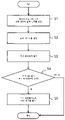
도 10은 상기 상태 진단 시스템에 의해 실시되는 상태 진단 방법의 일례를 나타내는 흐름도이며, 상기 제1 처리 모드 및 상기 제2 처리 모드가 조합되어 있다.Fig. 10 is a flowchart showing an example of a condition diagnosis method implemented by the condition diagnosis system, wherein the first processing mode and the second processing mode are combined.
이 진단 방법에 있어서, 상기 진단 처리부(39)는 우선 상기 제1 처리 모드를 실시한다(M11). 이 제1 처리 모드는 도 4에 나타내는 진단 처리의 S1∼S3에 상당하고, 데이터 수집 시간 T1에 대응한 제1 분석 데이터가 생성된다. 생성된 제1 분석 데이터는 제1 역치 데이터와 비교된다(M12). 비교 결과, 제1 처리 모드에서 얻어진 제1 분석 데이터가 제1 역치 데이터보다 큰 것이면, 상기 궤도 부재(1)의 구름 주행면(11) 또는 상기 이동 부재(2)의 부하 구름 주행면(23) 중 어느 것에 파손이 발생하였을 것이 우려되고, 이 경우에 상기 진단 처리부(39)는 상기 제1 처리 모드에 이어서 상기 제2 처리 모드를 실행한다(M21). 또한, 제1 처리 모드에서 얻어진 제1 분석 데이터가 제1 역치 데이터와 동등하거나 혹은 그보다 작은 것이면, 상기 궤도 부재(1)의 구름 주행면(11) 또는 상기 이동 부재(2)의 부하 구름 주행면(23) 중 어느 것에도 파손이 발생하지 않았다고 생각할 수 있어, 상기 진단 처리부(39)는 진단 방법을 종료한다.In this diagnostic method, the
상기 제2 처리 모드는 도 4에 나타내는 진단 처리의 S1∼S3에 상당하고, 데이터 수집 시간 T2에 대응한 제2 분석 데이터가 생성된다. 생성된 제2 분석 데이터는 제2 역치 데이터와 비교된다(M22). 비교 결과, 제2 처리 모드에서 얻어진 제2 분석 데이터가 제2 역치 데이터보다 작은 것이면, 상기 궤도 부재(1)의 구름 주행면(11)의 일부에 플레이킹 등의 파손이 발생하였다고 생각할 수 있어, 상기 진단 처리부(39)는, 상기 유저 인터페이스(40)에 대해 상기 궤도 부재(1)의 이상을 알리는 신호를 발보한다(M23).The second processing mode corresponds to S1 to S3 of the diagnostic processing shown in FIG. 4, and second analysis data corresponding to the data collection time T2 is generated. The generated second analysis data is compared with the second threshold data (M22). As a result of the comparison, if the second analysis data obtained in the second processing mode is smaller than the second threshold data, it can be considered that damage such as flaking has occurred in a part of the rolling
이에 비해, 제2 처리 모드에서 얻어진 제2 분석 데이터가 제2 역치 데이터보다 큰 것이면, 상기 이동 부재(2)의 부하 구름 주행면(23)에 플레이킹 등의 파손이 발생하였다고 생각할 수 있어, 상기 진단 처리부(39)는 상기 유저 인터페이스(40)에 대해 상기 이동 부재(2)의 파손을 알리는 이상 신호를 발보한다(M24). 또한, 상기 궤도 부재(1)의 구름 주행면(11)에 대해 플레이킹 등의 파손이 광범위에 걸쳐 발생하는 경우도, 상기 진동 센서의 출력 신호는 도 9의 신호 파형 (b)와 같이 되어, 제2 처리 모드에서 얻어진 제2 분석 데이터가 제2 역치 데이터보다 커진다. 그러나 상기 궤도 부재(1)의 구름 주행면(11)의 파손의 주된 요인은 구름 이동체(6)의 구름에 의한 금속 피로이며, 파손이 상기 구름 주행면(11)의 전역에 한 번에 발생한다고는 생각하기 어렵다. 따라서, 구름 안내 장치의 누적 사용 시간이 적은 것이면, 상기 제2 분석 데이터가 상기 제2 역치 데이터보다 커지는 원인은, 상기 이동 부재(2)의 부하 구름 주행면(23)의 파손이라고 판단할 수 있다.In contrast, if the second analysis data obtained in the second processing mode is greater than the second threshold data, it can be considered that damage such as flaking has occurred in the
상기 진단 처리부(39)는 상기 유저 인터페이스(40)에 대해 이상을 알리는 신호를 발보하는 것 이외에, 상기 구름 안내 장치를 사용하는 공작 기계 등의 기기에 대해 상기 판단 결과를 출력하도록 해도 된다. 또한, 상기 진단 처리부(39)는, 상기 제1 처리 모드에서 제1 분석 데이터를 상기 제1 역치 데이터와 비교하고, 당해 제1 분석 데이터가 제1 역치 데이터와 동등하거나 혹은 그보다 작다고 판단한 경우에는, 구름 안내 장치의 주행이 정상인 것을 나타내는 판정 신호를 상기 유저 인터페이스(40)에 대해 출력하도록 구성해도 된다.In addition to issuing a signal notifying an abnormality to the
전술한 바와 같이, 구름 안내 장치에 불량이 발생하였을 때에는, 당해 구름 안내 장치가 정상적으로 동작하고 있는 경우와는 상이한 진동이 상기 이동 부재(2)에 발생한다. 그러나 구름 안내 장치에 불량이 발생한 경우에는, 상기 이동 부재(2)의 진동의 변화 이외에도, 상기 궤도 부재(1)를 따라 상기 이동 부재(2)를 이동시킬 때의 주행음의 변화나 추력의 변화, 혹은 상기 궤도 부재(1) 상에 있어서의 상기 이동 부재(2)의 변위 등, 당해 구름 안내 장치가 정상적으로 동작하고 있는 경우와는 상이한 다양한 물리량의 변화가 발생한다. 따라서, 그러한 물리량의 변화를 각종 센서에 의해 검출하고, 그 검출 신호를 이용하여 본 발명의 상태 진단을 실시하는 것도 가능하다.As described above, when a defect occurs in the rolling guide device, a vibration different from that in the case where the rolling guide device is operating normally occurs in the moving
예를 들어, 상기 궤도 부재(1)의 길이 방향과 직교하는 방향에 관한 상기 이동 부재(2)의 미소 변위를 검출하는 변위 센서, 상기 이동 부재(2)를 정속으로 이동시킬 때에 필요한 추력의 변화를 검출하는 로드셀, 상기 안내 시스템의 볼 나사 장치를 구동하는 모터에의 통전 전류를 검출하는 전류계, 상기 이동 부재(2)가 상기 궤도 부재(1)를 따라 이동할 때의 소리의 변화를 검출하는 마이크로폰 등, 상기 이동 부재(2)와 상기 궤도 부재가 상대적으로 이동하였을 때에 발생하는 물리량의 변화를 파악하는 것이 가능한 센서이면, 상기 진동 센서(35) 대신에 사용하는 것이 가능하다.For example, a displacement sensor that detects a minute displacement of the
이상 설명되어진 바와 같이, 본 발명의 구름 안내 장치의 상태 진단 시스템 및 상태 진단 방법에서는, 상기 궤도 부재(1)를 따라 이동하는 상기 이동 부재(2)의 진동을 센서로 검출하여, 당해 센서의 출력 신호로부터 구름 안내 장치에 무언가의 불량이 발생하였는지 여부를 판단하고 있다. 그 때, 상기 센서의 출력 신호를 도입하는 진단 제어부(39)는 데이터 수집 시간이 상이한 제1 처리 모드 및 제2 처리 모드를 갖고 있어, 이들 두 개의 처리 모드에서의 판단 결과를 조합함으로써, 구름 안내 장치의 불량 원인이 상기 궤도 부재(1) 또는 상기 이동 부재(2) 중 어느 것에 기인하는 것인지를 밝히는 것이 가능해진다.As described above, in the condition diagnosis system and condition diagnosis method of the rolling guide device of the present invention, the vibration of the moving
또한, 도면을 사용하여 설명한 실시 형태의 구름 안내 장치는, 상기 궤도 부재(1)가 고정부 상에 부설되는 타입의 것이었지만, 예를 들어 볼 스플라인 장치나 볼 나사 장치 등, 궤도 부재가 봉축상으로 형성되어 그 양단부만이 고정부에 지지되는 타입의 구름 안내 장치에 적용하는 것도 가능하다.In the rolling guide device of the embodiment described with reference to the drawings, the track member 1 is of a type laid on a fixed portion, but, for example, a ball spline device or a ball screw device, the track member is on a rod shaft. It is also possible to apply it to a rolling guide device of a type in which only both ends are supported by a fixing part.
Claims (9)
상기 이동 부재(2)가 상기 궤도 부재(1)를 따라 이동하고 있을 때의 물리량을 검출하는 센서(35)와,
상기 센서(35)의 출력 신호를 소정 시간만큼 도입하고, 도입된 복수의 순시값을 제곱 평균 제곱근 처리하여 대표값을 나타내는 분석 데이터를 생성함과 함께, 상기 분석 데이터를 역치 데이터와 비교하고, 당해 비교 결과에 따라서 상기 구름 안내 장치의 이상의 유무를 판정하여, 당해 판정 결과를 출력하는 진단 처리부(39)를 구비하고,
상기 진단 처리부는,
상기 무한 순환로(5) 내에서 전후하는 구름 이동체(6)가 상기 무부하 통로(51, 52)로부터 상기 부하 통로(50)로 진입하는 주기를 t로 한 경우, 데이터 수집 시간 T1을 T1=nt(n은 자연수)로 하고, 상기 데이터 수집 시간 T1만큼 상기 센서(35)의 출력 신호를 도입하여 제1 분석 데이터를 생성하고, 당해 제1 분석 데이터를 제1 역치 데이터와 비교하는 제1 처리 모드와,
상기 궤도 부재(1)에 대한 상기 이동 부재(2)의 이동 속도를 v, 상기 부하 통로의 길이를 L1로 한 경우, 데이터 수집 시간 T2는 T2>L1/v로 하고, 상기 데이터 수집 시간 T2만큼 상기 센서(35)의 출력 신호를 도입하여 제2 분석 데이터를 생성하고, 당해 제2 분석 데이터를 제2 역치 데이터와 비교하는 제2 처리 모드를 구비하고,
상기 제1 처리 모드에 의한 비교 결과와 상기 제2 처리 모드에 의한 비교 결과의 조합으로부터, 상기 구름 안내 장치의 이상의 유무가 상기 궤도 부재(1) 또는 상기 이동 부재(2) 중 어느 것에 기인하고 있는지를 판정하여, 당해 판정 결과를 출력하는
것을 특징으로 하는 구름 안내 장치의 상태 진단 시스템.A plurality of rolling bodies 6, a track member 1 having a rolling surface of the rolling body along the longitudinal direction, assembled to the track member through the rolling body, and a load passage of the rolling body ( 50) and a moving member 2 having an endless circulation path 5 of the rolling body composed of unloaded passages 51 and 52 connecting both ends of the load passage. A condition diagnosis system for a rolling guide device,
A sensor (35) for detecting a physical quantity when the moving member (2) is moving along the track member (1);
The output signal of the sensor 35 is introduced for a predetermined time, and a plurality of introduced instantaneous values are subjected to root mean square processing to generate analysis data representing a representative value, and the analysis data is compared with threshold data, A diagnosis processing unit (39) for determining whether or not there is an abnormality in the rolling guide device according to a comparison result and outputting the determination result,
The diagnostic processing unit,
When the period in which the rolling body 6 moves back and forth in the endless circulation path 5 enters the load passage 50 from the no-load passages 51 and 52 as t, the data collection time T1 is T1 = nt ( n is a natural number), a first processing mode in which first analysis data is generated by introducing an output signal of the sensor 35 for the data collection time T1 and the first analysis data is compared with first threshold data; and ,
When the moving speed of the moving member 2 relative to the track member 1 is v and the length of the load passage is L1, the data collection time T2 is T2 > L1/v, and the data collection time T2 is A second processing mode for generating second analysis data by introducing an output signal of the sensor 35 and comparing the second analysis data with second threshold data;
From the combination of the comparison result in the first processing mode and the comparison result in the second processing mode, whether or not the rolling guide device has an abnormality is caused by either the track member 1 or the moving member 2. and outputting the result of the judgment
The condition diagnosis system of the cloud guidance device, characterized in that.
상기 제1 처리 모드에 의한 상기 제1 분석 데이터와 상기 제1 역치 데이터의 비교 결과로부터 상기 구름 안내 장치에 이상 있음이라고 판단한 경우에만, 상기 제2 처리 모드에 의한 상기 제2 분석 데이터와 상기 제2 역치 데이터의 비교를 행하는 것을 특징으로 하는 구름 안내 장치의 상태 진단 시스템.According to claim 1,
The second analysis data according to the second processing mode and the second analysis data according to the second processing mode and the second analysis data according to the second processing mode only when it is determined that there is an abnormality in the rolling guidance device based on the comparison result between the first analysis data and the first threshold data according to the first processing mode. A condition diagnosis system for a rolling guidance device characterized by performing comparison of threshold data.
상기 궤도 부재(1)에 대한 상기 이동 부재(2)의 이동 속도를 검출하고, 이들 검출 결과에 기초하여 상기 주기 t를 파악하는 것을 특징으로 하는 구름 안내 장치의 상태 진단 시스템.According to claim 1,
A state diagnosis system for a rolling guide device, characterized in that the moving speed of the moving member (2) with respect to the track member (1) is detected, and the period t is grasped based on these detection results.
상기 이동 부재(2)가 상기 궤도 부재(1)를 따라 이동하고 있을 때에 발생하는 물리량의 변화를 센서(35)에 의해 소정 시간만큼 도입하고, 도입된 복수의 순시값을 제곱 평균 제곱근 처리하여 대표값을 나타내는 분석 데이터를 생성하고, 당해 분석 데이터를 역치 데이터와 비교하여 상기 구름 안내 장치의 이상의 유무를 판정하는 상태 진단 방법이며,
상기 무한 순환로(5) 내에서 전후하는 구름 이동체(6)가 상기 무부하 통로(51, 52)로부터 상기 부하 통로(50)로 진입하는 주기를 t로 한 경우, 데이터 수집 시간 T1을 T1=nt(n은 자연수)로 하고, 상기 데이터 수집 시간 T1만큼 상기 센서의 출력 신호를 도입하여 제1 분석 데이터를 생성하고, 당해 제1 분석 데이터와 제1 역치 데이터를 비교하는 제1 스텝과,
상기 제1 분석 데이터가 상기 제1 역치 데이터보다 큰 경우에, 상기 궤도 부재(1)에 대한 상기 이동 부재(2)의 이동 속도를 v, 상기 부하 통로(50)의 길이를 L1로 한 경우, 데이터 수집 시간 T2을 T2>L1/v로 하고, 상기 데이터 수집 시간 T2만큼 상기 센서의 출력 신호를 도입하여 제2 분석 데이터를 생성하고, 당해 제2 분석 데이터와 제2 역치 데이터를 비교하는 제2 스텝과, 상기 제2 분석 데이터가 상기 제2 역치 데이터 이하인 경우에는 상기 궤도 부재(1)의 이상을 나타내는 신호를 출력하는 제3 스텝을 구비한 것을 특징으로 하는 구름 안내 장치의 상태 진단 방법.A plurality of rolling bodies 6, a track member 1 having a rolling surface of the rolling body along the longitudinal direction, assembled to the track member through the rolling body, and a load passage of the rolling body ( 50) and an endless circulation path 5 of the rolling body comprising unloaded passages 51 and 52 connecting both ends of the load passage.
A change in the physical quantity that occurs when the moving member 2 is moving along the track member 1 is introduced for a predetermined time by the sensor 35, and a plurality of introduced instantaneous values are represented by root mean square root processing A state diagnosis method for generating analysis data representing a value and comparing the analysis data with threshold data to determine whether or not there is an abnormality in the rolling guide device;
When the period in which the rolling body 6 moves back and forth in the endless circulation path 5 enters the load passage 50 from the no-load passages 51 and 52 as t, the data collection time T1 is T1 = nt ( n is a natural number), a first step of generating first analysis data by introducing an output signal of the sensor for the data collection time T1, and comparing the first analysis data with first threshold data;
When the first analysis data is greater than the first threshold data, when the moving speed of the moving member 2 relative to the track member 1 is v and the length of the load passage 50 is L1, The second analysis data is generated by introducing the output signal of the sensor for the data collection time T2 when the data collection time T2 is set to T2>L1/v, and the second analysis data is compared with the second threshold data. and a third step of outputting a signal indicating an abnormality of the track member (1) when the second analysis data is equal to or less than the second threshold data.
상기 제2 분석 데이터가 상기 제2 역치 데이터보다 큰 경우에는 상기 이동 부재(2)의 이상을 나타내는 신호를 출력하는 것을 특징으로 하는 구름 안내 장치의 상태 진단 방법.According to claim 4,
and outputting a signal indicating an abnormality of the moving member (2) when the second analysis data is greater than the second threshold data.
Applications Claiming Priority (3)
| Application Number | Priority Date | Filing Date | Title |
|---|---|---|---|
| JP2017033921A JP6841558B2 (en) | 2017-02-24 | 2017-02-24 | Condition diagnosis system and condition diagnosis method of rolling guidance device |
| JPJP-P-2017-033921 | 2017-02-24 | ||
| PCT/JP2018/003607 WO2018155136A1 (en) | 2017-02-24 | 2018-02-02 | Status diagnosing system for rolling guide device, and status diagnosing method |
Publications (2)
| Publication Number | Publication Date |
|---|---|
| KR20190121333A KR20190121333A (en) | 2019-10-25 |
| KR102491553B1 true KR102491553B1 (en) | 2023-01-20 |
Family
ID=63254182
Family Applications (1)
| Application Number | Title | Priority Date | Filing Date |
|---|---|---|---|
| KR1020197027408A KR102491553B1 (en) | 2017-02-24 | 2018-02-02 | Condition diagnosis system and condition diagnosis method of cloud guidance device |
Country Status (7)
| Country | Link |
|---|---|
| US (1) | US20190361758A1 (en) |
| JP (1) | JP6841558B2 (en) |
| KR (1) | KR102491553B1 (en) |
| CN (1) | CN110214236B (en) |
| DE (1) | DE112018001008T5 (en) |
| TW (1) | TWI760442B (en) |
| WO (1) | WO2018155136A1 (en) |
Families Citing this family (7)
| Publication number | Priority date | Publication date | Assignee | Title |
|---|---|---|---|---|
| TWI668378B (en) * | 2018-04-23 | 2019-08-11 | 直得科技股份有限公司 | Miniature linear slide and its slide |
| KR102398307B1 (en) * | 2019-03-26 | 2022-05-16 | 도시바 미쓰비시덴키 산교시스템 가부시키가이샤 | Abnormality judgment support device |
| JP2020160680A (en) * | 2019-03-26 | 2020-10-01 | キヤノン株式会社 | Electronic apparatus, control method for controlling electronic apparatus, computer program and storage medium |
| JP7412158B2 (en) * | 2019-12-18 | 2024-01-12 | オークマ株式会社 | Machine tool feed axis diagnosis device and feed axis diagnosis method |
| CN111964909A (en) * | 2020-08-24 | 2020-11-20 | 山东大学 | Rolling bearing operation state detection method, fault diagnosis method and system |
| TWI752751B (en) | 2020-12-09 | 2022-01-11 | 上銀科技股份有限公司 | Device and method for detecting states of linear guideway |
| TW202332842A (en) * | 2021-12-27 | 2023-08-16 | 日商電裝股份有限公司 | Failure sign detection system for sliding mechanism protection member, failure sign detection method for sliding mechanism protection member, and failure sign detection program for sliding mechanism protection member |
Citations (1)
| Publication number | Priority date | Publication date | Assignee | Title |
|---|---|---|---|---|
| JP2005017128A (en) * | 2003-06-26 | 2005-01-20 | Nsk Ltd | Metod and apparatus for observing condition of machine equipment |
Family Cites Families (15)
| Publication number | Priority date | Publication date | Assignee | Title |
|---|---|---|---|---|
| JPS5554429A (en) * | 1978-10-17 | 1980-04-21 | Toshiba Corp | Bearing supervisory unit |
| JPH0616001B2 (en) * | 1987-10-02 | 1994-03-02 | 日本たばこ産業株式会社 | Non-destructive inspection method and device for rolling bearing |
| JPH05281094A (en) * | 1992-03-31 | 1993-10-29 | Nkk Corp | Inspection method of directly moving type guide provided with circulating type rolling guide and its apparatus |
| JP2004003573A (en) * | 2002-04-26 | 2004-01-08 | Nsk Ltd | Rolling device sensor |
| JP3874110B2 (en) | 2002-08-30 | 2007-01-31 | 日本精工株式会社 | Abnormality diagnosis system |
| JP4430316B2 (en) * | 2003-02-28 | 2010-03-10 | Thk株式会社 | Status detection apparatus, status detection method, status detection program, and information recording medium |
| US7546211B2 (en) * | 2004-08-31 | 2009-06-09 | Thk Co., Ltd. | Condition detection apparatus, condition detection method, condition detection program, information recording medium therefor, and condition display apparatus, condition display method, condition display program, information recording medium therefor |
| JP2008303954A (en) * | 2007-06-06 | 2008-12-18 | Nsk Ltd | Linear motion device |
| JP2009092183A (en) * | 2007-10-11 | 2009-04-30 | Nsk Ltd | Linearly moving device and its abnormality determining device |
| JP2009257806A (en) * | 2008-04-14 | 2009-11-05 | Nsk Ltd | Method and apparatus for determining abnormality of rolling linear motion device |
| JP6051606B2 (en) * | 2012-06-14 | 2016-12-27 | 日本精工株式会社 | Abnormality detection device and abnormality detection method for ball screw device |
| CN104314997B (en) * | 2014-08-19 | 2019-01-15 | 中广核工程有限公司 | Bearing shell slant detection method and automatic inclination correction method |
| JP6605865B2 (en) * | 2015-07-22 | 2019-11-13 | Ntn株式会社 | Rolling bearing state monitoring device and rolling bearing state monitoring method |
| JP6714806B2 (en) * | 2015-08-06 | 2020-07-01 | 日本精工株式会社 | Status monitoring device and status monitoring method |
| CN106015328B (en) * | 2016-06-28 | 2018-10-26 | 嘉兴海菱达精密传动科技有限公司 | A kind of linear rolling guide |
-
2017
- 2017-02-24 JP JP2017033921A patent/JP6841558B2/en active Active
-
2018
- 2018-02-02 CN CN201880008285.XA patent/CN110214236B/en active Active
- 2018-02-02 US US16/479,425 patent/US20190361758A1/en not_active Abandoned
- 2018-02-02 WO PCT/JP2018/003607 patent/WO2018155136A1/en active Application Filing
- 2018-02-02 DE DE112018001008.2T patent/DE112018001008T5/en active Pending
- 2018-02-02 KR KR1020197027408A patent/KR102491553B1/en active IP Right Grant
- 2018-02-22 TW TW107105917A patent/TWI760442B/en active
Patent Citations (1)
| Publication number | Priority date | Publication date | Assignee | Title |
|---|---|---|---|---|
| JP2005017128A (en) * | 2003-06-26 | 2005-01-20 | Nsk Ltd | Metod and apparatus for observing condition of machine equipment |
Also Published As
| Publication number | Publication date |
|---|---|
| KR20190121333A (en) | 2019-10-25 |
| JP2018138817A (en) | 2018-09-06 |
| CN110214236A (en) | 2019-09-06 |
| WO2018155136A1 (en) | 2018-08-30 |
| DE112018001008T5 (en) | 2019-11-07 |
| US20190361758A1 (en) | 2019-11-28 |
| CN110214236B (en) | 2020-11-03 |
| TW201843549A (en) | 2018-12-16 |
| JP6841558B2 (en) | 2021-03-10 |
| TWI760442B (en) | 2022-04-11 |
Similar Documents
| Publication | Publication Date | Title |
|---|---|---|
| KR102491553B1 (en) | Condition diagnosis system and condition diagnosis method of cloud guidance device | |
| US10712236B2 (en) | Condition diagnosing system for rolling guide device | |
| US7555953B2 (en) | Condition-detecting device, method, and program, and information-recording medium | |
| US10968956B2 (en) | Method for diagnosing state of rolling guide device | |
| JP2018138817A5 (en) | ||
| KR20210080353A (en) | A method for detecting a drop in preload of a ball screw and a direct-acting drive device | |
| JP2009198398A (en) | Operation state inspection method and device of rolling linear motion device | |
| JP2008304244A (en) | Inspection method of linear rolling guide device, and linear rolling guide device | |
| Pichler et al. | Detecting wear in a ball screw using a data-driven approach | |
| Sghir et al. | Vibratory monitoring of a spalling bearing defect in variable speed regime | |
| WO2019058965A1 (en) | Method for diagnosing state of rolling guide device | |
| JP6396943B2 (en) | Failure diagnosis apparatus and method by non-contact vibration measurement | |
| JP2005147848A (en) | Abnormality portent method and abnormality portent system | |
| US11585718B2 (en) | Method and device for imbalance detection | |
| Patidar et al. | Study of detection of defects in rolling element bearings using vibration and acoustic measurement methods-A Review | |
| JP2021085695A (en) | Linear guide condition monitoring device and condition monitoring method | |
| JP2021042787A (en) | State detection method of rolling guide device | |
| JP2021085693A (en) | Ball screw condition monitoring device and condition monitoring method |
Legal Events
| Date | Code | Title | Description |
|---|---|---|---|
| A201 | Request for examination | ||
| E902 | Notification of reason for refusal | ||
| E701 | Decision to grant or registration of patent right | ||
| GRNT | Written decision to grant |