KR102459033B1 - A clamping device for fixing overhead distribution lines for stable support of overhead distribution lines - Google Patents
A clamping device for fixing overhead distribution lines for stable support of overhead distribution lines Download PDFInfo
- Publication number
- KR102459033B1 KR102459033B1 KR1020220012953A KR20220012953A KR102459033B1 KR 102459033 B1 KR102459033 B1 KR 102459033B1 KR 1020220012953 A KR1020220012953 A KR 1020220012953A KR 20220012953 A KR20220012953 A KR 20220012953A KR 102459033 B1 KR102459033 B1 KR 102459033B1
- Authority
- KR
- South Korea
- Prior art keywords
- overhead distribution
- ground
- grounding
- fixing
- wire
- Prior art date
Links
Images


Classifications
-
- H—ELECTRICITY
- H02—GENERATION; CONVERSION OR DISTRIBUTION OF ELECTRIC POWER
- H02G—INSTALLATION OF ELECTRIC CABLES OR LINES, OR OF COMBINED OPTICAL AND ELECTRIC CABLES OR LINES
- H02G7/00—Overhead installations of electric lines or cables
- H02G7/05—Suspension arrangements or devices for electric cables or lines
- H02G7/053—Suspension clamps and clips for electric overhead lines not suspended to a supporting wire
-
- G—PHYSICS
- G01—MEASURING; TESTING
- G01R—MEASURING ELECTRIC VARIABLES; MEASURING MAGNETIC VARIABLES
- G01R19/00—Arrangements for measuring currents or voltages or for indicating presence or sign thereof
- G01R19/145—Indicating the presence of current or voltage
- G01R19/15—Indicating the presence of current
-
- H—ELECTRICITY
- H02—GENERATION; CONVERSION OR DISTRIBUTION OF ELECTRIC POWER
- H02G—INSTALLATION OF ELECTRIC CABLES OR LINES, OR OF COMBINED OPTICAL AND ELECTRIC CABLES OR LINES
- H02G1/00—Methods or apparatus specially adapted for installing, maintaining, repairing or dismantling electric cables or lines
- H02G1/02—Methods or apparatus specially adapted for installing, maintaining, repairing or dismantling electric cables or lines for overhead lines or cables
Abstract
Description
본 발명은 가공배전라인의 안정적 지지가 가능한 가공배전선 고정 클램프 장치에 관한 것이다.The present invention relates to an overhead distribution line fixing clamp device capable of stably supporting the overhead distribution line.
일반적으로 발전소에서 생산된 전력은 송전탑 등의 송전선로를 통해 고압의 전력으로 각 변전소로 송전된 다음, 변전소에서는 여러 단계의 변압과정을 거쳐 각 가정 또는 건물 등의 수용가에서 사용할 수 있도록 케이블을 이용하여 각 지역으로 공급하게 되는 배전과정을 거치게 된다.In general, the power produced in the power plant is transmitted to each substation as high-voltage power through a transmission line such as a power transmission tower, and then the substation goes through several stages of transformation process using a cable so that it can be used by consumers in each house or building. It goes through a distribution process that is supplied to each region.
이때, 일반 수용가로의 전력공급은 일정간격으로 설치되는 전신주를 통해 공급하고, 각 전신주에서의 연결은 점퍼선을 이용하여 연결하게 된다.At this time, the power supply to the general consumer is supplied through the poles installed at regular intervals, and the connection at each pole is connected using a jumper wire.
즉, 전신주에 연결하고자 하는 배전선을 전신주 상단 양측에 횡으로 설치되는 완금의 양측에서 애자를 통해 결합하고, 애자 사이를 점퍼선으로 연결하되, 연결되는 점퍼선은 완금의 상단 또는 하단에 설치되는 애자를 통해 고정될 수 있도록 시공하여 사용하였다.That is, the distribution line to be connected to the utility pole is coupled through insulators from both sides of the wangeum installed horizontally on both sides of the top of the pole, and the insulators are connected with a jumper wire, but the connected jumper wire is an insulator installed at the top or bottom of the wangeum It was constructed so that it could be fixed through the
그런데 종래에는 전력연결을 차단하고자 할 경우 전원공급을 차단한다거나 배전선과 연결된 점퍼선을 분리하는 방식을 통해 전원연결을 차단해야 한다는 점에서 작업시간이 오래 걸리고, 작업이 상당히 번거롭고 불편한 문제가 있었다.However, in the prior art, when the power connection is to be cut off, the power supply must be cut off or the power connection must be cut off through a method of disconnecting the jumper wire connected to the distribution line.
본 발명은 점퍼선을 쉽고 간편하게 연결 및 해제할 수 있어 작업의 편의성이 향상되고, 점퍼선의 활선상태를 시각적으로 확인 가능해 감전의 위험으로부터 작업자를 안전하게 보호해 줄 수 있는 가공배전라인의 안정적 지지가 가능한 가공배전선 고정 클램프 장치를 제공하려는데 그 목적이 있다.The present invention can easily and conveniently connect and disconnect the jumper wire, improving the convenience of work, and visually checking the state of the live wire of the jumper wire so that it is possible to stably support the overhead distribution line that can safely protect the operator from the risk of electric shock. An object of the present invention is to provide a clamping device for fixing overhead distribution lines.
상기 목적을 달성하기 위한 본 발명은, The present invention for achieving the above object,
전신주의 상단부에 나란하게 설치되며, 서로 마주보는 면에 내부와 연통되는 결합부가 형성된 완철;Wancheol installed side by side on the upper end of the telephone pole, and formed with a coupling portion communicating with the inside on the opposite side;
체결수단을 매개로 완철에 설치되며 쇄클아이를 구비하는 아이쇄클과, 쇄클아이에 쇄클코터핀을 매개로 상호 연결되는 현수애자와, 현수애자의 단부에 애자코터핀을 매개로 상호연결되며 가공배전선 및 가공배전선을 전기적으로 상호 연결하는 점퍼선이 각각 결합 고정되는 픽스금구로 구성된 전선고정유닛;An eye shackle installed on the armrest via a fastening means and having a shackle eye, a suspension insulator interconnected to the shackle eye via a shackle cotter pin, and an overhead distribution line interconnected through an insulator cotter pin at the end of the suspension insulator and a wire fixing unit comprising a fixing bracket to which jumper wires electrically interconnecting overhead distribution lines are coupled and fixed, respectively;
완철의 결합부에 양단부가 삽탈가능하게 끼워져 완철과 직교를 이루는 방향으로 배치되는 절연재질의 지지대와,A support made of an insulating material, which is disposed in a direction perpendicular to the arm with both ends being detachably inserted into the coupling part of the arm;
지지대로부터 하방으로 연장된 제1바디, 제1바디를 전후방으로 관통하는 타원형상의 가이드부, 가이드부를 기준으로 상부에 배치되며 내부가 함몰된 제1스프링수용부, 가이드부를 기준으로 하부에 배치되며 내부가 함몰된 제1접지수용부, 제1스프링수용부의 중심으로부터 전방으로 돌출된 축봉, 축봉으로부터 이격배치된 제1돌부로 이루어진 절연재질의 고정대와,A first body extending downward from the support, an oval-shaped guide part penetrating the first body forward and backward, a first spring receiving part with a recessed inside and disposed on the upper part based on the guide part, and disposed on the lower part based on the guide part, inside A fixing base made of an insulating material consisting of a recessed first grounding receiving part, a shaft protruding forward from the center of the first spring receiving part, and a first protrusion spaced apart from the shaft;
제1바디의 전면에 회전가능하게 맞대어지는 제2바디, 제2바디를 전후방으로 관통하는 아크홀과, 아크홀의 말단으로부터 상방으로 연장된 걸림홀로 이루어진 잠금쇠결합부, 제1스프링수용부와 서로 마주보게 잠금쇠결합부를 기준으로 상부에 배치되며 내부가 함몰된 제2스프링수용부, 제1접지수용부와 서로 마주보게 잠금쇠결합부를 기준으로 하부에 배치되며 내부가 함몰되되, 내면에는 서로 대향되게 돌출된 제1걸림턱이 일체로 형성된 제2접지수용부, 축봉이 회전가능하게 끼워질 수 있도록 제2스프링수용부의 중심을 관통하는 봉결합부, 봉결합부로부터 이격배치된 제2돌부로 이루어진 절연재질의 가동대와,The second body rotatably abutted on the front surface of the first body, an arc hole penetrating the second body in the front and rear, and a stopper coupling part comprising a locking hole extending upward from the end of the arc hole, the first spring receiving part and facing each other It is disposed on the upper part based on the lock clamp coupling part and is disposed on the lower part based on the lock clamp coupling part to face each other with the second spring receiving part and the first ground receiving part which are recessed inside. An insulating material consisting of a second grounding receiving portion integrally formed with the first locking protrusion, a rod coupling portion penetrating the center of the second spring receiving portion so that the shaft can be rotatably fitted, and a second protrusion spaced apart from the rod coupling portion of the movable table,
가이드부에 승강가능하게 결합되며 잠금쇠결합부에 삽탈가능하게 끼워져 가동대의 회동을 제한하는 잠금쇠와,a stopper that is movably coupled to the guide part and is detachably inserted into the stopper coupling part to limit the rotation of the movable table;
제1바디에 일단부가 고정되고 잠금쇠에 타단부가 고정되어 잠금쇠를 탄발지지하는 코일스프링과,A coil spring having one end fixed to the first body and the other end fixed to the locking member to elastically support the locking member;
압축된 상태로 축봉에 끼워져 일단부가 제1돌부에 걸림되고, 타단부가 제2돌부에 걸림되어 탄성복원력을 매개로 가동대를 축봉을 중심으로 회전시키는 토션스프링과,A torsion spring that is inserted into the shaft in a compressed state, one end is caught on the first protrusion, and the other end is caught on the second protrusion to rotate the movable bar around the shaft through the elastic restoring force;
외주면에 나사탭이 형성된 제1연결부를 갖추고서 제1접지수용부에 실장되는 전도성재질의 오목접지와,A concave grounding of a conductive material that is equipped with a first connection part having a screw tab formed on the outer circumferential surface and mounted on the first grounding receiving part;
제2접지수용부에 이동가능하게 수용되는 접지본체와, 접지본체의 양단으로부터 연장되어 제1걸림턱에 걸림되는 제2걸림턱과, 접지본체로부터 연장되어 제2접지수용부에 수용되며 외주면에 나사탭이 형성된 제2연결부와, 제2연결부를 기준으로 상호 대향되게 배치되되, 일단이 접지본체에 연결되고 타단이 제2접지수용부에 맞대어져 접지본체를 오목접지를 향해 탄발지지하는 판스프링으로 이루어진 전도성재질의 볼록접지와,A grounding body movably accommodated in the second grounding receiving unit, a second stopping protruding extending from both ends of the grounding body to be caught by the first stopping protruding, extending from the grounding body to be accommodated in the second grounding receiving unit and on the outer circumferential surface A leaf spring that is arranged to face each other with respect to the second connection part having a screw tab and the second connection part, and has one end connected to the grounding body and the other end abutting the second grounding receiving part to elastically support the grounding body toward the concave ground A convex ground made of a conductive material consisting of
오목접지의 제1연결부에 일단부가 착탈가능하게 전기적으로 연결되고, 고정대의 후방으로 타단부가 노출되어 점퍼선이 착탈가능하게 전기적으로 연결되는 제1전선단자부와,A first wire terminal part detachably electrically connected to the first connection part of the concave ground, and the other end is exposed to the rear of the fixing base so that the jumper wire is detachably electrically connected;
볼록접지의 제2연결부에 일단부가 착탈가능하게 전기적으로 연결되고, 가동대의 전방으로 타단부가 노출되어 점퍼선이 착탈가능하게 전기적으로 연결되는 제2전선단자부로 구성된 스위칭유닛;a switching unit configured with a second wire terminal part detachably electrically connected to a second connection part of the convex ground, the other end being exposed to the front of the movable table, to which a jumper wire is detachably electrically connected;
제1전선단자부를 따라 흐르는 전류를 감지하는 제1전류감지센서;a first current sensing sensor for sensing a current flowing along the first wire terminal;
제2전선단자부를 따라 흐르는 전류를 감지하는 제2전류감지센서;a second current sensing sensor for sensing a current flowing along the second wire terminal;
제1전류감지센서에 의해 동작제어되는 제1경광부;a first light unit operated by a first current sensing sensor;
제2전류감지센서에 의해 동작제어되는 제2경광부;를 포함하는 것을 특징으로 한다.It characterized in that it comprises;
본 발명은 점퍼선을 쉽고 간편하게 연결 및 해제할 수 있어 작업의 편의성이 향상되고, 점퍼선의 활선상태를 시각적으로 확인 가능해 감전의 위험으로부터 작업자를 안전하게 보호해 줄 수 있는 이점이 있다.The present invention has the advantage of being able to easily and conveniently connect and disconnect the jumper wire, thereby improving the convenience of work, and visually checking the live wire state of the jumper wire, thereby safely protecting the operator from the risk of electric shock.
도 1은 본 발명에 따른 가공배전선 고정 클램프 장치의 사시도.
도 2는 본 발명에 따른 가공배전선 고정 클램프 장치의 정면도.
도 3은 본 발명에 따른 가공배전선 고정 클램프 장치의 배면도.
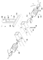
도 4는 본 발명에 따른 가공배전선 고정 클램프 장치의 분해사시도.
도 5는 본 발명에 따른 가공배전선 고정 클램프 장치에서 스위칭유닛을 따로 발췌하여 보인 분해사시도.
도 6은 도 4의 A - A 단면도.
도 7a 내지 도 7d는 본 발명에 따른 가공배전선 고정 클램프 장치의 사용상태를 설명하기 위한 도면.1 is a perspective view of an overhead distribution line fixing clamp device according to the present invention.
Figure 2 is a front view of the overhead distribution line fixing clamp device according to the present invention.
3 is a rear view of the overhead distribution line fixing clamp device according to the present invention.
4 is an exploded perspective view of the overhead distribution line fixing clamp device according to the present invention.
5 is an exploded perspective view showing the switching unit separately extracted from the overhead distribution line fixing clamp device according to the present invention.
6 is a cross-sectional view taken along line A - A of FIG. 4 .
7a to 7d are views for explaining the use state of the overhead distribution line fixing clamp device according to the present invention.
이하, 첨부된 도면에 의거하여 상세하게 설명한다.Hereinafter, it will be described in detail based on the accompanying drawings.
도 1은 본 발명에 따른 가공배전선 고정 클램프 장치의 사시도이고, 도 2는 본 발명에 따른 가공배전선 고정 클램프 장치의 정면도이며, 도 3은 본 발명에 따른 가공배전선 고정 클램프 장치의 배면도이며, 도 4는 본 발명에 따른 가공배전선 고정 클램프 장치의 분해사시도이며, 도 5는 본 발명에 따른 가공배전선 고정 클램프 장치에서 스위칭유닛을 따로 발췌하여 보인 분해사시도이며, 도 6은 도 4의 A - A 단면도이다.1 is a perspective view of an overhead distribution line fixing clamp device according to the present invention, FIG. 2 is a front view of the overhead distribution line fixing clamping device according to the present invention, and FIG. 3 is a rear view of the overhead distribution line fixing clamping device according to the present invention, FIG. 4 is an exploded perspective view of the overhead distribution line fixing clamp device according to the present invention, FIG. 5 is an exploded perspective view showing the switching unit separately extracted from the overhead distribution line fixing clamp device according to the present invention, and FIG. 6 is a cross-sectional view A-A of FIG. to be.
도 1 내지 도 4를 참조하면, 본 발명에 따른 가공배전선 고정 클램프 장치는, 완철(100)과 전선고정유닛(200), 스위칭유닛(300), 제1·2전류감지센서(400,400') 및 제1·2경광부(500,500')로 구성된 것으로서, 이에 의하면 점퍼선(J)을 쉽고 간편하게 연결 및 해제할 수 있어 작업의 편의성이 향상되고, 점퍼선(J)의 활선상태를 시각적으로 확인 가능해 감전의 위험으로부터 작업자를 안전하게 보호해 줄 수 있는 기술적인 특징이 있다.1 to 4, the overhead distribution line fixing clamp device according to the present invention, the
도 1 내지 도 3을 참조하면, 상기 완철(100)은 입설된 전신주(1)의 길이방향에 대해서 직교하도록 전신주(1)의 상단부에 나란하게 설치된다.1 to 3, the arm-
상기 완철(100)은 내부가 길이방향으로 관통된 사각관으로, 서로 마주보는 면의 일단부에는 내부와 상호 연통되는 결합부(110)가 일체로 형성되며, 이 결합부(110)에 스위칭유닛(300)을 구성하는 지지대(310)의 양단부가 삽탈가능하게 끼워져 완철(100)에 의해 지지된다.The
도 1 내지 도 4를 참조하면, 상기 전선고정유닛(200)은 아이쇄클(210)과 현수애자(220) 및 픽스금구(230)로 구성된 것으로서, 본 실시 예의 경우 완철(100)과 가공배전선(L) 사이에 설치되어 완철(100)과 가공배전선(L)이 전기적으로 접촉되지 않게 절연하고, 가공배전선(L) 및 가공배전선(L)을 전기적으로 상호 연결하는 점퍼선(J)을 고정하는 역할을 한다.1 to 4, the
상기 전선고정유닛(200)의 경우 해당 분야에서 널리 공지된 기술이므로 이하에서는 개략적으로 설명하고 넘어가기로 한다.In the case of the
상기 아이쇄클(210)은 대략‘C’자 형상을 갖는 부재로, 완철(100)에 체결수단(BN)을 매개로 회동가능하게 설치되며, 일측에는 쇄클아이(211)가 이동가능하게 설치된다. The
상기 현수애자(220)는 쇄클아이(211)에 쇄클코터핀(221)을 매개로 상호 연결되며, 쇄클코터핀(221)의 일단에는 분할핀이 관통되게 끼워져 쇄클코터핀(221)의 이탈을 단속한다. The
상기 픽스금구(230)는 가공배전선(L)이 결합고정되는 것으로, 현수애자(220)의 단부에 애자코터핀(231)을 매개로 상호 연결되며, 애자코터핀(231)의 일단에는 분할핀이 관통되게 끼워져 애자코터핀(231)의 이탈을 단속한다.The
도 1 내지 도 6을 참조하면, 상기 스위칭유닛(300)은 지지대(310)와 고정대(320), 가동대(330), 잠금쇠(340), 코일스프링(350), 토션스프링(360), 오목접지(370), 볼록접지(380) 및 제1·2전선단자부(390,390')로 구성된 것으로서, 본 실시 예의 경우 완철(100)에 착탈가능하게 설치되어 점퍼선(L)을 고정하면서 점퍼선(L)을 전기적으로 상호 연결 및 해제하는 역할을 한다.1 to 6 , the
상기 지지대(310)는 양단부가 각각 완철(100)의 결합부(110)에 삽탈가능하게 끼워져 완철(100)에 의해 지지되는 사각형상의 바이다.The
이러한 지지대(310)의 하면에는 완철(100) 사이에 배치되는 고정대(320)가 일체로 형성된다.On the lower surface of the
상기 고정대(320)는 제1바디(321)와 가이드부(322), 제1스프링수용부(323), 제1접지수용부(324), 축봉(325) 및 제1돌부(326)로 구성된다.The
상기 제1바디(321)는 직육체형상의 절연부재이다. The
상기 가이드부(322)는 제1바디(321)의 길이방향으로 형성된 장공이며, 잠금쇠(340)가 승강가능하게 설치된다.The
상기 가이드부(322)를 기준으로 상측과 하측에는 제1스프링수용부(323)와 제1접지수용부(324)가 각각 형성되는데, 여기서 제1스프링수용부(323)와 제1접지수용부(324)는 내부가 소정의 깊이로 함몰된 홈으로, 제1스프링수용부(323)에는 토션스프링(360)의 일부가 수용되고, 제1접지수용부(324)에는 오목접지(370)가 수용된다.A first
상기 제1스프링수용부(323)의 중앙에는 전방으로 돌출된 축봉(325)이 일체로 형성되고, 축봉(325)으로부터 이격된 위치에는 전방으로 돌출된 제1돌부(326)가 일체로 형성되어 토션스프링(360)의 일측을 지지한다.A
상기 가동대(330)는 제2바디(331)와 잠금쇠결합부(332), 제2스프링수용부(333), 제2접지수용부(334), 봉결합부(335) 및 제2돌부(336)로 구성된 것으로서, 본 실시 예의 경우 고정대(320)의 축봉(325)에 봉결합부(335)를 매개로 회동가능하게 설치된다.The movable table 330 includes a
상기 제2바디(331)는 직육면체형상의 절연부재이다.The
상기 잠금쇠결합부(332)는 아크홀(332a)과 걸림홀(332b)로 구성된다.The lock
상기 아크홀(332a)은 제2바디(331)의 길이방향에 대해서 교차되도록 횡 방향으로 형성되어 잠금쇠(340)의 이동을 가이드하는 역할을 한다.The arc hole (332a) is formed in the transverse direction to cross the longitudinal direction of the second body (331) serves to guide the movement of the stopper (340).
이러한 아크홀(332a)의 말단에는 상방으로 연장되어 아크홀(332a)을 따라 이동된 잠금쇠(340)가 걸림되는 걸림홀(332b)이 일체로 형성된다.At the distal end of the
상기 잠금쇠결합부(332)를 기준으로 상측과 하측에는 제2스프링수용부(333)와 제2접지수용부(334)가 각각 형성되는데, 여기서 제2스프링수용부(333)와 제2접지수용부(334)는 내부가 소정의 깊이로 함몰된 홈으로, 제2스프링수용부(333)에는 토션스프링(360)의 나머지 일부가 수용되고, 제2접지수용부(334)에는 볼록접지(380)가 수용된다.A second
상기 제2스프링수용부(333)의 중앙에는 축봉(325)이 회전가능하게 끼워지는 봉결합부(335)가 일체로 형성되고, 봉결합부(335)로부터 이격된 위치에는 후방으로 돌출된 제2돌부(336)가 일체로 형성되어 토션스프링(360)의 타측을 지지한다.At the center of the second
상기 제2접지수용부(334)에는 내면으로부터 서로 마주보게 돌출된 제1걸림턱(334a)이 일체로 형성되며, 여기서 제1걸림턱(334a)은 볼록접지(380)의 제2걸림턱(382)에 과도한 이동을 제한하여 제2접지수용부(334)로부터 볼록접지(380)가 이탈되는 것을 막아주는 역할을 한다.The second
상기 잠금쇠(340)는 환형의 봉으로, 본 실시 예의 경우 가이드부(322)에 승강가능하게 끼워져 가동대(330)의 회동을 단속하는 역할을 한다.The locking
상기 코일스프링(350)은 일단부가 고정대(320)의 제1바디(321)에 고정되고, 타단부가 잠금쇠(340)에 고정되어 잠금쇠(340)를 탄성복원력을 매개로 상방으로 잡아당기는 역할을 하며, 이에 따라 잠금쇠(340)는 아크홀(332a)을 따라 이동하는 과정에 걸림홀(332b)에 자연스럽게 삽입되면서 걸림되는 것이다.The
상기 토션스프링(360)은 축봉(325)에 끼워져 제1·2스프링수용부(232,333)에 수용되며, 일측이 제1돌부(326)에 의해 지지되고, 타측이 제2돌부(336)에 의해 지지되게 설치되어 탄성복원력을 매개로 가동대(330)를 회동시켜주는 역할을 한다.The
일 예로, 상기 고정대(320)와 가동대(330)를 동일 위치에 배치하게 되면, 토션스프링(360)은 압축되지만, 고정대(320)의 축봉(325)을 중심으로 가동대(330)를 회전시켜 주게 되면, 토션스프링(360)은 복원력에 의해 압축상태가 해제된다.As an example, when the fixing table 320 and the movable table 330 are disposed at the same position, the
상기 오목접지(370)는 전면이 오목하게 함몰된 전도성재질의 금속부재로, 제1접지수용부(324)에 수용된다. 이러한 오목접지(370)의 후면에는 후방으로 돌출된 제1연결부(371)가 일체로 형성되며, 제1연결부(371)는 외주면에 나사탭이 형성된 단봉이다.The
상기 볼록접지(380)는 접지본체(381)와 제2걸림턱(382), 제2연결부(383) 및 판스프링(384)로 구성된 전도성재질의 금속부재로, 본 실시 예의 경우 제2접지수용부(334)에 탄발가능하게 수용되어 오목접지(370)에 맞대어져 전기적으로 연결된다.The
상기 접지본체(381)의 후면은 오목접지(370)의 전면에 대응되는 볼록한 형태를 하고 있다. 또한, 접지본체(381)의 양측면에는 제2걸림턱(382)이 일체로 형성되며, 여기서 제2걸림턱(382)은 제1걸림턱(334a)에 의해 이동이 제한되어 제2접지수용부(334)로부터 볼록접지(380)가 이탈되는 것을 방지할 수 있도록 하였다. 그리고 접지본체(381)의 전면에는 전방으로 돌출된 제2연결부(383)가 일체로 형성되며, 제2연결부(383)는 외주면에 나사탭이 형성된 단봉이다. 마지막으로 접지본체(381)의 전면에는 제2연결부(383)를 기준으로 상호 대향되게 판스프링(384)이 형성되며, 여기서 판스프링(384)은 제2접지수용부(334)에 탄발가능하게 수용되며, 접지본체(381)를 오목접지(370)를 향해 밀어 접점이 보다 확실하게 유지될 수 있도록 하는 역할을 한다.The rear surface of the
상기 제1전선단자부(390)는 일단부가 고정대(320)를 관통해 제1연결부(371)와 전기적으로 연결되고, 타단부는 고정대(320)의 밖으로 노출되게 배치되어 점퍼선(J)과 전기적으로 연결된다. 이러한 제1전선단자부(390)의 내부는 도체이고, 외부는 절연체로 감싸져 있다.The first
상기 제2전선단자부(390')는 일단부가 가동대(330)를 관통해 제2연결부(383)와 전기적으로 연결되고, 타단부는 가동대(330)의 밖으로 노출되게 배치되어 점퍼선(J)과 전기적으로 연결된다. 이러한 제2전선단자부(390')의 내부는 도체이고, 외부는 절연체로 감싸져 있다.The second
도 6을 참조하면, 상기 제1전류감지센서(400)는 제1전선단자부(390)를 따라 흐르는 전류를 감지하는 역할을 하고, 제1경광부(500)는 제1전류감지센서(400)에 의해 동작제어되어 주변으로 불빛을 방출하는 역할을 한다.Referring to FIG. 6 , the first
상기 제2전류감지센서(400')는 제2전선단자부(390')를 따라 흐르는 전류를 감지하는 역할을 하고, 제2경광부(500')는 제2전류감지센서(400')에 의해 동작제어되어 주변으로 불빛을 방출하는 역할을 한다.The second current sensing sensor 400' serves to sense the current flowing along the second wire terminal unit 390', and the second warning unit 500' is activated by the second current sensing sensor 400'. It is motion-controlled and plays a role in emitting light to the surroundings.
상기와 같이 제1·2전류감지센서(400,400')가 점퍼선(J)을 따라 흐르는 전류를 감지하고, 제1·2경광부(500,500')를 통해 시각적으로 표현됨에 따라 작업자는 현재 상태를 직감적으로 인지할 수 있는 이점이 있다.As described above, the first and second
특히, 스위칭유닛(300)을 매개로 점퍼선(J)의 전력을 차단할 경우 제1·2경광부(500,500') 중 어느 한쪽에만 불이 들어와 있다면 정상적으로 전력 차단이 이루어진 것으로 볼 수 있지만, 제1·2경광부(500,500') 모두 불이 들어와 있다면 전력 차단이 제대로 이루어지지 않은 것으로 볼 수 있기 때문에 작업자는 신속한 재정비를 통해 감전의 위험을 사전에 예방할 수 있게 된다.In particular, when the power of the jumper wire (J) is cut off through the
상기 제1·2전류감지센서(400,400') 및 제1·2경광부(500,500')는 해당분야에서 널리 공지된 기술(대한민국 등록특허 제10-2024670호)이므로 더 이상의 구체적인 설명은 생략하도록 한다.The first and second
도 7a 내지 도 7d는 본 발명에 따른 가공배전선 고정 클램프 장치의 사용상태를 설명하기 위한 도면으로, 이를 참조하여 설명하면 다음과 같다.7A to 7D are views for explaining the use state of the overhead distribution line fixing clamp device according to the present invention, which will be described with reference to the following.
도 7a와 같이 설치된 상태에서 가공배전선(L) 및 점퍼선(J)을 점검하기 위해 전력을 차단하고자 할 경우, 우선 막대(미도시)의 고리(미도시)를 잠금쇠(340)의 일단부에 걸어준 다음 하방으로 잡아당긴다.If you want to cut off the power to check the overhead power distribution line (L) and the jumper line (J) in the installed state as shown in FIG. 7a , first, a ring (not shown) of a bar (not shown) is attached to one end of the
상기와 같이 잠금쇠(340)를 하방으로 당기게 되면, 잠금쇠(340)는 걸림홀(332b)로부터 이탈하게 되고, 이와 동시에 잠금쇠(340)에 의해 고정되어 있던 가동대(330)는 압축되어 있던 토션스프링(360)의 복원력에 의해 축봉(325)을 중심으로 회전되며, 잠금쇠(340)는 자연스럽게 아크홀(332a)을 따라 이동되며, 이를 도 7b와 같이 도시하였다.When the locking
그리고 상기 가동대(330)의 회전으로 인해 볼록접지(380)와 오목접지(370)의 접점연결은 자연스럽게 해제되며, 이에 따라 점퍼선(J) 간의 전기적인 연결 역시 해제되며, 이를 도 7c 및 도 7d와 같이 도시하였다.And due to the rotation of the
만약, 상기 볼록접지(380)와 오목접지(370) 간의 접점연결이 해제되었음에 불구하고 제1·2경광부(500,500') 모두 불이 들어와 있다면 전력 차단(해제)이 제대로 이루어지지 않은 것으로 볼 수 있기 때문에 작업자는 신속하게 재정비하면 되며, 이에 따라 작업자의 감전 위험을 사전에 예방할 수 있는 이점이 있다.If, despite the contact connection between the
한편, 점검작업이 완료된 이후에는 막대(미도시)의 고리(미도시)를 가동대(330)에 걸어준 상태에서 반시계방향으로 잡아당기게 되면, 잠금쇠(340)가 잠금쇠결합부(332)로 인입되면서 고정대(320)와 가동대(330)를 상호 고정하게 되며, 이 과정에 오목접지(370)와 볼록접지(380)가 서로 맞대어지면서 전기적으로 상호 연결된다.On the other hand, after the inspection operation is completed, when the hook (not shown) of the rod (not shown) is pulled counterclockwise while being hung on the movable table 330 , the
본 발명은 점퍼선(J)을 쉽고 간편하게 연결 및 해제할 수 있어 작업의 편의성이 향상되고, 점퍼선(J)의 활선상태를 시각적으로 확인 가능해 감전의 위험으로부터 작업자를 안전하게 보호해 줄 수 있는 이점이 있다.Advantages of the present invention that the jumper wire (J) can be easily and conveniently connected and disconnected to improve the convenience of work, and the live wire state of the jumper wire (J) can be visually checked to safely protect the operator from the risk of electric shock There is this.
본 발명은 기재된 구체적인 실시 예에 대해서만 상세히 설명되었지만 본 발명의 기술사상범위 내에서 다양하게 변형 및 수정할 수 있음은 당업자에 있어서 당연한 것이며, 이러한 변형 및 수정이 첨부된 특허청구범위에 속함은 당연한 것이다.Although the present invention has been described in detail only with respect to the specific embodiments described, it is natural for those skilled in the art that various changes and modifications can be made within the technical spirit of the present invention, and it is natural that such variations and modifications belong to the appended claims.
1: 전신주 100: 완철 110: 결합부
200: 전선고정유닛 210: 아이쇄클 211: 쇄클아이
220: 현수애자 221: 쇄클코터핀 230: 픽스금구
231: 애자코터핀 300: 스위칭유닛 310: 지지대
320: 고정대 321: 제1바디 322: 가이드부
323: 제1스프링수용부 324: 제1접지수용부 325: 축봉
326: 제1돌부 330: 가동대 331: 제2바디
332: 잠금쇠결합부 332a: 아크홀 332b: 걸림홀
333: 제2스프링수용부 334: 제2접지수용부 334a: 제1걸림턱
335: 봉결합부 336: 제2돌부 400: 제1전류감지센서
400': 제2전류감지센서 500: 제1경광부 500': 제2경광부1: Telephone pole 100: Wancheol 110: coupling part
200: wire fixing unit 210: eye shackle 211: shackle eye
220: suspension insulator 221: shackle cotter pin 230: fix bracket
231: aggregator pin 300: switching unit 310: support
320: fixing base 321: first body 322: guide part
323: first spring accommodating part 324: first ground accommodating part 325: shaft
326: first protrusion 330: movable table 331: second body
332: lock
333: second spring accommodating part 334: second
335: rod coupling portion 336: second protrusion 400: first current sensing sensor
400': second current detection sensor 500: first light unit 500': second light unit
Claims (1)
체결수단(BN)을 매개로 완철(100)에 설치되며 쇄클아이(211)를 구비하는 아이쇄클(210)과, 쇄클아이(211)에 쇄클코터핀(221)을 매개로 상호 연결되는 현수애자(220)와, 현수애자(220)의 단부에 애자코터핀(231)을 매개로 상호연결되며 가공배전선(L) 및 가공배전선(L)을 전기적으로 상호 연결하는 점퍼선(J)이 각각 결합 고정되는 픽스금구(230)로 구성된 전선고정유닛(200);
완철(100)의 결합부(110)에 양단부가 삽탈가능하게 끼워져 완철(100)과 직교를 이루는 방향으로 배치되는 절연재질의 지지대(310)와,
지지대(310)로부터 하방으로 연장된 제1바디(321), 제1바디(321)를 전후방으로 관통하는 타원형상의 가이드부(322), 가이드부(322)를 기준으로 상부에 배치되며 내부가 함몰된 제1스프링수용부(323), 가이드부(322)를 기준으로 하부에 배치되며 내부가 함몰된 제1접지수용부(324), 제1스프링수용부(323)의 중심으로부터 전방으로 돌출된 축봉(325), 축봉(325)으로부터 이격배치된 제1돌부(326)로 이루어진 절연재질의 고정대(320)와,
제1바디(321)의 전면에 회전가능하게 맞대어지는 제2바디(331), 제2바디(331)를 전후방으로 관통하는 아크홀(332a)과, 아크홀(332a)의 말단으로부터 상방으로 연장된 걸림홀(332b)로 이루어진 잠금쇠결합부(332), 제1스프링수용부(323)와 서로 마주보게 잠금쇠결합부(332)를 기준으로 상부에 배치되며 내부가 함몰된 제2스프링수용부(333), 제1접지수용부(324)와 서로 마주보게 잠금쇠결합부(332)를 기준으로 하부에 배치되며 내부가 함몰되되, 내면에는 서로 대향되게 돌출된 제1걸림턱(334a)이 일체로 형성된 제2접지수용부(334), 축봉(325)이 회전가능하게 끼워질 수 있도록 제2스프링수용부(333)의 중심을 관통하는 봉결합부(335), 봉결합부(335)로부터 이격배치된 제2돌부(336)로 이루어진 절연재질의 가동대(330)와,
가이드부(322)에 승강가능하게 결합되며 잠금쇠결합부(332)에 삽탈가능하게 끼워져 가동대(330)의 회동을 제한하는 잠금쇠(340)와,
제1바디(321)에 일단부가 고정되고 잠금쇠(340)에 타단부가 고정되어 잠금쇠(340)를 탄발지지하는 코일스프링(350)과,
압축된 상태로 축봉(325)에 끼워져 일단부가 제1돌부(326)에 걸림되고, 타단부가 제2돌부에 걸림되어 탄성복원력을 매개로 가동대(330)를 축봉(325)을 중심으로 회전시키는 토션스프링(360)과,
외주면에 나사탭이 형성된 제1연결부(371)를 갖추고서 제1접지수용부(324)에 실장되는 전도성재질의 오목접지(370)와,
제2접지수용부(334)에 이동가능하게 수용되는 접지본체(381)와, 접지본체(381)의 양단으로부터 연장되어 제1걸림턱(334a)에 걸림되는 제2걸림턱(382)과, 접지본체(381)로부터 연장되어 제2접지수용부(334)에 수용되며 외주면에 나사탭이 형성된 제2연결부(383)와, 제2연결부(383)를 기준으로 상호 대향되게 배치되되, 일단이 접지본체(381)에 연결되고 타단이 제2접지수용부(334)에 맞대어져 접지본체(381)를 오목접지(370)를 향해 탄발지지하는 판스프링(384)로 이루어진 전도성재질의 볼록접지(380)와,
오목접지(370)의 제1연결부(371)에 일단부가 착탈가능하게 전기적으로 연결되고, 고정대(320)의 후방으로 타단부가 노출되어 점퍼선(J)이 착탈가능하게 전기적으로 연결되는 제1전선단자부(390)와,
볼록접지(380)의 제2연결부(383)에 일단부가 착탈가능하게 전기적으로 연결되고, 가동대(330)의 전방으로 타단부가 노출되어 점퍼선(J)이 착탈가능하게 전기적으로 연결되는 제2전선단자부(390')로 구성된 스위칭유닛(300);
제1전선단자부(390)를 따라 흐르는 전류를 감지하는 제1전류감지센서(400);
제2전선단자부(390')를 따라 흐르는 전류를 감지하는 제2전류감지센서(400');
제1전류감지센서(400)에 의해 동작제어되는 제1경광부(500);
제2전류감지센서(400')에 의해 동작제어되는 제2경광부(500');를 포함하는 것을 특징으로 하는 가공배전라인의 안정적 지지가 가능한 가공배전선 고정 클램프 장치.Wancheol 100 is installed side by side on the upper end of the telephone pole (1), the coupling portion 110 communicating with the inside is formed on the surface facing each other;
The eye shackle 210 is installed on the armrest 100 through the fastening means (BN) and has a shackle eye 211, and a suspension insulator connected to the shackle eye 211 through a shackle cotter pin 221 as a medium. (220) and a jumper wire (J) interconnected to the end of the suspension insulator 220 via an insulator cotter pin 231 and electrically interconnecting the overhead distribution line (L) and the overhead distribution line (L) are respectively coupled a wire fixing unit 200 composed of a fixed fixing bracket 230;
A support 310 made of an insulating material that is inserted into and detachably from both ends of the coupling part 110 of the armrest 100 and is disposed in a direction perpendicular to the armrest 100;
The first body 321 extending downward from the support 310, the elliptical guide part 322 penetrating the first body 321 in the front and rear, and the guide part 322 are disposed on the upper part and the inside is depressed. The first spring accommodating part 323 and the guide part 322 are disposed on the basis of the first ground accommodating part 324 and the first spring accommodating part 323 which are recessed inside and protrude forward from the center. A shaft rod 325, a fixing base 320 made of an insulating material consisting of a first protrusion 326 spaced apart from the shaft rod 325,
The second body 331 rotatably abutted to the front surface of the first body 321, an arc hole 332a penetrating the second body 331 in the front and rear, and an arc hole 332a extending upward from the end of the arc hole 332a The lock clamp coupling part 332 made of the fastening hole 332b, the first spring receiving part 323 and the second spring receiving part with the interior recessed in the second spring receiving part ( 333), the first ground receiving portion 324 and the first locking jaws 334a protruding to face each other are integrally disposed on the lower portion with respect to the clamp coupling portion 332 and are recessed inside. The formed second ground receiving portion 334 and the shaft rod 325 are spaced apart from the bar coupling portion 335 penetrating the center of the second spring receiving portion 333 so that the shaft rod 325 can be rotatably fitted. A movable table 330 made of an insulating material made of a second protrusion 336 disposed therein;
A stopper 340 coupled to the guide portion 322 so as to be elevating and detachably inserted into the stopper coupling portion 332 to limit the rotation of the movable table 330;
A coil spring 350 having one end fixed to the first body 321 and the other end fixed to the locking member 340 to elastically support the locking member 340,
It is inserted into the shaft rod 325 in a compressed state, one end is caught on the first protrusion 326, and the other end is caught on the second protrusion, and the movable table 330 is rotated around the shaft rod 325 through the elastic restoring force. A torsion spring (360) and
A concave ground 370 made of a conductive material, which has a first connection part 371 having a screw tab formed on the outer circumferential surface and is mounted on the first ground receiving part 324;
A grounding body 381 that is movably accommodated in the second grounding receiving part 334, and a second stopping protrusion 382 extending from both ends of the grounding body 381 and being caught by the first stopping protrusion 334a; The second connection part 383 extending from the grounding body 381 and accommodated in the second grounding receiving part 334 and having a screw tab formed on the outer circumferential surface, and the second connection part 383 are arranged to face each other, one end is Convex grounding ( 380) and
One end is detachably electrically connected to the first connector 371 of the concave ground 370 , and the other end is exposed to the rear of the fixing base 320 so that the jumper wire J is detachably electrically connected to the first a wire terminal unit 390, and
One end is detachably electrically connected to the second connection part 383 of the convex ground 380, and the other end is exposed to the front of the movable table 330 so that the jumper wire (J) is detachably electrically connected. a switching unit 300 composed of a two-wire terminal unit 390';
a first current sensing sensor 400 for sensing a current flowing along the first wire terminal unit 390;
a second current detection sensor 400' for detecting a current flowing along the second wire terminal portion 390';
a first warning unit 500 operated by the first current sensing sensor 400;
The overhead distribution line fixing clamp device capable of stably supporting the overhead distribution line, characterized in that it comprises a;
Priority Applications (1)
| Application Number | Priority Date | Filing Date | Title |
|---|---|---|---|
| KR1020220012953A KR102459033B1 (en) | 2022-01-28 | 2022-01-28 | A clamping device for fixing overhead distribution lines for stable support of overhead distribution lines |
Applications Claiming Priority (1)
| Application Number | Priority Date | Filing Date | Title |
|---|---|---|---|
| KR1020220012953A KR102459033B1 (en) | 2022-01-28 | 2022-01-28 | A clamping device for fixing overhead distribution lines for stable support of overhead distribution lines |
Publications (1)
| Publication Number | Publication Date |
|---|---|
| KR102459033B1 true KR102459033B1 (en) | 2022-10-26 |
Family
ID=83784556
Family Applications (1)
| Application Number | Title | Priority Date | Filing Date |
|---|---|---|---|
| KR1020220012953A KR102459033B1 (en) | 2022-01-28 | 2022-01-28 | A clamping device for fixing overhead distribution lines for stable support of overhead distribution lines |
Country Status (1)
| Country | Link |
|---|---|
| KR (1) | KR102459033B1 (en) |
Cited By (1)
| Publication number | Priority date | Publication date | Assignee | Title |
|---|---|---|---|---|
| KR102557490B1 (en) | 2022-12-20 | 2023-07-20 | 주식회사 거성기술단 | Overhead distribution line fixing device with collision prevention function between wires |
Citations (5)
| Publication number | Priority date | Publication date | Assignee | Title |
|---|---|---|---|---|
| KR100565094B1 (en) * | 2004-11-24 | 2006-03-30 | 삼성전자주식회사 | Paper sensing apparatus and image forming apparatus using the same |
| KR101876480B1 (en) * | 2018-01-15 | 2018-07-10 | (주)유일테크엔지니어링 | Clamping apparatus for distribution lines |
| KR102206597B1 (en) * | 2020-04-23 | 2021-01-22 | 미래컨설턴트(주) | Tray apparatus for supporting underground distribution lines |
| KR102246338B1 (en) | 2020-09-18 | 2021-04-29 | 주식회사 라이컨기술단 | Overhead distribution facility for easy branching of overhead distribution lines to transformers |
| KR20220001735A (en) * | 2020-06-30 | 2022-01-06 | 한국전력공사 | Eye shackle device |
-
2022
- 2022-01-28 KR KR1020220012953A patent/KR102459033B1/en active IP Right Grant
Patent Citations (5)
| Publication number | Priority date | Publication date | Assignee | Title |
|---|---|---|---|---|
| KR100565094B1 (en) * | 2004-11-24 | 2006-03-30 | 삼성전자주식회사 | Paper sensing apparatus and image forming apparatus using the same |
| KR101876480B1 (en) * | 2018-01-15 | 2018-07-10 | (주)유일테크엔지니어링 | Clamping apparatus for distribution lines |
| KR102206597B1 (en) * | 2020-04-23 | 2021-01-22 | 미래컨설턴트(주) | Tray apparatus for supporting underground distribution lines |
| KR20220001735A (en) * | 2020-06-30 | 2022-01-06 | 한국전력공사 | Eye shackle device |
| KR102246338B1 (en) | 2020-09-18 | 2021-04-29 | 주식회사 라이컨기술단 | Overhead distribution facility for easy branching of overhead distribution lines to transformers |
Cited By (1)
| Publication number | Priority date | Publication date | Assignee | Title |
|---|---|---|---|---|
| KR102557490B1 (en) | 2022-12-20 | 2023-07-20 | 주식회사 거성기술단 | Overhead distribution line fixing device with collision prevention function between wires |
Similar Documents
| Publication | Publication Date | Title |
|---|---|---|
| KR101447208B1 (en) | Power distribution connector for connecting an underground wire | |
| KR102434501B1 (en) | Overhead distribution line connection device capable of monitoring | |
| US9666398B2 (en) | Angled plug-on neutral connectors, circuit breakers including same, panel boards incuding angled neutral bars, and methods of making neutral connections | |
| KR102255226B1 (en) | Branch device for processing and distribution for stable power distribution | |
| KR101448143B1 (en) | Underground Electroic Line Connector | |
| KR102459033B1 (en) | A clamping device for fixing overhead distribution lines for stable support of overhead distribution lines | |
| KR101638508B1 (en) | Underground Distribution Line Supporter | |
| KR102381232B1 (en) | Fixing equipment for overhead power distribution line with lightning protection structure | |
| KR100934469B1 (en) | Connector of the inputed wires | |
| KR101416850B1 (en) | Distributing board for power Distribution connection os an underground power line sor preventing electrical injuries to a workwe | |
| KR102459034B1 (en) | Insulator mounting fixture for stable support of overhead distribution lines | |
| KR100872144B1 (en) | Distributor at a pole | |
| KR102492923B1 (en) | A device for fixing overhead distribution lines for convenient maintenance | |
| KR102376664B1 (en) | Distribution Board Cable Head Cover Type Live Wire Display Apparatus for Electric Shock Prevention | |
| GB2288287A (en) | Electrical connector | |
| CN213845562U (en) | Hook for short-circuit protection of grounding wire | |
| CA2260617C (en) | Suspension connector assembly having over-travel male contact members | |
| CN105027366A (en) | Reconfigurable plug strip apparatus and methods | |
| JP2016180604A (en) | Test jig for relay | |
| KR102462884B1 (en) | Overhead Line Clamping Equipment | |
| KR102382980B1 (en) | Clamping device for stable fixing of overhead distribution lines | |
| KR101132388B1 (en) | Connector for wiring underground power cable | |
| KR102382976B1 (en) | Fixing mechanism for safety support of overhead distribution line | |
| KR102029884B1 (en) | Equipment for connecting a underground power transmission cable | |
| CN215180794U (en) | Cable delivery electrification detection equipment for core breakage prevention of industrial control equipment personal service system |
Legal Events
| Date | Code | Title | Description |
|---|---|---|---|
| E701 | Decision to grant or registration of patent right | ||
| GRNT | Written decision to grant |