KR102444466B1 - Optical polarizing filter - Google Patents
Optical polarizing filter Download PDFInfo
- Publication number
- KR102444466B1 KR102444466B1 KR1020180015916A KR20180015916A KR102444466B1 KR 102444466 B1 KR102444466 B1 KR 102444466B1 KR 1020180015916 A KR1020180015916 A KR 1020180015916A KR 20180015916 A KR20180015916 A KR 20180015916A KR 102444466 B1 KR102444466 B1 KR 102444466B1
- Authority
- KR
- South Korea
- Prior art keywords
- layers
- polarization
- refractive index
- optical filter
- approximately
- Prior art date
Links
- 230000003287 optical effect Effects 0.000 title claims abstract description 206
- 230000010287 polarization Effects 0.000 claims abstract description 53
- 230000003595 spectral effect Effects 0.000 claims abstract description 51
- BLRPTPMANUNPDV-UHFFFAOYSA-N Silane Chemical compound [SiH4] BLRPTPMANUNPDV-UHFFFAOYSA-N 0.000 claims abstract description 24
- VYPSYNLAJGMNEJ-UHFFFAOYSA-N Silicium dioxide Chemical compound O=[Si]=O VYPSYNLAJGMNEJ-UHFFFAOYSA-N 0.000 claims abstract description 24
- 229910052990 silicon hydride Inorganic materials 0.000 claims abstract description 24
- 239000000377 silicon dioxide Substances 0.000 claims abstract description 12
- 235000012239 silicon dioxide Nutrition 0.000 claims abstract description 12
- 239000000758 substrate Substances 0.000 claims abstract description 12
- 229910004298 SiO 2 Inorganic materials 0.000 claims abstract description 7
- 239000000463 material Substances 0.000 claims description 60
- 238000000576 coating method Methods 0.000 claims description 44
- 239000011248 coating agent Substances 0.000 claims description 39
- 238000002834 transmittance Methods 0.000 claims description 15
- 239000010409 thin film Substances 0.000 claims description 11
- 238000002310 reflectometry Methods 0.000 claims description 7
- BPUBBGLMJRNUCC-UHFFFAOYSA-N oxygen(2-);tantalum(5+) Chemical compound [O-2].[O-2].[O-2].[O-2].[O-2].[Ta+5].[Ta+5] BPUBBGLMJRNUCC-UHFFFAOYSA-N 0.000 claims description 6
- PBCFLUZVCVVTBY-UHFFFAOYSA-N tantalum pentoxide Inorganic materials O=[Ta](=O)O[Ta](=O)=O PBCFLUZVCVVTBY-UHFFFAOYSA-N 0.000 claims description 6
- 230000005540 biological transmission Effects 0.000 claims description 5
- 238000000034 method Methods 0.000 claims description 5
- 229910018072 Al 2 O 3 Inorganic materials 0.000 claims description 4
- 230000008033 biological extinction Effects 0.000 claims description 4
- ORUIBWPALBXDOA-UHFFFAOYSA-L magnesium fluoride Chemical compound [F-].[F-].[Mg+2] ORUIBWPALBXDOA-UHFFFAOYSA-L 0.000 claims description 4
- TWNQGVIAIRXVLR-UHFFFAOYSA-N oxo(oxoalumanyloxy)alumane Chemical compound O=[Al]O[Al]=O TWNQGVIAIRXVLR-UHFFFAOYSA-N 0.000 claims description 4
- GWEVSGVZZGPLCZ-UHFFFAOYSA-N Titan oxide Chemical compound O=[Ti]=O GWEVSGVZZGPLCZ-UHFFFAOYSA-N 0.000 claims description 3
- 238000005516 engineering process Methods 0.000 claims description 2
- 238000000926 separation method Methods 0.000 claims description 2
- ZKATWMILCYLAPD-UHFFFAOYSA-N niobium pentoxide Inorganic materials O=[Nb](=O)O[Nb](=O)=O ZKATWMILCYLAPD-UHFFFAOYSA-N 0.000 description 6
- URLJKFSTXLNXLG-UHFFFAOYSA-N niobium(5+);oxygen(2-) Chemical compound [O-2].[O-2].[O-2].[O-2].[O-2].[Nb+5].[Nb+5] URLJKFSTXLNXLG-UHFFFAOYSA-N 0.000 description 6
- 238000010586 diagram Methods 0.000 description 5
- 230000000903 blocking effect Effects 0.000 description 4
- 230000006870 function Effects 0.000 description 4
- 238000004544 sputter deposition Methods 0.000 description 4
- XUIMIQQOPSSXEZ-UHFFFAOYSA-N Silicon Chemical compound [Si] XUIMIQQOPSSXEZ-UHFFFAOYSA-N 0.000 description 3
- 239000011521 glass Substances 0.000 description 3
- 229910052757 nitrogen Inorganic materials 0.000 description 3
- 229910052710 silicon Inorganic materials 0.000 description 3
- 239000010703 silicon Substances 0.000 description 3
- XKRFYHLGVUSROY-UHFFFAOYSA-N Argon Chemical compound [Ar] XKRFYHLGVUSROY-UHFFFAOYSA-N 0.000 description 2
- IJGRMHOSHXDMSA-UHFFFAOYSA-N Atomic nitrogen Chemical compound N#N IJGRMHOSHXDMSA-UHFFFAOYSA-N 0.000 description 2
- 238000010521 absorption reaction Methods 0.000 description 2
- 238000000137 annealing Methods 0.000 description 2
- 208000013715 atelosteogenesis type I Diseases 0.000 description 2
- 230000001419 dependent effect Effects 0.000 description 2
- 238000000151 deposition Methods 0.000 description 2
- 230000008021 deposition Effects 0.000 description 2
- 230000005684 electric field Effects 0.000 description 2
- 238000004519 manufacturing process Methods 0.000 description 2
- 229910052786 argon Inorganic materials 0.000 description 1
- 239000013078 crystal Substances 0.000 description 1
- 230000000694 effects Effects 0.000 description 1
- 238000001914 filtration Methods 0.000 description 1
- 229910052732 germanium Inorganic materials 0.000 description 1
- GNPVGFCGXDBREM-UHFFFAOYSA-N germanium atom Chemical compound [Ge] GNPVGFCGXDBREM-UHFFFAOYSA-N 0.000 description 1
- 230000001771 impaired effect Effects 0.000 description 1
- 238000005259 measurement Methods 0.000 description 1
- 238000012986 modification Methods 0.000 description 1
- 230000004048 modification Effects 0.000 description 1
- 238000001429 visible spectrum Methods 0.000 description 1
Images


Classifications
-
- G—PHYSICS
- G02—OPTICS
- G02B—OPTICAL ELEMENTS, SYSTEMS OR APPARATUS
- G02B5/00—Optical elements other than lenses
- G02B5/30—Polarising elements
-
- G—PHYSICS
- G02—OPTICS
- G02B—OPTICAL ELEMENTS, SYSTEMS OR APPARATUS
- G02B5/00—Optical elements other than lenses
- G02B5/30—Polarising elements
- G02B5/3083—Birefringent or phase retarding elements
-
- G—PHYSICS
- G02—OPTICS
- G02B—OPTICAL ELEMENTS, SYSTEMS OR APPARATUS
- G02B1/00—Optical elements characterised by the material of which they are made; Optical coatings for optical elements
- G02B1/10—Optical coatings produced by application to, or surface treatment of, optical elements
-
- G—PHYSICS
- G02—OPTICS
- G02B—OPTICAL ELEMENTS, SYSTEMS OR APPARATUS
- G02B27/00—Optical systems or apparatus not provided for by any of the groups G02B1/00 - G02B26/00, G02B30/00
- G02B27/28—Optical systems or apparatus not provided for by any of the groups G02B1/00 - G02B26/00, G02B30/00 for polarising
- G02B27/283—Optical systems or apparatus not provided for by any of the groups G02B1/00 - G02B26/00, G02B30/00 for polarising used for beam splitting or combining
-
- G—PHYSICS
- G02—OPTICS
- G02B—OPTICAL ELEMENTS, SYSTEMS OR APPARATUS
- G02B5/00—Optical elements other than lenses
- G02B5/20—Filters
-
- G—PHYSICS
- G02—OPTICS
- G02B—OPTICAL ELEMENTS, SYSTEMS OR APPARATUS
- G02B5/00—Optical elements other than lenses
- G02B5/30—Polarising elements
- G02B5/3025—Polarisers, i.e. arrangements capable of producing a definite output polarisation state from an unpolarised input state
- G02B5/3033—Polarisers, i.e. arrangements capable of producing a definite output polarisation state from an unpolarised input state in the form of a thin sheet or foil, e.g. Polaroid
- G02B5/3041—Polarisers, i.e. arrangements capable of producing a definite output polarisation state from an unpolarised input state in the form of a thin sheet or foil, e.g. Polaroid comprising multiple thin layers, e.g. multilayer stacks
-
- G—PHYSICS
- G02—OPTICS
- G02B—OPTICAL ELEMENTS, SYSTEMS OR APPARATUS
- G02B5/00—Optical elements other than lenses
- G02B5/30—Polarising elements
- G02B5/3025—Polarisers, i.e. arrangements capable of producing a definite output polarisation state from an unpolarised input state
- G02B5/3066—Polarisers, i.e. arrangements capable of producing a definite output polarisation state from an unpolarised input state involving the reflection of light at a particular angle of incidence, e.g. Brewster's angle
-
- H—ELECTRICITY
- H04—ELECTRIC COMMUNICATION TECHNIQUE
- H04B—TRANSMISSION
- H04B10/00—Transmission systems employing electromagnetic waves other than radio-waves, e.g. infrared, visible or ultraviolet light, or employing corpuscular radiation, e.g. quantum communication
- H04B10/40—Transceivers
-
- G—PHYSICS
- G02—OPTICS
- G02B—OPTICAL ELEMENTS, SYSTEMS OR APPARATUS
- G02B5/00—Optical elements other than lenses
- G02B5/20—Filters
- G02B5/28—Interference filters
-
- G—PHYSICS
- G02—OPTICS
- G02B—OPTICAL ELEMENTS, SYSTEMS OR APPARATUS
- G02B5/00—Optical elements other than lenses
- G02B5/20—Filters
- G02B5/28—Interference filters
- G02B5/281—Interference filters designed for the infrared light
Abstract
광학 필터는 기판을 포함할 수 있다. 광학 필터는 입사광을 편광 빔 분할하기 위해 기판 상에 배치된 교번하는 고 굴절률층과 저 굴절률층의 세트를 포함한다. 고 굴절률층과 저 굴절률층의 교번하는 세트는 대략 800나노미터(㎚) 미만의 스펙트럼 범위를 갖는 입사광의 제1 편광은 광학 필터에 의해 반사되고, 대략 800㎚를 초과하는 스펙트럼 범위를 갖는 입사광의 제2 편광은 광학 필터를 통과하도록 배치될 수 있다. 고 굴절률층은 수소화규소(Si:H)일 수 있으며, 저 굴절률층은 이산화규소(SiO2)일 수 있다.The optical filter may include a substrate. The optical filter includes a set of alternating high and low refractive index layers disposed on a substrate to split incident light into a polarizing beam. An alternating set of high refractive index layers and low refractive index layers is such that a first polarization of incident light having a spectral range less than approximately 800 nanometers (nm) is reflected by the optical filter, and a first polarization of incident light having a spectral range greater than approximately 800 nm is obtained. The second polarization may be arranged to pass through the optical filter. The high refractive index layer may be silicon hydride (Si:H), and the low refractive index layer may be silicon dioxide (SiO 2 ).
Description
일부 예에서, 특정 파장의 에너지를 차단하고/하거나, 특정 파장의 에너지만을 검출기에 전송하는 것이 바람직할 수 있다. 예를 들어, 일부 검출기는 특정 파장의 에너지에 민감할 수 있다. 일례에서, 광 송신기는 광 수신기에 의해 궁극적으로 수신되는 광을 방출할 수 있다. 예를 들어, 제스처 인식 시스템에서, 광 송신기는 사용자에게 근적외선(near infrared: NIR) 광을 전송할 수 있고, NIR 광은 사용자로부터 광 수신기 쪽으로 반사될 수 있다. 이 경우, 광 수신기는 NIR 광에 대한 정보를 캡처할 수 있으며, 이 정보는 사용자가 행한 제스처를 식별하는 데 사용될 수 있다. 예를 들어, 장치는 사용자의 3차원 표현을 생성하고, 상기 3차원 표현에 기초하여 사용자가 행한 제스처를 식별하는 데 정보를 사용할 수 있다. 그러나, 사용자 쪽으로의 NIR 광의 송신 도중 및/또는 사용자로부터 광 수신기 쪽으로의 반사 도중에, 주변 광이 NIR 광과 간섭할 수 있다. 따라서, 광 수신기는 주변 광을 필터링하고 NIR 광을 광 수신기 쪽으로 통과시키기 위해 대역통과 필터(bandpass filter)와 같은 광학 필터에 광학적으로 결합될 수 있다.In some instances, it may be desirable to block certain wavelengths of energy and/or to transmit only certain wavelengths of energy to the detector. For example, some detectors may be sensitive to specific wavelengths of energy. In one example, the optical transmitter may emit light that is ultimately received by the optical receiver. For example, in a gesture recognition system, the optical transmitter may transmit near infrared (NIR) light to the user, and the NIR light may be reflected from the user toward the optical receiver. In this case, the optical receiver can capture information about the NIR light, and this information can be used to identify the gesture made by the user. For example, the device may generate a three-dimensional representation of the user and use the information to identify a gesture made by the user based on the three-dimensional representation. However, during transmission of the NIR light towards the user and/or during reflection from the user towards the optical receiver, ambient light may interfere with the NIR light. Accordingly, the optical receiver may be optically coupled to an optical filter, such as a bandpass filter, to filter ambient light and pass NIR light toward the optical receiver.
일부 예에서, 광학 필터는 편광 빔분할기(polarizing beamsplitter)를 포함할 수 있다. 일반적으로, 편광 빔분할기는 에너지의 입사 빔을 두 개의 선형적으로 편광된 서브-빔("P" 및 "S")으로 물리적으로 분리한다. 하나의 "서브-빔'은 "P" 편광된 에너지를 포함한다(예를 들어, 전기장은 입사 빔의 입사 평면에 평행하거나 그 내부에 존재한다). 두 번째 "서브-빔"은 "S" 편광된 에너지를 포함한다(예를 들어, 전기장은 입사 빔의 입사 평면에 수직이다).In some examples, the optical filter may include a polarizing beamsplitter. In general, a polarizing beamsplitter physically splits an incident beam of energy into two linearly polarized sub-beams (“P” and “S”). One "sub-beam" contains "P" polarized energy (eg, an electric field is parallel to or within the plane of incidence of the incident beam). A second "sub-beam" contains "S" Contains polarized energy (eg, the electric field is perpendicular to the plane of incidence of the incident beam).
일부 가능한 실시형태에 따르면, 편광광학 코팅은 층들의 세트를 포함할 수 있다. 상기 층들의 세트는 층들의 제1 서브세트를 포함할 수 있다. 층들의 제1 서브세트는 제1 굴절률을 갖는 수소화규소(Si:H)를 포함할 수 있다. 상기 층들의 세트는 층들의 제2 서브세트를 포함할 수 있다. 층들의 제2 서브세트는 제2 굴절률을 갖는 물질을 포함할 수 있다. 제2 굴절률은 제1 굴절률보다 작을 수 있다.
하나의 구체예에서, 상기 편광광학 코팅(polarizing optical coating)은 층의 세트(set of layers)를 포함하되, 상기 층의 세트는 층의 제1 서브세트와 층의 제2 서브세트를 포함하며, 상기 층의 제1 서브세트는 제1 굴절률을 갖는 수소화규소(Si:H)를 포함하고; 상기 층의 제2 서브세트는 제2 굴절률을 갖는 물질을 포함하고, 상기 제2 굴절률은 상기 제1 굴절률보다 낮으며, 상기 편광광학 코팅과 관련된, 입사광의 제1 편광이 s-평면에 있고, 상기 입사광의 제2 편광이 p-평면에 있고, 상기 편광광학 코팅은, 대략 890㎚ 내지 대략 940㎚ 또는 대략 930㎚ 내지 대략 960㎚ 중 적어도 하나의 스펙트럼 범위에서 상기 입사광의 상기 제2 편광에 대해 95% 이상의 투과율과 관련되고, 상기 편광광학 코팅은, 상기 s-평면에서 상기 입사광에 대해서 95% 이상의 반사율과 관련되고, 상기 층의 제1 서브세트는 제1 두께와 관련된 제1 층을 포함하고, 상기 층의 제2 서브세트는 제2 두께와 관련된 제2 층을 포함하고, 상기 제2 두께는 상기 제1 두께와는 상이할 수 있다. According to some possible embodiments, the polarizing optical coating may comprise a set of layers. The set of layers may include a first subset of layers. The first subset of layers may include silicon hydride (Si:H) having a first refractive index. The set of layers may include a second subset of layers. The second subset of layers may include a material having a second index of refraction. The second refractive index may be less than the first refractive index.
In one embodiment, the polarizing optical coating comprises a set of layers, wherein the set of layers comprises a first subset of layers and a second subset of layers, the first subset of layers comprises silicon hydride (Si:H) having a first refractive index; wherein the second subset of layers comprises a material having a second index of refraction, wherein the second index of refraction is lower than the first index of refraction, wherein a first polarization of incident light associated with the polarization optical coating is in the s-plane; a second polarization of the incident light is in the p-plane, and wherein the polarization optical coating is configured for the second polarization of the incident light in a spectral range of at least one of approximately 890 nm to approximately 940 nm or approximately 930 nm to approximately 960 nm. wherein said polarizing optical coating has a transmittance of at least 95%, wherein said polarizing optical coating has a reflectance of at least 95% for said incident light in said s-plane, wherein said first subset of layers comprises a first layer with said first thickness; , wherein the second subset of layers includes a second layer associated with a second thickness, wherein the second thickness may be different from the first thickness.
일부 가능한 실시형태에 따르면, 광학 필터는 기판을 포함할 수 있다. 광학 필터는 입사광을 편광 빔분할하기 위해 기판 상에 배치된 교번하는(alternating) 고 굴절률층 및 저 굴절률층의 세트를 포함할 수 있다. 상기 교번하는 고 굴절률층 및 저 굴절률층의 세트는 약 800나노미터(㎚) 미만의 스펙트럼 범위를 갖는 입사광의 제1 편광은 광학 필터에 의해 반사되고, 약 800㎚보다 큰 스펙트럼 범위를 갖는 입사광의 제2 편광은 광학 필터를 통과하도록 배치될 수 있다. 고 굴절률층은 수소화규소(Si:H)일 수 있다. 저 굴절률층은 이산화규소(SiO2)일 수 있다. 하나의 구체예에서 상기 광학 필터는 대략 890㎚ 내지 대략 940㎚ 또는 대략 930㎚ 내지 대략 960㎚ 중 적어도 하나의 스펙트럼 범위 및 45도의 입사각에서 상기 입사광의 상기 제2 편광에 대해 95% 이상의 투과율과 관련될 수 있다.According to some possible embodiments, the optical filter may comprise a substrate. The optical filter may include a set of alternating high refractive index layers and low refractive index layers disposed on a substrate to beam split incident light. The set of alternating high and low refractive index layers is such that a first polarization of incident light having a spectral range less than about 800 nanometers (nm) is reflected by an optical filter, and a first polarization of incident light having a spectral range greater than about 800 nm is The second polarization may be arranged to pass through the optical filter. The high refractive index layer may be silicon hydride (Si:H). The low refractive index layer may be silicon dioxide (SiO 2 ). In one embodiment the optical filter is associated with a transmittance of at least 95% for the second polarization of the incident light in a spectral range of at least one of about 890 nm to about 940 nm or about 930 nm to about 960 nm and an angle of incidence of 45 degrees. can be
일부 가능한 실시형태에 따르면, 광학 시스템은 근적외선(NIR) 광을 방출하는 광 송신기를 포함할 수 있다. 광학 시스템은 입력 광학 신호를 필터링하고 필터링된 입력 광학 신호를 제공하는 편광광학 필터를 포함할 수 있다. 입력 광학 신호는 광 송신기로부터의 NIR 광 및 기타 광원으로부터의 주변 광을 포함할 수 있다. 편광광학 필터는 유전체 박막층의 세트를 포함할 수 있다. 유전체 박막층의 세트는 제1 굴절률을 갖는 수소화규소층들의 제1 서브세트를 포함할 수 있다. 유전체 박막층의 세트는 제1 굴절률보다 작은 제2 굴절률을 갖는 물질의 층들의 제2 서브세트를 포함할 수 있다. 필터링된 입력 광학 신호는 입력 광학 신호에 대한 주변 광의 감소한 강도를 포함할 수 있다. 광 수신기는 필터링된 입력 광학 신호를 수신하여 출력 전기 신호를 제공할 수 있다. 하나의 구체예에서 상기 편광광학 필터는 대략 890㎚ 내지 대략 940㎚ 또는 대략 930㎚ 내지 대략 960㎚ 중 적어도 하나의 스펙트럼 범위 및 45도의 입사각에서 상기 입사광의 상기 제2 편광에 대해 95% 이상의 투과율과 관련될 수 있다.According to some possible embodiments, the optical system may comprise an optical transmitter that emits near infrared (NIR) light. The optical system may include a polarizing optical filter that filters the input optical signal and provides a filtered input optical signal. The input optical signal may include NIR light from an optical transmitter and ambient light from other light sources. The polarizing optical filter may include a set of dielectric thin film layers. The set of dielectric thin film layers may include a first subset of silicon hydride layers having a first refractive index. The set of dielectric thin film layers may include a second subset of layers of material having a second index of refraction less than the first index of refraction. The filtered input optical signal may include a reduced intensity of ambient light relative to the input optical signal. The optical receiver may receive the filtered input optical signal and provide an output electrical signal. In one embodiment the polarizing optical filter has a transmittance of at least 95% for the second polarization of the incident light in a spectral range of at least one of about 890 nm to about 940 nm or about 930 nm to about 960 nm and an angle of incidence of 45 degrees; can be related
도 1은 본 명세서에 기술된 예시적인 구현의 개요를 도시하는 도면;
도 2는 본 명세서에서 기술된 예시적인 실시형태에 관련된 물질의 세트에 대한 굴절률 표;
도 3은 본 명세서에서 기술된 예시적인 실시형태를 사용하는 것과 관련된 예시적인 광학적 특성의 도면; 및
도 4는 본 명세서에서 기술된 예시적인 실시형태의 도면.1 shows an overview of an example implementation described herein;
2 is a refractive index table for a set of materials related to exemplary embodiments described herein;
3 is a diagram of exemplary optical properties associated with using exemplary embodiments described herein; and
4 is a diagram of an exemplary embodiment described herein;
이하의 예시적인 실시형태의 상세한 설명은 첨부된 도면을 참조한다. 상이한 도면에서 동일한 참조번호는 동일하거나 유사한 구성요소를 식별할 수 있다. 본 명세서에 사용된 바와 같이, 용어 "실질적으로", "대략", 및 "약"은 명시된 값의 +/-5% 내의 값의 범위를 나타낸다.DETAILED DESCRIPTION OF THE PREFERRED EMBODIMENTS The following detailed description of exemplary embodiments refers to the accompanying drawings. The same reference numbers in different drawings may identify the same or similar components. As used herein, the terms “substantially,” “approximately,” and “about” refer to a range of values within +/−5% of the stated value.
광 수신기는 광 송신기와 같은 광원으로부터 시작하는 광을 수신할 수 있다. 예를 들어, 광 수신기는 광 송신기로부터의 근적외선(NIR) 광 및 사용자 또는 물체와 같은 타깃으로부터 반사된 광을 수신할 수 있다. 이 경우, 광 수신기는 NIR 광뿐만 아니라 가시 스펙트럼 광과 같은 주변 광을 수신할 수 있다. 주변 광은 NIR 광에 관한 결정의 정확성을 감소시킬 수 있다. 예를 들어, 제스처 인식 시스템에서, 주변 광은 NIR 광에 기초한 타깃의 3차원 이미지 생성의 정확도를 감소시킬 수 있다. 따라서, 광 수신기는 주변 광을 필터링하고 NIR 광을 광 수신기 쪽으로 통과시키기 위해 대역통과 필터와 같은 광학 필터에 광학적으로 결합될 수 있다.The optical receiver may receive light originating from a light source, such as an optical transmitter. For example, an optical receiver may receive near infrared (NIR) light from an optical transmitter and light reflected from a target, such as a user or object. In this case, the optical receiver may receive ambient light such as visible spectrum light as well as NIR light. Ambient light can reduce the accuracy of crystals with respect to NIR light. For example, in a gesture recognition system, ambient light may reduce the accuracy of generating a three-dimensional image of a target based on NIR light. Accordingly, the optical receiver may be optically coupled to an optical filter, such as a bandpass filter, to filter ambient light and pass NIR light toward the optical receiver.
광학 필터는 유전체 박막층의 세트를 포함할 수 있다. 유전체 박막층의 세트는 700나노미터(㎚) 미만과 같은 특정 임계값 미만 및/또는 초과의 대역-외 광의 일부를 차단하도록 선택되고 증착된다. 예를 들어, 상기 유전체 박막층의 세트는 주변 광을 필터링하도록 선택될 수 있다. 광학 필터는 광에 대해 편광 빔분할 기능을 수행할 수 있다. 예를 들어, 광학 필터는 제2 편광이 광 수신기에 의해 수신되기를 원할 경우 제1 편광을 갖는 광의 제1 부분을 반사시킬 수 있고 제2 편광을 갖는 광의 제2 부분을 통과시킬 수 있다.The optical filter may include a set of dielectric thin film layers. The set of dielectric thin film layers are selected and deposited to block some of the out-of-band light below and/or above a certain threshold, such as less than 700 nanometers (nm). For example, the set of dielectric thin film layers may be selected to filter ambient light. The optical filter may perform a polarization beam splitting function for light. For example, the optical filter can reflect a first portion of light having a first polarization and pass a second portion of light having a second polarization when a second polarization is desired to be received by the optical receiver.
그러나, 과도한 양의 유전체 박막층은 비교적 두꺼운 코팅을 초래할 수 있다. 비교적 두꺼운 코팅은 각각의 유전체 박막층의 순차적 증착의 결과로서 제조하기에 비쌀 수 있으며, 과도한 스트레스 조건을 겪어 내구성을 저하시킬 수 있다. 더욱이, 비교적 두꺼운 코팅은 편광 빔분할 기능에 대한 불충분한 평탄도와 관련될 수 있다. 또한, 유전체 박막층의 일부에 실리콘층이 사용되는 경우, 실리콘층은 대략 1,100㎚ 미만의 광에 대해 비교적 높은 흡수 계수(absorption coefficient)와 관련될 수 있으며, 이는 실리콘층을 대략 1,100㎚ 미만의 통과 대역에 대해 비교적 높은 투과율 요건을 갖는 편광 빔분할기에서 고 굴절률 물질로서 이용하기에 부적합하게 할 수 있다.However, excessive amounts of dielectric thin film layers can result in relatively thick coatings. Relatively thick coatings can be expensive to manufacture as a result of the sequential deposition of each dielectric thin film layer, and can be subjected to excessive stress conditions to reduce durability. Moreover, relatively thick coatings may be associated with insufficient flatness for the polarizing beam splitting function. Further, when a silicon layer is used for a portion of the dielectric thin film layer, the silicon layer may be associated with a relatively high absorption coefficient for light less than approximately 1,100 nm, which makes the silicon layer less than approximately 1,100 nm passband. It may make it unsuitable for use as a high refractive index material in a polarizing beamsplitter that has a relatively high transmittance requirement for .
본 명세서에 기술된 실시형태는 광학 편광 필터와 같은 편광광학 코팅을 위한 고 굴절률층의 세트로서 수소화 실리콘(Si:H) 물질을 이용할 수 있다. 이러한 방식으로, 광학 필터(즉, 편광광학 코팅)는 주변 광은 반사시키고 NIR 광을 통과시킬 수 있으며, 편광 빔분할 기능을 수행할 수 있다. 광학 필터의 고 굴절률층의 물질로서 수소화규소의 사용에 기초하여, 광학 필터의 두께 및 광학 필터의 비용이 감소하고, 광학 필터에 다른 유형의 물질을 이용하는 것이 비해 광학 필터의 내구성 및 광학 필터의 광학적 특성의 세트가 향상된다.Embodiments described herein may utilize silicon hydride (Si:H) materials as a set of high refractive index layers for polarizing optical coatings, such as optical polarizing filters. In this way, an optical filter (ie, a polarizing optical coating) can reflect ambient light and pass NIR light, and can perform a polarizing beam splitting function. Based on the use of silicon hydride as the material of the high refractive index layer of the optical filter, the thickness of the optical filter and the cost of the optical filter are reduced, the durability of the optical filter and the optical filter of the optical filter compared to using other types of materials for the optical filter The set of characteristics is improved.
도 1은 본 명세서에서 기술된 예시적인 실시형태(100)의 개요를 도시한 도면이다. 도 1에 도시된 바와 같이, 예시적인 실시형태(100)는 센서 시스템(110)을 포함한다. 센서 시스템(110)은 광학 시스템의 일부일 수 있으며, 센서 결정에 대응하는 전기적 출력을 제공할 수 있다. 센서 시스템(110)은 광학 필터(130)를 포함하는 광학 필터 구조체(120) 및 광학 센서(140)를 포함한다. 예를 들어, 광학 필터 구조체(120)는 통과대역 필터링 기능을 수행하는 편광 빔분할기 광학 필터(130)를 포함할 수 있다.1 is a diagram illustrating an overview of an
본 명세서에서 기술된 실시형태는 종래의 편광 빔분할기(예를 들어, P-편광된 에너지는 투과되고 S-편광된 에너지는 반사됨) 및/또는 역 편광 빔분할기(예를 들어, P-편광된 에너지는 반사되고 S-편광된 에너지는 투과됨)에 이용될 수 있음을 이해해야 한다.Embodiments described herein can be applied to conventional polarizing beamsplitters (eg, P-polarized energy is transmitted and S-polarized energy is reflected) and/or reverse polarized beamsplitters (eg, P-polarized energy is reflected). It should be understood that the emitted energy is reflected and the S-polarized energy is transmitted).
본 명세서에서 기술된 실시형태는 센서 시스템에서의 광학 필터라는 용어로 설명될 수 있지만, 본 명세서에 기술된 실시형태는 다른 유형의 시스템에서 사용될 수 있거나 시스템 외부 등에서 사용될 수 있다.While the embodiments described herein may be described in terms of optical filters in sensor systems, the embodiments described herein may be used in other types of systems, may be used outside of systems, and the like.
도 1 및 참조번호 150으로 더 도시된 바와 같이, 입력 광학 신호는 편광광학 코팅인 광학 필터 구조체(120)를 향한다. 입력 광학 신호는 광 송신기에 의해 초기에 방출된 NIR 광 및 센서 시스템(110)이 사용되는 환경으로부터의 주변 광을 포함하지만 이에 한정되지는 않는다. 예를 들어, 광 송신기는 제스처 인식 시스템을 위해 사용자 쪽으로 NIR 광을 지향시킬 수 있으며, NIR 광은 광학 센서(140)가 NIR 광의 측정을 수행할 수 있도록 사용자로부터 광학 센서(140) 쪽으로 반사될 수 있다. 이 경우, 주변 광은 하나 이상의 주변 광원(예를 들어, 전구 또는 태양)으로부터 광학 센서(140) 쪽으로 지향될 수 있다. 다른 예에서, 광 송신기는 차량 근처의 물체를 검출하거나, 시각 장애인 근처의 물체를 검출하거나, 물체에 대한 접근을 검출하는 것(예를 들어, LIDAR 기술을 사용하여) 등의 다른 유형의 물체 쪽으로 NIR 광을 지향시킬 수 있으며, 광학 센서(140)는 그 결과 NIR 광 및 주변 광을 수신할 수 있다.As further shown in FIG. 1 and
도 1 및 참조번호 160으로 더 도시된 바와 같이, 광학 신호의 제1 부분은 광학 필터(130) 및 제1 편광을 갖는 광학 필터 구조체(120)에 의해 반사된다. 예를 들어, 광학 필터(130)의 수소화규소층(예를 들어, 고 굴절률 물질)과 다른 유형의 물질 층(예를 들어, 이산화규소(SiO2)과 같은 저 굴절률 물질)을 교번함으로써, 광의 제1 편광이 제1 방향으로 반사되도록 할 수 있다. (임의의 층은 질소, 게르마늄, 아르곤 및/또는 다른 원소를 추가로 포함할 수 있음에 유의해야 한다.) 참조번호 170으로 도시된 바와 같이, 광학 신호의 제2 부분은 광학 필터(130) 및 제2 편광을 갖는 광학 필터 구조체(120)에 의해 통과된다. 예를 들어, 광학 필터(130)는 광학 센서(140)를 향한 제2 방향으로 광의 제2 편광을 통과시킬 수 있다. 이 경우, 광학 필터(130)는 본 명세서에서 보다 상세하게 설명되는 바와 같이, NIR 광을 과도하게 차단하지 않으면서 가시광을 차단한다.As further shown in FIG. 1 and
도 1 및 참조번호 180으로 더 도시된 바와 같이, 광학 센서(140)로 전달된 광학 신호의 제2 부분에 기초하여, 광학 센서(140)는 사용자의 제스처를 인식하거나 물체의 존재를 검출하는 데 사용하기 위한 것과 같은 센서 시스템(110)을 위한 출력 전기 신호를 제공할 수 있다. 일부 실시형태에서, 광학 필터(130) 및 광학 센서(140)의 다른 배치가 이용될 수 있다. 예를 들어, 광학 신호의 제2 부분을 입력 광학 신호와 동일 선상으로 통과시키는 것이 아니라, 광학 필터(130)는 광학 신호의 제2 부분을 상이하게 위치하는 광학 센서(140)를 향하는 다른 방향으로 지향시킬 수 있다.As further shown in FIG. 1 and
종래의 편광 빔분할기에서, 입력 광학 신호의 제1 편광 부분(160)은 반사된 S-편광광일 수 있고, 입력 광학 신호의 제2 편광 부분(170)은 투과된 P-편광광일 수 있다. 반대로, 역방향 편광 빔분할기에서, 입력 광학 신호의 제1 편광 부분(160)은 반사된 P-편광광일 수 있고, 입력 광학 신호의 제2 편광 부분(170)은 투과된 S-편광광일 수 있다. 또한 일부 실시형태에서, 에너지는 도 1에 도시된 것과 반대 방향으로 이동할 수 있음을 이해해야 하며, 하나의 빔을 편광하는 대신에, 광학 필터(130)는 두 개의 빔을 결합할 수도 있다.In a conventional polarization beamsplitter, the
상술한 바와 같이, 도 1은 단지 예시로서 제공된다. 다른 예가 가능하며, 도 1과 관련하여 설명된 것과 다를 수 있다.As mentioned above, FIG. 1 is provided by way of example only. Other examples are possible and may differ from that described with respect to FIG. 1 .
도 2는 본 명세서에서 설명된 실시형태에 사용될 수 있는 물질 세트에 대한 굴절률의 예시적인 표(200)이다. 도 2에 도시된 바와 같이, 표(200)는 물질 세트 및 물질 세트에 대응하는 굴절률 세트를 식별한다. 이 경우, 굴절률 세트는 대략 900㎚ 파장에서 광에 대한 물질 세트에 대해 결정된다. 다른 물질도 가능하며 표(200)에 도시된 물질과는 다를 수 있다.2 is an exemplary table 200 of refractive indices for a set of materials that may be used in embodiments described herein. As shown in Figure 2, table 200 identifies a set of materials and a set of refractive indices corresponding to the set of materials. In this case, a set of refractive indices is determined for a set of materials for light at a wavelength of approximately 900 nm. Other materials are possible and may differ from the materials shown in Table 200 .
도 2에 도시된 바와 같이, 수소화규소(Si:H)는 각각 2.28 및 2.12의 오산화니오븀(Nb2O5) 및/또는 오산화탄탈륨(Ta2O5)의 굴절률에 비해 상대적으로 높은 3.65의 굴절률과 관련되어 있다. 층의 세트의 저 굴절률 물질에 대한 고 굴절률 물질의 비율은 광학 필터용 편광 빔분할을 일으키기 위해 사용되는 층의 양에 대응한다. 예를 들어, 비교적 높은 굴절률과 관련된 수소화규소에 기초하여, 1.47의 굴절률을 갖는 저 굴절률 물질로서 이산화규소와 고 굴절률 물질로서 수소화규소의 사용은, 고 굴절률 물질로서 오산화탄탈륨 또는 오산화니오븀과 같은 다른 물질을 사용하는 것에 비해 비교적 높은 굴절률 비를 가져온다. 이 경우, 수소화규소와 이산화규소의 교번하는 층을 이용한 광학 필터는 고 굴절률 물질로서 오산화탄탈륨 또는 오산화니오븀을 사용하는 것에 비해 감소된 층의 양으로 편광 빔분할을 수행할 수 있어, 비용 및/또는 광학 필터의 크기를 줄일 수 있고, 광학 필터의 내구성 및/또는 광학 필터의 광학적 특성 세트를 향상시킬 수 있다.As shown in FIG. 2 , silicon hydride (Si:H) has a refractive index of 3.65, which is relatively high compared to that of niobium pentoxide (Nb 2 O 5 ) and/or tantalum pentoxide (Ta 2 O 5 ) of 2.28 and 2.12, respectively. is related to The ratio of the high index material to the low index material of the set of layers corresponds to the amount of layer used to effect the polarizing beam splitting for the optical filter. For example, based on silicon hydride, which is associated with a relatively high refractive index, the use of silicon dioxide as a low refractive index material with a refractive index of 1.47 and silicon hydride as a high refractive index material, other materials such as tantalum pentoxide or niobium pentoxide as a high refractive index material It results in a relatively high refractive index ratio compared to using . In this case, an optical filter using alternating layers of silicon hydride and silicon dioxide can perform polarization beam splitting with a reduced amount of layers compared to using tantalum pentoxide or niobium pentoxide as a high refractive index material, so that the cost and/or The size of the optical filter may be reduced, and the durability of the optical filter and/or the set of optical properties of the optical filter may be improved.
위에 나타낸 바와 같이, 도 2는 단지 예시로서 제공된다. 다른 예가 가능하며 도 2와 관련하여 설명된 것과 다를 수 있다.As indicated above, FIG. 2 is provided by way of example only. Other examples are possible and may differ from that described with respect to FIG. 2 .
도 3은 본 명세서에서 설명된 예시적인 실시형태를 사용하는 것에 관한 예시적인 광학적 특성의 도면이다.3 is a diagram of exemplary optical properties for using exemplary embodiments described herein.
도 3 및 차트(310 및 320)에 도시된 바와 같이, 광학 필터의 세트는 NIR 편광 빔분할을 위해 이용될 수 있다. 차트 310은 고 굴절률 물질로서 오산화니오븀을, 저 굴절률 물질로서 이산화규소를 사용하는 제1 광학 필터로 45도의 입사각(Angle Of Incidence: AOI)에서의 NIR 편광 빔분할의 예시적인 광학적 특성을 보여준다. 제1 광학 필터는 15.5마이크로미터(㎛)의 두께 및 96층과 관련된다. 차트 320은 고 굴절률 물질로서 수소화규소를, 저 굴절률 물질로서 이산화규소를 사용하는 제2 광학 필터로 45도의 AOI에서의 NIR 편광 빔분할의 예시적인 결과를 보여준다. 제2 광학 필터는 5.3㎛의 두께 및 40층과 관련된다. 이러한 방식으로, 수소화규소를 고 굴절률 물질로서 사용하는 광학 필터는 다른 물질을 고 굴절률 물질(예를 들어, 오산화니오븀)로 사용하는 것에 비해 감소된 층의 두께 및 감소된 층의 양으로 NIR 편광 빔분할을 수행함으로써, 비용 및 광학 필터의 크기를 줄이고 광학 필터의 내구성을 향상시킬 수 있다.As shown in Figure 3 and
도 3에 더 도시된 바와 같이, 참조번호 330은 제1 광학 필터 및 제2 광학 필터에 대한 s-평면에서의 반사 비율을 보여준다. s-평면은 p-평면 편광 및 s-평면 편광 직교 좌표계의 제1 편광을 가리킬 수 있다. 이 경우, 제2 광학 필터는 s-평면 가시광에 대해 99% 이상의 반사율을 제공함으로써, 제1 광학 필터가 이용되기 위해 요구되는 부가적인 차단 필터에 대한 필요성을 제거한다. 도 3에 더 도시된 바와 같이, 참조번호 340은 제1 광학 필터 및 제2 광학 필터에 대한 p-평면에서의 투과 비율을 보여준다. 이 경우, 제2 광학 필터는 대략 890㎚ 내지 대략 940㎚(예를 들어, NIR 광)의 범위에서 p-평면 광에 대해 99% 이상의 투과율, 대략 890㎚ 내지 대략 960㎚, 대략 890㎚ 내지 대략 940㎚, 대략 940㎚ 내지 대략 960㎚ 등의 범위에서 p-평면 광에 대해 95% 이상의 투과율을 제공한다. 이러한 방식으로, 수소화규소를 사용하는 광학 필터는 고 굴절률 재료로서 낮은 굴절률을 갖는 다른 물질, 예를 들어 오산화니오븀을 사용하는 다른 필터에 비해 대역 외 차단 및 대역 내 투과율과 관련하여 NIR 편광 빔분할을 위한 개선된 광학적 성능을 나타낸다.As further shown in FIG. 3 , reference numeral 330 shows the reflection ratio in the s-plane for the first optical filter and the second optical filter. The s-plane may refer to the first polarization of the p-plane polarization and the s-plane polarization Cartesian coordinate system. In this case, the second optical filter provides a reflectivity of at least 99% for s-plane visible light, thereby eliminating the need for an additional cutoff filter required for the first optical filter to be used. As further shown in FIG. 3 , reference numeral 340 shows the transmission ratio in the p-plane for the first optical filter and the second optical filter. In this case, the second optical filter has a transmittance of at least 99% for p-plane light in a range of approximately 890 nm to approximately 940 nm (eg, NIR light), approximately 890 nm to approximately 960 nm, approximately 890 nm to approximately It provides greater than 95% transmittance for p-plane light in the range of 940 nm, approximately 940 nm to approximately 960 nm, and the like. In this way, optical filters using silicon hydride have improved NIR polarization beam splitting with respect to out-of-band blocking and in-band transmittance compared to other filters using other materials with low refractive index as a high refractive index material, e.g. niobium pentoxide. improved optical performance for
도 3은 특정 스펙트럼 범위 및 AOI에 대한 투과율 및 반사율에 대해 특정 값에 관한 예를 도시하지만, 본 명세서에 기재된 예들은 다른 스펙트럼 범위 및 다른 AOI에 대한 투과율 및 반사율의 다른 값에 대해 유사하게 개선된 성능을 나타낼 수 있다.3 shows examples of specific values for transmittance and reflectance for specific spectral ranges and AOIs, the examples described herein are similarly improved for different values of transmittance and reflectance for other spectral ranges and other AOIs. performance can be shown.
위에 나타낸 바와 같이, 도 3은 일례로서 제공되었다. 다른 예도 가능하며 도 3과 관련하여 기재된 것과 다를 수 있다.As indicated above, FIG. 3 is provided as an example. Other examples are possible and may differ from that described with respect to FIG. 3 .
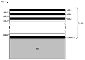
도 4는 예시적인 광학 필터(400)의 도면이다. 도 4는 고 굴절률 물질로서 수소화규소를 사용한 광학 필터의 예시적 적층을 도시한다. 도 4에 더 도시된 바와 같이, 광학 필터(400)는 광학 필터 코팅부(410) 및 기판(420)을 포함한다.4 is a diagram of an exemplary
광학 필터 코팅부(410)는 광학 필터층의 세트를 포함한다. 예를 들어, 광학 필터 코팅부(410)는 제1 세트의 층(430-1 내지 430-N, N≥1) 및 제2 세트의 층(440-1 내지 440-(N+1))을 포함한다. 층(430)은 수소화규소와 같은 고 굴절률 물질층(H층)의 세트를 포함할 수 있다. 층(440)은 이산화규소층, 산화알루미늄(Al2O3)층, 불화마그네슘(MgF2)층 등과 같은 저 굴절률 물질층(L 층)의 세트를 포함할 수 있다. 일부 실시형태에서, 층(430 및 440)은 (H-L) m (m ≥ 1) 순, (H-L) m -H 순, (L-H)m- 순, L-(H-L) m 순 등과 같이 특정 순서로 적층될 수 있다. 예를 들어, 도시된 바와 같이, 층(430 및 440)은 광학 필터(400)의 표면에 배치된 H 층 및 기판(420)의 표면에 배치된 H 층을 갖는 (H-L) n -H 순서로 위치한다.The
일부 실시형태에서, 광학 필터 코팅부(410)는 층의 특정 양, m과 관련될 수 있다. 예를 들어, 도 3과 관련하여 설명한 바와 같이, 수소화규소계 광학 필터는 H 층과 L 층이 교번하는 40개의 층을 포함할 수 있다. 다른 예에서, 광학 필터(400)는 10층 내지 100 층의 범위와 같이 층의 다른 양과 관련될 수 있다. 일부 실시형태에서, 광학 필터 코팅부(410)의 각 층은 특정 두께와 관련될 수 있다. 예를 들어, 층(430 및 440)은 각각 3㎚ 내지 300㎚ 사이의 두께와 관련될 수 있으며, 이에 따라 광학 필터 코팅부(410)는 1㎛ 내지 100㎛ 사이의 두께와 관련된다. 일부 실시형태에서, 층(430 및 440)은 층(430)에 대한 제1 두께 및 층(440)에 대한 제2 두께, 층(430)의 제1 서브세트에 대한 제1 두께 및 층(430)의 제2 서브세트에 대한 제2 두께, 층(440)의 제1 서브세트에 대한 제1 두께 및 층(440)의 제2 서브세트에 대한 제2 두께 등과 같은 다수의 두께와 관련될 수 있다. 이 경우, 층 두께 및/또는 층의 양은 의도된 통과대역, 의도된 반사율 등과 같은 의도된 광학적 특성 세트에 기초하여 선택될 수 있다. 예를 들어, 층 두께 및/또는 층의 양은 편광 빔분할기가 적어도 10㎚의 분리 대역폭을 갖는 대략 700㎚ 내지 대략 1,700㎚의 스펙트럼 범위에 이용될 수 있도록 선택될 수 있다.In some embodiments, the
일부 실시형태에서, H 층(430)에 대해 특정 수소화규소계 물질이 선택될 수 있다. 일부 실시형태에서, 층(430) 및/또는 440은 특정 스펙트럼 범위(예를 들어, 대략 800㎚ 내지 대략 1,100㎚의 스펙트럼 범위, 대략 900㎚ 내지 대략 1,000㎚의 스펙트럼 범위, 대략 954㎚의 파장 등)에 걸쳐서 대략 0.001 미만, 대략 0.0007 미만, 대략 0.0006 미만, 대략 0.0005 미만의 소광 계수(extinction coefficient), 대략 0.0003 미만의 소광 계수, 대략 0.0001 미만의 소광 계수 등과 같은 특정 소광 계수와 관련될 수 있다. 일부 실시형태에서, 층(430)은 특정 스펙트럼 범위(예를 들어, 대략 800㎚ 내지 대략 1,100㎚의 스펙트럼 범위, 대략 900㎚ 내지 대략 1,000㎚의 스펙트럼 범위, 대략 954㎚의 파장 등)에 걸쳐서 대략 3, 대략 3.5, 대략 3.6, 대략 3.7, 대략 3.75 등을 초과하는 굴절률을 포함하도록 선택 및/또는 제조될 수 있다. 다른 예에서, 층(430)은 대략 830㎚ 파장에서 대략 3.6의 굴절률을 포함하도록 선택될 수 있다. 일부 실시형태에서, 층(430) 및/또는 (440)은 광의 제1 부분(예를 들어, 대략 800㎚ 미만, 대략 700㎚ 미만 등)은 차단되고 광의 제2 부분(예를 들어, 대략 1,700㎚ 미만, 대략 1,550㎚, 대략 1,100㎚ 미만 등의 스펙트럼 범위)은 통과되게 하도록 제조될 수 있다.In some embodiments, a specific silicon hydride-based material may be selected for the
일부 실시형태에서, L 층(440)에 대해 특정 물질이 선택될 수 있다. 예를 들어, 층(440)은 이산화규소(SiO2)층의 세트, 산화알루미늄(Al2O3)층의 세트, 이산화티타늄(TiO2) 층의 세트, 오산화니노븀(Nb2O5)층의 세트, 오산화탄탈륨(Ta2O5)층의 세트, 불화마그네슘(MgF2)층의 세트 등을 포함할 수 있다. 이 경우, 층(440)은 예를 들어 특정 스펙트럼 범위(예를 들어, 대략 800㎚ 내지 대략 1,100㎚의 스펙트럼 범위, 대략 900㎚ 내지 대략 1,000㎚의 스펙트럼 범위, 대략 954㎚의 파장 등)에 걸쳐 층(430)의 굴절률보다 낮은 굴절률을 포함하도록 선택될 수 있다. 예를 들어, 층(440)은 특정 스펙트럼 범위(예를 들어, 대략 800㎚ 내지 대략 1,100㎚의 스펙트럼 범위, 대략 900㎚ 내지 대략 1,000㎚의 스펙트럼 범위, 대략 800㎚의 스펙트럼 범위, 대략 954㎚의 파장 등)에 걸쳐 3 미만의 굴절률과 관련되게 선택될 수 있다.In some embodiments, a specific material may be selected for the
다른 예에서, 층(440)은 특정 스펙트럼 범위(예를 들어, 대략 800㎚ 내지 대략 1,100㎚의 스펙트럼 범위, 대략 900㎚ 내지 대략 1,000㎚의 스펙트럼 범위, 대략 800㎚의 스펙트럼 범위, 대략 954㎚의 파장 등)에 걸쳐 2.5 미만의 굴절률과 관련되게 선택될 수 있다. 다른 예에서, 층(440)은 특정 스펙트럼 범위(예를 들어, 대략 800㎚ 내지 대략 1,100㎚의 스펙트럼 범위, 대략 900㎚ 내지 대략 1,000㎚의 스펙트럼 범위, 대략 800㎚의 스펙트럼 범위, 대략 954㎚의 파장 등)에 걸쳐 2 미만의 굴절률과 관련되게 선택될 수 있다. 다른 예에서, 층(440)은 특정 스펙트럼 범위(예를 들어, 대략 800㎚ 내지 대략 1,100㎚의 스펙트럼 범위, 대략 900㎚ 내지 대략 1,000㎚의 스펙트럼 범위, 대략 954㎚의 파장 등)에 걸쳐 1.5 미만의 굴절률과 관련되게 선택될 수 있다. 일부 실시형태에서, 대역 외 차단 스펙트럼 범위의 원하는 폭, AOI의 변화와 관련된 원하는 중심 파장 이동 등에 기초하여 L 층(440)에 대해 특정 물질이 선택될 수 있다.In another example,
일부 실시형태에서, 광학 필터 코팅부(410)는 스퍼터링(sputtering) 과정을 사용하여 제조될 수 있다. 예를 들어, 광학 필터 코팅부(410)는 펄스드-마그네트론(pulsed-magnetron) 기반의 스퍼터링 과정을 사용하여 유리 기판 상에 교번하는 층(430 및 440)을 스퍼터링함으로써 제조될 수 있다. 일부 실시형태에서, 광학 필터 코팅부(410)는 AOI의 변화로 비교적 낮은 중심 파장 이동과 관련될 수 있다. 예를 들어, 광학 필터 코팅부(410)는 입사각이 0° 내지 30°로 변화함에 따라 대략 20㎚, 대략 15㎜, 대략 12㎚ 등의 크기의 중심 파장 이동을 발생시킬 수 있다. 일부 실시형태에서, 광학 필터 코팅부(410)는 기판(420)과 같은 기판에 부착된다. 예를 들어, 광학 필터 코팅부(410)는 유리 기판에 부착될 수 있다. 일부 실시형태에서, 광학 필터 코팅부(410)는 공기 매체 또는 유리 매체와 같은 입사 매체와 관련될 수 있으며, 제1 편광 평면에서 50%를 초과하는 반사율을 가지고, 제2 편광 평면에서 50%를 초과하는 투과율을 가지고, 광학 필터(400)의 표면에 대한 입사광의 명목(nominal) AOI가 15° 내지 75°이며, 상기 명목 AOI에 대한 입사광의 각도 범위는 0° 내지 45°이다. 일부 실시형태에서, 광학 필터(400)는 프리즘 세트 사이에 배치될 수 있다.In some embodiments, the
일부 실시형태에서, 광학 필터 코팅부(410)를 제조하는 데 어닐링 과정이 이용될 수 있다. 예를 들어, 기판 상에 층(430 및 440)을 스퍼터링 증착한 후, 어닐링 과정이 수행되지 않은 다른 광학 필터에 비해 광학 필터(400)의 흡수 계수를 감소시키는 것과 같이, 광학 필터(400)의 하나 이상의 광학적 특성을 개선시키기 위해 광학 필터(400)는 어닐링될 수 있다.In some embodiments, an annealing process may be used to prepare the
위에서 나타낸 바와 같이, 도 4는 일례로서 제공된다. 다른 예가 가능하며 도 4와 관련하여 기술된 것과 다를 수 있다.As indicated above, FIG. 4 is provided as an example. Other examples are possible and may differ from that described with respect to FIG. 4 .
이러한 방식으로, 수소화규소층의 세트는 가시광의 대역 외 차단, NIR 광의 투과, 및 고 굴절률층의 세트에 사용되는 다른 유형의 물질에 비해 감소한 두께, 비용 및 제조 시간으로 편광 빔분할을 제공하기 위해 광학 필터의 광학 필터 코팅을 위한 고 지수 물질로서 사용될 수 있다. 또한, 수소화규소를 사용함으로써 대역 외 차단 및 대역 내 투과가 다른 유형의 물질에 비해 개선된다.In this way, the set of silicon hydride layers is designed to provide out-of-band blocking of visible light, transmission of NIR light, and polarization beam splitting with reduced thickness, cost, and manufacturing time compared to other types of materials used in the set of high refractive index layers. It can be used as a high index material for optical filter coatings of optical filters. In addition, out-of-band blocking and in-band transmission are improved compared to other types of materials by using silicon hydride.
전술한 개시는 도시 및 설명을 제공하지만, 개시된 정확한 형태로 구현을 제한하거나 포괄하고자 하는 것은 아니다. 수정 및 변형은 상기 개시 내용에 비추어 가능하거나 구현의 실행으로부터 얻어질 수 있다.The foregoing disclosure provides illustration and description, but is not intended to be exhaustive or to limit the implementation to the precise form disclosed. Modifications and variations are possible in light of the above disclosure or may be acquired from practice of implementation.
일부 실시형태는 임계값과 관련하여 여기에 설명된다. 본 명세서에서 사용된 바와 같이, 임계값을 만족하는 것은 임계값보다 크거나, 임계값보다 많거나, 임계값보다 높거나, 임계값 이상이거나, 임계값 미만이거나, 임계값보다 작거나, 임계값보다 적거나, 임계값 이하, 임계값과 같거나 등의 값을 나타낼 수 있다.Some embodiments are described herein with respect to thresholds. As used herein, satisfying a threshold is greater than a threshold, greater than a threshold, greater than a threshold, greater than or equal to a threshold, less than a threshold, less than a threshold, or less than a threshold. less than, less than a threshold, equal to or equal to a threshold, and the like.
특징의 특정 조합이 청구항에 청구되고/되거나 상세한 설명에 기재되어 있음에도 불구하고, 이들 조합은 가능한 실시형태의 개시를 제한하지 않는다. 사실, 이들 특징 중 다수는 구체적으로 청구항에 청구되고/되거나 상세한 설명에 기재되지 않은 방식으로 결합될 수 있다. 아래에 열거된 각각의 종속항이 단지 하나의 청구항에 직접적으로 의존할 수 있지만, 가능한 실시형태의 개시는 청구항 세트의 모든 다른 청구항과 함께 각각의 종속항을 포함한다.Notwithstanding that particular combinations of features are claimed in the claims and/or recited in the detailed description, these combinations do not limit the disclosure of possible embodiments. In fact, many of these features may be combined in ways not specifically claimed in the claims and/or not recited in the detailed description. Although each dependent claim listed below may depend directly on only one claim, the disclosure of possible embodiments includes each dependent claim along with all other claims of the set of claims.
본 명세서에서 사용되는 어떠한 요소, 동작 또는 명령도 명시적으로 기재되지 않는 한 결정적이거나 필수적이라고 해석되어서는 안 된다. 또한, 본 명세서에서 사용된 바와 같이, 단수 표현의 용어는 하나 이상의 아이템을 포함하도록 의도되며, "하나 또는 그 이상"과 상호 교환 가능하게 사용될 수 있다. 또한, 본 명세서에서 사용되는 바와 같이, "세트"라는 용어는 하나 이상의 아이템(예를 들어, 관련 아이템, 비 관련 아이템, 관련 아이템 및 비 관련 아이템의 조합)을 포함하도록 의도되며, "하나 이상"과 교환 가능하게 사용될 수 있다. 단 하나의 아이템이 의도된 경우, "하나" 또는 유사한 언어가 사용된다. 또한, 본 명세서에서 사용된 바와 같이, "가지다(has)", "가지다(have)", "갖는(having)" 등의 용어는 제한이 없는 용어로 의도된다. 또한, "~에 기초한"이라는 문구는 명시적으로 다르게 명시되지 않는 한, "적어도 부분적으로 기초하여"를 의미하는 것으로 의도된다.No element, act, or instruction used herein should be construed as critical or essential unless explicitly stated. Also, as used herein, terms in the singular are intended to include one or more items, and may be used interchangeably with "one or more". Also, as used herein, the term "set" is intended to include one or more items (eg, related items, unrelated items, combinations of related items and unrelated items), and "one or more" can be used interchangeably with Where only one item is intended, “one” or similar language is used. Also, as used herein, terms such as “has”, “have”, “having” and the like are intended to be non-limiting terms. Also, the phrase "based on" is intended to mean "based at least in part" unless expressly stated otherwise.
Claims (20)
층의 세트(set of layers)를 포함하되,
상기 층의 세트는 층의 제1 서브세트와 층의 제2 서브세트를 포함하며,
상기 층의 제1 서브세트는 제1 굴절률을 갖는 수소화규소(Si:H)를 포함하고;
상기 층의 제2 서브세트는 제2 굴절률을 갖는 물질을 포함하되, 상기 물질은 이산화규소(SiO2) 물질, 산화알루미늄(Al2O3) 물질, 이산화티타늄(TiO2) 물질, 오산화니노븀(Nb2O5) 물질, 오산화탄탈륨(Ta2O5) 물질 또는 불화마그네슘(MgF2) 물질 중 적어도 하나를 포함하고,
상기 제2 굴절률은 상기 제1 굴절률보다 낮으며, 상기 제2 굴절률은 대략 800나노미터(㎚) 내지 대략 1,100㎚의 스펙트럼 범위에서 3 미만이고,
상기 편광광학 코팅과 관련된, 입사광의 제1 편광이 s-평면에 있고,
상기 입사광의 제2 편광이 p-평면에 있고,
상기 편광광학 코팅은,
대략 890㎚ 내지 대략 940㎚ 또는
대략 930㎚ 내지 대략 960㎚
중 적어도 하나의 스펙트럼 범위 및 45도의 입사각에서 상기 입사광의 상기 제2 편광에 대해 95% 이상의 투과율과 관련되고,
상기 편광광학 코팅은, 상기 s-평면에서 상기 입사광에 대해서 95% 이상의 반사율과 관련되고,
상기 층의 제1 서브세트는 제1 두께와 관련된 제1 층을 포함하고,
상기 층의 제2 서브세트는 제2 두께와 관련된 제2 층을 포함하고,
상기 제1 두께 또는 상기 제2 두께 중 적어도 하나는 3㎚ 내지 300㎚이며,
상기 제2 두께는 상기 제1 두께와는 상이한, 편광광학 코팅.
A polarizing optical coating comprising:
including a set of layers;
wherein the set of layers comprises a first subset of layers and a second subset of layers;
the first subset of layers comprises silicon hydride (Si:H) having a first refractive index;
The second subset of layers comprises a material having a second index of refraction, wherein the material comprises a silicon dioxide (SiO 2 ) material, an aluminum oxide (Al 2 O 3 ) material, a titanium dioxide (TiO 2 ) material, a ninovium pentoxide material. (Nb 2 O 5 ) containing at least one of a material, a tantalum pentoxide (Ta 2 O 5 ) material, or a magnesium fluoride (MgF 2 ) material,
the second refractive index is lower than the first refractive index, the second refractive index is less than 3 in a spectral range of about 800 nanometers (nm) to about 1,100 nm;
a first polarization of incident light associated with the polarizing optical coating is in the s-plane,
a second polarization of the incident light is in the p-plane,
The polarizing optical coating is
about 890 nm to about 940 nm or
about 930 nm to about 960 nm
a transmittance of at least 95% for the second polarization of the incident light at an angle of incidence of 45 degrees and a spectral range of at least one of
wherein the polarizing optical coating relates to a reflectivity of at least 95% for the incident light in the s-plane,
wherein the first subset of layers comprises a first layer associated with a first thickness;
wherein the second subset of layers comprises a second layer associated with a second thickness;
At least one of the first thickness or the second thickness is 3 nm to 300 nm,
and the second thickness is different from the first thickness.
상기 층의 제1 서브세트는 고 굴절률층(H)이고, 상기 층의 제2 서브세트는 저 굴절률층(L)이며,
상기 층의 세트는 (H-L) m 순서, (H-L) m -H 순서, (L-H)m 순서 또는 L-(H-L) m 순서 중 적어도 하나로 배열되되,
m은 층의 양(quantity of layers)이고,
상기 층의 양은 의도된 세트의 광학적 특성에 기초하여 선택되는, 편광광학 코팅.According to claim 1,
a first subset of said layers is a high refractive index layer (H) and a second subset of said layers is a low refractive index layer (L);
wherein the set of layers is arranged in at least one of (HL) m order, (HL) m -H order, (LH) m order, or L-(HL) m order,
m is the quantity of layers,
and the amount of said layer is selected based on the intended set of optical properties.
대략 890㎚ 내지 대략 940㎚ 또는
대략 930㎚ 내지 대략 960㎚
중 적어도 하나의 스펙트럼 범위에서,
제1 편광 평면에서의 50% 초과의 반사와 제2 편광 평면에서의 50% 초과의 투과와 관련되되,
상기 제1 편광 평면은 상기 제2 편광 평면에 직교하는, 편광광학 코팅.According to claim 1, wherein the polarizing optical coating,
about 890 nm to about 940 nm or
about 930 nm to about 960 nm
In at least one spectral range of
associated with greater than 50% reflection in the first polarization plane and greater than 50% transmission in the second polarization plane;
and the first polarization plane is orthogonal to the second polarization plane.
기판; 및
대략 800나노미터(㎚) 미만의 스펙트럼 범위를 갖는 입사광의 제1 편광이 상기 광학 필터에 의해 반사되고, 대략 800㎚를 초과하는 스펙트럼 범위를 갖는 입사광의 제2 편광이 상기 광학 필터를 통과하게끔, 편광 빔이 입사광을 분할하도록 기판 상에 배치된 교번하는 고 굴절률층 및 저 굴절률층의 세트를 포함하되,
상기 입사광의 제1 편광이 s-평면에 있고,
상기 입사광의 제2 편광이 p-평면에 있고,
상기 광학 필터는,
대략 890㎚ 내지 대략 940㎚ 또는
대략 930㎚ 내지 대략 960㎚
중 적어도 하나의 스펙트럼 범위 및 45도의 입사각에서 상기 입사광의 상기 제2 편광에 대해 95% 이상의 투과율과 관련되고,
상기 광학 필터는, 상기 s-평면에서 상기 입사광에 대해서 95% 이상의 반사율과 관련되고,
상기 고 굴절률층은 수소화규소(Si:H)이고,
상기 저 굴절률층은 이산화규소(SiO2)이고,
상기 광학 필터는 상기 고 굴절률층과 상기 저 굴절률층의 층의 양과 연관되고,
상기 층의 양은 10개 층 내지 100개 층의 범위이고, 상기 제1 두께 또는 상기 제2 두께 중 적어도 하나는 3㎚ 내지 300㎚인, 광학 필터.
An optical filter comprising:
Board; and
a first polarization of incident light having a spectral range less than about 800 nanometers (nm) is reflected by the optical filter and a second polarization of incident light having a spectral range greater than about 800 nm passes through the optical filter; a set of alternating high and low refractive index layers disposed on the substrate such that the polarizing beam splits incident light;
a first polarization of the incident light is in the s-plane,
a second polarization of the incident light is in the p-plane,
The optical filter is
about 890 nm to about 940 nm or
about 930 nm to about 960 nm
a transmittance of at least 95% for the second polarization of the incident light at an angle of incidence of 45 degrees and a spectral range of at least one of
wherein the optical filter relates to a reflectivity of at least 95% for the incident light in the s-plane,
The high refractive index layer is silicon hydride (Si:H),
The low refractive index layer is silicon dioxide (SiO 2 ),
wherein the optical filter is associated with the amount of layers of the high refractive index layer and the low refractive index layer;
wherein the amount of layers ranges from 10 to 100 layers, and wherein at least one of the first thickness or the second thickness is between 3 nm and 300 nm.
상기 광학 필터는 대략 890㎚ 내지 대략 940㎚의 스펙트럼 범위에서 상기 입사광의 제2 편광에 대해 99% 이상의 투과율과 관련되고, 그리고
상기 광학 필터는 상기 s-평면에서의 상기 입사광에 대해 99% 이상의 반사율과 관련되는, 광학 필터.17. The method of claim 16,
wherein the optical filter is associated with a transmittance of at least 99% for a second polarization of the incident light in a spectral range of about 890 nm to about 940 nm, and
wherein the optical filter relates to a reflectivity of at least 99% for the incident light in the s-plane.
제스처 인식을 위하여 사람 쪽으로, 차량 또는 사람 근처에서 물체를 검출하기 위하여 물체 쪽으로, 또는 LIDAR 기술을 이용해서 상기 물체에 대한 접근을 검출하기 위하여 상기 물체 쪽으로 근적외선(near-infrared: NIR) 광을 방출하는 광 송신기;
입력 광학 신호를 필터링하고 필터링된 입력 광학 신호를 제공하는 편광광학 필터; 및
상기 필터링된 입력 광학 신호를 수신하고 출력 전기 신호를 제공하는 광 수신기를 포함하되,
상기 입력 광학 신호는 상기 광 송신기로부터의 NIR 광 및 다른 광원으로부터의 주변 광을 포함하고,
상기 편광광학 필터는 유전체 박막층의 세트를 포함하되,
상기 유전체 박막층의 세트는,
제1 굴절률을 갖는 수소화규소층의 제1 서브세트,
상기 제1 굴절률보다 작은 제2 굴절률을 갖는 물질의 층의 제2 서브세트를 포함하되, 상기 물질은 이산화규소(SiO2) 물질, 산화알루미늄(Al2O3) 물질, 이산화티타늄(TiO2) 물질, 오산화니노븀(Nb2O5) 물질, 오산화탄탈륨(Ta2O5) 물질 또는 불화마그네슘(MgF2) 물질 중 적어도 하나를 포함하고, 상기 제2 굴절률은 대략 800나노미터(㎚) 내지 대략 1,100㎚의 스펙트럼 범위에서 3 미만이고,
상기 편광광학 필터와 관련된, 입사광의 제1 편광이 s-평면에 있고,
상기 입사광의 제2 편광이 p-평면에 있고,
상기 편광광학 필터는,
대략 890㎚ 내지 대략 940㎚ 또는
대략 930㎚ 내지 대략 960㎚
중 적어도 하나의 스펙트럼 범위 및 45도의 입사각에서 상기 입사광의 상기 제2 편광에 대해 95% 이상의 투과율과 관련되고,
상기 편광광학 필터는, 상기 s-평면에서 상기 입사광에 대해서 95% 이상의 반사율과 관련되고,
상기 층의 제1 서브세트는 제1 두께와 관련된 제1 층을 포함하고,
상기 층의 제2 서브세트는 제2 두께와 관련된 제2 층을 포함하고,
상기 제1 두께 또는 상기 제2 두께 중 적어도 하나는 3㎚ 내지 300㎚이며,
상기 제2 두께는 상기 제1 두께와는 상이한, 광학 시스템.An optical system comprising:
Emitting near-infrared (NIR) light towards a person for gesture recognition, towards an object to detect an object near a vehicle or person, or towards the object to detect approach to the object using LIDAR technology. optical transmitter;
a polarization optical filter that filters the input optical signal and provides the filtered input optical signal; and
an optical receiver receiving the filtered input optical signal and providing an output electrical signal;
the input optical signal comprises NIR light from the optical transmitter and ambient light from another light source;
The polarizing optical filter comprises a set of dielectric thin film layers,
The set of dielectric thin film layers,
a first subset of silicon hydride layers having a first refractive index;
a second subset of layers of a material having a second index of refraction less than the first index of refraction, wherein the material is a silicon dioxide (SiO 2 ) material, an aluminum oxide (Al 2 O 3 ) material, a titanium dioxide (TiO 2 ) material; a material, at least one of a ninovium pentoxide (Nb 2 O 5 ) material, a tantalum pentoxide (Ta 2 O 5 ) material, or a magnesium fluoride (MgF 2 ) material, wherein the second refractive index is approximately 800 nanometers (nm) to less than 3 in the spectral range of approximately 1,100 nm,
a first polarization of incident light associated with the polarizing optical filter is in the s-plane;
a second polarization of the incident light is in the p-plane,
The polarizing optical filter,
about 890 nm to about 940 nm or
about 930 nm to about 960 nm
a transmittance of at least 95% for the second polarization of the incident light at an angle of incidence of 45 degrees and a spectral range of at least one of
wherein the polarizing optical filter relates to a reflectivity of at least 95% with respect to the incident light in the s-plane,
wherein the first subset of layers comprises a first layer associated with a first thickness;
wherein the second subset of layers comprises a second layer associated with a second thickness;
At least one of the first thickness or the second thickness is 3 nm to 300 nm,
and the second thickness is different from the first thickness.
Applications Claiming Priority (2)
| Application Number | Priority Date | Filing Date | Title |
|---|---|---|---|
| US15/431,344 US10914961B2 (en) | 2017-02-13 | 2017-02-13 | Optical polarizing filter |
| US15/431,344 | 2017-02-13 |
Publications (2)
| Publication Number | Publication Date |
|---|---|
| KR20180093805A KR20180093805A (en) | 2018-08-22 |
| KR102444466B1 true KR102444466B1 (en) | 2022-09-19 |
Family
ID=61024626
Family Applications (1)
| Application Number | Title | Priority Date | Filing Date |
|---|---|---|---|
| KR1020180015916A KR102444466B1 (en) | 2017-02-13 | 2018-02-08 | Optical polarizing filter |
Country Status (9)
| Country | Link |
|---|---|
| US (1) | US10914961B2 (en) |
| EP (1) | EP3361295B1 (en) |
| JP (1) | JP6932656B2 (en) |
| KR (1) | KR102444466B1 (en) |
| CN (1) | CN108427154B (en) |
| AU (2) | AU2018200642A1 (en) |
| CA (1) | CA2993063A1 (en) |
| HK (1) | HK1251665A1 (en) |
| TW (1) | TWI735736B (en) |
Families Citing this family (13)
| Publication number | Priority date | Publication date | Assignee | Title |
|---|---|---|---|---|
| CN110579829A (en) * | 2018-07-26 | 2019-12-17 | 蓝思科技(长沙)有限公司 | Near-infrared filter, preparation method thereof and filtering equipment |
| CN109270616B (en) * | 2018-10-25 | 2021-02-26 | 杭州灯之塔科技有限公司 | Multi-valley transmission element and preparation method thereof |
| JP7251099B2 (en) * | 2018-10-31 | 2023-04-04 | 日本電気硝子株式会社 | Bandpass filter and manufacturing method thereof |
| US10962694B2 (en) | 2018-11-02 | 2021-03-30 | Viavi Solutions Inc. | Stepped structure optical filter |
| CN111290064A (en) * | 2018-11-22 | 2020-06-16 | 福州高意光学有限公司 | Polarization-independent optical filter |
| CN112114394B (en) * | 2019-06-21 | 2023-03-31 | 福州高意光学有限公司 | Optical filter and sensor system with temperature compensation effect |
| KR102151947B1 (en) * | 2019-07-26 | 2020-09-04 | 송영진 | Optical filter and sensor system having the same, and halogenated amorphous silicon film manufacturing method for optical filter |
| CN110456440A (en) * | 2019-08-28 | 2019-11-15 | 山东劳动职业技术学院(山东劳动技师学院) | A kind of infrared polarizer of three layer line grid structure of metal-dielectric-metal |
| CN113126405B (en) * | 2019-12-31 | 2022-12-27 | 华为技术有限公司 | Projection device and projection interaction method |
| CN114089460A (en) * | 2020-08-24 | 2022-02-25 | 福州高意光学有限公司 | Low-angle offset optical filter |
| CN112130340B (en) * | 2020-09-29 | 2022-08-16 | 苏州众为光电有限公司 | Polarization beam splitter of ultra wide band |
| CN112130339B (en) * | 2020-09-29 | 2022-08-12 | 苏州众为光电有限公司 | Laser polarization beam combination system |
| WO2022200190A1 (en) | 2021-03-25 | 2022-09-29 | Schott Ag | Near infrared transparent, visible light absorptive coating and glass substrate with coating |
Citations (1)
| Publication number | Priority date | Publication date | Assignee | Title |
|---|---|---|---|---|
| JP2003302521A (en) | 2002-04-11 | 2003-10-24 | Nippon Telegr & Teleph Corp <Ntt> | Optical multilayered film filter |
Family Cites Families (22)
| Publication number | Priority date | Publication date | Assignee | Title |
|---|---|---|---|---|
| EP0573905A1 (en) | 1992-06-08 | 1993-12-15 | Minnesota Mining And Manufacturing Company | Retroreflecting polarizer for presentation systems |
| JPH06214115A (en) * | 1993-01-13 | 1994-08-05 | Sony Corp | Image pickup device |
| US5882774A (en) | 1993-12-21 | 1999-03-16 | Minnesota Mining And Manufacturing Company | Optical film |
| US5912762A (en) * | 1996-08-12 | 1999-06-15 | Li; Li | Thin film polarizing device |
| JPH1123842A (en) * | 1997-07-03 | 1999-01-29 | Minolta Co Ltd | Polarization beam splitter, lighting optical system with the same polarization beam splitter, and projector |
| JP4574439B2 (en) * | 2004-08-09 | 2010-11-04 | キヤノン株式会社 | Polarization separating element and projection apparatus having the same |
| CA2736292A1 (en) | 2008-09-08 | 2010-03-11 | National Research Council Of Canada | Thin film optical filters with an integral air layer |
| EP2507599A1 (en) | 2009-11-30 | 2012-10-10 | Imec | Integrated circuit for spectral imaging system |
| WO2012007147A1 (en) | 2010-07-15 | 2012-01-19 | Fraunhofer-Gesellschaft Zur Förderung Der Angewandten Forschung E.V. . | Optical bandpass filter system, in particular for multichannel spectral-selective measurements |
| EP2776797B1 (en) | 2011-11-04 | 2018-12-05 | IMEC vzw | Spectral camera with overlapping segments of image copies interleaved onto sensor array |
| IN2014CN03172A (en) | 2011-11-04 | 2015-07-03 | Imec | |
| EP2776798B1 (en) | 2011-11-04 | 2023-12-13 | IMEC vzw | Spectral camera with integrated filters and multiple adjacent image copies projected onto sensor array |
| TWI648561B (en) * | 2012-07-16 | 2019-01-21 | 美商唯亞威方案公司 | Optical filter and sensor system |
| JP6214115B2 (en) | 2013-07-31 | 2017-10-18 | 株式会社潤工社 | Cable support member |
| US9212996B2 (en) | 2013-08-05 | 2015-12-15 | Tellspec, Inc. | Analyzing and correlating spectra, identifying samples and their ingredients, and displaying related personalized information |
| US9645075B2 (en) | 2013-11-26 | 2017-05-09 | nanoLambda Korea | Multispectral imager with hybrid double layer filter array |
| EP3259626B1 (en) | 2015-02-18 | 2021-04-21 | Materion Corporation | Near infrared optical interference filters with improved transmission |
| CN105388625B (en) * | 2015-12-23 | 2018-11-13 | 浙江大学 | A kind of wearing display beam splitter and preparation method thereof |
| US10168459B2 (en) * | 2016-11-30 | 2019-01-01 | Viavi Solutions Inc. | Silicon-germanium based optical filter |
| US11215741B2 (en) * | 2018-01-17 | 2022-01-04 | Viavi Solutions Inc. | Angle of incidence restriction for optical filters |
| US11009636B2 (en) * | 2018-03-13 | 2021-05-18 | Viavi Solutions Inc. | Sensor window to provide different opacity and transmissivity at different spectral ranges |
| US10948640B2 (en) * | 2018-03-13 | 2021-03-16 | Viavi Solutions Inc. | Sensor window with a set of layers configured to a particular color and associated with a threshold opacity in a visible spectral range wherein the color is a color-matched to a surface adjacent to the sensor window |
-
2017
- 2017-02-13 US US15/431,344 patent/US10914961B2/en active Active
-
2018
- 2018-01-24 JP JP2018009735A patent/JP6932656B2/en active Active
- 2018-01-24 EP EP18153121.1A patent/EP3361295B1/en active Active
- 2018-01-25 TW TW107102717A patent/TWI735736B/en active
- 2018-01-25 AU AU2018200642A patent/AU2018200642A1/en not_active Abandoned
- 2018-01-26 CA CA2993063A patent/CA2993063A1/en active Pending
- 2018-02-08 KR KR1020180015916A patent/KR102444466B1/en active IP Right Grant
- 2018-02-13 CN CN201810149226.6A patent/CN108427154B/en active Active
- 2018-08-22 HK HK18110819.8A patent/HK1251665A1/en unknown
-
2023
- 2023-02-08 AU AU2023200691A patent/AU2023200691A1/en active Pending
Patent Citations (1)
| Publication number | Priority date | Publication date | Assignee | Title |
|---|---|---|---|---|
| JP2003302521A (en) | 2002-04-11 | 2003-10-24 | Nippon Telegr & Teleph Corp <Ntt> | Optical multilayered film filter |
Also Published As
| Publication number | Publication date |
|---|---|
| US10914961B2 (en) | 2021-02-09 |
| US20180231791A1 (en) | 2018-08-16 |
| CN108427154A (en) | 2018-08-21 |
| JP6932656B2 (en) | 2021-09-08 |
| EP3361295A3 (en) | 2018-11-14 |
| TW201841002A (en) | 2018-11-16 |
| EP3361295A2 (en) | 2018-08-15 |
| EP3361295B1 (en) | 2023-03-15 |
| AU2023200691A1 (en) | 2023-03-09 |
| KR20180093805A (en) | 2018-08-22 |
| CN108427154B (en) | 2021-12-28 |
| CA2993063A1 (en) | 2018-08-13 |
| HK1251665A1 (en) | 2019-02-01 |
| JP2018132760A (en) | 2018-08-23 |
| AU2018200642A1 (en) | 2018-08-30 |
| TWI735736B (en) | 2021-08-11 |
Similar Documents
| Publication | Publication Date | Title |
|---|---|---|
| KR102444466B1 (en) | Optical polarizing filter | |
| KR20220059457A (en) | Silicon-germanium based optical filter | |
| JP7404367B2 (en) | optical filter | |
| US11733442B2 (en) | Optical filter | |
| JP2018132760A5 (en) | ||
| US20210302635A1 (en) | Low angle shift filter | |
| KR20190015378A (en) | Optical filters with spatially varying fine-cloned layers | |
| KR20230104573A (en) | Argon-helium based coating | |
| US11215741B2 (en) | Angle of incidence restriction for optical filters |
Legal Events
| Date | Code | Title | Description |
|---|---|---|---|
| A201 | Request for examination | ||
| A302 | Request for accelerated examination | ||
| E902 | Notification of reason for refusal | ||
| E902 | Notification of reason for refusal | ||
| E902 | Notification of reason for refusal | ||
| E701 | Decision to grant or registration of patent right | ||
| GRNT | Written decision to grant |