KR102393787B1 - Heart valve restoration device and method of implanting same - Google Patents
Heart valve restoration device and method of implanting same Download PDFInfo
- Publication number
- KR102393787B1 KR102393787B1 KR1020197001197A KR20197001197A KR102393787B1 KR 102393787 B1 KR102393787 B1 KR 102393787B1 KR 1020197001197 A KR1020197001197 A KR 1020197001197A KR 20197001197 A KR20197001197 A KR 20197001197A KR 102393787 B1 KR102393787 B1 KR 102393787B1
- Authority
- KR
- South Korea
- Prior art keywords
- neo
- heart
- heart valve
- valve
- delete delete
- Prior art date
Links
Images


Classifications
-
- A—HUMAN NECESSITIES
- A61—MEDICAL OR VETERINARY SCIENCE; HYGIENE
- A61F—FILTERS IMPLANTABLE INTO BLOOD VESSELS; PROSTHESES; DEVICES PROVIDING PATENCY TO, OR PREVENTING COLLAPSING OF, TUBULAR STRUCTURES OF THE BODY, e.g. STENTS; ORTHOPAEDIC, NURSING OR CONTRACEPTIVE DEVICES; FOMENTATION; TREATMENT OR PROTECTION OF EYES OR EARS; BANDAGES, DRESSINGS OR ABSORBENT PADS; FIRST-AID KITS
- A61F2/00—Filters implantable into blood vessels; Prostheses, i.e. artificial substitutes or replacements for parts of the body; Appliances for connecting them with the body; Devices providing patency to, or preventing collapsing of, tubular structures of the body, e.g. stents
- A61F2/02—Prostheses implantable into the body
- A61F2/24—Heart valves ; Vascular valves, e.g. venous valves; Heart implants, e.g. passive devices for improving the function of the native valve or the heart muscle; Transmyocardial revascularisation [TMR] devices; Valves implantable in the body
- A61F2/2442—Annuloplasty rings or inserts for correcting the valve shape; Implants for improving the function of a native heart valve
- A61F2/246—Devices for obstructing a leak through a native valve in a closed condition
-
- A—HUMAN NECESSITIES
- A61—MEDICAL OR VETERINARY SCIENCE; HYGIENE
- A61F—FILTERS IMPLANTABLE INTO BLOOD VESSELS; PROSTHESES; DEVICES PROVIDING PATENCY TO, OR PREVENTING COLLAPSING OF, TUBULAR STRUCTURES OF THE BODY, e.g. STENTS; ORTHOPAEDIC, NURSING OR CONTRACEPTIVE DEVICES; FOMENTATION; TREATMENT OR PROTECTION OF EYES OR EARS; BANDAGES, DRESSINGS OR ABSORBENT PADS; FIRST-AID KITS
- A61F2/00—Filters implantable into blood vessels; Prostheses, i.e. artificial substitutes or replacements for parts of the body; Appliances for connecting them with the body; Devices providing patency to, or preventing collapsing of, tubular structures of the body, e.g. stents
- A61F2/02—Prostheses implantable into the body
- A61F2/24—Heart valves ; Vascular valves, e.g. venous valves; Heart implants, e.g. passive devices for improving the function of the native valve or the heart muscle; Transmyocardial revascularisation [TMR] devices; Valves implantable in the body
- A61F2/2442—Annuloplasty rings or inserts for correcting the valve shape; Implants for improving the function of a native heart valve
- A61F2/2466—Delivery devices therefor
-
- A—HUMAN NECESSITIES
- A61—MEDICAL OR VETERINARY SCIENCE; HYGIENE
- A61F—FILTERS IMPLANTABLE INTO BLOOD VESSELS; PROSTHESES; DEVICES PROVIDING PATENCY TO, OR PREVENTING COLLAPSING OF, TUBULAR STRUCTURES OF THE BODY, e.g. STENTS; ORTHOPAEDIC, NURSING OR CONTRACEPTIVE DEVICES; FOMENTATION; TREATMENT OR PROTECTION OF EYES OR EARS; BANDAGES, DRESSINGS OR ABSORBENT PADS; FIRST-AID KITS
- A61F2/00—Filters implantable into blood vessels; Prostheses, i.e. artificial substitutes or replacements for parts of the body; Appliances for connecting them with the body; Devices providing patency to, or preventing collapsing of, tubular structures of the body, e.g. stents
- A61F2/02—Prostheses implantable into the body
- A61F2/24—Heart valves ; Vascular valves, e.g. venous valves; Heart implants, e.g. passive devices for improving the function of the native valve or the heart muscle; Transmyocardial revascularisation [TMR] devices; Valves implantable in the body
- A61F2/2412—Heart valves ; Vascular valves, e.g. venous valves; Heart implants, e.g. passive devices for improving the function of the native valve or the heart muscle; Transmyocardial revascularisation [TMR] devices; Valves implantable in the body with soft flexible valve members, e.g. tissue valves shaped like natural valves
-
- A—HUMAN NECESSITIES
- A61—MEDICAL OR VETERINARY SCIENCE; HYGIENE
- A61F—FILTERS IMPLANTABLE INTO BLOOD VESSELS; PROSTHESES; DEVICES PROVIDING PATENCY TO, OR PREVENTING COLLAPSING OF, TUBULAR STRUCTURES OF THE BODY, e.g. STENTS; ORTHOPAEDIC, NURSING OR CONTRACEPTIVE DEVICES; FOMENTATION; TREATMENT OR PROTECTION OF EYES OR EARS; BANDAGES, DRESSINGS OR ABSORBENT PADS; FIRST-AID KITS
- A61F2/00—Filters implantable into blood vessels; Prostheses, i.e. artificial substitutes or replacements for parts of the body; Appliances for connecting them with the body; Devices providing patency to, or preventing collapsing of, tubular structures of the body, e.g. stents
- A61F2/02—Prostheses implantable into the body
- A61F2/24—Heart valves ; Vascular valves, e.g. venous valves; Heart implants, e.g. passive devices for improving the function of the native valve or the heart muscle; Transmyocardial revascularisation [TMR] devices; Valves implantable in the body
- A61F2/2427—Devices for manipulating or deploying heart valves during implantation
- A61F2/243—Deployment by mechanical expansion
- A61F2/2433—Deployment by mechanical expansion using balloon catheter
-
- A—HUMAN NECESSITIES
- A61—MEDICAL OR VETERINARY SCIENCE; HYGIENE
- A61F—FILTERS IMPLANTABLE INTO BLOOD VESSELS; PROSTHESES; DEVICES PROVIDING PATENCY TO, OR PREVENTING COLLAPSING OF, TUBULAR STRUCTURES OF THE BODY, e.g. STENTS; ORTHOPAEDIC, NURSING OR CONTRACEPTIVE DEVICES; FOMENTATION; TREATMENT OR PROTECTION OF EYES OR EARS; BANDAGES, DRESSINGS OR ABSORBENT PADS; FIRST-AID KITS
- A61F2/00—Filters implantable into blood vessels; Prostheses, i.e. artificial substitutes or replacements for parts of the body; Appliances for connecting them with the body; Devices providing patency to, or preventing collapsing of, tubular structures of the body, e.g. stents
- A61F2/95—Instruments specially adapted for placement or removal of stents or stent-grafts
-
- A—HUMAN NECESSITIES
- A61—MEDICAL OR VETERINARY SCIENCE; HYGIENE
- A61F—FILTERS IMPLANTABLE INTO BLOOD VESSELS; PROSTHESES; DEVICES PROVIDING PATENCY TO, OR PREVENTING COLLAPSING OF, TUBULAR STRUCTURES OF THE BODY, e.g. STENTS; ORTHOPAEDIC, NURSING OR CONTRACEPTIVE DEVICES; FOMENTATION; TREATMENT OR PROTECTION OF EYES OR EARS; BANDAGES, DRESSINGS OR ABSORBENT PADS; FIRST-AID KITS
- A61F2/00—Filters implantable into blood vessels; Prostheses, i.e. artificial substitutes or replacements for parts of the body; Appliances for connecting them with the body; Devices providing patency to, or preventing collapsing of, tubular structures of the body, e.g. stents
- A61F2/02—Prostheses implantable into the body
- A61F2/24—Heart valves ; Vascular valves, e.g. venous valves; Heart implants, e.g. passive devices for improving the function of the native valve or the heart muscle; Transmyocardial revascularisation [TMR] devices; Valves implantable in the body
- A61F2/2442—Annuloplasty rings or inserts for correcting the valve shape; Implants for improving the function of a native heart valve
- A61F2/2454—Means for preventing inversion of the valve leaflets, e.g. chordae tendineae prostheses
-
- A—HUMAN NECESSITIES
- A61—MEDICAL OR VETERINARY SCIENCE; HYGIENE
- A61F—FILTERS IMPLANTABLE INTO BLOOD VESSELS; PROSTHESES; DEVICES PROVIDING PATENCY TO, OR PREVENTING COLLAPSING OF, TUBULAR STRUCTURES OF THE BODY, e.g. STENTS; ORTHOPAEDIC, NURSING OR CONTRACEPTIVE DEVICES; FOMENTATION; TREATMENT OR PROTECTION OF EYES OR EARS; BANDAGES, DRESSINGS OR ABSORBENT PADS; FIRST-AID KITS
- A61F2/00—Filters implantable into blood vessels; Prostheses, i.e. artificial substitutes or replacements for parts of the body; Appliances for connecting them with the body; Devices providing patency to, or preventing collapsing of, tubular structures of the body, e.g. stents
- A61F2/82—Devices providing patency to, or preventing collapsing of, tubular structures of the body, e.g. stents
- A61F2/86—Stents in a form characterised by the wire-like elements; Stents in the form characterised by a net-like or mesh-like structure
- A61F2/90—Stents in a form characterised by the wire-like elements; Stents in the form characterised by a net-like or mesh-like structure characterised by a net-like or mesh-like structure
-
- A—HUMAN NECESSITIES
- A61—MEDICAL OR VETERINARY SCIENCE; HYGIENE
- A61F—FILTERS IMPLANTABLE INTO BLOOD VESSELS; PROSTHESES; DEVICES PROVIDING PATENCY TO, OR PREVENTING COLLAPSING OF, TUBULAR STRUCTURES OF THE BODY, e.g. STENTS; ORTHOPAEDIC, NURSING OR CONTRACEPTIVE DEVICES; FOMENTATION; TREATMENT OR PROTECTION OF EYES OR EARS; BANDAGES, DRESSINGS OR ABSORBENT PADS; FIRST-AID KITS
- A61F2220/00—Fixations or connections for prostheses classified in groups A61F2/00 - A61F2/26 or A61F2/82 or A61F9/00 or A61F11/00 or subgroups thereof
- A61F2220/0008—Fixation appliances for connecting prostheses to the body
-
- A—HUMAN NECESSITIES
- A61—MEDICAL OR VETERINARY SCIENCE; HYGIENE
- A61F—FILTERS IMPLANTABLE INTO BLOOD VESSELS; PROSTHESES; DEVICES PROVIDING PATENCY TO, OR PREVENTING COLLAPSING OF, TUBULAR STRUCTURES OF THE BODY, e.g. STENTS; ORTHOPAEDIC, NURSING OR CONTRACEPTIVE DEVICES; FOMENTATION; TREATMENT OR PROTECTION OF EYES OR EARS; BANDAGES, DRESSINGS OR ABSORBENT PADS; FIRST-AID KITS
- A61F2250/00—Special features of prostheses classified in groups A61F2/00 - A61F2/26 or A61F2/82 or A61F9/00 or A61F11/00 or subgroups thereof
- A61F2250/0003—Special features of prostheses classified in groups A61F2/00 - A61F2/26 or A61F2/82 or A61F9/00 or A61F11/00 or subgroups thereof having an inflatable pocket filled with fluid, e.g. liquid or gas
Abstract
본 발명은 환자의 심장 판막에 대하여 상부에 위치하는 적어도 하나의 조직 부위에 고정하기에 적합한 적어도 하나의 상부 고정 수단; 및 상기 상부 고정 수단으로부터 연장되어 배치되고 자유 말단을 포함하는 접합 구조물을 포함하는 심장 판막 회복을 위한 장치에 관한 것으로, 상기 접합 구조물은 심장 판막을 가로 질러 연장하도록 작동하고 자유 말단을 심장 판막의 하부에 위치시키며 상기 접합 구조물은 환자 심장의 적어도 하나의 심장 판막 첨판과 접합하도록 작동하여 혈액의 역류를 방지 및/또는 최소화한다. 본 발명은 최소 침습적 접근법을 사용하여 심장 판막의 치료에 적합하다. 또한, 본 발명은 환자 심장에 있는 심장 판막 회복을 위한 장치를 임플란트하는 방법에 관한 것이다.The present invention relates to at least one upper fixation means suitable for fixation to at least one tissue site located thereon with respect to a heart valve of a patient; and a bonding structure disposed extending from the upper anchoring means and comprising a free end, the bonding structure operative to extend across the heart valve and extending the free end to the lower portion of the heart valve. and wherein the bonding structure is operative to bond with at least one heart valve leaflet of a patient's heart to prevent and/or minimize backflow of blood. The present invention is suitable for the treatment of heart valves using a minimally invasive approach. The invention also relates to a method of implanting a device for heart valve repair in a patient's heart.

Description
본 발명은 임플란트 가능한 의료 장치 분야와 관련되고 특히 심장 판막 회복 장치 및 이를 임플란트하는 방법에 관한 것이다. 본 발명은 트랜스카테터 및 최소 침습적 심장 판막 치료에 적합하고, 특히 기능하지 않는 삼첨판 또는 승모판의 회복에 적합하다.The present invention relates to the field of implantable medical devices and more particularly to heart valve restoration devices and methods of implanting them. The present invention is suitable for transcatheter and minimally invasive heart valve treatment, and is particularly suitable for the repair of malfunctioning tricuspid or mitral valves.
이론적 근거rationale
삼첨판 역류(Tricuspid regurgitation, TR)는 전세계 수백만명의 사람들에게 영향을 준다. 치료가 어렵고 수술적 복원도 실패할 수 있다. 일부 연구들에서는 수술적 복원을 받은 환자에서 에서 최대 30 %의 심각한 재발성 TR로 장기간 중등도(moderate)을 보였다. TR은 폐 고혈압, 우심부전, 간경변증 및 우심부전과 관련된 합병증 (예: 정맥 궤양)과 같은 심각한 합병증을 초래할 수 있다. 현재 치료법은 대부분 라식스(Lasix) 및 스피로노락톤(spironolactone)과 같은 이뇨제를 사용하는 약물 치료이다. 다른 치료법보다 하나의 치료법의 우월성을 보여주는 랜덤 시험은 없었다.Tricuspid regurgitation (TR) affects millions of people worldwide. Treatment is difficult and surgical restoration may fail. Some studies have shown moderate long-term, severe recurrent TR of up to 30% in patients who underwent surgical restoration. TR can lead to serious complications such as pulmonary hypertension, right heart failure, cirrhosis and complications associated with right heart failure (eg, venous ulcers). Current treatment is mostly drug treatment with diuretics such as Lasix and spironolactone. There were no randomized trials showing superiority of one treatment over another.
TR의 문제점은 거의 분리되어 있지 않다는 것이다. 그것은 종종 다른 판막 심장 질환과 함께 또는 심장 마비 또는 폐 고혈압과 함께 발생한다. 수술이 원발성 판막 질환에 대해 수행되면, 삼첨판이 동시에 회복되거나 교체될 수 있다. 그러나, 많은 환자들에게 있어 심각한 TR의 발달은 늦은 징후이며, 1차 병변이 치료되더라도 TR은 여전히 문제가 될 수 있다. 이것은 우심실 및 삼첨판 륜(tricuspid annulus)이 리모델링되어 거의 되돌아 가지 않기 때문이다. 다른 경우에, 근원적인 병리, 예를 들면 원발성 폐 고혈압 또는 허혈성 심근 병증은 역전될 수 없지만, 2차 TR 자체는 상당한 사망률 및 빈번한 입원의 원인이 된다.The problem with TR is that it is rarely isolated. It often occurs with other valvular heart disease or with heart attack or pulmonary hypertension. If surgery is performed for primary valve disease, the tricuspid valve may be restored or replaced at the same time. However, for many patients, the development of severe TR is a late sign, and even if the primary lesion is treated, TR can still be a problem. This is because the right ventricle and tricuspid annulus are remodeled and rarely return. In other cases, the underlying pathology, such as primary pulmonary hypertension or ischemic cardiomyopathy, cannot be reversed, but secondary TR itself causes significant mortality and frequent hospitalizations.
임상 필요성 및 현재 치료법 한계Clinical Need and Current Treatment Limitations
TR의 현재 치료법은 약물 치료 또는 수술이다. 그러나 수술은 제한된 효과 및 상당한 위험이 있다. 승모판(Mitral valve, MV) 수술과 함께 시행한 후 재발: 1 개월에 15 %, 8 년에 31 %; 은 또한 예를 들어, 링 성형술 17 %, 바이큐스피디제이션 14 %과 같은 회복 기술에 의존한다. 일부 회사 및 투자자들이 이 분야에서 일을 시작했다고 하지만, TR 회복 또는 삼첨판 (TV) 교체 수술을 시행하는 경피적 모델은 현재 없다. 환자에 대한 임상 연구도 아직 부족하다. 현재의 접근법은 스텐트 판막을 삽입하여 원래의 판막을 대체하거나 하대 정맥 및 상대 정맥에 스텐트 판막을 삽입하여 삼첨판의 기능을 대체하는 것을 목적으로 한다. 그렇게 함으로써, 이 마지막 방법은 우심방 기능을 제거하여 삼첨판 역류 문제를 예방하는 것을 목표로 한다. 현재의 접근법은 삼첨판 및 대정맥 해부적 구조의 큰 변화 때문에 실제로는 어렵다. 또한, 대정맥 접근법은 인간의 해부학적 구조의 비 생리학적 재 배열에 의해 제한되고 폐에 유해한 영향을 계속 줄 수 있는 높은 우측 심장 압력의 영향을 고려하지 않는다.Current treatment for TR is medication or surgery. However, surgery has limited effectiveness and significant risks. Recurrence after co-operative mitral valve (MV) surgery: 15% at 1 month, 31% at 8 years; also relies on recovery techniques such as, for example, ring rhinoplasty 17%, vicuspeedization 14%. Although some companies and investors have started working in this field, there is currently no percutaneous model of TR recovery or tricuspid valve (TV) replacement surgery. Clinical studies on patients are still lacking. Current approaches aim to replace the original valve by inserting a stent valve or to replace the function of the tricuspid valve by inserting a stent valve into the inferior vena cava and superior vena cava. In doing so, this last method aims to prevent tricuspid regurgitation problems by eliminating right atrial function. The current approach is difficult in practice because of the large changes in the tricuspid and vena cava anatomy. Moreover, the vena cava approach is limited by the non-physiological rearrangement of human anatomy and does not take into account the effects of high right cardiac pressure, which may continue to have detrimental effects on the lungs.
분리된 TR의 유병률은 정의된 것이 거의 없지만 약 0.8 % 내지 3.8 %이다. 그 효과는 승모판 협착증이나 승모판 역류와 같은 근본적인 좌측 판막 심장 질환을 가진 환자에서 더 흔하게 볼 수 있다 (37 내지 74 %). TR의 임상적 부담은 치료가 어려운 우심실부전으로 명확하다. 환자는 반복적으로 입원하는 경향이 있다. 징후 완화 이외에도 장기간의 예후를 향상시키기 위한 랜덤 시험에서 보여지는 약물 치료법은 없다.The prevalence of isolated TR is rarely defined, but ranges from about 0.8% to 3.8%. The effect is more common in patients with underlying left valvular heart disease such as mitral stenosis or mitral regurgitation (37-74%). The clinical burden of TR is evident with difficult-to-treat right ventricular failure. Patients tend to be hospitalized repeatedly. Other than symptom relief, no drug therapy has been shown in randomized trials to improve long-term prognosis.
본 발명의 하나의 목적은 최소 침습성 및 간단한 치료법을 제공하여 판막 역류를 치료하고 최소 침습성 심장 판막 치료법과 관련된 제한을 회피하는 것이다. 본 발명의 또 다른 목적은 일반적인 전신 마취 및/또는 오픈 심장 수술없이 임플란트하는 것이다.It is one object of the present invention to provide a minimally invasive and simple therapy to treat valvular regurgitation and circumvent the limitations associated with minimally invasive heart valve therapy. Another object of the present invention is to implant without general anesthesia and/or open heart surgery.
본 발명의 또 다른 목적은 상이한 판막 륜 크기에 적합하게 수용할 수 없고 임플란트를 위한 복잡한 전달 시스템을 필요로 하지 않는 완전한 심장 판막 교체 장치와 관련된 단점을 회피하는 것이다. 본 발명에 따른 제안된 장치는 다양한 판막 해부학적 구조 및 질환들을 수용하는 것을 목적으로 설계된다.Another object of the present invention is to avoid the disadvantages associated with a complete heart valve replacement device that cannot suitably accommodate different valve annulus sizes and does not require a complex delivery system for the implant. The proposed device according to the present invention is designed for the purpose of accommodating various valve anatomy and diseases.
본 발명은 간단하고, 상이한 판막 해부학적 구조 및 질환들을 수용할 수 있고, 최소 침습적 임플란트 접근법에 적합한 심장 판막 회복 장치를 제공함으로써 종래 기술의 문제점을 해결 및/또는 개선하고자 한다.SUMMARY OF THE INVENTION The present invention seeks to solve and/or improve upon the problems of the prior art by providing a heart valve recovery device that is simple, can accommodate different valve anatomy and conditions, and is suitable for a minimally invasive implant approach.
본 발명의 일 측면에 따르면, 환자 심장 판막에 대하여 상부에 위치하는 적어도 하나의 조직 부위에 고정하기에 적합한 적어도 하나의 상부 고정 수단; 및 상기 상부 고정 수단으로부터 연장되도록 배치되고, 자유 말단을 포함하는 접합 구조물로서, 상기 접합 구조물은 상기 심장 판막을 가로 질러 연장되고 상기 자유 말단을 상기 심장 판막으로부터 하단에 위치시키며 상기 접합 구조물은 환자 심장의 적어도 하나의 심장 첨판과 접합하도록 작동하여 혈액의 역류를 방지 및/또는 최소화할 수 있는 심장 판막 회복 장치를 제공하는데 있다.According to one aspect of the present invention, there is provided an apparatus comprising: at least one upper fixing means suitable for fixing to at least one tissue site located thereon with respect to a patient's heart valve; and a free end disposed to extend from the upper fixation means, the bonding structure extending across the heart valve and distal to the free end from the heart valve, the bonding structure comprising a patient heart An object of the present invention is to provide a heart valve repair device capable of preventing and/or minimizing backflow of blood by operating to bond with at least one heart leaflet of
심장 판막을 가로 질러 연장되어 접합 구조물의 자유 말단이 심장 판막으로부터 하단에 위치되도록 작동하는 접합 구조물은 방해 및 제한 없이 (예를 들어, 하단 고정을 통해) 접합 구조물이 고장난 판막 첨판의 접합 기능을 효율적으로 교체 및/또는 공급하고, 및/또는 예를 들어 환형 팽창으로 인해 더 멀리 이격된 판막 첨판의 접합을 위한 추가 지지체로서 작용할 수 있도록 한다는 점이다. 접합 구조물의 자유 말단을 심장 판막의 하단에 위치시키는 것은 접합 구조물 및 판막 첨판의 접합에 최적의 효율을 허용한다.A junction structure that extends across the heart valve and operates such that the free end of the junction construct is positioned downstream from the heart valve, without hindrance and limitation (e.g., via bottom fixation), the junction construct can efficiently improve the splicing function of the failed valve leaflet. replacement and/or supply, and/or to act as an additional support for bonding of further spaced valve leaflets, for example due to annular expansion. Positioning the free end of the junction construct on the underside of the heart valve allows for optimal efficiency in bonding the junction construct and the valve leaflet.
바람직하게는, 상기 접합 구조물은 유연하다.Preferably, the bonding structure is flexible.
바람직하게는, 상기 접합 구조물은 환자 심장의 적어도 하나의 판막 첨판에 접합을 위한 표면을 갖는 풍선을 포함한다, 더 바람직하게는 상기 풍선은 확장가능하다.Preferably, the bonding structure comprises a balloon having a surface for bonding to at least one valve leaflet of a patient's heart, more preferably the balloon is expandable.
바람직하게는, 상기 장치는 상기 상부 고정 수단 및 상기 풍선을 연결하기에 적합한 연결 수단을 포함하고, 상기 연결 수단은 환자 심장의 2개 이상의 심장 판막 첨판 사이의 제 1 위치에 풍선을 배치하기에 적합하다.Preferably, said device comprises connecting means suitable for connecting said upper fixation means and said balloon, said connecting means suitable for placing the balloon in a first position between two or more heart valve leaflets of a patient's heart Do.
바람직하게는, 상기 접합 구조물은 네오-첨판을 포함한다. 더 바람직하게는, 상기 네오-첨판은 구조물을 네오-첨판에 제공하는 수단을 포함하고 상기 수단은 유연한 것이다. 훨씬 더 바람직하게는, 상기 네오-첨판은 고분자, 섬유, 조직 또는 이들의 조합을 포함한다, 바람직하게는, 상기 네오-첨판은 확장가능하다.Preferably, the bonding structure comprises a neo-leaflet. More preferably, said neo-leaflets comprise means for providing structures to the neo-leaflets, said means being flexible. Even more preferably, the neo-leaflets comprise polymers, fibers, tissues or combinations thereof. Preferably, the neo-leaflets are expandable.
바람직하게는, 상기 장치는 상부 고정 수단 및 네오-첨판을 연결하기에 적합한 연결 수단을 포함하고, 상기 연결 수단은 환자 심장의 2개 이상의 심장 판막 첨판 사이의 제 1위치에 네오-첨판의 일부를 배치하기에 적합하다.Preferably, the device comprises an upper anchoring means and connecting means suitable for connecting the neo-leaflets, wherein the connecting means secures a portion of the neo-leaflets in a first position between two or more heart valve leaflets of the patient's heart. suitable for placing
바람직하게는, 상기 네오-첨판은 환자 심장의 적어도 하나의 심장 판막 첨판의 표면으로 연장가능하다.Preferably, the neo-leaflets are extendable to the surface of at least one heart valve leaflet of the patient's heart.
바람직하게는, 네오-첨판의 적어도 일부는 환자 심장의 인접한 심장 판막 첨판들 사이의 접합면(commissure)으로 연장가능하다. Preferably, at least a portion of the neo-leaflets are extendable into a commissure between adjacent heart valve leaflets of the patient's heart.
바람직하게는 상기 장치는 환자 심장 판막을 가로질러 연장되기에 적합한 안정화 구조물을 포함하고, 상기 안정화 구조물은 네오-첨판의 자유 말단의 하단 위치를 유지하도록 구성된다. 더 바람직하게는, 상기 안정화 구조물은 가중된 자유 말단을 포함한다.Preferably the device comprises a stabilizing structure adapted to extend across a patient heart valve, wherein the stabilizing structure is configured to maintain the lower end position of the free end of the neo-leaflet. More preferably, the stabilizing structure comprises a weighted free end.
바람직하게는, 상기 안정화 구조물은 네오-첨판에 상기 안정화 구조물을 연결하기에 적합한 하나 이상의 안정화 테더(tether)을 포함한다. 더 바람직하게는, 상기 안정화 테더는 네오-첨판의 자유 말단에 연결하기에 적합하다.Preferably, the stabilizing structure comprises one or more stabilizing tethers suitable for connecting the stabilizing structure to the neo-leaflets. More preferably, the stabilizing tether is adapted to connect to the free end of the neo-leaflets.
바람직하게는, 상기 접합 구조물은 멤브레인을 포함하고, 상기 멤브레인의 일부는 환자 심장의 2개의 인접한 심장 판막 첨판들 사이의 접합면으로 연장가능하다.Preferably, the bonding structure comprises a membrane, and a portion of the membrane is extendable to the interface between two adjacent heart valve leaflets of a patient's heart.
바람직하게는, 상기 상단 조직 부위는 혈관이고 상기 상부 고정 수단은 스텐트이다.Preferably, the upper tissue site is a blood vessel and the upper fixation means is a stent.
바람직하게는, 상기 심장 판막은 삼첨판이다. 더 바람직하게는, 상기 스텐트는 환자 심장의 관상 정맥동에 고정되기에 적합하고, 및/또는 상기 스텐트는 환자의 하대 정맥에 고정하기에 적합하다.Preferably, the heart valve is a tricuspid valve. More preferably, the stent is suitable for fixation in the coronary sinus of a patient's heart, and/or the stent is suitable for fixation in the inferior vena cava of a patient.
바람직하게는, 상기 장치는 제 2 상부 고정 수단을 포함하며, 상기 제 2 상부 고정 수단은 환자의 상대 정맥에 고정하기에 적합한 스텐트이다.Preferably, the device comprises a second upper fixation means, wherein the second upper fixation means is a stent suitable for fixation in a superior vein of a patient.
바람직하게는, 상기 심장 판막은 승모판이며 상기 스텐트는 환자 심장의 폐 정맥에 고정하기에 적합하다.Preferably, the heart valve is a mitral valve and the stent is suitable for anchoring in a pulmonary vein of a patient's heart.
바람직하게는 상기 상부 고정 수단 및 접합 구조물은 심장 판막 회복 장치의 별개의 구성성분이고, 상기 상부 고정 수단 및 접합 구조물은 서로 연결되도록 구성되며, 또는 선택적으로, 상기 상부 고정 수단 및 접합 구조물은 단일 구조물이다.Preferably, the upper anchoring means and the bonding structure are separate components of the heart valve recovery device, the upper anchoring means and the bonding structure are configured to be connected to each other, or alternatively, the upper anchoring means and the bonding structure are a single structure am.
바람직하게는, 상기 장치는 트랜스카테터 전달에 크림핑 가능하거나 압축가능하다.Preferably, the device is crimpable or compressible for transcatheter delivery.
본 발명의 다른 측면에 따르면, According to another aspect of the present invention,
a) 적어도 하나의 상부 고정 수단 및 상부 고정 수단으로부터 연장되어 배치되는 접합 구조물을 포함하는 심장 판막 회복 장치를 환자 심장에 전달하는 단계;a) delivering to a patient's heart a heart valve repair device comprising at least one upper fixation means and a bonding structure disposed extending from the upper fixation means;
b) 환자 심장의 심장 판막에 대하여 상부에 위치하는 환자 심장의 적어도 하나의 조직 부위에 상부 고정 수단을 고정시키는 단계; 및b) securing the upper anchoring means to at least one tissue site of the patient's heart that is located overlying with respect to the heart valve of the patient's heart; and
c) 심장 판막을 가로질러 연장되도록 접합 구조물을 배치하여 접합 구조물의 자유 말단을 심장 판막의 하부에 위치시키고, 및 접합 구조물을 환자 심장의 적어도 하나의 심장 판막 첨판과 접합시켜서 혈액의 역류를 방지 및/또는 최소화하는 단계를 포함하는 환자 심장의 심장 판단 회복 장치를 삽입하는 방법을 제공하는 것에 있다.c) disposing the junction structure to extend across the heart valve to position the free end of the junction construct under the heart valve, and bonding the junction construct to at least one heart valve leaflet of the patient's heart to prevent backflow of blood and It is to provide a method of inserting a cardiac judgment recovery device in a patient's heart, comprising the step of / or minimizing.
바람직하게는, 상기 방법은 상기 상부 고정 수단의 안정화를 테스트하고 검증하는 단계를 더 포함한다.Advantageously, the method further comprises testing and verifying the stabilization of said upper fastening means.
바람직하게는, 상기 방법은 상기 상부 고정 수단을 고정하기 전에 접합 구조물을 배치하는 단계를 포함한다.Advantageously, the method comprises disposing a bonding structure prior to securing said upper securing means.
바람직하게는, 상기 접합 구조물은 확장가능하며 상기 방법은 접합 구조물을 확장하는 단계를 더 포함한다.Advantageously, the bonding structure is expandable and the method further comprises expanding the bonding structure.
바람직하게는, 상기 상부 고정 수단은 스텐트이며 상기 방법은 스텐트를 환자 심장의 우심방의 관상 정맥동에 고정하는 단계, 및 접합 구조물을 배치하여 접합 구조물의 자유 말단이 환자의 우심실 내로 연장되고 상기 접합 구조물은 환자 심장의 적어도 하나의 삼첨판 첨판과 접합하도록 하는 단계를 포함한다.Preferably, the upper fixation means is a stent and the method comprises the steps of securing the stent to the coronary sinus of the right atrium of the patient's heart, and positioning the junction structure so that the free end of the junction structure extends into the right ventricle of the patient, the junction structure comprising: and bringing it into contact with at least one tricuspid leaflet of the patient's heart.
바람직하게는, 상기 상부 고정 수단은 스텐트이며 상기 방법은 스텐트를 환자의 하대 정맥에 고정하는 단계, 및 접합 구조물을 배치하여 접합 구조물의 자유 말단이 환자의 우심실 내로 연장되고 상기 접합 구조물은 환자 심장의 적어도 하나의 삼첨판 첨판과 접합하도록 하는 단계를 포함한다.Preferably, the upper fixation means is a stent and the method comprises the steps of securing the stent to the inferior vena cava of the patient, and disposing the junction construct such that the free end of the junction construct extends into the right ventricle of the patient and wherein the junction construct extends into the right ventricle of the patient's heart. bringing into contact with the at least one tricuspid leaflet.
바람직하게는, 상기 심장 판막 회복 장치는 제 2 상부 고정 수단을 포함하고, 상기 제2 상부 고정 수단은 제 2 스텐트이며, 상기 방법은 제 2 스텐트를 환자의 상대 정맥에 고정하는 단계를 포함한다.Advantageously, said heart valve repair device comprises a second upper fixation means, said second upper fixation means is a second stent, the method comprising securing the second stent to a superior vein of the patient.
바람직하게는, 상기 상부 고정 수단은 스텐트이고 상기 방법은 스텐트를 환자 심장의 좌심방의 폐 정맥에 고정하는 단계, 및 접합 구조물을 배치하여 접합 구조물의 자유 말단이 환자의 좌심실 내로 연장되고 상기 접합 구조물은 환자 심장의 적어도 하나의 승모판 첨판과 접합하도록 하는 단계를 포함한다.Preferably, the upper fixation means is a stent and the method comprises the steps of securing the stent to the pulmonary vein of the left atrium of the patient's heart, and disposing the junction construct such that the free end of the junction construct extends into the left ventricle of the patient, the junction construct comprising: and bringing it into contact with at least one mitral leaflet of the patient's heart.
바람직하게는, 심장 판막 회복 장치의 전달은 트렌스카테터 전달에 의한다. 더 바람직하게는, 심장 판막 회복 장치의 전달은 형광 투시 또는 초음파 이미지 안내 하에서 수행된다.Preferably, delivery of the heart valve repair device is by transcatheter delivery. More preferably, delivery of the heart valve repair device is performed under fluoroscopic or ultrasound image guidance.
바람직하게는 상기 접합 구조물은 네오-첨판을 포함한다.Preferably the bonding structure comprises neo-leaflets.
본 발명의 다른 측면에 따라, 심장 판막 회복 장치에 있어서, 상기 장치는 According to another aspect of the present invention, there is provided a heart valve repair device, the device comprising:
환자 심장에 제 1 조직 부위에 고정되기에 적합한 제 1 상부 고정 수단;a first upper fixation means adapted to be secured to a first tissue site in a patient's heart;
환자 심장에 제 2 조직 부위에 장착되기에 적합한 제 2 상부 고정 수단; 및a second upper fixation means suitable for mounting at a second tissue site in a patient's heart; and
제 1 및 제 2 상부 고정 수단 사이 및 연장하여 배치되는 유연한 역류 배리어를 포함하며,a flexible backflow barrier disposed between and extending from the first and second upper securing means;
상기 제 1 및 제 2 조직 부위는 환자의 심장 판막의 상부에 위치하고 상기 역류 배리어는 환자의 심장 판막 가까이에 배치하여 혈액의 역류를 방지 및/또는 최소화한다.The first and second tissue sites are positioned on top of the patient's heart valve and the regurgitation barrier is positioned proximate to the patient's heart valve to prevent and/or minimize backflow of blood.
바람직하게는, 상기 역류 배리어는 실질적으로 평면이다. 바람직하게는, 상기 역류 배리어는 유연한 프레임을 갖는 네오-첨판을 포함한다. 더 바람직하게는, 상기 네오-첨판은 고분자, 섬유, 조직 또는 이들의 조합을 포함한다.Preferably, the backflow barrier is substantially planar. Preferably, the backflow barrier comprises a neo-leaflet having a flexible frame. More preferably, the neo-leaflets comprise a polymer, a fiber, a tissue, or a combination thereof.
바람직하게는, 제 1 상부 고정 수단은 환자 심장의 관상 정맥동에 고정되기에 적합하고 제 2 상부 고정 수단은 환자 심장의 우측 동맥 벽의 일부에 접하기에 적합하다.Preferably, the first upper anchoring means is adapted to be fixed to the coronary sinus of the patient's heart and the second upper anchoring means is adapted to abut a portion of the wall of the right artery of the patient's heart.
바람직하게는, 제 1 상부 고정 수단은 환자 심장의 폐 정맥에 고정되기에 적합하고 제 2 상부 고정 수단은 환자 심장의 좌측 동맥벽의 일부에 접하기에 적합하다.Preferably, the first upper anchoring means is adapted to be anchored to the pulmonary vein of the patient's heart and the second upper anchoring means is adapted to abut a portion of the left arterial wall of the patient's heart.
본 발명의 다른 측면에 따라, 심장 판막 회복 장치로, 상기 장치는According to another aspect of the present invention, there is provided a heart valve repair device, the device comprising:
환자의 심장 판막의 상단에 위치하는 상부 조직 부위에 고정되기에 적합한 상부 고정 수단; 및an upper fixation means suitable for fixation to an upper tissue site located on top of a heart valve of a patient; and
상기 상부 고정 수단으로부터 연장되어 배치되는 네오-첨판을 포함하며,and a neo-leaflet disposed extending from the upper fixing means,
상기 네오 첨판은 심장 판막을 가로질러 연장되도록 작동하고 상기 접합 구조물은 환자 심장의 적어도 하나의 심장 판막 첨판에 접합되도록 작동하여 혈액의 역류를 방지 및/또는 최소화한다.The neo leaflet operates to extend across a heart valve and the bonding structure operates to bond to at least one heart valve leaflet of a patient's heart to prevent and/or minimize backflow of blood.
바람직하게는, 상기 장치는 네오-첨판의 말단으로부터 연장되도록 구성되는 하부 고정 수단을 포함하고, 상기 하부 고정 수단은 환자의 심장 판막에 대하여 하단 조직 부위에 고정되기에 적합하다.Preferably, the device comprises a lower anchoring means configured to extend from the distal end of the neo-leaflet, the lower anchoring means being adapted to be secured at an underlying tissue site with respect to a heart valve of a patient.
바람직하게는, 상기 하부 조직 부위는 환자의 심실의 내막 또는 심낭 조직 부위이다.Preferably, the underlying tissue site is an intima or pericardial tissue site of a ventricle of the patient.
바람직하게는, 상기 상부 고정수단은 환자 심장의 관상 정맥동에 고정되기에 적합하고 선택적으로, 상기 상부 고정 수단은 환자 심장의 폐 정맥에 고정되기에 적합하다.Preferably, the upper fixing means is adapted to be fixed to the coronary sinus of the patient's heart and optionally, the upper fixing means is adapted to be fixed to the pulmonary vein of the patient's heart.
본 발명은 단지 예시적인 목적으로 설명하기 위한 것으로, 따라서 실제 크기대로 그려지지 않은 첨부 도면을 참조하여 예로서 기술될 것이다:
도 1a는 관상 정맥동 및 삼첨판 사이의 해부학적 관계를 보여주는 심장의 개략적인 축 단면도이다.
도 1b는 도 1a의 심장 단면의 3D 재구성의 사시도이다.
도 2는 관상 정맥동 및 삼천판 사이의 해부학적 관계를 보여주는 도 1의 심장의 개략적인 관상도이다. 상기 관상 정맥동은 내측에 위치하고 삼첨판 위치 있으며, 비록 위치와 높이의 변동이 있을 수 있지만 일반적으로 후-중격 접합면 보다 위에 위치한다.
도 3은 본 발명의 일 실시예에 다른 심장 판막 회복 장치를 구비한 우심방 RA 및 우심실 RV의 개략적인 관상단면이다. 상기 장치(10)은 관상 정맥동(6)에 고정되는 스텐트(11) 및 한-방향 판막 회복으로 기능하는 우심실로 확장되는 배치가능한 접합 구조물(12)을 포함한다.
도 4는 도 3에 나타낸 바와 같은 본 발명의 일 실시예에 따른 심장 판막 회복 장치의 개략적인 축 단면도로, 우심실로 확장하는 네오-첨판과 같은 모양의 배치가능한 접합 구조물(12)를 갖는다.
도 5a는 본 발명의 일 실시예에 따른 심장 판막 회복 장치의 개략적인 단면 프로파일을 도시한 것으로, 스텐트(11) 및 상기 스텐트(11)의 내부 경계(11a)로부터 확장하는 배치가능한 접합 구조물(12)을 갖는다.
도 5b는 도 5a의 장치의 개략적인 상 하 도로, 스텐트(11) 및 상기 스텐트(11)의 내부 경계(11a)로부터 확장하는 배치가능한 접합 구조물(12)를 갖는다.
도 5c는 도 5a 및 도 5b의 장치의 개략적인 정면도로, 스텐트(11) 및 상기 스텐트(11)의 내부 경계(11a)로부터 확장하는 배치가능한 접합 구조물(12)를 갖는다.
도 6은 본 발명의 일실시예에 따른 심장 판막 회복 장치의 개략도로, 테더(113)로 스텐트(111)에 연결된 배치가능한 접합 구조물(112)을 갖는다.
도 7은 본 발명의 일실시예에 따른 심장 판막 회복 장치의 개략도로, 판막(2) 위의 관상 정맥동(6) 내에 임플란트된 스텐트(211) 및 심장 판막 첨판의 접합을 위한 지지체를 제공하는 상기 판막(2)의 중간에 배치된 확장된 부분(214)를 갖는 접합 구조물(212)를 갖는다.
도 8은 도 5a 내지 도 5c에 나타낸 바와 같은 실시예에 따른 임플란트된 장치를 갖는 심장의 좌측면의 개략적인 관상도이다. 상기 장치는 승모판(3) 위의 폐 정맥(7)에 임플란트된 고정 스텐트(11)를 포함하며, 승모판 첨판들 사이로 확장하는 접합 구조물(12)를 갖는다.
도 9a는 고정 스텐트(2) 및 첨판들(31) 사이, 여기서 중격 및 후 첨판 사이로 확장하는 멤브레인 벽 구조물과 같은 모양을 한 배치가능한 심장 판막 회복 구조물을 갖는 장치(1)의 다른 실시예의 심장의 개략적인 축 도면이다.
도 9b는 도 9a에 나타낸 바와 같이 임플란트된 심장 판막 회복 장치를 갖는 좌심방 및 좌심실의 개략적인 관상 단면도이다. 상기 장치는 판막(2) 위에 위치된 혈관(6)(관상 정맥동)의 심문(6a)에 배치된 스텐트(311)을 포함하고 적어도 2개의 판막 첨판(2b, 2c) 사이로 연장되고 판막 첨판들의 접합을 향상시키는 격막으로써 기능하는 배치가능한 접합 구조물(312)을 포함한다.
도 10b는 도 10a에 나타낸 바와 같이 심장 판막 회복 장치를 갖는 우심실의 개략적인 관상 단면도이다. 상기 장치는 판막(2) 위에 위치된 관상 정맥동(6)에 배치된 스텐트(411) 및 판막 첨판들 위의 우심방에 배치된 역류 배리어(412)를 포함하고 우심방의 반대측/벽에 연장되는 다리(415)들을 갖는다.
도 11은 본 발명의 일실시예에 따른 심장 판막 회복 장치를 갖는 우심실의 개략적인 관상 단면도이다. 상기 장치는 판막(2) 위에 위치된 혈관 내에 배치된 스텐트(511), 우심실 내로 연장하는 배치가능한 접합 구조물(512) 및 상기 접합 구조물(512) 말단에 하부 고정 수단(516)을 포함한다.
도 12a는 본 발명의 일실시예에 따른 임플란트된 심장 판막 회복 장치를 갖는 심장의 개략적인 관상도로, 상기 장치는 하대 정맥(9)에 고정된 스텐트(611) 및 상기 스텐트(611)로부터 우심실로 배치가능한 접합 구조물(612)를 포함한다.
도 12b는 도 12a의 심장의 A-A' 축에 따른 개략적인 축 단면도이다.
도 13은 본 발명의 일 실시예에 따른 임플란트된 심장 판막 회복 장치를 갖는 심장의 개략적인 관상도이고, 상기 장치는 하대 정맥(9)에 고정된 스텐트(711), 상기 스텐트(711)로부터 우심실로 배치가능한 접합 구조물 및 상기 접합 구조물(712)의 말단에 하부 고정 수단(716)을 포함한다.
도 14는 도 5a 내지 도 5c의 실시예에 따른 심장 판막 회복 장치의 개략적인 사시도이다.
도 15는 심장의 우심방에 임플란트된, 도 5a 내지 도 5c의 실시예에 따른 심장 판막 회복 장치의 3D 재구성의 사시도 및 확대도이고, 상기 스텐트(11)는 관상 정맥동(6)에 고정되며, 및 상기 접합 구조물(12)은 삼첨판을 통해 우심실로 연장한다.
도 16a는 본 발명의 일 실시예에 따른 임플란트된 심장 판막 회복 장치의 3D 재구성의 사시도이다. 상기 장치는 우심실로 연장되는 접합 구조물(812)을 갖는 관상 정맥동(6)에 고정된 스텐트(811)을 포함한다.
도 16b는 우심실로부터 본 도 16a의 장치의 사시도이다.
도 17a 내지 도 17f는 본 발명의 일 실시예에 다른 심장 판막 회복 장치를 전달, 배치 및 임플란트하는 방법의 단계를 도시하고, 상기 스텐트(11)은 우심방의 관상 정맥동에 임플란트되며, 접합 구조물(12)은 스텐트(11)로부터 삼첨판을 가로질러 연장한다.
도 18a 내지 18d는 본 발명의 다른 실시예에 다른 심장 판막 회복 장치를 전달, 배치 및 임플란트하는 방법의 단계를 도시하고, 상기 스텐트(611)은 하대 정맥에 임플란트되며 접합 구조물(612)는 스텐트(611)로부터 삼첨판을 가로질러 연장한다.
도 19a 내지 19d는 도 18a 내지 18d에 따른 본 발명의 실시예에 따른 심장 판막 회복 장치를 전달, 배치 및 임플란트하는 다른 방법의 단계들을 도시하고, 상기 스텐트(611)은 하대 정맥에 임플란트되고 접합 구조물(612)은 스텐트(611)로부터 삼첨판을 가로질러 연장한다.The present invention has been described by way of example for purposes of illustration only, and thus with reference to the accompanying drawings, which are not drawn to scale:
1A is a schematic axial cross-sectional view of the heart showing the anatomical relationship between the coronary sinus and tricuspid valve.
FIG. 1B is a perspective view of a 3D reconstruction of the cross-section of the heart of FIG. 1A .
FIG. 2 is a schematic coronal view of the heart of FIG. 1 showing the anatomical relationship between the coronary sinus and the three-thousand plate. The coronary sinus is located on the medial side and has a tricuspid position, and is generally located above the posterior-septal junction, although there may be variations in position and height.
3 is a schematic coronal cross-sectional view of a right atrium RA and a right ventricle RV having a heart valve recovery device according to an embodiment of the present invention. The device (10) includes a stent (11) secured to a coronary sinus (6) and a deployable junction structure (12) extending into the right ventricle, which functions as a one-way valve repair.
FIG. 4 is a schematic axial cross-sectional view of a heart valve repair device according to an embodiment of the present invention as shown in FIG. 3 , having a
5A shows a schematic cross-sectional profile of a heart valve repair device according to an embodiment of the present invention, wherein the
FIG. 5B is a schematic top and bottom roadway of the device of FIG. 5A , with a
5C is a schematic front view of the device of FIGS. 5A and 5B , with a
6 is a schematic diagram of a heart valve repair device in accordance with one embodiment of the present invention, having a
7 is a schematic view of a heart valve recovery device according to an embodiment of the present invention, wherein the
8 is a schematic coronal view of the left side of a heart with an implanted device according to an embodiment as shown in FIGS. 5A-5C ; The device comprises an anchoring stent (11) implanted in a pulmonary vein (7) above the mitral valve (3) and has an abutment structure (12) extending between the mitral leaflets.
9A is an illustration of the heart of another embodiment of a
9B is a schematic coronal cross-sectional view of a left atrium and left ventricle with an implanted heart valve repair device as shown in FIG. 9A . The device comprises a
FIG. 10B is a schematic coronal cross-sectional view of a right ventricle with a heart valve recovery device as shown in FIG. 10A . The device comprises a
11 is a schematic coronal cross-sectional view of a right ventricle having a heart valve recovery device according to an embodiment of the present invention. The device comprises a
12A is a schematic coronal view of a heart with an implanted heart valve repair device in accordance with an embodiment of the present invention, the device comprising a
FIG. 12B is a schematic axial cross-sectional view along axis AA′ of the heart of FIG. 12A .
13 is a schematic coronal view of a heart with an implanted heart valve repair device according to an embodiment of the present invention, wherein the device comprises a
14 is a schematic perspective view of a heart valve recovery device according to the embodiment of FIGS. 5A to 5C ;
15 is a perspective and enlarged view of a 3D reconstruction of a heart valve repair device according to the embodiment of FIGS. 5A-5C , implanted in the right atrium of the heart, wherein the
16A is a perspective view of a 3D reconstruction of an implanted heart valve recovery device according to an embodiment of the present invention. The device includes a
16B is a perspective view of the device of FIG. 16A viewed from the right ventricle.
17A-17F show the steps of a method for delivering, deploying and implanting a heart valve recovery device according to an embodiment of the present invention, wherein the
18A-18D show the steps of a method of delivering, placing and implanting a heart valve recovery device according to another embodiment of the present invention, wherein the
19A-19D show steps of another method of delivering, deploying and implanting a heart valve recovery device according to an embodiment of the present invention according to FIGS. 18A-18D , wherein the
본 발명의 특정 실시예들은 첨부된 도면을 참조하여 설명한다. 본 명세서에서 사용되는 용어는 특정 실시예를 설명하기 위한 것이며, 본 발명의 범위를 제한하려는 것은 아니다. 본 명세서에서 사용된 선택된 용어에 대한 다른 정의가 본 발명의 상세한 설명 내에서 발견될 수 있으며 명세서 전체에 걸쳐 적용될 수 있다. 또한, 달리 정의되지 않는 한, 본 명세서에서 사용되는 모든 기술 및 과학 용어는 본 발명이 속하는 기술 분야의 당업자에 의해 일반적으로 이해되는 것과 동일한 의미를 갖는다. 가능한 경우, 명확성 및 일관성을 위해 도면 전체에 걸쳐 동일한 참조 번호가 사용된다.Certain embodiments of the present invention will be described with reference to the accompanying drawings. The terminology used herein is for the purpose of describing specific embodiments, and is not intended to limit the scope of the present invention. Other definitions for selected terms used herein may be found within this description and may be applied throughout. Also, unless defined otherwise, all technical and scientific terms used herein have the same meaning as commonly understood by one of ordinary skill in the art to which this invention belongs. Wherever possible, the same reference numbers are used throughout the drawings for clarity and consistency.
명세서 전체에 걸쳐 달리 요구하지 않는 한, "포함하다" 또는 "포함하는" 또는 "포함하는"과 같은 변형은 명시된 정수 또는 정수 군을 포함하지만 다른 정수를 포함하지 않는다는 것을 의미하는 것으로 이해되어서는 안된다.Unless otherwise required throughout the specification, variations such as "comprises" or "comprising" or "comprising" should not be construed as meaning that the specified integer or group of integers is included, but other integers are not included. .
명세서 전체에 걸쳐 달리 요구하지 않는 한, "함유하다" 또는 "함유하는" 또는 "함유하는"과 같은 변형은 명시된 정수 또는 정수 군을 포함하지만 다른 정수를 포함하지 않는다는 것을 의미하는 것으로 이해되어서는 안된다.Unless otherwise required throughout the specification, variations such as “contains” or “comprising” or “comprising” should not be construed to mean including the specified integer or group of integers, but not other integers. .
본 명세서에서 "환자"는 인간 및 동물 환자를 포함한다. 따라서, 본 발명의 심장 판막 회복 장치는 인간의 심장 및 동물의 심장에 사용하기에 적합하다.As used herein, “patient” includes human and animal patients. Accordingly, the heart valve recovery device of the present invention is suitable for use in the heart of a human and in the heart of an animal.
본 명세서 전반에 걸쳐 사용된 의학 용어, 용어 및 참고 문헌은 의학 분야에서 통상적인 의미를 가지며 상기 분야의 숙련자에 의해 이해될 것이다. 이러한 용어, 용어 및 참고 문헌은 "접합(coapt)", "위의(superior)", "아래의(inferior)", "후의(posterior)", "전의(anterior)", "근위의(proximal)", "원위의(distal)", "중격의(septal)", "심방(atrium)", "심실(ventricle) " 및 "대정맥(vena cava)"를 포함하지만 이에 제한되지 않는다. 해부학 용어 및 참고 문헌은 환자의 표준 해부학적 위치를 기반으로 한다. 예를 들어 인간의 경우 해부학적 자세는 발을 앞쪽으로, 팔은 양 옆에, 엄지 손가락은 몸에서 멀리 가리키도록 하고 다른 손가락은 아래를 똑바로 가리키도록 하면서 손바닥을 앞으로 향하게 하는 직립으로 서있는 인간이다. 따라서, 명세서 전체 및 도면에 도시된 바와 같이, 환자의 해부학적 자세에 있을 때 심장의 심방 말단이 심장 심실 끝 위쪽으로 간주된다. 특히, 심방은 심장의 심실에서 상부로 간주되며, 혈액은 일반적으로 심방에서 심실로 흐른다.Medical terms, terms, and references used throughout this specification have their ordinary meanings in the medical arts and will be understood by those skilled in the art. These terms, terms and references refer to “coapt,” “superior,” “inferior,” “posterior,” “anterior,” “proximal,” )", "distal", "septal", "atrium", "ventricle" and "vena cava". Anatomical terms and references are based on the patient's standard anatomical location. For example, in humans, the anatomical posture is a human standing upright with the palms facing forward with the feet forward, arms at either side, thumbs pointing away from the body and the other fingers pointing straight down. am. Accordingly, as shown throughout the specification and drawings, the atrial end of the heart is considered above the cardiac ventricular end when in the patient's anatomical position. In particular, the atrium is considered the upper part of the ventricles of the heart, and blood generally flows from the atria to the ventricles.
명세서 전반에 걸쳐, "상부" 및 "하부"라는 용어는 치료/회복 중인 심장 판막을 참조하고 정상적인 혈액의 흐름과 관련하여 얻어진다. 예를 들어, 우심방 RA는 우심실 RV의 상부로 간주되는데, 우심방 RA는 삼첨판 앞에 있고, 혈액은 우심방 RA에서 우심실 RV로 정상적으로 흐르기 때문이다. 또한, 우심실 RV는 폐 동맥의 상부로 간주되며, 이는 우심실 RV가 폐 동맥 판막보다 앞에 있고, 혈액이 정상적으로 우심실 RV에서 폐 동맥으로 흐르기 때문이다. 추가적인 예로서 도 16a 및 도 16b를 참조하면, 스텐트(811)는 삼첨판(2)에 대해 상부 위치에 위치되고, 가중된 말단(816a)은 삼첨판(2)에 대해 하부 위치에 위치된다.Throughout the specification, the terms "upper" and "lower" refer to a heart valve under treatment/recovery and are derived in reference to normal blood flow. For example, the right atrium RA is considered the upper part of the right ventricle RV, because the right atrium RA is in front of the tricuspid valve and blood flows normally from the right atrium RA to the right ventricle RV. In addition, the right ventricle RV is considered the upper part of the pulmonary artery because the right ventricle RV is anterior to the pulmonary artery valve, and blood normally flows from the right ventricle RV into the pulmonary artery. 16A and 16B as a further example, the
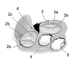
도 1a, 도 1b 및 도 2는 심장 및 그 챔버들의 상이한 시각을 제공한다. 특히, 도 2는 관상 정맥동 (6) 및 삼첨판 (2) 사이의 해부학적 관계를 도시한다. 심장 (1)은 우심방 (RA), 우심실 (RV), 좌심방 (LA) 및 좌심실 (LV)을 포함한다. 우심방 (RA) 및 좌심방 (LA)은 각각 삼첨판 (2) 및 승모판 (3) (총괄하여 방실 판막으로 알려짐)에 의해 우심실 (RV)와 좌심실 (LV)로부터 분리되어 있다. 승모판 (3)은 이첨판라고도 한다. 또한, 폐동맥 (도시되지 않음)은 폐동맥 판막 (5)에 의해 우심실 (LV)로부터 분리되지만, 대동맥 (도시되지 않음)은 대동맥 판막 (4)에 의해 우심실 (RV)으로부터 분리된다. 관상 정맥동 (6) 위치 및 높이의 약간의 변동이 존재할 수 있지만, 관상 정맥동(6)은 일반적으로 후중격 접합면(2d) 위의 삼첨판(2)의 중간 및 상부이다. 관상 정맥동(6)은 심장 근육 (심근)에서 산소가 제거된 혈액을 수집하여 이를 우심방 (RA)으로 전달하는 큰 혈관을 형성하기 위해 함께 결합된 정맥의 집합이다.1A, 1B and 2 provide different views of the heart and its chambers. In particular, FIG. 2 shows the anatomical relationship between the
본래 방실 판막은 각각의 오리피스(orifice)를 가로 질러 안쪽 고리로부터 서로를 향해 연장하는 유연한 첨판을 포함한다. 첨판은 혈액흐름을 따라 함께 만나거나 "접합"하여 한 방향 유체 폐색 표면을 형성한다. 첨판은 예를 들어 후중격 접합면(postero commissure)(2d)과 같은 접합면들에서 서로 만난다. 삼첨판 (2)은 전위 첨판(2a), 후 첨판 (2b) 및 중격 첨판 (2c)을 포함하며, 승모판 (3)은 전위 첨판 (3a) 및 후 첨판 (3b)을 포함한다. 심장 (1)은 또한 심실 내에서 탯줄 같은 힘줄이고 유두근을 삼첨판 및 승모판 첨판에 연결시키는 건삭(chordae tendineae) (도시 생략)을 포함한다. 건삭은 긴장이 되어 첨판을 당겨 폐쇄된 위치에 유지시킴으로써 특히 수축기 동안 첨판의 외반 및 탈출을 방지한다.Native atrioventricular valves contain flexible leaflets extending towards each other from the inner annulus across each orifice. The leaflets meet or "bond" together along the bloodstream to form a unidirectional fluid occlusive surface. The leaflets meet each other at junctions, such as, for example,
우심방 (RA)은 정맥 시스템으로부터 상대 정맥(8) 및 하대 정맥(9)를 통해 산소가 제거된 혈액을 받는 반면, 좌심방 (LA)은 폐에서 정맥을 통해 산소가 공급된 혈액을 받는다. 심실 확장기 동안 심방의 혈액은 심방 근육의 수축 및 심실 근육의 확장 (이완)에 의해 삼첨판 (2) 및 승모판 (3)을 통해 심실로 펌핑된다. 심실 수축 과정에서 우심실 (RV)은 수축하여 폐동맥을 통해 폐로 혈액을 펌프하는 반면 좌심실 LV는 수축하여 대동맥을 통해 신체의 나머지 부위로 혈액을 공급한다. 심실 수축 과정에서 삼첨판 (2) 및 승모판 (3)의 첨판이 닫혀 혈액이 심실에서 심방으로 역류하는 것을 방지한다.The right atrium (RA) receives deoxygenated blood from the venous system via the superior vena cava (8) and inferior vena cava (9), while the left atrium (LA) receives venous oxygenated blood from the lungs. During ventricular diastole, blood from the atria is pumped into the ventricles through the tricuspid valve (2) and mitral valve (3) by contraction (relaxation) of the ventricular muscle and contraction of the atrial muscle. During ventricular contraction, the right ventricle (RV) contracts and pumps blood through the pulmonary artery to the lungs while the left ventricle LV contracts and supplies blood to the rest of the body via the aorta. During ventricular contraction, the cusps of the tricuspid (2) and mitral (3) valves close to prevent backflow of blood from the ventricles into the atria.
본 발명은 심장 판막의 기능을 향상시키기 위해 심장 판막 회복 장치 및 인플란트하는 방법에 관한 대표적인 실시예를 제공한다. 명세서 전반에 걸쳐 심장 판막에는 천연 및 성형/인공 심장 판막이 포함된다. 따라서, 본 발명의 심장 판막 회복 장치는 천연 및 성형/인공 심장 판막을 치료 및/또는 회복하도록 적용된다. 또한, 심장 판막은 삼첨판, 승모판, 폐동맥 판막 및 대동맥 판막을 포함한다.The present invention provides representative embodiments of a heart valve restoration device and a method for implanting in order to improve the function of a heart valve. Throughout the specification heart valves include natural and plastic/artificial heart valves. Accordingly, the heart valve repair device of the present invention is adapted to treat and/or repair natural and cosmetic/artificial heart valves. Heart valves also include tricuspid valves, mitral valves, pulmonary valves, and aortic valves.
개시된 장치의 개별 구성 요소들은 상호 배타적이거나 달리 물리적으로 불가능하지 않으면 결합될 수 있다. 고정 수단, 연결 수단 및 접합 구조물의 다양한 실시예가 본 명세서에 개시되어 있으며, 이러한 요소들의 임의의 조합은 구체적으로 배제되지 않는 한 제조될 수 있다. 예를 들어, 접합 구조물 중 어떤 것이든 명시적으로 개시되지 않더라도 스텐트 및 클램프를 포함하되 이에 국한되지 않는 모든 고정 수단과 결합될 수 있다. 마찬가지로, 접합 구조물의 서로 다른 구조는 명시적으로 개시되지 않더라도 모든 조직 덮개를 유연한 프레임과 결합하는 것과 같이 혼합, 일치 및/또는 결합될 수 있다.Individual components of the disclosed apparatus may be combined unless otherwise mutually exclusive or otherwise physically impossible. Various embodiments of fastening means, connecting means and bonding structures are disclosed herein, and any combination of these elements may be manufactured unless specifically excluded. For example, any of the bonding structures may be combined with any fixation means including, but not limited to, stents and clamps, even if not explicitly disclosed. Likewise, different structures of bonding constructs may be mixed, matched and/or combined, such as joining all tissue sheaths with a flexible frame, even if not explicitly disclosed.
본 발명은 심장 판막 회복 장치를 사용하여 심장 판막 역류를 치료하는 방법에 관한 것이며, 심장 판막 회복 장치는 병든 및/또는 고장난 심장 판막, 또는 고장난 인공 심장 판막을 가로 지르는 혈액 흐름의 역류를 방지, 감소 및/또는 최소화하는 것을 목적으로 한다. 본 발명은 또한 심장 판막 회복 장치를 임플란트하는 방법에 관한 것이다. 또한, 본 발명은 삼첨판을 회복 또는 교체하는 새로운 방법에 관한 것이다. 또한, 본 발명은 또한 이러한 장치를 전달 및 제조하는 방법에 관한 것이다.The present invention relates to a method for treating heart valve regurgitation using a heart valve repair device, wherein the heart valve repair device prevents, reduces, or reduces the backflow of blood flow across a diseased and/or malfunctioning heart valve, or a malfunctioning prosthetic heart valve. and/or to minimize. The present invention also relates to a method of implanting a heart valve repair device. The present invention also relates to a novel method for repairing or replacing the tricuspid valve. The invention also relates to a method of delivering and manufacturing such a device.
본 발명은 최소 침습적 또는 트랜스카테터 임플란트가 가능한 심장 판막 회복 장치를 사용하여 질병이 있는 심장 판막 또는 고장난 인공 심장 판막의 회복 또는 치료에 관한 것이다. 본 발명은 최소 침습적 접근법을 사용하여 심장 판막 역류를 치료하는 방법 및 질환이 있는 및/또는 고장난 판막 또는 고장난 인공 판막을 가로 지르는 혈류의 역류를 방지, 감소 및/또는 최소화하는 것을 목표로 하는 장치에 관한 것이다. 천연 판막은 판막 주변의 환상 확장, 심실 확장 또는 편평한 첨판을 야기하는 이완된 판막 첨판을 포함하지만 이에 제한되지 않는 몇 가지 이유로 인해 적절히 닫힐 수 있는 능력을 상실할 수 있다. 질병 (예: 류마티스 질환)은 판막 첨판 수축을 일으켜 판막 첨판 사이의 판막에 간극을 남길 수 있다. 인공 심장 판막은 예를 들어 마모 및 찢김, 피로 및 캐비테이션 등에 의해 고장날 수 있다. 따라서, 역류는 심장 판막이 적절하게 폐쇄될 수 없기 때문에 역으로 (즉, 유출부로부터 유입 부로, 또는 하부에서 상부로) 누출되는 것이다. 심장 판막 역류는 심장의 기능을 심각하게 손상시킬 수 있다. 적절한 순환을 유지하기 위해 더 많은 혈액이 역류 판막을 통해 펌핑되어야 하기 때문이다.FIELD OF THE INVENTION The present invention relates to the recovery or treatment of diseased or broken artificial heart valves using a heart valve repair device capable of minimally invasive or transcatheter implantation. The present invention relates to a method of treating heart valve reflux using a minimally invasive approach and a device aiming to prevent, reduce and/or minimize the reflux of blood flow across a diseased and/or malfunctioning valve or a malfunctioning prosthetic valve. it's about Native valves may lose their ability to close properly for several reasons including, but not limited to, flaccid valve leaflets resulting in annular dilatation, ventricular dilatation, or flat leaflets around the valve. Diseases (eg, rheumatic diseases) can cause valve leaflets to contract, leaving gaps in the valves between the valve leaflets. Prosthetic heart valves can fail, for example, by wear and tear, fatigue and cavitation. Thus, reflux is a leak back (ie, from the outlet to the inlet, or from the bottom to the top) because the heart valve cannot close properly. Heart valve regurgitation can severely impair the functioning of the heart. This is because more blood must be pumped through the reflux valve to maintain proper circulation.
본 발명은 방실 및 반월판, 특히 삼첨판을 치료하고 회복시키기 위한 것이다. 따라서, 우심방 (RA) 및 우심실 (RV)의 해부학적 구조는 본원 명세서에서 보다 상세히 설명될 것이나, 본 발명은 승모판, 폐 동맥 판막 및 대 동맥 판막을 치료하거나 회복시키기 위해 동등하게 사용될 수 있다.The present invention is for the treatment and restoration of atrioventricular and meniscus, in particular tricuspid. Accordingly, while the anatomy of the right atrium (RA) and right ventricle (RV) will be described in greater detail herein, the present invention may equally be used to treat or repair mitral, pulmonary and aortic valves.
심장 판막 회복 장치heart valve recovery device
다양한 실시예에서, 본 발명의 심장 판막 회복 장치는 질환이 있는/고정난 판막 위에 임플란트될 수 있는 적어도 하나의 상부 고정 수단 및 상기 질병 판막의 기능을 회복시키는 수단으로서 질병 판막 환 내에 연장되는 접합 구조물을 포함한다. 상부 고정 수단은 바람직하게는 예를 들어 심방 벽과 같은 질환이 있는/고정난 판막에 대해 상부에 위치한 조직 부위에 고정 (즉, 임플란트)된다.In various embodiments, the heart valve repair device of the present invention comprises at least one upper fixation means that can be implanted over a diseased/fixed valve and a junction structure extending within a diseased valve ring as a means for restoring the function of the diseased valve. includes The upper anchoring means is preferably anchored (ie implanted) to a tissue site located above the diseased/anchored valve, such as for example the atrial wall.
본 발명의 장치의 임플란트는 예를 들어 열린 심장 수술을 통해 행해지지만, 본 발명의 심장 판막 회복 장치는 바람직하게는 예를 들어 정맥 시스템을 통해 심장의 우측에 경피적으로 전달될 수 있는 카테터-전달 장치이다. 경피 전달은 또한 늑간 또는 부복 위의 공간, 또는 내시경 카테터-기반 선행성, 역행성, 또는 트랜스-중격 배치 (예를 들어, 당업계에 공지된 방법)를 통해 수행될 수 있다. 전체 카테터 전달 장치는 다음을 포함할 수 있다:While implantation of the device of the present invention is done, for example, via open heart surgery, the heart valve repair device of the invention is preferably a catheter-delivery device that can be delivered transdermally to the right side of the heart, for example via a venous system. am. Transdermal delivery can also be accomplished via intercostal or supragastric spaces, or endoscopic catheter-based anterior, retrograde, or trans-septal placement (eg, methods known in the art). The overall catheter delivery device may include:
1. 전달 카테터;1. delivery catheter;
2. 고정 수단(상부 고정 수단); 및2. fastening means (upper fastening means); and
3. 질환이 있는/고장난 판막 기능을 회복시킬 목적의 배치가능한 판막 회복(접합) 구조물. 3. A deployable valve repair (joint) structure intended to restore diseased/failed valve function.
상부 고정 수단 및 배치가능한 접합 구조물은 단일 개체 또는 이들의 조합으로서 개별적으로 임플란트되고 배치될 수 있다. 배치 가능한 접합 구조물은 연결 수단을 통해 고정 수단에 부착될 수 있으며, 연결 수단은 테더를 포함하지만 이에 한정되지 않는다. 배치 가능한 접합 구조물 및 상부 고정 수단은 전달 카테터 내에 고정되도록 크림핑/압착될 수 있고, 예를 들면, 관상 정맥동에 고정되는 상부 고정수단과 같은, 폐색 장치에 의해 전달 카테터로부터 목표 위치로 탈출될 수 있다.The upper anchoring means and the deployable bonding structure may be individually implanted and placed as a single entity or a combination thereof. The deployable bonding structure may be attached to the anchoring means via a connecting means, including but not limited to a tether. The deployable abutment structure and upper fixation means may be crimped/pressed to secure within the delivery catheter and prolapsed from the delivery catheter to the target location by an occlusion device, such as, for example, an upper fixation means secured to the coronary sinus. there is.
상부 고정 수단은 스텐트, 클램프, 후크, 타인(tine), 미늘(barbs), 나사 및 생체 접착제를 포함하지만 이에 한정되지는 않는다. 상부 고정 수단이 예를 들어 클램프 또는 후크인 경우, 상부 고정 수단은 고정을 위해 의도된 조직 부위를 관통할 수 있다. 이러한 상부 고정 수단은 조직(천연 또는 인공/조작된), 금속, 금속 합금, 고분자 또는 다른 인공 재료, 또는 이들의 조합을 포함할 수 있다. 하나 이상의 상부 고정 수단이 본 발명의 장치를 하나 이상의 상부 조직 부위에 고정 및 확보하는데 사용될 수 있다. 2 이상의 상부 고정 수단이 사용되는 경우, 상부 고정 수단의 유형은 서로 다를 수 있다. 바람직하게는, 상기 상부 고정 수단은 스텐트이다. 상부 고정 수단은 바람직하게는 생체 비활성 및/또는 생체 적합성이다.Top fixation means include, but are not limited to, stents, clamps, hooks, tines, barbs, screws, and bioadhesives. If the upper fastening means is, for example, a clamp or a hook, the upper fastening means can penetrate the tissue site intended for fixation. Such upper anchoring means may comprise tissue (natural or artificial/manipulated), metal, metal alloy, polymer or other man-made material, or a combination thereof. One or more upper anchoring means may be used to secure and secure the device of the present invention to one or more upper tissue sites. When two or more upper fixing means are used, the types of the upper fixing means may be different from each other. Preferably, the upper fixation means is a stent. The upper anchoring means is preferably bioinert and/or biocompatible.
본 명에서에 언급된 생체 접합제의 예들로는 에폭시 수지, 에폭시 퍼티, 에틸렌-비닐 아세테이트, 페놀 포름알데히드 수지, 폴리아미드, 폴리에스테르 수지, 폴리프로필렌, 폴리설파이드, 폴리우레탄, 폴리비닐 아세테이트, 폴리비닐 아세테이트, 폴리비닐 알코올 및 폴리 비닐 클로라이드 폴리비닐피롤리돈, 실리콘 및 스티렌 아크릴릭 코 공주합체와 같은 합성 고분자 글루; 아크릴니트릴, 시아노아크릴 레이트, 아크릴 및 레조르시놀 글루와 같은 합성 모노머 글루; 및 폴리스티렌 시멘트/부타논 및 디클로로메탄과 같은 용제형 글루를 포함하나, 이에 한정되지 않는다.Examples of bioconjugates mentioned herein include epoxy resin, epoxy putty, ethylene-vinyl acetate, phenol formaldehyde resin, polyamide, polyester resin, polypropylene, polysulfide, polyurethane, polyvinyl acetate, polyvinyl. synthetic polymer glues such as acetate, polyvinyl alcohol and polyvinyl chloride polyvinylpyrrolidone, silicone and styrene acrylic nose co-copolymer; synthetic monomer glues such as acrylnitrile, cyanoacrylate, acrylic and resorcinol glues; and solvent-based glues such as polystyrene cement/butanone and dichloromethane.
접합 구조물은 풍선, 플랩, 첨판 및 멤브레인을 포함 하지만 이에 한정되지 않는다. 바람직하게는, 접합 구조물은 유연하다. 바람직하게는, 접합 구조물은 네오-첨판(neo-leaflet)이다. 사용시, 접합 구조물은 적어도 하나의 심장 판막 첨판과 접합하고 및/또는 적어도 하나의 심장 판막 첨판들이 접합할 수 있는 표면을 제공한다.Bonding structures include, but are not limited to, balloons, flaps, leaflets, and membranes. Preferably, the bonding structure is flexible. Preferably, the bonding structure is a neo-leaflet. In use, the bonding structure bonds with the at least one heart valve leaflet and/or provides a surface to which the at least one heart valve leaflet can bond.
다양한 실시예에서, 심장 판막 회복 장치는 심실 내 접합 구조물의 말단의 위치를 유지하는 안정화 수단을 포함할 수 있다.In various embodiments, the heart valve repair device may include stabilizing means to maintain the position of the distal end of the junction structure within the ventricle.
다양한 실시예에서, 상기 장치는 심장 판막에 대하여 하부 위치에서 상기 장치를 조직 부위에 고정하도록 구성된 하나 이상의 하부 고정 수단을 포함한다. 하부 고정 수단은 접합 구조물 또는 안정화 수단의 연장일 수 있다. 하부 고정 수단은 클램프, 후크, 타인, 미늘, 나사 및 생체 접착제를 포함 하지만 이에 한정되지 않는다. 하부 고정 수단이 예를 들어 클램프 또는 후크인 경우, 하부 고정 수단은 고정을 위해 의도된 조직 부위를 관통할 수 있다. 이러한 하부 고정 수단은 조직 (천연 또는 인공/조작된), 금속, 금속 합금, 고분자 또는 다른 인공 물질, 또는 이들의 조합을 포함할 수 있다. 하나 이상의 하부 고정 수단은 하나 이상의 하부 조직 위치에 본 발명의 장치를 고정 및 확보하는데 사용될 수 있다. 2 이상의 하부 고정 수단이 사용되는 경우, 하부 고정 수단의 유형은 서로 다를 수 있다. 하부 고정 수단은 바람직하게는 생체 비활성 및/또는 생체 적합성이다.In various embodiments, the device comprises one or more lower anchoring means configured to secure the device to the tissue site in a lower position relative to the heart valve. The lower anchoring means may be an extension of the bonding structure or stabilizing means. Bottom fixing means include, but are not limited to, clamps, hooks, tines, barbs, screws, and bioadhesives. If the lower fixation means are, for example, clamps or hooks, the lower fixation means can penetrate the tissue site intended for fixation. Such an underlying anchoring means may comprise tissue (natural or artificial/manipulated), metal, metal alloy, polymer or other man-made material, or a combination thereof. One or more underlying fixation means may be used to secure and secure the device of the present invention in one or more underlying tissue locations. When two or more lower fixing means are used, the types of the lower fixing means may be different from each other. The lower anchoring means is preferably bioinert and/or biocompatible.
심장 판막 회복 장치는 니티놀-티타늄 튜브로 제조될 수 있으며, 확장 스텐트 구조 및 접합 구조물의 프레임 모두를 포함하는 자체-확장식 임플란트 장치를 달성하기 위해 레이저 절단, 연마 및 열 성형과 같은 공정에 의해 제조될 수 있다. 장치는 또한 전체 또는 부분적으로 조직 (천연 및 인공/조작된 포함)으로 제조 될 수 있다. 바람직하게는, 이러한 조직은 하나 이상의 생리적 기능을 포함하거나 또는 하나 이상의 생리적 기능을 시뮬레이팅할 수 있다.Heart valve repair devices can be fabricated from nitinol-titanium tubes and manufactured by processes such as laser cutting, grinding, and thermoforming to achieve a self-expanding implant device that includes both a frame of an expandable stent structure and a junction structure. can be The device may also be manufactured in whole or in part from tissue (including natural and artificial/manipulated). Preferably, such tissue comprises or is capable of simulating one or more physiological functions.
스텐트stent
스텐트는 조직, 금속, 금속 합금, 고분자 또는 다른 인공 재료, 또는 이들의 조합으로 제조될 수 있다. 바람직하게는, 본 발명의 스텐트는 니티놀-티타늄(nitinol-titanium, 니티놀), Cu-Zn-Al-Ni 합금 및 Cu-Al-Ni 합금을 포함하지만 이에 한정되지 않는 탄성 금속 및/또는 형상 기억을 갖는 금속 합금을 포함한다. 바람직하게는 본 발명의 스텐트는 스텐트가 크림핑/압축되고, 예를 들어 전달 카테터로부터 방출될 때 스텐트가 원래의 비 크림핑/비 압축된 형상으로 되돌아 가게하는 니티놀-티타늄을 포함한다. 니티놀-티타늄은 오스테나이트, 마르텐사이트 및/또는 초 탄성으로 가공될 수 있다. 마르텐사이트 및 초 탄성 금속/금속 합금은 필요한 압축/크림핑 기능을 수행하도록 가공될 수 있다.The stent may be made of tissue, metal, metal alloy, polymer or other artificial material, or a combination thereof. Preferably, the stent of the present invention has an elastic metal and/or shape memory including, but not limited to, nitinol-titanium (nitinol), Cu-Zn-Al-Ni alloy and Cu-Al-Ni alloy. metal alloys having Preferably the stent of the present invention comprises nitinol-titanium, which causes the stent to return to its original un-crimped/uncompressed shape when the stent is crimped/compressed, eg, released from the delivery catheter. Nitinol-titanium can be processed into austenite, martensite and/or superelastic. Martensite and super-elastic metal/metal alloys can be machined to perform the necessary compression/crimp functions.
스텐트에는 레이저 절단 스텐트 또는 땋은(braided) 스텐트가 포함된다. 레이저 절단 스텐트의 제조에서, 레이저는 얇은 등축 금속/금속 합금 튜브에서 규칙적인 절단 아웃을 절단한다. 이어서, 튜브를 원하는 형상의 몰드상에 놓고, 마르텐사이트 온도로 가열하고 급냉시킨다. 이러한 방식으로 스텐트를 처리하면 형상 기억 특성을 가지며 보정된 온도에서 쉽게 기억 모양으로 돌아갈 수 있는 스텐트가 형성된다. 레이저 절단 스텐트는 바람직하게는 니티놀-티타늄으로 제조되지만, 예를 들어 스테인레스 강, 코발트 크롬, 티타늄 및 다른 기능적으로 동등한 금속 및 합금으로 제조될 수도 있다.Stents include laser cut stents or braided stents. In the manufacture of laser cut stents, a laser cuts regular cutouts in a thin equiaxed metal/metal alloy tube. The tube is then placed on a mold of the desired shape, heated to martensite temperature and quenched. Treatment of the stent in this manner results in a stent that has shape memory properties and can easily return to its memory shape at the corrected temperature. The laser cut stent is preferably made of nitinol-titanium, but may be made of, for example, stainless steel, cobalt chromium, titanium and other functionally equivalent metals and alloys.
땋은 스텐트는 브래이딩(braiding) 기술을 사용하여 제조된다. 금속/금속 합금 와이어는 등축 튜브가 와이어로부터 형성될 때까지 오버 및 언더 브래이딩(braiding) 패턴으로 브래이딩 고정 장치/맨드릴에 감겨진다. 스테인레스 강 또는 니티놀-티타늄으로 만들어진 커플링 튜브가 와이어의 느슨한 말단을 연결하는데 사용된다. 느슨한 말단을 커플링 튜브에 넣어 주름지게 한다. 이어서, 땋은 스텐트는 성형 고정 장치 상에 배치되고 스텐트를 특정 온도로 가열하여 스텐트를 원하는 형상으로 설정하고 원하는 마르텐사이트 또는 초 탄성 특성을 발달시킨다.Braided stents are manufactured using braiding techniques. The metal/metal alloy wire is wound around a braiding fixture/mandrel in over and under braiding patterns until an equiaxed tube is formed from the wire. A coupling tube made of stainless steel or nitinol-titanium is used to connect the loose ends of the wire. Crimp the loose end into the coupling tube. The braided stent is then placed on a mold fixture and the stent is heated to a specific temperature to set the stent into the desired shape and develop the desired martensitic or superelastic properties.
본 발명의 스텐트는 상이한 크기들로 이용 가능하게 제조될 수 있다. 스텐트가 고정되는 혈관 (예를 들어, 관상 정맥동)의 크기가 매우 가변적일 수 있으므로, 장치의 다양한 실시예에서 상이한 직경의 스텐트 크기가 제공될 수 있다. 다양한 지름과 길이를 사용할 수 있다. 스텐트는 바람직하게는 압축성/크림핑 가능 및 확장성이므로, 스텐트의 직경 크기는 그것이 고정되는 혈관에 맞게 커스터마이징 및 구성될 수 있으며, 예를 들어, 풍선 카테터가 스텐트를 방사상으로 확장시켜 혈관 조직에 접착 및 고정되도록 하여 스텐트가 조직 부위/혈관에서의 스텐트의 고정 및 안정성을 향상시킬 수 있다. The stents of the present invention may be made available in different sizes. Since the size of the blood vessel (eg, coronary sinus) to which the stent is anchored can be highly variable, stent sizes of different diameters may be provided in various embodiments of the device. Various diameters and lengths are available. As the stent is preferably compressible/crimpable and expandable, the diameter size of the stent can be customized and configured to fit the vessel to which it is anchored, for example, a balloon catheter radially expands the stent to adhere to the vascular tissue. and to be fixed so that the stent can improve fixation and stability of the stent at the tissue site/vessel.
본 발명의 스텐트는 확장 가능한 스텐트일 수 있으며, 상기 확장 가능한 스텐트는 자체 확장 또는 풍선 확장될 수 있다. 바람직하게는, 스텐트는 유연하다.The stent of the present invention may be an expandable stent, and the expandable stent may be self-expanding or balloon-expandable. Preferably, the stent is flexible.
스텐트는 조직 상에 걸리는 외부 표면을 따라 배치된 타인(tins) 및 미늘(barb)을 포함하여 스텐트의 고정 및 안정성을 향상시킬 수 있다.The stent may include tins and barbs placed along an external surface that hangs on the tissue to improve fixation and stability of the stent.
접합 구조물junction structure
다양한 접합 구조물이 본 발명의 심장 판막 회복 장치에 사용될 수 있다. 접합 구조물은 환자의 심장 판막을 가로 질러 연장되도록 형성되고, 심장 판막에 대하여 그의 하부 말단 중 하나의 위치에 위치시키거나 배치한다. 예를 들어, 접합 구조물은 삼첨판을 가로 질러 우심실 내로 연장되도록 배치된다. 접합 구조물은 바람직하게는 실질적으로 심장 판막 환상의 중심을 통해 심실 내로 연장된다. 다양한 실시예에서, 접합 구조물 또는 그의 일부는 판막 접합면, 즉 인접한 판막 첨판 사이를 통해 심실 내로 연장된다.A variety of bonding structures may be used in the heart valve repair device of the present invention. The bonding construct is configured to extend across a heart valve of a patient and locates or disposes at a location at one of its lower extremities relative to the heart valve. For example, the junctional construct is positioned to extend across the tricuspid valve into the right ventricle. The junction structure preferably extends substantially through the center of the heart valve annulus into the ventricle. In various embodiments, the bonding structure, or a portion thereof, extends through the valve bonding surface, ie, between adjacent valve leaflets, into the ventricle.
접합 구조물은 붕괴없이 심장 내압을 견딜 수 있는 충분한 구조적 완전성을 제공하도록 구성된다. 접합 구조물의 형상 및 크기의 선택은 예를 들어 환자의 심장 해부학 및 상태에 의존하는 의사의 선호도에 의존한다. 중요한 것은, 접합 구조물은 판막 기능을 복원함으로써 혈액이 역류 없이 또는 최소한의 역류로 심방에서 심실로 흐르도록 한다.The junction structure is configured to provide sufficient structural integrity to withstand intracardiac pressure without collapse. The selection of the shape and size of the junction structure depends on the preference of the physician, which depends, for example, on the patient's cardiac anatomy and condition. Importantly, the junctional construct restores valvular function, thereby allowing blood to flow from the atrium to the ventricle with no or minimal reflux.
접합 구조물은 풍선, 플랩, 첨판 및 멤브레인을 포함 하지만 이에 한정되지 않는다. 명세서 전반에 걸쳐 접합 구조물이 플랩 또는 첨판인 경우, 본 발명의 접합 구조물은 천연 판막 첨판 및/또는 인공 판막 첨판으로부터 심장 판막 회복 장치는 치료, 수리 및/또는 교체를 목적으로 하는 본 발명의 접합 구조물을 차별화하기 위해 "네오-첨판 (neo-leaflet)"로 지칭될 수 있다. Bonding structures include, but are not limited to, balloons, flaps, leaflets, and membranes. Throughout the specification, when the bonding structure is a flap or leaflet, the bonding structure of the present invention may be used for the purpose of treating, repairing and/or replacing a heart valve recovery device from a native valve leaflet and/or an artificial valve leaflet. may be referred to as “neo-leaflets” to differentiate them.
바람직하게는, 상기 접합 구조물은 유연하다.Preferably, the bonding structure is flexible.
접합 구조물은 조직, 생체 적합성 및/또는 생체-비활성 물질 또는 이들의 조합으로 제조될 수 있다. 조직은 화학적으로 안정화 될 수 있는 생물학적 동물 조직, 예를 들면 소(소) 심낭, 양(양) 심낭, 돼지(돼지) 심낭 또는 말(말) 심낭 및 조작된 조직을 포함하지만 이에 한정되지는 않는다.The bonding construct may be made of a tissue, biocompatible and/or bio-inert material, or a combination thereof. Tissues include, but are not limited to, biological animal tissues that can be chemically stabilized, such as bovine (bovine) pericardium, sheep (sheep) pericardium, porcine (porcine) pericardium or horse (equine) pericardium, and engineered tissues. .
생체 적합성 및/또는 생체-비활성 물질은 금속, 섬유 및 고분자를 포함 하지만 이에 한정되지는 않는다. 생체 적합성 고분자는 폴리우레탄, 폴리에틸렌 테레프탈레이트(PET), 폴리테트라플루오르에틸렌 (PTFE), 폴리에테르에테르케톤 (PEEK), 폴리스티렌-b-폴리 이소부틸렌-b-폴리스티렌 (SIBS), 폴리에스테르, 폴리카보네이트 우레탄, 폴리카보네이트 실리콘, 폴리에테르 우레탄, 분절된 폴리에테르 우레탄, 실리콘 폴리에테르 우레탄, 실리콘, 폴리카보네이트 우레탄, 초고 분자량 폴리에틸렌, 폴리올레핀, 엘라스토머, 나일론, 폴리에틸렌-글리콜, 폴리에테르술폰, 폴리술폰, 폴리비닐피롤리돈, 폴리비닐클로라이드, 다른 플루오로중합체, 실리콘 폴리에스테르, 실록산 중합체 및/또는 올리고머, 폴리락톤 및 블록 공중합체를 포함하지만, 이에 제한되지 않는다.Biocompatible and/or bio-inert materials include, but are not limited to, metals, fibers and polymers. Biocompatible polymers include polyurethane, polyethylene terephthalate (PET), polytetrafluoroethylene (PTFE), polyetheretherketone (PEEK), polystyrene-b-polyisobutylene-b-polystyrene (SIBS), polyester, poly Polycarbonate Urethane, Polycarbonate Silicone, Polyether Urethane, Segmented Polyether Urethane, Silicone Polyether Urethane, Silicone, Polycarbonate Urethane, Ultra High Molecular Weight Polyethylene, Polyolefin, Elastomer, Nylon, Polyethylene-Glycol, Polyethersulfone, Polysulfone, Poly vinylpyrrolidone, polyvinylchloride, other fluoropolymers, silicone polyesters, siloxane polymers and/or oligomers, polylactones and block copolymers.
접합 구조물 또는 그의 일부는 면역 억제제 및 항응고제 (예 : 헤파린)와 같은 첨가제로 처리될 수 있다.The junction construct, or a portion thereof, may be treated with additives such as immunosuppressants and anticoagulants (eg, heparin).
다양한 실시예에서, 접합 구조물은 접합 구조물의 형태, 크기 및 유연성을 유지하는 구조적 지지 프레임을 포함한다. 구조적 지지 프레임은 조직 (천연 또는 인공/조작된) 금속, 금속 합금, 고분자 또는 이들의 조합으로 제조될 수 있다. 바람직하게는 구조적 지지 프레임은 니티놀-티타늄(니티놀), Cu-Zn-Al-Ni 합금 및 Cu-Al-Ni 합금을 포함하지만 이에 한정되지 않는 탄성 금속 및/또는 형상 기억 금속 합금으로 만들어진다. 보다 바람직하게, 구조적 지지 프레임은 니티놀-티타늄으로 제조된다.In various embodiments, the bonding structure includes a structural support frame that maintains the shape, size, and flexibility of the bonding structure. The structural support frame may be made of tissue (natural or artificial/manipulated) metals, metal alloys, polymers, or combinations thereof. Preferably the structural support frame is made of a resilient metal and/or shape memory metal alloy including, but not limited to, nitinol-titanium (nitinol), Cu-Zn-Al-Ni alloys and Cu-Al-Ni alloys. More preferably, the structural support frame is made of nitinol-titanium.
다양한 실시예에서, 접합 구조물은 풍선이며, 풍선의 형상을 제공하는 구조적 지지 프레임 (예를 들어, 구조적 리브를 포함)은 생체 인공 조직 및/또는 생체 적합성 합성 물질에 의해 덮일 수 있다. 상기 풍선은 관 모양, 난형 또는 거의 구형의 형상을 가질 수 둥근 구조의 형태를 가져 지지 폐쇄 요소로서 작용할 수 있고, 회복되는 심장 판막 내에 중심에 위치하여 풍선 주변의 판막 첨판의 접합을 용이하도록 하여 혈액 역류를 방지할 수 있다. 특히 승모판 및 삼첨판의 경우에, 고장난 첨판이 접합하지 않아서 수축기 동안 심실에서 심방으로의 역류를 야기하는 판막에 틈이 생길 수 있다. 폐쇄성 접합 구조물로서의 풍선은 고장 또는 탈출 첨판의 접합을 회복시키는 지지체로서 작용하여, 혈액이 심실에서 우심방으로 역류하는 것을 방지한다. 풍선은 적어도 하나의 심장 판막 첨판의 접합을 위한 표면을 제공한다.In various embodiments, the bonding structure is a balloon, and the structural support frame (eg, including structural ribs) that provides the shape of the balloon may be covered by a bio-artificial tissue and/or a biocompatible synthetic material. The balloon may have a round structure, which may have a tubular, ovoid or nearly spherical shape, may act as a support closure element, and be centrally located within the heart valve to be restored to facilitate bonding of the valve leaflets around the balloon to facilitate blood flow. Backflow can be prevented. Especially in the case of the mitral and tricuspid valves, the failed leaflets can fail to bond, resulting in a gap in the valve causing regurgitation from the ventricle to the atrium during systole. The balloon as an occlusive junctional construct acts as a scaffold to restore junctions of the broken or prolapsed leaflets, preventing backflow of blood from the ventricles into the right atrium. The balloon provides a surface for bonding of at least one heart valve leaflet.
풍선은 다양한 방사상 프로파일을 가질 수 있고, 이러한 형상 프로파일은 풍선의 길이를 따라 변할 수 있으며, 예를 들어 풍선의 일 말단은 원형일 수 있고 다른 말단은 삼각형일 수 있다. 풍선은 다양한 크기 (즉, 방사상 직경) 및 길이를 가질 수 있다. 풍선의 크기 및 길이는 예를 들어, 판막 환형의 크기 및 심장 판막 첨판의 길이에 의존할 수 있다. 상기 풍선은 바람직하게는 상기 판막 첨판들이 서로 접합하기 위한 외부 표면을 제공하도록 형성되고 크기가 정해진 다. 바람직하게는, 풍선의 외부 표면은 연속적이다.The balloon may have a variety of radial profiles, and this shape profile may vary along the length of the balloon, for example, the balloon may be circular at one end and triangular at the other end. Balloons can have various sizes (ie, radial diameters) and lengths. The size and length of the balloon may depend, for example, on the size of the valve annulus and the length of the heart valve leaflets. The balloon is preferably shaped and sized to provide an outer surface for bonding the valve leaflets to each other. Preferably, the outer surface of the balloon is continuous.
다양한 실시예에서, 풍선은 전달시 자체 확장 가능하거나 풍선 카테터와 유사한 방식으로 예를 들면, 외부 액세스 포트를 통해 팽창될 수 있다.In various embodiments, the balloon may be self-expandable upon delivery or may be inflated in a manner similar to a balloon catheter, for example, through an external access port.
다양한 실시예에서, 연결 구조는 네오-첨판이며, 와이어 (또는 복수의 와이어)가 네오-첨판을 위한 구조적 지지 프레임을 형성하도록 형성되고, 생체 인공 물질 및/또는 생체 적합성 물질이 프레임을 덮는다. 이 프레임은 네오-첨판(neo-leaflet)에 유연성을 제공하여 네오-첨판(neo-leaflet)이 정상 심장 판막 첨판과 실질적으로 유사한 방식으로 기능할 수 있다. 네오-첨판은 판막 연결을 회복시키고 첨판 탈출증을 예방하기 위해 고장난 판막 첨판의 연장선 역할을 할 수 있다. 다양한 실시예에서, 네오-첨판은 고유 구조 프레임을 갖는 동물 조직으로부터 형성되어 네오-첨판이 금속, 금속 합금, 고분자 또는 이들의 조합으로 형성된 별도의 구조적 지지 프레임을 필요로 하지 않을 수 있다.In various embodiments, the connecting structure is a neo-leaflet, wherein a wire (or a plurality of wires) is formed to form a structural support frame for the neo-leaflet, and a bio-artificial material and/or a biocompatible material covers the frame. This frame provides flexibility to the neo-leaflet so that the neo-leaflet can function in a manner substantially similar to a normal heart valve leaflet. Neo-leaflets can serve as extensions of failed valve leaflets to restore valve connection and prevent leaflet prolapse. In various embodiments, the neo-leaflets may be formed from animal tissue having an intrinsic structural frame so that the neo-leaflets do not require a separate structural support frame formed of metals, metal alloys, polymers, or combinations thereof.
네오-첨판은 다양한 모양 및 크기, 예를 들어 삼첨판 첨판 또는 그 일부의 형상을 가질 수 있다. 네오 첨판의 모양과 크기는 예를 들어 심장 판막 첨판의 길이에 달려 있다. 또한 네오 첨판(neo-leaflet)은 길이에 따라 두께가 다를 수 있다. 다양한 실시예에서, 네오-첨판 또는 이의 일부는 확장가능하다.Neo-leaflets can have a variety of shapes and sizes, for example, the shape of a tricuspid leaflet or a portion thereof. The shape and size of the neo-cusp depends, for example, on the length of the leaflet of the heart valve. Also, the neo-leaflet may have a different thickness depending on the length. In various embodiments, the neo-leaflets, or portions thereof, are expandable.
다양한 실시예에서, 접합 구조물 또는 그의 일부는 2 개의 심장 판막 첨판 사이의 접합을 통해 판막의 심실쪽으로 임플란트될 수 있으며, 일단 배치되면 환자의 심장 판막 첨판과 함께 일방향 판막으로서 작용하여 혈액의 역류를 방지한다.In various embodiments, the junction structure, or portion thereof, may be implanted into the ventricle of the valve via a junction between the two heart valve leaflets, and once deployed, acts as a one-way valve with the patient's heart valve leaflet to prevent backflow of blood do.
다양한 실시예에서, 접합 구조물은 첨판이 접합할 수 있는 멤브레인 벽 구조로서 작용하여 이들의 탈출 및 혈액 역류를 방지하기 위해 2 개의 판막 첨판 사이의 접합면에 삽입될 수 있다. 이러한 실시예에서, 접합 구조물은 멤브레인이다.In various embodiments, a bonding structure may be inserted into the bonding surface between two valve leaflets to act as a membrane wall structure to which the leaflets may bond to prevent their escape and backflow. In this embodiment, the bonding structure is a membrane.
연결 수단means of connection
다양한 실시예에서, 배치 가능한 접합 구조물 및 상부 고정 수단은 단일한 균일 구조이다. 다른 다양한 실시예에서, 배치 가능한 접합 구조물 및 상부 고정 수단은 별개의 구조이고, 접합 구조물은 하나 이상의 연결 수단에 의해 상부 고정 수단에 부착 가능하고 고정 가능하다. 다양한 실시예에서, 연결 수단은 판막/판막 첨판에 대해 의도된 위치, 예를 들면 심장 판막 중심에 접합 구조물을 배치하도록 구성된다.In various embodiments, the deployable bonding structure and the upper fastening means are of a single uniform structure. In other various embodiments, the deployable bonding structure and the upper securing means are separate structures, and the bonding structure is attachable and fixable to the upper securing means by one or more connecting means. In various embodiments, the connecting means is configured to place the bonding structure at an intended location relative to the valve/valve leaflet, eg at the heart valve center.
연결 수단은 접합 구조물 또는 상부 고정 수단과 일체가 될 수 있다. 연결 수단에는 테더, 나사, 기계식 자물쇠, 후크, 자석, 봉합사 (구경 또는 재질 불문), 섬유, 봉합, 크림프, 스테이플, 리벳, 접착제 및 기타 장치, 임플란트 장치의 다양한 요소를 조립하는데 일반적으로 사용되는 구성 요소 또는 방법이 포함 되지만, 이에 제한되지 않는다. 연결 수단은 바람직하게는 생체 적합성 및/또는 생체 비활성이다.The connecting means may be integral with the bonding structure or the upper fixing means. Connection means include tethers, screws, mechanical locks, hooks, magnets, sutures (regardless of caliber or material), fibers, sutures, crimps, staples, rivets, adhesives and other devices, components commonly used to assemble the various elements of implant devices. elements or methods are included, but are not limited thereto. The connecting means are preferably biocompatible and/or bioinert.
상부 고정 수단이 고정되는 조직 부위 및 치료/회복되는 심장 판막 사이의 거리 및 치료/회복되는 심장 판막의 크기를 설명하기 위해 이용 가능한, 본 발명의 심장 밸브 수선 장치의 구성 요소의 크기 및 형상이 상이할 수 있다는 것을 생각할 수 있다. 따라서, 다양한 실시예에서, 연결 수단은 상부 고정 수단 및 접합 구조물 사이의 거리를 예를 들어 그 길이를 변화시킴으로써 변화시킬 수 있다. 따라서, 연결 수단의 길이는 본 발명의 적용 및 환자 및/또는 의사의 요구 사항에 의존할 것이다. 바람직하게는, 연결 수단은 테더 (로드 및 와이어를 포함)이다. 의사는 연결 수단의 최적 길이를 결정하기 전에 상부 고정 수단 및 접합 구조물 사이의 거리를 측정할 수 있다.The size and shape of the components of the heart valve repair device of the present invention are different, which are available to describe the distance between the tissue site to which the upper fixing means is fixed and the heart valve to be treated/repaired and the size of the heart valve to be treated/repaired. You can think of what you can do. Thus, in various embodiments, the connecting means can vary the distance between the upper fastening means and the bonding structure, for example by changing its length. Accordingly, the length of the connecting means will depend on the application of the present invention and the requirements of the patient and/or physician. Preferably, the connecting means is a tether (including rods and wires). The surgeon may measure the distance between the upper fastening means and the bonding structure before determining the optimal length of the connecting means.
테더는 중합체 (예: PTFE 및 폴리프로필렌), 금속, 금속 합금 (예: 니티놀-티타늄) 및 조직 (천연 또는 인공/조작된)을 포함하되 이에 국한되지 않는 생체 적합성 및/또는 생체 비활성 재료로 제조될 수 있다. 테더는 단일 와이어로 형성되거나 하나 이상의 와이어가 함께 꼬여진 것을 포함할 수 있다. 테더는 비탄성이거나 탄성일 수 있다. 테더는 유연할 수 있으며, 이는 본 발명의 접합 구조물의 유연성에 기여할 수 있다.Tethers are made of biocompatible and/or bioinert materials, including but not limited to polymers (eg PTFE and polypropylene), metals, metal alloys (eg nitinol-titanium), and tissues (natural or artificial/engineered). can be A tether may be formed of a single wire or may include one or more wires twisted together. The tether may be inelastic or elastic. The tether may be flexible, which may contribute to the flexibility of the bonding structure of the present invention.
안정화 수단means of stabilization
다양한 실시예에서, 심장 판막 회복 장치는 심장 판막에 대하여 하부 위치에서 접합 구조물의 말단을 유지하는 안정화 수단을 포함한다. 상기 안정화 수단은 접합 구조물, 상부 고정 수단 또는 연결 수단의 연장일 수 있다. 안정화 수단은 실질적으로 심장 판막을 가로 질러 하부 위치 예를 들면 심심 내로 연장되고 예를 들어 테더(tethers)를 통해 연결 구조의 말단에 연결되어 그 하부 위치를 유지한다. 이러한 테더 (안정화 테더)는 특히 수축기 동안 긴장하여 접합 구조물을 당김으로써 접합 구조물의 탈출을 방지하는 천연 건삭과 비슷한 방식으로 기능한다. 접합 구조물이 네오 첨판(neo-leaflet)인 다양한 실시예에서, 이러한 테더는 긴장이 되어 네오 첨판을 잡아 당김으로써 특히 수축기 동안 네어 첨판의 외반과 탈출을 방지한다.In various embodiments, a heart valve repair device includes stabilizing means for maintaining the distal end of the bonding structure in a lower position relative to the heart valve. The stabilizing means may be an extension of a bonding structure, an upper fixing means or a connecting means. The stabilizing means extends substantially across the heart valve into a lower position, eg, into the heart, and is connected to the distal end of the connecting structure, eg, via tethers, to maintain its inferior position. These tethers (stabilizing tethers) function in a manner similar to natural drywall, which prevents escape of the junction structure by tensioning and pulling the junction structure, especially during systole. In various embodiments where the bonding structure is a neo-leaflet, this tether is tensioned and pulls the neo-leaflet, thereby preventing valgus and prolapse of the neo-leaflet, particularly during systole.
안정화 수단은 금속, 금속 합금, 중합체, 조직 (천연 또는 인공/조작된) 또는 이들의 조합으로 제조될 수 있다. 안정화 수단은 바람직하게는 유연적이고 형상 기억 재료로 제조된다. 바람직하게는, 안정화 수단은 안정화 수단이 작동 중에 그 형상을 유지할 수 있게 하는 충분히 높은 탄성 계수를 갖는 재료로 제조된다. 안정화 수단은 금속, 금속 합금, 중합체 또는 다른 인공 재료, 또는 이들의 조합으로 제조될 수 있다. 바람직하게는, 안정화 수단은 니티놀 티타늄(니티놀), Cu-Zn-Al-Ni 합금 및 Cu-Al-Ni 합금을 포함하지만 이에 제한되지 않는 형상 기억을 갖는 금속 및/또는 금속 합금을 포함한다. 바람직하게는 안정화 수단은 니티놀-티타늄으로 제조된다.The stabilizing means may be made of a metal, metal alloy, polymer, tissue (natural or artificial/engineered) or a combination thereof. The stabilizing means is preferably flexible and made of a shape memory material. Preferably, the stabilizing means is made of a material having a sufficiently high modulus of elasticity to enable the stabilizing means to retain its shape during operation. The stabilizing means may be made of a metal, metal alloy, polymer or other artificial material, or a combination thereof. Preferably, the stabilizing means comprises metals and/or metal alloys with shape memory including, but not limited to, nitinol titanium (nitinol), Cu-Zn-Al-Ni alloys and Cu-Al-Ni alloys. Preferably the stabilizing means is made of nitinol-titanium.
다양한 실시예에서, 상기 안정화 수단은 가중된 말단을 포함한다.In various embodiments, the stabilizing means comprises a weighted end.
다양한 실시예에서, 상기 안정화 수단은 상기 장치를 상기 심장 판막에 대하여 하부 위치에 조직 부위에, 예를 들어 심실쪽 판막에 상기 장치에 고정하기에 적합한 하나 이상의 하부 고정 수단을 포함한다. 안정화 수단은 심장 판막을 가로 질러 접합 구조물을 안정화 시켜, 심장 판막 회복 장치가 심장 주기 및 시간이 경과함에 따라 이동하는 것을 유리하게 방지할 수 있다.In various embodiments, the stabilizing means comprises one or more lower anchoring means suitable for securing the device to the device at a tissue site in a lower position relative to the heart valve, for example to a ventricular valve. The stabilization means may stabilize the junction structure across the heart valve, advantageously preventing the heart valve repair device from migrating over time and throughout the heart cycle.
하부 고정 수단은 클램프, 후크, 타인, 미늘, 나사 및 생체 접착제를 포함 하지만 이에 한정되지 않는다. 하부 고정 수단이 예를 들어 클램프 또는 후크인 경우, 하부 고정 수단은 고정을 위해 의도된 조직 부위를 관통할 수 있다. 이러한 조직 부위는 심내 및 심낭 조직 부위를 포함 하지만 이에 한정되지 않는다.Bottom fixing means include, but are not limited to, clamps, hooks, tines, barbs, screws, and bioadhesives. If the lower fixation means are, for example, clamps or hooks, the lower fixation means can penetrate the tissue site intended for fixation. Such tissue sites include, but are not limited to, intracardiac and pericardial tissue sites.
하부 고정 수단은 안정화 수단과 일체형일 수 있고 조직 (천연 또는 인공/조작된), 금속, 금속 합금, 중합체 또는 다른 인공 재료, 또는 이들의 조합을 포함할 수 있다. 하나 이상의 하부 고정 수단은 하나 이상의 하부 조직 위치에 본 발명의 장치를 고정 및 확보하는데 사용될 수 있다. 2 이상의 하부 고정 수단이 사용되는 경우, 하부 고정 수단의 유형은 서로 다를 수 있다. 하부 고정 수단은 바람직하게는 생체 비활성 및/또는 생체 적합성이다.The lower anchoring means may be integral with the stabilizing means and may comprise tissue (natural or artificial/manipulated), metal, metal alloy, polymer or other artificial material, or a combination thereof. One or more underlying fixation means may be used to secure and secure the device of the present invention in one or more underlying tissue locations. When two or more lower fixing means are used, the types of the lower fixing means may be different from each other. The lower anchoring means is preferably bioinert and/or biocompatible.
심장 판막 회복 장치의 전달, 배치 및 임플란트 방법Methods of delivery, placement and implantation of heart valve recovery devices
본 발명은 본 발명의 심장 판막 회복 장치의 전달, 배치 및 임플란트 방법을 포함한다. 본 발명의 심장 판막 회복 장치의 전달은 단일 또는 다중 단계 공정일 수 있다. 이러한 장치를 전달하는 방법은 최소 침습 접근을 통해 삽입되고 형광 투시 및 초음파 (에코) 유도에 의해 진행된 전달 카테터의 사용을 포함할 수 있다. 조직 부위 (예를 들어, 관상 정맥동) 및 심장 판막 (예: 삼첨판) 간의 3D 관계를 결정하기 위해 심전도 및/또는 CT (전산화 단층 촬영) 및/또는 MRI (자기 공명 영상) 평가가 수술 전에 요구될 수 있다. 관상 정맥동 또는 우심실에 있는 페이싱 리드(pacing lead)를 가진 환자들은 이 치료법에 부적합할 수 있다. 본 발명의 방법은 감염성 심내막염(infective endocarditis) 환자에서는 수행되지 않을 수 있다.The present invention includes methods of delivery, placement and implantation of the heart valve repair device of the present invention. Delivery of the heart valve repair device of the present invention may be a single or multi-step process. Methods of delivering such devices may include the use of a delivery catheter inserted via a minimally invasive approach and advanced by fluoroscopy and ultrasound (echo) guidance. Electrocardiography and/or computed tomography (CT) and/or magnetic resonance imaging (MRI) evaluation may be required prior to surgery to determine the 3D relationship between the tissue site (e.g., coronary sinus) and heart valves (e.g. tricuspid valve) can Patients with pacing leads in the coronary sinus or right ventricle may be unsuitable for this treatment. The method of the present invention may not be performed in patients with infectious endocarditis.
다양한 특정 실시예에서, 전달 방법은 대퇴 정맥, 내부 경정맥 또는 쇄골 하 정맥으로부터의 접근을 사용하여 관상 정맥동에 접근하는 것을 포함할 수 있다. 관상 정맥동의 크기를 결정하기 위해 마커 카테터를 사용할 수 있다. 이는 초음파 심 초음파, 식도경유의 심 초음파, 혈관 초음파와 같은 이미징 기법 또는 조영제 주입을 이용한 형광 투시로 수행할 수 있다. 마커 카테터는 가이드 와이어를 사용하여 전달 시스템과 교환된다.In various specific embodiments, the method of delivery may include accessing the coronary sinus using access from the femoral vein, internal jugular vein, or subclavian vein. A marker catheter may be used to determine the size of the coronary sinus. This can be performed by imaging techniques such as ultrasound echocardiography, transesophageal echocardiography, vascular ultrasound, or fluoroscopy using contrast medium injection. The marker catheter is exchanged with the delivery system using a guide wire.
전달 시스템을 배치하면 스텐트가 관상 정맥동의 구멍에 배치되어 안정성이 검증된다. 안정성 테스트에는 터그 테스트(tug testing)가 포함될 수 있다. 배치가능한 접합 구조물은 예를 들어 우심방 RA에 배치되고 우심실 RV로 유도된다. 이것은 특화된 카테터 또는 전달 카테터의 일부로 수행될 수 있다.Upon placement of the delivery system, a stent is placed into the orifice of the coronary sinus and stability is verified. Stability testing may include tug testing. The deployable junction construct is, for example, placed in the right atrium RA and directed to the right ventricle RV. This may be done as part of a specialized catheter or delivery catheter.
또한, 접합 구조물은 전달 카테터에 의해 다시 완전히 배치되기 전에 우심실 RV에 직접 배치된다. 일단 접합 구조물이 배치되면 심 초음파 및 투시 조영 평가를 수행하여 장치 위치를 확인하고 삼첨판 역류의 적절한 감소를 확인할 수 있다. 이어서 장치의 상부 고정 수단 (예를 들어, 스텐트)이 2 차 단계로서 제 위치에 접합 구조물을 유지하도록 배치된다.In addition, the junction construct is placed directly into the right ventricle RV before being fully placed back by the delivery catheter. Once the zygomatic structures are in place, echocardiography and fluoroscopy evaluations can be performed to confirm device location and to confirm adequate reduction of tricuspid regurgitation. An upper anchoring means of the device (eg, a stent) is then placed to hold the bonding structure in place as a secondary step.
접합 구조물의 배치는 실제 형상과 크기에 달려있다. 펼쳐지거나, 풀린 채로, 풀리지 않은 채로, 펼쳐질 수 있다. 단일 또는 다중 단계 공정으로 배치될 수 있다.The placement of the bonding structure depends on the actual shape and size. It can be unfolded, unfolded, unleashed, and unfolded. It can be deployed as a single or multi-step process.
다양한 실시예들에서, 전달 장치, 예를 들어. 전달 카테터는 본 발명의 심장 판막 회복 장치를 운반하며, 상기 장치는 상부 고정 수단 (예: 스텐트) 및 접합 구조물 (예 : 네오 첨판)을 단일한 균일 구조로 포함한다. 접합 구조물은 먼저 상부 고정 수단에 뒤이어 배치되거나 반대로 배치될 수 있다. 예를 들어, 심장 판막 회복 장치가 삼첨판을 치료/회복하기에 적합한 경우, 상부 고정 수단은 하대 정맥에 고정하도록 작동할 수 있는 스텐트이고, 접합 구조물은 네오 첨판을 포함하고, 상기 네오 첨판은 우심방에 배치될 수 있고 그 다음 부분적으로 우심방으로 빼내고, 그 후 나머지 심장 판막 회복 장치를 하대 정맥으로 끌어 당겨 스텐트가 하대 정맥에 고정된다. 따라서, 심장 판막 회복 장치의 전달 순서는 다음과 같을 수 있다:In various embodiments, a delivery device, eg. The delivery catheter carries the heart valve recovery device of the present invention, wherein the device comprises an upper fixation means (eg, a stent) and a bonding structure (eg, a neo-cusp) in a single uniform structure. The bonding structure may be arranged first after the upper fastening means or vice versa. For example, where the heart valve repair device is suitable for treating/repairing the tricuspid valve, the upper fixation means is a stent operable to anchor the inferior vena cava, and the junctional structure comprises a neo-cusplet, wherein the neo-cusplet is located in the right atrium. It can be placed and then partially withdrawn into the right atrium, after which the remaining heart valve recovery device is drawn into the inferior vena cava and the stent is secured in the inferior vena cava. Accordingly, the delivery sequence of the heart valve recovery device may be as follows:
· 전달 시스템(심장 판막 회복 장치를 포함하는 전달 카테터)은 하대 정맥에서 우심방을 거쳐 삼첨판을 가로질러 우심실로 안내되며;A delivery system (delivery catheter comprising a heart valve restoration device) is guided from the inferior vena cava through the right atrium, across the tricuspid valve and into the right ventricle;
· 접합 구조물로써 네오 첨판의 원위 말단은 우심실로 방출되고 상기 네오 첨판의 근위 부분이 앉거나 위치할 우심방으로 전달 카테터가 끌어 당겨짐에 따라 펼쳐지며; 그리고The distal end of the neo-cusp as a junctional construct is ejected into the right ventricle and unfolds as the delivery catheter is drawn into the right atrium where the proximal portion of the neo-cusp will sit or be located; And
· 상기 카테터를 하대 정맥으로 더 끌어 당겨 상부 고정 수단으로써의 스텐트가 스텐트에 부착된 네오 첨판과 배치되고 상기 네오 첨판은 연결 수단(예, 생체 접착제, 바늘, 후크 및 테더)에 의해 스텐트와 일체화되거나 스텐트에 부착될 수 있다.Drawing the catheter further into the inferior vena cava so that the stent as an upper fixation means is placed with a neo-cusplet attached to the stent and the neo-cusplet is integrated with the stent by a connecting means (e.g., bioadhesive, needle, hook and tether) or It can be attached to a stent.
다양한 실시예에서, 심장 판막 회복 장치의 전달, 배치 및 임플란트는, 예를 들어, 상부 고정 수단인, 예를 들어, 스텐트가 먼저 접합 구조물 전에 관상 정맥동 또는 하대 정맥에 전달되어 고정되고, 예를 들면 네오 첨판이 상부 고정 수단에 전달되어 고정되고 삼첨판 판에 배치되는 다단계 공정을 포함한다.In various embodiments, delivery, placement, and implantation of a heart valve repair device is achieved by first delivering and securing the coronary sinus or inferior vena cava prior to the junction construct, e.g., an upper fixation means, e.g., a stent, e.g. It comprises a multi-step process in which the neo-leaflets are transferred to and secured to an upper holding means and placed on a tri-leaflet plate.
일 양태에서, 본 발명은 상부 고정 수단을 심장 판막 부근에 심장 챔버의 고정 위치 (바람직하게는 혈관 입구)로 전진시키고 및 상부 고정 수단을 그 위치에 배치하는 단계, 및 배치가능한 접합 구조물 (예: 네오-첨판)를 배치하고 판막 기능을 회복시키기 위한 접합 구조물의 기능을 보장하는 단계를 포함하는 최소 침습적 접근으로 심장 판막을 치료 도는 회복시키는 방법에 관한 것이다. 상기 절차는 판막을 가로 질러 접합 구조물의 원위 부분을 통과시키기 위해 추가 카테터를 전진시키는 단계를 포함할 수 있다. 이들 단계는 다른 역순으로 수행될 수 있음을 이해할 것이다.In one aspect, the present invention provides a method comprising the steps of advancing an upper anchoring means to a fixed position of a heart chamber (preferably a vascular entrance) proximate a heart valve and disposing the upper anchoring means in that position, and a deployable bonding structure (eg: A method of treating or restoring a heart valve with a minimally invasive approach comprising placing a neo-leaflet) and ensuring the function of a bonding construct to restore valve function. The procedure may include advancing an additional catheter to pass the distal portion of the bonding structure across the valve. It will be appreciated that these steps may be performed in any other reverse order.
삼첨판 회복의 특정 실시예에서, 본 발명은 본 발명의 심장 판막 회복 장치를 전달 및 임플란트하는 방법에 관한 것으로서, 상기 방법은 관상 정맥동에 카테터를 삽입하고 상부 고정 수단을 전달하는 단계, 및 삼첨판을 가로 질러 접합 구조물 (예: 네오-첨판)을 배치시키는 단계를 포함하여 판막 기능을 복원시킨다. 상술한 단계들 각각은 상이한 순서로 수행할 수 있음을 이해할 것이다.In a particular embodiment of tricuspid restoration, the present invention relates to a method of delivering and implanting a cardiac valve restoration device of the present invention, the method comprising the steps of inserting a catheter into the coronary sinus and delivering an upper fixation means, and transversing the tricuspid valve. Restoring valve function, including placing a junction structure (eg, neo-leaflet) across the wall. It will be appreciated that each of the steps described above may be performed in a different order.
승모판 회복의 특정 실시예에서, 본 발명은 본 발명의 심장 판막 회복 장치를 전달 및 임플란트하는 방법에 관한 것으로, 상기 방법은 폐 정맥 중 하나에 카테터를 삽입하고 상부 고정 수단을 전달하는 단계, 및 승모판을 가로 질러 접합 구조물 (예: 네오 첨판)을 배치시키는 단계를 포함하여 판막 기능을 복원시킨다. 상술한 단계들 각각은 상이한 순서로 수행할 수 있음을 이해할 것이다.In a particular embodiment of mitral valve restoration, the present invention relates to a method of delivering and implanting a heart valve restoration device of the present invention, the method comprising: inserting a catheter into one of the pulmonary veins and delivering an upper anchoring means; Restoring valve function, including placing a bonding structure (eg, neo-cusplets) across the It will be appreciated that each of the steps described above may be performed in a different order.
삼첨판 및 승모판 회복 모두에서 심장 판막 회복 장치의 전달은 대퇴 정맥, 내부 경정맥 또는 쇄골 하 정맥 및 트랜스중격 천자를 통해 좌우 심방에서 진행될 수 있다.Delivery of cardiac valve restoration devices in both tricuspid and mitral valve restoration can proceed in the left and right atrium via femoral vein, internal jugular vein or subclavian vein and transseptal puncture.
삼첨판 및 승모판 회복의 특별한 경우가 설명되지만, 본 발명의 원리에 따른 장치는 대동맥 판막 또는 폐동맥 판막의 역류를 교정하는데 사용될 수 있음이 이해된다.Although the particular case of tricuspid and mitral valve repair is described, it is understood that a device according to the principles of the present invention may be used to correct regurgitation of an aortic valve or a pulmonary valve.
다양한 실시예에서, 심장 회복 장치의 각 구성 요소는 전달 카테터 시스템을 통해 환자로부터 회수 및 제거 가능하다.In various embodiments, each component of the cardiac recovery device is retractable and removable from the patient via a delivery catheter system.
본 발명의 of the present invention 실시예Example
심장 판막 회복 장치heart valve recovery device
도 1 및 도 2는 축 방향 (도 1a 및 도 1b) 및 관상도 (도 2)에서 상이한 판막 위치 사이의 해부학적 관계를 나타내는 심장(1)의 개략도이다. 관상 정맥동(6)과 폐동맥(7)의 구멍의 위치는 각각 삼첨판 (2) 및 승모판 (3) 위에서 볼 수 있다. 도 2에서, 상대 정맥 (8)으로부터 관상 정맥동 (6) 내로 전진된 가이드와이어 (50)가 도시되어 있다. 심장 최소 침습 절차 동안, 가이드와이어 (50)는 종종 심장 카테터 삽입 중에 사용되어 액세스 포인트로부터 원하는 위치로의 가이드 경로를 얻고 그 특정 원하는 위치에 가이드 카테터 껍질 및 다른 카테터를 전진시킬 수 있다. 이러한 와이어 또는 가이드 카테터는 본 발명의 심장 판막 회복 장치를 관상 정맥동 (6) 내로 전진시키고 전달하기 위해 본 발명에서 사용될 수 있다.1 and 2 are schematic diagrams of a
도 3 내지 도 5, 도 14 및 도 15는 본 발명의 심장 판막 회복 장치 (10)의 실시예를 제공한다. 도 3은 본 발명의 일 실시예에 따른 심장 판막 회복 장치 (10)를 구비한 우심실 (RV) 및 삼첨판 (2)을 나타내는 도 2에 도시된 해부학적 구조의 개략적인 확대도를 도시한다. 심장 판막 회복 장치 (10)는 상부 고정 수단으로서의 스텐트 (11) 및 배치가능한 접합 구조물로서의 네오-첨판(12)를 포함한다. 네오-첨판(12)은 스텐트 (11)의 한쪽 말단에 위치한 경계(11a)에서 스텐트 (11)로부터 연장한다. 바람직하게는, 네오 첨판(12)은 스텐트 (11)의 하부 경계(11a)로부터 연장하여 상기 장치(10)가 환자 심장의 올바른 방향으로 임플란트될 때, 상기 네오-첨판(12)이 본 명세서에 기술 된 바와 같이 기능하도록 상기 네오 첨판은 심장 판막에 근접하여 위치된다. 하부 경계 (11a)는 스텐트 (11)가 예를 들어 관상 정맥동(6)에 올바른 방향으로 임플란트될 때 스텐트 (11)의 말단의 하부인 것으로 이해될 것이다 (도 5c). 다양한 실시예에서, 하부 경계 (11a)는 스텐트 (11)가 올바른 방향으로 임플란트될 때 스텐트 (11)의 말단의 최하부 끝이다. 적용 및 요구 사항에 따라, (접합 구조물로서) 네오-첨판(12)은 내부 루멘 면, 외부 루멘 면 및 스텐트(11)의 길이에 따른 어디든지 예를 들면 스텐트(11)의 말단 및 내측부를 포함하지만, 이에 제한되지 않는 (상부 고정 수단으로서의) 스텐트 (11)의 하나 이상의 부분에 부착 가능하다. 바람직하게는, 네오-첨판(12)은 (예를 들어 바늘, 후크 및/또는 나사를 통해) 내부 경계, 표면, 루멘 및/또는 스텐트(11)의 부분에 부착될 수 있다.3-5, 14 and 15 provide an embodiment of a heart
스텐트(11) 및 네오-첨판(12)은 단일 구조를 형성하며, 스텐트 (11)의 재료는 네오-첨판 (12)의 일부를 형성하는데 사용된다. 도 14를 참조하면, 스텐트 (11)는 네오-첨판(12)의 첨판/플랩 형상을 형성하는 구조적 지지 프레임 (12a)을 형성하도록 연장되는 부분을 포함하는 금속 합금, 바람직하게는 니티놀-티타늄(nitinol-titanium)으로 제조된다. 구조적 지지 프레임은 도 5a에 도시된 바와 같이 곡면 프로파일을 갖는 네오-첨판(12)을 제공한다. 생체 인공 재료 (12b)는 예를 들어, 바늘, 후크 및/또는 나사에 의해 구조적 지지 프레임 (12a)에 부착되어 네오-첨판(12)을 완성한다. 상기 구조적 지지 프레임(12a)은 장치 (10)의 작동 중에 네오-첨판(12)을 고정시키고 네오 첨판(12)에 요구되는 강성을 제공하여 네오 첨판(12)의 원위 말단 부분의 탈출을 방지한다. 구조적 지지 프레임 (12a)은 또한 네오-첨판(12)에 요구되는 유연성을 제공하여 작동 중에 심장 판막 첨판과의 접합을 위한 정상 판막 첨판과 실질적으로 유사한 방식으로 기능하도록 한다. 다양한 실시예에서, 네오-첨판(12)은 중격 첨판(2c)의 중간 부분에 실질적으로 대응하는 형상을 포함한다.The
다양한 실시예에서, 스텐트 (11) 및 네오-첨판(12)는 별개의 구성 요소이고 네오-첨판(12)은 본 명세서에 개시된 수단 및 방법, 예를 들어 바늘, 생체 접착제, 후크 및/또는 나사를 통해 경계(11a)의 스텐트(11)에 부착가능하다.In various embodiments, the
스텐트 (11)는 관상 정맥동 (6)에 임플란트 가능하며, 경계 (11a)는 바람직하게는 관상 정맥동 (6)의 구멍(6a)에 실질적으로 위치된다. 스텐트 (11)는 크림핑/압착될 수 있고 카테터는 관상 정맥동(6)에서 확장 및 이식되기 전에 관상 정맥동(6)에 전달된다. 관상 정맥동(6)에서 스텐트 (11)의 안정성은 터그 테스트를 통해 테스트될 수 있다. 네오-첨판 (12)은 바람직하게는 삼첨판 (2)의 실질적으로 중심 위치 (제 1 위치)를 통해 삼첨판(2)을 가로 질러 우심실 (RV)으로 배치되어 연장된다. 네오-첨판은(12)은 삼첨판(2)을 가로 질러 연장하여 우심실 (RV) 내의 네오-첨판(12)의 자유 말단(12')을 삼첨판 (2)의 하부에 위치시킨다. 자유 말단(12')은 작동시, 즉 심장 수축기 및 이완기 동안 모두 삼첨판(2)의 하부에 위치시키는 것이 바람직하다. 자유 말단(12')은 스텐트 (11)로부터 말단이다. 자유 말단(12')은 심장주기 동안 실질적으로 제한되지 않고 움직일 수 있지만, 심장 판막으로부터 하부에 남아있다. 다양한 실시예에서, 자유 말단(12')은 조직 부위에 고정되지 않는다. 심장 판막이 기능을 상실하고 역류가 있는 경우, 판막의 첨판은 일반적으로 완전히 접합되지 않고 판막이 닫히지 않아 혈액이 판막의 영역을 통해 심방으로 역류하여 심장 박동 메커니즘에 영향을 준다. 네오-첨판(12)은 우심실 (RV)의 혈액이 폐동맥 판막 (5)을 통해 방출되도록 심실 수축기 동안 폐쇄되는 삼첨판 (2) 기능을 회복시키는 메커니즘으로서 작용한다. 도 3, 4 및 15에 도시된 바와 같이, 네오-첨판(12)은 본래의 판막 첨판 중 적어도 하나에 연장되어, 접합을 위해 이용 가능한 길이를 증가시킨다. 따라서, 작동시, 네오-첨판 (12)은 심실 수축기 동안 전위 첨판(2a) 및 후위 첨판(2b)을 협착하여 혈액의 역류를 방지, 감소 및/또는 최소화하는 중격 첨판(2c)의 연장 및 이와 같은 기능을 한다. 바람직하게는, 네오-첨판(12)은 실질적으로 중간 첨판(2c)으로 연장된다. 다양한 실시예에서, 네오-첨판 (12)의 부분은 예를 들어 판막 첨판 사이의 접합면, 예를 들면 (2d), 후위 첨판(2b) 및 중간 첨판(2c) 사이의 접합면(2d)을 통해 다른 위치에서 우심실 (RV)로 연장한다.The
심장 판막 회복 장치 (10)는 당업계에 공지된 최소 침습 수단을 통해 효율적으로 임플란트될 수 있기 때문에 유리하다. 스텐트 (11)는 혈관인 상부 조직 부위에 용이하게 고정될 수 있고, 네오-첨판(12)은 고장난 판막을 가로 질러 연장되어 다른 판막 첨판과 접합함으로써 신속하게 판막 기능을 회복시킨다.The heart
도 6은 스텐트(111) 및 연결 테더 (연결 와이어) (113)를 통해 스텐트 (111)에 부착되는 네오-첨판(112)을 포함하는 심장 판막 회복 장치 (110)의 다른 실시예를 제공한다. 네오-첨판(112)은 꽃잎/패들 형상의 플랩이다. 장치 (110)의 작동 중에, 테더 (113)는 배치가능한 네오-첨판(112)을 심장 판막 내의 의도된 위치 (예를 들어, 판막 첨판들 사이의 중심)로 연장시키고, 의도된 의치에 네오-첨판(112)의 방향 및 위치를 정렬하고 실질적으로 유지한다. 의도된 위치(들)에서 네오-첨판(112)의 위치는 판막 첨판들 및 네오-첨판(112) 사이의 최대 접합을 보장함으로써 심장 판막의 회복/치료에서 장치 (110)의 효율을 최적화한다. 그러므로 상기 테더(113)는 형상 기억 합금, 예를 들면 니티놀-티타늄으로 만들어져 의도된 위치(들)에서 네오-첨판(112)의 위치를 효과적으로 유지할 수 있도록 한다.6 provides another embodiment of a heart
도 6에서, 스텐트 (111), 네오-첨판(112) 및 테더 (113)는 하나의 단일 구조이고, 여기서 테더 (113)는 스텐트 (111)에서 네오-첨판(112)으로 연장되어 네오-첨판(112)의 형상 및 구조를 형성한다. 그러나, 다른 실시예에서, 스텐트 (111) 및 네오-첨판(112)은 테더 (113)를 통해 서로 부착 가능한 별도의 구성 요소이다. 부착 지점은 테더 (113)의 양 말단 또는 양 말단 중 하나(즉, 경계 (111a) 및/또는 네오 첨판(112)), 또는 테더 (113)의 중간 부분에 위치할 수 있다.In FIG. 6 , the
테더 (113)는 바람직하게는 유연하여, 작동 중에 심장 판막 회복 장치 (110)에 추가적인 유연성을 제공한다. 테더 (113)의 길이는 본 발명의 적용 및 환자 및/또는 의사의 필요에 의존한다. 예를 들어, 상기 테더 (113)는 환자의 삼첨판(2)에 대한 관상 정맥동의 구멍 (ousium)(6a)의 거리에 실질적으로 대응하는 길이를 포함할 수 있다. 작동 중에 테더 (113)의 길이의 실질적인 변화를 피하기 위해, 테더 (113)는 바람직하게는 비탄성이다.The
도 7은 관상 정맥동(6)으로 임플람트된 스텐트(211), 테더(213) 및 삼첨판 첨판 사이의 중심 위치를 통해 삼첨판(2)을 가로 질러 우심실 (RV) 내로 연장하는 접합 구조물(212)을 포함하는 심장 판막 회복 장치(210)의 다른 일 실시예를 제공한다. 작동 중 (즉, 수축기 및 이완기 동안), 접합 구조물(212)은 삼첨판(2)을 가로 질러 연장되어 우심실 (RV)에서 삼첨판(2)의 하부에 접합 구조물(212)의 자유 말단(212')을 위치시킨다. 접합 구조물 (212)은 작동시 구조 지지 프레임 (212a) 및 적어도 하나의 판막 첨판과의 접합을 위한 표면을 갖는 확장 가능 부분(214)을 포함하여 혈액의 역류를 방지, 감소 및/또는 최소화하는 풍선(212)이다.7 shows a
확장 가능 부분 (214)은 자체 확장가능하거나 풍선 카테터를 통해 확장될 수 있다. 작동시, 확장 가능 부분 (214)은 테더 (213)를 통해 판막(2) 내에 위치하여 확장 가능 부분 (214) 또는 그 일부가 판막 첨판의 접합을 위한 지지를 제공하도록 한다. 따라서, 확장 가능 부분 (214)은 판막 첨판 사이에서 심실 내로 충분히 연장되는 길이를 포함하여, 판막 첨판의 접합을 위한 지지를 제공한다. 이러한 길이는 예를 들어, 상부 조직 고정 부위 및 판막 사이의 거리 및/또는 심장 판막 첨판의 길이에 의존할 수 있다. 심장 판막 첨판의 길이는 종종 불일치하므로, 확장 가능 부분 (214) (또는 네오 첨판)의 길이를 결정할 때 심장 판 막 첨판의 상이한 길이가 고려되어야 한다는 것을 알 수 있을 것이다. 따라서, 확장 가능 부분 (214)는 구조적 지지 프레임 (212a) 또는 그 일부의 전체 길이 (즉, 말단까지)를 연장할 수 있다.The
다른 실시예에서, 접합 구조물 (212)은 확장 가능한 네오-첨판(212)이며, 네오-첨판(212)의 일부, 예를 들면 생체 인공 조직을 포함하는 부분은 확장 가능하다.In another embodiment, the
도 8은 심장의 좌심방 (LA)에서 승모판 (3) 위에 임플란트된 도 5의 심장 판막 회복 장치 (10)를 도시한다. 장치 (10)의 스텐트 (11)는 폐 정맥 (7)으로 임플란트되고 네오-첨판 (12)은 스텐트 (11)로부터 승모판을 가로 질러 좌심실(LV)로 연장된다. 네오-첨판(12)은 바람직하게는 적어도 하나의 승모판 첨판, 및 승모판 첨판 사이로 연장된다. 다양한 실시예에서, 장치 (10)는 좌심방 (LA)의 하나 이상의 폐 정맥 (7)에 임플란트될 수 있는 하나 이상의 상부 고정 수단, 즉 하나 이상의 스텐트 (11)를 포함한다. 장치 (10)는 삼첨판에 대해 도 3 내지 도 5, 도 14 및 도 15와 관련하여 상술한 것과 동일한 방식으로 기능한다.FIG. 8 shows the heart
도 9a 및 9b는 심장 판막 회복 장치 (310)의 또 다른 실시예로서 관상 정맥동(6)에 임플란트된 스텐트 (311) 및 접합 구조물 (312)을 포함한다. 접합 구조물(312)은 우심실(RV) 내 후중격 접합면(2d)에 인접한 판막 첨판들, 예를 들면 후위 첨판(2b) 및 중간 첨판(2c) 사이로 연장가능한 멤브레인(312)이며, 상기 멤브레인(312)의 자유 말단 (312')은 우심실 (RV)에서 삼첨판 (2)의 하부에 위치한다. 멤브레인 (312)은 판막 첨판(2b, 2c)의 접합을 향상시키는 중격으로서 기능한다. 멤브레인 (312)은 바람직하게는 접합면(2d)을 통해 삼첨판 (2)을 가로 질러 연장되어 첨판들이 접합하여 멤브레인 벽 구조체로서 작용함으로써 혈액의 탈출 및 역류를 방지할 수 있다.9A and 9B are another embodiment of a heart valve repair device 310 including a
도 10a 및 도 10b는 관상 정맥동 (6), 테더 (413), 역류 배리어 (412) 및 다리 (415) (제 2 상부 고정 수단)에 임플란트된 스텐트 (411)를 포함하는 심장 판막 회복 장치 (410)의 다른 실시예를 제공한다. 다리 (415)는 우심방 (RA)의 반대측, 즉 관상 정맥동 (6)의 반대측으로 연장된다. 역류 배리어 (412)는 역류 영역의 위 및 중심(예를 들면, 판막 첨판들 사이 및 상부에)에 테더 (413) 및 다리 (415)에 의해 배치되어 심장 주기 동안 고장난 판막에서 혈액의 역류를 방지한다. 다리 (415)는 고정난 판막 첨판의 탈출을 방지함으로써 회복 구조체로서 작용하는 역류 배리어 (412)의 안정성을 유지한다.10A and 10B show a heart
다양한 실시예에서, 역류 배리어 (412)는 작동시 판막 첨판과 접합하지 않지만, 본 발명의 네오-첨판 (예 : 네오-첨판(12))과 실질적으로 동일한 구조를 갖는다. 이러한 실시예에서, 역류 배리어 (412)는 첨판 또는 플랩과 같은 형상을 갖는 유연한 구조 지지 프레임, 및 프레임에 부착된 생체 인공 조직을 포함한다. 역류 배리어 (412)는 바람직하게는 유연하다. 바람직하게는, 역류 배리어 (412)는 실질적으로 평면이다.In various embodiments, the
다리 (415)는 적용 및 요구 사항에 따라 테더(413) 또는역류 배리어 (412)의 말단 (스텐트 (411)로부터 말단)으로부터 연장될 수 있다. 다리(415)는 장치 (410)의 단일 구조의 일부이거나 장치 (410)에 부착 가능한 별도의 구성 요소의 일부일 수 있다. 다리(415)의 말단은 심방의 벽과 결합/접하도록 형상화되어,저항력을 제공하여 장치(410) 및 삼첨판(2)과 관련된 역류 배리어(412)의 위치를 유지한다. 다양한 실시예에서, 다리(415)의 말단은 심방의 벽에 고정되도록 구성되고, 예를 들어 다리(415)의 말단은 심방 벽을 관통하기에 적합한 클램프를 포함하여 심방에 장치를 고정한다. 다리 (415)는 스텐트 (411), 테더 (413) 및/또는 역류 배리어(412)의 구조적 지지 프레임과 동일한 재료로 제조될 수 있다. 다양한 실시예에서, 장치 (410)는 단일 다리(415) 또는 2 개 이상의 다리(415)를 포함할 수 있다. 바람직하게는, 장치 (410)는 제 2 상부 고정 수단으로서 적어도 하나의 다리(415)를 포함한다.
도 11은 관상 정맥동에 임플란트된 스텐트 (511), 테더 (513), 테더 (513)를 통해 스텐트 (511)로부터 연장하는 네오-첨판(512) 및 스텐트 (511) 말단의 하부 고정 수단 (516)을 포함하는 심장 판막 회복 장치(510)읜 다른 실시예를 제공한다. 하부 고정 수단 (516)은 스텐트 (511)로부터 먼 말단의 네오-첨판(512)의 말단에 연결되고 네오-첨판(512)과 일체될 수 있다. 다른 실시예에서, 하부 고정 수단 (516)은 네오-첨판(506)과 별개의 구성 요소이고, 본원 명세서에 설명된 수단을 통해 네오-첨판(512)의 말단에 부착될 수 있다. 하부 연결 수단은 네오-첨판(512) 및 하부 고정 수단 (516)의 말단을 연결하는데 사용될 수 있다.11 shows a
네오-첨판(512)은 삼첨판 첨판 사이에서 삼첨판 (2)을 가로 질러 우심실 (RV)로 연장되고, 하부 고정 수단 (516)은 삼첨판(2)의 하부의 우심실(RV)의 조직 부위에 고정되도록 구성된다. 스텐트 (511) 및 테더 (513)와 협동하여 네오-첨판(512)을 판막 첨판 사이의 의도된 위치에 유지시킨다. 판막 첨판 사이의 의도된 위치에서 접합 구조물의 유지는 바람직하게는 (예를 들어, 접합 구조물이 풍선인 경우) 접합 구조물이 판막 첨판 사이의 접합면의 오프셋 위치에서 충돌하여 발생할 수 있는 판막의 누출을 방지한다.The
또한, 하부 고정 수단 (516)은 우심실 수축기 동안 네오-첨판(512)이 우심방 (RA) 내로 탈출하는 것을 방지하기 위한 억제 수단으로서 기능한다. 하부 고정 수단 (516)은 심내 또는 심막 조직 부위에 고정될 수 있다. 하부 고정 수단 (516)은 고정을 위해 심장 벽을 관통할 수 있는 타인, 미늘, 나사 및/또는 클램프를 포함할 수 있다.The lower anchoring means 516 also functions as a restraining means to prevent the neo-cusp 512 from escaping into the right atrium (RA) during right ventricular systolic. The lower anchoring means 516 may be secured to an endocardial or pericardial tissue site. The lower fixation means 516 may comprise tines, barbs, screws and/or clamps capable of piercing the heart wall for fixation.
도 12a 및 도 12b는 하대 정맥 (9)에 임플란트된 스텐트 (611) 및 삼첨판 (2)을 가로 질러 스텐트 (611)로부터 우심실 (RV) 내로 연장되는 네오-첨판(612)을 포함하는 심장 판막 회복 장치 (610)의 다른 실시예를 제공하여 네오-첨판(612)의 자유 말단 (612')은 삼첨판 (2)의 하부 우심실 (RV)에 위치한다. 장치 (610)는 네오-첨판(612)을 우심실 (RV)로 연장시키기 위해 장치 (610)를 연장하는 테더를 포함할 수 있다. 본 실시예에서 네오-첨판(612)은 삼첨판 (2)의 전위 첨판(2a) 위로 연장한다.12A and 12B show a heart valve restoration comprising a
다양한 실시예에서, 상기 장치는 심장 판막의 상부의 조직 부위에 고정되는 추가 상부 고정 수단을 포함할 수 있으며, 예를 들어, 장치 (610)는 상대 정맥으로 임플란트 가능한 스텐트를 포함할 수 있으며, 하대 정맥에서 스텐트(611)와 협동하여 삼첨판에 대하여 의도된 위치에 네오-첨판(612)을 고정시키고 위치시킨다. 다른 다양한 실시예에서, 스텐트 (611)는 하대 정맥 대신 상대 정맥에 삽입될 수 있다.In various embodiments, the device may include additional upper anchoring means secured to a tissue site on top of a heart valve, for example,
도 13은 하대 정맥(9)에 임플란트된 스텐트 (711), 삼첨판 (2)을 가로 질러 스텐트 (711)로부터 우심실 (RV) 내로 연장되는 네오-첨판 (712), 및 스텐트 (711) 말단이고 네오-첨판 (712)의 말단으로부터 연장되는 하부 고정 수단 (716)을 포함하는 심장 판막 회복 장치(710)의 다른 실시예를 제공한다.13 shows a
네오-첨판 (712)은 하부 고정 수단 (716)이 삼첨판 (2)의 하부에 우심실 (RV)의 조직 부위에 고정되도록 구성된 삼첨판 첨판 사이에서 우심실 (RV)으로 연장된다. 하부 고정 수단 (716) 은 네오-첨판(712)을 판막 첨판 사이의 의도된 위치에 유지시키기 위해 스텐트 (711)와 협동한다. 판막 첨판 사이의 의도된 위치에서 접합 구조물의 유지는 바람직하게는 (예를 들어, 접합 구조물이 풍선인 경우) 접합 구조물은 판막 첨판 사이의 접합면에 있는 오프셋 위치에서 충돌하여 판막이 누출되는 것을 방지한다.The
또한, 하부 고정 수단 (716)은 우심실 수축기 동안 네오-첨판(712)이 우심방(RA) 내로 탈출하는 것을 방지하기 위한 억제 수단으로서 기능한다. 하부 고정 수단 (716)은 심내 또는 심낭 조직 부위에 고정될 수 있다. 하부 고정 수단 (716)은 고정을 위해 심장 벽을 관통할 수 있는 타인, 미늘 및/또는 클램프를 포함할 수 있다.The lower fixation means 716 also functions as a restraining means to prevent the
도 16a 및 도 16b는 관상 정맥동 (6)에 임플란트된 스텐트 (811), 삼첨판(2)를 가로 질러 우심실 내로 연장되는 원위 자유 말단 (812')을 갖는 네오-첨판(812), 네오-첨판(812)의 근위 말단에 스텐트 (811)의 말단 경계를 연결하는 테더(813), 및 자유 말단 (812')에 대해 우심실 내로 더 연장되는 안정화 수단 (817)을 포함하는 심장 판막 회복 장치(810)의 다른 실시예를 제공한다. 네오-첨판(812)은 적어도 하나의 삼첨판 첨판에 연장되는 것이 바람직하다. 안정화 수단 (817)은 네오-첨판(812)의 테더 (813) 및/또는 스텐트 (811)로부터 하부 표면 아래로 삼첨판(2)을 가로 질러 우심실 내로 연장된다. 다양한 실시예에서, 네오-첨판(812) 또는 그 일부는 안정화 수단 (817)에 연결된다.16A and 16B show a
안정화 수단 (817)은 유연한 형상 기억 합금, 예를 들면 니티놀 티탄으로 형성된 와이어 또는 복수의 와이어를 포함한다. 안정화 수단 (817)은 하나 이상의 안정화 테더 (818)를 통해 네오-첨판(812)의 실질적으로 자유 말단 (812')에 또는 그 근처에 있는 부분에 부착되어, 안정화 수단 (817)은 자유 말단 (812')의 연장을 형성한다. 안정화 수단 (817)은 판막으로부터 하부 방향으로 구속력을 유지함으로써 심장 주기 동안 네오-첨판(812)의 자유 말단(812')을 우심실에 유지하도록 형성된다 (예를 들어, 심실 정점을 향해 아래쪽으로 휘어진). 따라서, 심실 수축 동안, 안정화 수단 (817)은 네오-첨판(812)의 탈출을 방지하기 위해 판막에 대한 혈류의 반대 방향으로 역력을 가한다. 안정화 수단 (817)은 안정화 테더 (818)를 통해 장력/구속력을 가한다. 상기 안정화 테더(818)는 특히 수축기 동안 네오-첨판 (812)의 외반 및 탈출을 방지하는 건삭과 같은 기능을 하며 긴장하여 네오-첨판(812)을 끌어 당겨 다른 판막 첨판과 가까운 접합 위치에 고정시킨다.Stabilization means 817 comprises a wire or a plurality of wires formed of a flexible shape memory alloy, for example nitinol titanium. Stabilizing means 817 is attached to a portion at or near the substantially free end 812' of the neo-leaflet 812 via one or more stabilizing
안정화 수단 (817)은 바람직하게는 심실 내에서 안정화 수단 (817)의 연장에서 중력을 통해 보조하는 네오-첨판(812)으로부터 먼 말단의 가중된 말단(816a)을 포함한다. 가중된 말단 (816a)은 심실 내에서 자유롭게 움직이는 자유 말단일 수도 있고, 심실 벽에 인접하여 심장 판막에 대해 의도된 위치에서 네오-첨판(812)의 위치 설정을 돕는 말단일 수도 있다. 안정화 테더 (818)는 가중된 말단(816a)에 부착된다. 다른 실시예에서, 안정화 테더 (818)는 안정화 수단 (817)의 다른 부분에 부착된다. 다른 다양한 실시예에서, 가중된 말단 (816a)은 판막에 대하여 하부의 조직 부위에 고정되도록 작동 가능한 하부 고정 수단이다.The stabilizing means 817 preferably comprises a weighted
다른 다양한 실시예에서, 안정화 수단 (817)은 네오-첨판(812)의 자유 말단(812')에 부착되어, 안정화 수단 (817)이 네오-첨판(812)의 연장으로 간주될 수 있고, 가중된 말단 (816a)이 자유 말단(812 ')의 연장으로 간주될 수 있다. 이러한 실시예에서, 심실 내에서 가중된 말단(816a)은 네오-첨판(812)의 자유 말단(812')을 유지하기에 충분하기 때문에 안정화 수단(817)은 안정화 테더 (818)를 포함하지 않을 수 있다.In various other embodiments, stabilizing means 817 is attached to the
심장 판막 회복 장치의 전달, 배치 및 임플란트 방법Methods of delivery, placement and implantation of heart valve recovery devices
도 17a 내지 도 17f는 도 3 내지 도 5, 도 14 및 도 15에 도시된 실시예에 따른 심장 판막 회복 장치 (10)를 전달, 배치 및 임플란트하는 방법의 단계를 도시한다. 심장 판막 회복 장치 (10)는 생체내에서 서로 연결하기에 접합한 별개의 구성 요소들인 고정 장치, 스텐트 (11), 및 네오-첨판(12)을 포함한다..17A-17F show steps in a method of delivering, placing and implanting a heart
도 17a를 참조하면, 스텐트 (11)는 제 1 전달 카테터 (51)에 의해 우심방 (RA)의 관상 정맥동 (6)에 방향 B로 하대 정맥 (9)을 통해 전달된다. 우심방 (RA)에 대한 접근은 폐 정맥, 내부 경정맥 또는 쇄골 하 정맥으로부터일 수 있다. 제 1 전달 카테터 (51)를 환자 심장의 의도된 위치로 안내하기 위해 가이드 와이어 (도시되지 않음)가 사용될 수 있다. 스텐트 (11)는 바람직하게 크림핑/압축되고 의도된 위치에 도달할 때 스텐트 (11)가 상부 조직 부위에 고정을 목적으로 벗겨지지 않도록 전달 카테터에 의해 (전체적으로 또는 부분적으로) 둘러싸 일 수 있다. 스텐트 (11)는 바람직하게는 트렌스카테터 전달 동안 크림핑/압축되어 혈관을 통해 의도된 조직 부위로의 시스템의 비교적 부드러운 트래킹을 가능하게 한다. 또한, 이는 스텐트 (11)가 고정를 위한 상부 조직 부위로 의도되는 혈관 (예를 들어, 관상 정맥동)의 루멘 내에 끼워지도록 한다. 스텐트 (11)는 제 1 전달 카테터 (51)에 의해 관상 정맥동 (6) 내에 배치되어 고정시 도 17b에 도시된 바와 같이 스텐트 (11)의 한쪽 말단이 관상 정맥동 (6)의 구멍 (6a)과 연속된다.Referring to FIG. 17A , the
관상 정맥동(6)에 도달하면, 스텐트 (11)는 예를 들어 풍선 카테터에 의해 방사형으로 확장되어 관상 정맥동 (6)의 루멘 벽에 대하여 스텐트 (11)를 압박 및 고정시킨다. 관상 정맥동(6)의 루멘 벽에 대한 스텐트 (11)의 맞물림은 관상 정맥동 (6) 내에서 스텐트 (11)를 고정시키는 저항력을 제공한다. 확장시, 스텐트 (11)는 강성이어서 심장 판막 회복 장치 (10)의 작동 중에 스텐트 (11)의 붕괴를 방지한다. 스텐트(11)가 관상 정맥동(6)에 고정된 후 스텐트(11)의 안정성은 스텐트(11)에 대한 터깅을 포함하는 터그 테스트를 통해서 테스트되어 스탠트(11)가 관상 정맥동(6)으로부터 떨어지는지 여부를 체크할 수 있다. 제 1 전달 카테터 (51)는 본 발명의 후속 단계의 방법을 수행하기 위해 완전히 제거될 수 있다.Upon reaching the
제 2 전달 카테터 (51')는 네오-첨판(12)를 하대 정맥 (9)을 통해 B 방향으로 스텐트 (11)가 고정되는 관상 정맥동(6)에 전달한다 (도 17c). 제 2 전달 카테터(51')를 관상 정맥동 (6)으로 안내하기 위해 가이드 와이어 (도시되지 않음)가 사용될 수 있다. 네오-첨판(12)은 바람직하게는 압축/크림핑 가능하고, 전달 카테터에 의해 (전체적으로 또는 부분적으로) 둘러 싸여질 수 있어서 의도된 위치에 도달하면, 네오-첨판(12)은 배치를 위해 벗겨져서 펼쳐진다. 네오-첨판(12)은 바람직하게는 혈관을 통해 의도된 위치로 시스템을 비교적 원활하게 추적할 수 있도록 트랜스카테터 전달 중에 크림핑/압축된다. 다양한 실시예에서, 네오-첨판(12)은 제 2 전달 카테터(51')의 말단에 제거 가능하게 부착된다. 제 2 전달 카테터 (51')는 네오-첨판(12) 및 스텐트 (11)의 내부 표면을 접촉시키기 위해 관상 정맥동(6) 내에서 실질적으로 방향 B로 연장되어 스텐트(11)와의 부착을 위한 네오-첨판(12)의 위치 선정을 도울 수 있다.The
그 다음, 제 2 전달 카테터 (51')를 방향 B'(도 17d)로 이동시켜 네오-첨판(12)의 한쪽 말단이 스텐트의 하부 경계에 위치하도록 하고 상기 네오-첨판(12)은 본 명세서에 기술된 바와 같이 연결 수단(예를 들면, 생체 접착제, 바늘, 후크 및 나사)에 의해 스텐트(11)의 하부 경계에 부착된다. 도 17e에 도시된 바와 같이, 제 2 전달 카테터(51')가 완전히 제거되고 네오-첨판(12)은 스텐트 (11)로부터 연장된다. 다양한 실시예에서, 네오-첨판(12)은 자연적으로 적어도 하나의 판막 첨판과 접합하기 위해 삼첨판(2)을 가로 질러 연장되어 혈액의 역류를 방지, 감소 및/또는 최소화한다. 다른 다양한 실시예 및 도 17f에 도시된 바와 같이, 가이드 와이어 (50)는 하부 방향 C로 진행하여 네오-첨판(12)이 삼첨판(2)을 가로 질러 위치하도록 강제한다.Next, the second delivery catheter 51' is moved in direction B' (FIG. 17D) so that one end of the neo-cusp 12 is positioned at the lower boundary of the stent, and the neo-cusp 12 is here It is attached to the lower boundary of the
도 18a 내지 도 18d는 도 12a 및 도 12b에 도시된 실시예에 따른 심장 판막 회복 장치 (610)를 전달, 배치 및 임플란트하는 방법의 단계들을 도시한다. 심장 판막 회복 장치 (610)는 생체 외에서 함께 연결되기에 적합한 단일 또는 개별 구성 요소인 스텐트 (611) 및 네오-첨판(612)을 포함한다.18A-18D illustrate steps in a method of delivering, deploying, and implanting a heart
도 18a를 참조하면, 심장 판막 회복 장치 (610)는 전달 카테터 (651)에 의해 심장의 우측으로 하대 정맥 (9)을 통해 전달된다. 장치 (610)는 바람직하게는 압축/크림핑 가능하고, 전달 카테터에 의해 (전체적으로 또는 부분적으로) 둘러싸일 수 있어 의도된 위치에 도달하면, 장치 (610)가 꺼내어 진다. 전달 카테터 (651)는 우심실 (RV)로 진행하여 전달 카테터 (651)의 한 말단이 우심실 (RV) 내에 위치되어 장치 (610)가 꺼내어 지면 (예를 들어 밀폐 장치에 의해), 네오-첨판(612)의 자유 말단은 우심실(RV) 내에 위치될 수 있고 네오-첨판(612)은 삼첨판(2)를 가로 질러 연장된다. 전달 카테터 (651)가 D 방향으로 제거되어 먼저 네오-첨판(612)이 그 다음 스텐트(611)가 노출되고 꺼내어 진다 (도 18b).Referring to FIG. 18A , the heart
전달 카테터 (651)는 실질적으로 하대 정맥 (9) 내에 스텐트 (611)를 위치시키기 위해 방향 D로 계속 이동한다. 스텐트 (611)는 테더 (613)를 통해 네오-첨판(612)에 연결/부착되어 스텐트 (611) 및 네오-첨판(612) 사이의 충분한 길이를 제공하여 네오-첨판(612)이 장치 (610)의 작동 중에 삼첨판(2)를 가로 질러 연장되도록 한다. 네오-첨판(612)이 충분히 긴 다양한 실시예에서, 네오-첨판은(612) 테더를 사용하지 않고 스텐트 (611)의 한 말단에 연결/부착된다(예를 들어, 생체 접착제에 의해). 스텐트 (611)가 실질적으로 하대 정맥 (9) 내에 위치될 때, 스텐트 (611)는 예를 들어 풍선 카테터에 의해 방사상 방향으로 확장되어 스텐트 (611)를 하대 정맥 (9)의 루멘 벽에 압박 및 고정시킨다. 하정 정맥(9)의 루멘 벽에 대한 스텐트 (611)의 맞물림은 하대 정맥(9) 내에 스텐트 (611)를 고정시키는 저항력을 제공한다. 확장시, 스텐트 (611)는 실질적으로 강성이어서 심장 판막 회복 장치 작동 중에 스텐트 (611)의 붕괴를 방지한다. 상기 스텐트 (611)가 하대 정맥 (9)에 고정된 후에, 상기 스텐트 (611)의 안정성은 스텐트 (611)를 잡아 당겨 스텐트 (611)가 하대 정맥 (9)으로부터 떨어지는지를 검사하는 터그 테스트에 의해 테스트될 수 있다.. 그 다음 전달 카테터 (651)가 완전히 제거되어 네오-첨판(612)이 삼첨판(2)을 가로 질러 연장되는 장치 (610)의 임플란트를 완료한다 (도 18d).
도 19a 내지 도 19d는 도 12a 및 도 12b에 도시된 실시예에 따른 심장 판막 회복 장치 (610)를 전달, 배치 및 임플란트하는 다른 방법의 단계를 도시한다. 심장 판막 회복 장치 (610)는 생체 내에서 함께 연결되기에 적합한 별개의 구성 요소인 스텐트 (611) 및 네오-첨판(612)을 포함한다.19A-19D illustrate steps in another method of delivering, deploying, and implanting a heart
도 19a를 참조하면, 스텐트 (611)는 제 1 전달 카테터 (도시되지 않음)에 의해 하대 정맥 (9)으로 전달된다. 하대 정맥 (9)에 도달하면, 크림핑/압착된 스텐트 (611)는 예를 들어 풍선 카테터에 의해 방사상 방향으로 확장되어 스텐트 (611)를 하대 정맥 (9)의 루멘 벽에 맞대어 결합시킨다. 하대 정맥(9)의 루멘 벽에 대한 스텐트 (611)의 맞물림은 하대 정맥(9) 내에 스텐트 (611)를 고정시키는 저항력을 제공한다. 확장되면, 스텐트 (611)는 실질적으로 강성이어서 심장 판막 회복 장치 (610)의 작동 중에 스텐트 (611)의 붕괴를 방지한다. 스텐트 (611)가 하대 정맥(9)에 고정된 후, 스텐트 (611)의 안정성은 스텐트 (611)를 잡아 당겨 스텐트 (611)가 하대 정맥 (9)으로부터 떨어지는지를 검사하는 터그 테스트에 의해 테스트될 수 있다.Referring to FIG. 19A , a
제 2 전달 카테터 (651')는 네오-첨판(612)을 하대 정맥 (9)을 통해 그리고 스텐트 (611)를 통해 우측 심방 (RA) 및 우측 심실 (RV)에 방향 E로 전달한다 (도 19b 및 도 19c). 전달 카테터 (651')는 우심실 (RV)로 진행하여 전달 카테터 (651')의 말단이 우심실 (RV) 내에 위치되어 네오-첨판(612)을 꺼낼 때 (예를 들어 밀폐 장치에 의해), 네오-첨판(612)의 자유 말단은 우심실 (RV) 내에 위치될 수 있고 네오-첨판(612)는 삼첨판(2)을 가로 질러 연장될 수 있다. 전달 카테터 (651)는 방향 E'로 제거되어 네오-첨판(612)을 노출시켜 꺼내고, 및 네오-첨판(612)의 한 말단을 스텐트 (611)에 근접하게 한다.The
네오-첨판(612)이 삼첨판(2)을 가로 질러 연장되도록 위치한 후에, 네오-첨판(612)은 테더 (613)를 통해 스텐트 (611)에 연결된다. 테더 (613)는 스텐트 (611) 및 네오-첨판(612)간의 충분한 길이를 제공하여 네오-첨판(612)이 장치 (610)의 작동 중에 삼첨판(2)를 가로 질러 연장되도록 한다. 네오-첨판(612)이 충분히 긴 다양한 실시예에서, 네오-첨판(612)의 한 말단은 테더의 사용없이 스텐트 (611)의 한 말단에 연결/부착된다 (예: 생체 접착제로).After the
본 발명의 특정 변형은 본 명세서에 예시되고 설명되었지만, 본 발명은 명세서에 의해 정의되고 기술된 특정 실시예 및 도면에서 도시된 것에 의해 한정되지 않는다는 것을 이해해야한다. 예를 들어, 본 발명에 따르면 다음을 생각할 수 있다:While specific variations of the invention have been illustrated and described herein, it is to be understood that the invention is not limited by the specific embodiments defined and described by the specification and shown in the drawings. For example, according to the present invention, the following is conceivable:
· 스텐트와 같은 명세서에 기술된 상부 고정 수단은 다른 고정하는 확장가능한 구조 또는 나사로 제조될 수 있으며;· the upper anchoring means described in the specification, such as a stent, may be manufactured with other anchoring expandable structures or screws;
· 환자 심장 판막 내에 배치되어 심장 기능을 회복시키는 접합 구조물은 구형 또는 관형 부재 또는 인공 교체 판막일 수 있으며; The bonding structure placed within the patient heart valve to restore heart function may be a spherical or tubular member or an artificial replacement valve;
· 본 발명의 장치는 예를 들면 승모판과 같은 삼첨판 이외의 판막 해부학적 구조에 적용될 수 있으며;• The device of the present invention can be applied to valve anatomy other than tricuspid, for example the mitral valve;
· 본 발명의 장치는 본 명세서에 기술된 방법 이외에 네오-첨판/플랩을 전달, 배치 및 고정/임플란트하여 판막 기능 및 판막 첨판의 접합을 회복시키는 방법을 포함할 수 있으며; 그리고The devices of the present invention may include methods other than the methods described herein to deliver, place and secure/implant neo-leaflets/flaps to restore valve function and junction of the valve leaflets; And
· 심장 판막 회복 장치의 다양한 구성 요소는 명시적으로 개시되지 않았지만 서로 결합될 수 있으며, 예를 들면, 장치는 상대 정맥 고정 스텐트, 삼첨판의 전위 첨판 위로 및 우심실 내로 연장되는 네오-첨판 및 네오-첨판에 대하여 우심실로 더 연장하는 안정화 수단을 포함할 수 있으며, 상기 안정화 수단은 심실 내에 있는 네오-첨판의 자유 말단을 유지시킨다.The various components of a heart valve repair device, although not explicitly disclosed, may be coupled to each other, for example, the device may include a superior vena cava fixation stent, a neo-cusp and neo-cusp that extend over the tricuspid dislocation leaflet and into the right ventricle. and stabilizing means extending further into the right ventricle with respect to the ventricle, the stabilizing means maintaining the free end of the neo-cusp in the ventricle.
참고 문헌references
1. Tang GH, David TE, Singh SK, Maganti MD, Armstrong S, Borger MA. Tricuspid valve repair with an annuloplasty ring results in improved long-term outcomes. Circulation 2006;114:I577-81.1. Tang GH, David TE, Singh SK, Maganti MD, Armstrong S, Borger MA. Tricuspid valve repair with an annuloplasty ring results in improved long-term outcomes. Circulation 2006;114:I577-81.
2. McCarthy PM, Bhudia SK, Rajeswaran J, et al. Tricuspid valve repair: durability and risk factors for failure. The Journal of thoracic and cardiovascular surgery 2004;127:674-85.2. McCarthy PM, Bhudia SK, Rajeswaran J, et al. Tricuspid valve repair: durability and risk factors for failure. The Journal of thoracic and cardiovascular surgery 2004;127:674-85.
3. Ghanta RK, Chen R, Narayanasamy N, et al. Suture bicuspidization of the tricuspid valve versus ring annuloplasty for repair of functional tricuspid regurgitation: midterm results of 237 consecutive patients. The Journal of thoracic and cardiovascular surgery 2007;133:117-26.3. Ghanta RK, Chen R, Narayanasamy N, et al. Suture bicuspidization of the tricuspid valve versus ring annuloplasty for repair of functional tricuspid regurgitation: midterm results of 237 consecutive patients. The Journal of thoracic and cardiovascular surgery 2007;133:117-26.
4. Singh JP, Evans JC, Levy D, et al. Prevalence and clinical determinants of mitral, tricuspid, and aortic regurgitation (the Framingham Heart Study). The American journal of cardiology 1999;83:897-902.4. Singh JP, Evans JC, Levy D, et al. Prevalence and clinical determinants of mitral, tricuspid, and aortic regurgitation (the Framingham Heart Study). The American journal of cardiology 1999;83:897-902.
5. Nath J, Foster E, Heidenreich PA. Impact of tricuspid regurgitation on long-term survival. Journal of the American College of Cardiology 2004;43:405-9.5. Nath J, Foster E, Heidenreich PA. Impact of tricuspid regurgitation on long-term survival. Journal of the American College of Cardiology 2004;43:405-9.
6. Izumi C, Iga K, Konishi T. Progression of isolated tricuspid regurgitation late after mitral valve surgery for rheumatic mitral valve disease. The Journal of heart valve disease 2002;11:353-6.6. Izumi C, Iga K, Konishi T. Progression of isolated tricuspid regurgitation late after mitral valve surgery for rheumatic mitral valve disease. The Journal of heart valve disease 2002;11:353-6.
7. Porter A, Shapira Y, Wurzel M, et al. Tricuspid regurgitation late after mitral valve replacement: clinical and echocardiographic evaluation. The Journal of heart valve disease 1999;8:57-62.7. Porter A, Shapira Y, Wurzel M, et al. Tricuspid regurgitation late after mitral valve replacement: clinical and echocardiographic evaluation. The Journal of heart valve disease 1999;8:57-62.
8. Matsunaga A, Duran CM. Progression of tricuspid regurgitation after repaired functional ischemic mitral regurgitation. Circulation 2005;112:I453-7.8. Matsunaga A, Duran CM. Progression of tricuspid regurgitation after repaired functional ischemic mitral regurgitation. Circulation 2005;112:I453-7.
Claims (51)
환자의 심장 판막에 대하여 상부에 위치하는 적어도 하나의 조직 부위에 고정되기에 적합한 적어도 하나의 상부 고정 수단; 및
상기 상부 고정 수단으로부터 연장되어 배치되는 하나의 네오-첨판(neo-leaflet)을 포함하고,
상기 네오-첨판은 환자의 심장의 하나의 심장 판막 첨판 또는 그 일부의 모양을 가지며, 자유 말단을 포함하고, 상기 네오-첨판에 유연성을 제공하는 유연한 구조의 지지 프레임을 포함하며,
상기 유연한 네오-첨판은 상기 심장 판막을 가로질러 연장되도록 작동되고, 상기 자유 말단을 심장 판막의 하부에 위치시키며, 상기 유연한 네오-첨판은 환자 심장의 적어도 하나의 심장 판막 첨판(leaflet)에 접합하도록 작동하여 혈액의 역류를 방지 또는 최소화하는 심장 판막 회복 장치.A heart valve repair device, the device comprising:
at least one upper fixation means adapted to be secured to at least one tissue site located thereon overlying with respect to a heart valve of a patient; and
and one neo-leaflet disposed extending from the upper fixing means,
wherein the neo-leaflets have the shape of one heart valve leaflet or a portion thereof of a patient's heart, include a free end, and include a support frame of a flexible structure that provides flexibility to the neo- leaflets;
wherein the flexible neo-leaflets are operative to extend across the heart valve, and position the free end under the heart valve, the flexible neo-leaflets to bond to at least one heart valve leaflet of a patient's heart A heart valve recovery device that works to prevent or minimize the backflow of blood.
상기 안정화 구조물은
(a)가중된 자유 말단; 또는
(b)안정화 구조물을 네오-첨판에 연결하기에 적합하고, 네오-첨판의 자유 말단에 연결하기에 적합한 하나 이상의 안정화 테더(tether)을 포함하는 심장 판막 회복 장치.2. The device of claim 1, wherein the device comprises a stabilizing structure suitable for extending across a heart valve of a patient, the stabilizing structure configured to maintain the lower position of the free end of the neo-leaflet;
The stabilization structure is
(a) a weighted free end; or
(b) a heart valve repair device comprising one or more stabilizing tethers suitable for connecting the stabilizing construct to the neo-leaflets and suitable for connecting to the free end of the neo- leaflets.
Applications Claiming Priority (3)
| Application Number | Priority Date | Filing Date | Title |
|---|---|---|---|
| SG10201604791X | 2016-06-13 | ||
| SG10201604791X | 2016-06-13 | ||
| PCT/SG2017/050296 WO2017217932A1 (en) | 2016-06-13 | 2017-06-12 | Device for cardiac valve repair and method of implanting the same |
Publications (2)
| Publication Number | Publication Date |
|---|---|
| KR20190020038A KR20190020038A (en) | 2019-02-27 |
| KR102393787B1 true KR102393787B1 (en) | 2022-05-03 |
Family
ID=60663604
Family Applications (1)
| Application Number | Title | Priority Date | Filing Date |
|---|---|---|---|
| KR1020197001197A KR102393787B1 (en) | 2016-06-13 | 2017-06-12 | Heart valve restoration device and method of implanting same |
Country Status (10)
| Country | Link |
|---|---|
| US (1) | US11116635B2 (en) |
| EP (1) | EP3468506A4 (en) |
| JP (1) | JP7055992B2 (en) |
| KR (1) | KR102393787B1 (en) |
| CN (1) | CN109310500B (en) |
| AU (1) | AU2017285993B2 (en) |
| CA (1) | CA3027355A1 (en) |
| GB (1) | GB2566222B (en) |
| SG (2) | SG11201811019TA (en) |
| WO (1) | WO2017217932A1 (en) |
Families Citing this family (25)
| Publication number | Priority date | Publication date | Assignee | Title |
|---|---|---|---|---|
| US20210386547A1 (en) * | 2016-06-13 | 2021-12-16 | Singapore Health Services Pte. Ltd. | Device for cardiac valve repair and method of implanting the same |
| WO2019195860A2 (en) | 2018-04-04 | 2019-10-10 | Vdyne, Llc | Devices and methods for anchoring transcatheter heart valve |
| US11903832B2 (en) | 2018-07-29 | 2024-02-20 | Cuspa Ltd. | Transcatheter artificial cusp for valve insufficiency |
| CN112912033A (en) * | 2018-08-22 | 2021-06-04 | 新加坡保健服务集团有限公司 | Valve implants, delivery systems, and methods |
| US10595994B1 (en) | 2018-09-20 | 2020-03-24 | Vdyne, Llc | Side-delivered transcatheter heart valve replacement |
| US10321995B1 (en) | 2018-09-20 | 2019-06-18 | Vdyne, Llc | Orthogonally delivered transcatheter heart valve replacement |
| US11344413B2 (en) | 2018-09-20 | 2022-05-31 | Vdyne, Inc. | Transcatheter deliverable prosthetic heart valves and methods of delivery |
| US11278437B2 (en) | 2018-12-08 | 2022-03-22 | Vdyne, Inc. | Compression capable annular frames for side delivery of transcatheter heart valve replacement |
| US11071627B2 (en) | 2018-10-18 | 2021-07-27 | Vdyne, Inc. | Orthogonally delivered transcatheter heart valve frame for valve in valve prosthesis |
| US11109969B2 (en) | 2018-10-22 | 2021-09-07 | Vdyne, Inc. | Guidewire delivery of transcatheter heart valve |
| US11253359B2 (en) | 2018-12-20 | 2022-02-22 | Vdyne, Inc. | Proximal tab for side-delivered transcatheter heart valves and methods of delivery |
| US11273032B2 (en) | 2019-01-26 | 2022-03-15 | Vdyne, Inc. | Collapsible inner flow control component for side-deliverable transcatheter heart valve prosthesis |
| US11185409B2 (en) | 2019-01-26 | 2021-11-30 | Vdyne, Inc. | Collapsible inner flow control component for side-delivered transcatheter heart valve prosthesis |
| WO2020181154A2 (en) | 2019-03-05 | 2020-09-10 | Vdyne, Inc. | Tricuspid regurgitation control devices for orthogonal transcatheter heart valve prosthesis |
| US11076956B2 (en) | 2019-03-14 | 2021-08-03 | Vdyne, Inc. | Proximal, distal, and anterior anchoring tabs for side-delivered transcatheter mitral valve prosthesis |
| US11173027B2 (en) | 2019-03-14 | 2021-11-16 | Vdyne, Inc. | Side-deliverable transcatheter prosthetic valves and methods for delivering and anchoring the same |
| JP2022530764A (en) | 2019-05-04 | 2022-07-01 | ブイダイン,インコーポレイテッド | Tightening device and method for deploying a laterally delivered artificial heart valve with a native annulus. |
| KR102268993B1 (en) * | 2019-05-16 | 2021-06-24 | (주) 타우피엔유메디칼 | A device for the treatment of tricuspid regurgitation with position fixing tube |
| JP2022544707A (en) | 2019-08-20 | 2022-10-20 | ブイダイン,インコーポレイテッド | Devices and methods for delivery and retrieval of laterally deliverable transcatheter valve prostheses |
| EP4021445A4 (en) | 2019-08-26 | 2023-09-20 | Vdyne, Inc. | Side-deliverable transcatheter prosthetic valves and methods for delivering and anchoring the same |
| US11234813B2 (en) | 2020-01-17 | 2022-02-01 | Vdyne, Inc. | Ventricular stability elements for side-deliverable prosthetic heart valves and methods of delivery |
| IT202000012562A1 (en) | 2020-05-27 | 2021-11-27 | Milano Politecnico | DEVICE AND ASSEMBLY FOR REPAIRING A HEART VALVE |
| WO2022066097A1 (en) * | 2020-09-28 | 2022-03-31 | Singapore Health Services Pte Ltd | Prosthetic implant, delivery system and delivery apparatus |
| WO2022109621A1 (en) * | 2020-11-20 | 2022-05-27 | Half Moon Medical, Inc. | Tricuspid valve repair devices and associated systems and methods |
| WO2024006864A2 (en) * | 2022-06-28 | 2024-01-04 | Singapore Health Services Pte Ltd | Coaptation device |
Citations (7)
| Publication number | Priority date | Publication date | Assignee | Title |
|---|---|---|---|---|
| WO2007078772A1 (en) | 2005-12-15 | 2007-07-12 | The Cleveland Clinic Foundation | Apparatus and method for treating a regurgitant valve |
| JP2008536592A (en) * | 2005-04-21 | 2008-09-11 | エドワーズ ライフサイエンシーズ アーゲー | Blood flow control device |
| US20100298929A1 (en) | 2005-02-07 | 2010-11-25 | Thornton Troy L | Methods, systems and devices for cardiac valve repair |
| US20130325110A1 (en) * | 2012-05-16 | 2013-12-05 | Edwards Lifesciences Corporation | Systems and methods for placing a coapting member between valvular leaflets |
| US20140277426A1 (en) | 2013-03-12 | 2014-09-18 | Aga Medical Corporation | Paravalvular Leak Occlusion Device for Self-Expanding Heart Valves |
| WO2014207575A2 (en) | 2013-06-14 | 2014-12-31 | Hazu Gmbh | Method and device for treatment of valve regurgitation |
| DE102013017750A1 (en) | 2013-10-28 | 2015-04-30 | Universität Duisburg-Essen | Implantable device for improving or eliminating heart valve insufficiency |
Family Cites Families (12)
| Publication number | Priority date | Publication date | Assignee | Title |
|---|---|---|---|---|
| US4994077A (en) * | 1989-04-21 | 1991-02-19 | Dobben Richard L | Artificial heart valve for implantation in a blood vessel |
| US8956407B2 (en) * | 2000-09-20 | 2015-02-17 | Mvrx, Inc. | Methods for reshaping a heart valve annulus using a tensioning implant |
| CN101108144A (en) * | 2001-10-01 | 2008-01-23 | 安普尔医药公司 | Devices, systems, and methods for retaining a native heart valve leaflet |
| GB0125925D0 (en) * | 2001-10-29 | 2001-12-19 | Univ Glasgow | Mitral valve prosthesis |
| AU2003277115A1 (en) * | 2002-10-01 | 2004-04-23 | Ample Medical, Inc. | Device and method for repairing a native heart valve leaflet |
| US7735493B2 (en) | 2003-08-15 | 2010-06-15 | Atritech, Inc. | System and method for delivering a left atrial appendage containment device |
| US20090043381A1 (en) * | 2004-10-05 | 2009-02-12 | Macoviak John A | Atrioventricular valve annulus repair systems and methods including retro-chordal anchors |
| US8157853B2 (en) * | 2008-01-24 | 2012-04-17 | Medtronic, Inc. | Delivery systems and methods of implantation for prosthetic heart valves |
| CA2714062A1 (en) * | 2008-01-24 | 2009-07-30 | Medtronic, Inc. | Stents for prosthetic heart valves |
| US8475525B2 (en) * | 2010-01-22 | 2013-07-02 | 4Tech Inc. | Tricuspid valve repair using tension |
| US8657872B2 (en) * | 2010-07-19 | 2014-02-25 | Jacques Seguin | Cardiac valve repair system and methods of use |
| US8845717B2 (en) * | 2011-01-28 | 2014-09-30 | Middle Park Medical, Inc. | Coaptation enhancement implant, system, and method |
-
2017
- 2017-06-12 EP EP17813705.5A patent/EP3468506A4/en active Pending
- 2017-06-12 CN CN201780036727.7A patent/CN109310500B/en active Active
- 2017-06-12 JP JP2018563776A patent/JP7055992B2/en active Active
- 2017-06-12 CA CA3027355A patent/CA3027355A1/en active Pending
- 2017-06-12 AU AU2017285993A patent/AU2017285993B2/en active Active
- 2017-06-12 US US16/308,782 patent/US11116635B2/en active Active
- 2017-06-12 GB GB1900165.0A patent/GB2566222B/en active Active
- 2017-06-12 KR KR1020197001197A patent/KR102393787B1/en active IP Right Grant
- 2017-06-12 SG SG11201811019TA patent/SG11201811019TA/en unknown
- 2017-06-12 SG SG10202012104VA patent/SG10202012104VA/en unknown
- 2017-06-12 WO PCT/SG2017/050296 patent/WO2017217932A1/en unknown
Patent Citations (7)
| Publication number | Priority date | Publication date | Assignee | Title |
|---|---|---|---|---|
| US20100298929A1 (en) | 2005-02-07 | 2010-11-25 | Thornton Troy L | Methods, systems and devices for cardiac valve repair |
| JP2008536592A (en) * | 2005-04-21 | 2008-09-11 | エドワーズ ライフサイエンシーズ アーゲー | Blood flow control device |
| WO2007078772A1 (en) | 2005-12-15 | 2007-07-12 | The Cleveland Clinic Foundation | Apparatus and method for treating a regurgitant valve |
| US20130325110A1 (en) * | 2012-05-16 | 2013-12-05 | Edwards Lifesciences Corporation | Systems and methods for placing a coapting member between valvular leaflets |
| US20140277426A1 (en) | 2013-03-12 | 2014-09-18 | Aga Medical Corporation | Paravalvular Leak Occlusion Device for Self-Expanding Heart Valves |
| WO2014207575A2 (en) | 2013-06-14 | 2014-12-31 | Hazu Gmbh | Method and device for treatment of valve regurgitation |
| DE102013017750A1 (en) | 2013-10-28 | 2015-04-30 | Universität Duisburg-Essen | Implantable device for improving or eliminating heart valve insufficiency |
Also Published As
| Publication number | Publication date |
|---|---|
| CN109310500B (en) | 2021-11-19 |
| SG10202012104VA (en) | 2021-01-28 |
| CA3027355A1 (en) | 2017-12-21 |
| JP2019517346A (en) | 2019-06-24 |
| JP7055992B2 (en) | 2022-04-19 |
| EP3468506A4 (en) | 2020-04-29 |
| WO2017217932A1 (en) | 2017-12-21 |
| EP3468506A1 (en) | 2019-04-17 |
| AU2017285993B2 (en) | 2021-12-16 |
| GB2566222B (en) | 2022-04-06 |
| US11116635B2 (en) | 2021-09-14 |
| GB2566222A (en) | 2019-03-06 |
| AU2017285993A1 (en) | 2019-01-03 |
| CN109310500A (en) | 2019-02-05 |
| KR20190020038A (en) | 2019-02-27 |
| US20190142590A1 (en) | 2019-05-16 |
| SG11201811019TA (en) | 2019-01-30 |
Similar Documents
| Publication | Publication Date | Title |
|---|---|---|
| KR102393787B1 (en) | Heart valve restoration device and method of implanting same | |
| US10842476B2 (en) | Heart valve prosthesis and method | |
| JP7337139B2 (en) | artificial heart valve | |
| US11576782B2 (en) | Implantable heart valve devices, mitral valve repair devices and associated systems and methods | |
| US11234821B2 (en) | Implantable heart valve devices, mitral valve repair devices and associated systems and methods | |
| CN209187072U (en) | Docking facilities and system for being implanted into docking facilities | |
| US20180338832A1 (en) | Systems and methods for heart valve therapy | |
| US20220226106A1 (en) | Systems and methods for heart valve therapy | |
| JP2017531547A (en) | System and method for heart valve therapy | |
| US20210386547A1 (en) | Device for cardiac valve repair and method of implanting the same | |
| JP7469395B2 (en) | IMPLANTABLE HEART VALVE DEVICES, MITRAL VALVE REPAIR DEVICES, AND RELATED SYSTEMS AND METHODS |
Legal Events
| Date | Code | Title | Description |
|---|---|---|---|
| E902 | Notification of reason for refusal | ||
| E701 | Decision to grant or registration of patent right | ||
| GRNT | Written decision to grant |