KR102377915B1 - banknote handling device - Google Patents
banknote handling device Download PDFInfo
- Publication number
- KR102377915B1 KR102377915B1 KR1020177026493A KR20177026493A KR102377915B1 KR 102377915 B1 KR102377915 B1 KR 102377915B1 KR 1020177026493 A KR1020177026493 A KR 1020177026493A KR 20177026493 A KR20177026493 A KR 20177026493A KR 102377915 B1 KR102377915 B1 KR 102377915B1
- Authority
- KR
- South Korea
- Prior art keywords
- banknote
- port
- conveying
- insertion port
- bill
- Prior art date
Links
Images


Classifications
-
- G—PHYSICS
- G07—CHECKING-DEVICES
- G07D—HANDLING OF COINS OR VALUABLE PAPERS, e.g. TESTING, SORTING BY DENOMINATIONS, COUNTING, DISPENSING, CHANGING OR DEPOSITING
- G07D11/00—Devices accepting coins; Devices accepting, dispensing, sorting or counting valuable papers
- G07D11/10—Mechanical details
- G07D11/16—Handling of valuable papers
-
- G—PHYSICS
- G07—CHECKING-DEVICES
- G07D—HANDLING OF COINS OR VALUABLE PAPERS, e.g. TESTING, SORTING BY DENOMINATIONS, COUNTING, DISPENSING, CHANGING OR DEPOSITING
- G07D1/00—Coin dispensers
-
- G—PHYSICS
- G07—CHECKING-DEVICES
- G07D—HANDLING OF COINS OR VALUABLE PAPERS, e.g. TESTING, SORTING BY DENOMINATIONS, COUNTING, DISPENSING, CHANGING OR DEPOSITING
- G07D9/00—Counting coins; Handling of coins not provided for in the other groups of this subclass
-
- G—PHYSICS
- G07—CHECKING-DEVICES
- G07F—COIN-FREED OR LIKE APPARATUS
- G07F7/00—Mechanisms actuated by objects other than coins to free or to actuate vending, hiring, coin or paper currency dispensing or refunding apparatus
- G07F7/04—Mechanisms actuated by objects other than coins to free or to actuate vending, hiring, coin or paper currency dispensing or refunding apparatus by paper currency
Landscapes
- Physics & Mathematics (AREA)
- General Physics & Mathematics (AREA)
- Pile Receivers (AREA)
Abstract
소형이고 이용자의 손의 이동을 최소한으로 억제함과 함께 지폐를 원할하게 반송 가능하고, 지폐를 일괄하여 꺼내는 것이 가능한 지폐 처리 장치를 제공하는 것을 목적으로 하고, 지폐 처리 장치 1 은, 장치 본체 1a 와, 장치 본체 1 a 의 정면에 설치된 지페 삽입구 21과, 지폐 삽입구 21 의 상방 근방에 배치되어, 장치 본체 1a 의 정면에 설치되는 지폐 지불구 22와, 지폐 지불구 22 를 개폐하는 셔터 23과, 장치 본체 1a 의 내부에 설치된, 지폐 삽입구 21과 지폐 지불구 22 를 연결하는 단일 경로인 지폐 반송 통로인 지폐 삽입구 21로부터 받아들여져, 거스름돈 지폐로서 사용 가능한 제1지폐 M 1을, 장치 본체 1a 의 내부를 순환시켜 지폐 지불구 22 에 반송하는 지폐 반송통로 2를 구비하고, 지폐 지불구 22는, 셔터23 이 열림에 따라 복수의 제1지폐M1 을 일괄하여 꺼내는 것이 가능하게 구성되어 있다.An object of the present invention is to provide a banknote processing device which is small and minimizes movement of the user's hand, can transport banknotes smoothly, and can collectively take out banknotes, wherein the banknote processing device 1 includes an apparatus main body 1a and , a bill inserting port 21 provided on the front of the device main body 1a, disposed in the upper vicinity of the bill inserting port 21, a bill paying port 22 installed on the front of the device main body 1a, and a shutter 23 for opening and closing the bill paying port 22; The first banknote M 1 that is received from the banknote insertion port 21, which is a banknote conveying passage that is a single path connecting the banknote insertion port 21 and the banknote payment port 22, installed inside the body 1a, and can be used as a change banknote, the inside of the device body 1a It is provided with the banknote conveyance passage 2 which circulates and conveys to the banknote payment port 22, The banknote payment port 22 is comprised so that it is possible to take out the some 1st banknote M1 collectively when the shutter 23 is opened.
Description
본 발명은, 지폐 처리 장치에 관한다.The present invention relates to a banknote processing apparatus.
종래, 지폐를 식별하여 장치내부에 수납함과 함께, 거스름돈 지폐를 지불하는 지폐 처리 장치가 있다. 이와 같은 지폐 처리 장치에는, 거스름돈 지폐를 일괄하여 꺼내는 것이 가능한 대형 지폐 처리 장치와, 거스름돈 지폐를 한장씩 지불하는 소형 지폐 처리 장치가 있으며, 소형의 지폐 처리 장치에는, 자동판매기나 환전기의 문에 부착되어 있는 것이 있다.Conventionally, there is a bill processing apparatus for identifying bills and storing them in the device, and paying change bills. Such a banknote processing device includes a large banknote processing device capable of collectively taking out change banknotes and a small banknote processing device that pays change banknotes one by one. there is something that has been
이와 같은 소형 지폐 처리 장치에 있어서는, 자동판매기의 문이 열린 때에, 지폐 처리 장치의 후방에 배치된 지폐 수납부가 노출되기 때문에, 지폐 수납부에서의 거스름돈 지폐의 보충이나 지폐의 회수가 용이하게 되는 이점이 있다.In such a small banknote processing apparatus, when the door of the vending machine is opened, since the banknote accommodating part disposed at the rear of the banknote processing apparatus is exposed, the advantage of facilitating replenishment of change bills and collection of banknotes in the banknote accommodating part There is this.
예를 들면, 특허문헌 1 에는, 종래의 소형 지폐 처리 장치가 개시되어 있다. 특허문헌 1 의 지폐 처리 장치는, 지폐의 삽입 및 지폐의 지불이 행해지는 지폐 삽입구와 지폐 삽입구에 삽입된 지폐를 장치내부에 안내하는 반송 통로와, 반송 통로에 설치된 반송 수단과, 지폐의 반송중에 지폐의 특징 데이터를 취득하기 위해 반송 통로에 설치된 식별 센서와, 식별센서의 출력 신호에 따라 금전의 종류가 판별이 된 지폐 중에서 천엔 전용의 저액 금전 수납부와, 천엔 이외의 고액 금전을 수납하는 고액 금전 수납부와, 거스름돈 지폐를 지불하기 위해 저액 금전 수납부의 지폐를 급송하는 지폐 급송 기구를 구비한다.For example,
특허문헌 1 의 지폐 처리 장치는, 지폐 삽입구와 지불구가 동일한 위치에 있기 때문에, 이용자는 손의 위치를 움직이는 것 없이, 거스름돈 지폐를 꺼낼 수 있는 이점이 있다. 그러나, 특허문헌 1 의 지폐 처리 장치에 있어서는, 한장씩 지폐가 지불되기 위해서, 이용자는 한장씩 지폐를 회수 (꺼냄) 할 필요가 있어, 거스름돈 지폐를 받기 힘들었다. 또한 지폐를 지불하는 때에는, 반송 수단을 역전시켜 지폐를 역방향으로 반송할 필요가 있기 때문에, 장치의 내부기구가 복잡해 지고, 지폐가 반송중에 막히기 쉽게 되다는 문제점이 있었다.Since the banknote processing apparatus of
본 발명은, 이와 같은 사정을 감안한 것이고, 그 목적은, 소형이고, 지폐를 원활하게 반송가능하고, 또한 이용자의 손의 이동을 최소한으로 억제함과 함께 거스름돈 지폐를 일괄하여 꺼내는 것이 가능한 지폐 처리 장치를 제공하는 것에 있다.The present invention is made in view of such circumstances, and the object thereof is a bill processing apparatus that is small, can carry bills smoothly, and minimizes movement of the user's hand and can take out change bills at once. is to provide
(1) 본 발명은, 지폐 처리 장치에 있어서, 장치 본체와, 상기 장치 본체의 정면에 설치되어 있는 지폐 삽입구와, 상기 지폐 삽입구의 근방에 배치되어, 상기 장치 본체의 정면에 설치되어 있는 지폐 지불구와, 상기 지폐 지불구에 설치되어, 상기 지폐 지불구를 개폐하는 셔터와, 상기 장치본체의 내부에 설치된, 상류끝인 상기 지폐 삽입구와 하류끝인 상기 지폐 지불구를 연결하는 단일 경로의 지폐 반송 통로로, 상기 지폐 삽입구로부터 받아들여져, 거스름돈 지폐로서 사용가능한 제1지폐를, 상기 장치본체의 내부를 상기 상류끝으로부터 상기 하류끝까지 일 방향으로 순환시켜 상기 지폐 지불구에 반송가능한 지폐 반송 통로를 구비하고, 상기 지폐 지불구는, 상기 셔터가 열리게 됨에 따라, 복수의 상기 제1지폐를 일괄하여 꺼내는 것이 가능하게 구성된 것을 특징으로 한다.(1) This invention is a banknote processing apparatus, WHEREIN: The apparatus main body, the banknote insertion port provided in the front of the said apparatus main body, is arrange|positioned in the vicinity of the said banknote insertion port, The banknote payment provided in the front of the said apparatus main body. A single path banknote conveying sphere, which is installed in the banknote payment port, a shutter for opening and closing the banknote payment port, and a single path connecting the banknote insertion port at the upstream end and the banknote payment port at the downstream end installed inside the device body A banknote conveying path capable of circulating the inside of the apparatus body in one direction from the upstream end to the downstream end to convey a first banknote received from the banknote insertion port and usable as a change banknote to the banknote payment port as a passageway; And, the bill payment port, as the shutter is opened, characterized in that it is possible to take out the plurality of first bills at once.
(2) 본 발명은, 상기 (1) 의 구성에 있어서, 상기 지폐 반송 통로가, 상기 지폐 삽입구로부터 받아들여진 상기 제1지폐를 하방으로 반송하는 제1 반송 통로와, 하방으로 반송된 상기 제 1 지폐를 상방으로 반송하는 제 2 반송 통로와, 상방으로 반송된 상기 제 1 지폐를 상기 지폐 지불구를 향하여 하방에 반송하는 제 3 반송 통로를 갖는 것을 특징으로 한다.(2) In the present invention, in the configuration of (1) above, the banknote conveying passage includes a first conveying passage for conveying the first banknote received from the banknote insertion port downward, and the first conveying downwardly. It has a 2nd conveyance passage which conveys a banknote upward, and a 3rd conveyance passage which conveys the said 1st banknote conveyed upward downward toward the said banknote payment port, It is characterized by the above-mentioned.
(3) 본 발명은, 상기 (2) 의 구성에 있어서, 상기 제 1 반송 통로에 설치되어, 상기 지폐 삽입구로부터 받아들여진 지폐의 종류를 식별하는 지폐 식별부를 추가로 구비하는 것을 특징으로 한다.(3) In the structure of said (2), this invention is provided in the said 1st conveyance passage, It is characterized by the above-mentioned, It is further provided with the banknote identification part which identifies the kind of banknote received from the said banknote insertion port.
(4) 본 발명은, 상기 (3) 의 구성에 있어서, 상기 제 2 반송 통로 상에 상기 지폐 삽입구 및 상기 지폐 식별부에 대향하도록 탈착 가능하게 설치되어, 상기 제 1 지폐를 수납하는 제1 지폐 수납부와, 상기 제 1 지폐 수납부의 하류측에 설치되어, 거스름돈 지폐로서 사용되지 않는 제2 지폐를 수납하는 제 2 지폐 수납부를 추가로 구비하는 것을 특징으로 한다.(4) In the structure of the said (3), this invention WHEREIN: The 1st banknote which is detachably installed so that it may oppose the said banknote insertion port and the said banknote identification part on the said 2nd conveyance passage, and accommodates the said 1st banknote. It is characterized in that it further comprises a accommodating part and a 2nd banknote accommodating part which is provided on the downstream side of the said 1st banknote accommodating part, and accommodates 2nd banknote which is not used as a change banknote.
(5) 본 발명은, 상기 (4) 의 구성에 있어서, 상기 제2 반송 통로 상에 설치되어, 상기 제1 지폐 수납부에 수납된 상기 제1 지폐를 급송하는 지폐 급송 기구를 추가로 구비하는 것을 특징으로 한다.
(6) 본 발명은, 지폐 처리 장치에 있어서, 장치 본체와, 상기 장치 본체의 정면에 설치되어 있는 지폐 삽입구와, 상기 지폐 삽입구의 근방에 배치되어, 상기 장치 본체의 정면에 설치되어 있는 지폐 지불구와, 상기 지폐 지불구에 설치되어, 상기 지폐 지불구를 개폐하는 셔터와, 상기 장치본체의 내부에 설치된, 상류끝인 상기 지폐 삽입구와 하류끝인 상기 지폐 지불구를 연결하는 단일 경로의 지폐 반송 통로로, 상기 지폐 삽입구로부터 받아들여져, 거스름돈 지폐로서 사용가능한 제1지폐를, 상기 장치본체의 내부를 상기 상류끝으로부터 상기 하류끝까지 일 방향으로 순환시켜 상기 지폐 지불구에 반송가능한 지폐 반송 통로를 구비하고, 상기 지폐 반송 통로상에 탈착 가능하게 설치되어, 상기 제1 지폐를 수납하는 제1 지폐 수납부와, 상기 제1 지폐 수납부의 하류측에 설치되어, 거스름돈 지폐로서 사용되지 않는 제2 지폐를 수납하는 제2 지폐 수납부를 구비하는 것을 특징으로 한다.
(7) 본 발명은, 상기 (6) 의 구성에 있어서, 상기 제1 지폐의 두장 겹쳐짐을 검출한 경우에, 두장 겹쳐짐의 상기 제1 지폐를 상기 제2 지폐 수납부에 수납하는 것을 특징으로 한다.(5) In the present invention, in the configuration of (4), further comprising a banknote feeding mechanism provided on the second conveying passage and feeding the first banknote accommodated in the first banknote accommodating portion characterized in that
(6) This invention is a banknote processing apparatus, WHEREIN: The apparatus main body, the banknote insertion port provided in the front of the said apparatus main body, It arrange|positions in the vicinity of the said banknote insertion port, and is arrange|positioned and the banknote payment provided in the front surface of the said apparatus main body. A single path banknote conveyance connecting a sphere, a shutter provided at the banknote payment port to open and close the banknote payment port, and the banknote insertion port at the upstream end and the banknote payment port at the downstream end installed inside the device body A banknote conveying path capable of circulating the inside of the apparatus body in one direction from the upstream end to the downstream end to convey a first banknote received from the banknote insertion port and usable as a change banknote to the banknote payment port as a passageway; and a first banknote accommodating part which is detachably installed on the banknote conveying passage and accommodates the first banknote, and a second banknote which is installed on the downstream side of the first banknote accommodating part and is not used as a change banknote It is characterized in that it comprises a second banknote accommodating portion for accommodating.
(7) The present invention is characterized in that, in the configuration of (6) above, when two overlapping of the first banknote is detected, the first banknote of the two overlapping is accommodated in the second banknote accommodating unit. do.
본 발명의 지폐 처리 장치에 의하면, 소형이고 지폐를 원할하게 반송가능하고, 또한 지폐 삽입구로부터 지폐 지불구에서의 이용자의 손의 이동을 최소한으로 억제함과 함께 거스름돈 지폐를 일괄하여 꺼내는 것이 가능하다.ADVANTAGE OF THE INVENTION According to the banknote processing apparatus of this invention, it is small and can convey a banknote smoothly, and while suppressing the movement of the user's hand from a banknote insertion port to a banknote payment port to a minimum, it is possible to take out a change banknote collectively.
[도1]본 발명의 실시 형태에 관한 지폐 처리 장치의 사시도이다.
[도2]도 1 에 표시된 지폐 처리 장치의 정면도이다.
[도3]실시 형태에 관한 장치 본체의 내부 구조를 모식적으로 표시한 도이다.
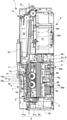
[도4]도1의A-A선 단면도로서 대기 상태에 있어서의 장치 본체의 내부 구조를 표시한 도이다.
[도5]실시 형태에 관한 제1지폐 수납부 전면의 상방으로부터 본 사시도이다.
[도6]도1의A-A선 단면도로서 제1 지페 수납부를 제거한 상태를 표시한 도이다.
[도7]도1의B-B선 단면도로서 대기 상태에 있어서의 장치본체의 내부구조를 표시한 도이다.
[도8]도1의 C-C선 단면도이다.
[도9]도1의D-D선 단면도이다.
[도10]도1의E-E선 단면도이다.
[도11]실시형태에 관한 지폐 처리 장치의 작용도이고, 스택 가이드 (stack guide) 를 후방으로 이동시키는 동작을 설명하는 도이다.
[도12]도1의A-A선 단면도로서 제1지폐를 급송하는 상태를 표시한 도이다.
[도13]도1의 B-B선 단면도로서 제1지폐를 급송하는 상태를 표시한 도이다.[Fig. 1] It is a perspective view of the banknote processing apparatus which concerns on embodiment of this invention.
[FIG. 2] It is a front view of the banknote processing apparatus shown in FIG.
[Fig. 3] Fig. 3 is a diagram schematically showing the internal structure of the apparatus main body according to the embodiment.
[Fig. 4] Fig. 4 is a cross-sectional view taken along line A-A in Fig. 1, showing the internal structure of the device main body in the standby state.
Fig. 5 is a perspective view seen from above of the front surface of the first banknote accommodating part according to the embodiment.
[Fig. 6] It is a cross-sectional view taken along line A-A of Fig. 1, showing a state in which the first paper money receiving part is removed.
[Fig.7] It is a cross-sectional view taken along line B-B in Fig. 1, showing the internal structure of the device body in the standby state.
[Fig. 8] It is a cross-sectional view taken along the line C-C in Fig. 1.
[Fig. 9] It is a cross-sectional view taken along the line D-D in Fig. 1.
[Fig. 10] It is a cross-sectional view along the line E-E of Fig. 1. [Fig.
[FIG. 11] It is an operation drawing of the banknote processing apparatus which concerns on embodiment, and is a figure explaining the operation|movement which moves a stack guide (stack guide) backward.
[Fig. 12] It is a sectional view along the line A-A of Fig. 1, showing the state in which the first banknote is delivered.
[Fig.13] It is a sectional view along the line B-B in Fig. 1, showing the state in which the first banknote is delivered.
이하, 첨부도면을 참조하여, 본 발명을 실시하기 위한 형태 (이하, 「실시형태」로 칭한다) 에 관해 상세히 설명한다. 이후의 설명에는, 앞선 지폐 처리 장치의 구성을 설명하고, 그 후, 지폐 처리 장치에 있어서의 제1지폐의 수납 동작 및 급송 동작에 대해서 설명한다. 또한, 실시형태의 설명의 전체를 통해 동일한 요소에는 동일한 번호를 부여하고 있다. 또한, 실시형태에 있어서는, 지폐를 삽입하는 지폐 삽입구가 배설되는 측을 정면으로 정의하고, 「전」、「후」는, 각각, 지폐 처리 장치를 정면으로부터 본 때의「앞쪽」、「안쪽」를 표시한다. 또한, 「좌」、「우」는, 각각, 지폐 처리 장치를 정면으로부터 본 때의「좌」,「우」를 표시한다.DETAILED DESCRIPTION OF THE PREFERRED EMBODIMENTS Hereinafter, modes for carrying out the present invention (hereinafter referred to as “embodiments”) will be described in detail with reference to the accompanying drawings. In the following description, the structure of the previous banknote processing apparatus is demonstrated, and the accommodation operation|movement and feeding operation|movement of the 1st banknote in a banknote processing apparatus are demonstrated after that. In addition, the same number is attached|subjected to the same element throughout description of embodiment. Further, in the embodiment, the side where the banknote insertion port for inserting the banknote is disposed is defined as the front side, and "front" and "rear" are respectively "front" and "inside" when the banknote processing apparatus is viewed from the front. to display In addition, "left" and "right" respectively indicate "left" and "right" when the banknote processing apparatus is viewed from the front.
(지폐 처리 장치의 전체 구성)(Overall configuration of bill processing equipment)
우선, 지폐 처리 장치의 전체 구성을 도1 및 도2에 기초하여 설명한다.First, the whole structure of a banknote processing apparatus is demonstrated based on FIG.1 and FIG.2.
도1은 지폐 처리 장치의 사시도, 도2는 도1에 표시된 지폐 처리 장치의 정면도이다.1 is a perspective view of the banknote processing apparatus, FIG. 2 is a front view of the banknote processing apparatus shown in FIG.
도1 및 도2에서 보이는 바와 같이, 지폐 처리 장치 1 은, 장치 본체1a 와, 장치 본체1a의 정면에 설치되어 있는 지폐 삽입구 21 과, 지폐 삽입구 21 의 상방 근방에 배치되고, 장치 본체 1a 의 정면에 설치되어 있는 지폐 지불구 22 를 구비하고, 거스름돈 지폐로서 사용 가능하고 또한 장치 본체 1a 의 내부를 순환 가능한 제1지폐 M1및 거스름돈 지폐로서 사용되지 않는 지폐인 장치 본체1a 의 내부를 순환하지 않는 제 2 지폐 M 2 를 지폐 삽입구 21 로부터 받는 기능을 갖는 것과 함께, 제 1 지폐 M1 을 지폐 지불구 22 로부터 지불하는 기능을 갖는다. 또한, 이하의 설명에는, 제1지폐 M1및 제2지폐 M 2 를 총칭하는 경우, 단순히 지폐로 기재하는 경우가 있다.1 and 2 , the
(지폐 처리 장치의 각부의 구성) (configuration of each part of the banknote processing apparatus)
다음으로, 지폐 처리 장치의 각부의 구성을 도 3및 도 4 ~ 도 10에 기초하여 설명한다. 또한, 도 3은, 장치 본체의 내부 구조의 주요 구성요소의 배치를 알기 쉽게 설명하기 위해, 장치 본체 및 그의 내부 구조를 모식적으로 표시하고 있다.Next, the structure of each part of a banknote processing apparatus is demonstrated based on FIG. 3 and FIGS. 4-10. Fig. 3 schematically shows the device body and its internal structure in order to clearly explain the arrangement of the main components of the device body's internal structure.
(지폐 반송 통로의 구성)(Configuration of banknote conveyance passage)
도 3 에서 보이는 바와 같이, 지폐 처리 장치1에는, 지폐가 반송되는 지폐 반송 통로 2 가 설치된다. 이 지폐 반송 통로 2 는, 장치 본체 1a 의 내부에 설치되는 통로로서, 지폐 삽입구 21 을 상류끝으로 하고, 지폐 지불구 22의 상부를 하류끝으로 하는 단일의 경로로 구성된다. 즉, 지폐 반송통로2는, 지폐 삽입구 21로부터 받아들여진 제1지폐M1을, 장치본체 1a 의 내부를 순환시켜 지폐 지불구 22에 반송가능하고, 지폐 삽입구 21로부터 받아들여진 제1지페 M1을 하방으로 반송하는 제1반송통로2a와, 하방으로 반송된 제1의 지폐 M1을 상방으로 반송하는 제2 반송통로 2b와, 상방으로 반송된 제1지폐 M1 을 지폐 지불구 22를 향해 하방으로 반송하는 제3반송통로 2c 를 갖는다.As shown in FIG. 3 , the
지폐 반송 통로 2 에 있어서는, 상류로부터 순서대로, 지폐 식별부 3, 제1지폐 수납부 6, 지폐 급송기구 8 및 제2지폐 수납부 9 가 설치되어 있다. 지폐 식별부 3은, 제 1반송통로 2a 에 설치되어, 지폐 삽입구 21로부터 받아들여진 지폐의 종류 (지폐의 진위 및 금전 종류) 를 식별한다. 제1지폐 수납부 6은, 제2반송통로2b 상에 지폐 삽입구 21 및 지폐 식별부 3 에 대향하도록 탈착 가능하게 설치되고, 제1지폐 M1을 수직자세로 재적 수납한다. 지폐 급송기구 8 은, 제1지폐 수납부 6 안의 제1지폐 M1 을 한장씩 급송하여 하류에 반송하는 기능을 갖는다. 제2지폐 수납부 9는, 제1지폐 수납부 6 의 하류측에 설치되어, 지폐 반송로 2 를 순환하지 않는 제2지폐 M2 를 수직자세로 재적 수납한다.In the
지폐 반송로 2의 각 부분에는, 지폐를 하류에 반송하는 지폐 반송 수단이 설치되어 있고, 이 지폐 반송 수단은, 반송 모터에 의해 구동하고, 구동 풀리와 수개의 종동 풀리와의 사이에 현가된 반송 벨트와, 이 반송 벨트에 압접하는 복수의 종동 롤러에 의해 지폐 반송 통로 2 안을 통과하는 지폐를 협지 (挾持) 하여 지폐 반송 통로 2 안을 반송시키는 것이 일반적이다.Each part of the
또한, 제1지폐 수납부 6 의 상류측에 배치된 제1지폐 반송 수단 4, 및 제1지폐 수납부 6 안의 상류측에 배치된 제2 지폐 반송 수단 5의 각각의 구성에 관해서는, 제1지폐 수납부 6 의 구성과 함께 후술하지만, 그 이외의 부위의 지폐 반송 수단에 대해서는, 종래 기술이 적용가능하고, 상세한 설명은 생략하는 것으로 한다.In addition, regarding the respective configurations of the first
지폐 반송 통로 2 의 상류끝에 있어서의 지폐 삽입구 21의 근방에, 지폐 삽입구 21로부터 삽입된 지폐를 검지하는 입구 센서가 배설되어 있다. 지폐 처리 장치 1에는, 이 입구 센서의 검출 출력에 기초하여, 지폐 삽입구 21에 삽입된 지폐를 지폐 반송 통로 2 의 하류에 반송하는 지폐 반송 수단이 구동되는 것으로 한다.In the vicinity of the
한편, 지폐 반송 통로 2 의 하류끝에는 출금 센서 (도시 생략) 가 배설되어 있다. 지폐 처리 장치 1에는, 출금 센서에 의해, 지폐 지불구 22 로 배출하는 지폐의 매수를 카운트한다. 게다가, 지폐 지불구 22의 지폐 처리 장치 1 의 정면측에는, 지폐 지불구 22 를 개폐하는 셔터 23이 설치되어 있다. 지폐 지불구 22 는, 셔터 23이 열리는 때에, 복수의 제1지폐 M1을 일괄하여 꺼내는 것 (지불) 이 가능하도록 상하방으로 크게 개구가능하다. 셔터23 은, 지폐 지불구 22 안에 반환한다. 또는, 지불하는 지폐의 매수가 전부 갖추어지기까지는, 지폐 지불구 22를 폐쇄하고, 이에 의해, 지불의 도중에 이용자가 거스름돈 지폐를 회수해버리거나, 남은 거스름돈 지폐를 가져가는 것을 잊어버리는 것 등이 방지된다.On the other hand, at the downstream end of the
(지폐 식별부의 구성) (Configuration of banknote identification unit)
도 4에서 보이는 바와 같이, 지폐 식별부 3 에 있어서는, 자기 센서 및 광 센서로 이루어지는 복수의 식별 센서를 제 1반송 통로 2a 의 주위에 배치하고, 각 식별센서가 제1 반송 통로 2a 안을 통과하는 지폐의 소정의 위치를 탐지하는 것에 의해 지폐의 물리적 특징을 검출한다. 지폐 처리 장치 1 에는, 이 검출 출력에 기초하여 지폐의 진위 및 금전의 종류가 종합 판정된다.As shown in Fig. 4, in the
또한, 입구 센서, 출금 센서, 셔터 23, 자기 센서 및 광 센서의 구성에 대해서는 종래 기술이 적용가능하고, 상세한 설명은 생략한다.In addition, the prior art is applicable to the configuration of the entrance sensor, the withdrawal sensor, the
(제1 지폐 수납부의 구성)(Configuration of the first banknote compartment)
도4 ~ 도6 에서 보이는 바와 같이, 제1지폐 수납부 6 은, 유닛으로서 일체화되어, 장치 본체 1a 에 대해서 후방으로부터 수평 방향으로 빼내는 것이 가능하게 장착되고, 지폐 식별부 3 보다도 하류에 위치한다. 보다 구체적으로는, 제1지폐 수납부 6 은, 수직방향으로 연장해 있는 제2 반송통로 2b 상에 배설된다.4 to 6 , the first
제1지폐 수납부6의 본체의 양측면에는, 단면 볼록형상 및 수평으로 형성한 가이드 리브 61 (도5에 있어서 도시를 생략한 좌방의 측면에도 좌우대칭으로 설치되어 있는 것으로 한다) 를 형성하고 있고, 가이드 리브 61 가, 제1지폐 수납부 6의 측벽과 계합하는 장치 본체 1a 의 내측벽 11 에 형성한 단면 오목 형상의 가이드 홈 12 (도 6 에 있어서 도시를 생략한 우방의 내측벽에도 좌우 대칭으로 설치되어 있는 것으로 한다) 에 맞물리도록, 제1지폐 수납부 6를 장치 본체 1a 로부터 수평으로 슬라이딩 시키는 것에 의해 장착한다.On both sides of the main body of the first
장착한 제1지폐 수납부 6 의 장치 본체 1a 에의 고정은, 제1 지폐 수납부 6 후단에 배설한 래치 (latch) 기구 62 에 의해 행한다 (도 5 에 있어서 도시를 생략한 좌방의 측면에도 좌우 대칭으로 설치되어 있는 것으로 한다)The attached first
상기 래치 (latch) 기구 62 는, 래치 (latch) 기구 62 를 좌우로부터 내측으로 향하여 누르기 위한 조작부 63 와, 래치 기구(latch) 62 를 좌우 외측으로 향하여 상시 힘을 가할 수 있는 부세 수단 (압축 스프링) (도시 생략) 과, 조작부 63와 연동하도록 좌우 외측으로 향하여 볼록 설치된 돌출부 64a, 64b 를 구비하고, 제1 지폐 수납부 6 가 장치 본체 1a 에 장착되어 있는 상태에 있어서는, 돌출부64a, 64b 가, 장치 본체1a 의 내측벽 11 에 형성한 래치 계지부13a, 13b 에 계합하도록 하는 것에 의해, 제1 지폐 수납부 6 를 장치 본체 1a 에 고정한다.The
또한, 조작부 63 은, 작업자가 한손으로 파지하고 또한 좌우로부터 누를 수 있도록 설치되고, 조작부 63 를 좌우로부터 중심 방향으로 누르고, 돌출부 64a, 64b 를 래치 계지부 13a, 13b 로부터 해제하여, 장치 본체 1a 와의 계합을 해제함과 함께, 조작부 63 을 파지한 채 후방으로 꺼내는 것에 의해, 지폐 처리 장치 1 을 기기 (도시 생략) 에 배설한 상태로 제1 지폐 수납부 6 를 제거하는 것이 가능한 구성으로도 좋다.In addition, the
그리고, 제1 지폐 수납부 6 의 본체의 상방은, 수납된 제1지폐 M1의 회수 및 거스름돈 지폐용 제1 지폐 M1 의 보충이 가능하도록 개방되어 있다.And the upper part of the main body of the 1st
제1 지폐 수납부 6 의 내부는, 크게 나누면, 제2반송 통로 2b 보다도 후방위치에 배치된 제1 지폐 수납고 67 과, 제2 반송 통로 2b 보다도 전방위치에 배치된 제1지폐 수납 기구 7 로 이루어 진다. 제 1 지폐 수납부 6에는, 제 2 반송통로 2b 상인 제 1 지폐 수납고 67 에 대향하는 위치에 있는 제 1 지폐 M1 을, 제1지폐 수납 기구 7 에 의해, 한장씩 제 1지폐 수납고 67 안에 수납한다.The interior of the first
제1지폐 수납고 67은, 제2 반송 통로 2b 를 통과하는 제1지폐 M1 에 대하여 평행하게 배치된 약 직사각형의 판상이고 전면에 제1 지폐 M1 을 정렬 적재하는 스택 플레이트 68과, 제1지폐 수납부 6 의 본체와 스택 플레이트 68를 연결하여 스택 플레이트 68 을 전방으로 상시 힘을 가하는 부세수단 (압축 스프링) 69a, 69b 를 구비한다.The
제1지폐 수납 기구 7은, 제1지폐 M1의 긴 방향 측 가장 자리를 가이드하는 한 쌍의 오목부 (슬릿) 72 를 각각 갖는 한 쌍의 스택 가이드 71 과, 제1지폐 M1의 좌우 중심부의 전방으로의 이동을 규제하는 유지판 74과, 스택 가이드 71 과 제1지폐 수납부6의 본체와 연결하여 스택 가이드71을 전후 이동시키는 한쌍의 왕복수단과, 제1지폐 수납부 6 내의 상류측에 있어서 지폐 반송 통로2를 통과하는 지폐의 전면에 당접하여 지폐를 상방으로 보내는 제2지폐 반송 수단 5를 구비한다.The first
또한, 한 쌍의 왕복 수단 및 한 쌍의 스택 가이드 71 는, 각각 좌우 대칭으로 설치되어 있는 것으로 하고, 이하, 일방의 구성에 대하여 설명하는 것으로 한다.In addition, a pair of reciprocating means and a pair of
도 7에서 보이는 바와 같이, 왕복 수단은, 상하에 병설한 두개의 리프트 캠 75a, 75b와, 이들 리프트 캠75a, 75b 의 사이에 개재하는 제1연결 기어 77로 이루어지고, 장치 본체 1a 에 배설한 수납 동작 구동 수단에 의해 구동되는 것이다.As shown in Fig. 7, the reciprocating means consists of two
리프트 캠 75a,75b는、제 1 지폐 수납부 6 의 본체에 회전자재로 베어링되어 있고, 좌우 수평 방향으로 회전축을 갖아 상호간에 동일한 방향으로 회전하도록 설계되어 있다. 그리고, 이들 리트프 캠75a,75b 의 외측면의 회전 중심으로부터 떨어진 위치에는, 외측방에 향하여 볼록하게 설계된 원주 형상의 돌기76a,76b 를 형성하고 있다.The lift cams 7.5a and 7.5b are rotatably bearing in the body of the first
제1연결 기어 77는, 제1지폐 수납부 6의 본체에 회전자재로 베어링되어 있고, 또한 리프트 캠75a,75b 와 맞물리도록 배설되어 있고, 수납 동작 구동 수단에 의해 회전 작동되어, 그 회전력을 리프트 캠75a,75b 에 전달하는 것이다.The
또한, 수납 동작 구동 수단은, 장치 본체 1a 에 배설된 제1전달 기어 14 (도 6 참조) 와, 모터 (도시 생략) 와, 이 모터의 회전력을 제1전달 기어 14 에 전달하는 기어열 (도시 생략) 로 이루어지는 것이고, 제1전달 기어 14는, 제1 지폐 수납부 6가 장치 본체 1a 에 장착되는 때에, 제 1 연결 기어 77 와 맞물리도록 배설되어 있다.Further, the housing operation driving means includes a first transmission gear 14 (see Fig. 6) disposed on the apparatus
스택 가이드 71 는, 그 자세를 유지한체 제1지폐 수납부 6의 본체에 대하여 전후방향으로 슬라이딩 하게끔 베어링 되어 있다.The
또한, 스택 가이드 71 에는, 좌우 방향으로 관통하고 또한, 돌기 76a 의 상사점과 돌기 76b 의 하사점과의 사이와 약 동일한 높이의 긴 구멍 73 을 형성하고, 긴 구멍 73 내측으로부터 리프트 캠 75a, 75b 의 돌기 76a, 76b 를 감삽하여, 리프트 캠75a, 75b 와 스택 가이드 71 이 캠 구조를 형성함에 따라, 리프트 캠75a, 75b 의 회전 운동에 수반하여 스택 가이드 71 이 전후방으로 왕복 직선 이동하도록 하고 있다.Further, in the
스택 가이드 71의 오목부 72 는, 제 2 반송 통로 2b 의 도중 부분 (제2반송 통로 2b 의 양측부의 전후면 및 양측 가장자리) 을 형성가능하다. 그리고, 입금된 지폐의 반송 위치와 수납을 마친 제1지폐와는, 스택 가이드 71에 의해 일정한 틈을 갖고, 제1지폐 M1이 지폐의 반송의 방해가 안되도록 구성된다.The
즉, 스택 가이드 71 은, 제1지폐 수납고 67에 수납한 제1지폐M1이 지폐 반송통로 2 측으로 돌아가는 것을 저지하는 기능과, 지폐 반송통로 2에 있는 지폐를 제1지폐 수납고 67로의 투입을 저지하는 기능과, 지폐 반송통로 2에 있어서 지폐의 긴방향측 가장자리의 통로폭을 규제하는 벽으로서의 기능을 갖을 수 있도록 구성되어 있다. 그리고, 스택 가이드 71은, 장치 본체 1a 에 대해서 좌우 방향 및 상하 방향으로의 이동이 규제되어, 반송 방향에 대해 수직 방향만 가동하도록 구성되어 있는 것으로 한다.That is, the
또한, 상기 각 기능을 갖는 것이라면, 스택 가이드 71의 형상은 임의이고, 예를 들어, 지폐 반송통로2와 제1지폐 수납고 67를 사이에 두는 벽과 지폐의 긴방향측 가장자리의 통로폭을 규제하는 벽을 일체적으로 설치하는 것도, 별도로, 설치하는 것도 가능하다.In addition, as long as it has each of the above functions, the shape of the
유지판 74 (도5참조) 는, 대기 상태에 있어서 오목부 72 의 앞측벽과 약 동일 평면상에 후벽을 갖고, 좌우 스택 가이드 71 사이에 개재하도록 제1지폐 수납부 6 의 본체에 고정되어 있는 것이다. 이 유지판 74 는, 지페 수납 동작시에 있어서 스택 가이드 71가 전방으로 이동하는 때에, 스택 가이드 71 안의 제1지폐 M1의 전면에 당접하여 제1지폐M1의 전방으로의 이동을 규제한다. 그리고, 제1지폐 M1의 양측 가장자리가 오목부 72로부터 떨어져, 제1지폐 M1이 스택 가이드 71보다 후방에 침투하고, 제1지폐 M1이 제1지폐 수납고67안의 스택 플레이트 68상에 수납되도록 하고 있다.The holding plate 74 (refer to Fig. 5) has a rear wall approximately flush with the front side wall of the
(제2지폐 반송 수단의 구성)(Configuration of means for returning the second bill)
도7~도9에 보이는 바와 같이, 제2지폐 반송수단 5는, 오목부 72보다 전방인 스택 가이드 71의 소정의 위치에 좌우 방향으로 회전축을 갖도록 축지지된 구동 샤프트 51과, 구동 샤프트 51을 회전축으로서 좌우 대칭으로 또한, 오목부 72의 전면측으로부터 지폐 반송 통로 2 안에 약간 돌출하도록 설치된 한쌍의 반송 롤러 52와, 구동 샤프트 51을 회전축으로서 그 우단에 설치된 제2연결 기어 53 (도10참조) 과, 오목부 72보다 후방인 스택 가이드 71의 소정의 위치에 좌우 대칭으로 배설된 한쌍의 압축 롤러 암 54 (도10 참조) 과, 각 반송 롤러 52 와 대향하도록 각 압축 롤러 암 54 에 회전자재로 베어링된 한쌍의 압축 롤러 56 를 갖는다.7 to 9 , the second
압축 롤러 암 54 은, 오목부 72와 약 평행한 판상으로, 탄성을 갖고, 또한 하단을 고정 설치하고, 상부가 전후로 약간 요동할 수 있도록 설치되어 있다. 압축 롤러 암 54의 상단에는 외측에 돌설된 압축부 55 를 형성하고, 상하 중앙부의 반송 롤러 52와 대향하는 위치에는 압축 롤러 56 를 축지지 하고 있고, 압축부 55 를 전방으로 압축하면 압축 롤러 56 가 반송 롤러 52에 당접하고, 압축하지 않으면 반송 롤러 52와 압축 롤러 56 가 약간 이간을 하도록 하고 있다.The
그리고, 제1지폐 수납부 6 의 본체에는, 추가로, 일방의 단부가 제1지폐 수납부 6 의 본체에 고정되고, 타방의 단부가 자유단으로서, 우측방에서 볼 때 (도10참조) 에 있어서, 반시계 방향으로 힘을 갖는 부세수단 (토션 스프링) 65 를 설치하고 있다. 이 부세수단 65 의 자유단은, 대기 상태에 있어서는, 압축부 55 를 전방으로 힘을 가하고 있다. 한편, 지폐 수납 동작시에 있어서 스택 가이드 71 가 전방으로 이동한 때에는, 제1지폐 수납부 6의 본체에 형성한 스프링 계지부 66 에 의해 부세수단 65 의 자유단의 전방으로의 이동이 규제되고, 압축부 55 와 부세수단 65 과의 계합이 해제된다.And, in the body of the first
제2지폐 반송 수단 5은, 전용 구동원을 가지지 않고, 제1지폐 수납부6의 상류측의 장치본체 1a 에 배치된 제1지폐 반송수단 4 의 구동력이, 제2연결 기어 53를 개재하여 전달되는 것에 의해, 구동 샤프트 51가 회전한다.The second
(제1지폐 반송 수단의 구성)(Configuration of the first banknote conveying means)
도10에서 보이는 바와 같이, 제1지폐 반송 수단 4는, 모터 (도시 생략) 및 이 모터의 회전력을 풀리 41b 및 제2전달 기어43에 전달하는 기어열 (도시 생략) 로 이루어지는 반송 동작 구동 수단과, 풀리 41a, 41b 및 부호를 부여하지 않은 수개의 풀리와, 이들 풀리간에 현가된 반송벨트와, 반송벨트에 압접하는 롤러 42 및 부호를 부여하지 않은 수개의 롤러를 구비한다.As shown in Fig. 10, the first
제2전달 기어43은, 대기 상태에 있어서, 제2연결 기어53의 수직 하방에 배치되어, 또한 제2연결 기어 53과 맞물리도록 배설되고, 제1지폐 반송 수단 4 의 구동력을 제2연결 기어 53을 개재하여 제2지폐 반송수단 5에 전달한다. 한편, 지폐 수납동작시에는, 스택 가이드 71이 전방으로 이동하는 것에 의해 제2기어53과 제2전달 기어43과의 계합이 해제된다.In the standby state, the
또한, 제2전달 기어43과 제2연결 기어 53과는 수직 방향으로 접하고 있고, 그리고, 장치 본체 1a 에 제1지폐 수납부6을 탈착하는 때에는 제1지폐 수납부 6을 수평방향으로 슬라이딩 시키기 때문에, 탈착시에 제2전달기어43이 제2연결 기어 53을 저해하는 일은 없다.In addition, since the
(지폐 급송 기구의 구성) (Composition of banknote feeding mechanism)
도7에 보이는 바와 같이, 제1지폐 수납부 6의 하류측으로부터 제2지폐 수납고 91에 이르기까지의 사이에는 지폐 급송 기구 8이 설치되어 있고, 제1지폐 수납고 67안에 수납된 제1지폐 M1 중, 최후에 수납된 (가장 전방에 위치한다) 제1지폐 M1 만을 급송하고, 그 한장을 분리시켜 제2반송 통로 2b 의 하류에 반송하는 것에 의해, 제1지폐M1을 반환 가능하도록 하고 있다.As shown in Fig. 7, a
지폐 급송 기구 8은, 제2반송 통로 2b상에 설치되어, 제1지폐 수납부 6에 수납된 제1지폐 M1을 급송하는 기능을 갖는다. 지폐 급송 기구 8은, 급송 롤러 (픽업 롤러) 81과, 송출 롤러 (피드 롤러) 82와, 저지 롤러 (게이트 롤러) 83으로 구성되고, 각각 장치 본체 1a 에 대해서 축 지지 되어 있다.The
급송 롤러 81은, 제2반송 통로 2b 를 사이에 두고 제1지폐 수납고67과 대향하는 제1지폐 수납부6의 하류부에 설치되어 있고, 스택 플레이트 68에 정렬 적재된 제1지폐 M1중, 가장 전방에 위치하는 제1지폐 M1 을 급송하여 제2 반송 통로 2b 의 하류에 반송하는 기능과, 제2지폐 M2 를 제2반송 통로 2b의 하류에 반송하는 기능과, 제1지폐 M1을 제1지폐 수납고 67안에 수납하는 때에, 유지판 74와 함께 제1지폐 수납고 67안에 수납되어 있는 제1지폐 M1을 누르는 기능을 갖는다.The feeding
송출 롤러 82 및 저지 롤러 83은, 급송 롤러 81의 하류에 있어서, 포개진 형태로 맞물리도록 대향 배치되어, 급송 롤러 81에 의해 제1지폐M1 이 급송되는 때에는, 저지 롤러 83의 회전을 정지시켜, 송출 롤러 82만의 회전력으로 제1지폐 M1을 하류에 반송시키는 것에 의해, 제1지폐M1을 한장씩 분리하도록 하고 있다. 또한, 제1지폐 M2 의 입금시는, 송출 롤러 82 및 저지 롤러 83을 함께 반송 방향으로 회전시켜 제2지폐 M2가 원할하게 반송되도록 되어 있다.The dispensing
또는, 송출 롤러 82 및 저지 롤러 83과 제2지폐 수납부 9와의 사이에는, 급송 센서를 배설하여, 송출 롤러 82 및 저지 롤러 83에 있어서, 급송된 제1지폐 M1이, 바르게 한장씩 분리되었는지 아닌지를 확인하도록 하고 있다.Alternatively, a feeding sensor is provided between the dispensing
(제2 지폐 수납부의 구성) (Configuration of the second banknote accommodating part)
도7에서 보이는 바와 같이, 제2지폐 수납부 9는, 지폐 급송 기구 8 보다 하류로 제1지폐 수납부 6 의 상방에 배설된다. 제2지폐 수납부 9는, 크게 나누면, 제2반송통로 2b 의 후방에 배치된 제2지폐 수납고 91과, 전방에 배치된 제2지폐 지폐 수납 기구 (도시 생략) 로 이루어지고, 제2반송 통로2b에 있어서 제2의 지폐 수납고 91에 대향하는 위치에 있는 제2지페 M2를, 제2지폐 수납 기구에 의해, 한장씩 제2지폐 수납고 91안에 수납하도록 구성된다.As shown in Fig. 7 , the second
또한, 제2지폐 수납고 91 및 제2지폐 수납 기구의 구성에 대해서는, 상세한 설명은 생략하지만, 예를 들어, 특허4728538 호 공보에 기재된 링크 기구로 이루어지는 리프트 테이블 등의 기술을 적용하는 것이 가능하다.In addition, although detailed description is omitted about the structure of the
(지폐 처리 장치의 동작) (Operation of banknote processing device)
이상과 같이 구성된 지폐 처리 장치 1에 있어서, 제1지폐 M1의 수납시 및 급송시의 일련의 동작을 도 11~ 도 13에 기초하여 설명한다.In the
(제1지폐의 수납) (Storage of the first banknote)
도 11 에서 보이는 바와 같이, 지폐 삽입구 21부터 제 1지폐 M1이 삽입되면, 상류부의 지폐 반송 수단이 구동하고, 제1의 지폐 M1이 제1반송 통로2a의 하류에 반송된다. 그리고, 제1지폐 반송 수단 4 를 개재하여 구동이 전달되는 제 2 지폐 반송 수단 5 가 작동한다.As shown in FIG. 11, when the 1st banknote M1 is inserted from the
이때, 스택 가이드 71가 전후 방향에 있어서 제2반송 통로 2b와 일치하는 위치까지 후방으로 이동하여, 제1지폐 M1이 제2반송 통로 2b 상을 반송한다.At this time, the
제1지폐 M1 은, 제1지폐 수납부 6에 도달하면, 반송 롤러 52와 압축 롤러 56 에 의해 협지된 스택 가이드 71의 오목부 72를 따라 하류로 반송된다. 제1지폐 M1 이 제1지폐 수납고 67에 대향하는 위치에 달하면, 제1지폐 반송 수단 4의 구동이 정지하고, 제1지폐 M1을 그 장소에 정지시켜 수납 동작으로 이동하고, 수납 동작 구동 수단이 구동한다.When the first banknote M1 reaches the first
제1전달 기어 14가 왼쪽 (도6에 있어서 제1전달 기어14의 반시계 방향) 으로 회전하면, 왕복수단의 제1연결 기어77을 개재하여 리프트 캠 75a, 75b 가 작동하고, 왼쪽으로 회전한다. 리프트 캠75a, 75b 의 돌기 76a, 76b 가 스택 가이드 71의 긴 구멍 73 안을 이동하는 것에 의해, 스택 가이드 71가 전방으로 이동을 개시한다.When the
그러면, 스택 가이드 71 과 함께 제2지폐 반송 수단 5 이 전방으로 이동하기 때문에, 제2전달 기어43과 제2연결 기어53 과의 맞물림이 해제됨게 함께, 부세수단 65에 의해 압축 롤러 암 54의 압축부55로의 압축이 해제되어, 제1지폐 M1의 협지가 해제된다.Then, since the second
추가로 리프트 캠 75a, 75b 가 왼쪽으로 회전하면, 스택 가이드 71이 제2반송 통로 2b 보다도 전방으로 이동하는 것에 의해, 스택 가이드 71에 의해 제1지폐 M1 로의 압축이 해제되어, 대신 제1지폐 M1으로부터의 압축을 급송 롤러 81 및 유지판 74이 받는다.Additionally, when the
이에 따라, 제1지폐 M1은, 좌우방향으로의 엇갈림이 방지된 상태로 급송 롤러 81 및 유지판 74 로 협지된 상태가 되고, 스택 가이드 71이 보다 전방으로 이동하면, 제1지폐 M1의 긴 방향측 가장자리가 스택 가이드 71의 오목부 72로부터 상대적으로 꺼내지게 되고, 스택 가이드 71의 최대 이동위치에 이르기까지 오목부 72로부터 빠져나간다.Accordingly, the first banknote M1 is in a state sandwiched by the feeding
또한, 리프트 캠 75a, 75b 가 왼쪽으로 회전하면, 스택 가이드 71이 후방으로 복귀함과 함께, 제1지폐 M1이 제1지폐 수납고 67내에 수납되어, 대기상태로 돌아간다.Further, when the
(제1지폐의 급송)(Rapid delivery of the first bill)
도 12 및 도13에 보이는 바와 같이, 제1지폐 수납고 67안에 수납되어 있는 제 1지폐 M1을 반환하는 때에는, 스택 가이드 71을 전방으로 이동시켜, 가장 전방에 위치하는 제 1지폐M1을 급송 롤러 81측으로 압축한 상태로, 급송 롤러 81 을 회전시켜 급송한다. 그리고 급송한 제1지폐 M1을, 송출 롤러 82 및 저지 롤러 83 에 있어서, 한장씩 분리하여, 제2반송 통로 2b 의 하류로 반송한다.12 and 13, when returning the first banknote M1 stored in the
이 때, 제1지폐M1을 한장씩 분리 불가하고, 두장씩 겹쳐진 상태로 하류에 반송되어, 상술한 도시하지 않은 급송 센서에 의해 제1지폐 M1의 두장 겹쳐짐을 검출한 경우에는, 제1지폐 M1을 제2지폐 수납고 91에 수납하고, 다시, 반환 동작을 행하고, 제1지폐 수납고 67로부터 제1지폐 M1을 급송하는 것에 의해, 계산 착오를 방지할 수 있다.At this time, the first banknote M1 cannot be separated one by one, and is conveyed downstream in a state of overlapping two by one. Calculation error can be prevented by storing in the
(실시형태의 효과)(Effect of embodiment)
이하, 설명한 실시형태의 효과에 대해서 서술한다.Hereinafter, the effect of embodiment demonstrated is demonstrated.
본 실시형태에 의하면, 장치 본체 1a 의 정면에 있어서 지폐 삽입구 21 의 근방에 지폐 지불구 22 를 배치함과 함께 지폐 지불구 22에 셔터 23을 설치한 구성으로 하고, 지폐 삽입구 21과 지폐 지불구 22 를 연결하는 단일 경로의 지폐 반송통로 2 를 장치 본체 1a 의 내부에 설치하고, 이 지폐 반송통로 2 상에, 지폐 식별부 3, 제1지폐 수납부 6, 제2 지폐 수납부 9 및 지폐 급송 기구 8 을 컴팩트하게 배치하기 때문에, 지폐 처리 장치 1의 소형화 및 경량화를 도모하는 것이 가능하다. 따라서, 예를 들어, 종래, 거스름돈 지폐를 일괄하여 꺼내는 것이 가능한 지폐 처리 장치는, 그 질량이 15kg 이상의 대형이었지만, 본 실시형태에서는, 질량을 약 5kg정도로 억제하고, 게다가 거스름돈 지폐를 일괄하여 꺼내는 것이 가능한 소형 지폐 처리 장치 1 을 제공하는 것이 가능하다.According to this embodiment, in the front of the apparatus
또한, 지폐 지불구 22 를 지폐 삽입구 21의 상방 근방에 배치하기 때문에, 지폐 지불구 22에 있어서 제1 지폐 M1을 일괄하여 꺼내는 것이 가능함께 함께, 지폐를 삽입하거나 받는 이용자의 손의 이동을 최소한으로 억제하는 것이 가능하기 때문에, 제1지폐M1을 받는 것이 쉽고, 빠른 사용성을 얻을 수 있다.In addition, since the
그리고, 단일 경로의 지폐 반송 통로 2 에 의해, 반송 벨트나 풀리 등의 부품의 배치가 용이하고, 또한, 부품수를 억제함이 가능함과 함께, 지폐 반송경로가 짧아지기 때문에, 지폐의 막힘을 방지 가능하고, 지폐를 원할히 반송하는 것이 가능하다. 또한, 지폐 반송 경로 2 를 개방하는 구성이 용이하게 실현가능하기 때문에, 가령 지폐 막힘이 발생해도, 지폐 막힘의 해소가 용이하다.And, by the single-path
게다가, 저액 지폐를 수용하는 제1지폐 수납부6의 하류에, 고액 지폐를 수납하는 제2지폐 수납부 9를 설치하는 것에 의해, 제1지폐 수납부 6 으로부터 제1지폐M1 (예를 들어, 천엔) 을 급송하는 때에 제1지폐 M1가 2장 이상 겹쳐져 송출되는 것을 검출한 경우에는, 제2지폐 수납부 9에 그 제1지폐 M1을 수납하는 것이 가능하게 된다. 이 때문에, 2장으로 겹쳐진 제1지폐 M1 을 퇴피시키는 지폐 수납고를 별도로 설치할 필요가 없다. 따라서, 지폐 처리 장치 1 의 소형화를 유지한 체로 장치 본체 1a의 내부에 있어서 제1 지폐 M1을 과잉으로 지불하는 경우도 방지하는 추가 효과도 얻을 수 있다.Furthermore, by providing the second
이상, 실시형태를 이용하여 본 발명을 설명했지만, 본 발명의 기술적 범위는 상기 실시형태에 기재의 범위에 한정되지 않음은 당연하다. 상기 실시형태에, 다양한 변경 또는 개량을 가할 수 있음은 당업자에게 분명하다. 또한 그러한 변경 또는 개량을 더한 형태도 본 발명의 기술범위에 포함되는 것이 가능하지만, 특허청구범위의 기재로부터 명확한 것이다.As mentioned above, although this invention was demonstrated using embodiment, it is natural that the technical scope of this invention is not limited to the range described in the said embodiment. It is clear to those skilled in the art that various changes or improvements can be added to the above embodiment. Moreover, although it is possible to include the form which added such a change or improvement to the technical scope of this invention, it is clear from description of a claim.
1 지폐 처리 장치
1a 장치 본체
2 지폐 반송통로
2a 제 1 반송통로
2b 제 2 반송통로
2c 제 3 반송통로
21 지폐삽입구
22 지폐지불구
23 셔터
3 지폐 식별부
6 제1지폐 수납부
8 지폐 급송 기구
9 제2지폐 수납부
M1 제1지폐
M2 제2지폐1 banknote handling device
1a Device body
2 Banknote return passage
2a 1st conveyance passage
2b 2nd conveying passage
2c 3rd conveyance passage
21 banknote slot
22 banknote payment area
23 shutter
3 Banknote identification section
6 1st banknote compartment
8 Banknote feeder
9 2nd bill compartment
M1 1st banknote
M2 2nd banknote
Claims (7)
장치 본체와,
상기 장치 본체의 정면에 설치되어 있는 지폐 삽입구와,
상기 지폐 삽입구의 근방에 배치되어, 상기 장치본체의 정면에 설치되어 있는 지폐 지불구와,
상기 지폐 지불구에 설치되어, 상기 지폐 지불구를 개폐하는 셔터와,
상기 장치본체의 내부에 설치된, 상류끝인 상기 지폐 삽입구와 하류끝인 상기 지폐 지불구를 연결하는 단일 경로의 지폐 반송 통로로, 상기 지폐 삽입구로부터 받아들여져, 거스름돈 지폐로서 사용가능한 제1 지폐를, 상기 장치본체의 내부를 상기 상류끝으로부터 상기 하류끝까지 일 방향으로 순환시켜 상기 지폐 지불구에 반송 가능한 지폐 반송 통로를 구비하고,
상기 지폐 지불구는, 상기 셔터가 열리게 됨에 따라, 복수의 상기 제1 지폐를 일괄하여 꺼내는 것이 가능하게 구성된 것을 특징으로 하는 지폐 처리 장치.In the banknote processing apparatus,
the device body;
a bill insertion port installed on the front of the device body;
a bill payment port disposed in the vicinity of the bill insertion port and installed on the front of the device body;
a shutter installed in the bill payment port to open and close the bill payment port;
A single-path banknote conveying passage connecting the banknote insertion port, which is the upstream end, and the banknote payment port, which is the downstream end, installed inside the device body, the first banknote received from the banknote insertion port and usable as change banknotes, and a banknote conveying passage capable of being conveyed to the banknote payment port by circulating the inside of the device body in one direction from the upstream end to the downstream end;
The banknote payment port is configured to be capable of taking out a plurality of the first banknotes at once as the shutter is opened.
상기 지폐 반송 통로가, 상기 지폐 삽입구로부터 받아들여진 상기 제1지폐를 하방으로 반송하는 제1 반송 통로와, 하방으로 반송된 상기 제 1 의 지폐를 상방으로 반송하는 제 2 반송 통로와, 상방으로 반송된 상기 제 1 지폐를 상기 지폐 지불구를 향하여 하방으로 반송하는 제 3 반송 통로를 갖는 것을 특징으로 하는 지폐 처리 장치.According to claim 1,
The banknote conveying passage includes a first conveying passage for conveying the first banknote received from the banknote insertion port downward, a second conveying passage for conveying the first banknote conveyed downward upward, and upward conveying It has a 3rd conveyance passage which conveys the said 1st banknote which was used downward toward the said banknote payment port, The banknote processing apparatus characterized by the above-mentioned.
상기 제 1 의 반송 통로에 설치되어, 상기 지폐 삽입구로부터 받아들여진 지폐의 종류를 식별하는 지폐 식별부를 추가로 구비하는 것을 특징으로 하는 지폐 처리 장치.3. The method of claim 2,
The banknote processing apparatus which is provided in the said 1st conveyance passage, and is further provided with the banknote identification part which identifies the kind of banknote received from the said banknote insertion port.
상기 제 2 반송 통로상에 상기 지폐 삽입구 및 상기 지폐 식별부에 대향하도록 탈착 가능하게 설치되어, 상기 제 1 지폐를 수납하는 제1 지폐 수납부와,
상기 제1 지폐 수납부의 하류측에 설치되어, 거스름돈 지폐로서 사용되지 않는 제2 지폐를 수납하는 제2 지폐 수납부를 추가로 구비하는 것을 특징으로 하는 지폐 처리 장치.4. The method of claim 3,
a first banknote accommodating part which is detachably installed so as to face the banknote insertion port and the banknote identification part on the second conveyance passage, and accommodates the first banknote;
The banknote processing apparatus which is provided on the downstream side of the said 1st banknote accommodating part, and is further provided with the 2nd banknote accommodating part which accommodates the 2nd banknote which is not used as a change banknote.
상기 제2 반송 통로상에 설치되어, 상기 제1 지폐 수납부에 수납된 상기 제1지폐를 급송하는 지폐 급송 기구를 추가로 구비하는 것을 특징으로 하는 지폐 처리 장치.5. The method of claim 4,
and a banknote feeding mechanism provided on the second conveying passage and feeding the first banknote accommodated in the first banknote accommodating portion.
장치 본체와,
상기 장치 본체의 정면에 설치되어 있는 지폐 삽입구와,
상기 지폐 삽입구의 근방에 배치되어, 상기 장치본체의 정면에 설치되어 있는 지폐 지불구와,
상기 장치본체의 내부에 설치된, 상류끝인 상기 지폐 삽입구와 하류끝인 상기 지폐 지불구를 연결하는 단일 경로의 지폐 반송 통로로, 상기 지폐 삽입구로부터 받아들여져, 거스름돈 지폐로서 사용가능한 제1 지폐를, 상기 장치본체의 내부를 상기 상류끝으로부터 상기 하류끝까지 일 방향으로 순환시켜 상기 지폐 지불구에 반송 가능한 지폐 반송 통로를 구비하고,
상기 지폐 반송 통로상에 탈착 가능하게 설치되어, 상기 제1 지폐를 수납하는 제1 지폐 수납부와,
상기 제1 지폐 수납부의 하류측에 설치되어, 거스름돈 지폐로서 사용되지 않는 제2 지폐를 수납하는 제2 지폐 수납부를 구비하는 것을 특징으로 하는 지폐 처리 장치. In the banknote processing apparatus,
the device body;
a bill insertion port installed on the front of the device body;
a bill payment port disposed in the vicinity of the bill insertion port and installed on the front of the device body;
A single-path banknote conveying passage connecting the banknote insertion port, which is the upstream end, and the banknote payment port, which is the downstream end, installed inside the device body, the first banknote received from the banknote insertion port and usable as change banknotes, and a banknote conveying passage capable of being conveyed to the banknote payment port by circulating the inside of the device body in one direction from the upstream end to the downstream end;
A first banknote accommodating part which is detachably installed on the banknote conveying passage and accommodates the first banknote;
and a second banknote accommodating part which is provided on the downstream side of the said 1st banknote accommodating part and accommodates the 2nd banknote which is not used as a change banknote, The banknote processing apparatus characterized by the above-mentioned.
상기 제1 지폐의 두장 겹쳐짐을 검출한 경우에, 두장 겹쳐짐의 상기 제1 지폐를 상기 제2 지폐 수납부에 수납하는 것을 특징으로 하는 지폐 처리 장치.
7. The method of claim 6,
The banknote processing apparatus characterized by storing the said 1st banknote of the overlapping of two sheets in the said 2nd banknote accommodating part, when the overlap of two sheets of the said 1st banknote is detected.
Applications Claiming Priority (3)
| Application Number | Priority Date | Filing Date | Title |
|---|---|---|---|
| JPJP-P-2015-093822 | 2015-05-01 | ||
| JP2015093822A JP6535921B2 (en) | 2015-05-01 | 2015-05-01 | Banknote processing device |
| PCT/JP2015/085375 WO2016178295A1 (en) | 2015-05-01 | 2015-12-17 | Banknote processing device |
Publications (2)
| Publication Number | Publication Date |
|---|---|
| KR20180002601A KR20180002601A (en) | 2018-01-08 |
| KR102377915B1 true KR102377915B1 (en) | 2022-03-23 |
Family
ID=57217585
Family Applications (1)
| Application Number | Title | Priority Date | Filing Date |
|---|---|---|---|
| KR1020177026493A KR102377915B1 (en) | 2015-05-01 | 2015-12-17 | banknote handling device |
Country Status (5)
| Country | Link |
|---|---|
| JP (1) | JP6535921B2 (en) |
| KR (1) | KR102377915B1 (en) |
| CN (1) | CN107430796B (en) |
| HK (1) | HK1247427A1 (en) |
| WO (1) | WO2016178295A1 (en) |
Citations (3)
| Publication number | Priority date | Publication date | Assignee | Title |
|---|---|---|---|---|
| JP2000057404A (en) * | 1998-08-03 | 2000-02-25 | Mamiya Op Co Ltd | Paper money storing device |
| JP3980291B2 (en) | 2001-03-30 | 2007-09-26 | 芝浦メカトロニクス株式会社 | Paper sheet transport device |
| JP2008176747A (en) * | 2007-01-22 | 2008-07-31 | Toyo Networks & System Integration Co Ltd | Circulating bank note processing apparatus |
Family Cites Families (12)
| Publication number | Priority date | Publication date | Assignee | Title |
|---|---|---|---|---|
| JPS62290671A (en) | 1986-06-10 | 1987-12-17 | Fuji Electric Co Ltd | Stacking/storing mechanism for paper sheets |
| JPS6391794A (en) * | 1986-10-07 | 1988-04-22 | Hitachi Electronics Eng Co Ltd | Note counting processing system |
| JP2932338B2 (en) * | 1993-11-05 | 1999-08-09 | 株式会社日本コンラックス | Banknote handling equipment |
| KR100308610B1 (en) * | 1997-10-06 | 2001-12-12 | 가나이 쓰토무 | The bills treatment apparatus |
| JPH11339098A (en) * | 1998-05-22 | 1999-12-10 | Nippon Conlux Co Ltd | Paper money processor |
| JP3931527B2 (en) * | 2000-03-29 | 2007-06-20 | 富士電機リテイルシステムズ株式会社 | Banknote storage device |
| JP5759289B2 (en) * | 2011-06-30 | 2015-08-05 | グローリー株式会社 | Banknote processing apparatus and banknote management method |
| JP5786694B2 (en) * | 2011-12-05 | 2015-09-30 | 沖電気工業株式会社 | Banknote handling equipment |
| JP5821585B2 (en) * | 2011-12-05 | 2015-11-24 | 沖電気工業株式会社 | Banknote handling equipment |
| JP5821588B2 (en) * | 2011-12-06 | 2015-11-24 | 沖電気工業株式会社 | Banknote handling equipment |
| CN202548955U (en) * | 2012-04-16 | 2012-11-21 | 深圳市怡化电脑有限公司 | Depositing and withdrawing all-in-one machine |
| JP6227397B2 (en) * | 2013-12-20 | 2017-11-08 | 株式会社日本コンラックス | Banknote handling equipment |
-
2015
- 2015-05-01 JP JP2015093822A patent/JP6535921B2/en active Active
- 2015-12-17 KR KR1020177026493A patent/KR102377915B1/en active IP Right Grant
- 2015-12-17 WO PCT/JP2015/085375 patent/WO2016178295A1/en active Application Filing
- 2015-12-17 CN CN201580078703.9A patent/CN107430796B/en active Active
-
2018
- 2018-05-23 HK HK18106660.6A patent/HK1247427A1/en unknown
Patent Citations (3)
| Publication number | Priority date | Publication date | Assignee | Title |
|---|---|---|---|---|
| JP2000057404A (en) * | 1998-08-03 | 2000-02-25 | Mamiya Op Co Ltd | Paper money storing device |
| JP3980291B2 (en) | 2001-03-30 | 2007-09-26 | 芝浦メカトロニクス株式会社 | Paper sheet transport device |
| JP2008176747A (en) * | 2007-01-22 | 2008-07-31 | Toyo Networks & System Integration Co Ltd | Circulating bank note processing apparatus |
Also Published As
| Publication number | Publication date |
|---|---|
| CN107430796A (en) | 2017-12-01 |
| KR20180002601A (en) | 2018-01-08 |
| JP2016212540A (en) | 2016-12-15 |
| CN107430796B (en) | 2020-06-16 |
| WO2016178295A1 (en) | 2016-11-10 |
| JP6535921B2 (en) | 2019-07-03 |
| HK1247427A1 (en) | 2018-09-21 |
Similar Documents
| Publication | Publication Date | Title |
|---|---|---|
| JP4655777B2 (en) | Banknote deposit and withdrawal machine | |
| KR20140009487A (en) | Bill storage box and bill handling device | |
| KR20060132509A (en) | Bill handling device | |
| KR20060132480A (en) | Bill processor | |
| JP6547344B2 (en) | Medium storage and medium handling device | |
| KR102377915B1 (en) | banknote handling device | |
| JP5005022B2 (en) | Banknote handling equipment | |
| WO2016103927A1 (en) | Paper currency processing device | |
| WO2013172084A1 (en) | Paper-slip handling device and automated transaction device | |
| WO2009093716A1 (en) | Device for processing paper sheets or the like | |
| KR101865141B1 (en) | Paper currency processing device | |
| KR102312025B1 (en) | Paper currency processing device | |
| KR20060042403A (en) | Apparatus for paper money | |
| WO2016140141A1 (en) | Banknote storage cassette, banknote handling system, and banknote handling method | |
| JP2013003973A (en) | Paper money processor | |
| JP2017090986A (en) | Paper sheet storing cassette, and paper sheet processing device | |
| KR102002948B1 (en) | Media transfer module and financial device thereof | |
| JP2005004375A (en) | Bank bill discriminating device | |
| JPH08161580A (en) | Paper money storage device | |
| JP5051923B2 (en) | Banknote handling equipment | |
| JP2019066962A (en) | Medium storage and automatic transaction device | |
| JP6832178B2 (en) | Paper leaf processing equipment | |
| JP2010280493A (en) | Paper sheet processing device | |
| KR101764508B1 (en) | Medium storage box and financial device | |
| JP2010211278A (en) | Paper sheet processing apparatus |
Legal Events
| Date | Code | Title | Description |
|---|---|---|---|
| A201 | Request for examination | ||
| E902 | Notification of reason for refusal | ||
| E701 | Decision to grant or registration of patent right |