KR102304574B1 - Chemical mechanical planarization pad conditioner with elongated cutting edges - Google Patents
Chemical mechanical planarization pad conditioner with elongated cutting edges Download PDFInfo
- Publication number
- KR102304574B1 KR102304574B1 KR1020167029446A KR20167029446A KR102304574B1 KR 102304574 B1 KR102304574 B1 KR 102304574B1 KR 1020167029446 A KR1020167029446 A KR 1020167029446A KR 20167029446 A KR20167029446 A KR 20167029446A KR 102304574 B1 KR102304574 B1 KR 102304574B1
- Authority
- KR
- South Korea
- Prior art keywords
- delete delete
- elongate
- protrusions
- cmp
- conditioning
- Prior art date
Links
Images


Classifications
-
- H—ELECTRICITY
- H01—ELECTRIC ELEMENTS
- H01L—SEMICONDUCTOR DEVICES NOT COVERED BY CLASS H10
- H01L21/00—Processes or apparatus adapted for the manufacture or treatment of semiconductor or solid state devices or of parts thereof
- H01L21/02—Manufacture or treatment of semiconductor devices or of parts thereof
- H01L21/04—Manufacture or treatment of semiconductor devices or of parts thereof the devices having at least one potential-jump barrier or surface barrier, e.g. PN junction, depletion layer or carrier concentration layer
- H01L21/18—Manufacture or treatment of semiconductor devices or of parts thereof the devices having at least one potential-jump barrier or surface barrier, e.g. PN junction, depletion layer or carrier concentration layer the devices having semiconductor bodies comprising elements of Group IV of the Periodic System or AIIIBV compounds with or without impurities, e.g. doping materials
- H01L21/30—Treatment of semiconductor bodies using processes or apparatus not provided for in groups H01L21/20 - H01L21/26
- H01L21/302—Treatment of semiconductor bodies using processes or apparatus not provided for in groups H01L21/20 - H01L21/26 to change their surface-physical characteristics or shape, e.g. etching, polishing, cutting
- H01L21/304—Mechanical treatment, e.g. grinding, polishing, cutting
-
- B—PERFORMING OPERATIONS; TRANSPORTING
- B24—GRINDING; POLISHING
- B24B—MACHINES, DEVICES, OR PROCESSES FOR GRINDING OR POLISHING; DRESSING OR CONDITIONING OF ABRADING SURFACES; FEEDING OF GRINDING, POLISHING, OR LAPPING AGENTS
- B24B53/00—Devices or means for dressing or conditioning abrasive surfaces
- B24B53/017—Devices or means for dressing, cleaning or otherwise conditioning lapping tools
-
- B—PERFORMING OPERATIONS; TRANSPORTING
- B24—GRINDING; POLISHING
- B24B—MACHINES, DEVICES, OR PROCESSES FOR GRINDING OR POLISHING; DRESSING OR CONDITIONING OF ABRADING SURFACES; FEEDING OF GRINDING, POLISHING, OR LAPPING AGENTS
- B24B37/00—Lapping machines or devices; Accessories
- B24B37/11—Lapping tools
- B24B37/20—Lapping pads for working plane surfaces
-
- B—PERFORMING OPERATIONS; TRANSPORTING
- B24—GRINDING; POLISHING
- B24D—TOOLS FOR GRINDING, BUFFING OR SHARPENING
- B24D5/00—Bonded abrasive wheels, or wheels with inserted abrasive blocks, designed for acting only by their periphery; Bushings or mountings therefor
- B24D5/06—Bonded abrasive wheels, or wheels with inserted abrasive blocks, designed for acting only by their periphery; Bushings or mountings therefor with inserted abrasive blocks, e.g. segmental
-
- H—ELECTRICITY
- H01—ELECTRIC ELEMENTS
- H01L—SEMICONDUCTOR DEVICES NOT COVERED BY CLASS H10
- H01L21/00—Processes or apparatus adapted for the manufacture or treatment of semiconductor or solid state devices or of parts thereof
- H01L21/02—Manufacture or treatment of semiconductor devices or of parts thereof
- H01L21/04—Manufacture or treatment of semiconductor devices or of parts thereof the devices having at least one potential-jump barrier or surface barrier, e.g. PN junction, depletion layer or carrier concentration layer
- H01L21/18—Manufacture or treatment of semiconductor devices or of parts thereof the devices having at least one potential-jump barrier or surface barrier, e.g. PN junction, depletion layer or carrier concentration layer the devices having semiconductor bodies comprising elements of Group IV of the Periodic System or AIIIBV compounds with or without impurities, e.g. doping materials
- H01L21/30—Treatment of semiconductor bodies using processes or apparatus not provided for in groups H01L21/20 - H01L21/26
- H01L21/302—Treatment of semiconductor bodies using processes or apparatus not provided for in groups H01L21/20 - H01L21/26 to change their surface-physical characteristics or shape, e.g. etching, polishing, cutting
- H01L21/306—Chemical or electrical treatment, e.g. electrolytic etching
- H01L21/30625—With simultaneous mechanical treatment, e.g. mechanico-chemical polishing
-
- B—PERFORMING OPERATIONS; TRANSPORTING
- B24—GRINDING; POLISHING
- B24B—MACHINES, DEVICES, OR PROCESSES FOR GRINDING OR POLISHING; DRESSING OR CONDITIONING OF ABRADING SURFACES; FEEDING OF GRINDING, POLISHING, OR LAPPING AGENTS
- B24B53/00—Devices or means for dressing or conditioning abrasive surfaces
- B24B53/12—Dressing tools; Holders therefor
-
- B—PERFORMING OPERATIONS; TRANSPORTING
- B24—GRINDING; POLISHING
- B24D—TOOLS FOR GRINDING, BUFFING OR SHARPENING
- B24D2203/00—Tool surfaces formed with a pattern
Abstract
연마 패드를 컨디셔닝하기 위한 CMP 패드 컨디셔너. 본 개시내용의 다양한 실시예는 CMP 패드 컨디셔너가 연마 패드와 결합할 때 다양한 접촉각으로 연마 패드의 피컨디셔닝 표면을 가공하는 복수의 세장형 돌출부를 포함한다. 돌출부의 세장형 형상에 기인하여, 다양한 접촉각은 다면적인 방식으로 연마 패드의 피컨디셔닝 면을 굴곡시키는 경향을 갖는다. 피컨디셔닝 면의 이런 다면적 조작은 컨디셔너 조립체의 절삭율 및 CMP 프로세스로부터 잔류되는 연마 패드의 공극 내의 이물의 제거를 향상시켜 연마 패드의 공극을 더 양호하게 개방시키고 CMP 프로세스에서의 제거율을 더 양호하게 유지시킨다는 것을 발견하였다. CMP pad conditioner for conditioning polishing pads. Various embodiments of the present disclosure include a plurality of elongate protrusions that work the conditioned surface of the polishing pad at various contact angles when the CMP pad conditioner engages the polishing pad. Due to the elongate shape of the protrusion, various contact angles tend to bend the conditioned face of the polishing pad in a multifaceted manner. This multi-faceted manipulation of the conditioned face improves the removal rate of the conditioner assembly and the removal of foreign matter in the voids of the polishing pad remaining from the CMP process to better open the voids of the polishing pad and maintain a better removal rate in the CMP process. found that it does.
Description
관련 출원Related applications
본 출원은 2014년 3월 21일자로 출원된 미국 가출원 제61/968,846호에 대한 혜택을 주장하며, 그 내용은 본 명세서에 그 전문이 참조로 통합되어 있다.This application claims the benefit of US Provisional Application No. 61/968,846, filed March 21, 2014, the contents of which are incorporated herein by reference in their entirety.
발명의 분야field of invention
본 개시내용은 일반적으로 반도체 제조 장비에 관한 것이다. 더 구체적으로, 본 개시내용은 반도체의 제조시 사용되는 연마 패드의 세정을 위한 컨디셔닝 장치에 관한 것이다. The present disclosure relates generally to semiconductor manufacturing equipment. More specifically, the present disclosure relates to a conditioning apparatus for cleaning a polishing pad used in the manufacture of semiconductors.
화학 기계 연마(CMP)는 반도체 제조에 방대하게 사용된다. CMP 프로세스 동안, 연마 패드, 연마 슬러리 및 선택적으로, 화학 시약의 작용에 의해 웨이퍼 기재로부터 물질이 제거된다. 시간 경과에 따라, 연마 패드는 헝클어지고 CMP 프로세스로부터의 이물이 채워지게 된다. 주기적으로, 연마 패드는 패드 컨디셔너를 사용하여 다시 컨디셔닝되며, 패드 컨디셔너는 연마 패드 표면을 마모시켜 공극을 열고 연마 패드의 표면 상에 조면부를 생성한다. 패드 컨디셔너의 기능은 CMP 프로세스에서의 제거율을 유지하는 것이다. Chemical mechanical polishing (CMP) is extensively used in semiconductor manufacturing. During the CMP process, material is removed from the wafer substrate by the action of a polishing pad, polishing slurry, and, optionally, chemical reagents. Over time, the polishing pad becomes matted and becomes filled with debris from the CMP process. Periodically, the polishing pad is reconditioned using a pad conditioner, which abrades the surface of the polishing pad to open pores and create a roughness on the surface of the polishing pad. The function of the pad conditioner is to maintain the removal rate in the CMP process.
CMP는 반도체 및 메모리 장치의 제조시 주요한 생산 비용을 나타내게 된다. 이들 CMP 비용은 연마 패드, 연마 슬러리, 패드 컨디셔닝 디스크 및 평탄화 및 연마 작업 동안 마모되는 다양한 CMP 부품과 연계된 비용을 포함한다. CMP 프로세스를 위한 추가적 비용은 연마 패드의 교체를 위한 공구 가동중단시간 및 CMP 연마 패드를 재조정하기 위한 테스트 웨이퍼의 비용을 포함한다. CMP represents a major production cost in the manufacture of semiconductors and memory devices. These CMP costs include the costs associated with polishing pads, polishing slurries, pad conditioning disks, and various CMP components that are worn during planarization and polishing operations. Additional costs for the CMP process include tool downtime for the replacement of the polishing pad and the cost of the test wafer to recondition the CMP polishing pad.
통상적 연마 패드는 폐쇄-셀 우레탄 발포체를 포함한다. 패드 컨디셔닝 동안, 패드는 패드 표면의 셀구조 층을 통한 물리적 절삭을 위해 기계적 마모를 받게 된다. 연마 패드의 노출 표면은 개방 셀을 포함하며, 이는 CMP 프로세스 동안 웨이퍼로부터 제거된 물질 및 소진된 연마 슬러리 같은 이물을 포획하게 된다. 각각의 후속 패드 컨디셔닝 단계에서, 패드 컨디셔너는 매립된 물질을 포함하는 셀의 외부 층을 제거하고 외부 층 아래의 층의 제거를 최소화한다. 연마 패드의 초과-텍스쳐형성은 수명 단축을 초래하고, 부족-텍스쳐형성은 CMP 단계 동안 불충분한 재료 제거율 및 웨이퍼 균일성의 결여를 초래하게 된다. A typical polishing pad comprises a closed-cell urethane foam. During pad conditioning, the pad is subjected to mechanical wear for physical cutting through the cellular layer of the pad surface. The exposed surface of the polishing pad contains open cells, which trap contaminants such as spent polishing slurry and material removed from the wafer during the CMP process. In each subsequent pad conditioning step, the pad conditioner removes the outer layer of the cell containing the buried material and minimizes the removal of the layer below the outer layer. Over-texturing of the polishing pad results in shortened lifetime, and under-texturing results in insufficient material removal rate and lack of wafer uniformity during the CMP step.
연마 패드로부터의 과도한 재료 제거 없이 더 양호하게 제어된 패드 절삭율을 위해 이물의 제거를 향상시키는 개선된 CMP 패드 텍스쳐형성 기능을 갖는 CMP 패드 컨디셔너에 대한 지속적 수요가 존재한다. There is a continuing need for CMP pad conditioners with improved CMP pad texturing capabilities that enhance the removal of debris for better controlled pad cut rates without excessive material removal from the polishing pad.
본 개시내용의 다양한 실시예는 CMP 패드 컨디셔너가 연마 패드와 결합할 때 다양한 스윕각으로 연마 패드의 피컨디셔닝 표면을 가공하기 위한 적어도 하나의 융기부 라인을 형성하는 복수의 세장형 돌출부를 포함한다. 돌출부의 세장형 형상에 기인하여, 다양한 스윕각이 제공되며, 이는 다면적인 방식으로 연마 패드의 피컨디셔닝 면을 굴곡시키는 경향을 갖는다. 피컨디셔닝 면의 이런 다면적 조작은 컨디셔너 조립체의 절삭율 및 CMP 프로세스로부터 잔류되는 연마 패드의 공극 내의 이물의 제거를 향상시켜 연마 패드의 공극을 더 양호하게 개방시키고 CMP 프로세스에서의 제거율을 더 양호하게 유지시킨다는 것을 발견하였다. 배열 및 설명된 세장형 돌출부는 통상적 피라미드 돌출부에 비해 25%만큼 CMP 패드 컨디셔너의 절삭율(예를 들어, μm/hr)을 향상시키는 것으로 관찰되었다.Various embodiments of the present disclosure include a plurality of elongate protrusions that form at least one ridge line for processing a conditioned surface of a polishing pad at various sweep angles when the CMP pad conditioner engages the polishing pad. Due to the elongated shape of the protrusion, various sweep angles are provided, which tend to bend the conditioned face of the polishing pad in a multifaceted manner. This multi-faceted manipulation of the conditioned face improves the removal rate of the conditioner assembly and the removal of foreign matter in the voids of the polishing pad remaining from the CMP process to better open the voids of the polishing pad and maintain a better removal rate in the CMP process. found that it does. The arrayed and described elongate protrusions were observed to improve the cut rate (eg, μm/hr) of CMP pad conditioners by 25% compared to conventional pyramidal protrusions.
세장형 돌출부에 수반되는 세장형 에지 형상은 첨단부형(예를 들어, "피라미드") 돌출부보다 더 강한 돌출부의 추가적인 이득을 제공할 수 있다. 즉, 세장형 에지를 가로질러 작용함으로써, 작업 응력은 첨단부형 구성보다 더 큰 전단 영역에 걸쳐 전달되고, 그에 의해, 강도를 개선시키며, 더 소수의 파손을 유발하며, 이러한 파손은 CMP 패드 컨디셔너로부터의 비의도적 이물로 연마 패드를 더럽힐 수 있다.The elongated edge shape accompanying the elongated protrusion may provide the additional benefit of a stronger protrusion than a pointed (eg, “pyramid”) protrusion. That is, by acting across the elongated edge, the working stress is transferred over a larger shear area than the tip configuration, thereby improving strength and causing fewer breaks, which breakage away from the CMP pad conditioner. The polishing pad may be soiled with unintentional foreign matter.
일부 실시예에서, 세장형 돌출부는 다공성 기재로부터 형성된다. 다공도는 성형 프로세스에서 공극이 노출되기 때문에 고유한 조면도를 제공한다. 결과적인 조면도는 CMP 컨디셔닝 패드의 절삭율을 추가로 향상시킨다. 일부 실시예에서, 결과적 조면도는 초연마 그릿 입자의 구현을 증강시키며, 초연마 그릿 입자는 구현 조면화된 표면 상에 그릿을 더 양호하게 포획하는 것에 의해 세장형 돌출부에 결합될 수 있다.In some embodiments, the elongate protrusions are formed from a porous substrate. Porosity provides a unique roughness because the voids are exposed in the forming process. The resulting roughness further improves the cut rate of the CMP conditioning pad. In some embodiments, the resulting roughness enhances the implementation of the superabrasive grit particles, which can be bonded to the elongate protrusions by better trapping grit on the implemented roughened surface.
일부 실시예에서, 조면화된 세장형 돌출부는 세장형 돌출부의 높이 분포에 고유한 변동을 추가로 제공한다. 높이의 변동은 연마 패드의 피컨디셔닝 표면의 가공을 추가로 개선시킬 수 있으며, 그 이유는, 서로 다른 높이가 컨디셔닝 동안 연마 패드의 피컨디셔닝 표면의 다양한 정도의 변위를 유발하기 때문이다. 일부 실시예에서, 돌출부 높이의 변동은 상이한 사전결정된 높이로 의도적으로 목표설정된다. 즉, 기재는 둘 이상의 서로 다른 평균 높이를 갖도록 형성된다. In some embodiments, the roughened elongate protrusion further provides an inherent variation in the height distribution of the elongate protrusion. Variation in height can further improve processing of the conditioned surface of the polishing pad, since different heights cause varying degrees of displacement of the conditioned surface of the polishing pad during conditioning. In some embodiments, variations in protrusion height are intentionally targeted to different predetermined heights. That is, the substrate is formed to have two or more different average heights.
일부 실시예는 세장형 돌출부 및/또는 기재 위에 경질의 내구성있는 코팅을 구현하며, 이는 일반적으로 컨디셔닝 패드의 내구성을 향상시킨다.Some embodiments implement a hard, durable coating over the elongate protrusions and/or substrate, which generally improves the durability of the conditioning pad.
일부 종래의 CMP 패드 컨디셔너는 컨디셔너의 가공면 상의 연마제 그릿, 예컨대, 다이아몬드 입자를 사용하는 것에 의해 조면화된 표면을 제공한다. 그릿은 통상적으로 에폭시 또는 금속 매트릭스 물질 내에 고착된다. 다른 CMP 패드 컨디셔너는 Smith 등의 국제 특허 출원 공보 제WO 2012/122186호에 개시된 것 같은 CMP 패드 컨디셔너의 면에 수직으로 돌출하는 조면화된 돌출부를 구현한다. 또 다른 CMP 패드 컨디셔너는 Doering 등의 국제 특허 출원 공보 제WO 2013/166516에 개시된 것 같은 초연마 그릿 및 조면화된 돌출부의 조합을 사용한다. 이들 종래의 CMP 패드 컨디셔너는 또한 통상적으로 그릿 및/또는 돌출부 위에 코팅, 예로서, CVD 다이아몬드 코팅을 사용한다. Some conventional CMP pad conditioners provide a roughened surface by using abrasive grits, such as diamond particles, on the machined surface of the conditioner. The grit is typically fixed in an epoxy or metal matrix material. Other CMP pad conditioners implement roughened protrusions that protrude perpendicular to the face of the CMP pad conditioner as disclosed in International Patent Application Publication No. WO 2012/122186 to Smith et al. Another CMP pad conditioner uses a combination of superabrasive grit and roughened protrusions as disclosed in International Patent Application Publication No. WO 2013/166516 to Doering et al. These conventional CMP pad conditioners also typically use a coating over the grit and/or protrusion, eg, a CVD diamond coating.
복수의 세장형 돌출부를 그와 일체로(즉, 단일체) 구비하는 전방 표면을 포함하는 기재를 갖는 화학 기계 연마 패드 컨디셔너에 의해 개선된 CMP 패드 절삭율이 달성될 수 있다. 복수의 세장형 돌출부는 전방 표면에 수직인 전방 방향으로 돌출하며, 복수의 세장형 돌출부 각각은 세장형 융기부 라인을 형성한다. 일 실시예에서, 복수의 세장형 돌출부는 정합 평면의 변동 이내에서 복수의 세장형 돌출부의 사전결정된 서브세트를 포함하고, 정합 평면은 전방 표면에 실질적으로 평행하며, 사전결정된 서브세트의 세장형 돌출부는 서로에 대해 고정되고 사전결정된 관계로 정합 평면 상에 위치된다. 다양한 실시예에서, 다결정 다이아몬드 코팅이 사전결정된 서브세트의 적어도 세장형 융기부 라인을 덮는다. 일부 실시예에서, 기재는 적어도 10 %의 다공도를 갖는다. Improved CMP pad ablation rates may be achieved by chemical mechanical polishing pad conditioners having a substrate comprising a front surface integrally (ie, monolithic) with a plurality of elongate protrusions. The plurality of elongate protrusions protrude in a forward direction perpendicular to the front surface, and each of the plurality of elongate protrusions defines a line of elongate ridges. In one embodiment, the plurality of elongate protrusions includes a predetermined subset of the plurality of elongate protrusions within a variation of the mating plane, the mating plane substantially parallel to the anterior surface, the predetermined subset of elongate protrusions are positioned on the mating plane in a fixed and predetermined relationship with respect to each other. In various embodiments, a polycrystalline diamond coating covers at least the line of elongate ridges of the predetermined subset. In some embodiments, the substrate has a porosity of at least 10%.
다양한 실시예에서, 초연마 그릿 입자의 분산체가 세장형 돌출부와 기재 상에 배치된다. 일부 실시예에서, 코팅은 기재, 세장형 돌출부 및 초연마 그릿 입자의 분산체를 덮는다. In various embodiments, a dispersion of superabrasive grit particles is disposed on the elongate protrusion and the substrate. In some embodiments, the coating covers the substrate, the elongate protrusions and the dispersion of superabrasive grit particles.
본 개시내용의 CMP 패드 컨디셔너의 다른 형태는 기재 바닥으로부터 연장하는 그와 일체인 복수의 세장형 돌출부를 구비하는 전방 표면을 갖는 기재를 포함하고, 복수의 세장형 돌출부는 컨디셔너의 전방 표면에 수직인 전방 방향으로 돌출하고, 복수의 세장형 돌출부는 반복적 간격 패턴으로 배열된다. 다양한 실시예에서, 세장형 돌출부는 기재 바닥 레벨로부터 측정된 평균 높이를 갖는다. 일부 실시예에서, 초연마 그릿 입자의 분산체가 복수의 세장형 돌출부를 포함하는 기재 상에 배치될 수 있고, 세장형 돌출부를 포함하는 기재와 초연마 그릿 입자의 분산체를 코팅이 덮는다. 다양한 실시예에서, 코팅은 CVD 다이아몬드 코팅이다.Another form of a CMP pad conditioner of the present disclosure includes a substrate having a front surface having a plurality of elongate projections integral therewith extending from a bottom of the substrate, the plurality of elongate projections being perpendicular to the front surface of the conditioner. Projecting in the forward direction, the plurality of elongate projections are arranged in a repeating spacing pattern. In various embodiments, the elongate protrusions have an average height measured from the substrate floor level. In some embodiments, a dispersion of superabrasive grit particles may be disposed on a substrate comprising a plurality of elongated protrusions, wherein the coating covers the substrate comprising the elongated protrusions and the dispersion of superabrasive grit particles. In various embodiments, the coating is a CVD diamond coating.
다른 실질적 세장형 돌출부는 오각 주상형 형상, 직사각 주상형 형상, 육각 주상형 형상 등을 포함할 수 있다. 일부 실시예에서, 주상형 형상은 세장형 원위 에지를 포함하고, 이 세장형 원위 에지는 베이스 또는 세그먼트의 표면으로부터 가장 멀리 있다. 이 세장형 원위 에지는 돌출부의 제1 측방향 단부로부터 돌출부의 제2 측방향 단부로 연장한다. 주상부는 추가적 세장형 에지, 예로서, 오각 주상부에 형성될 수 있는 것들을 포함할 수 있다. 둥근 주상부 단면의 경우에, 주상부의 두 단부 사이의 최고위 영역이 세장형 원위 에지로 고려된다.Other substantially elongate protrusions may include pentagonal columnar shapes, rectangular columnar shapes, hexagonal columnar shapes, and the like. In some embodiments, the columnar shape comprises an elongated distal edge, the elongated distal edge being furthest from the surface of the base or segment. This elongated distal edge extends from a first lateral end of the protrusion to a second lateral end of the protrusion. The columnar may include additional elongated edges, such as those that may be formed in the pentagonal columnar portion. In the case of a round columnar cross-section, the highest region between the two ends of the columnar is considered an elongate distal edge.
구조적으로, 본 개시내용의 다양한 실시예에 대하여, 화학 기계 연마(CMP) 컨디셔닝 세그먼트는 전방 표면 및 그와 단일체인 복수의 세장형 돌출부를 포함하는 기재를 포함하고, 복수의 세장형 돌출부는 전방 면과 실질적으로 평행한 장축(enlongate axis)을 형성하고, 복수의 세장형 돌출부 각각은 장축의 방향으로 연장하는 적어도 하나의 융기부 라인을 포함하고, 복수의 세장형 돌출부는 전방 표면에 수직인 전방 방향으로 돌출한다. 복수의 세장형 돌출부 각각의 장축은 기재의 스윕 방향에 관하여 적어도 두 개의 각도 중 하나를 형성한다. 선택적으로, 복수의 세장형 돌출부는 복수의 클러스터로 그룹화되고, 복수의 클러스터 각각은 사전결정된 패턴을 형성하는 복수의 세장형 돌출부 중 둘 이상을 포함한다. 다양한 실시예에서, 적어도 하나의 융기부 라인은 둥글다. 일부 실시예에 대하여, 복수의 클러스터 각각은 사전결정된 위치에 위치된다. 일 실시예에서, 복수의 클러스터 각각은 스타버스트(starburst) 패턴을 형성한다. 선택적으로, 복수의 클러스터는 줄지어 또는 매트릭스 배열로 배열된다.Structurally, for various embodiments of the present disclosure, a chemical mechanical polishing (CMP) conditioning segment includes a substrate comprising a front surface and a plurality of elongate protrusions monolithic therewith, the plurality of elongate protrusions being monolithic therewith. and defining an enlongate axis substantially parallel to, each of the plurality of elongate projections including at least one line of ridges extending in the direction of the long axis, the plurality of elongate projections having a forward direction perpendicular to the anterior surface protrude to A major axis of each of the plurality of elongate projections defines one of at least two angles with respect to the sweep direction of the substrate. Optionally, the plurality of elongate protrusions are grouped into a plurality of clusters, each of the plurality of clusters comprising two or more of the plurality of elongate protrusions forming a predetermined pattern. In various embodiments, the at least one ridge line is rounded. For some embodiments, each of the plurality of clusters is located at a predetermined location. In one embodiment, each of the plurality of clusters forms a starburst pattern. Optionally, the plurality of clusters are arranged in a row or matrix arrangement.
다양한 실시예에서, 복수의 세장형 돌출부 중 적어도 일부의 적어도 하나의 융기부 라인의 융기부 라인은 복수의 우세 융기부 라인을 형성하기 위한 우세 융기부 라인이다. 일부 실시예에서, 우세 융기부 라인의 사전결정된 제1 서브세트는 제1 정합 평면의 제1 변동 내에 있는 원위 말단부를 포함하고, 우세 융기부 라인의 사전결정된 제2 서브세트는 제2 정합 평면의 제2 변동 내에 있는 원위 말단부를 포함한다. 제1 정합 평면은 전방 방향으로 제2 정합 평면으로부터 오프셋된다. 다양한 실시예에서, 오프셋 거리는 제1 변동과 제2 변동 중 적어도 하나 미만이다. 일부 실시예에서, 복수의 세장형 돌출부 중 적어도 일부의 적어도 하나의 융기부 라인은 동일평면에 있는 두 개의 융기부 라인을 포함한다. 일부 실시예에서, 동일평면에 있는 두 개의 융기부 라인 사이에 세장형 메사(mesa)가 형성된다. 다양한 실시예의 기재는 경계값을 포함하여 10% 내지 70%의 범위의 다공도를 가질 수 있다. In various embodiments, the ridge line of at least one ridge line of at least some of the plurality of elongate projections is a predominant ridge line for forming the plurality of predominant ridge lines. In some embodiments, the first predetermined subset of the predominant ridge line comprises a distal distal end that is within a first variation of the first mating plane, and wherein the second predetermined subset of the predominant ridge line is of a second mating plane. and a distal end within the second variation. The first mating plane is offset from the second mating plane in the forward direction. In various embodiments, the offset distance is less than at least one of the first variation and the second variation. In some embodiments, at least one ridge line of at least some of the plurality of elongate projections includes two coplanar ridge lines. In some embodiments, an elongate mesa is formed between two lines of ridges that are coplanar. The substrates of various embodiments may have a porosity in the range of 10% to 70% inclusive of the boundary value.
본 개시내용의 다양한 실시예에서, 상술한 CMP 컨디셔닝 세그먼트를 제조하는 방법은 기재를 제공하는 단계와, 주상형 형상의 윤곽선에 따라 복수의 세장형 돌출부를 형성하는 단계를 포함한다. 일 실시예에서, 주상형 형상은 삼각 주상형 형상이다. 제공 단계에서 제공되는 기재는 실리콘 카바이드를 포함하고, 선택적으로, 제공 단계에서 제공되는 기재는 그라파이트를 포함하고, 이 방법은 기계가공 단계 이후 그라파이트를 실리콘 카바이드로 변환하는 단계를 더 포함한다. 다양한 실시예에서, 형성 단계는 와이어 전기 방전 기계가공, 마스크식 마삭 기계가공, 수류 제트 기계가공, 광 마삭 기계가공, 레이저 기계가공 및 통상적 밀링 중 하나를 포함한다.In various embodiments of the present disclosure, a method of manufacturing a CMP conditioning segment as described above includes providing a substrate and forming a plurality of elongate protrusions along the outline of a columnar shape. In one embodiment, the columnar shape is a triangular columnar shape. The substrate provided in the providing step comprises silicon carbide, and optionally, the substrate provided in the providing step comprises graphite, and the method further comprises converting the graphite to silicon carbide after the machining step. In various embodiments, the forming step comprises one of wire electrical discharge machining, masked abrasive machining, water jet machining, light abrasive machining, laser machining, and conventional milling.
도 1은 본 개시내용의 실시예의 컨디셔너를 갖는 웨이퍼 연마 기기의 사시도이다.
도 2는 본 개시내용의 실시예의 컨디셔닝 세그먼트를 갖는 패드 컨디셔너의 사시도이다.
도 3a는 도 2의 이면 판에 장착되는 컨디셔닝 세그먼트의 이미지이다.
도 3b는 도 3a의 이미지의 확대 부분 이미지이다.
도 3c는 도 3a 및 도 3b의 스타버스트 돌출부 클러스터의 평면도이다.
도 4a는 본 개시내용의 실시예의 대안적 스타버스트 돌출부 클러스터를 사용하는 컨디셔닝 세그먼트의 평면도이다.
도 4b는 도 4a의 스타버스트 돌출부 클러스터의 평면도이다.
도 5는 본 개시내용의 실시예의 컬럼형 돌출부 클러스터를 사용하는 컨디셔닝 세그먼트의 평면도이다.
도 6은 본 개시내용의 실시예의 선형 돌출부 클러스터를 사용하는 컨디셔닝 세그먼트의 평면도이다.
도 7은 본 개시내용의 실시예의 삼각 주상형 돌출부의 등각도이다.
도 7a 내지 도 7c는 도 7의 삼각 주상형 돌출부의 정사투영도이다.
도 8은 본 개시내용의 실시예의 오각 주상형 돌출부의 등각도이다.
도 8a 내지 도 8c는 도 8의 오각 주상형 돌출부의 정사투영도이다.
도 9는 본 개시내용의 실시예의 절두체 주상형 돌출부의 등각도이다.
도 9a 내지 도 9c는 도 9의 절두체 주상형 돌출부의 정사투영도이다.
도 10은 도 3a 및 도 3b의 스타버스트 클러스터의 레이저 공초점 현미경 이미지이다.
도 10a는 도 10의 세장형 돌출부의 가상 단면이다.
도 11은 본 개시내용의 일 실시예에서 산재된 상이한 높이의 결과적 세장형 돌출부의 확대 측단면도이다.
도 12a 내지 도 12c는 본 개시내용의 실시예에서 상이한 형상비를 가지면서 초연마 입자를 사용하는 세장형 돌출부의 단면도이다.1 is a perspective view of a wafer polishing apparatus having a conditioner of an embodiment of the present disclosure;
2 is a perspective view of a pad conditioner with conditioning segments of an embodiment of the present disclosure;
3A is an image of a conditioning segment mounted to the back plate of FIG. 2 ;
FIG. 3B is an enlarged partial image of the image of FIG. 3A .
3C is a plan view of the starburst protrusion cluster of FIGS. 3A and 3B ;
4A is a top view of a conditioning segment using an alternative starburst protrusion cluster of an embodiment of the present disclosure.
FIG. 4B is a top view of the starburst protrusion cluster of FIG. 4A ;
5 is a top view of a conditioning segment using a columnar protrusion cluster of an embodiment of the present disclosure;
6 is a top view of a conditioning segment using a linear protrusion cluster of an embodiment of the present disclosure;
7 is an isometric view of a triangular columnar protrusion of an embodiment of the present disclosure;
7A to 7C are orthographic views of the triangular columnar protrusion of FIG. 7 ;
8 is an isometric view of a pentagonal columnar protrusion of an embodiment of the present disclosure;
8A to 8C are orthographic views of the pentagonal columnar protrusion of FIG. 8 .
9 is an isometric view of a frustum columnar protrusion of an embodiment of the present disclosure;
9A to 9C are orthographic views of the frustum columnar protrusion of FIG. 9 .
FIG. 10 is a laser confocal microscopy image of the starburst cluster of FIGS. 3A and 3B .
FIG. 10A is a virtual cross-section of the elongate protrusion of FIG. 10 ;
11 is an enlarged side cross-sectional view of the resulting elongate protrusions of different heights interspersed in one embodiment of the present disclosure;
12A-12C are cross-sectional views of elongated protrusions using superabrasive particles with different aspect ratios in embodiments of the present disclosure;
도 1을 참조하면, 화학 기계 평탄화(CMP) 프로세스의 패드 컨디셔너 조립체(32)를 구비하는 웨이퍼 연마 기기(30)가 본 개시내용의 일 실시예에서 도시되어 있다. 도시된 웨이퍼 연마 기기(30)는 연마 패드(38)(예컨대, 중합체 패드)가 그 위에 장착되어 있는 상부 면(36)을 구비하는 회전 테이블(34)을 포함한다. 연마 패드(38)는 가공 또는 피컨디셔닝 면(40)을 포함한다. 웨이퍼 기재(44)가 그 위에 장착되어 있는 웨이퍼 헤드(42)는 웨이퍼 기재(44)가 연마 패드(38)의 가공 면(40)과 접촉하도록 배열되어 있다. 일 실시예에서, 슬러리 공급 장치(46)가 연마제 슬러리(48)를 연마 패드(38)에 제공한다.1 , a
동작시, 회전 테이블(34)이 회전되고, 그래서, 연마 패드(38)가 웨이퍼 헤드(42), 패드 컨디셔너 조립체(32) 및 슬러리 공급 장치(46) 아래에서 회전한다. 웨이퍼 헤드(42)는 하향력(F)으로 연마 패드(38)와 접촉한다. 웨이퍼 헤드(42)는 또한 그 위에 장착된 웨이퍼 기재(44)의 연마를 증대시키기 위해 선형 전후 작용으로 진동 및/또는 회전될 수 있다. 패드 컨디셔너 조립체(32)는 또한 연마 패드(38)와 접촉한다. 패드 컨디셔너 조립체(32)는 통상적으로 회전되며, 또한, 연마 패드(38)의 표면을 가로질러 전후로 병진될 수도 있다. In operation, the rotary table 34 is rotated so that the
기능적으로, 연마 패드(38)는 제어된 방식으로 웨이퍼 기재(44)로부터 물질을 제거하여 웨이퍼 기재(44)에 연마된 마감을 제공한다. 패드 컨디셔너 조립체(32)의 기능은 CMP 프로세스로부터의 이물이 채워진 연마 동작으로부터 이물을 제거하고, 연마 패드(38)의 공극을 개방하여, CMP 프로세스의 제거율을 유지하는 것이다.Functionally, the
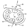
도 2를 참조하면, 패드 컨디셔너 조립체(32)가 본 개시내용의 실시예에 도시되어 있다. 패드 컨디셔너 조립체(32)는 기재 또는 이면 판(56)의 장착 면(54)에 고착된 컨디셔닝 세그먼트(52)를 포함하고, 장착 면(54)은 도 1의 동작 동안 연마 패드(38)에 인접한다. 일 실시예에서, 세그먼트(52)는 에폭시 같은 접착제를 사용하여 장착 면(54)에 결합된다. 각 컨디셔닝 세그먼트(52)는 도 1의 동작 동안 연마 패드(38)와 접촉하는 접촉 면(58)을 포함한다. 다양한 실시예에서, 이면 판(56)의 두께(62)는 경계값을 포함하여 0.05 내지 0.5 인치의 범위이고, 일부 실시예에서, 두께(62)는 경계값을 포함하여 0.05 내지 0.15 인치의 범위 이내이다. (여기서, "경계값 포함"으로 표시된 범위는 언급된 범위의 종점 값을 포함한다.) 2 , a
도 3a 내지 도 3c를 참조하면, 컨디셔닝 세그먼트(52a)가 본 개시내용의 일 실시예에서 제공되어 있다. 컨디셔닝 세그먼트(52a)는 컨디셔닝 세그먼트(52a)의 접촉 면(58)에 수직인 전방 방향(72)(도 2)으로 돌출하는 복수의 세장형 돌출부(70)를 포함하고, 이 세장형 돌출부(70)는 컨디셔닝 세그먼트(52a)와 단일체이다. 각 세장형 돌출부(70)는 폭(76)과 길이(78)를 형성하는 베이스(74)를 포함하고, 길이(78)는 폭(76)보다 크고, 세장형 돌출부(70)의 장축(80)을 형성한다(도 3c). 각 세장형 돌출부(70)는 세장형이며, 길이(78)와 실질적으로 정렬되는 적어도 하나의 융기부 라인(82)을 더 형성한다. 따라서, 각 융기부 라인(82)은 장축(80)의 방향으로 세장형이다. 다양한 실시예에서, 베이스 폭(76)에 대한 베이스 길이(78)의 비율은 경계값을 포함하여 2 내지 20의 범위이다. 일부 실시예에서, 이 비율은 경계값을 포함하여 2 내지 10의 범위이다. 일부 실시예에서, 이 비율은 경계값을 포함하여 2 내지 5의 범위이다. 베이스 폭(76)과 베이스 길이(78)의 치수의 비제한적인 예는 각각 150 μm과 500 μm이다.3A-3C , a
도시된 실시예에서, 복수의 세장형 돌출부(70)는 복수의 돌출부 클러스터(90)로 그룹화되고, 돌출부 클러스터는 사전결정된 패턴을 형성한다. 컨디셔닝 세그먼트(52a)에 대하여, 각 돌출부 클러스터(90)의 세장형 돌출부(70)는 "스타버스트" 클러스터(92a)로 배열되고, 여기서, 세장형 돌출부(70)의 장축(80)은 중앙 영역(86)으로부터 반경방향 외향 연장한다. 도 3c의 도면에 대하여, 스타버스트 클러스터(92a)는 중앙 영역(86) 둘레에 균등하게 회전방향으로 분포된 8개 세장형 돌출부(70)를 포함하고, 각 세장형 돌출부(70)는 수치 소수점 접미사(70.1 내지 70.8)로 식별된다. 다양한 실시예에서, 스타버스트 클러스터(92a)는 도 3a에 도시된 바와 같이 컬럼(94) 및 로우(96)의 매트릭스 배열로 배열된다. In the illustrated embodiment, the plurality of
도 4a 및 도 4b를 참조하면, 복수의 스타버스트 클러스터(92b)를 포함하는 컨디셔닝 세그먼트(52b)가 본 개시내용의 실시예의 대안적 배열로 도시되어 있다. 스타버스트 클러스터(92b)는 6개 세장형 돌출부(70)를 포함하고(스타버스트 클러스터(92a)에 대해 제공된 8개 대신), 세장형 돌출부(70)는 중앙 영역(86) 둘레로 회전방향으로 균등하게 분포되어 있다. 스타버스트 클러스터(92b)에 대하여, 각 세장형 돌출부(70b)는 수치 소수점 접미사(70.01 내지 70.06)로 식별된다. 다양한 실시예에서, 스타버스트 클러스터(92b)는 도 4a에 도시된 바와 같이 로우(98)에 실질적으로 수직인 지그재그 패턴(99)을 형성하도록 서로에 관하여 변위되어 있는 복수의 로우(98)를 제공하는 엇갈린 배열로 배열되어 있다. 복수의 컬럼이 서로에 관하여 변위되어 컬럼에 직교하는 지그재그 패턴(미도시)을 형성하는 엇갈린 배열도 고려된다. 4A and 4B , a conditioning segment 52b comprising a plurality of
컬럼(96) 및 로우(98)는 여기서 실질적으로 직선이며 서로 직교하는 것으로 도시되어 있음을 주의하여야 한다. 예를 들어, 이면 판(56)의 중심으로부터 알려진 반경에서 원호형 라인을 따르는 줄(row) 같은 다른 배열이 고려된다. 또한, 도시된 실시예에서, "컬럼"(96)은 이면 판(56)에 장착될 때 컨디셔닝 세그먼트(52)의 반경 방향과 실질적으로 정렬되는 것으로 도시되어 있다. 이러한 배열은 제한적인 것은 아니다. 즉, 컬럼(96) 및 로우(98)는 반경 방향에 관하여 선택된 각도로 대각선으로 배열될 수 있다.It should be noted that
스타버스트 클러스터(92a, 92b)의 스윕각(θ)은 예로서 스타버스트 클러스터(92a 또는 92b)의 각도 배향을 변경함으로써, 중앙 영역(86) 둘레에 균등 분포된 세장형 돌출부(70)의 수를 감소 또는 증가시킴으로써, 비균일 분포로 중앙 영역(86) 둘레에서 세장형 돌출부(70)를 분포시킴으로써 또는 그 조합에 의해 다양한 방식으로 변경될 수 있다는 것을 이해하여야 한다. The sweep angle θ of the
동작시, 패드 컨디셔너 조립체(32)는 예로서, 회전 방향(102)으로 회전된다(도 2, 도 3c 및 도 4b). 각 스타버스트 클러스터(92a, 92b)는 회전 방향(102)을 추종하며, 그래서, 각 세장형 돌출부(70)는 스윕각(θ)을 형성하고, 이 스윕각은 이동의 스윕 방향(104)과 각각의 세장형 돌출부(70)의 융기부 라인(82) 사이의 각도로서 취해진다. 스타버스트 배열로 인해, 다양한 스윕각(θ)이 제공된다. 예로서, 스타버스트 클러스터(92a)를 고려하면, 스윕각 θ1 (0°), θ2 (+45°), θ3 (90°) 및 θ4 (-45°)를 제공한다. 예로서, 스타버스트 클러스터(92b)를 고려하면, 스윕각 θ5 (+30°), θ6 (-30°) 및 θ3 (90°)를 제공한다.In operation, the
스타버스트 돌출부 클러스터(92a, 92b) 이외의 돌출부 클러스터(90)가 모두 도려된다. 예로서, 도 5를 참조하면, 복수의 컬럼형 클러스터(92c)를 포함하는 컨디셔닝 세그먼트(52c)가 본 개시내용의 일 실시예에 도시되어 있다. 도시된 컬럼형 클러스터(92c)는 스타버스트 클러스터(92a)와 동일한 다양한 스윕각(θ1 내지 θ4)을 제공하지만, 컬럼형 형태로 배열된 세장형 돌출부(70)를 갖는다. 컬럼형 클러스터(92c)는 또한 대안적으로 또는 추가적으로 스타버스트 클러스터(92b)의 스윕각(θ5, θ6)을 제공하도록 구성될 수도 있다. 컬럼형 클러스터(92c)가 컬럼형 배향인 것으로 도시되어 있지만, 컬럼형 클러스터가 로우로 또는 컬럼과 로우 배향의 혼합으로 배열되는 실시예도 고려된다.All of the protrusion clusters 90 other than the
예로서, 도 6을 참조하면, 복수의 선형 클러스터(92d)를 포함하는 컨디셔닝 세그먼트(52d)가 본 개시내용의 일 실시예에 도시되어 있다. 선형 클러스터(92d) 각각은 동일한 각도 배향으로 존재하는 복수의 세장형 돌출부(70)를 포함한다. 도시된 실시예에서, 선형 클러스터(92d)는 컬럼형 배열이며, 선형 클러스터(92d)의 혼합을 포함하는 주어진 컬럼을 가지고, 스타버스트 클러스터(92a)와 동일한 다양한 스윕각(θ1 내지 θ4)을 제공한다. 선형 클러스터(92d)는 또한 대안적으로 또는 추가적으로 스타버스트 클러스터(92b)의 스윕각(θ5, θ6)을 제공하도록 구성될 수도 있다. 선형 클러스터(92d)가 컬럼 배향으로 선형인 것으로 도시되어 있지만, 선형 클러스터가 로우 배향으로 또는 컬럼과 로우 배향의 혼합으로 존재하는 실시예도 고려된다.As an example, referring to FIG. 6 , a
컨디셔닝 세그먼트(52)의 혼합이 동일한 컨디셔너 조립체(32)에 사용되는 것이 고려된다. 예로서, 일 비제한적 실시예는 교번적 컨디셔닝 세그먼트(52a, 52b)의 혼합을 포함한다. 이런 배열은 임의의 하나의 컨디셔닝 세그먼트(52a 또는 52b) 단독보다 더 다양한 스윕각(θ)을 제공한다. 다른 실시예는 교번적 컨디셔닝 세그먼트(52c, 52d)의 혼합을 포함한다. 다양한 실시예는 모든 4가지 컨디셔닝 세그먼트(52a 내지 52d)의 혼합을 포함하며, 다른 실시예는 컨디셔닝 세그먼트(52a 내지 52d) 중 임의의 둘 또는 셋의 혼합을 포함한다.It is contemplated that a mix of
다양한 유형의 돌출부 클러스터(90)가 동일한 컨디셔닝 세그먼트(52)에 포함되는 것이 추가로 고려된다. 예로서, 일 실시예에서, 스타버스트 클러스터(92a, 92b)의 혼합이 동일 컨디셔닝 세그먼트(52)에 포함된다. 다른 실시예는 컬럼형과 선형의 혼합을 포함한다. 교번적 컨디셔닝 세그먼트(52a, 52b)에서와 같이, 이런 배열은 임의의 하나의 컨디셔닝 세그먼트(52a - 52d) 단독보다 더 다양한 스윕각(θ)을 제공한다. 다양한 실시예는 모든 4가지 돌출부 클러스터(92a 내지 92d) 같은 돌출부 클러스터(90)의 혼합을 포함한다. 다른 실시예는 돌출부 클러스터(92a 내지 92d) 중 단지 둘 또는 셋의 혼합을 포함한다. 단일 피크 돌출부(미도시)가 본 개시내용의 세장형 돌출부(70) 사이에 산재도는 것도 고려된다. It is further contemplated that different types of protrusion clusters 90 are included in the
기능적으로, 컨디셔닝 세그먼트(52a 내지 52d) 및 설명된 변형을 포함하는 상술한 실시예에 대하여, 세장형 돌출부(70)의 융기부 라인(82)과 조합한 다양한 스윕각(θ)은 연마 패드(38)의 피컨디셔닝 면(40)의 다면적 조작을 제공한다. 예로서, 컨디셔닝 세그먼트(52a)의 스타버스트 클러스터(92a)에 대하여, 주어진 스윕각(θ)(예를 들어, 도 3c의 세장형 돌출부(70.2, 70.6)의 스윕각(θ2))에서 연마 패드(38)의 표면을 가공하는 융기부 라인(82)은 다른 각도에서 스윕하는 융기부 라인(82)(예를 들어, 스윕각 θ1, θ3 및 θ4)과는 다른 방식으로 연마 패드(38)의 피컨디셔닝 면(40)을 굴곡시키는 경향이 있다. 컨디셔너 조립체(32)가 연마 패드(38)의 피컨디셔닝 면(40) 위에서 회전 및/또는 병진됨에 따라 피컨디셔닝 면(40) 상의 모든 지점이 일반적으로 다수의 스타버스트 클러스터(92a)에 의해 마삭되므로, 이들 지점 각각은 또한 상이한 스윕각(θ1 내지 θ4)에서 다수의 융기부 라인(82)에 의해 마삭되는 경향이 있다. (본 기술 분야의 숙련자는 동일한 내용이 컨디셔닝 세그먼트(52b, 52c 및 52d)와 상술한 변형에 대해서도 적용됨을 알 수 있을 것이다.)이는 융기부 라인(82)의 방향성 마삭 특성을 갖지 않는 단지 첨단부 마삭만을 발생시키는 경향의 종래의 CMP 패드 컨디셔너와는 대조적이다. Functionally, for the above-described embodiments including
피컨디셔닝 면(40)의 이런 다면적 조작은 컨디셔너 조립체(32)의 절삭율 및 CMP 프로세스로부터 잔류되는 연마 패드(38)의 공극 내의 이물의 제거를 향상시켜 연마 패드(38)의 공극을 더 양호하게 개방시키고 CMP 프로세스에서의 제거율을 더 양호하게 유지시킨다는 것을 발견하였다. 주상 돌출부를 갖는 종래의 컨디셔닝 패드에 비해 25%만큼 높은 절삭율의 증가가 관찰되었다.This multi-faceted manipulation of the conditioned
도 7 및 도 7a 내지 도 7c를 참조하면, 세장형 돌출부(70)를 위한 삼각 주상형 형상(120)이 본 개시내용의 실시예에 도시되어 있다. 삼각 주상형 형상(120)은 단부 모습 또는 단면 모습이 삼각형을 형성하기 때문에 이렇게 명명된다. 삼각 주상형 형상(120)은 폭(76) 및 길이(78)를 갖는 상술한 베이스(74), 융기부 라인(82)을 포함하고, 장축(80)을 형성한다. 삼각 주상형 형상(120)은 또한 높이(122)를 형성하고, 측부 면(124) 및 단부 면(126)을 추가로 제공한다. 베이스(74)는 면을 형성하지 않으며, 대신, 가상 경계(128)를 형성하고, 이 가상 경계를 가로질러 삼각 주상형 형상(120)은 컨디셔닝 세그먼트(52)와 단일체라는 것을 이해하여야 한다. 삼각 주상형 형상(120)의 융기부 라인(82)은 "우세" 융기부 라인(130)이며, 이는 융기부 라인(130)이 동일평면 최상위 에지와는 반대로 단일, 원위 또는 최상위 에지를 형성한다는 것을 의미한다.7 and 7A-7C , a triangular
도 8 및 도 8a 내지 도 8c를 참조하면, 세장형 돌출부(70)를 위한 오각 주상형 형상(140)이 본 개시내용의 실시예에 도시되어 있다. 오각 주상형 형상(140)은 단부 모습 또는 단면 모습이 오각형을 형성하기 때문에 이렇게 명명된다. 오각 주상형 형상(140)은 폭(76) 및 길이(78)를 갖는 상술한 베이스(74), 융기부 라인(82)을 포함하고, 장축(80)을 형성한다. 오각 주상형 형상(140)은 또한 높이(142)를 형성하고, 측부 면(144) 및 단부 면(146)을 추가로 제공한다. 베이스(74)는 면을 형성하지 않으며, 대신, 가상 경계(148)를 형성하고, 이 가상 경계를 가로질러 오각 주상형 형상(140)은 컨디셔닝 세그먼트(52)와 단일체라는 것을 이해하여야 한다. 오각 주상형 형상(140)의 융기부 라인(82)은 우세 융기부 라인(150)과 두 개의 "열세" 융기부 라인(152)을 포함하고, 열세 융기부 라인은 융기부 라인(152)이 우세 융기부 라인(150) 아래에 있다는 것(즉, 우세 융기부 라인(150)보다 이면 판(56)의 장착 면(54)에 더 근접하다는 것)을 의미한다. 8 and 8A-8C , a pentagonal
도 9 및 도 9a 내지 도 9c를 참조하면, 세장형 돌출부(70)를 위한 절두 주상형 형상(160)이 본 개시내용의 실시예에 도시되어 있다. 절두 주상형 형상(160)은 단부 모습 또는 단면 모습이 절두체를 형성하기 때문에 이렇게 명명된다. 절두 주상형 형상(160)은 폭(76) 및 길이(78)를 갖는 상술한 베이스(74), 융기부 라인(82)을 포함하고, 장축(80)을 형성한다. 절두 주상형 형상(160)은 또한 높이(162)를 형성하고, 측부 면(164) 및 단부 면(166)을 추가로 제공한다. 베이스(74)는 면을 형성하지 않으며, 대신, 가상 경계(168)를 형성하고, 이 가상 경계를 가로질러 절두 주상형 형상(160)은 컨디셔닝 세그먼트(52)와 단일체라는 것을 이해하여야 한다. 절두 주상형 형상(160)의 융기부 라인(82)은 우세 융기부 라인을 포함하지 않으며, 대신, 그 사이에 세장형 메사(172)가 형성되어 있는 최상위에 존재하는 동일평면에 있는 두 개의 융기부 라인(170)을 포함한다. 즉, 융기부 라인(170)은 공칭 바닥 기준 평면(238)으로부터 실질적으로 동일한 거리에 있다(도 11).9 and 9A-9C , a truncated
세장형 메사(172)는 장축(80)의 방향으로 세장형이고, 메사 폭(174)과 메사 길이(176)를 형성하며, 메사 길이(176)는 메사 폭(174)보다 더 크다. 다양한 실시예에서, 메사 폭(174)에 대한 메사 길이(176)의 비율은 경계값을 포함하여 2 내지 20의 범위이다. 일부 실시예에서, 이 비율은 경계값을 포함하여 2 내지 10의 범위이다. 일부 실시예에서, 이 비율은 경계값을 포함하여 2 내지 5의 범위이다.The elongate mesa 172 is elongate in the direction of the
주상형 형상(120, 140, 160)은 비제한적인 예로서 제공된다. 주상형 형상의 다른 단면, 예로서, 정사각형, 육각형 및 반원형이 고려된다. 융기부 라인으로서 식별될 수 있는 코너 에지를 고유하게 형성하지 않는 형상(예를 들어, 반원)에 대하여, 융기부 라인은 장축(80)에 수직인, 형상의 단면의 원위 말단 지점을 통과한다.Columnar shapes 120 , 140 , 160 are provided as non-limiting examples. Other cross-sections of columnar shapes are contemplated, eg square, hexagonal and semicircular. For shapes (eg, semicircles) that do not uniquely define a corner edge that can be identified as a ridge line, the ridge line passes through the distal end point of the cross-section of the shape, perpendicular to the
일 실시예에서, 세장형 돌출부는 실질적으로 균일한 높이로 이루어진다. 대안적으로, 하나 이상의 컨디셔닝 세그먼트(52)는 각 컨디셔닝 세그먼트(52) 내의 상이한 공칭 높이의 돌출부의 조합을 포함할 수 있다. 컨디셔닝 세그먼트(52)는 또한 각각 주어진 세그먼트 상에 실질적으로 균일한 돌출부 프로파일을 가질 수 있지만, 세그먼트들 사이에서는 다를 수 있다. 다른 실시예에서, 컨디셔닝 세그먼트(52)는 변하는 세장형 돌출부 프로파일의 상이한 조합을 가질 수 있다.In one embodiment, the elongate protrusions are of substantially uniform height. Alternatively, one or
여기에 예시된 다양한 패드 컨디셔너, 패드 컨디셔너 조립체 및 컨디셔닝 세그먼트는 그 크기나 영역이 제한되지 않으며, 예로서, 표준 4¼인치 직경 디스크 구성으로 형성될 수 있다. 일부 실시예에서, 이면 판(54)은 컨디셔닝 기기에 결합되고, 이면 판(54)은 약 2 내지 5 인치의 직경 범위의 디스크 형태이다. 물론, 다른 형상 및 크기가 패드 컨디셔너나 컨디셔닝 세그먼트를 위해 이면 판(54)으로서 사용될 수 있다. The various pad conditioners, pad conditioner assemblies, and conditioning segments illustrated herein are not limited in size or area, and may be formed of, for example, standard 4¼ inch diameter disc configurations. In some embodiments, backing
다양한 실시예에서, 컨디셔닝 세그먼트(52)는 실리콘, 실리콘 카바이드 및 실리콘 니트라이드 같은 세라믹 물질로 이루어진다. 세라믹 물질은 예로서, 베타 실리콘 카바이드이거나 베타 실리콘 카바이드를 포함하는 세라믹 물질일 수 있으며, 이는 분리된 탄소 페이즈와 잉여 탄소를 포함할 수 있다. In various embodiments,
일부 실시예에서, 다수의 형성 프로세스 중 하나를 사용하여 세장형 돌출부(70)/돌출부 클러스터(90)를 갖도록 텍스쳐형성되는, 근사 망상형 다공성 그라파이트 전구체로부터 패드 컨디셔너를 제조하는 방법이 구현된다. 텍스쳐형 그라파이트 기재는 본 기술 분야에 알려진 변환 기술을 사용하여 그후 근사 망상형 실리콘 카바이드 물질 기재로 변환될 수 있다. 근사 망상형 실리콘 카바이드는 베타 실리콘 카바이드일 수 있다. 여기서, "근사 망상형"은 최종 형상 및 공차를 달성하기 위해 최소의 프로세스 사후 기계가공을 수반하는 구성요소를 나타내기 위해 사용된다. 근사 망상형 다공성 그라파이트 전구체를 근사 망상형 실리콘 카바이드 물질로 변환함으로써 컨디셔닝 세그먼트(52)를 형성하는 것은 실리콘 카바이드를 직접적으로 텍스쳐형성하는 것에 비해 비용적 장점을 제공할 수 있으며, 그 이유는 실리콘 카바이드의 성형이 그 경도로 인해 시간 소모적인 프로세스이기 때문이다.In some embodiments, a method of making a pad conditioner from a near reticulated porous graphite precursor is implemented, which is textured to have
다른 실시예에서, 실리콘 카바이드 같은 경화된 기재가 직접적으로, 즉, 그라파이트의 텍스쳐형성 및 변환을 이용하지 않고, 텍스쳐형성된다. 직접적 텍스쳐형성은 세장형 돌출부(70)의 더 양호한 해상도를 제공할 수있다.In another embodiment, a cured substrate, such as silicon carbide, is textured directly, ie, without the use of texturing and transformation of graphite. Direct texturing may provide better resolution of the
일부 실시예에서, 처리된 또는 텍스쳐형성된 컨디셔닝 세그먼트(52)는 저 다공도(즉, 고밀도) 세라믹, 예컨대, 고밀도 실리콘 카바이드로 이루어진다. 일부 실시예에서, 실리콘 카바이드는 반응 결합된 실리콘 카바이드 물질이고, 여기서, 반응 결합된 실리콘 카바이드는 공극 구조 내로 실리콘이 침투되어 있는 소결된 알파 실리콘 카바이드 분말체이다. 이 프로세스는 특히 텍스쳐형성된 컨디셔닝 세그먼트(52)의 표면에서 최종 처리된 컨디셔닝 세그먼트(52)의 다공도를 감소시키는 경향이 있다.In some embodiments, treated or
다른 실시예에서, 컨디셔닝 세그먼트(52)의 다공도는 상당하다. 다양한 실시예에서, 세라믹 컨디셔닝 요소(52)의 다공도는 경계값을 포함하여 10% 내지 70%의 범위이고, 일부 실시예에서, 다공도는 경계값을 포함하여 0.2% 내지 30%이며, 일부 실시예에서, 다공도는 경계값을 포함하여 2% 내지 20%이다. In other embodiments, the porosity of the
근사 망상형 실리콘 카바이드로 변환되는 근사 망상형 그라파이트는 월드 와이드 웹 URL: www.poco.com/ AdditionalInformation/Literature/ProductLiterature/SiliconCarbide/tabid/194/Default.aspx (2015년 3월 18일 최종 방문)로부터 입수할 수 있는 "Properties and Characteristics of Silicon Carbide" A.H. Rashed 편저, 2002, Poco Graphite Inc. 텍사스주 데카투어 소재("Poco 참조문헌")에 개시된 방법 및 재료에 의해 형성될 수 있으며, 상기 문헌의 내용은 본 명세서에 포함되어 있는 특수한 정의를 제외하면 그 전문이 참조로 본 명세서에 통합되어 있다. Poco 참조문헌은 SiC 물질인 SUPERSIC-1의 특성을 통상적으로 20.5%의 총 다공도에 대하여 19%의 평균 개방 다공도 및 2.5%의 평균 폐쇄 다공도를 갖는 것으로서 개시하고 있다(Poco 참조문헌 7쪽). SUPERSIC-1도 기재를 위한 전구체로서 사용될 수 있다. 예로서, 돌출부는 근사 망상형 기재를 형성하도록 광-마삭 프로세스에 의해 SUPERSIC-1 기재에 형성된다. 실리콘 카바이드는 또한 SUPERSIC 또는 SUPERSIC-3C를 포함하고, 이들은 역시 텍사스주 데카투어 소재의 Poco Graphite로부터 입수할 수 있다. 근사 망상형 실리콘 카바이드로 변환될 수 있는 근사 망상형 기재를 위한 그라파이트가 또한 Poco Graphite로부터 얻어질 수 있다.Near-reticular graphite converted to near-reticular silicon carbide is from the World Wide Web URL: www.poco.com/AdditionalInformation/Literature/ProductLiterature/SiliconCarbide/tabid/194/Default.aspx (last visited March 18, 2015) "Properties and Characteristics of Silicon Carbide" AH available Edited by Rashed, 2002, Poco Graphite Inc. may be formed by the methods and materials disclosed in Decatur, Texas ("Poco Reference"), the contents of which are hereby incorporated by reference in their entirety, except for specific definitions contained herein, in their entirety. have. The Poco reference discloses the properties of SUPERSIC-1, a SiC material, as having an average open porosity of 19% and an average closed porosity of 2.5% for a total porosity of typically 20.5% (Poco Reference page 7). SUPERSIC-1 can also be used as a precursor for the substrate. As an example, the protrusions are formed in the SUPERSIC-1 substrate by a photo-abrasive process to form a near reticulated substrate. Silicon carbide also includes SUPERSIC or SUPERSIC-3C, which is also available from Poco Graphite, Decatur, TX. Graphite for a near-reticular substrate that can be converted to a near-reticular silicon carbide can also be obtained from Poco Graphite.
다양한 실시예에 사용되는 실리콘 카바이드 및 근사 망상형 그라파이트와 실리콘 카바이드 전구체는 다공성 및 고밀도 실리콘 카바이드를 포함하고, 이들은 부분적으로 또는 전체적으로 Rashed 등의 미국 특허 제7,799,375호에 개시된 방법 및 물질을 사용하여 형성될 수 있고, 상기 특허의 내용은 본 명세서에 포함된 특정한 정의를 제외하면 그 전문이 본 명세에 참조로 통합되어 있다. Rashed는 개방 다공도를 갖는 다공성 실리콘 카바이드 예비성형체가 제공된다. 개방 다공도는 바람직하게는 약 10% 내지 약 60%의 범위이다"(Rashed, 컬럼 5, 44-46줄)라고 개시하고 있으며, 18-19%, 0.3%, 0.2% 및 2.3%의 개방 다공도의 특정 예가 표 1에 나열되어 있다(Rashed, 컬럼 7, 36-50줄). 일 예에서, Poco Graphite로부터의 다공성 그라파이트 기재는 다공성 그라파이트를 다공성 실리콘 카바이드 기재로 변환하기 위해 실리콘 모노옥사이드 가스의 존재 하에 1800℃로 가열될 수 있다. 따라서, 일부 실시예에서, 돌출부를 갖는 근사 망상형 다공성 그라파이트 기재는 근사 망상형 다공성 그라파이트를 근사 망상형 다공성 실리콘 카바이드로 변환하기 위해 실리콘 모노옥사이드의 존재 하에 1800℃로 가열될 수 있다. Silicon carbide and near-reticular graphite and silicon carbide precursors used in the various embodiments include porous and high-density silicon carbide, which may be formed in part or in whole using the methods and materials disclosed in U.S. Patent No. 7,799,375 to Rashed et al. , the content of which is incorporated herein by reference in its entirety, except for specific definitions contained herein, in its entirety. Rashed provides porous silicon carbide preforms with open porosity. The open porosity preferably ranges from about 10% to about 60%” (Rashed, col. 5, lines 44-46), with an open porosity of 18-19%, 0.3%, 0.2% and 2.3%. Specific examples are listed in Table 1 (Rashed, column 7, lines 36-50) In one example, a porous graphite substrate from Poco Graphite was prepared in the presence of silicon monoxide gas to convert the porous graphite to a porous silicon carbide substrate. It can be heated to 1800° C. Thus, in some embodiments, a near-reticular porous graphite substrate having protrusions is heated to 1800° C. in the presence of silicon monoxide to convert the near-reticular porous graphite to near-reticular porous silicon carbide. can be heated.
컨디셔닝 기재 또는 세그먼트(52) 상에 세장형 돌출부(70)를 형성하기 위해 다수의 제조 방법이 본 기술 분야의 숙련자들에게 알려져 있다. 그라파이트 또는 실리콘 카바이드 기재의 표면 상에 세장형 돌출부(70)를 형성하는 방법의 비제한적 예는 와이어 전기 방전 기계가공(EDM), 마스크식 마삭 기계가공, 수류 제트 기계가공, 광 마삭 기계가공, 레이저 기계가공 및 통상적 밀링을 포함한다. 예시적 기계가공 기술은 Matsumura 등의 미국 특허 출원 제2006/0055864호와 Menor 등의 PCT 공보 제WO/2011/130300호에 개시되어 있으며, 이들의 내용은 본 명세서에 포함된 특정한 정의를 제외하면 본 명세서에 그 전문이 참조로 통합되어 있다. A number of manufacturing methods are known to those skilled in the art for forming
다양한 실시예에서, 다공성 물질의 공극 크기는 경계값을 포함하여 2-60 μm의 범위이고, 일부 실시예에서, 공극 크기는 경계값을 포함하여 20-50 μm의 범위이고, 일부 실시예에서, 공극 크기는 경계값을 포함하여 5-50 μm의 범위이고, 일부 실시예에서, 공극 크기는 경계값을 포함하여 5-30 μm의 범위이다.In various embodiments, the pore size of the porous material is in the range of 2-60 μm including the boundary value, in some embodiments, the pore size is in the range of 20-50 μm including the boundary value, and in some embodiments, The pore size is in the range of 5-50 μm inclusive of the threshold, and in some embodiments, the pore size is in the range of 5-30 μm inclusive of the boundary value.
도 10을 참조하면, 다공성 기재의 기계가공에 의해 생성된 결과적인 주상형 돌출부(202)의 레이저 공초점 현미경 이미지(200)(이하, "현미경사진"(200))가 본 개시내용의 일 실시예에 도시되어 있다. 현미경사진(200)은 도 3a 및 도 3b에서 발견되는 것 같이 스타버스트 클러스터(92a)를 보여준다. 현미경사진의 세장형 돌출부(70)는 도 3c에서의 접미사 약속에 따라 참조번호 202.1 내지 202.8에 의해 개별적으로 식별된다. 결과적인 융기부 라인(204) 및 결과적인 에지(206)가 또한 현미경사진(200)에 나타나 있다. 결과적 주상형 돌출부(202)의 코너와 결과적 에지(206)는 날카롭고 잘 규정되어 있는 대신 모따기가공되거나 둥글게 나타난다.Referring to FIG. 10 , a laser confocal microscopy image 200 (hereinafter “micrograph” 200) of the resulting
컨디셔닝 세그먼트(52)의 공극 크기 및 다공도는 결과적 주상형 돌출부(202)의 정의의 한 가지 인수이다. 예로서, 주어진 주상형 형상을 제공하기 위한 컨디셔닝 세그먼트(52)의 텍스쳐형성은 공극의 보이드를 노출시키는 경향이 있고, 그래서, 주상형 형상(120, 140, 160)의 단부 면(126, 146, 166) 및 측부 면(124, 144, 164)은 포켓형 또는 조면화된 텍스쳐를 취하게 된다. 노출된 공극은 또한 현미경사진(200)의 세장형 돌출부(202.5, 202.6)에서 가장 잘 볼 수 있는 바와 같이 주상형 형상(120, 140, 160)의 에지와 다른 코너 및 융기부 라인(82)에 불규칙성 및 어긋남(jaggedness)을 유발할 수 있다. 도 10은 또한 현미경사진(200) 상의 결과적 세장형 돌출부(202.2, 202.3, 202.4) 상으로 삼각 주상형 형상(120)을 윤곽형성함으로써 이상적 삼각 주상형 형상(120)으로부터의 편차를 정성적으로 예시하고 있다.The pore size and porosity of the
따라서, 소위 "주상형" 형상(120, 140 및 160)은 도 10에 예시된 바와 같이 실제 결과적 형상의 상세한 설명 대신 결과적 형상의 원하는 윤곽으로서 더 많은 역할을 하는 이상적 또는 소망적 형상을 설명한다. 도 10의 설명은 윤곽으로서의 역할을 하는 이상적 또는 소망적 삼각 주상형 형상(120)과 결과적 삼각 주상형 형상(200a)의 결과적인 노출된 에지 및 코너를 정성적으로 예시하고 있다. 다공도 및 공극 크기가 더 클수록, 실제 또는 결과적 형상이 이상으로부터 벗어나는 편차는 더 커진다. 일반적으로, 기계가공 기술도 이상적 형상으로부터의 편차에 기여하며, 특정 기술은 다른 기술보다 조면도에 더 많이 기여하지만, 다공도 및 공극 크기가 증가함에 따라, 이상적 주상형 형상으로부터의 결과적 편차는 형성 또는 기계가공 기술에 점점더 무관해지게 된다.Thus, the so-called “columnar” shapes 120, 140 and 160 describe an ideal or desired shape that serves more as a desired contour of the resulting shape instead of a detailed description of the actual resulting shape, as illustrated in FIG. 10 . The description of FIG. 10 qualitatively illustrates the resulting exposed edges and corners of the ideal or desired triangular
여기서, "윤곽에 따른" 형상의 형성은 안정한, 비다공성 물질(예컨대 금속)로 윤곽형성된 형상을 얻을 수 있는 형성 작업을 수행하는 것을 의미한다. "윤곽에 따른" 형성은 최종 형성된 형상이 반드시 윤곽의 사양을 충족하는 것을 의미하지 않으며, 대신, 결과적 형상이 기재 물질의 다공도에 연계한 윤곽으로부터의 변화 및 이탈을 포함하는 것을 의미한다. 따라서, 도 10의 결과적 주상형 돌출부(202)는 이들이 따르고자 하는 이상적 삼각 주상형 형상(120)의 윤곽을 정확히 규정하지 않으며, 삼각 주상형 형상(120)의 "윤곽에 따른" 결과적 주상형 돌출부(202)를 형성한 결과이다.Here, the formation of a shape "according to the contour" means carrying out a forming operation which can obtain the contoured shape from a stable, non-porous material (eg metal). Forming “according to the contour” does not mean that the final formed shape necessarily meets the specifications of the contour, but instead means that the resulting shape includes variations and departures from the contour that are linked to the porosity of the substrate material. Thus, the resulting
다공성 기재에 의해 제공되는 포켓형 텍스쳐는 일반적으로 연마 패드의 컨디셔닝을 위해 유리하다. 다양한 실시예에서, 포켓형 텍스쳐의 효과는 특히, 더 높은 다공도 및 더 큰 공극 크기를 갖는 기재에 대해 초연마 그릿과 유사한 조면도를 생성한다. 일부 실시예에서, 기계가공된 다공성 물질은 코팅 적용 이후 어떠한 샘플링 길이도 고려되지 않을 때 경계값을 포함하여 0.5 μm 내지 10 μm의 범위, 그리고, 8 μm 샘플링 길이를 고려할 때 경계값을 포함하여 0.05 μm 내지 1.0 μm의 범위의 평균 자승근 조면도를 생성한다. 여기서, "샘플링 길이"는 조면도 데이터가 축적되는 길이이다.The pocketed texture provided by the porous substrate is generally advantageous for conditioning the polishing pad. In various embodiments, the effect of pocketed texturing produces a roughness similar to superabrasive grit, especially for substrates with higher porosity and larger pore size. In some embodiments, the machined porous material ranges from 0.5 μm to 10 μm including the threshold when no sampling length is considered after application of the coating, and 0.05 including the threshold when considering an 8 μm sampling length. Generate root-mean roughness in the range of μm to 1.0 μm. Here, the "sampling length" is the length at which the roughness data is accumulated.
도 10a를 참조하면, 결과적 주상형 돌출부(202)의 가상 단면도(190)가 본 개시내용의 일 실시예에서 제공되어 있다. 단면도(190)는 또한 점선으로 도시된 삼각 주상형 형상(120)의 윤곽을 포함하며, 이는 현미경사진(200)의 주상형 돌출부(202)의 이상적 또는 소망적 프로파일을 구성한다. 일부 실시예에서, 컨디셔닝 세그먼트(52)의 다공도에 의해 유발되는 불규칙성 및 기계가공 프로세스의 변화는 불규칙 프로파일(192)을 생성한다. 불규칙 프로파일(192)은 상술한 어긋남을 특징으로 한다. 또한, 도시된 실시예에서, 불규칙성은 결과적 융기부 라인(202)이 둥근 프로파일(194)을 형성하게 한다.Referring to FIG. 10A , a virtual
둥근 융기부 라인은 아래에서 도 12a 내지 도 12c에 예시된 것 같이 기계가공 프로세스의 고의적 생성물일 수 있다는 것을 추가로 유의하여야 한다. It should be further noted that the rounded ridge line may be an intentional product of a machining process as illustrated in FIGS. 12A-12C below.
도 11을 참조하면, 세장형 돌출부(70)의 높이의 변동에 대한 결과적 융기부 라인(202) 상의 어긋남의 영향이 본 개시내용의 일 실시예에서 도시되어 있다. 그와 일체이면서 전방 방향(216)으로 연장하는 세장형 돌출부의 제1 및 제2 사전결정된 서브세트(212, 214)를 갖는 기재(210)가 본 개시내용의 일 실시예에서 도시되어 있다. "세장형 돌출부의 사전결정된 서브세트"는 예로서, 컨디셔닝 세그먼트(52)의 접촉 면(58) 상의 좌표 위치 또는 돌출부 클러스터(90) 내의 상대적 위치에 의한 정위에 의해 식별되는 세장형 돌출부의 서브세트이다. Referring to FIG. 11 , the effect of the misalignment on the resulting
세장형 돌출부의 제1 사전결정된 서브세트(212)는 도 8에 윤곽형성된 것 같은 결과적 오각 주상형 형상의 측단면 모습이고, 세장형 돌출부의 제2 사전결정된 서브세트(214)는 도 7에 윤곽형성되고 도 10에 도시된 것 같은 결과적 삼각 주상형 형상의 측단면 모습이다. 본 실시예에서, 돌출부의 제1 사전결정된 서브세트(212)는 공칭적으로 하나의 평균 높이(H1)에 있고, 돌출부의 제2 사전결정된 서브세트(214)는 공칭적으로 제2 평균 높이(H2)에 있으며, 평균 높이(H1)는 평균 높이(H2)보다 크다. "전방 방향"(216)은 기재(210)의 전방 표면 또는 "바닥"(218)에 실질적으로 수직이면서 그로부터 멀어지는 방향이다. 공칭적으로 더 큰 높이의 돌출부의 제1 사전결정된 서브세트(212)는 본 명세서에서 달리 "주 돌출부"라 지칭된다. 공칭적으로 더 낮은 높이의 돌출부의 제2 사전결정된 서브세트(214)는 달리 "부 돌출부"라 지칭된다.A first predetermined subset of
제1 및 제2 사전결정된 서브세트(212, 214)의 돌출부 각각은 원위 말단부(215)를 갖는 것을 특징으로 할 수 있다. 돌출부의 제1 사전결정된 서브세트(212)는 제1 정합 평면(222)의 제1 변동(220) 내에 있는 원위 말단부(215)를 가질 수 있고, 제1 정합 평면(222)은 실질적으로 전방 표면(218)에 평행하다. 여기서, "변동"은 돌출부의 사전결정된 서브세트의 최고위 및 최저위 원위 말단부 사이의 높이 편차로서 정의되며, 높이는 정합 평면에 대한 수직으로서 규정된다. 일 실시예에서, 돌출부의 제1 사전결정된 서브세트(212)는 서로에 대해 고정된 사전결정된 관계에서 제1 정합 평면(222)에 인접하게 위치된다.Each of the protrusions of the first and second
돌출부의 제2 사전결정된 서브세트(214)는 제2 정합 평면(228)의 제2 변동(226) 내에 있는 원위 말단부(215)를 포함하며, 제2 정합 평면(228)은 전방 표면(218)에 실질적으로 평행하고, 돌출부의 제2 사전결정된 서브세트(214)는 서로에 대해 고정된 사전결정된 관계로 제2 정합 평면(228) 상에 위치된다. The second
제1 및 제2 정합 평면(222, 228)은 또한 각각 "상부" 및 "하부" 정합 평면이라고도 지칭되며, "상부"는 기재(210)의 바닥(218)으로부터 가장 먼 위치에 있다는 것을 의미한다. 돌출부의 제1 사전결정된 서브세트(212)는 제2("하부") 정합 평면(228)을 통해 연장한다. The first and second mating planes 222 , 228 are also referred to as “upper” and “lower” mating planes, respectively, where “upper” means at a position furthest from the
제1 정합 평면(222)은 오프셋 거리(232) 만큼 전방 방향(216)으로 제2 정합 평면(228)으로부터 공칭적으로 오프셋되는 것으로서 특징지어질 수 있다. 특정 실시예에서, 오프셋 거리(232)는 도 12에 도시된 바와 같이 제1 변동(220) 또는 제2 변동(226)보다 크다. 오프셋 거리(232)는 고정된 치수 또는 치수 범위보다 큰 것으로 특징지어질 수 있거나, 변동(220 또는 226) 중 어느 하나의 배수 또는 인수보다 큰 것으로서 특징지어질 수 있다. 전형적인, 그리고, 비제한적인 변동(220, 226)의 치수 범위는 5 μm 내지 50 μm이다. 일부 실시예에서, 변동(220, 226)은 10 μm 내지 25 μm의 범위일 수 있다. 변동(220, 226)은 또한 최소값보다 크고, 최대값보다 작은 것으로 특징지어질 수 있다. 오프셋 거리(232)를 위한 변동(220, 226)의 통상적인, 그리고, 비제한적인 배수 또는 인수는 1 또는 2보다 크다. 오프셋 거리(232)를 위한 통상적인 그리고 비제한적인 값은 경계값을 포함하여 10 μm 내지 80 μm의 범위이다.The
다른 실시예에서, 오프셋 거리(232)는 제1 변동(220) 및 제2 변동(226) 중 하나 또는 양자 모두보다 작다(미도시). 즉, 도 12의 예에서, 돌출부의 제1 사전결정된 서브세트(212)의 돌출부 중 일부는 생각건대 이들이 더 큰 평균 높이(H1)를 갖는 돌출부의 제1 사전결정된 서브세트(212)에 속하기는 하지만 돌출부의 제2 사전결정된 서브세트(214)의 제2 평균 높이(H2) 미만인 원위 말단부(215)를 가질 수 있다. 유사하게, 돌출부의 제2 사전결정된 서브세트(214)의 돌출부 중 일부는 생각건대 이들이 더 작은 평균 높이(H2)를 갖는 돌출부의 제2 사전결정된 서브세트(214)에 속하기는 하지만 돌출부의 제1 사전결정된 서브세트(212)의 제1 평균 높이(H1) 보다 큰 원위 말단부(215)를 가질 수 있다. In another embodiment, the offset
일 실시예에서, 돌출부의 각각의 제1 및 제2 사전결정된 서브세트(212, 214)의 제1 및 제2 평균 높이(H1, H2)는 평균 "정과 골사이의" 높이이다. 돌출부의 정점과 골 사이의 높이는 공칭 바닥 기준 평면(238)과 원위 말단부(215) 사이의 평균 거리로서 정의된다. 공칭 바닥 기준 평면(238)은 바닥(218)의 중간 레벨을 통과하는 평면이다. 컨디셔닝 세그먼트(52)의 다공도는 비균등 기계가공된 표면을 초래할 수 있으며, 그래서, 바닥(218)은 높은 정도의 조면도 및 무작위성을 소유할 수 있어서 중간 레벨을 결정하기 어렵게 할 수 있다. 따라서, 돌출부의 평균 정점과 골 사이의 높이를 특징짓는 한 가지 방식은 주 돌출부를 위한 최소 평균 정점과 골 사이의 높이와 부 돌출부를 위한 최대 평균 정점과 골 사이의 높이를 형성하는 것이다. 이런 특성화는 바닥 기준 평면(238)의 정위에 관하여 높은 수준의 불확실성을 허용할 수 있다. 특성화의 다른 방법은 Smith 등의 국제 특허 출원 공보 제WO 2012/122186에 개시된 것 같이, 각 돌출부의 "도드라진 높이"를 결정하는 것이다.In one embodiment, the first and second average heights H1 , H2 of each of the first and second
도 12a 내지 도 12c를 참조하면, 초연마 그릿 입자(262)를 사용하는 다양한 세장형 돌출부(260a, 260b, 260c) 각각의 단면도가 본 개시내용의 실시예에서 도시되어 있다. (세장형 돌출부(260a, 260b, 260c)는 여기서 총체적으로 또는 전체적으로 세장형 돌출부(260)라 지칭된다). 일 실시예에서, 초연마 그릿 입자(262)는 다이아몬드 입자를 포함한다. 초연마 그릿 입자는 에폭시 같은 결합제를 사용하여 세장형 돌출부(260)에 고정될 수 있다. 다양한 실시예에서, 세장형 돌출부(260)는 상술한 컨디셔닝 세그먼트(52)에 대하여 설명한 것 같은 다공성 기재로부터 제조된다. 또한, 일부 실시예에서, 초연마 그릿 입자(262)는 CVD 다이아몬드 같은 경질이면서 내구성있는 코팅(264)으로 코팅된다.12A-12C , cross-sectional views of each of the various elongate protrusions 260a , 260b , 260c using
세장형 돌출부(260)의 단면 각각은 반경가공된 또는 둥근 또는 반경가공된 융기부 라인(267)과 기부 폭(266)을 형성하는 베이스(265)를 포함하며, 높이(268)는 베이스(265)와 반경가공된 융기부 라인(267) 사이에서 형성된다. 세장형 돌출부(260a, 260b, 260c) 각각은 베이스 폭(266)에 대한 높이(268)의 비율로서 규정되는 고유한 "형상비"를 갖는 것을 특징으로 한다. 다양한 실시예에서, 주어진 세장형 돌출부의 형상비는 경계값을 포함하여 0.5 내지 5의 범위이고, 일부 실시예에서, 경계값을 포함하여 0.5 내지 3의 범위이며, 일부 실시예에서, 경계값을 포함하여 1 내지 3의 범위이다.Each cross-section of the elongate protrusion 260 includes a base 265 defining a radiused or rounded or radiused
기능적으로, 결과적 조면화된 표면은 초연마 그릿 입자(262)의 계류(harboring)를 도와 결합제가 더 효과적이 될 수 있게 한다. 초연마 그릿 입자(262). 형상비는 세장형 돌출부(260)의 절삭율에 정성적으로 영향을 준다. 더 날카로운 돌출부 프로파일(즉, 더 높은 형상비를 갖는 세장형 돌출부 단면)은 더 둥근 돌출부 프로파일(즉, 더 낮은 형상비를 갖는 세장형 돌출부 단면)보다 더 침해적인 절삭율을 생성하는 경향이 있다.Functionally, the resulting roughened surface aids in harboring the
여기에 개시된 추가적 도면 및 방법 각각은 별개로 사용될 수 있거나, 다른 특징 및 방법과 연계하여 동일한 바를 형성 및 사용하기 위한 개선된 장치 및 방법을 제공할 수 있다. 따라서, 본 명세서에 개시된 특징 및 방법의 조합은 그 가장 넓은 개념에서 본 개시내용을 실시하는 것을 필요로 하지 않을 수 있으며, 대신, 단지 대표적이고 양호한 실시예를 특정하게 설명하는 것일 수 있다. Each of the additional figures and methods disclosed herein may be used separately or in connection with other features and methods may provide improved apparatus and methods for making and using the same bar. Accordingly, combinations of features and methods disclosed herein may not require practice of the disclosure in its broadest sense, but rather may merely be illustrative of a specific and preferred embodiment.
본 개시내용을 읽으면 본 기술 분야의 숙련자는 실시예에 대한 다양한 변형을 명백히 알 수 있다. 예로서, 관련 기술 분야의 숙련자는 상이한 실시예를 위해 설명된 다양한 특징이 단독으로 또는 상이한 조합으로 다른 특징과 적절히 조합, 조합해제 및 재조합될 수 있다는 것을 알 수 있다. 유사하게, 상술한 다양한 특징은 예시적 실시예에 관한 것이며 본 개시내용의 개념 및 범주에 대한 제한이 아니다. Various modifications to the embodiments will become apparent to those skilled in the art upon reading this disclosure. By way of example, those skilled in the art will appreciate that various features described for different embodiments may be suitably combined, decombined, and recombined with other features, alone or in different combinations. Similarly, the various features described above are directed to example embodiments and are not limitations on the concept and scope of the present disclosure.
관련 기술의 통상적 숙련자는 다양한 실시예가 상술한 임의의 개별 실시예에 예시된 것보다 소수의 특징을 포함할 수 있음을 알 수 있을 것이다. 본 명세서에 설명된 실시예는 다양한 특징이 조합될 수 있는 방식의 전부를 표현하는 것을 의도하지는 않는다. 따라서, 실시예는 상호 배제적 특징의 조합이 아니며, 대신, 청구범위는 본 기술분야의 통상의 숙련자가 이해하는 바와 같이 상이한 개별 실시예로부터 선택된 상이한 개별적 특징의 조합을 포함할 수 있다.Those of ordinary skill in the relevant art will appreciate that various embodiments may include fewer features than illustrated in any individual embodiment described above. The embodiments described herein are not intended to represent all of the ways in which various features may be combined. Thus, embodiments are not mutually exclusive combinations of features, but instead, the claims may include combinations of different individual features selected from different individual embodiments, as will be understood by one of ordinary skill in the art.
상술한 문헌의 참조에 의거한 임의의 통합은 본 명세서의 명시적 개시내용에 상반되는 어떠한 주제도 통합되지 않도록 제한된다. 상술한 문헌의 참조에 의거한 임의의 통합은 해당 문헌에 포함된 어떠한 청구항도 본 명세서에서 참조에 의해 통합되지 않도록 추가로 제한된다. 상술한 문헌의 참조에 의거한 임의의 통합은 해당 문헌에 제공된 임의의 정의가 본 명세서에 달리 명시적으로 포함되지 않는 한 본 명세서에 참조로 통합되지 않도록 추가로 제한된다.Any incorporation by reference of the foregoing documents is limited so as not to incorporate any subject matter that is contrary to the express disclosure herein. Any incorporation by reference of the aforementioned documents is further limited such that no claims incorporated therein are incorporated herein by reference. Any incorporation by reference of any of the foregoing documents is further limited such that any definitions provided in that document are not incorporated by reference herein unless expressly incorporated herein by reference.
본 명세서에 포함된 "실시예(들)", "개시내용", "본 개시내용", "개시내용의 실시예(들)", "개시된 실시예(들)" 및 유사표현은 승인된 종래 기술이 아닌, 본 특허 출원의 명세서(청구항과 도면을 포함하는 텍스트)를 언급한다."Embodiment(s)," "disclosure," "present disclosure," "embodiment(s) of the disclosure," "disclosed embodiment(s)," and similar expressions included herein Reference is made to the specification (text, including claims and drawings) of this patent application, not the description.
청구항의 해석의 목적상, 명백히, 특정 용어 "~를 위한 수단" 또는 "~를 위한 단계"가 각각의 청구항에 기재되어 있지 않은 한 35 U.S.C. 112(f)의 규정이 행사되지 않는 것을 의도한다.For purposes of interpreting claims, expressly, unless the specific term "means for" or "step for" is recited in the respective claim, 35 U.S.C. It is intended that the provisions of 112(f) will not be exercised.
Claims (35)
전방 표면 및 그와 일체인 복수의 세장형 돌출부를 포함하는 기재를 포함하고, 상기 복수의 세장형 돌출부 각각은 상기 전방 면과 실질적으로 평행한 장축을 형성하고, 상기 복수의 세장형 돌출부 각각은 상기 장축의 방향으로 연장하는 적어도 하나의 융기부 라인을 포함하며, 상기 복수의 세장형 돌출부는 상기 전방 표면에 수직인 전방 방향으로 돌출하며,
상기 복수의 세장형 돌출부 각각의 상기 장축은 상기 기재의 스윕 방향에 관하여 적어도 두 개의 각도 중 하나를 형성하고,
상기 복수의 세장형 돌출부는 복수의 클러스터로 그룹화되고, 상기 복수의 클러스터 각각은 사전결정된 패턴을 형성하는 상기 복수의 세장형 돌출부 중 둘 이상을 포함하는, CMP 컨디셔닝 세그먼트.chemical mechanical planarization (CMP) conditioning segment,
a substrate comprising a front surface and a plurality of elongate protrusions integral therewith, each of the plurality of elongate protrusions defining a major axis substantially parallel to the front face, each of the plurality of elongate protrusions having at least one line of ridges extending in the direction of the major axis, wherein the plurality of elongated projections project in a forward direction perpendicular to the front surface;
the long axis of each of the plurality of elongate protrusions forms one of at least two angles with respect to the sweep direction of the substrate;
wherein the plurality of elongate protrusions are grouped into a plurality of clusters, each cluster comprising at least two of the plurality of elongate protrusions forming a predetermined pattern.
상기 기재를 제공하는 것, 및
주상형 형상의 윤곽에 따라 상기 복수의 세장형 돌출부를 형성하는 것을 포함하는, 방법.A method of making the CMP conditioning segment of claim 1 or 3, the method comprising:
providing the above description, and
and forming the plurality of elongate protrusions according to the contour of the columnar shape.
Applications Claiming Priority (3)
| Application Number | Priority Date | Filing Date | Title |
|---|---|---|---|
| US201461968846P | 2014-03-21 | 2014-03-21 | |
| US61/968,846 | 2014-03-21 | ||
| PCT/US2015/021679 WO2015143278A1 (en) | 2014-03-21 | 2015-03-20 | Chemical mechanical planarization pad conditioner with elongated cutting edges |
Publications (2)
| Publication Number | Publication Date |
|---|---|
| KR20160136404A KR20160136404A (en) | 2016-11-29 |
| KR102304574B1 true KR102304574B1 (en) | 2021-09-27 |
Family
ID=54145367
Family Applications (1)
| Application Number | Title | Priority Date | Filing Date |
|---|---|---|---|
| KR1020167029446A KR102304574B1 (en) | 2014-03-21 | 2015-03-20 | Chemical mechanical planarization pad conditioner with elongated cutting edges |
Country Status (6)
| Country | Link |
|---|---|
| US (1) | US10293463B2 (en) |
| JP (1) | JP6542793B2 (en) |
| KR (1) | KR102304574B1 (en) |
| CN (1) | CN106463379B (en) |
| TW (1) | TWI666091B (en) |
| WO (1) | WO2015143278A1 (en) |
Families Citing this family (15)
| Publication number | Priority date | Publication date | Assignee | Title |
|---|---|---|---|---|
| US10105812B2 (en) * | 2014-07-17 | 2018-10-23 | Applied Materials, Inc. | Polishing pad configuration and polishing pad support |
| KR102040144B1 (en) * | 2016-01-08 | 2019-11-04 | 반도 카가쿠 가부시키가이샤 | Abrasive |
| KR102365066B1 (en) * | 2016-04-06 | 2022-02-18 | 엠 큐브드 테크놀로지스 | Diamond Composite CMP Pad Adjuster |
| US10471567B2 (en) * | 2016-09-15 | 2019-11-12 | Entegris, Inc. | CMP pad conditioning assembly |
| US20180085891A1 (en) * | 2016-09-29 | 2018-03-29 | Rohm And Haas Electronic Materials Cmp Holdings, Inc. | Apparatus for shaping the surface of chemical mechanical polishing pads |
| TWI621503B (en) * | 2017-05-12 | 2018-04-21 | Kinik Company Ltd. | Chemical mechanical abrasive polishing pad conditioner and manufacturing method thereof |
| US20190351527A1 (en) * | 2018-05-17 | 2019-11-21 | Entegris, Inc. | Conditioner for chemical-mechanical-planarization pad and related methods |
| US20200130136A1 (en) * | 2018-10-29 | 2020-04-30 | Taiwan Semiconductor Manufacturing Co., Ltd. | Chemical mechanical polishing apparatus and method |
| US11331767B2 (en) * | 2019-02-01 | 2022-05-17 | Micron Technology, Inc. | Pads for chemical mechanical planarization tools, chemical mechanical planarization tools, and related methods |
| CN113439010A (en) * | 2019-02-13 | 2021-09-24 | 3M创新有限公司 | Abrasive elements having precisely shaped features, abrasive articles made therewith, and methods of making same |
| US20200324386A1 (en) * | 2019-04-09 | 2020-10-15 | Entegris, Inc. | Segment designs for discs |
| US11524385B2 (en) * | 2019-06-07 | 2022-12-13 | Rohm And Haas Electronic Materials Cmp Holdings, Inc. | CMP polishing pad with lobed protruding structures |
| GB2590511B (en) * | 2019-11-20 | 2023-10-25 | Best Engineered Surface Tech Llc | Hybrid CMP conditioning head |
| US11833638B2 (en) * | 2020-03-25 | 2023-12-05 | Rohm and Haas Electronic Materials Holding, Inc. | CMP polishing pad with polishing elements on supports |
| WO2023055649A1 (en) * | 2021-09-29 | 2023-04-06 | Entegris, Inc. | Double-sided pad conditioner |
Citations (3)
| Publication number | Priority date | Publication date | Assignee | Title |
|---|---|---|---|---|
| JP2001157967A (en) | 1999-11-29 | 2001-06-12 | Mitsubishi Materials Corp | Single layer grinding wheel |
| JP2009241200A (en) * | 2008-03-31 | 2009-10-22 | Mitsubishi Materials Corp | Cmp conditioner |
| WO2012122186A2 (en) | 2011-03-07 | 2012-09-13 | Entegris, Inc. | Chemical mechanical planarization pad conditioner |
Family Cites Families (29)
| Publication number | Priority date | Publication date | Assignee | Title |
|---|---|---|---|---|
| US5527424A (en) * | 1995-01-30 | 1996-06-18 | Motorola, Inc. | Preconditioner for a polishing pad and method for using the same |
| US6302770B1 (en) * | 1998-07-28 | 2001-10-16 | Nikon Research Corporation Of America | In-situ pad conditioning for CMP polisher |
| KR100387954B1 (en) | 1999-10-12 | 2003-06-19 | (주) 휴네텍 | Conditioner for polishing pad and method of manufacturing the same |
| US6439986B1 (en) | 1999-10-12 | 2002-08-27 | Hunatech Co., Ltd. | Conditioner for polishing pad and method for manufacturing the same |
| US6390909B2 (en) * | 2000-04-03 | 2002-05-21 | Rodel Holdings, Inc. | Disk for conditioning polishing pads |
| JP2002337050A (en) * | 2001-03-13 | 2002-11-26 | Mitsubishi Materials Corp | Cmp conditioner |
| US7585703B2 (en) | 2002-11-19 | 2009-09-08 | Ishikawa Seisakusho, Ltd. | Pixel control element selection transfer method, pixel control device mounting device used for pixel control element selection transfer method, wiring formation method after pixel control element transfer, and planar display substrate |
| AU2003236288A1 (en) * | 2003-01-15 | 2004-08-10 | Mitsubishi Materials Corporation | Cutting tool for soft material |
| US7367872B2 (en) * | 2003-04-08 | 2008-05-06 | Applied Materials, Inc. | Conditioner disk for use in chemical mechanical polishing |
| CN1938128A (en) | 2004-03-31 | 2007-03-28 | 三菱综合材料株式会社 | CMP conditioner |
| US7799375B2 (en) | 2004-06-30 | 2010-09-21 | Poco Graphite, Inc. | Process for the manufacturing of dense silicon carbide |
| JP4145273B2 (en) * | 2004-07-14 | 2008-09-03 | 株式会社ノリタケスーパーアブレーシブ | CMP pad conditioner |
| US7066795B2 (en) * | 2004-10-12 | 2006-06-27 | Applied Materials, Inc. | Polishing pad conditioner with shaped abrasive patterns and channels |
| WO2007023949A1 (en) * | 2005-08-25 | 2007-03-01 | Hiroshi Ishizuka | Tool with sintered body polishing surface and method of manufacturing the same |
| US7300338B2 (en) | 2005-09-22 | 2007-11-27 | Abrasive Technology, Inc. | CMP diamond conditioning disk |
| TW200726582A (en) * | 2005-10-04 | 2007-07-16 | Mitsubishi Materials Corp | Rotary tool for processing flexible materials |
| JP4441552B2 (en) * | 2006-07-31 | 2010-03-31 | メゾテクダイヤ株式会社 | Diamond conditioner |
| US20080153398A1 (en) * | 2006-11-16 | 2008-06-26 | Chien-Min Sung | Cmp pad conditioners and associated methods |
| US20170232576A1 (en) * | 2006-11-16 | 2017-08-17 | Chien-Min Sung | Cmp pad conditioners with mosaic abrasive segments and associated methods |
| JP2008229820A (en) * | 2007-03-23 | 2008-10-02 | Elpida Memory Inc | Dresser for cmp processing, cmp processing device, and dressing treatment method of polishing pad for cmp processing |
| WO2009064677A2 (en) * | 2007-11-13 | 2009-05-22 | Chien-Min Sung | Cmp pad dressers |
| SG178605A1 (en) * | 2009-09-01 | 2012-04-27 | Saint Gobain Abrasives Inc | Chemical mechanical polishing conditioner |
| KR101091030B1 (en) * | 2010-04-08 | 2011-12-09 | 이화다이아몬드공업 주식회사 | Method for producing pad conditioner having reduced friction |
| SG184460A1 (en) | 2010-04-12 | 2012-11-29 | Ikonics Corp | Photoresist film and methods for abrasive etching and cutting |
| CN101972995B (en) | 2010-06-08 | 2013-05-01 | 沈阳理工大学 | Bionic surface structure polishing pad and manufacturing method thereof |
| KR101211138B1 (en) * | 2011-03-07 | 2012-12-11 | 이화다이아몬드공업 주식회사 | Conditioner for soft pad and method for producing the same |
| KR101144981B1 (en) * | 2011-05-17 | 2012-05-11 | 삼성전자주식회사 | Cmp pad conditioner and method for producing the same |
| WO2013166516A1 (en) * | 2012-05-04 | 2013-11-07 | Entegris, Inc. | Cmp conditioner pads with superabrasive grit enhancement |
| TWI564116B (en) * | 2013-08-12 | 2017-01-01 | Sapphire polishing pad dresser with multiple trimmed pellets |
-
2015
- 2015-03-20 WO PCT/US2015/021679 patent/WO2015143278A1/en active Application Filing
- 2015-03-20 CN CN201580026005.4A patent/CN106463379B/en active Active
- 2015-03-20 JP JP2016558346A patent/JP6542793B2/en active Active
- 2015-03-20 KR KR1020167029446A patent/KR102304574B1/en active IP Right Grant
- 2015-03-20 US US15/128,021 patent/US10293463B2/en active Active
- 2015-03-23 TW TW104109176A patent/TWI666091B/en active
Patent Citations (3)
| Publication number | Priority date | Publication date | Assignee | Title |
|---|---|---|---|---|
| JP2001157967A (en) | 1999-11-29 | 2001-06-12 | Mitsubishi Materials Corp | Single layer grinding wheel |
| JP2009241200A (en) * | 2008-03-31 | 2009-10-22 | Mitsubishi Materials Corp | Cmp conditioner |
| WO2012122186A2 (en) | 2011-03-07 | 2012-09-13 | Entegris, Inc. | Chemical mechanical planarization pad conditioner |
Also Published As
| Publication number | Publication date |
|---|---|
| KR20160136404A (en) | 2016-11-29 |
| US10293463B2 (en) | 2019-05-21 |
| CN106463379A (en) | 2017-02-22 |
| JP6542793B2 (en) | 2019-07-10 |
| CN106463379B (en) | 2019-08-06 |
| US20170095903A1 (en) | 2017-04-06 |
| JP2017509500A (en) | 2017-04-06 |
| TW201600241A (en) | 2016-01-01 |
| WO2015143278A1 (en) | 2015-09-24 |
| TWI666091B (en) | 2019-07-21 |
Similar Documents
| Publication | Publication Date | Title |
|---|---|---|
| KR102304574B1 (en) | Chemical mechanical planarization pad conditioner with elongated cutting edges | |
| US9616547B2 (en) | Chemical mechanical planarization pad conditioner | |
| EP2845221B1 (en) | Cmp conditioner pads with superabrasive grit enhancement | |
| US7494404B2 (en) | Tools for polishing and associated methods | |
| US8622787B2 (en) | CMP pad dressers with hybridized abrasive surface and related methods | |
| KR101674058B1 (en) | Chemical mechanical polishing apparatus having pad conditioning disk, and pre-conditioner unit | |
| JP2011161584A (en) | Grinding tool | |
| TWI720485B (en) | Conditioner for chemical-mechanical-planarization pad and related methods | |
| Tsai et al. | Dressing behaviors of PCD conditioners on CMP polishing pads | |
| TW202134004A (en) | Hybrid cmp conditioning head | |
| KR101178281B1 (en) | Pad conditioner having reduced friction |
Legal Events
| Date | Code | Title | Description |
|---|---|---|---|
| E902 | Notification of reason for refusal | ||
| E701 | Decision to grant or registration of patent right | ||
| GRNT | Written decision to grant |