KR102075603B1 - Shaft sealing system for a turbocharger - Google Patents
Shaft sealing system for a turbocharger Download PDFInfo
- Publication number
- KR102075603B1 KR102075603B1 KR1020147033963A KR20147033963A KR102075603B1 KR 102075603 B1 KR102075603 B1 KR 102075603B1 KR 1020147033963 A KR1020147033963 A KR 1020147033963A KR 20147033963 A KR20147033963 A KR 20147033963A KR 102075603 B1 KR102075603 B1 KR 102075603B1
- Authority
- KR
- South Korea
- Prior art keywords
- shaft
- sealing
- sealing surface
- rotatable member
- bore
- Prior art date
Links
Images


Classifications
-
- F—MECHANICAL ENGINEERING; LIGHTING; HEATING; WEAPONS; BLASTING
- F02—COMBUSTION ENGINES; HOT-GAS OR COMBUSTION-PRODUCT ENGINE PLANTS
- F02B—INTERNAL-COMBUSTION PISTON ENGINES; COMBUSTION ENGINES IN GENERAL
- F02B37/00—Engines characterised by provision of pumps driven at least for part of the time by exhaust
- F02B37/12—Control of the pumps
- F02B37/18—Control of the pumps by bypassing exhaust from the inlet to the outlet of turbine or to the atmosphere
- F02B37/183—Arrangements of bypass valves or actuators therefor
- F02B37/186—Arrangements of actuators or linkage for bypass valves
-
- F—MECHANICAL ENGINEERING; LIGHTING; HEATING; WEAPONS; BLASTING
- F01—MACHINES OR ENGINES IN GENERAL; ENGINE PLANTS IN GENERAL; STEAM ENGINES
- F01D—NON-POSITIVE DISPLACEMENT MACHINES OR ENGINES, e.g. STEAM TURBINES
- F01D25/00—Component parts, details, or accessories, not provided for in, or of interest apart from, other groups
- F01D25/18—Lubricating arrangements
- F01D25/183—Sealing means
- F01D25/186—Sealing means for sliding contact bearing
-
- F—MECHANICAL ENGINEERING; LIGHTING; HEATING; WEAPONS; BLASTING
- F01—MACHINES OR ENGINES IN GENERAL; ENGINE PLANTS IN GENERAL; STEAM ENGINES
- F01D—NON-POSITIVE DISPLACEMENT MACHINES OR ENGINES, e.g. STEAM TURBINES
- F01D11/00—Preventing or minimising internal leakage of working-fluid, e.g. between stages
- F01D11/003—Preventing or minimising internal leakage of working-fluid, e.g. between stages by packing rings; Mechanical seals
-
- F—MECHANICAL ENGINEERING; LIGHTING; HEATING; WEAPONS; BLASTING
- F02—COMBUSTION ENGINES; HOT-GAS OR COMBUSTION-PRODUCT ENGINE PLANTS
- F02B—INTERNAL-COMBUSTION PISTON ENGINES; COMBUSTION ENGINES IN GENERAL
- F02B37/00—Engines characterised by provision of pumps driven at least for part of the time by exhaust
-
- F—MECHANICAL ENGINEERING; LIGHTING; HEATING; WEAPONS; BLASTING
- F02—COMBUSTION ENGINES; HOT-GAS OR COMBUSTION-PRODUCT ENGINE PLANTS
- F02B—INTERNAL-COMBUSTION PISTON ENGINES; COMBUSTION ENGINES IN GENERAL
- F02B39/00—Component parts, details, or accessories relating to, driven charging or scavenging pumps, not provided for in groups F02B33/00 - F02B37/00
- F02B39/16—Other safety measures for, or other control of, pumps
-
- F—MECHANICAL ENGINEERING; LIGHTING; HEATING; WEAPONS; BLASTING
- F02—COMBUSTION ENGINES; HOT-GAS OR COMBUSTION-PRODUCT ENGINE PLANTS
- F02C—GAS-TURBINE PLANTS; AIR INTAKES FOR JET-PROPULSION PLANTS; CONTROLLING FUEL SUPPLY IN AIR-BREATHING JET-PROPULSION PLANTS
- F02C6/00—Plural gas-turbine plants; Combinations of gas-turbine plants with other apparatus; Adaptations of gas- turbine plants for special use
- F02C6/04—Gas-turbine plants providing heated or pressurised working fluid for other apparatus, e.g. without mechanical power output
- F02C6/10—Gas-turbine plants providing heated or pressurised working fluid for other apparatus, e.g. without mechanical power output supplying working fluid to a user, e.g. a chemical process, which returns working fluid to a turbine of the plant
- F02C6/12—Turbochargers, i.e. plants for augmenting mechanical power output of internal-combustion piston engines by increase of charge pressure
-
- F—MECHANICAL ENGINEERING; LIGHTING; HEATING; WEAPONS; BLASTING
- F02—COMBUSTION ENGINES; HOT-GAS OR COMBUSTION-PRODUCT ENGINE PLANTS
- F02C—GAS-TURBINE PLANTS; AIR INTAKES FOR JET-PROPULSION PLANTS; CONTROLLING FUEL SUPPLY IN AIR-BREATHING JET-PROPULSION PLANTS
- F02C7/00—Features, components parts, details or accessories, not provided for in, or of interest apart form groups F02C1/00 - F02C6/00; Air intakes for jet-propulsion plants
- F02C7/28—Arrangement of seals
-
- F—MECHANICAL ENGINEERING; LIGHTING; HEATING; WEAPONS; BLASTING
- F16—ENGINEERING ELEMENTS AND UNITS; GENERAL MEASURES FOR PRODUCING AND MAINTAINING EFFECTIVE FUNCTIONING OF MACHINES OR INSTALLATIONS; THERMAL INSULATION IN GENERAL
- F16J—PISTONS; CYLINDERS; SEALINGS
- F16J15/00—Sealings
-
- F—MECHANICAL ENGINEERING; LIGHTING; HEATING; WEAPONS; BLASTING
- F16—ENGINEERING ELEMENTS AND UNITS; GENERAL MEASURES FOR PRODUCING AND MAINTAINING EFFECTIVE FUNCTIONING OF MACHINES OR INSTALLATIONS; THERMAL INSULATION IN GENERAL
- F16J—PISTONS; CYLINDERS; SEALINGS
- F16J15/00—Sealings
- F16J15/16—Sealings between relatively-moving surfaces
- F16J15/18—Sealings between relatively-moving surfaces with stuffing-boxes for elastic or plastic packings
- F16J15/184—Tightening mechanisms
- F16J15/185—Tightening mechanisms with continuous adjustment of the compression of the packing
- F16J15/186—Tightening mechanisms with continuous adjustment of the compression of the packing using springs
-
- F—MECHANICAL ENGINEERING; LIGHTING; HEATING; WEAPONS; BLASTING
- F05—INDEXING SCHEMES RELATING TO ENGINES OR PUMPS IN VARIOUS SUBCLASSES OF CLASSES F01-F04
- F05D—INDEXING SCHEME FOR ASPECTS RELATING TO NON-POSITIVE-DISPLACEMENT MACHINES OR ENGINES, GAS-TURBINES OR JET-PROPULSION PLANTS
- F05D2240/00—Components
- F05D2240/55—Seals
-
- F—MECHANICAL ENGINEERING; LIGHTING; HEATING; WEAPONS; BLASTING
- F05—INDEXING SCHEMES RELATING TO ENGINES OR PUMPS IN VARIOUS SUBCLASSES OF CLASSES F01-F04
- F05D—INDEXING SCHEME FOR ASPECTS RELATING TO NON-POSITIVE-DISPLACEMENT MACHINES OR ENGINES, GAS-TURBINES OR JET-PROPULSION PLANTS
- F05D2250/00—Geometry
- F05D2250/20—Three-dimensional
- F05D2250/23—Three-dimensional prismatic
- F05D2250/232—Three-dimensional prismatic conical
-
- Y—GENERAL TAGGING OF NEW TECHNOLOGICAL DEVELOPMENTS; GENERAL TAGGING OF CROSS-SECTIONAL TECHNOLOGIES SPANNING OVER SEVERAL SECTIONS OF THE IPC; TECHNICAL SUBJECTS COVERED BY FORMER USPC CROSS-REFERENCE ART COLLECTIONS [XRACs] AND DIGESTS
- Y02—TECHNOLOGIES OR APPLICATIONS FOR MITIGATION OR ADAPTATION AGAINST CLIMATE CHANGE
- Y02T—CLIMATE CHANGE MITIGATION TECHNOLOGIES RELATED TO TRANSPORTATION
- Y02T10/00—Road transport of goods or passengers
- Y02T10/10—Internal combustion engine [ICE] based vehicles
- Y02T10/12—Improving ICE efficiencies
Abstract
가스 및 매연의 이동을 방지하는 밀봉을 제공하는 한 쌍의 상보적인 감소형 밀봉면들을 추가함으로써, 상이한 압력의 체적들(예컨대, 터보차저 터빈 하우징 및 주변 공기)을 연결하는 보어를 통해 연장되는 샤프트 주위의 가스 및 매연 누출 경향을 최소화한다. 이러한 밀봉면들은 절두-구형 또는 절두-원추형일 수 있다. 편향 부재가 하나 이상의 구조에 편향력을 가하도록 작동 가능하게 위치하여, 밀봉을 형성하도록 밀봉면들을 서로 결합된 상태로 유지한다.A shaft extending through a bore connecting volumes of different pressures (eg, turbocharger turbine housing and ambient air) by adding a pair of complementary reduced sealing surfaces that provide a seal that prevents the movement of gas and soot Minimize the tendency for ambient gas and soot leaks. Such sealing surfaces may be truncated-spherical or truncated-conical. The biasing member is operatively positioned to exert a biasing force on the one or more structures to keep the sealing surfaces coupled to each other to form a seal.
Description
구현예들은 전반적으로 터보차저에 관한 것으로, 특히 터보차저 내의 하우징과 샤프트 사이의 경계면에 관한 것이다.Embodiments generally relate to turbochargers, in particular to the interface between the housing and the shaft in the turbocharger.
터보차저는 일종의 강제 흡기 시스템이다. 터보차저는 자연 흡기 구성에서 가능한 것보다 더 큰 밀도로 공기를 엔진 흡기구에 전달하여, 더 많은 연료가 연소되게 하므로, 엔진 중량을 현저히 증가시키지 않으면서 엔진 마력을 증폭시킨다. 큰 물리적 크기의 자연 흡기 엔진을 대체하는 작은 터보차지 엔진은 질량을 감소시킬 것이며, 차량의 공기역학적 전방 면적을 감소시킬 수 있다.A turbocharger is a kind of forced intake system. The turbocharger delivers air to the engine intake at a higher density than is possible in a natural intake configuration, allowing more fuel to burn, thus boosting engine horsepower without significantly increasing engine weight. Small turbocharged engines replacing natural intake engines of large physical size will reduce mass and reduce the aerodynamic forward area of the vehicle.
통상적인 터보차저(10)의 일례가 도 1에 도시되어 있다. 터보차저(10)는 엔진 배기 매니폴드로부터의 배기가스 유동을 사용하여, 터빈 하우징(14) 내에 위치하는 터빈 휠(12)을 구동한다. 배기가스가 터빈 휠(12)을 통과하고, 터빈 휠(12)이 배기가스로부터 에너지를 추출하면, 소모된 배기가스는 엑스듀서를 통해 터빈 하우징(14)을 빠져나가며, 차량 다운파이프, 및 대개는 촉매 컨버터, 미립자 포집기, 및 NOx 포집기와 같은 후처리 장치들로 덕트를 통해 전달된다.An example of a
웨이스트게이트 터보차저에서, 터빈 볼류트는 바이패스 덕트에 의해 터빈 엑스듀서에 유체 연결된다. 바이패스 덕트를 통한 유동은 웨이스트게이트 밸브(16)에 의해 제어된다. 바이패스 덕트의 입구가 터빈 휠(12)의 전단에 있는 터빈 볼류트의 입구측에 있고, 바이패스 덕트의 출구가 터빈 휠(12)의 후단에 있는 볼류트의 엑스듀서측에 있기 때문에, 바이패스 덕트를 통한 유동은 바이패스 모드일 때 터빈 휠(12)을 우회하여, 터빈 휠에 의해 추출된 동력에 추가되지 않는다. 웨이스트게이트를 작동시키기 위해서는, 구동력 또는 제어력이 터빈 하우징(14) 외부로부터 터빈 하우징(14)을 통해 터빈 하우징(14) 내부의 웨이스트게이트 밸브(16)로 전달되어야 한다. 이를 위해, 웨이스트게이트 피벗 샤프트(18)가 터빈 하우징(14)을 통해 연장된다.In a wastegate turbocharger, the turbine volute is fluidly connected to the turbine producer by a bypass duct. Flow through the bypass duct is controlled by the
액추에이터(20)가 터빈 하우징(14) 밖에 구비된다. 액추에이터(20)는 링크 장치(24)를 통해 웨이스트게이트 레버 암(22)에 연결되며, 웨이스트게이트 레버 암(22)은 웨이스트게이트 피벗 샤프트(18)에 연결된다. 터빈 하우징(14) 내부에서, 피벗 샤프트(18)는 웨이스트게이트 밸브(16)에 연결된다. 액추에이터(20)로부터의 구동력이 피벗 샤프트(18)의 회전으로 전환되고, 이는 터빈 하우징(14)의 내부에서 웨이스트게이트 밸브(16)를 이동시킨다. 몇몇 경우에, 웨이스트게이트 피벗 샤프트(18)는 터빈 하우징(14)의 보어(28)에 구비된 원통형 부싱(26) 내에서 회전한다. 다른 경우에, 웨이스트게이트 피벗 샤프트(18)는 부싱 없이 터빈 하우징(14)의 보어 내에서 회전한다.The
터빈 하우징(14)은 터보차저(5)의 작동 중에 상당한 온도 변화를 겪는다. 터빈 하우징(14)의 외부는 주변 공기 온도에 노출되는 반면, 터빈 볼류트 표면들은 엔진에서 사용된 연료에 따라 740℃ 내지 1050℃의 배기가스와 접촉한다. 그러므로, 필수적으로, 액추에이터(20)는 정확하고 반복적이며 막힘 없는(non-jamming) 방식으로 터빈 휠(12)로의 유동을 제어하기 위해 웨이스트게이트 밸브(16)를 제어할 수 있어야 한다.The
게다가, 피벗 샤프트(18)의 외주면(30)과, 피벗 샤프트(18)가 위치하는 부싱(26)의 보어의 내주면(32) 사이에 환상 간극(34)이 있다. 이러한 간극을 통해, 고온 유독성 배기가스 및 매연이 가압된 터빈 하우징(14)으로부터 배출될 수 있다. 매연 증착은 미학적 관점에서 바람직하지 않으며, CO, CO2, 및 다른 유독성 화학물을 함유하는 배기가스의 배출은 차량의 탑승자들의 건강에 해로울 수 있다. 이로써, 배기가스 누출은 구급차 및 버스와 같은 차량에서 특히 민감한 문제가 된다. 배출의 관점에서, 터빈단으로부터 배출되는 가스는 엔진/차량 후처리 시스템에 의해 포획되어 처리되지 않는다.In addition, there is an
간극(34)을 통한 배기가스 및 매연의 이동을 최소화하기 위해 많은 노력이 이루어졌다. 예컨대, 밀봉 링들(피스톤 링들로도 지칭됨)과 같은 밀봉 수단이 사용되었다. 도 2를 참조하면, 밀봉 링(36)이 피벗 샤프트(18)와 부싱(26) 사이에 구비된다. 밀봉 링(36)은 부싱(26)의 내주면(32) 및 샤프트(18)를 밀봉할 수 있다. 밀봉 링(36)은 샤프트(18)에 구비된 링 홈(38) 내에 부분적으로 존재할 수 있다.Much effort has been made to minimize the movement of exhaust gases and soot through the
링 밀봉(36)이 배기가스 및 매연(40)의 이동을 어느 정도 최소화할 수 있지만, 밀봉 링이 밀봉 링 홈(38)의 측벽(42, 44)과 직접적으로 접촉할 때에만, 실질적으로 완전한 밀봉 조건이 달성될 수 있다. 그러나, 대부분의 조건들에서, 도 2에 일반적으로 도시된 바와 같은 누출 경로가 존재할 수 있다. 복수의 링 밀봉들을 제공하고, 링들 사이에 압력 또는 진공을 도입하여 복수의 밀봉 링들 전반의 압력차를 수정함으로써, 이러한 누출을 감소시키려는 상당한 노력이 이루어졌지만, 밀봉 링들(36)이 홈(38)의 측벽(들)(42, 44)과 직접적으로 접촉하지 않는 한, 잠재적인 누출이 항상 존재한다.Although the
따라서, 터보차저 내의 배기가스 및 매연의 이동을 최소화하기 위한 효과적인 밀봉 시스템에 대한 필요성이 있다.Therefore, there is a need for an effective sealing system to minimize the movement of exhaust gases and soot in the turbocharger.
본원에 설명된 구현예들은, 피벗 샤프트가 웨이스트게이트 또는 VTG 터보차저의 터빈 하우징에 수용되는 경계면과 같은, 회전 가능한 부재와 주변 구조 사이의 경계면에서 터보차저를 위한 효과적인 밀봉 시스템을 제공할 수 있다. 밀봉 시스템은 절두-구형 또는 절두-원추형 형태일 수 있는, 스프링 하중 및 자동-센터링 방식의, 한 쌍의 상보적인 감소형 밀봉면들을 도입할 수 있다. 스프링 압력은 한 쌍의 상보적인 밀봉면들을 서로 가압하여, 밀봉 접촉을 형성하고 이를 유지할 수 있다. 그러므로, 배기가스 및 매연에 의해 내부적으로 가압된 챔버와 외부 환경 사이에 지속적인 가스 및 매연 밀봉을 달성할 수 있다.Embodiments described herein can provide an effective sealing system for a turbocharger at the interface between the rotatable member and the surrounding structure, such as the interface at which the pivot shaft is received in the turbine housing of the wastegate or VTG turbocharger. The sealing system may introduce a pair of complementary reduced sealing surfaces, spring loaded and auto-centered, which may be in truncated-spherical or truncated-conical form. The spring pressure may press the pair of complementary sealing surfaces together to form and maintain a sealing contact. Therefore, a continuous gas and soot seal can be achieved between the chamber pressurized internally by the exhaust gas and the soot and the external environment.
본 발명은 유사한 도면부호들이 유사한 구성요소들을 나타내는 첨부 도면에 제한이 아닌 예로써 도시된다:
도 1은 통상적인 웨이스트게이트 터보차저의 단면도이다.
도 2는 가스 누출 경로를 나타내는, 통상적인 터보차저 내의 부싱과 샤프트 사이의 경계면의 단면도이다.
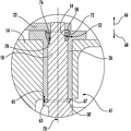
도 3a 및 도 3b는 밀봉 시스템의 제1 구현예의 단면도이다.
도 4a는 견고하지 않은 연결이 인서트와 샤프트 사이에 제공된 경우, 밀봉 시스템의 제2 구현예의 단면도이다.
도 4b는 견고한 연결이 인서트와 샤프트 사이에 제공된 경우, 밀봉 시스템의 제2 구현예의 단면도이다.
도 5는 밀봉 시스템의 제2 구현예의 대안적인 구성의 단면도이다.
도 6은 밀봉 시스템의 제3 구현예의 단면도이다.
도 7은 밀봉 시스템의 밀봉면들이 절두-원추형인 대안적인 장치의 단면도이다.
도 8은 밀봉 시스템이 피스톤 링을 포함하는 대안적인 장치의 단면도이다.The invention is illustrated by way of example and not by way of limitation in the figures of like figures in which like reference numerals indicate similar components:
1 is a cross-sectional view of a conventional wastegate turbocharger.
2 is a cross-sectional view of the interface between the bushing and the shaft in a typical turbocharger, showing a gas leak path.
3A and 3B are cross-sectional views of a first embodiment of a sealing system.
4A is a cross-sectional view of a second embodiment of a sealing system when a non-solid connection is provided between the insert and the shaft.
4B is a cross-sectional view of a second embodiment of a sealing system when a rigid connection is provided between the insert and the shaft.
5 is a cross-sectional view of an alternative configuration of a second embodiment of the sealing system.
6 is a cross-sectional view of a third embodiment of a sealing system.
7 is a cross-sectional view of an alternative device in which the sealing faces of the sealing system are truncated-conical.
8 is a cross-sectional view of an alternative arrangement in which the sealing system comprises a piston ring.
본원에 설명된 배치들은 샤프트와 주변 구조 사이(예컨대, 피벗 샤프트와 피벗 샤프트 부싱 사이)의 경계면을 위한 개선된 밀봉 시스템을 구비한 장치 터보차저와 관련된다. 상세한 구현예들이 본원에 개시된다; 그러나, 개시된 구현예들은 단지 예시의 목적이라는 것을 이해해야 한다. 따라서, 본원에 개시된 특정한 구조적, 기능적 상세는 제한의 의도로 해석되는 것이 아니라, 당업자가 실제로 임의의 적절하게 상세화된 구조에서 본원의 양상들을 다양하게 채용하도록 교시하기 위한 대표적인 근거 및 청구범위를 위한 근거로만 해석되어야 한다. 게다가, 본원에 사용된 용어들 및 문구들은 제한의 의도가 아니라, 가능한 실시예들의 이해할 만한 설명을 제공하도록 의도된 것이다. 배치들이 도 3 내지 도 8에 도시되었지만, 구현예들은 도시된 구조 또는 응용에 제한되지 않는다.The arrangements described herein relate to an apparatus turbocharger with an improved sealing system for the interface between the shaft and the surrounding structure (eg, between the pivot shaft and the pivot shaft bushing). Detailed embodiments are disclosed herein; However, it should be understood that the disclosed embodiments are merely for purposes of illustration. Accordingly, the specific structural and functional details disclosed herein are not to be construed as limiting, but rather to the representative basis and claims for teaching those skilled in the art to variously employ aspects of the disclosure in any suitably detailed structure. Should only be interpreted as. In addition, the terms and phrases used herein are not intended to be limiting, but rather to provide an understandable description of possible embodiments. Although arrangements are shown in FIGS. 3-8, implementations are not limited to the illustrated structure or application.
구현예들은 회전 가능한 또는 이동 가능한 부재(예컨대, 샤프트, 피벗 샤프트, 또는 피벗 샤프트에 구비된 부재) 및 주변 구조(예컨대, 피벗 샤프트 부싱) 상에 구비된 상보적인 감소형 밀봉면들의 사용, 및 터보차저의 작동 중에 이러한 밀봉면들의 결합을 유지하기 위한 시스템에 관한 것이다.Embodiments include the use of complementary reduced sealing surfaces provided on a rotatable or movable member (eg, a member on a shaft, pivot shaft, or pivot shaft) and a peripheral structure (eg, pivot shaft bushing), and turbo A system for maintaining the engagement of these sealing surfaces during operation of the charger.
감소형 밀봉면들은 임의의 적절한 형태를 가질 수 있다. 일반적으로, 감소형 밀봉면들의 직경 또는 폭은 샤프트 또는 회전 가능한 부재의 길이를 따라 감소할 수 있다. 일 구현예에서, 하나의 밀봉면은 감소형 오목 영역을 포함할 수 있고, 다른 밀봉면은 상보적인 감소형 볼록 영역을 포함할 수 있다.The reduced sealing surfaces can have any suitable shape. In general, the diameter or width of the reduced sealing surfaces may decrease along the length of the shaft or rotatable member. In one embodiment, one sealing surface may comprise a reduced concave region and the other sealing surface may comprise a complementary reduced convex region.
적절한 감소형 밀봉면들의 예로, 대략 절두-원추형, 절두-구형, 부분 원추형, 부분 구형, 단차형, 평면형 및 원추형 또는 평면형 및 구형의 조합, 또는 상이한 각도의 원추면들의 조합, 또는 상이한 곡률면들의 조합으로 이루어진 면들이 포함될 수 있고, 이들은 샤프트와 부싱의 경계면에서 사용된다. 원추면들은 임의의 적절한 각도로 구비될 수 있고, 곡률면들은 임의의 적절한 곡률로 구비될 수 있다. 감소형 밀봉면들은 샤프트 축과 실질적으로 동축을 가질 수 있다. 이러한 감소형 밀봉면들 및 다른 감소형 밀봉면들이 WO 2011/149867 A2에 기재되어 있고, 그 개시가 본원에 참조로 포함된다.Examples of suitable reduced sealing surfaces are, for example, approximately truncated-conical, truncated-spherical, partially conical, partially spherical, stepped, planar and conical or a combination of planar and spherical, or a combination of conical surfaces of different angles, or a combination of different curvature surfaces. Surfaces may be included, which are used at the interface between the shaft and the bushing. Conical surfaces may be provided at any suitable angle and curvature surfaces may be provided at any suitable curvature. The reduced sealing surfaces can be substantially coaxial with the shaft axis. Such reduced sealing surfaces and other reducing sealing surfaces are described in WO 2011/149867 A2, the disclosure of which is incorporated herein by reference.
후술하는 내용은 회전 부재(예컨대, 웨이스트게이트 피벗 샤프트 또는 VTG 제어 샤프트)와 주변 구조(예컨대, 부싱 또는 터빈 하우징) 사이의 경계면과 관련하여 설명될 것이다. 그러나, 본원에 설명된 구현예들이, 회전 부재가 다른 구조 내에 적어도 부분적으로 수용되는, 터보차저의 임의의 적절한 위치에서 사용될 수 있음은 물론이다.The following will be described in relation to the interface between the rotating member (eg, wastegate pivot shaft or VTG control shaft) and the surrounding structure (eg, bushing or turbine housing). However, it is to be understood that the embodiments described herein can be used in any suitable position of the turbocharger, in which the rotating member is at least partially received in another structure.
샤프트 밀봉 시스템(50)의 제1 구현예의 일례가 도 3a 및 도 3b에 도시되어 있다. 밀봉 시스템(50)은 상술한 회전 가능한 부재로서 피벗 샤프트(18)와 피벗 샤프트(18)에 연결된 웨이스트 게이트 밸브(16)를 포함하고, 샤프트(18) 주변에 보어를 가진 구조로서 부싱(26)을 포함한다. 시스템(50)은 피벗 샤프트(18)와 부싱(26) 사이에 구비되는 한 쌍의 상보적인 감소형 밀봉면들(52, 54)을 포함할 수 있다. 밀봉면들(52, 54)은 절두-원추형으로 도시되어 있지만, 밀봉면들(52, 54)이 임의의 적절한 구성을 가질 수 있음은 물론이다(몇가지 예가 상기에 설명되었다). 밀봉면들(52, 54)은 형상의 정점이 피벗 샤프트(18)에 의해 점유된 영역 내에 있어 "절단(cut off)"될 것이기 때문에 "절두"-원추형 또는 "절두"-구형으로 지칭된다. 이러한 절두-원추형 경계면은 피벗 샤프트(18)가 부싱(26) 내에 센터링되는 동안 부싱(26) 위에서 흔들리거나 기울어지는 것을 방지할 수 있다.One example of a first embodiment of the
부싱(26)은 플랜지(56)에 의해 축방향으로 구속될 수 있다. 부싱(26)은 피벗 샤프트 부싱(26)의 외경과 터빈 하우징(14) 사이에 삽입된 핀(미도시)에 의해 축방향으로 및 각지게 구속될 수 있거나, 또는 부싱(26)의 안쪽 단부를 향한 기계적 결합 및/또는 다른 적절한 수단에 의해 축방향으로 구속될 수 있다.
일 구현예에서, 도 3a 및 도 3b에 도시된 바와 같이, 밀봉면(54)은 샤프트(18) 자체에 의해 한정될 수 있다. 이 경우, 특징부가 예컨대 기계가공에 의해 샤프트(18)에 형성될 수 있다. 대안적으로, 밀봉면(18)은 예컨대 압입, 기계적 결합, 체결구, 접착제, 및/또는 다른 적절한 부착 수단에 의해 샤프트(18)에 견고하게 부착될 수 있는 별개의 부재(미도시)에 의해 한정될 수 있다. 도 3은 샤프트 상의 밀봉면(54)을 볼록한 절두-원추형으로, 부싱(26)에 구비된 밀봉면(52)을 오목한 절두-원추형으로 도시하고 있지만, 정반대의 배치가 제공될 수 있음은 물론이다. 즉, 볼록한 절두-원추형 밀봉면이 부싱(26)에 구비될 수 있고, 오목한 절두-원추형 밀봉면이 샤프트(18)에 구비될 수 있다.In one embodiment, as shown in FIGS. 3A and 3B, the sealing
시스템(50)은 편향 부재를 더 포함할 수 있다. 일례로, 편향 부재는 스프링(58)일 수 있다. 스프링(58)은 나선형 스프링 또는 파형 스프링과 같은 임의의 적절한 유형의 스프링일 수 있다. 도 3a 및 도 3b에 도시된 배치에서, 스프링(58)은 샤프트(18)의 일부를 둘러싼 구조와 샤프트(18)의 바깥쪽 단부 영역(60)에 부착된 구조 사이에 작동 가능하게 위치할 수 있다. 예컨대, 스프링(58)은 피벗 샤프트 부싱(26)과 샤프트(18)의 단부 영역(60)에 부착된 레버 암(22) 사이에 작동 가능하게 위치할 수 있다. 레버 암(22)은 하나 이상의 체결구, 기계적 결합, 접착제, 용접, 및/또는 다른 수단과 같은 임의의 적절한 방식으로 샤프트(18)에 작동 가능하게 연결될 수 있다. 본원에 사용된 바와 같이, "작동 가능하게 연결된(operatively connected)"이라는 표현은 직접적인 물리적 접촉이 없는 연결을 포함한 직접 또는 간접 연결을 포함할 수 있다. "바깥쪽" 및 "안쪽"이라는 표현은, 웨이스트게이트 밸브(16), 또는 샤프트(18)의 이동이 직접적으로 또는 간접적으로 영향을 미치는 다른 부재에 대한, 샤프트(18)의 일부의 일반적인 위치를 나타내기 위해 편의상 피벗 샤프트(18)와 관련하여 사용된다. 따라서, 샤프트(18)의 "안쪽" 부분은 샤프트(18)의 "바깥쪽" 부분보다 웨이스트게이트 밸브(16)에 더 근접하게 위치한다. 이에 따르면, 레버 암(22)은 샤프트(18)의 바깥쪽 부분인 단부 영역(60)에 작동 가능하게 연결된 구조라고 할 수 있다.
스프링(58)은 피벗 샤프트 부싱(26)의 외부-대향면(62) 및 레버 암(22)의 부싱-대향면(64)을 작동 가능하게 결합시킬 수 있다. 그러므로, 스프링(58)은 피벗 샤프트 부싱(26)의 외부-대향면(62) 상에 대략 제2 방향(68)으로 힘을 가할 수 있다. 스프링(58)은 동시에 레버 암(22)의 부싱-대향면(64) 상에 제1 방향(66)으로 힘을 가할 수 있다. 제1 방향(66)은 제2 방향(68)과 정반대일 수 있다. 그 결과, 밀봉면(52)은 스프링(58)의 힘으로 인해 제2 방향(68)으로(즉, 도 3b에 도시된 배치의 아래쪽으로) 밀릴 수 있다. 레버 암(22)이 스프링(58)에 의해 제1 방향(66)으로 밀리고, 그로 인해 작동 가능하게 연결된 피벗 샤프트(18)가 그와 함께 당겨짐에 따라, 밀봉면(54)은 제1 방향(66)으로(즉, 도 3b에 도시된 배치의 위쪽으로) 당겨질 수 있다. 따라서, 한 쌍의 상보적인 밀봉면들(52, 54)은 스프링(58)의 반동에 의해 서로 결합되어, 가스 및 매연의 유동이 터빈 하우징(14)으로부터 주변 환경으로 빠져나가는 것을 방지하기 위해 밀봉을 형성할 수 있다. 이러한 밀봉은 스프링(58)에 의해 가해진 지속적인 힘에 의해 유지될 수 있다.The
한 쌍의 밀봉면들(52, 54)을 이용한 스프링(58)의 셀프-센터링 작용은 피벗 샤프트(18)를 축(70)을 중심으로 원하는 회전축과 실질적으로 동심을 갖도록 당기므로, 액추에이터의 시트 압력 요건에 의해 야기된 코크 작용(cocking action)에 저항할 수 있다. 그 결과, 웨이스트게이트 밸브면과 이 면이 밀봉하는 웨이스트게이트 포트의 중첩이 더 작아질 수 있으므로, 웨이스트게이트 밸브 헤드의 크기를 감소시킬 가능성을 가져올 수 있다.The self-centering action of the
샤프트 밀봉 시스템(50')의 제2 구현예가 도 4a 및 도 4b에 도시되어 있다. 본 구현예에서, 한 쌍의 상보적인 감소형 밀봉면들(52, 54)이 "바깥쪽 밀봉"을 형성하기 위해 웨이스트게이트 피벗 샤프트(18)의 외부를 향해 위치할 수 있다. 밀봉면들(52, 54)의 상기 설명이 시스템(50')에 동일하게 적용될 수 있다. 샤프트(18) 상의 밀봉면(54)은 볼록한 절두-원추형일 수 있고, 부싱(26)에 구비된 밀봉면(52)은 오목한 절두-원추형일 수 있다. 밀봉면(54)은 샤프트(18)에 의해 한정될 수 있다. 그러나, 몇몇 경우에, 이러한 배치는 가능하지 않거나 실용적이지 않을 수 있다. 예컨대, 레버 암(22)이 통상적으로 터빈 하우징(14)의 내부로부터 터빈 하우징의 외부를 향한(도 4a의 도면의 상부를 향한) 방향으로 조립되기 때문에, 밀봉면(54)은 웨이스트게이트 피벗 샤프트(18)가 부싱(26)에 삽입된 후(피벗 샤프트가 부싱 내에 존재하게 된다) 피벗 샤프트(18)에 조립되는 별개의 인서트(72)에 구비될 수 있다.A second embodiment of the shaft sealing system 50 'is shown in FIGS. 4A and 4B. In this embodiment, a pair of complementary reduced sealing surfaces 52, 54 may be located towards the outside of the
인서트(72)는, 샤프트(18)가 예컨대 축(70)의 방향을 따라 인서트(72)에 대해 이동할 수 있도록, 예컨대 견고하지 않은 방식을 포함한 임의의 적절한 방식으로 샤프트(18)에 부착될 수 있다. 그러나, 다른 경우에, 인서트(72)는 샤프트(18)에 견고하게 부착될 수 있다. "견고하게 부착된(rigidly attached)"이라는 표현은 인서트(72)가 샤프트(18)와 함께 형성되거나, 또는 샤프트(18) 및 인서트(72)가 적어도 축(70)의 방향으로 서로에 대해 실질적으로 이동하지 않도록(즉, 적어도 축(70)의 방향으로 함께 이동하도록), 인서트(72)가 샤프트(18)에 부착되는 것을 의미한다. 견고한 부착의 예로, 예컨대, 압입, 기계적 결합, 체결구, 접착제, 및/또는 다른 적절한 부착 수단이 포함될 수 있다.
인서트(72)는 임의의 적절한 재료로 이루어질 수 있다. 예컨대, 인서트(72)는 적어도 마찰 및/또는 갈바닉 부식의 관점에서 샤프트(18) 및/또는 부싱(26)과 양립 가능한 내고온성 금속으로 이루어질 수 있다.
시스템(50')은 편향 부재를 더 포함할 수 있다. 일례로, 편향 부재는 스프링(58)일 수 있다. 스프링(58)은 나선형 스프링 또는 파형 스프링과 같은 임의의 적절한 유형의 스프링일 수 있다. 도 4a에 도시된 배치에서, 스프링(58)은 인서트(72)(또는 밀봉면(54)이 샤프트(18)에 구비된 경우 심지어 샤프트(18) 자체) 및 레버 암(22)과 같이 샤프트(18)의 바깥쪽 단부 영역(60)에 부착된 구조 사이에 작동 가능하게 위치할 수 있다. 이러한 배치는 인서트(72)가 예컨대 슬립 핏(slip fit)에 의해 샤프트(18)에 견고하지 않게 부착되는 경우에 적절할 수 있다. 견고하지 않은 배치에서, 샤프트(18) 및 인서트(72)는 적어도 축(70)의 방향으로 서로에 대해 이동할 수 있다.System 50 'may further include a biasing member. In one example, the biasing member may be a
스프링(58)은 레버 암(22)의 부싱-대향면(64)뿐만 아니라 샤프트(18) 또는 인서트(72)의 외부-대향면(74)을 작동 가능하게 결합시킬 수 있다. 그러므로, 스프링(58)은 레버 암(22)의 부싱-대향면(64) 상에 제1 방향(66)으로 힘을 가할 수 있다. 스프링(58)은 동시에 인서트(72)의 외부-대향면(74) 상에 대략 제2 방향(68)으로 힘을 가할 수 있다. 그 결과, 밀봉면(54)은 스프링(58)의 힘으로 인해 제2 방향(68)으로(즉, 도 4a에 도시된 배치의 아래쪽으로) 밀릴 수 있다. 레버 암(22)이 스프링(58)에 의해 제1 방향(66)으로 밀리고, 그로 인해 작동 가능하게 연결된 피벗 샤프트(18)가 그와 함께 당겨짐에 따라, 부싱(26)에 구비된 밀봉면(52)은 제1 방향(66)으로(즉, 도 4a에 도시된 배치의 위쪽으로) 당겨질 수 있다. 이후, 피벗 샤프트(18)는 부싱(26)(예컨대, 단부면(65))과 샤프트(18)(예컨대, 견부면(63)) 사이의 결합으로 인해 부싱(26)을 당길 수 있다. 따라서, 한 쌍의 상보적인 밀봉면들(52, 54)은 스프링(58)의 반동에 의해 서로 결합되어, 가스 및 매연의 유동이 터빈 하우징(14)으로부터 주변 환경으로 빠져나가는 것을 방지하기 위해 밀봉을 형성할 수 있다. 이러한 밀봉은 스프링(58)에 의해 가해진 지속적인 힘에 의해 유지될 수 있다.The
전술한 바와 같이, 인서트(72)가 샤프트(18)와 함께 형성되거나 견고한 방식으로 샤프트(18)에 부착되는 구현예들에서, 스프링(58) 또는 다른 편향 부재가 샤프트(18)(또는 샤프트(18)에 연결된 다른 구조)와 부싱(26)의 단부면(65) 사이의 경계면에 작동 가능하게 위치할 수 있다. 이러한 배치의 일례가 도 4b에 도시되어 있다.As described above, in embodiments in which the
이 경우, 스프링(58)은 부싱(26)의 단부(65) 상에 대략 제1 방향(66)으로 힘을 가하여, 밀봉면(52)을 제1 방향(66)으로 밀 수 있다. 스프링(58)은 동시에 샤프트(18)(또는 샤프트(18)에 연결된 다른 구조) 상에 제2 방향(68)으로 힘을 가할 수 있다. 일례로, 스프링(58)은 샤프트(18)의 견부면(63)에 힘을 가할 수 있다. 견부면(63)은 스프링(58)을 수용하기 위한 요홈(67)을 포함할 수 있다. 그 결과, 밀봉면(54)은 샤프트(18)가 인서트(72)에 견고하게 부착될 때의 스프링(58)의 힘으로 인해 제2 방향(68)으로(즉, 도 4b에 도시된 배치의 아래쪽으로) 당겨질 수 있다. 따라서, 한 쌍의 상보적인 밀봉면들(52, 54) 사이에 밀봉이 형성되고 유지될 수 있다.In this case, the
밀봉 시스템의 다른 예가 도 5에 도시되어 있다. 이러한 배치에서, 절두-구면(52)과 인서트(72)의 내경의 교차점은 편평면(76)을 형성하기 위해 짧게 절단될 수 있다. 편평면(76)은 회전축(70)을 대략 횡단할 수 있다. 일 구현예에서, 편평면(76)은 축(70)에 실질적으로 수직일 수 있다. 도 5에 도시된 바와 같이, 예컨대 샤프트(18)의 외경을 감소시킴으로써, 샤프트(18)에 접경 랜딩부(78)를 형성할 수 있다. 이러한 배치에서, 제1 스프링(58)이 인서트(72)(또는 밀봉면(54)이 샤프트(18)에 구비된 경우 심지어 샤프트(18) 자체)와 샤프트(18)에 부착된 구조(레버 암(22)) 사이에 작동 가능하게 위치할 수 있다. 또한, 제2 스프링(58') 또는 다른 편향 부재가 샤프트(18)(또는 샤프트(18)에 연결된 다른 구조)와 부싱(26)의 단부면(65) 사이에 작동 가능하게 위치할 수 있다. 예컨대, 제2 스프링(58')은 샤프트(18)의 견부면(63)을 작동 가능하게 결합시킬 수 있다. 다시, 견부면(63)은 요홈(67)을 포함할 수 있다.Another example of a sealing system is shown in FIG. 5. In this arrangement, the intersection of the truncated-
제1 스프링(58)은 레버 암(22)과 인서트(72)를 작동 가능하게 결합시킬 수 있다. 그러므로, 제1 스프링(58)은 레버 암(22) 상에서 대략 제1 방향(66)으로 힘을 가할 수 있다. 제1 스프링(58)은 또한 인서트(72) 상에서 대략 제2 방향(68)으로 힘을 가할 수 있다. 따라서, 밀봉면(54) 및 편평면(76)은 스프링(58)의 힘으로 인해 제2 방향(68)으로(즉, 도 5에 도시된 배치의 아래쪽으로) 밀릴 수 있다.The
제2 스프링(58') 또는 다른 편향 부재는 샤프트(18)의 견부면(63)(또는 샤프트(18)에 연결된 다른 구조)과 부싱(26)의 단부면(65) 사이에 작동 가능하게 위치할 수 있다. 이 경우, 제2 스프링(58')은 부싱(26)의 단부(65) 상에 대략 제1 방향(66)으로 힘을 가하여, 밀봉면(52)을 제1 방향(66)으로(즉, 도 5에 도시된 배치의 위쪽으로) 밀 수 있다.The
제1 스프링(58)에 의해 가해진 힘은 인서트(72)의 내부 대향 편평면(76) 및 샤프트(18)의 접경 랜딩부(78)를 서로를 향해 및 서로 접촉하도록 밀 수 있다. 편평면(76)과 접경 랜딩부(78) 사이의 이러한 접촉은 실질적인 밀봉 결합을 초래하여, 샤프트(18)와 인서트(72) 사이의 추가적인 밀봉 경계면을 형성하여, 매연 및 가스 누출을 최소화할 수 있다. 밀봉 경계면은 제1 스프링(58)에 의해 가해진 힘에 의해 유지될 수 있다.The force exerted by the
게다가, 제1 스프링(58)에 의해 가해진 힘은 밀봉면(54)을 제2 방향(68)으로 밀고, 제2 스프링(58')에 의해 가해진 힘은 밀봉면(52)을 제1 방향(66)으로 밀 수 있다. 그 결과, 밀봉면들(52, 54)은 서로 실질적으로 밀봉 접촉할 수 있다. 밀봉면들(52, 54) 사이의 실질적인 밀봉 접촉은 제1 및 제2 스프링(58, 58')에 의해 유지될 수 있다.In addition, the force exerted by the
몇몇 경우에, 인서트(72)는, 편평면(76) 및 접경 랜딩부(78)가 서로 직접적으로 접경하도록, 제자리에 클램핑될 수 있다는 것을 주목해야 한다. 이러한 배치는 레버 암(22)을 샤프트(18)에 용접함으로써 유지될 수 있다. 이 경우, 밀봉면들(52, 54)은 서로 접촉할 수 있으며, 제2 스프링(58')에 의해 접촉 유지될 수 있기 때문에, 제1 스프링(58)이 필요하지 않을 수 있다.In some cases, it should be noted that the
샤프트 밀봉 시스템(50")의 제3 구현예가 도 6에 도시되어 있다. 본 구현예에서, 상보적인 절두-구면들의 쌍들이 "안쪽 밀봉" 및 "바깥쪽 밀봉"을 형성하기 위해 두 위치에 구비된다. 일례로, 도 6은 도 3a, 도 3b, 및 도 4에 구비된 양상들의 하나의 가능한 조합을 도시한다. 스프링(58)은 레버 암(22)뿐만 아니라 인서트(72) 또는 샤프트(18)를 작동 가능하게 결합시킬 수 있다. 그러므로, 스프링(58)은 레버 암(22) 상에 제1 방향(66)으로 힘을 가할 수 있다. 스프링(58)은 동시에 인서트(72) 상에 대략 제2 방향(68)으로 힘을 가할 수 있다. 그 결과, 바깥쪽 밀봉면(54)은 스프링(58)의 힘으로 인해 제2 방향(68)으로(즉, 도 6에 도시된 배치의 아래쪽으로) 밀릴 수 있다. 레버 암(22)이 스프링(58)에 의해 제1 방향(66)으로 밀리고, 그로 인해 작동 가능하게 연결된 피벗 샤프트(18) 및 부싱(26)이 그와 함께 당겨짐에 따라, 바깥쪽 밀봉면(52)은 제1 방향(66)으로(즉, 도 6에 도시된 배치의 위쪽으로) 당겨질 수 있다. 따라서, 한 쌍의 상보적인 밀봉면들(52, 54)은 스프링(58)의 반동에 의해 서로 결합되어, 가스 및 매연의 유동이 터빈 하우징(14)으로부터 주변 환경으로 빠져나가는 것을 방지하기 위해 밀봉을 형성할 수 있다. 이러한 밀봉은 스프링(58)에 의해 가해진 지속적인 힘에 의해 유지될 수 있다.A third embodiment of the
본 배치에서, 스프링(58)에 의해 가해진 힘은 안쪽의 볼록한 절두-구면(54')을 안쪽의 오목한 절두-구면(52') 내로 당길 수 있다. 스프링(58)에 의해 가해진 힘은 또한 인서트(72)를 안쪽으로(즉, 도 6의 아래쪽으로) 밀어서, 바깥쪽의 볼록한 절두-구면(54')을 바깥쪽의 오목한 절두-구면(54') 내로 가압하고, 그로 인해 트윈 센터링 메커니즘 및 트윈 밀봉 경계면을 제공할 수 있다. 도 6에 도시된 배치는 인서트(72)가 샤프트(18)에 견고하지 않게 부착되는(예컨대, 슬립핏되는) 구현예들에 적합하다.In this arrangement, the force exerted by the
전술한 바와 같이, 상보적인 감소형 밀봉면들(52, 54)은 임의의 적절한 구성을 가질 수 있다. 그러므로, 밀봉면들이 도 3 내지 도 6에 절두-구면들로 도시되어 있지만, 구현예들은 절두-구면 밀봉면들에 제한되지 않음은 물론이다. 실제로, 도 7은 밀봉면들이 절두-원추면들로 구성되는 대안적인 배치를 도시한다. 본 구성에서, 절두-원추형 밀봉면(54)을 포함하는 인서트(72)가 부싱(26)의 상보적인 절두-원추형 밀봉면(52) 내로 밀려서, 부싱(26) 내에 인서트(72) 및 샤프트(18)를 센터링하고, 매연 및 가스가 터빈 하우징 내부로부터 주변 환경으로 이동하는 것을 방지하기 위해 밀봉 경계면을 제공한다.As mentioned above, the complementary reduced sealing surfaces 52, 54 may have any suitable configuration. Therefore, although the sealing surfaces are shown as truncated-spherical surfaces in FIGS. 3-6, embodiments are of course not limited to truncated-spherical sealing surfaces. In practice, FIG. 7 shows an alternative arrangement in which the sealing surfaces consist of truncated-conical surfaces. In this configuration, the
도 8은 밀봉 시스템의 또 다른 대안적인 장치를 제시한다. 인서트의 보어의 내경과 피벗 샤프트(18)의 외주면(30) 사이의 누출 경로를 밀봉하기 위해, 피스톤 링(80)과 같은 하나 이상의 링 밀봉을 사용할 수 있다.8 presents another alternative arrangement of a sealing system. One or more ring seals, such as piston rings 80, may be used to seal the leak path between the bore of the insert and the outer
전술한 배치들이 효과적인 밀봉 시스템을 제공할 수 있음은 물론이다. 스프링을 구비함으로써, 실질적으로 모든 터보차저 작동 조건들에서 밀봉을 유지할 수 있다. 따라서, 밀봉 시스템은 밀봉면들을 함께 유지하기 위해 작동 조건들(예컨대, 터빈 하우징 압력)에 좌우되지 않는다. 게다가, 본원에 제시된 밀봉 시스템은 종전에 사용된 피스톤 링 밀봉 시스템보다 작동 가능한 구성요소들의 오정렬을 훨씬 더 견딜 수 있다. 본원에 사용된 "부정관사(a, an)"는 1개, 또는 2개 이상으로 정의된다. 본원에 사용된 "복수"라는 용어는 2개, 또는 3개 이상으로 정의된다. 본원에 사용된 "다른"이라는 용어는 적어도 제2, 또는 그 이상으로 정의된다. 본원에 사용된 "포함하는(including)" 및/또는 "구비한"이라는 용어는 포함하는(comprising)으로 정의된다(즉, 개방형 언어).It goes without saying that the above arrangements can provide an effective sealing system. By having a spring, it is possible to maintain a seal at virtually all turbocharger operating conditions. Thus, the sealing system is not dependent on operating conditions (eg turbine housing pressure) to keep the sealing surfaces together. In addition, the sealing system presented herein can withstand even more misalignment of the operable components than previously used piston ring sealing systems. As used herein, "a, an" is defined as one, or two or more. The term plurality, as used herein, is defined as two, three, or more than two. The term "other" as used herein is defined as at least a second, or more. As used herein, the terms "including" and / or "included" are defined as comprising (ie, open language).
본원에 설명된 양상들은 본 발명의 정신 또는 본질적인 속성을 벗어남 없이 다른 형태들 및 조합들로 구현될 수 있다. 따라서, 구현예들은 단지 예로써 주어진 본원에 설명된 특정한 상세에 제한되지 않으며, 후술하는 청구범위 내에서 다양한 수정들 및 변경들이 가능하다는 점을 물론 이해할 것이다.Aspects described herein may be embodied in other forms and combinations without departing from the spirit or essential attributes of the invention. Accordingly, it will of course be understood that the embodiments are not limited to the specific details described herein given by way of example only, and that various modifications and changes are possible within the scope of the following claims.
Claims (16)
하우징;
연관된 회전축(70), 안쪽 부분(61), 및 바깥쪽 부분(60)을 구비한 샤프트(18)를 포함하는 회전 가능한 부재;
상기 샤프트(18)의 상기 바깥쪽 부분(60)에 작동 가능하게 연결되는 제1 구조;
상기 회전 가능한 부재의 적어도 일부를 수용하는 보어를 가진 제2 구조;
제1 밀봉면(52) 및 제2 밀봉면(54)을 포함하는 한 쌍의 상보적인 감소형 밀봉면들(52, 54)로서, 상기 제2 밀봉면(54)은 상기 회전 가능한 부재의 상기 안쪽 부분(61)에 구비되며, 상기 제1 밀봉면(52)은 상기 보어를 가진 상기 제2 구조에 구비되고, 상기 보어를 가진 제2 구조는 반경 방향 외측으로 연장되는 플랜지를 더 포함하고, 상기 플랜지는 상기 보어를 가진 제2 구조를 상기 하우징에 대해 축방향으로 구속하도록 구성되고 배치되는, 상기 한 쌍의 상보적인 감소형 밀봉면들(52, 54); 및
상기 보어를 가진 제2 구조 및 상기 샤프트(18)의 상기 바깥쪽 부분(60)에 작동 가능하게 연결되는 제1 구조 사이에 작동 가능하게 위치하는 편향 부재(58)로서, 상기 회전 가능한 부재의 상기 안쪽 부분(61)에 제공되어 있는 상기 제1 밀봉면(52)을 상기 샤프트를 따라서 제1 방향(66)으로 당기기 위하여 상기 제1 방향(66)으로 상기 샤프트(18)의 상기 바깥쪽 부분(60)에 작동 가능하게 연결되는 제1 구조에 힘을 가하며, 상기 보어를 가진 제2 구조에 제공되어 있는 다른 하나의 밀봉면(52)을 상기 제1 방향(66)과 정반대인 제2 방향(68)으로 밀어내기 위하여 상기 제2 방향으로 상기 보어를 가진 제2 구조에 추가로 힘을 가하여, 밀봉을 형성하도록 상기 밀봉면들(52, 54)을 서로 결합시키는, 상기 편향 부재(58);를 포함하는 밀봉 시스템.In the sealing system 50 for a turbocharger,
housing;
A rotatable member comprising a shaft 18 having an associated axis of rotation 70, an inner portion 61, and an outer portion 60;
A first structure operatively connected to said outer portion (60) of said shaft (18);
A second structure having a bore for receiving at least a portion of the rotatable member;
A pair of complementary reduced sealing surfaces 52, 54 that include a first sealing surface 52 and a second sealing surface 54, wherein the second sealing surface 54 is the upper portion of the rotatable member. Is provided in the inner portion 61, the first sealing surface 52 is provided in the second structure with the bore, the second structure with the bore further comprises a flange extending radially outward, The flange is configured and arranged to axially constrain the second structure with the bore relative to the housing; And
A biasing member 58 operatively positioned between a second structure with the bore and a first structure operably connected to the outer portion 60 of the shaft 18, wherein the The outer portion of the shaft 18 in the first direction 66 for pulling the first sealing surface 52 provided in the inner portion 61 in the first direction 66 along the shaft. And a second sealing surface 52 provided in the second structure with the bore to apply a force to the first structure operably connected to the second structure. Said biasing member (58) for applying additional force to said second structure with said bore in said second direction to push it into said second to engage said sealing surfaces (52, 54) to form a seal; Sealing system comprising a.
상기 샤프트(18)는 VTG 또는 웨이스트게이트 피벗 샤프트(18)이며, 상기 샤프트(18)에 부착되는 상기 제1 구조는 레버 암(22)인, 밀봉 시스템.The method of claim 1,
The shaft (18) is a VTG or wastegate pivot shaft (18) and the first structure attached to the shaft (18) is a lever arm (22).
상기 보어를 가진 상기 제2 구조는 부싱(26)인, 밀봉 시스템.The method of claim 1,
The sealing system with the bore is a bushing (26).
상기 감소형 밀봉면들(52, 54)은 절두-원추형인, 밀봉 시스템.The method of claim 1,
The reduced sealing surfaces (52, 54) are truncated-conical.
상기 감소형 밀봉면들(52, 54)은 절두-구형인, 밀봉 시스템.The method of claim 1,
The reduced sealing surfaces (52, 54) are truncated-spherical.
상기 회전 가능한 부재는 상기 샤프트(18)에 작동 가능하게 연결되는 인서트(72)를 포함하고, 상기 회전 가능한 부재의 상기 안쪽 부분(61)에 구비된 상기 제2 밀봉면은 상기 인서트(72)에 의해 한정되는, 밀봉 시스템.The method of claim 1,
The rotatable member includes an insert 72 operably connected to the shaft 18, wherein the second sealing surface provided on the inner portion 61 of the rotatable member is connected to the insert 72. Defined by the sealing system.
상기 샤프트(18)의 상기 안쪽 부분(61)에 구비된 상기 제2 밀봉면은 상기 샤프트(18)에 의해 한정되는, 밀봉 시스템.The method of claim 1,
The second sealing surface provided on the inner part (61) of the shaft (18) is defined by the shaft (18).
하우징;
연관된 회전축(70), 안쪽 부분(61), 및 바깥쪽 부분(60)을 구비한 샤프트(18)를 포함하는 회전 가능한 부재;
상기 샤프트(18)의 상기 바깥쪽 부분(60)에 작동 가능하게 연결되는 제1 구조;
상기 회전 가능한 부재의 적어도 일부를 수용하는 보어를 가진 제2 구조;
제1 밀봉면(52) 및 제2 밀봉면(54)을 포함하는 한 쌍의 상보적인 감소형 밀봉면들(52, 54)로서, 상기 제2 밀봉면(54)은 상기 회전 가능한 부재의 상기 바깥쪽 부분(60)에 구비되며, 상기 제1 밀봉면(52)은 상기 보어를 가진 제2 구조에 구비되는, 상기 한 쌍의 상보적인 감소형 밀봉면들(52, 54); 및
상기 회전 가능한 부재 및 상기 샤프트(18)의 상기 바깥쪽 부분(60)에 작동 가능하게 연결되는 제1 구조 사이에 작동 가능하게 위치하는 편향 부재(58)로서, 상기 회전 가능한 부재의 상기 바깥쪽 부분(60)에 제공되어 있는 상기 밀봉면들 제2 밀봉면(54)을 상기 샤프트를 따라서 제1 방향(66)으로 당기기 위하여 상기 제1 방향(66)으로 상기 샤프트(18)의 상기 바깥쪽 부분(60)에 작동 가능하게 연결되는 제1 구조에 힘을 가하며, 상기 보어를 가진 제2 구조에 제공되어 있는 상기 제1 밀봉면(52)을 상기 제1 방향(66)과 정반대인 제2 방향(68)으로 밀어내기 위하여 상기 제2 방향으로 상기 회전 가능한 부재에 추가로 힘을 가하여, 밀봉을 형성하도록 상기 밀봉면들(52, 54)을 서로 결합시키는, 상기 편향 부재(58);를 포함하는 밀봉 시스템.In a sealing system 50 'for a turbocharger,
housing;
A rotatable member comprising a shaft 18 having an associated axis of rotation 70, an inner portion 61, and an outer portion 60;
A first structure operatively connected to said outer portion (60) of said shaft (18);
A second structure having a bore for receiving at least a portion of the rotatable member;
A pair of complementary reduced sealing surfaces 52, 54 that include a first sealing surface 52 and a second sealing surface 54, wherein the second sealing surface 54 is the upper portion of the rotatable member. A pair of complementary reduced sealing surfaces (52, 54) provided in an outer portion (60), said first sealing surface (52) being provided in said second structure with said bore; And
A biasing member 58 operatively positioned between the rotatable member and a first structure operatively connected to the outer portion 60 of the shaft 18, the outer portion of the rotatable member The outer side of the shaft 18 in the first direction 66 to pull the sealing surfaces second sealing surface 54 provided in the 60 in the first direction 66 along the shaft. A first direction exerting a force on a first structure operatively connected to 60, the second direction opposite to the first direction 66, the first sealing surface 52 provided on the second structure with the bore; The biasing member (58), which additionally forces the rotatable member in the second direction to push it to (68), thereby coupling the sealing surfaces (52, 54) to each other to form a seal. Sealing system.
상기 샤프트(18)는 VTG 또는 웨이스트게이트 피벗 샤프트(18)이며, 상기 샤프트(18)에 부착되는 상기 제1 구조는 레버 암(22)인, 밀봉 시스템.The method of claim 8,
The shaft (18) is a VTG or wastegate pivot shaft (18) and the first structure attached to the shaft (18) is a lever arm (22).
상기 보어를 가진 상기 제2 구조는 부싱(26) 또는 터빈 하우징(14) 중 하나인, 밀봉 시스템.The method of claim 8,
The sealing system with the bore is either a bushing (26) or a turbine housing (14).
상기 감소형 밀봉면들(52, 54)은 절두-원추형인, 밀봉 시스템.The method of claim 8,
The reduced sealing surfaces (52, 54) are truncated-conical.
상기 감소형 밀봉면들(52, 54)은 절두-구형인, 밀봉 시스템.The method of claim 8,
The reduced sealing surfaces (52, 54) are truncated-spherical.
상기 회전 가능한 부재는 상기 샤프트(18)에 작동 가능하게 연결되는 인서트(72)를 포함하고, 상기 회전 가능한 부재의 상기 바깥쪽 부분(60)에 구비된 상기 제1 밀봉면은 상기 인서트(72)에 의해 한정되는, 밀봉 시스템.The method of claim 8,
The rotatable member includes an insert 72 operably connected to the shaft 18, wherein the first sealing surface provided on the outer portion 60 of the rotatable member includes the insert 72. Defined by a sealing system.
상기 회전 가능한 부재의 상기 바깥쪽 부분(60)에 구비된 상기 밀봉면은 상기 샤프트(18)에 의해 한정되는, 밀봉 시스템.The method of claim 8,
The sealing surface provided on the outer portion (60) of the rotatable member is defined by the shaft (18).
하우징;
연관된 회전축(70), 안쪽 부분(61), 및 바깥쪽 부분(60)을 구비한 샤프트(18)를 포함하는 회전 가능한 부재;
상기 샤프트(18)의 상기 바깥쪽 부분(60)에 작동 가능하게 연결되는 제1 구조;
상기 회전 가능한 부재의 적어도 일부를 수용하는 보어를 가진 제2 구조로서, 반경 방향 외측으로 연장되는 플랜지를 더 포함하고, 상기 플랜지는 상기 보어를 가진 제2 구조를 상기 하우징에 대해 축방향으로 구속하도록 구성되고 배치되는, 상기 보어를 가진 제2 구조;
제1 밀봉면(52') 및 제2 밀봉면(54')을 포함하는 제1 쌍의 상보적인 감소형 밀봉면들(52', 54')로서, 상기 제2 밀봉면(54')은 상기 회전 가능한 부재의 상기 안쪽 부분(61)에 구비되며, 상기 제1 밀봉면(52')은 상기 보어를 가진 제2 구조에 구비되는, 상기 제1 쌍의 상보적인 감소형 밀봉면들(52', 54');
제3 밀봉면(52) 및 제4 밀봉면을 포함하는 제2 쌍의 상보적인 감소형 밀봉면들(52, 54)로서, 제3 밀봉면은 상기 회전 가능한 부재의 상기 바깥쪽 부분(60)에 구비되며, 제4 밀봉면은 상기 보어를 가진 제2 구조에 구비되는, 상기 제2 쌍의 상보적인 감소형 밀봉면들(52, 54); 및
상기 회전 가능한 부재 및 상기 샤프트(18)의 상기 바깥쪽 부분(60)에 작동 가능하게 연결되는 제1 구조 사이에 작동 가능하게 위치하는 편향 부재(58)로서, 제1 방향(66)으로 상기 샤프트(18)의 상기 바깥쪽 부분(60)에 작동 가능하게 연결되는 제1 구조에 힘을 가하며, 상기 제1 방향(66)과 정반대인 제2 방향(68)으로 상기 회전 가능한 부재에 추가로 힘을 가하여, 제1 밀봉을 형성하도록 상기 제1 쌍의 밀봉면들(52', 54')을 서로 결합시키며, 제2 밀봉을 형성하도록 상기 제2 쌍의 밀봉면들(52, 54)을 서로 결합시키는, 상기 편향 부재(58);를 포함하는 밀봉 시스템.In a sealing system 50 "for a turbocharger,
housing;
A rotatable member comprising a shaft 18 having an associated axis of rotation 70, an inner portion 61, and an outer portion 60;
A first structure operatively connected to said outer portion (60) of said shaft (18);
A second structure having a bore to receive at least a portion of the rotatable member, the second structure further comprising a flange extending radially outward, the flange to axially constrain the second structure with the bore relative to the housing; A second structure having said bore, constructed and arranged;
A first pair of complementary reduced sealing surfaces 52 ', 54' comprising a first sealing surface 52 'and a second sealing surface 54', wherein the second sealing surface 54 ' The first pair of complementary reduced sealing surfaces 52 provided in the inner portion 61 of the rotatable member, the first sealing surface 52 ′ being provided in a second structure with the bore. ', 54');
A second pair of complementary reduced sealing surfaces 52, 54 that include a third sealing surface 52 and a fourth sealing surface, the third sealing surface being the outer portion 60 of the rotatable member. The second pair of complementary reduced sealing surfaces (52, 54) provided in the second structure with the bore; And
A biasing member 58 operatively located between the rotatable member and a first structure operatively connected to the outer portion 60 of the shaft 18, the shaft in a first direction 66. Exerts a force on a first structure operatively connected to the outer portion 60 of 18, and further forces on the rotatable member in a second direction 68 opposite to the first direction 66. Is applied to couple the first pair of sealing surfaces 52 ', 54' to each other to form a first seal, and the second pair of sealing surfaces 52, 54 to each other to form a second seal. And, the biasing member (58).
Applications Claiming Priority (3)
| Application Number | Priority Date | Filing Date | Title |
|---|---|---|---|
| US201261648163P | 2012-05-17 | 2012-05-17 | |
| US61/648,163 | 2012-05-17 | ||
| PCT/US2013/038970 WO2013173055A1 (en) | 2012-05-17 | 2013-05-01 | Shaft sealing system for a turbocharger |
Publications (2)
| Publication Number | Publication Date |
|---|---|
| KR20150013684A KR20150013684A (en) | 2015-02-05 |
| KR102075603B1 true KR102075603B1 (en) | 2020-03-02 |
Family
ID=49584159
Family Applications (1)
| Application Number | Title | Priority Date | Filing Date |
|---|---|---|---|
| KR1020147033963A KR102075603B1 (en) | 2012-05-17 | 2013-05-01 | Shaft sealing system for a turbocharger |
Country Status (7)
| Country | Link |
|---|---|
| US (1) | US20150097345A1 (en) |
| KR (1) | KR102075603B1 (en) |
| CN (1) | CN104271919B (en) |
| DE (1) | DE112013002028T5 (en) |
| IN (1) | IN2014DN09988A (en) |
| RU (1) | RU2014148497A (en) |
| WO (1) | WO2013173055A1 (en) |
Families Citing this family (19)
| Publication number | Priority date | Publication date | Assignee | Title |
|---|---|---|---|---|
| DE102012204497A1 (en) * | 2012-03-21 | 2013-09-26 | Mahle International Gmbh | Wastegate valve device |
| US9889323B2 (en) * | 2013-03-13 | 2018-02-13 | The Boeing Company | Fire seal end cap and associated multi-member assembly and method |
| DE102014207671B4 (en) * | 2014-04-24 | 2023-09-28 | Bayerische Motoren Werke Aktiengesellschaft | Exhaust gas turbocharger with a wastegate valve |
| WO2015190356A1 (en) | 2014-06-09 | 2015-12-17 | 株式会社Ihi | Supercharger |
| DE112015003981T5 (en) * | 2014-08-29 | 2017-05-11 | Ihi Corporation | turbocharger |
| CN106605052B (en) * | 2014-08-29 | 2019-03-15 | 株式会社Ihi | Flow variable valve mechanism and booster |
| JP6705146B2 (en) | 2015-10-07 | 2020-06-03 | 株式会社Ihi | Variable flow valve mechanism and supercharger |
| US10227916B2 (en) * | 2016-07-24 | 2019-03-12 | Garrett Transportation I Inc. | Turbocharger turbine wastegate assembly |
| US10233827B2 (en) * | 2016-07-24 | 2019-03-19 | Garrett Transportation I Inc. | Turbine wastegate |
| US10215088B2 (en) * | 2016-07-24 | 2019-02-26 | Garrett Transporation I Inc. | Method of assembling a turbine wastegate assembly |
| CN109563768B (en) * | 2017-03-30 | 2021-12-14 | 三菱重工发动机和增压器株式会社 | Exhaust bypass device and supercharger |
| US10590789B2 (en) * | 2017-04-26 | 2020-03-17 | Borgwarner Inc. | Turbocharger radial seal |
| JP6669707B2 (en) * | 2017-11-08 | 2020-03-18 | 本田技研工業株式会社 | Waste gate sealing jig |
| DE102017128830A1 (en) | 2017-12-05 | 2019-06-06 | Continental Automotive Gmbh | Wastegate arrangement for an exhaust gas turbocharger |
| EP3730759B1 (en) * | 2018-01-30 | 2022-08-31 | Mitsubishi Heavy Industries Engine & Turbocharger, Ltd. | Drive device, valve device equipped with drive device, and turbocharger link drive mechanism |
| US11242890B2 (en) * | 2018-07-03 | 2022-02-08 | GM Global Technology Operations LLC | Articulating joint with a high wear life |
| CN112424457B (en) | 2018-10-05 | 2022-06-28 | 株式会社Ihi | Bearing structure |
| DE102018217602A1 (en) * | 2018-10-15 | 2020-04-16 | Continental Automotive Gmbh | Exhaust gas turbine of an exhaust gas turbocharger with a sealed wastegate valve device and exhaust gas turbocharger |
| US10711690B2 (en) | 2018-11-06 | 2020-07-14 | Borgwarner Inc. | Wastegate assembly and turbocharger including the same |
Citations (2)
| Publication number | Priority date | Publication date | Assignee | Title |
|---|---|---|---|---|
| US20060213195A1 (en) * | 2003-07-11 | 2006-09-28 | Leavesley Malcolm G | Turbocharger apparatus having an exhaust gas sealing system for preventing gas leakage from the turbocharger apparatus |
| WO2011149867A2 (en) * | 2010-05-27 | 2011-12-01 | Borgwarner Inc. | Control shaft seal |
Family Cites Families (4)
| Publication number | Priority date | Publication date | Assignee | Title |
|---|---|---|---|---|
| US4363600A (en) * | 1981-04-06 | 1982-12-14 | General Motors Corporation | Variable vane mounting |
| JP2005113797A (en) * | 2003-10-08 | 2005-04-28 | Aisin Seiki Co Ltd | Exhaust-gas sealing structure for turbocharger |
| JP4556501B2 (en) * | 2004-06-08 | 2010-10-06 | 株式会社Ihi | Turbocharger and sealing device |
| JP2009257090A (en) * | 2008-04-11 | 2009-11-05 | Toyota Motor Corp | Variable capacity turbocharger |
-
2013
- 2013-05-01 CN CN201380023830.XA patent/CN104271919B/en not_active Expired - Fee Related
- 2013-05-01 RU RU2014148497A patent/RU2014148497A/en not_active Application Discontinuation
- 2013-05-01 US US14/400,100 patent/US20150097345A1/en not_active Abandoned
- 2013-05-01 DE DE112013002028.9T patent/DE112013002028T5/en not_active Withdrawn
- 2013-05-01 IN IN9988DEN2014 patent/IN2014DN09988A/en unknown
- 2013-05-01 KR KR1020147033963A patent/KR102075603B1/en active IP Right Grant
- 2013-05-01 WO PCT/US2013/038970 patent/WO2013173055A1/en active Application Filing
Patent Citations (2)
| Publication number | Priority date | Publication date | Assignee | Title |
|---|---|---|---|---|
| US20060213195A1 (en) * | 2003-07-11 | 2006-09-28 | Leavesley Malcolm G | Turbocharger apparatus having an exhaust gas sealing system for preventing gas leakage from the turbocharger apparatus |
| WO2011149867A2 (en) * | 2010-05-27 | 2011-12-01 | Borgwarner Inc. | Control shaft seal |
Also Published As
| Publication number | Publication date |
|---|---|
| CN104271919A (en) | 2015-01-07 |
| WO2013173055A1 (en) | 2013-11-21 |
| US20150097345A1 (en) | 2015-04-09 |
| CN104271919B (en) | 2018-05-01 |
| DE112013002028T5 (en) | 2015-03-12 |
| IN2014DN09988A (en) | 2015-08-14 |
| RU2014148497A (en) | 2016-06-27 |
| KR20150013684A (en) | 2015-02-05 |
Similar Documents
| Publication | Publication Date | Title |
|---|---|---|
| KR102075603B1 (en) | Shaft sealing system for a turbocharger | |
| KR101827450B1 (en) | Spring biased sealing method for an actuating shaft | |
| US9488182B2 (en) | Control shaft seal | |
| US8763393B2 (en) | Sealing arrangement between a variable-nozzle assembly and a turbine housing of a turbocharger | |
| EP2594745B1 (en) | Turbocharger variable-nozzle assembly with vane sealing arrangement | |
| US10024184B2 (en) | Actuation pivot shaft face seal | |
| JP4884102B2 (en) | Valve assembly for a gas turbine engine | |
| US20090249785A1 (en) | Variable-nozzle assembly for a turbocharger | |
| WO2011074039A1 (en) | Turbocharger | |
| WO2012131997A1 (en) | Turbocharger | |
| JP2002534626A (en) | Exhaust gas turbocharger turbine | |
| US20140003908A1 (en) | Gas pressure biased sealing method for an actuating shaft | |
| EP3610144B1 (en) | Face seal assembly for variable turbine geometry turbocharger | |
| US9938894B2 (en) | Turbocharger with variable-vane turbine nozzle having a bypass mechanism integrated with the vanes | |
| EP3121413B1 (en) | Turbocharger systems with direct turbine interfaces | |
| JP2013541671A (en) | Housing for impeller | |
| KR20140001881A (en) | Engine breathing system valve and seal | |
| US11125095B2 (en) | Sliding seal | |
| US20110252787A1 (en) | Gas sealing arrangement for a variable geometry turbocharger | |
| CN105715312A (en) | Sealing-Coupled Apparatus Of Turbocharger | |
| WO2024038495A1 (en) | Turbine housing, turbine, and supercharger |
Legal Events
| Date | Code | Title | Description |
|---|---|---|---|
| A201 | Request for examination | ||
| E902 | Notification of reason for refusal | ||
| E902 | Notification of reason for refusal | ||
| E701 | Decision to grant or registration of patent right | ||
| GRNT | Written decision to grant |