KR101957544B1 - Method and apparatus for processing signals of a spherical microphone array on a rigid sphere used for generating an ambisonics representation of the sound field - Google Patents
Method and apparatus for processing signals of a spherical microphone array on a rigid sphere used for generating an ambisonics representation of the sound field Download PDFInfo
- Publication number
- KR101957544B1 KR101957544B1 KR1020147015683A KR20147015683A KR101957544B1 KR 101957544 B1 KR101957544 B1 KR 101957544B1 KR 1020147015683 A KR1020147015683 A KR 1020147015683A KR 20147015683 A KR20147015683 A KR 20147015683A KR 101957544 B1 KR101957544 B1 KR 101957544B1
- Authority
- KR
- South Korea
- Prior art keywords
- rti
- power
- noise
- microphone
- transfer function
- Prior art date
Links
Images


Classifications
-
- H—ELECTRICITY
- H04—ELECTRIC COMMUNICATION TECHNIQUE
- H04R—LOUDSPEAKERS, MICROPHONES, GRAMOPHONE PICK-UPS OR LIKE ACOUSTIC ELECTROMECHANICAL TRANSDUCERS; DEAF-AID SETS; PUBLIC ADDRESS SYSTEMS
- H04R3/00—Circuits for transducers, loudspeakers or microphones
- H04R3/005—Circuits for transducers, loudspeakers or microphones for combining the signals of two or more microphones
-
- H—ELECTRICITY
- H04—ELECTRIC COMMUNICATION TECHNIQUE
- H04R—LOUDSPEAKERS, MICROPHONES, GRAMOPHONE PICK-UPS OR LIKE ACOUSTIC ELECTROMECHANICAL TRANSDUCERS; DEAF-AID SETS; PUBLIC ADDRESS SYSTEMS
- H04R1/00—Details of transducers, loudspeakers or microphones
- H04R1/20—Arrangements for obtaining desired frequency or directional characteristics
- H04R1/32—Arrangements for obtaining desired frequency or directional characteristics for obtaining desired directional characteristic only
- H04R1/326—Arrangements for obtaining desired frequency or directional characteristics for obtaining desired directional characteristic only for microphones
-
- H—ELECTRICITY
- H04—ELECTRIC COMMUNICATION TECHNIQUE
- H04R—LOUDSPEAKERS, MICROPHONES, GRAMOPHONE PICK-UPS OR LIKE ACOUSTIC ELECTROMECHANICAL TRANSDUCERS; DEAF-AID SETS; PUBLIC ADDRESS SYSTEMS
- H04R1/00—Details of transducers, loudspeakers or microphones
- H04R1/20—Arrangements for obtaining desired frequency or directional characteristics
- H04R1/32—Arrangements for obtaining desired frequency or directional characteristics for obtaining desired directional characteristic only
- H04R1/40—Arrangements for obtaining desired frequency or directional characteristics for obtaining desired directional characteristic only by combining a number of identical transducers
- H04R1/406—Arrangements for obtaining desired frequency or directional characteristics for obtaining desired directional characteristic only by combining a number of identical transducers microphones
-
- H—ELECTRICITY
- H04—ELECTRIC COMMUNICATION TECHNIQUE
- H04R—LOUDSPEAKERS, MICROPHONES, GRAMOPHONE PICK-UPS OR LIKE ACOUSTIC ELECTROMECHANICAL TRANSDUCERS; DEAF-AID SETS; PUBLIC ADDRESS SYSTEMS
- H04R2201/00—Details of transducers, loudspeakers or microphones covered by H04R1/00 but not provided for in any of its subgroups
- H04R2201/40—Details of arrangements for obtaining desired directional characteristic by combining a number of identical transducers covered by H04R1/40 but not provided for in any of its subgroups
- H04R2201/401—2D or 3D arrays of transducers
-
- H—ELECTRICITY
- H04—ELECTRIC COMMUNICATION TECHNIQUE
- H04R—LOUDSPEAKERS, MICROPHONES, GRAMOPHONE PICK-UPS OR LIKE ACOUSTIC ELECTROMECHANICAL TRANSDUCERS; DEAF-AID SETS; PUBLIC ADDRESS SYSTEMS
- H04R29/00—Monitoring arrangements; Testing arrangements
- H04R29/004—Monitoring arrangements; Testing arrangements for microphones
- H04R29/005—Microphone arrays
-
- H—ELECTRICITY
- H04—ELECTRIC COMMUNICATION TECHNIQUE
- H04R—LOUDSPEAKERS, MICROPHONES, GRAMOPHONE PICK-UPS OR LIKE ACOUSTIC ELECTROMECHANICAL TRANSDUCERS; DEAF-AID SETS; PUBLIC ADDRESS SYSTEMS
- H04R5/00—Stereophonic arrangements
- H04R5/027—Spatial or constructional arrangements of microphones, e.g. in dummy heads
-
- H—ELECTRICITY
- H04—ELECTRIC COMMUNICATION TECHNIQUE
- H04S—STEREOPHONIC SYSTEMS
- H04S2400/00—Details of stereophonic systems covered by H04S but not provided for in its groups
- H04S2400/15—Aspects of sound capture and related signal processing for recording or reproduction
Abstract
Spherical microphone arrays are represented by Ambisonics (

Description
The present invention relates to a method and apparatus for processing signals of a spherical microphone array on a rigid body that is used to generate an Ambisonics representation of a sound field, wherein an equalization filter is applied to the inverse microphone array response .
The spherical microphone array provides the ability to capture 3D sound fields. One way to store and process sound fields is in Ambisonics. Ambisonics uses orthonormal spherical functions to describe the sound field in the area around the point of origin, also known as the sweet spot. The accuracy of these descriptions depends on the Ambisonics order (
One advantage of Ambisound representation is that playback of the sound field can be individually applied to any given loudspeaker array. In addition, this representation enables the simulation of different microphone characteristics using beamforming techniques in post production.
The B-format is a well-known example of Ambisonics. A B-format microphone requires four capsules on a tetrahedron to capture a sound field with an Ambiosonic order of one.
AmbiSonics of a degree greater than one are referred to as HOA (Higher Order Ambisonics), and HOA microphones are typically spherical microphone arrays on rigid bodies, such as the eigenmike of mhAcoustics. For Ambsonics processing, the pressure distribution over the surface of the sphere is sampled by the capsules in the array. The sampled pressure is then converted to an Ambsonic representation. This Ambisonic representation describes the sound field, but includes the influence of the microphone array. The effect of the microphones on the captured sound field is removed using an inverse microphone array response, which converts the sound field of the planar wave into a pressure measured at the microphone capsules. This simulates the interference to the sound field of the microphone array and the orientation of the capsules.
The distorted spectral power of the reconstructed Ambisonic signal captured by the spherical microphone array should be equalized. On the other hand, this distortion is caused by spatial aliasing signal power. On the other hand, due to the noise reduction on the spherical microphone array on the rigid sphere, the higher order coefficients are missing in the spherical harmonic representation, and these missing coefficients can be used to solve the power spectrum of the reconstructed signal, Balance.
The problem to be solved by the present invention is to reduce the spectral power distortion of the reconstructed ambsonic signal captured by the spherical microphone array and to equalize the spectral power. This problem is solved by the method disclosed in
The processing of the present invention serves to determine a filter that balances the frequency spectrum of the reconstructed Ambisonic signal. The signal power of the filtered and reconstructed Ambisonic signal is analyzed so that the effect of the average spatial aliasing power and the missing high order ambience coefficients is described for ambsonic decoding and beamforming applications. From these results, an easy to use equalization filter is derived that balances the average frequency spectrum of the reconstructed ambisonic signal, i. E., According to the used decoding coefficients and the signal to noise ratio (SNR) of the recording, do.
The equalization filter is obtained from the following.
- Estimation of the signal-to-noise ratio between the average sound field power and the noise power from the microphone array capsule.
- the wave number of the average spatial signal power at the origin for the diffuse sound field (
The frequency response of the equalization filter is formed from the square root of the fraction of the power of the given average spatial signal power and the given reference power at the origin.
- Adaptive transfer function (
The final filter is applied to the spherical harmonic representation or reconstruction signals of the recorded sound field. The design of these filters is very computationally complex. Advantageously, complex computational processing can be reduced by using computation of fixed filter design parameters. These parameters are constant for a given microphone array and can be stored in a look-up table. This facilitates time-variant adaptive filter design with manageable computational complexity.
The filter has the advantage of eliminating the raised average signal power at high frequencies. The filter also balances the frequency response of the beamforming decoder in spherical harmonic representation at low frequencies. Without the filter of the present invention, the reconstructed sound from the spherical microphone array that records sounds is unbalanced because the power of the recorded sound field is not exactly reconstructed in all frequency subbands.
In principle, the method of the present invention is suitable for processing microphone capsule signals of a spherical microphone array on a rigid sphere, the method comprising the steps of:
- Microphone capsule signals representing the pressure on the surface of the microphone array can be expressed in spherical harmonic or ambsonic representation
- Average source power of plane waves recorded from the microphone array (
Using the reference, aliasing, and noise signal power components, the average spatial signal power at the origin for the diffuse sound field is multiplied by the wave number (
The frequency response of the equalization filter is formed from the square root of a fraction of the given reference power and the average spatial signal power at the origin,
Adaptive transfer function (
- an adaptive transfer function using linear filter processing (
In principle, the apparatus of the present invention is suitable for processing microphone capsule signals of a spherical microphone array on a rigid body, the apparatus comprising:
- Microphone capsule signals representing the pressure on the representation of the microphone array can be expressed in spherical harmonic or ambsonic representation
- Average source power of plane waves recorded from the microphone array (
Using the reference, aliasing, and noise signal power components, the average spatial signal power at the origin for the diffuse sound field is multiplied by the wave number (
The frequency response of the equalization filter is formed from the square root of a fraction of the given reference power and the average spatial signal power at the origin,
Adaptive transfer function (
- an adaptive transfer function using linear filter processing (
Further advantageous embodiments of the invention are disclosed in the respective dependent claims.
Exemplary embodiments of the present invention are described with reference to the accompanying drawings.
Figure 1 shows the reference, aliasing, and power of the noise components from the final loudspeaker weight for a microphone array having 32 capsules on a rigid body.
2 is a cross-
Figure 3 illustrates the average power of the weighted components following the optimization filter of Figure 2 using a conventional Ambison decoder.
Figure 4
FIG. 5 is a block diagram of a conventional Ambi Sonic decoder and 20dB
Figure 6 shows a block diagram of a beamforming decoder and 20dB
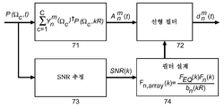
Figure 7 shows a block diagram for adaptive ambience processing in accordance with the present invention.
FIG. 8 is a block diagram of a noise-reduction filter using conventional ambsonic decoding
FIG. 9 shows a block diagram of a noise-
Sphere Microphone Array Processing - Ambi Sonics Theory
Ambisonic decoding is defined by assuming a loudspeaker that emits a sound field of a planar wave (MA Poletti, " Three-Dimensional Surround Sound Systems Based on Spherical Harmonics ", Journal of Audio Engineering Society, vol.53, no.11, pages 1004-1025, 2005).
![]()
The arrangement of the L loudspeakers is based on Ambi Sonics coefficients (
![]()
Where f is the frequency,
Decoding coefficients (
Ambisonics coefficients (
![]()
For the assumption of loudspeakers emitting a sound field of a planar wave, the coefficients of the planar wave (
Spherical harmonics satisfy the following equation as orthonormal basis functions of Ambisonics expressions.
![]()
here
![]()
The spherical microphone array samples the pressure on the spherical surface, where the number of sampling points is the number of ambience coefficients
Optimal sampling points (
![]()
here,
To achieve stable results for non-optimal sampling points, the conjugate complex spherical harmonics
![]()
In the following,
![]()
here,
Wherein the spherical microphone array has capsules substantially evenly distributed on the surface of the sphere and the number of capsules is
![]()
Sphere Microphone Array Processing - Simulation of Processing
The entire HOA processing chain for spherical microphone arrays on a rigid sphere (rigid and fixed) includes pressure estimation in the capsule, calculation of HOA coefficients, and decoding for loudspeaker weights. The description of the microphone array in the spherical harmonic representation enables estimation of the average spectral power at the origin for a given decoder. The power for the mode matching ambi Sonic decoder and the simple beamforming decoder is evaluated. The estimated average power at the sweet spot is used to design the equalization filter.
The next section
Sphere Microphone Array Processing - Simulation of Capsule Signals
The transfer function of the impinging planar wave for the microphone array on the surface of the steel body is described in M.A. It is defined by the following equation in Equation 19 of Section 2.2 of the Poletti paper.

here,
Accordingly,

Isotropic noise signal (
The pressure depends on the maximum degree of microphone array (

Sphere Microphone Array Processing - Ambsonics Encoding
Ambisonics coefficients (

Ambisonics coefficients (
Spherical Microphone Array Processing - Ambsonics Decoding
The optimization is based on the final loudspeaker weight at the origin

As can be seen from equation (14b)
In decoding, the reference coefficients may be of the order

The final weight of the noise signal (
![]()
From Equation (14a) to Equation (12b)

The resulting aliasing weight (
Simulations of aliased weights require ambsonic orders to represent capsule signals with sufficient accuracy. In Equation 14 of section 2.2.2 of the Moreau / Daniel / Bertet paper mentioned above, an analysis of the truncation error for the reconstruction of the Ambsonics sound field is given. The following equations will be described.
![]()
A reasonable accuracy of the sound field can be obtained,
![]()
As a result, accuracy at the upper frequency limit is acceptable, and accuracy increases even at lower frequencies.
Sphere Microphone Array Processing - Analysis of Loudspeaker Weights
Figure 1 shows a microphone array having 32 capsules on a rigid body,
Baseline weight (
Two error signals (
In the first step, the mean square error between the reference weight and the distorted reference weight is minimized for all entry plane wave directions. After being limited in space by the degree of Ambisonic representation
In the second step, the average power of the reconstructed weight is estimated for all plane wave directions. Hereinafter, a filter for balancing the power of the reconstructed weight to the power of the reference weight is described. These filters equalize power only at the sweet spot. However, the aliasing error still hinders the sound field representation for high frequencies.
The spatial frequency limit of the microphone array is referred to as the spatial aliasing frequency. The spatial aliasing frequency is calculated from the distance of the capsules (see WO 03/061336 A1) by the following equation
![]()
Here, the radius (
Optimization - Noise Reduction
Noise reduction is described in the above-mentioned European application with the internal reference number PD110039, where the signal-to-noise ratio between the average sound field power and the transducer noise

Transfer function (
Optimized weights (

Optimization - Spectral Power Equalization
Optimized weights (

Optimized error weights (
The resulting power depends on the decoding processing used. However, in the case of conventional three-dimensional ambsonic decoding, it is assumed that all directions are covered by the loudspeaker array. In this case, coefficients having a degree greater than 0 may be calculated using the decoding coefficients (
This is different for beamforming of Ambisonics representation because only sound from a particular direction is reconstructed. From here,
This is the order (

The derivation of equation (24) is provided in the above-mentioned European application with the internal reference number PD110039. Power
However, for ambsonic decoding, all loudspeaker decoding coefficients (
Obtained from the noise-optimized filter
Figure 4
now,
In the case of conventional ambisonic decoding,
![]()
However, it should be ensured that applied Ambisonics decoders will almost fulfill this assumption.
The real-valued equalization filter (

![]()
The problem is that the filter (

As described in equation (28d)
Optimization - Optimized Ambison processing
In an actual implementation of AmbiSonics microphone array processing, optimized Ambisonics coefficients (

This means that the capsules (
In the second processing step, the optimized transfer function of equation (30) is the first ambsonic representation

Transfer function (
As a result, the second processing step is performed with the designed time domain filter
Coefficients (
Alternatively, the linear filter may be approximated by a FIR filter, which transforms the coefficients of the FIR filter into the time domain using an inverse FFT, performs a cyclic shift, applies a tapering window to the final filter impulse response, By smoothing the function, the transfer function (
The adaptive block-based ambience processing of the present invention is illustrated in FIG. In the upper signal path, the time domain pressure signals of the microphone capsule signals (
The results of the processing of the present invention are described as follows. Thus, the equalization filter (< RTI ID = 0.0 >
The power of the reference weight and the power of the optimization weight are the same, whereby the final weight has a balanced wave spectrum. At low frequencies, the final signal-to-noise ratio at the sweet spot is given by
In addition, the final SRS is used for the decoding coefficients (< RTI ID = 0.0 >
There are other methods for optimized beam shaping that minimize the final SNR, where decoding coefficients (
The exemplary Ambisonic decoder uses mode matching processing, and each loudspeaker weight is calculated from the decoding coefficients used in the beamforming example. Because the loudspeakers are evenly distributed over the sphere surface
According to the results, the above-described optimization produces a balanced frequency spectrum with an increased SNR at the origin for a conventional Ambison decoder, i.e. the inventive time-variant adaptive filter design is advantageous for Ambsonic recording. The processing of the present invention may be used to design a time-varying filter assuming that the SNR of the recording is constant over time.
For beamforming decoders, the inventive processing can balance the final frequency spectrum with disadvantages of low SNR at low frequencies. The SNR can be increased by selecting appropriate decoding coefficients to produce broad beams, or by adapting the beam width to ambsonic orders of different frequency sub-bands.
The present invention can be applied to all of the concave microphone recordings in spherical harmonic representation where the reproduced spectral power at the origin is unbalanced by aliasing or omitting spherical harmonic coefficients.
Claims (10)
Wherein the microphone capsule signals indicative of the pressure on the surface of the microphone array are combined with directional coefficients to provide a spherical harmonic or Ambsonic representation
The average source power of the planar wave recorded from the microphone array
Using the reference, aliasing, and noise signal power components, the average spatial signal power at the origin for the diffuse sound field is multiplied by the wave number (
Using the linear filter processing the adaptive transfer function (< RTI ID = 0.0 >
The transfer function of the array (
Using the Fast Fourier transform (FFT), the spherical harmonic or ambsonic representation
Directional time domain coefficients (
Lt; / RTI >
Performing an inverse FFT;
Performing a cyclic shift;
Applying a tapering window to the final filter impulse response to smoothing the corresponding transfer function;
/ RTI >

Lt; / RTI >
Wherein the microphone capsule signals indicative of the pressure on the surface of the microphone array are combined with directional coefficients to provide a spherical harmonic or Ambsonic representation
The average source power of the planar wave recorded from the microphone array
Using the reference, aliasing, and noise signal power components, the average spatial signal power at the origin for the diffuse sound field is multiplied by the wave number (
Using the linear filter processing the adaptive transfer function (< RTI ID = 0.0 >
The transfer function of the array (
Using the Fast Fourier transform (FFT), the spherical harmonic or ambsonic representation
Directional time domain coefficients (
/ RTI >
Performing an inverse FFT;
Performing a cyclic shift;
Applying a tapering window to the final filter impulse response to smoothing the corresponding transfer function;
/ RTI >

Lt; / RTI >
Applications Claiming Priority (3)
| Application Number | Priority Date | Filing Date | Title |
|---|---|---|---|
| EP11306472.9A EP2592846A1 (en) | 2011-11-11 | 2011-11-11 | Method and apparatus for processing signals of a spherical microphone array on a rigid sphere used for generating an Ambisonics representation of the sound field |
| EP11306472.9 | 2011-11-11 | ||
| PCT/EP2012/071537 WO2013068284A1 (en) | 2011-11-11 | 2012-10-31 | Method and apparatus for processing signals of a spherical microphone array on a rigid sphere used for generating an ambisonics representation of the sound field |
Publications (2)
| Publication Number | Publication Date |
|---|---|
| KR20140089601A KR20140089601A (en) | 2014-07-15 |
| KR101957544B1 true KR101957544B1 (en) | 2019-03-12 |
Family
ID=47216219
Family Applications (1)
| Application Number | Title | Priority Date | Filing Date |
|---|---|---|---|
| KR1020147015683A KR101957544B1 (en) | 2011-11-11 | 2012-10-31 | Method and apparatus for processing signals of a spherical microphone array on a rigid sphere used for generating an ambisonics representation of the sound field |
Country Status (6)
| Country | Link |
|---|---|
| US (1) | US9420372B2 (en) |
| EP (2) | EP2592846A1 (en) |
| JP (1) | JP6113739B2 (en) |
| KR (1) | KR101957544B1 (en) |
| CN (1) | CN104041074B (en) |
| WO (1) | WO2013068284A1 (en) |
Families Citing this family (32)
| Publication number | Priority date | Publication date | Assignee | Title |
|---|---|---|---|---|
| US10021508B2 (en) | 2011-11-11 | 2018-07-10 | Dolby Laboratories Licensing Corporation | Method and apparatus for processing signals of a spherical microphone array on a rigid sphere used for generating an ambisonics representation of the sound field |
| EP2592845A1 (en) * | 2011-11-11 | 2013-05-15 | Thomson Licensing | Method and Apparatus for processing signals of a spherical microphone array on a rigid sphere used for generating an Ambisonics representation of the sound field |
| US9466305B2 (en) | 2013-05-29 | 2016-10-11 | Qualcomm Incorporated | Performing positional analysis to code spherical harmonic coefficients |
| US20140355769A1 (en) | 2013-05-29 | 2014-12-04 | Qualcomm Incorporated | Energy preservation for decomposed representations of a sound field |
| WO2015010850A2 (en) * | 2013-07-22 | 2015-01-29 | Brüel & Kjær Sound & Vibration Measurement A/S | Wide-band acoustic holography |
| US20150127354A1 (en) * | 2013-10-03 | 2015-05-07 | Qualcomm Incorporated | Near field compensation for decomposed representations of a sound field |
| EP2863654B1 (en) * | 2013-10-17 | 2018-08-01 | Oticon A/s | A method for reproducing an acoustical sound field |
| EP2879408A1 (en) * | 2013-11-28 | 2015-06-03 | Thomson Licensing | Method and apparatus for higher order ambisonics encoding and decoding using singular value decomposition |
| WO2015101915A2 (en) | 2013-12-31 | 2015-07-09 | Distran Gmbh | Acoustic transducer array device |
| US9922656B2 (en) | 2014-01-30 | 2018-03-20 | Qualcomm Incorporated | Transitioning of ambient higher-order ambisonic coefficients |
| US9502045B2 (en) | 2014-01-30 | 2016-11-22 | Qualcomm Incorporated | Coding independent frames of ambient higher-order ambisonic coefficients |
| US9852737B2 (en) * | 2014-05-16 | 2017-12-26 | Qualcomm Incorporated | Coding vectors decomposed from higher-order ambisonics audio signals |
| US9620137B2 (en) | 2014-05-16 | 2017-04-11 | Qualcomm Incorporated | Determining between scalar and vector quantization in higher order ambisonic coefficients |
| US10770087B2 (en) | 2014-05-16 | 2020-09-08 | Qualcomm Incorporated | Selecting codebooks for coding vectors decomposed from higher-order ambisonic audio signals |
| US20150332682A1 (en) * | 2014-05-16 | 2015-11-19 | Qualcomm Incorporated | Spatial relation coding for higher order ambisonic coefficients |
| EP2988527A1 (en) | 2014-08-21 | 2016-02-24 | Patents Factory Ltd. Sp. z o.o. | System and method for detecting location of sound sources in a three-dimensional space |
| US9747910B2 (en) | 2014-09-26 | 2017-08-29 | Qualcomm Incorporated | Switching between predictive and non-predictive quantization techniques in a higher order ambisonics (HOA) framework |
| CN105072557B (en) * | 2015-08-11 | 2017-04-19 | 北京大学 | Loudspeaker environment self-adaptation calibrating method of three-dimensional surround playback system |
| JP6606784B2 (en) * | 2015-09-29 | 2019-11-20 | 本田技研工業株式会社 | Audio processing apparatus and audio processing method |
| US10206040B2 (en) | 2015-10-30 | 2019-02-12 | Essential Products, Inc. | Microphone array for generating virtual sound field |
| CN112218211B (en) | 2016-03-15 | 2022-06-07 | 弗劳恩霍夫应用研究促进协会 | Apparatus, method or computer program for generating a sound field description |
| US11218807B2 (en) | 2016-09-13 | 2022-01-04 | VisiSonics Corporation | Audio signal processor and generator |
| WO2018064296A1 (en) * | 2016-09-29 | 2018-04-05 | Dolby Laboratories Licensing Corporation | Method, systems and apparatus for determining audio representation(s) of one or more audio sources |
| FR3060830A1 (en) * | 2016-12-21 | 2018-06-22 | Orange | SUB-BAND PROCESSING OF REAL AMBASSIC CONTENT FOR PERFECTIONAL DECODING |
| WO2018157098A1 (en) * | 2017-02-27 | 2018-08-30 | Essential Products, Inc. | Microphone array for generating virtual sound field |
| CN110771181B (en) * | 2017-05-15 | 2021-09-28 | 杜比实验室特许公司 | Method, system and device for converting a spatial audio format into a loudspeaker signal |
| JP7190279B2 (en) | 2018-08-10 | 2022-12-15 | 三栄源エフ・エフ・アイ株式会社 | cheese sauce |
| CN109275084B (en) * | 2018-09-12 | 2021-01-01 | 北京小米智能科技有限公司 | Method, device, system, equipment and storage medium for testing microphone array |
| JP6969793B2 (en) | 2018-10-04 | 2021-11-24 | 株式会社ズーム | A / B format converter for Ambisonics, A / B format converter software, recorder, playback software |
| CN111193990B (en) * | 2020-01-06 | 2021-01-19 | 北京大学 | 3D audio system capable of resisting high-frequency spatial aliasing and implementation method |
| US11489505B2 (en) | 2020-08-10 | 2022-11-01 | Cirrus Logic, Inc. | Methods and systems for equalization |
| CN115002640A (en) * | 2021-10-21 | 2022-09-02 | 杭州爱华智能科技有限公司 | Sound field characteristic conversion method of microphone and capacitive type test microphone system |
Citations (1)
| Publication number | Priority date | Publication date | Assignee | Title |
|---|---|---|---|---|
| US20030016835A1 (en) | 2001-07-18 | 2003-01-23 | Elko Gary W. | Adaptive close-talking differential microphone array |
Family Cites Families (8)
| Publication number | Priority date | Publication date | Assignee | Title |
|---|---|---|---|---|
| US20030147539A1 (en) * | 2002-01-11 | 2003-08-07 | Mh Acoustics, Llc, A Delaware Corporation | Audio system based on at least second-order eigenbeams |
| US7558393B2 (en) * | 2003-03-18 | 2009-07-07 | Miller Iii Robert E | System and method for compatible 2D/3D (full sphere with height) surround sound reproduction |
| EP1737271A1 (en) * | 2005-06-23 | 2006-12-27 | AKG Acoustics GmbH | Array microphone |
| EP1931169A4 (en) * | 2005-09-02 | 2009-12-16 | Japan Adv Inst Science & Tech | Post filter for microphone array |
| GB0619825D0 (en) * | 2006-10-06 | 2006-11-15 | Craven Peter G | Microphone array |
| GB0906269D0 (en) * | 2009-04-09 | 2009-05-20 | Ntnu Technology Transfer As | Optimal modal beamformer for sensor arrays |
| EP2592845A1 (en) * | 2011-11-11 | 2013-05-15 | Thomson Licensing | Method and Apparatus for processing signals of a spherical microphone array on a rigid sphere used for generating an Ambisonics representation of the sound field |
| US9197962B2 (en) * | 2013-03-15 | 2015-11-24 | Mh Acoustics Llc | Polyhedral audio system based on at least second-order eigenbeams |
-
2011
- 2011-11-11 EP EP11306472.9A patent/EP2592846A1/en not_active Withdrawn
-
2012
- 2012-10-31 JP JP2014540396A patent/JP6113739B2/en active Active
- 2012-10-31 CN CN201280066109.4A patent/CN104041074B/en active Active
- 2012-10-31 WO PCT/EP2012/071537 patent/WO2013068284A1/en active Application Filing
- 2012-10-31 KR KR1020147015683A patent/KR101957544B1/en active IP Right Grant
- 2012-10-31 US US14/356,265 patent/US9420372B2/en active Active
- 2012-10-31 EP EP12788472.4A patent/EP2777298B1/en active Active
Patent Citations (1)
| Publication number | Priority date | Publication date | Assignee | Title |
|---|---|---|---|---|
| US20030016835A1 (en) | 2001-07-18 | 2003-01-23 | Elko Gary W. | Adaptive close-talking differential microphone array |
Also Published As
| Publication number | Publication date |
|---|---|
| KR20140089601A (en) | 2014-07-15 |
| EP2777298B1 (en) | 2016-03-16 |
| JP2014535232A (en) | 2014-12-25 |
| JP6113739B2 (en) | 2017-04-12 |
| US20140307894A1 (en) | 2014-10-16 |
| EP2777298A1 (en) | 2014-09-17 |
| US9420372B2 (en) | 2016-08-16 |
| WO2013068284A1 (en) | 2013-05-16 |
| CN104041074B (en) | 2017-04-12 |
| EP2592846A1 (en) | 2013-05-15 |
| CN104041074A (en) | 2014-09-10 |
Similar Documents
| Publication | Publication Date | Title |
|---|---|---|
| KR101957544B1 (en) | Method and apparatus for processing signals of a spherical microphone array on a rigid sphere used for generating an ambisonics representation of the sound field | |
| JP6030660B2 (en) | Method and apparatus for processing a spherical microphone array signal on a hard sphere used to generate an ambisonic representation of a sound field | |
| Betlehem et al. | Theory and design of sound field reproduction in reverberant rooms | |
| US9113281B2 (en) | Reconstruction of a recorded sound field | |
| Ahrens et al. | An analytical approach to sound field reproduction using circular and spherical loudspeaker distributions | |
| EP2747449B1 (en) | Sound capture system | |
| KR101834913B1 (en) | Signal processing apparatus, method and computer readable storage medium for dereverberating a number of input audio signals | |
| KR20140138907A (en) | A method of applying a combined or hybrid sound -field control strategy | |
| KR101961261B1 (en) | Computationally efficient broadband filter-and-sum array focusing | |
| Sakamoto et al. | Sound-space recording and binaural presentation system based on a 252-channel microphone array | |
| KR20130102566A (en) | Spectrally uncolored optimal crosstalk cancellation for audio through loudspeakers | |
| Tylka et al. | Fundamentals of a parametric method for virtual navigation within an array of ambisonics microphones | |
| US10021508B2 (en) | Method and apparatus for processing signals of a spherical microphone array on a rigid sphere used for generating an ambisonics representation of the sound field | |
| JP2013113866A (en) | Reverberation removal method, reverberation removal device and program | |
| Marschall et al. | Sound-field reconstruction performance of a mixed-order ambisonics microphone array | |
| Kordon et al. | Optimization of spherical microphone array recordings | |
| Moore et al. | Processing pipelines for efficient, physically-accurate simulation of microphone array signals in dynamic sound scenes | |
| JP2013255155A (en) | Multichannel echo cancellation device and multichannel echo cancellation method and program | |
| Kashiwazaki et al. | Attempt to improve the total performance of sound field reproduction system: Integration of wave-based methods and simple reproduction method | |
| Pedamallu | Microphone Array Wiener Beamforming with emphasis on Reverberation | |
| Amerineni | Multi Channel Sub Band Wiener Beamformer | |
| Lokki et al. | Spatial Sound and Virtual Acoustics |
Legal Events
| Date | Code | Title | Description |
|---|---|---|---|
| E902 | Notification of reason for refusal | ||
| E701 | Decision to grant or registration of patent right | ||
| GRNT | Written decision to grant |