US10021508B2 - Method and apparatus for processing signals of a spherical microphone array on a rigid sphere used for generating an ambisonics representation of the sound field - Google Patents
Method and apparatus for processing signals of a spherical microphone array on a rigid sphere used for generating an ambisonics representation of the sound field Download PDFInfo
- Publication number
- US10021508B2 US10021508B2 US15/357,810 US201615357810A US10021508B2 US 10021508 B2 US10021508 B2 US 10021508B2 US 201615357810 A US201615357810 A US 201615357810A US 10021508 B2 US10021508 B2 US 10021508B2
- Authority
- US
- United States
- Prior art keywords
- spherical
- microphone
- ambisonics
- noise
- transfer function
- Prior art date
- Legal status (The legal status is an assumption and is not a legal conclusion. Google has not performed a legal analysis and makes no representation as to the accuracy of the status listed.)
- Active
Links
Images
Classifications
-
- H—ELECTRICITY
- H04—ELECTRIC COMMUNICATION TECHNIQUE
- H04S—STEREOPHONIC SYSTEMS
- H04S7/00—Indicating arrangements; Control arrangements, e.g. balance control
- H04S7/30—Control circuits for electronic adaptation of the sound field
- H04S7/307—Frequency adjustment, e.g. tone control
-
- H—ELECTRICITY
- H04—ELECTRIC COMMUNICATION TECHNIQUE
- H04R—LOUDSPEAKERS, MICROPHONES, GRAMOPHONE PICK-UPS OR LIKE ACOUSTIC ELECTROMECHANICAL TRANSDUCERS; DEAF-AID SETS; PUBLIC ADDRESS SYSTEMS
- H04R3/00—Circuits for transducers, loudspeakers or microphones
- H04R3/005—Circuits for transducers, loudspeakers or microphones for combining the signals of two or more microphones
-
- H—ELECTRICITY
- H04—ELECTRIC COMMUNICATION TECHNIQUE
- H04R—LOUDSPEAKERS, MICROPHONES, GRAMOPHONE PICK-UPS OR LIKE ACOUSTIC ELECTROMECHANICAL TRANSDUCERS; DEAF-AID SETS; PUBLIC ADDRESS SYSTEMS
- H04R1/00—Details of transducers, loudspeakers or microphones
- H04R1/20—Arrangements for obtaining desired frequency or directional characteristics
- H04R1/32—Arrangements for obtaining desired frequency or directional characteristics for obtaining desired directional characteristic only
- H04R1/326—Arrangements for obtaining desired frequency or directional characteristics for obtaining desired directional characteristic only for microphones
-
- H—ELECTRICITY
- H04—ELECTRIC COMMUNICATION TECHNIQUE
- H04R—LOUDSPEAKERS, MICROPHONES, GRAMOPHONE PICK-UPS OR LIKE ACOUSTIC ELECTROMECHANICAL TRANSDUCERS; DEAF-AID SETS; PUBLIC ADDRESS SYSTEMS
- H04R1/00—Details of transducers, loudspeakers or microphones
- H04R1/20—Arrangements for obtaining desired frequency or directional characteristics
- H04R1/32—Arrangements for obtaining desired frequency or directional characteristics for obtaining desired directional characteristic only
- H04R1/40—Arrangements for obtaining desired frequency or directional characteristics for obtaining desired directional characteristic only by combining a number of identical transducers
- H04R1/406—Arrangements for obtaining desired frequency or directional characteristics for obtaining desired directional characteristic only by combining a number of identical transducers microphones
-
- H—ELECTRICITY
- H04—ELECTRIC COMMUNICATION TECHNIQUE
- H04R—LOUDSPEAKERS, MICROPHONES, GRAMOPHONE PICK-UPS OR LIKE ACOUSTIC ELECTROMECHANICAL TRANSDUCERS; DEAF-AID SETS; PUBLIC ADDRESS SYSTEMS
- H04R2201/00—Details of transducers, loudspeakers or microphones covered by H04R1/00 but not provided for in any of its subgroups
- H04R2201/40—Details of arrangements for obtaining desired directional characteristic by combining a number of identical transducers covered by H04R1/40 but not provided for in any of its subgroups
- H04R2201/401—2D or 3D arrays of transducers
-
- H—ELECTRICITY
- H04—ELECTRIC COMMUNICATION TECHNIQUE
- H04R—LOUDSPEAKERS, MICROPHONES, GRAMOPHONE PICK-UPS OR LIKE ACOUSTIC ELECTROMECHANICAL TRANSDUCERS; DEAF-AID SETS; PUBLIC ADDRESS SYSTEMS
- H04R29/00—Monitoring arrangements; Testing arrangements
- H04R29/004—Monitoring arrangements; Testing arrangements for microphones
- H04R29/005—Microphone arrays
-
- H—ELECTRICITY
- H04—ELECTRIC COMMUNICATION TECHNIQUE
- H04R—LOUDSPEAKERS, MICROPHONES, GRAMOPHONE PICK-UPS OR LIKE ACOUSTIC ELECTROMECHANICAL TRANSDUCERS; DEAF-AID SETS; PUBLIC ADDRESS SYSTEMS
- H04R5/00—Stereophonic arrangements
- H04R5/027—Spatial or constructional arrangements of microphones, e.g. in dummy heads
-
- H—ELECTRICITY
- H04—ELECTRIC COMMUNICATION TECHNIQUE
- H04S—STEREOPHONIC SYSTEMS
- H04S2400/00—Details of stereophonic systems covered by H04S but not provided for in its groups
- H04S2400/15—Aspects of sound capture and related signal processing for recording or reproduction
-
- H—ELECTRICITY
- H04—ELECTRIC COMMUNICATION TECHNIQUE
- H04S—STEREOPHONIC SYSTEMS
- H04S2420/00—Techniques used stereophonic systems covered by H04S but not provided for in its groups
- H04S2420/11—Application of ambisonics in stereophonic audio systems
-
- H—ELECTRICITY
- H04—ELECTRIC COMMUNICATION TECHNIQUE
- H04S—STEREOPHONIC SYSTEMS
- H04S3/00—Systems employing more than two channels, e.g. quadraphonic
- H04S3/002—Non-adaptive circuits, e.g. manually adjustable or static, for enhancing the sound image or the spatial distribution
Definitions
- the invention relates to a method and to an apparatus for processing signals of a spherical microphone array on a rigid sphere used for generating an Ambisonics representation of the sound field, wherein a correction filter is applied to the inverse microphone array response.
- Spherical microphone arrays offer the ability to capture a three-dimensional sound field.
- One way to store and process the sound field is the Ambisonics representation.
- Ambisonics uses orthonormal spherical functions for describing the sound field in the area around the point of origin, also known as the sweet spot. The accuracy of that description is determined by the Ambisonics order N, where a finite number of Ambisonics coefficients describes the sound field.
- Ambisonics representation is that the reproduction of the sound field can be adapted individually to any given loudspeaker arrangement. Furthermore, this representation enables the simulation of different microphone characteristics using beam forming techniques at the post production.
- the B-format is one known example of Ambisonics.
- a B-format microphone requires four capsules on a tetrahedron to capture the sound field with an Ambisonics order of one.
- Ambisonics of an order greater than one is called Higher Order Ambisonics (HOA), and HOA microphones are typically spherical microphone arrays on a rigid sphere, for example the Eigenmike of mhAcoustics.
- HOA Higher Order Ambisonics
- the pressure distribution on the surface of the sphere is sampled by the capsules of the array.
- the sampled pressure is then converted to the Ambisonics representation.
- Such Ambisonics representation describes the sound field, but including the impact of the microphone array.
- the impact of the microphones on the captured sound field is removed using the inverse microphone array response, which transforms the sound field of a plane wave to the pressure measured at the microphone capsules. It simulates the directivity of the capsules and the interference of the microphone array with the sound field.
- the equalisation of the transfer function of the microphone array is a big problem for HOA recordings. If the Ambisonics representation of the array response is known, the impact can be removed by the multiplication of the Ambisonics representation with the inverse array response. However, using the reciprocal of the transfer function can cause high gains for small values and zeros in the transfer function. Therefore, the microphone array should be designed in view of a robust inverse transfer function. For example, a B-format microphone uses cardioid capsules to overcome the zeros in the transfer function of omni-directional capsules.
- the invention is related to spherical microphone arrays on a rigid sphere.
- the shading effect of the rigid sphere enables a good directivity for frequencies with a small wavelength with respect to the diameter of the array.
- the filter responses of these microphone arrays have very small values for low frequencies and high Ambisonics orders (i.e. greater than one).
- the Ambisonics representation of the captured pressure has therefore small higher order coefficients, which represent the small pressure difference at the capsules for wave lengths that are long when compared to the size of the array.
- the pressure differences, and therefore also the higher order coefficients are affected by the transducer noise.
- the inverse filter response amplifies mainly the noise instead of the higher order Ambisonics coefficients.
- a known technique for overcoming this problem is to fade out (or high pass filter) the high orders for low frequencies (i.e. to limit there the filter gain), which on one hand decreases the spatial resolution for low frequencies but on the other hand removes (highly distorted) HOA coefficients, thereby corrupting the complete Ambisonics representation.
- a corresponding compensation filter design that tries to solve this problem using Tikhonov regularisation filters is described in Sébastien Moreau, Jérnies Daniel, Stéphanie Bertet, “3D Sound field Recording with Higher Order Ambisonics—Objective Measurements and Validation of a 4th Order Spherical Microphone”, Audio Engineering Society convention paper, 120th Convention 20-23 May 2006, Paris, France, in section 4.
- a Tikhonov regularisation filter minimises the squared error resulting from the limitation of the Ambisonics order.
- the Tikhonov filter requires a regularisation parameter that has to be adapted manually to the characteristics of the recorded signal by ‘trial and error’, and there is no analytic expression defining this parameter.
- the invention Based on the analysis of spherical microphone arrays of Boaz Rafaely, “Analysis and Design of Spherical Microphone Arrays”, IEEE Transactions on Speech and Audio Processing, vol. 13, no. 1, pages 135-143, 2005, the invention shows how to obtain automatically the regularisation parameter from the signal statistics of the microphone signals.
- a problem to be solved by the invention is to minimise noise, in particular low frequency noise, in an Ambisonics representation of the signals of a spherical microphone array arranged on a rigid sphere.
- This problem is solved by the method disclosed in claim 1 .
- An apparatus that utilises this method is disclosed in claim 2 .
- the inventive processing is used for computing the regularisation Tikhonov parameter in dependence of the signal-to-noise ratio of the average sound field power and the noise power of the microphone capsules, i.e. that optimisation parameter is computed from the signal-to-noise ratio of the recorded microphone array signals.
- the computation of the optimisation or regularisation parameter includes the following steps:
- the filter design requires an estimation of the average power of the sound field in order to obtain the SNR of the recording.
- the estimation is derived from the simulation of the average signal power at the capsules of the array in the spherical harmonics representation.
- This estimation includes the computation of the spatial coherence of the capsule signal in the spherical harmonics representation. It is known to compute the spatial coherence from the continuous representation of a plane wave, but according to the invention the spatial coherence is computed for a spherical array on a rigid sphere, because the sound field of a plane wave on the rigid sphere cannot be computed in the continuous representation, i.e., according to the invention the SNR is estimated from the capsule signals.
- the inventive method is suited for processing microphone capsule signals of a spherical microphone array on a rigid sphere, said method including the steps:
- the inventive apparatus is suited for processing microphone capsule signals of a spherical microphone array on a rigid sphere, said apparatus including:
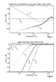
- FIG. 1 power of reference, aliasing and noise components from the resulting loudspeaker weight for a microphone array with 32 capsules on a rigid sphere;
- FIG. 3 block diagram for a block-based adaptive Ambisonics processing
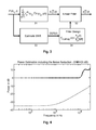
- FIG. 4 average power of weight components following the optimisation filter of FIG. 2 .
- the arrangement of L loudspeakers reconstructs the three-dimensional sound field stored in the Ambisonics coefficients d n m (k). The processing is carried out separately for each wave number
- index n runs from 0 to the finite order N, whereas index m runs from ⁇ n to n for each index n.
- Equation (1) defines the conversion of the Ambisonics coefficients d n m (k) to the loudspeaker weights w( ⁇ l , k). These weights are the driving functions of the loudspeakers. The superposition of all speaker weights reconstructs the sound field.
- the decoding coefficients D n m ( ⁇ l ) are describing the general Ambisonics decoding processing. This includes the conjugated complex coefficients of a beam pattern as shown in section 3 ( ⁇ * nm ) in Morag Agmon, Boaz Rafaely, “Beamforming for a Spherical-Aperture Microphone”, IEEEI, pages 227-230, 2008, as well as the rows of the mode matching decoding matrix given in the above-mentioned M. A. Poletti article in section 3.2. A different way of processing, described in section 4 in Johann-Markus Batke, Florian Keiler, “Using VBAP-Derived Panning Functions for 3D Ambisonics Decoding”, Proc.
- the coefficients of a plane wave d n plane m (k) are defined for the assumption of loudspeakers that are radiating the sound field of a plane wave.
- the pressure at the point of origin is defined by P 0 (k) for the wave number k.
- the conjugated complex spherical harmonics Y n m ( ⁇ s )* denote the directional coefficients of a plane wave.
- the definition of the spherical harmonics Y n m ( ⁇ s ) given in the above-mentioned M. A. Po-letti article is used.
- the spherical harmonics are the orthonormal base functions of the Ambisonics representations and satisfy
- W is an additional weighting matrix to account for the non-uniformity of the microphone distribution.
- a hyperinterpolation scheme may be employed instead of quadrature or least squares.
- the nodes form a well-conditioned matrix Y such that
- a complete HOA processing chain for spherical microphone arrays on a rigid (stiff, fixed) sphere includes the estimation of the pressure at the capsules, the computation of the HOA coefficients and the decoding to the loudspeaker weights. It is based on that for a plane wave the reconstructed weight w(k) from the microphone array must be equal to the reconstructed reference weight w ref (k) from the coefficients of a plane wave, given in equation (3).
- the following section presents the decomposition of w(k) into the reference weight w ref (k), the spatial aliasing weight w alias (k) and a noise weight w noise (k).
- the aliasing is caused by the sampling of the continuous sound field for a finite order N and the noise simulates the spatially uncorrelated signal parts introduced for each capsule.
- the spatial aliasing cannot be removed for a given microphone array.
- h n (1) (kr) is the Hankel function of the first kind and the radius r is equal to the radius of the sphere R.
- the transfer function is derived from the physical principle of scattering the pressure on a rigid sphere, which means that the radial velocity vanishes on the surface of a rigid sphere. In other words, the superposition of the radial derivation of the incoming and the scattered sound field is zero, cf. section 6.10.3 of the “Fourier Acoustics” book.
- the isotropic noise signal P noise ( ⁇ c , k) is added to simulate transducer noise, where ‘isotropic’ means that the noise signals of the capsules are spatially uncorrelated, which does not include the correlation in the temporal domain.
- the pressure can be separated into the pressure P ref ( ⁇ c , kR) computed for the maximal order N of the microphone array and the pressure from the remaining orders, cf. section 7, equation (24) in the above-mentioned Rafaely “Analysis and design . . . ” article.
- the pressure from the remaining orders P alias ( ⁇ c , kR) is called the spatial aliasing pressure because the order of the microphone array is not sufficient to reconstruct these signal components.
- the total pressure recorded at the capsule c is defined by:
- the Ambisonics coefficients d n m (k) are obtained from the pressure at the capsules by the inversion of equation (12) given in equation (14a), cf. section 3.2.2, equation (26) of the above-mentioned Moreau/Daniel/Bertet article.
- the spherical harmonics Y n m ( ⁇ c ) is inverted by Y n m ( ⁇ c ) ⁇ using equation (8), and the transfer function b n (kR) is equalised by its inverse:
- the Ambisonics coefficients d n m (k) can be separated into the reference coefficients d n ref m (k), the aliasing coefficients d n alias m (k) and the noise coefficients d n noise m (k) using equations (14a) and (13a) as shown in equations (14b) and (14c).
- Equation (15) provides w(k) from equations (1) and (14b), where L is the number of loudspeakers:
- Equation (15b) shows that w(k) can also be separated into the three weights w ref (k), w alias (k) and w noise (k).
- w ref (k) the weights w ref (k)
- w alias (k) the weights w alias (k)
- w noise the positioning error given in section 7, equation (24) of the above-mentioned Rafaely “Analysis and design . . . ” article is not considered here.
- the reference coefficients are the weights that a synthetically generated plane wave of order n would create.
- the reference pressure P ref ( ⁇ c , kR) from equation (13b) is substituted in equation (15a), whereby the pressure signals P alias ( ⁇ c , kR) and P noise ( ⁇ c , k) are ignored (i.e. set to zero):
- Equation (16a) can be simplified to the sum of the weights of a plane wave in the Ambisonics representation from equation (3).
- equation (16a) can be simplified to the sum of the weights of a plane wave in the Ambisonics representation from equation (3).
- N max ⁇ 2 ⁇ ⁇ ⁇ ⁇ f max ⁇ R c sound ⁇ ( 20 ) is used for the simulation of the aliasing pressure of each wave number. This results in an acceptable accuracy at the upper frequency limit, and the accuracy even increases for low frequencies.
- the maximal Ambisonics order N supported by this array is four.
- the mode matching processing as described in the above-mentioned M. A.
- Poletti article is used to obtain the decoding coefficients D n m ( ⁇ l ) for 25 uniformly distributed loudspeaker positions according to Jorg Fliege, Ulrike Maier, “A Two-Stage Approach for Computing Cubature Formulae for the Sphere”, Technical report, 1996, für Schlauer Mathematik, Universitat Dortmund, Germany.
- the node numbers are shown at http://www.mathematik.uni-dortmund.de/lsx/research/projects/fliege/nodes/nodes.html.
- the reference power w ref (k) is constant over the entire frequency range.
- the resulting noise weight w noise (k) shows high power at low frequencies and decreases at higher frequencies.
- the noise signal or power is simulated by a normally distributed unbiased pseudo-random noise with a variance of 20 dB (i.e. 20 dB lower than the power of the plane wave).
- the aliasing noise w alias (k) can be ignored at low frequencies but increases with rising frequency, and above 10 kHz exceeds the reference power.
- the slope of the aliasing power curve depends on the plane wave direction. However, the average tendency is consistent for all directions.
- the two error signals w noise (k) and w alias (k) distort the reference weight in different frequency ranges. Furthermore, the error signals are independent of each other. Therefore it is proposed to minimise the noise signal without taking into account the alias signal.
- the mean square error between the reference weight and the distorted reference weight is minimised for all incoming plane wave directions.
- the weight from the aliasing signal w alias (k) is ignored because w alias (k) cannot be corrected after being spatially band-limited by the order of the Ambisonics representation. This is equivalent to the time domain aliasing where the aliasing cannot be removed from the sampled and band-limited time signal.
- the noise reduction minimises the mean squared error introduced by the noise signal.
- the Wiener filter processing is used in the frequency domain for computing the frequency response of the compensation filter for each order n.
- the error signal is obtained from the reference weight w ref (k) and the filtered and distorted weight w ref (k)+w noise (k) for each wave number k.
- the aliasing error w alias (k) is ignored here.
- the distorted weight is filtered by the optimisation transfer function F(k), where the processing is performed in the frequency domain by a multiplication of the distorted signal and the transfer function F(k).
- the zero phase transfer function F(k) is derived by minimising the expectation value of the squared error between the reference weight and the filtered and distorted weight:
- the expectation value E of the squared absolute weight denotes the average signal power of the weight. Therefore the fraction of the powers of w noise (k) and w ref (k) represents the reciprocal signal-to-noise ration of the reconstructed weights for each wave number k.
- the computation of the power of w noise (k) and w ref (k) is explained in the following section.
- Equation (24c) shows that the power is equal to the sum of the squared absolute HOA coefficients D n m ( ⁇ l ) added up over all loudspeakers. It is assumed that
- the restriction for the capsule positions is commonly fulfilled for spherical microphone arrays as the array should sample the pressure on the sphere uniformly.
- a constant noise power can always be assumed for the noise that is produced by the analog processing (e.g. sensor noise or amplification) and the analog-to-digital conversion for each microphone signal.
- the restrictions are valid for common spherical microphone arrays.
- the expectation value from equation (21b) is a linear superposition of the reference power and the noise power.
- the power of each weight can be separated to the sum of the power of each order n.
- the expectation value from equation (21b) can also be separated into a superposition for each order n.
- the transfer function F n (k) is obtained from the transfer function F(k) by combining equations (23), (24) and (25).
- the N+1 optimisation transfer functions are defined by
- the transfer function F n (k) depends on the number of capsules and the signal to noise ration for the wavenumber k:
- the transfer function is independent of the Ambisonics decoder, which means that it is valid for three-dimensional Ambisonics decoding and directional beam forming.
- the transfer function can also be derived from the mean squared error of the Ambisonics coefficients d n m (k) without taking the sum over the decoding coefficients D n m ( ⁇ l ) into account. Because the power
- the optimised weight w′(k) is computed from
- the reciprocal of the transfer function b n (kR) converts A n m (t) to the directional coefficients d n m (t), where it is assumed that the sampled sound field is created by a superposition of plane waves that were scattered on the surface of the sphere.
- the coefficients d n m (t) are representing the plane wave decomposition of the sound field described in section 3, equation (14) of the above-mentioned Rafaely “Plane-wave decomposition . . .
- the processing of the coefficients A n m (t) can be regarded as a linear filtering operation, where the transfer function of the filter is determined by F n,array (k). This can be performed in the frequency domain as well as in the time domain.
- the FFT can be used for transforming the coefficients A n m (t) to the frequency domain for the successive multiplication by the transfer function F n,array (k).
- the inverse FFT of the product results in the time domain coefficients d n m (t).
- This transfer function processing is also known as the fast convolution using the overlap-add or over-lap-save method.
- the linear filter can be approximated by an FIR filter, whose coefficients can be computed from the transfer function F n,array (k) by transforming it to the time domain with an inverse FFT, performing a circular shift and applying a tapering window to the resulting filter impulse response to smooth the corresponding transfer function.
- the linear filtering process is then performed in the time domain by a convolution of the time domain coefficients of the transfer function F n,array (k) and the coefficients A n m (t) for each combination of n and m.
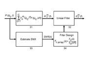
- the inventive adaptive block based Ambisonics processing is depicted in FIG. 3 .
- the time domain pressure signals P( ⁇ c , t) of the microphone capsule signals are converted in step or stage 31 to the Ambisonics representation A n m (t) using equation (14a), whereby the division by the microphone transfer function b n (kR) is not carried out (thereby A n m (t) is calculated instead of d n m (k)) and is instead carried out in step/stage 32 .
- Step/stage 32 performs then the described linear filtering operation in the time domain or frequency domain in order to obtain the coefficients d n m (t).
- the second processing path is used for an automatic adaptive filter design of the transfer function F n,array (k).
- the step/stage 33 performs the estimation of the signal-to-noise ratio SNR(k) for a considered time period (i.e. block of samples). The estimation is performed in the frequency domain for a finite number of discrete wavenumbers k. Thus the regarded pressure signals P( ⁇ c , t) have to be transformed to the frequency domain using for example an FFT.
- the SNR(k) value is specified by the two power signals
- 2 of the noise signal is constant for a given array and represents the noise produced by the capsules.
- 2 of the plane wave has to be estimated from the pressure signals P( ⁇ c , t).
- the estimation is further described in section SNR estimation.
- the transfer function F n,array (k) with n ⁇ N is designed in step/stage 34 .
- the filter design comprises the design of the Wiener filter given in equation (29c) and the inverse array response or inverse transfer function 1/b n (kR).
- the Wiener filter limits the high amplification of the transfer function of the inverse array response. This results in manageable amplifications of the transfer function F n,array (k).
- the filter implementation is then adapted to the corresponding linear filter processing in the time or frequency domain of step/stage 32 .
- the SNR(k) value is to be estimated from the recorded capsules signals: it depends on the average power of the plane wave
- the noise power is obtained from equation (26) in a silent environment without any sound sources so that
- 2 0 can be assumed.
- the noise power should be measured for several amplifier gains. The noise power can then be adapted to the used amplifier gain for several recordings.
- 2 is estimated from the pressure P mic ( ⁇ c , k) measured at the capsules. This is performed by a comparison of the expectation value of the pressure at the capsules from equation (13) and the measured average signal power at the capsules defined by
- the expectation value P sig (k) can also be estimated for the Ambisonics representation of the pressure at the capsules from equation (13) by:
- equation (36b) the orthonormal condition from equation (4) can be applied to the expansion of the absolute magnitude to derive equation (36c).
- the average signal power is estimated from the cross-correlation of the spherical harmonics Y n m ( ⁇ c ).
- this represents the coherence of the pressure field at the capsule positions.
- the equalisation of equations (35) and (36) obtains the estimation of
- the denominator from equation (37) is constant for each wave number k for a given microphone array. It can therefore be computed once for the Ambisonics order N max to be stored in a look-up table or store for each wave number k.
- the estimation of the average source power from the given capsule signals is also known from the linear microphone array processing.
- the cross-correlation of the capsule signal is called the spatial coherence of the sound field.
- the spatial coherence is determined from the continuous representation of the plane wave.
- the description of the scattered sound field on a rigid sphere is known only in the Ambisonics representation. Therefore, the presented estimation of the SNR(k) is based on a new processing that determines the spatial coherence on the surface of a rigid sphere.
- the average power components of w′(k) obtained from the optimisation filter of FIG. 2 are shown in FIG. 4 for a mode matching Ambisonics decoder.
- the noise power is reduced to ⁇ 35 dB up to a frequency of 1 kHz. Above 1 kHz the noise power increases linearly to ⁇ 10 dB.
- the total power is raised by 10 dB above 10 kHz, which is caused by the aliasing power. Above 10 kHz the HOA order of the microphone array does not sufficiently describe the pressure distribution on the surface for a sphere with a radius equal to R. Thus, the average power caused by the obtained Ambisonics coefficients is greater than the reference power.
Landscapes
- Physics & Mathematics (AREA)
- Engineering & Computer Science (AREA)
- Acoustics & Sound (AREA)
- Signal Processing (AREA)
- Health & Medical Sciences (AREA)
- General Health & Medical Sciences (AREA)
- Otolaryngology (AREA)
- Circuit For Audible Band Transducer (AREA)
- Obtaining Desirable Characteristics In Audible-Bandwidth Transducers (AREA)
- Stereophonic System (AREA)
Abstract
Description
-
- Converting the microphone capsule signals P(Ωc, t) representing the pressure on the surface of said microphone array to a spherical harmonics (or the equivalent Ambisonics) representation An m(t);
- Computing per wave number k an estimation of the time-variant signal-to-noise ratio SNR(k) of the microphone capsule signals P(Ωc, t), using the average source power |P0(k)|2 of the plane wave recorded from the microphone array and the corresponding noise power |Pnoise(k)|2 representing the spatially uncorrected noise produced by analog processing in the microphone array, i.e. including computing the average spatial power by computing separately a reference signal and a noise signal, wherein the reference signal is the representation of the sound field that can be created with the used microphone array, and the noise signal is the spatially uncorrelated noise produced by the analog processing of the microphone array.
- By using a time-variant Wiener filter for each order n designed at discrete finite wave numbers k from the signal-to-noise ratio estimation SNR(k), multiplying the transfer function of the Wiener filter by the inverse transfer function
of the microphone array in order to get an adapted transfer function Fn,array(k);
-
- Applying that adapted transfer function Fn,array(k) to the spherical harmonics representation An m(t) using a linear filter processing, resulting in adapted directional coefficients dn m(t).
-
- The order of the Ambisonics representation is optimally adapted to the SNR of the recording for each frequency sub-band. This reduces the audible noise at the reproduction of the Ambisonics representation.
- The estimation of the SNR is required for the filter design. It can be implemented with a low computational complexity by using look-up tables. This facilitates a time-variant adaptive filter design with manageable computational effort.
- By the noise reduction, the directional information is partly restored for low frequencies.
-
- converting said microphone capsule signals P(Ωc, t) representing the pressure on the surface of said microphone array to a spherical harmonics or Ambisonics representation An m(t);
- computing per wave number k an estimation of the time-variant signal-to-noise ratio SNR(k) of said microphone capsule signals P(Ωc, t), using the average source power |P0(k)|2 of the plane wave recorded from said microphone array and the corresponding noise power |Pnoise(k)|2 representing the spatially uncorrected noise produced by analog processing in said microphone array;
- by using a time-variant Wiener filter for each order n designed at discrete finite wave numbers k from said signal-to-noise ratio estimation SNR(k), multiplying the transfer function of said Wiener filter by the inverse transfer function of said microphone array in order to get an adapted transfer function Fn,array(k);
- applying said adapted transfer function Fn,array(k) to said spherical harmonics representation An m(t) using a linear filter processing, resulting in adapted directional coefficients dn m(t).
-
- means being adapted for converting said microphone capsule signals P(Ωc, t) representing the pressure on the surface of said microphone array to a spherical harmonics or Ambisonics representation An m(t);
- means being adapted for computing per wave number k an estimation of the time-variant signal-to-noise ratio SNR(k) of said microphone capsule signals P(Ωc, t), using the average source power |P0(k)|2 of the plane wave recorded from said microphone array and the corresponding noise power |Pnoise(k)|2 representing the spatially uncorrected noise produced by analog processing in said microphone array;
- means being adapted for multiplying, by using a time-variant Wiener filter for each order n designed at discrete finite wave numbers k from said signal-to-noise ratio estimation SNR(k), the transfer function of said Wiener filter by the inverse transfer function of said microphone array in order to get an adapted transfer function Fn,array(k);
- means being adapted for applying said adapted transfer function Fn,array(k) to said spherical harmonics representation An m(t) using a linear filter processing, resulting in adapted directional coefficients dn m(t).
w(Ωl ,k)=Σn=0 NΣm=−n n D n m(Ωl)d n m(k) (1)
where f is the frequency and csound is the speed of sound. Index n runs from 0 to the finite order N, whereas index m runs from −n to n for each index n. The total number of coefficients is therefore O=(N+1)2. The loudspeaker position is defined by the direction vector Ωl=[Θl, Φl]T in spherical coordinates, and [•]T denotes the transposed version of a vector.
d n
with n′≤N and n≤N for C≥(N+1)2, C being the total number of capsules, and wc being a set of weights to enable orthonormality of the sampled spherical harmonics.
Y †=(Y H WY)−1 Y H W
δn-n′δm-m′=Σc=1 c Y n m(Ωc)Y n′ m′(Ωc)† (8)
with n′≤N and n≤N for C≥(N+1)2.
becomes a valid expression. The substitution of (9) in (8) results in the orthonormal condition
with n′≤N and n≤N for C≥(N+1)2, which is to be considered below.
where Yn′ m′(Ωc)−1 are the columns of Y−1.
where hn (1)(kr) is the Hankel function of the first kind and the radius r is equal to the radius of the sphere R. The transfer function is derived from the physical principle of scattering the pressure on a rigid sphere, which means that the radial velocity vanishes on the surface of a rigid sphere. In other words, the superposition of the radial derivation of the incoming and the scattered sound field is zero, cf. section 6.10.3 of the “Fourier Acoustics” book.
P(Ω,kR)=Σn=0 ∞Σm=−n n b n(kR)Y n m(Ω)d n m(k)=Σn=0 ∞Σm=−n n b n(kR)Y n m(Ω)Y n m(Ωs)*P 0(k). (12)
Ambisonics Encoding
from equation (15a) and using only Pnoise(Ωc, k) from equation (13b).
N opt =┌kR┐ (19)
a reasonable accuracy of the sound field can be obtained, where ‘┌•┐’ denotes the rounding-up to the nearest integer. This accuracy is used for the upper frequency limit fmax of the simulation. Thus, the Ambisonics order of
is used for the simulation of the aliasing pressure of each wave number. This results in an acceptable accuracy at the upper frequency limit, and the accuracy even increases for low frequencies.
Analysis of the Loudspeaker Weight
for all capsules. Applying these restrictions, equation (25b) reduces to
E{|w ref(k)|2}−2F(k)E{|w ref(k)|2 }+F(k)2(E{|w ref(k)|2 }+E{|w noise(k)|2})≥Σn=0 N E n {|w ref(k)|2}−2F n(k)E n {|w ref(k)|2 }+F n(k)2(E n {|w ref(k)|2 }+E n {|w noise(k)|2}) (28)
from
minimises the average reconstruction error of the Ambisonics recording for a given SNR(k). The transfer functions Fn(k) are shown in
Optimised Ambisonics Processing
which includes the sum over the capsules c and an adaptive transfer function for each order n and wave number k. That sum converts the sampled pressure distribution on the surface of the sphere to the Ambisonics representation, and for wide-band signals it can be performed in the time domain. This processing step converts the time domain pressure signals P(Ωc, t) to the first Ambisonics representation An m(t).
reconstructs the directional information items from the first Ambisonics representation An m(t). The reciprocal of the transfer function bn(kR) converts An m(t) to the directional coefficients dn m(t), where it is assumed that the sampled sound field is created by a superposition of plane waves that were scattered on the surface of the sphere. The coefficients dn m(t) are representing the plane wave decomposition of the sound field described in
Claims (8)
Y †=(Y H WY)−1 Y H W
Y †=(Y H WY)−1 Y H W
Priority Applications (1)
| Application Number | Priority Date | Filing Date | Title |
|---|---|---|---|
| US15/357,810 US10021508B2 (en) | 2011-11-11 | 2016-11-21 | Method and apparatus for processing signals of a spherical microphone array on a rigid sphere used for generating an ambisonics representation of the sound field |
Applications Claiming Priority (6)
| Application Number | Priority Date | Filing Date | Title |
|---|---|---|---|
| EP11306471.1A EP2592845A1 (en) | 2011-11-11 | 2011-11-11 | Method and Apparatus for processing signals of a spherical microphone array on a rigid sphere used for generating an Ambisonics representation of the sound field |
| EP11306471.1 | 2011-11-11 | ||
| EP11306471 | 2011-11-11 | ||
| PCT/EP2012/071535 WO2013068283A1 (en) | 2011-11-11 | 2012-10-31 | Method and apparatus for processing signals of a spherical microphone array on a rigid sphere used for generating an ambisonics representation of the sound field |
| US201414356185A | 2014-05-05 | 2014-05-05 | |
| US15/357,810 US10021508B2 (en) | 2011-11-11 | 2016-11-21 | Method and apparatus for processing signals of a spherical microphone array on a rigid sphere used for generating an ambisonics representation of the sound field |
Related Parent Applications (2)
| Application Number | Title | Priority Date | Filing Date |
|---|---|---|---|
| US14/356,185 Continuation-In-Part US9503818B2 (en) | 2011-11-11 | 2012-10-31 | Method and apparatus for processing signals of a spherical microphone array on a rigid sphere used for generating an ambisonics representation of the sound field |
| PCT/EP2012/071535 Continuation-In-Part WO2013068283A1 (en) | 2011-11-11 | 2012-10-31 | Method and apparatus for processing signals of a spherical microphone array on a rigid sphere used for generating an ambisonics representation of the sound field |
Publications (2)
| Publication Number | Publication Date |
|---|---|
| US20170070840A1 US20170070840A1 (en) | 2017-03-09 |
| US10021508B2 true US10021508B2 (en) | 2018-07-10 |
Family
ID=58189710
Family Applications (1)
| Application Number | Title | Priority Date | Filing Date |
|---|---|---|---|
| US15/357,810 Active US10021508B2 (en) | 2011-11-11 | 2016-11-21 | Method and apparatus for processing signals of a spherical microphone array on a rigid sphere used for generating an ambisonics representation of the sound field |
Country Status (1)
| Country | Link |
|---|---|
| US (1) | US10021508B2 (en) |
Families Citing this family (3)
| Publication number | Priority date | Publication date | Assignee | Title |
|---|---|---|---|---|
| US10721559B2 (en) * | 2018-02-09 | 2020-07-21 | Dolby Laboratories Licensing Corporation | Methods, apparatus and systems for audio sound field capture |
| EP3809726A1 (en) * | 2019-10-17 | 2021-04-21 | Bang & Olufsen A/S | Echo based room estimation |
| TWI760833B (en) * | 2020-09-01 | 2022-04-11 | 瑞昱半導體股份有限公司 | Audio processing method for performing audio pass-through and related apparatus |
Citations (9)
| Publication number | Priority date | Publication date | Assignee | Title |
|---|---|---|---|---|
| US20030016835A1 (en) | 2001-07-18 | 2003-01-23 | Elko Gary W. | Adaptive close-talking differential microphone array |
| US20030147539A1 (en) | 2002-01-11 | 2003-08-07 | Mh Acoustics, Llc, A Delaware Corporation | Audio system based on at least second-order eigenbeams |
| US20040247134A1 (en) | 2003-03-18 | 2004-12-09 | Miller Robert E. | System and method for compatible 2D/3D (full sphere with height) surround sound reproduction |
| EP1931169A1 (en) | 2005-09-02 | 2008-06-11 | Japan Advanced Institute of Science and Technology | Post filter for microphone array |
| WO2011116153A1 (en) | 2010-03-18 | 2011-09-22 | Graco Minnesota Inc. | Light weight z-swivel |
| US20120093344A1 (en) | 2009-04-09 | 2012-04-19 | Ntnu Technology Transfer As | Optimal modal beamformer for sensor arrays |
| US20140270245A1 (en) | 2013-03-15 | 2014-09-18 | Mh Acoustics, Llc | Polyhedral audio system based on at least second-order eigenbeams |
| US20140307894A1 (en) | 2011-11-11 | 2014-10-16 | Thomson Licensing A Corporation | Method and apparatus for processing signals of a spherical microphone array on a rigid sphere used for generating an ambisonics representation of the sound field |
| US9503818B2 (en) * | 2011-11-11 | 2016-11-22 | Dolby Laboratories Licensing Corporation | Method and apparatus for processing signals of a spherical microphone array on a rigid sphere used for generating an ambisonics representation of the sound field |
-
2016
- 2016-11-21 US US15/357,810 patent/US10021508B2/en active Active
Patent Citations (10)
| Publication number | Priority date | Publication date | Assignee | Title |
|---|---|---|---|---|
| US20030016835A1 (en) | 2001-07-18 | 2003-01-23 | Elko Gary W. | Adaptive close-talking differential microphone array |
| US20030147539A1 (en) | 2002-01-11 | 2003-08-07 | Mh Acoustics, Llc, A Delaware Corporation | Audio system based on at least second-order eigenbeams |
| US20100008517A1 (en) | 2002-01-11 | 2010-01-14 | Mh Acoustics,Llc | Audio system based on at least second-order eigenbeams |
| US20040247134A1 (en) | 2003-03-18 | 2004-12-09 | Miller Robert E. | System and method for compatible 2D/3D (full sphere with height) surround sound reproduction |
| EP1931169A1 (en) | 2005-09-02 | 2008-06-11 | Japan Advanced Institute of Science and Technology | Post filter for microphone array |
| US20120093344A1 (en) | 2009-04-09 | 2012-04-19 | Ntnu Technology Transfer As | Optimal modal beamformer for sensor arrays |
| WO2011116153A1 (en) | 2010-03-18 | 2011-09-22 | Graco Minnesota Inc. | Light weight z-swivel |
| US20140307894A1 (en) | 2011-11-11 | 2014-10-16 | Thomson Licensing A Corporation | Method and apparatus for processing signals of a spherical microphone array on a rigid sphere used for generating an ambisonics representation of the sound field |
| US9503818B2 (en) * | 2011-11-11 | 2016-11-22 | Dolby Laboratories Licensing Corporation | Method and apparatus for processing signals of a spherical microphone array on a rigid sphere used for generating an ambisonics representation of the sound field |
| US20140270245A1 (en) | 2013-03-15 | 2014-09-18 | Mh Acoustics, Llc | Polyhedral audio system based on at least second-order eigenbeams |
Non-Patent Citations (12)
| Title |
|---|
| Agmon, M. et al "Beamforming for a Spherical-Aperture Microphone" IEEE , pp. 227-230, 2008. |
| Anonymous, "Eigenmike", mh acoustics, Homepage, online retrieved from: http:www.mhacoustics.com, viewed on: Feb. 1, 2007. |
| Batke, Johann-Markus, et al "Using VBAP-Derived Panning Functions for 3D Ambisonics Decoding" Proc. of the 2nd International Symposium on Ambisonics and Spherical Acoustics, May 6-7, 2010, Paris, France, pp. 1-4. |
| Fliege, J. et al "A Two-Stage Approach for Computing a Cubature Formulate for the Sphere" Technical report, Fachbereich Mathemarik, Universitat Dortmunt, 1999, Dortmund/Germany, pp. 1-32. |
| Moreau, S. et al "3D Sound Field Recording with Higher Order Ambisonics-Objective Measurements and Validation of Spherical Microphone" AES presented at the 120th convention, May 20-23, 2006, Paris France, pp. 1-24. |
| Moreau, S. et al "3D Sound Field Recording with Higher Order Ambisonics—Objective Measurements and Validation of Spherical Microphone" AES presented at the 120th convention, May 20-23, 2006, Paris France, pp. 1-24. |
| Poletti, M.A. "Three-Dimensional Surround Sound Systems Based on Spherical Harmonics" J. Audio Eng. Soc., vol. 53, No. 11, Nov. 2005. |
| Rafaely, Boaz "Analysis and Design of Spherical Microphone Arrays" IEEE Transactions on Speech and Audio Processing, vol. 13, No. 1, Jan. 2005, pp. 135-143. |
| Rafaely, Boaz "Plane-wave Decomposition of the Sound Field on a Sphere by Spherical Convolution" J. Acoust Soc Am, 116 (4),pp. 2149-2157, Oct. 2004. |
| Williams, Earl G. "Fourier Acoustics", Chapter 6, Spherical Waves, Academic Press, Jan. 1, 1999. |
| www.mathemarik.unidortmund.de/lsx/research/projects/fliege/nodes/nodes.html; Integration Nodes for the Sphere, Retrieved Oct. 26, 2011. |
| Zotter, Franz "Sampling Strategies for Acoustic Holography/Holophony on the Sphere" Proc. of the NAG-DAGA, 2009, Rotterdam Netherlands. |
Also Published As
| Publication number | Publication date |
|---|---|
| US20170070840A1 (en) | 2017-03-09 |
Similar Documents
| Publication | Publication Date | Title |
|---|---|---|
| US9503818B2 (en) | Method and apparatus for processing signals of a spherical microphone array on a rigid sphere used for generating an ambisonics representation of the sound field | |
| US9420372B2 (en) | Method and apparatus for processing signals of a spherical microphone array on a rigid sphere used for generating an ambisonics representation of the sound field | |
| CN106710601B (en) | Noise-reduction and pickup processing method and device for voice signals and refrigerator | |
| US9749745B2 (en) | Low noise differential microphone arrays | |
| KR102214205B1 (en) | 2-stage audio focus for spatial audio processing | |
| JP6069368B2 (en) | Method of applying combination or hybrid control method | |
| Fischer et al. | Beamforming microphone arrays for speech acquisition in noisy environments | |
| CN103856866B (en) | Low noise differential microphone array | |
| Alexandridis et al. | Capturing and reproducing spatial audio based on a circular microphone array | |
| Sakamoto et al. | Sound-space recording and binaural presentation system based on a 252-channel microphone array | |
| Delikaris-Manias et al. | Cross pattern coherence algorithm for spatial filtering applications utilizing microphone arrays | |
| US10021508B2 (en) | Method and apparatus for processing signals of a spherical microphone array on a rigid sphere used for generating an ambisonics representation of the sound field | |
| WO2016056410A1 (en) | Sound processing device, method, and program | |
| Pinardi et al. | Metrics for evaluating the spatial accuracy of microphone arrays | |
| Shabtai et al. | Spherical array beamforming for binaural sound reproduction | |
| EP2757811A1 (en) | Modal beamforming | |
| Pedamallu | Microphone Array Wiener Beamforming with emphasis on Reverberation | |
| Okamoto et al. | Estimation of high-resolution sound properties for realizing an editable sound-space system | |
| Alexandridis et al. | Research Article Capturing and Reproducing Spatial Audio Based on a Circular Microphone Array | |
| Naylor | Dereverberation | |
| Jin et al. | SUPER-RESOLUTION SOUND FIELD ANALYSES |
Legal Events
| Date | Code | Title | Description |
|---|---|---|---|
| AS | Assignment |
Owner name: DOLBY LABORATORIES LICENSING CORPORATION, CALIFORN Free format text: ASSIGNMENT OF ASSIGNORS INTEREST;ASSIGNOR:THOMSON LICENSING;REEL/FRAME:044250/0789 Effective date: 20160810 Owner name: THOMSON LICENSING, FRANCE Free format text: ASSIGNMENT OF ASSIGNORS INTEREST;ASSIGNORS:BATKE, JOHANN-MARKUS;KORDON, SVEN;KRUEGER, ALEXANDER;REEL/FRAME:044250/0518 Effective date: 20140408 Owner name: DOLBY LABORATORIES LICENSING CORPORATION, CALIFORN Free format text: ASSIGNMENT OF ASSIGNORS INTEREST;ASSIGNOR:THOMAS, MARK R.P.;REEL/FRAME:044535/0432 Effective date: 20161121 |
|
| AS | Assignment |
Owner name: DOLBY LABORATORIES LICENSING CORPORATION, CALIFORN Free format text: ASSIGNMENT OF ASSIGNORS INTEREST;ASSIGNOR:THOMAS, MARK R.P.;REEL/FRAME:044907/0258 Effective date: 20161121 |
|
| STCF | Information on status: patent grant |
Free format text: PATENTED CASE |
|
| MAFP | Maintenance fee payment |
Free format text: PAYMENT OF MAINTENANCE FEE, 4TH YEAR, LARGE ENTITY (ORIGINAL EVENT CODE: M1551); ENTITY STATUS OF PATENT OWNER: LARGE ENTITY Year of fee payment: 4 |