KR101945616B1 - Waste covering pipe stripping apparatus - Google Patents
Waste covering pipe stripping apparatus Download PDFInfo
- Publication number
- KR101945616B1 KR101945616B1 KR1020170057212A KR20170057212A KR101945616B1 KR 101945616 B1 KR101945616 B1 KR 101945616B1 KR 1020170057212 A KR1020170057212 A KR 1020170057212A KR 20170057212 A KR20170057212 A KR 20170057212A KR 101945616 B1 KR101945616 B1 KR 101945616B1
- Authority
- KR
- South Korea
- Prior art keywords
- fixed
- cladding
- support
- waste
- chain
- Prior art date
Links
Images


Classifications
-
- B—PERFORMING OPERATIONS; TRANSPORTING
- B26—HAND CUTTING TOOLS; CUTTING; SEVERING
- B26D—CUTTING; DETAILS COMMON TO MACHINES FOR PERFORATING, PUNCHING, CUTTING-OUT, STAMPING-OUT OR SEVERING
- B26D3/00—Cutting work characterised by the nature of the cut made; Apparatus therefor
-
- B—PERFORMING OPERATIONS; TRANSPORTING
- B26—HAND CUTTING TOOLS; CUTTING; SEVERING
- B26D—CUTTING; DETAILS COMMON TO MACHINES FOR PERFORATING, PUNCHING, CUTTING-OUT, STAMPING-OUT OR SEVERING
- B26D7/00—Details of apparatus for cutting, cutting-out, stamping-out, punching, perforating, or severing by means other than cutting
- B26D7/01—Means for holding or positioning work
-
- B—PERFORMING OPERATIONS; TRANSPORTING
- B26—HAND CUTTING TOOLS; CUTTING; SEVERING
- B26D—CUTTING; DETAILS COMMON TO MACHINES FOR PERFORATING, PUNCHING, CUTTING-OUT, STAMPING-OUT OR SEVERING
- B26D7/00—Details of apparatus for cutting, cutting-out, stamping-out, punching, perforating, or severing by means other than cutting
- B26D7/06—Arrangements for feeding or delivering work of other than sheet, web, or filamentary form
-
- B—PERFORMING OPERATIONS; TRANSPORTING
- B26—HAND CUTTING TOOLS; CUTTING; SEVERING
- B26D—CUTTING; DETAILS COMMON TO MACHINES FOR PERFORATING, PUNCHING, CUTTING-OUT, STAMPING-OUT OR SEVERING
- B26D7/00—Details of apparatus for cutting, cutting-out, stamping-out, punching, perforating, or severing by means other than cutting
- B26D7/08—Means for treating work or cutting member to facilitate cutting
- B26D7/10—Means for treating work or cutting member to facilitate cutting by heating
-
- B—PERFORMING OPERATIONS; TRANSPORTING
- B26—HAND CUTTING TOOLS; CUTTING; SEVERING
- B26D—CUTTING; DETAILS COMMON TO MACHINES FOR PERFORATING, PUNCHING, CUTTING-OUT, STAMPING-OUT OR SEVERING
- B26D7/00—Details of apparatus for cutting, cutting-out, stamping-out, punching, perforating, or severing by means other than cutting
- B26D7/01—Means for holding or positioning work
- B26D2007/013—Means for holding or positioning work the work being tubes, rods or logs
Landscapes
- Life Sciences & Earth Sciences (AREA)
- Forests & Forestry (AREA)
- Engineering & Computer Science (AREA)
- Mechanical Engineering (AREA)
- Physics & Mathematics (AREA)
- Optics & Photonics (AREA)
- Processing Of Solid Wastes (AREA)
Abstract
본 발명은 간단한 구조에 의해 폐피복관의 유입 및 배출 그리고 강관에 피복된 합성수지 재질의 외피를 용이하게 분리시키는 일련의 작업 과정을 편리하게 제공함과 동시에 자원의 재활용 효과를 대폭적으로 증대시킬 수 있는 폐피복관 탈피장치에 관한 것이다.
본 발명에 따른 폐피복관 탈피장치는 금속재 강관 외주면에 합성수지 재질의 외피가 피복되고 절삭작업에 필요한 길이로 절단된 폐피복관과, 지면에 설치된 작업대와, 이 작업대 상부에 길이방향으로 장착된 지지대와, 이 지지대의 수직벽 양측에 장착되는 한 쌍의 체인기어와 이 체인기어에 맞물려 회전하는 체인 및 상기 체인기어에 회전동력을 전달하는 감속모터로 이루어지는 이동수단과, 상기 지지대의 상부 수평면 길이방향으로 고정된 가이드램에 안착되면서 상기 체인에 고정되어 좌우로 왕복 이동하는 예열 및 탈피수단과, 상기 작업대에 고정된 제1 지지대 및 제2 지지대에 장착되어 상기 폐피복관의 양단을 고정하고 회전시키는 회전수단 및 유체 공급용 유압유니트를 포함하여 이루어지며; 상기 예열 및 탈피수단은 가이드램에 안착되는 하부베이스와 이 하부베이스의 상부에 고정된 가이드램에 안착되어 전후진하는 상부베이스와, 이 상부베이스의 상단 일측에 장착되면서 절삭용 바이트를 고정한 후 정지 또는 회전하는 고정대와, 상기 상부베이스의 상단 후방에 고정되는 가스탱크 및 전방에 장착되면서 가스를 공급받아 연소열로 폐피복관의 외피을 예열시키는 토오치로 이루어지며; 상기 회전수단은 폐피복의 양단을 고정하는 원추형상의 고정용 척 및 가변형 척과, 상기 고정용 척을 회전시키도록 선단에 결합하면서 제1 지지대에 장착되는 구동모터 및 상기 가변형 척을 회전시키도록 선단에 결합하면서 제2 지지대에 장착되는 유압실리더로 이루어지고; 상기 회전수단의 일측 길이방향으로 폐피복관을 유입 및 배출시키도록 다수 배치되는 이송수단 및 상기 폐피복관을 가공위치로 공급 및 복귀시키는 리프트수단이 마련되어 이루어진 것을 특징으로 한다.The present invention relates to a method and apparatus for conveniently providing a series of work processes for easily introducing and discharging a waste cladding tube by a simple structure and easily separating the outer surface of a synthetic resin material coated on a steel tube, And to a molting apparatus.
The present invention relates to a cladding apparatus for cladding a cladding, comprising: a cladding tube covered with a synthetic resin outer surface and cut to a length necessary for a cutting operation; a work platform installed on the ground; a support platform mounted on the work platform in the longitudinal direction; Moving means comprising a pair of chain gears mounted on both sides of the vertical wall of the support, a chain rotating in engagement with the chain gear, and a decelerating motor for transmitting rotational power to the chain gear, A preliminary heating and removing means fixed to the chain and reciprocating left and right, a rotating means mounted on a first support and a second support fixed to the work table to fix and rotate both ends of the clam, And a hydraulic unit for supplying the fluid; The preheating and demolding means includes a lower base that is seated in a guide ram, an upper base that is seated in a guide ram fixed to the upper portion of the lower base, and an upper base that is fixed to the upper end of the upper base. Or a rotatable fixing table, a gas tank fixed to the upper rear of the upper base, and a soil tank mounted on the front of the upper tank to preheat the outer cladding of the cladding tube by supplying the gas with the combustion heat; The rotation means includes a conical fixing chuck and a variable chuck for fixing both ends of a closed sheath, a drive motor mounted on the first support while being coupled to the tip so as to rotate the fixing chuck, And a hydraulic cylinder connected to the second support while being coupled thereto; A plurality of transporting means arranged to feed and discharge the waste cladding tube in one longitudinal direction of the rotating means, and a lifting means for feeding and returning the waste cladding tube to the working position.
Description
본 발명은 폐피복관 탈피장치에 관한 것으로, 보다 상세하게는 간단한 구조에 의해 폐피복관의 유입 및 배출 그리고 강관에 피복된 합성수지 재질의 외피를 용이하게 분리시키는 일련의 작업 과정을 편리하게 제공함과 동시에 자원의 재활용 효과를 대폭적으로 증대시킬 수 있는 폐피복관 탈피장치에 관한 것이다.The present invention relates to a closure device for closure of a closure, and more particularly, to a closure device which can conveniently provide a series of work processes for easily introducing and discharging a closure of a closure and easily separating a closure of a synthetic resin material coated on a steel pipe, Which is capable of significantly increasing the recycling effect of the waste clad tube.
일반적으로 가스 공급(이송)을 위하여 지하 또는 해수면 등에 매립하여 사용하는 가스배관은 부식을 방지하고 내구성을 위하여 스틸재질의 강관 외주면에 PE수지를 피복하였다.In general, the gas piping which is buried underground or sea surface for gas supply (transport) is coated with PE resin on the outer circumferential surface of the steel material for preventing corrosion and durability.
이러한 가스배관은 수명이 도례하거나 파손에 의한 배관보수에 따라 폐처리되는 경우에 수거된 폐피복관은 폐기물관리법에 의해 합성수지 재질의 외피를 탈피하여 자원 재활용을 위해 분리수거 작업을 행하게 되는데, 종래에는 이러한 피복관의 탈피작업을 수작업 등에 의해 외피를 벗겨냄으로써 작업상의 번거로움이 따를뿐만 아니라 처리작업의 속도가 늦어 생산성이 저하되는 문제점이 있었다.When these gas pipelines are disposed of in accordance with maintenance or repair of piping due to breakage, the collected cladding pipes are separated from the outer surface of the synthetic resin material by the Waste Management Act and are separated and collected for resource recycling. The peeling process of the cladding tube is peeled off by manual work or the like, which not only complicates the operation work but also slows down the processing speed and lowers the productivity.
예컨대 피복관의 탈피장치로는 등록실용신안 제20-0277008호(2002.05.30. 공고) "피복강관 탈피장치"와 등록특허 제10-0823161호(2008.04.18. 공고) "강관의 피복 탈피장치" 및 등록특허 제10-1124972호(2012.03.28. 공고) " 피복강관의 용접부 자동탈피형성방법 및 장치가 제안되었으며, 이들은 시공시 연결(용접)부분을 탈피하는 장치들로서 폐피복관의 피복을 탈피하는 용도로는 부적합한 구성으로 이루어졌다.For example, the apparatus for peeling cladding is disclosed in Korean Utility Model Registration No. 20-0277008 (published on May 30, 2002) "Closed steel pipe removing apparatus" and registered patent No. 10-0823161 (Apr. 18, 2008) And Patent No. 10-1124972 (Announcement of Mar. 28, 2012) "A method and apparatus for automatic stripping of a welded portion of a coated steel pipe are proposed. These are devices for stripping a welded portion at the time of construction, But it was made unsuitable for use.
또한, 폐피복관의 탈피장치 중 하나로서 공개특허 제10-2015-0117927호(2015.10.21. 공개) "폐피복관 처리시스템"은 예열수단에 의해 폐피복관의 외피를 연성화시킨 상태에서 고압의 유체를 분사시키는 가압분리수단으로 내관으로부터 외피를 분리시키는 구성으로서, 예열로서 연화된 외피에 절개를 통해 틉을 형성하고 이 틈으로 고압의 유체를 분사할 때 유체의 가압력이 절개되는 외피에 정확하게 전달되지 않으므로 탈피 작업이 원활하지 않아 작업 능률이 저하되며 탈피된 외피는 별도의 분쇄기로 소정 크기의 입자로 분쇄하는 공정이 추가되므로 생산성이 저하되는 문제점이 있었다.In addition, as one of the devices for removing the cladding of the cladding tube, in the " Closed Cladding Treatment System "in Patent Document 10-2015-0117927 (published on October 21, 2015), a high- A structure for separating the outer shell from the inner tube by a pressurizing and separating means for spraying is used. When a high-pressure fluid is injected into the gap formed by cutting through a sheath on the softened outer shell, the pressing force of the fluid is not accurately transmitted to the outer shell There is a problem that productivity is lowered due to the addition of a step of crushing the molten outer skin into particles of a predetermined size by a separate crusher.
따라서, 본 발명은 상술한 종래의 문제점을 해결하기 위한 것으로서, 본 발명의 목적은 이송수단 및 리프트수단을 통해 폐피복관의 절삭을 위한 유입공정과 재활용을 위한 배출공정 그리고 강관에 피복된 합성수지 재질의 외피를 예열하면서 연이어 외피를 절삭하여 수집하는 작업 공정을 통해 용이하게 외피를 분리시키는 일련의 작업 과정을 편리하게 제공함과 동시에 자원의 재활용 효과를 대폭적으로 증대시킬 수 있는 한 폐피복관 탈피장치을 제공하는 데 있다.SUMMARY OF THE INVENTION Accordingly, the present invention has been made keeping in mind the above problems occurring in the prior art, and it is an object of the present invention to provide an apparatus and a method for removing waste clad tubes, There is provided a waste clipping apparatus for waste clusters which can conveniently provide a series of work processes for easily separating the outer skin through a work process of collecting and collecting the outer shell while preheating the outer shell and at the same time significantly improving the recycling effect of resources have.
상기 목적을 달성하기 위한 본 발명의 폐피복관 탈피장치는 금속재 강관 외주면에 합성수지 재질의 외피가 피복되고 절삭작업에 필요한 길이로 절단된 폐피복관과, 지면에 설치된 작업대와, 이 작업대 상부에 길이방향으로 장착된 지지대와, 이 지지대의 수직벽 양측에 장착되는 한 쌍의 체인기어와 이 체인기어에 맞물려 회전하는 체인 및 상기 체인기어에 회전동력을 전달하는 감속모터로 이루어지는 이동수단과, 상기 지지대의 상부 수평면 길이방향으로 고정된 가이드램에 안착되면서 상기 체인에 고정되어 좌우로 왕복 이동하는 예열 및 탈피수단과, 상기 작업대에 고정된 제1 지지대 및 제2 지지대에 장착되어 상기 폐피복관의 양단을 고정하고 회전시키는 회전수단 및 유체 공급용 유압유니트를 포함하여 이루어지며; 상기 예열 및 탈피수단은 가이드램에 안착되는 하부베이스와 이 하부베이스의 상부에 고정된 가이드램에 안착되어 전후진하는 상부베이스와, 이 상부베이스의 상단 일측에 장착되면서 절삭용 바이트를 고정한 후 정지 또는 회전하는 고정대와, 상기 상부베이스의 상단 후방에 고정되는 가스탱크 및 전방에 장착되면서 가스를 공급받아 연소열로 폐피복관의 외피을 예열시키는 토오치로 이루어지며; 상기 회전수단은 폐피복의 양단을 고정하는 원추형상의 고정용 척 및 가변형 척과, 상기 고정용 척을 회전시키도록 선단에 결합하면서 제1 지지대에 장착되는 구동모터 및 상기 가변형 척을 회전시키도록 선단에 결합하면서 제2 지지대에 장착되는 유압실리더로 이루어지고; 상기 회전수단의 일측 길이방향으로 폐피복관을 유입 및 배출시키도록 다수 배치되는 이송수단 및 상기 폐피복관을 가공위치로 공급 및 복귀시키는 리프트수단이 마련되어 이루어진 것을 기술적 구성상의 특징으로 할 수 있다.In order to accomplish the above object, the present invention provides a waste cladding apparatus comprising a waste cladding tube covered with a synthetic resin outer shell on the outer circumferential surface of a metal-made steel pipe and cut to a length necessary for cutting, a workbench provided on the ground, A pair of chain gears mounted on both sides of the vertical wall of the support, a chain rotating in engagement with the chain gear, and a decelerating motor for transmitting rotational power to the chain gear, A preheating and demolding unit fixed to the chain and reciprocating left and right while being seated in a guide ram fixed in a horizontal plane lengthwise direction, a first support and a second support fixed to the workbench and fixing both ends of the waste clamper And a hydraulic unit for supplying fluid; The preheating and demolding means includes a lower base that is seated in a guide ram, an upper base that is seated in a guide ram fixed to the upper portion of the lower base, and an upper base that is fixed to the upper end of the upper base. Or a rotatable fixing table, a gas tank fixed to the upper rear of the upper base, and a soil tank mounted on the front of the upper tank to preheat the outer cladding of the cladding tube by supplying the gas with the combustion heat; The rotation means includes a conical fixing chuck and a variable chuck for fixing both ends of a closed sheath, a drive motor mounted on the first support while being coupled to the tip so as to rotate the fixing chuck, And a hydraulic cylinder connected to the second support while being coupled thereto; A plurality of transporting means arranged to feed and discharge the waste cladding tube in one longitudinal direction of the rotating means, and a lift means for feeding and returning the waste cladding tube to the working position.
본 발명의 폐피복관 탈피장치에 따르면, 본 발명은 'V'자형 한 쌍의 롤러로 이루어진 이송수단에 의해 폐피복관의 이송이 원활하게 이루어지고, 균형추 및 버킷부 그리고 버팀복을 이용한 피프트수단을 통해 폐피복관의 절삭 유입공정과 재활용을 위한 배출공정의 편리한 이동이 이루어지며, 폐피복관의 강관에 피복된 합성수지 재질의 외피를 예열 및 탈피수단의 다수의 연소노즐로 절삭이 용이하도록 예열하면서 외피를 절삭하고 수집하는 작업 공정을 통해 용이하게 외피를 분리시키는 일련의 작업 과정이 매우 편리하고 동시에 자원의 재활용 효과를 대폭적으로 증대시킬 수 있어 경제적인 것이다.According to the present invention, the waste cladding pipe is smoothly conveyed by the conveying means composed of a pair of 'V' -shaped rollers, and the balance weight and the bucket portion and the pivot means And the outer surface of the synthetic resin material coated on the steel pipe of the cladding cladding is preheated by a plurality of combustion nozzles of the preheating and releasing means so as to facilitate the cutting, A series of work processes for easily separating the outer skin through the cutting process and the collecting work process is very convenient, and at the same time, the recycling effect of resources can be greatly increased, which is economical.
도 1은 본 발명에 따른 폐피복관 탈피장치을 나타낸 사시도.
도 2는 본 발명에 따른 예열 및 탈피수단을 확대하여 나타낸 사시도.
도 3은 본 발명에 따른 이동수단을 확대하여 나타낸 사시도.
도 4는 본 발명에 따른 이동수단에 폐피복관이 안착된 상태를 확대하여 나타낸 측면도.
도 5는 본 발명에 따른 리프트수단을 확대하여 나타낸 사시도.
도 6 및 7은 본 발명에 따른 리프트수단으로 폐피복관을 가공위치로 공급하는 상태를 확대하여 나타낸 사시도이다.BRIEF DESCRIPTION OF THE DRAWINGS FIG. 1 is a perspective view showing a closure apparatus for a closure according to the present invention. FIG.
2 is an enlarged perspective view of the preheating and demolding means according to the present invention;
3 is an enlarged perspective view of the moving means according to the present invention.
4 is an enlarged side view showing a state in which a closure tube is seated on a moving means according to the present invention;
5 is an enlarged perspective view of the lift means according to the present invention;
6 and 7 are enlarged perspective views of a state in which a waste closure tube is fed to a machining position by a lift means according to the present invention.
이하, 첨부된 도면을 참조하여 본 발명의 바람직한 실시 예를 상세히 설명한다.Hereinafter, preferred embodiments of the present invention will be described in detail with reference to the accompanying drawings.
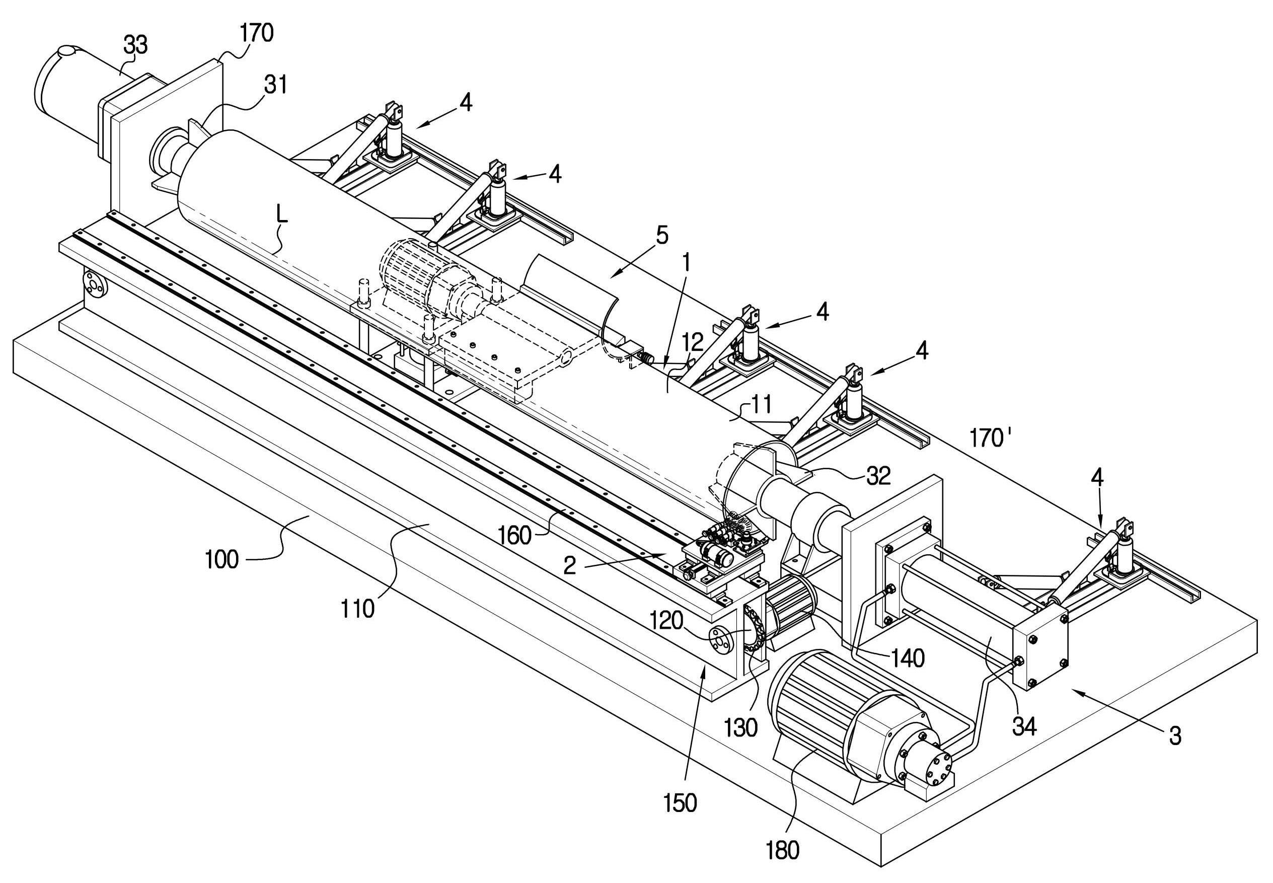
도 1에 도시된 바와 같이 본 발명은 금속재 강관(11) 외주면에 합성수지 재질의 외피(12)가 피복되고 절삭작업에 필요한 길이로 절단된 폐피복관(1)과, 지면에 설치된 작업대(100)와, 이 작업대(100) 상부에 길이방향으로 장착된 지지대(110)와, 이 지지대(110)의 수직벽 양측에 장착되는 한 쌍의 체인기어(120)와 이 체인기어(120)에 맞물려 회전하는 체인(130) 및 상기 체인기어(120)에 회전동력을 전달하는 감속모터(140)로 이루어지는 이동수단(150)과, 상기 지지대(110)의 상부 수평면 길이방향으로 고정된 가이드램(160)에 안착되면서 상기 체인(130)에 고정되어 좌우로 왕복 이동하는 예열 및 탈피수단(2)과, 상기 작업대(100)에 고정된 제1 지지대(170) 및 제2 지지대(170')에 장착되어 상기 폐피복관(1)의 양단을 고정하고 회전시키는 회전수단(3) 및 유체 공급용 유압유니트(180)를 포함하여 이루어지는 절삭 가공장치의 기본 구성을 이용하게 되며, 상기 구성에 대한 작용등의 구체적인 설명은 생략한다.1, the present invention includes a
본 발명의 핵심기술은 대형의 폐피복관(1)을 절삭 가공을 위한 대기 위치로 편리하게 이동시키는 이송수단(4)과, 대기중인 폐피복관(1)을 절삭 가공을 위한 회전수단(3)으로 공급 및 배출하는 리프팅수단(5)과, 폐피복관(1)의 외피를 용이하게 절삭할 수 있도록 예열 및 절삭하는 예열 및 탈피수단(2)을 개량한 것이다. 상기 폐피복관(1)은 수거(운반) 및 탈피가 용이하고 물류비용이 저렴한 500㎜~600㎜ 길이로 절단하는 것이 바람직하며, 절삭 가공을 위한 회전수단(3) 역시 500㎜~600㎜ 길이의 폐피복관(1)을 고정한 후 가공할 수 있도록 이루어진다.The core technology of the present invention comprises a transfer means (4) for conveniently moving a large cladding tube (1) to a standby position for cutting processing, and a rotating cladding tube (1) (5) for supplying and discharging the waste cladding tube (1), and a preheating and removing means (2) for preheating and cutting so that the sheath of the cladding cladding tube (1) can be easily cut. It is preferable that the
즉, 본 발명의 상기 예열 및 탈피수단(2)은 도 1 및 도 2에서와 같이 가이드램(160)에 안착되는 하부베이스(21)와 이 하부베이스(21)의 상부에 고정된 가이드램(160')에 안착되어 전후진하는 상부베이스(22)와, 이 상부베이스(22)의 상단 일측에 장착되면서 절삭용 바이트(231)를 고정한 후 정지 또는 회전하는 고정대(23)와, 상기 상부베이스(22)의 상단 후방에 고정되는 부탄용 가스탱크(24) 및 전방에 장착되면서 가스를 공급받아 연소열로 폐피복관(1)의 외피(12)을 예열시키는 토오치(25)로 이루어진다.1 and 2, the preheating and demolding means 2 of the present invention includes a
상기 예열 및 탈피수단(2)의 토오치(25)는 폐피복관(1)의 절삭라인(L) 길이방향으로 2~3개의 연소노즐(251, 252, 253)이 연이어 형성되고, 이 다수의 연소노즐(251, 252, 253)은 앞쪽의 연소노즐(251)로부터 뒤쪽의 연소노즐(252) 및 연소노즐(253)로 이어가면서 연소 화염의 발열량을 감소시키면서 절삭에 용이한 상태로 화염 열기를 발생하게 되며, 상기 화염 열기 온도는 외피(12)가 연화(용융)가 이루어지는 온도 이하가 적합하며 연소 화염은 100℃~300℃ 범위에서 조정하면서 앞쪽의 연소노즐(251)이 가장 높은 온도이고 뒤쪽의 연소노즐(252) 및 연소노즐(253)은 단계적으로 낮은 가열 온도로 유지시키면서 폐피복관(1)의 회전 속도와 함께 조정하여 온도를 유지시키도록 이루어진다. The
또한, 상기 회전수단(3)은 500㎜~600㎜ 길이로 절단되어 공급되는 크고 작은 직경의 모든 폐피복관(1)의 양단을 고정하는 원추형상의 고정용 척(31) 및 가변형 척(32)과, 상기 고정용 척(31)을 회전시키도록 선단에 결합하면서 제1 지지대(170)에 장착되는 구동모터(33) 및 상기 가변형 척(32)을 회전시키도록 실린더 축 선단에 결합하면서 제2 지지대(170')에 장착되어 폐피복관(1)의 500㎜~600㎜ 길이를 모두 고정할 수 있도록 실린던 축을 전후진하는 유압실리더(34)로 이루어진다.The rotating
또한, 상기 회전수단(3)의 일측 길이방향으로 도 1에서와 같이 폐피복관(1)을 편리하게 유입 및 배출시키도록 다수 배치되는 이송수단(4) 및 상기 폐피복관(1)을 가공위치로 공급 및 복귀시키는 리프트수단(5)이 마련되어 이루어진다.In addition, as shown in Fig. 1, a plurality of
상기 다수의 이송수단(4)은 도 3에서와 같이 단면이 'ㄷ' 또는 'H'자 형강의 강재 받침틀(41)과, 이 받침틀(41)의 양측에 장착되는 유압잭(42)과, 폐피복관(1)을 안착시키면서 회전 및 높낮이가 조정되도록 내측 일단이 받침틀(41)에 힌지 결합되고 외측 일단이 유압잭(42)에 힌지 결합되어 'V'자 형상을 이루는 한 쌍의 롤러(43, 43')로 이루어진다. 그리고 상기 한 쌍의 롤러(43, 43')는 도 4에서와 같이 폐피복관(1) 직경이 크고 작을 때 유압잭(24)을 작동시켜 한 쌍의 롤러(43, 43')의 외측을 올리거나 낮추어 폐피복관(1)을 안전하게 안착시킨 후 이동할 수 있도록 높낮이를 조절할 수 있도록 이루어진다.As shown in FIG. 3, the plurality of conveying means 4 includes a
상기 리프트수단(5)은 도 1 및 도 5에서와 같이 작업대(100)에 고정되는 하부판(51)과, 이 하부판(51)의 중앙에 장착되는 유압실린더(52)와, 상기 하부판(51) 사방에 직립상태로 고정되는 기둥(53)과, 상기 기둥(53)에 사방이 끼워지고 중앙이 상기 유압실린더(52)의 작동축에 고정되어 상하이동하는 상부판(54)과, 상기 상부판(54) 상부에 안착된 후 고정되는 구동모터(55)와, 상기 구동모터(55)의 회전축에 중앙부분이 고정되면서 일측에는 폐피복관(1)의 무게 중심부분을 안착시키는 버킷부(561)가 타측에는 균형추(562)를 고정시킨 회전리프트부(56)가 마련되어 이루어진다.The lift means 5 includes a
그리고 도 5 및 도 6에서와 같이 상기 리프트수단(5)의 버킷부(561) 하측 선단에는 지지편(57)이 형성되고, 이 지지편(57)에 축설되면서 스프링(58)에 의해 지지되면서 외부로 노출되는 파지부분(591)과 내측의 걸림부분(592)으로 이루어지는 걸림핀(59) 및 이 걸림핀(59)에 의해 정지 또는 회전되도록 지지편(57)에 축설되면서 버킷부(561)에 유입된 폐피복관(1)이 이탈됨을 방지하는 버팀목(50)이 마련되어 이루어진다.5 and 6, a
상기와 같이 구성된 본 발명은 500㎜~600㎜ 길이로 절단되어 공급되는 크고 작은 직경의 폐피복관(1)을 도 1 및 도 4에서와 같이 그 직경에 적합하도록 이송수단(4)의 유압잭(42)을 이용하여 롤러(43, 43')의 높낮이를 조정하면 폐피복관(1)은 안정적으로 이동할 수 있는 조건을 제공하게 되고, 길이 방향으로 배치된 다수의 이동수단(4)의 롤러(43, 43')에 순차적으로 폐피복관(1)이 안착되면서 편리하게 이동된 후 가공 준비상태로 대기시키게 된다.The present invention having the above-described structure is characterized in that a large and small
상기 폐피복관(1)의 대기상태는 도 6에서와 같이 리프트수단(5)의 버킷부(561)에 폐피복관(1)의 무게 중심부분이 위치된다.As shown in Fig. 6, the center of gravity of the
이어서, 리프트수단(5)의 버팀목(50)을 회전시켜 폐피복관(1)의 외피(12)부분에 접하면 폐피복관(1)이 버킷부(561) 외부로 이탈됨을 방지하게 되고, 상기 버팀목(50) 역시 스피링(58)에 지지되는 걸림핀(59)의 걸림부분(592)에 의해 전지 상태를 유지하게 된다.When the
상기 상태에서 구동모터(55)의 작동으로 회전리브트부(56)을 회전시켜 버킷부(56)를 도 6에서와 같이 시계반대방향으로 회전하여 직립상태가 되면 도 1에서와 같이 가공을 하는 회전수단(3)의 고정용 척(31) 및 가변형 척(32)에 고정될 수 있는 위치에 도달된다.When the
이어서, 갈림핀(59)의 파지부분을 외측으로 당겨 걸림부분(592)을 버팀목(50)으로 이탈시키면 버팀목(50)을 도 6에서와 같이 시계방향으로 회전하여 폐피복관(1)의 접촉을 방지시키고, 회전수단(3)의 유압실린더(34)를 작동시켜 가변형 척(32)이 폐피복관(1)의 일단으로 유입되면 폐피복관(1)의 타단은 고정용 척(31)에 유입되면서 견고하게 폐피복관(1)를 고정하게 된다.Then, when the
이어서, 도 7에서와 같이 폐피복관(1)의 회전에 방해를 받지 못하도록 리프트수단(5)의 유압실린더(52)를 작동시켜 상부판(54)을 하강시키면 버킷부(561)이 이격(T2)시킨 후 구동모터(33)을 통해 폐피복관(1)을 회전시키게 되고, 폐피복관(1)의 외피(12)를 탈피하기 위해 예열 및 탈피수단(2)의 토오치(25)의 연소노즐(251, 252, 253)로부터 화염을 발생시켜 외피(12)를 연화(용융)되기 전까지 예열하게 되며, 이때 앞쪽의 연소노즐(251)이 가장 높은 온도이고 뒤쪽의 연소노즐(252) 및 연소노즐(253)은 단계적으로 낮은 가열 온도로 유지시키면서 폐피복관(1)의 회전 속도를 함께 조정하여 절삭이 용이한 온도를 유지시키게 된다.7, when the
상기 폐피복관(1)의 외피(12)가 예열되면 이어서 이동수단(150)의 감속모터(130)의 작동으로 체인기어(120)를 회전시키면 체인(130)이 이동하면서 예열 및 탈피수단(2)을 절삭라인(L)으로 도 2에서와 같이 이동하여 바이트(231)로 외피(12)를 용이하게 절삭하게 되고, 절삭되는 외피(12)는 미도시된 통상적인 수집장치를 통해 수집하게 된다.When the
상기 폐피복관(1)의 외피(12) 절삭 가공이 완료되면 역순으로 리프트수단(5) 및 이송수단(4)를 이용하여 외부로 배출하여 강관(11)을 재활용하게 된다.When the cutting process of the
따라서, 본 발명은 폐피복관(1)의 이송 및 가공 위치로 공급 그리고 예열과 절삭을 통해 용이하게 외피(12)를 절삭한 후 강관(11)을 재활용하는 일련의 공정이 안정적이고 편리하며 동시에 자원의 재활용 효과를 대폭적으로 증대시킬 수 있어 경제적인 것이다.Accordingly, the present invention provides a stable and convenient process for recycling the
이상에서 본 발명의 바람직한 실시 예와 관련하여 설명하고 도시하였지만, 상기 도시되고 설명된 그대로의 구성 및 작용에 한정하는 것은 아니다. 따라서 상기 실시 예를 적절히 변형 및 수정 가능함을 당업자들은 잘 이해할 수 있으므로 적절한 변경 및 수정과 균등물들은 본 발명의 범위에 속하는 것으로 간주하여야 할 것이다.While the present invention has been particularly shown and described with reference to exemplary embodiments thereof, it is to be understood that the invention is not limited to the disclosed exemplary embodiments. Accordingly, those skilled in the art will appreciate that various modifications, additions and substitutions are possible, without departing from the scope and spirit of the invention as disclosed in the accompanying claims.
1: 폐피복관 11: 강관
12: 외피 2: 예열 및 탈피수단
21: 하부베이스 22: 상부케이스
23: 고정대 24: 가스탱크
25: 토오치 3: 회전수단
31: 고정용 척 32: 회전용 척
33: 구동모터 34: 유압실린더
4: 이송수단 41: 받침틀
42: 유압잭 43, 43': 롤러
5: 리프트수단 51: 하부판
52: 유압실린더 53: 기둥
54: 상부판 55: 구동모터
56: 회전리프트부 57: 지지편
58: 스프링 59: 걸림핀
50: 버팀목 561: 버킷부
562: 균형추 100: 작업대
110: 지지대 120: 체인기어
130: 체인 140: 감속모터
150: 이동수단 160: 가이드램
170: 제1 지지대 171': 제2 지지대
180: 유압유니트1: Closed closure pipe 11: Steel pipe
12: envelope 2: preheating and peeling means
21: lower base 22: upper case
23: fixing table 24: gas tank
25: soil 3: rotation means
31: Fixing Chuck 32: Rotating Chuck
33: drive motor 34: hydraulic cylinder
4: Feeding means 41: Supporting frame
42:
5: Lift means 51:
52: Hydraulic cylinder 53: Column
54: top plate 55: drive motor
56: rotating lift part 57: supporting piece
58: spring 59: engaging pin
50: strut 561: bucket
562: Balance 100: Workbench
110: support 120: chain gear
130: chain 140: deceleration motor
150: moving means 160: guide ram
170: first support 171 ': second support
180: Hydraulic unit
Claims (5)
상기 예열 및 탈피수단(2)은 가이드램(160)에 안착되는 하부베이스(21)와 이 하부베이스(21)의 상부에 고정된 가이드램(160')에 안착되어 전후진하는 상부베이스(22)와, 이 상부베이스(22)의 상단 일측에 장착되면서 절삭용 바이트(231)를 고정한 후 정지 또는 회전하는 고정대(23)와, 상기 상부베이스(22)의 상단 후방에 고정되는 가스탱크(24) 및 전방에 장착되면서 가스를 공급받아 연소열로 폐피복관(1)의 외피(12)을 예열시키는 토오치(25)로 이루어지며;
상기 회전수단(3)은 폐피복관(1)의 양단을 고정하는 원추형상의 고정용 척(31) 및 가변형 척(32)과, 상기 고정용 척(31)을 회전시키도록 선단에 결합하면서 제1 지지대(170)에 장착되는 구동모터(33) 및 상기 가변형 척(32)을 회전시키도록 선단에 결합하면서 제2 지지대(170')에 장착되는 유압실리더(34)로 이루어지고;
상기 회전수단(3)의 일측 길이방향으로 폐피복관(1)을 유입 및 배출시키도록 다수 배치되는 이송수단(4) 및 상기 폐피복관(1)을 가공위치로 공급 및 복귀시키는 리프트수단(5)이 마련되어 이루어진 것을 특징으로 하는 폐피복관 탈피장치.
A waste cladding tube 1 covered with a synthetic resin sheath 12 on the outer circumferential surface of the metal steel pipe 11 and cut to a length necessary for cutting operation; a work table 100 installed on the ground; A pair of chain gears 120 mounted on both sides of the vertical wall of the support frame 110, a chain 130 rotating in engagement with the chain gear 120, And a deceleration motor 140 for transmitting rotation power to the chain 130. The guide 150 is fixed to the chain 130 while being mounted on a guide ram 160 fixed in the longitudinal direction of the upper surface of the support 110, And a first support 170 and a second support 170 'fixed to the work table 100 to fix both ends of the waste cladding 1 to each other, (3) for rotating the fluid supply unit (180) and a fluid supply hydraulic unit (180);
The preheating and demolding means 2 includes a lower base 21 which is seated in a guide ram 160 and an upper base 22 which is seated on a guide ram 160 'fixed to the upper portion of the lower base 21, A fixing table 23 mounted on one side of the upper end of the upper base 22 for stopping or rotating after fixing the cutting bite 231 and a gas tank 24 fixed to the upper rear of the upper base 22 And a tundish 25 which is mounted on the front side to supply gas and preheat the shell 12 of the cladding tube 1 with combustion heat;
The rotating means 3 includes a conical fixing chuck 31 and a variable chuck 32 for fixing both ends of the cladding closure 1, A drive motor 33 mounted on the support table 170 and a hydraulic cylinder 34 mounted on the second support table 170 'while being coupled to the tip to rotate the variable chuck 32;
A plurality of conveying means 4 arranged to feed and discharge the waste cladding tube 1 in the longitudinal direction of the rotating means 3 and a lift means 5 for feeding and returning the waste cladding tube 1 to the working position, Wherein the first and second closure members are made of a metal.
The apparatus according to claim 1, wherein the plurality of conveying means (4) comprises a steel support frame (41) having a "c" or "H" shaped cross section, a hydraulic jack (42) mounted on both sides of the support frame (41) A pair of rollers 43 and 43 are hinged to the support frame 41 at one end and hinged at the other end to the hydraulic jack 42 so as to adjust the rotation and the height while seating the closure cap 1, 43 '). ≪ / RTI >
The lift device according to claim 1, wherein the lift means includes a lower plate fixed to the work platform, a hydraulic cylinder mounted at the center of the lower plate, An upper plate 54 which is vertically movable and which is fixed to the operating shaft of the hydraulic cylinder 52 with its center being fixed to the column 53 at the center; And a bucket part 561 for seating the center of gravity of the cladding closure pipe 1 at one side while the central part is fixed to the rotation shaft of the driving motor 55. [ Is provided with a rotary lift portion (56) to which a balance weight (562) is fixed.
The method according to claim 1, wherein the soil 25 of the preheating and removing means 2 is formed by two to three combustion nozzles 251, 252, 523 formed in the longitudinal direction of the cladding closure 1 Apparatus for removing closure of lung closure.
Priority Applications (1)
| Application Number | Priority Date | Filing Date | Title |
|---|---|---|---|
| KR1020170057212A KR101945616B1 (en) | 2017-05-08 | 2017-05-08 | Waste covering pipe stripping apparatus |
Applications Claiming Priority (1)
| Application Number | Priority Date | Filing Date | Title |
|---|---|---|---|
| KR1020170057212A KR101945616B1 (en) | 2017-05-08 | 2017-05-08 | Waste covering pipe stripping apparatus |
Publications (2)
| Publication Number | Publication Date |
|---|---|
| KR20180123249A KR20180123249A (en) | 2018-11-16 |
| KR101945616B1 true KR101945616B1 (en) | 2019-02-08 |
Family
ID=64565131
Family Applications (1)
| Application Number | Title | Priority Date | Filing Date |
|---|---|---|---|
| KR1020170057212A KR101945616B1 (en) | 2017-05-08 | 2017-05-08 | Waste covering pipe stripping apparatus |
Country Status (1)
| Country | Link |
|---|---|
| KR (1) | KR101945616B1 (en) |
Families Citing this family (1)
| Publication number | Priority date | Publication date | Assignee | Title |
|---|---|---|---|---|
| CN114670260B (en) * | 2022-03-29 | 2024-04-12 | 绍兴英格利新材料有限公司 | Energy-saving extraction device for extracting waste nickel |
Citations (2)
| Publication number | Priority date | Publication date | Assignee | Title |
|---|---|---|---|---|
| KR101012022B1 (en) | 2008-12-26 | 2011-01-31 | 서광기연 주식회사 | End facing machine for pipe |
| KR101191773B1 (en) | 2012-05-25 | 2012-10-16 | (주)에이엘베스트 | Molting apparatus for pipe |
-
2017
- 2017-05-08 KR KR1020170057212A patent/KR101945616B1/en active IP Right Grant
Patent Citations (2)
| Publication number | Priority date | Publication date | Assignee | Title |
|---|---|---|---|---|
| KR101012022B1 (en) | 2008-12-26 | 2011-01-31 | 서광기연 주식회사 | End facing machine for pipe |
| KR101191773B1 (en) | 2012-05-25 | 2012-10-16 | (주)에이엘베스트 | Molting apparatus for pipe |
Also Published As
| Publication number | Publication date |
|---|---|
| KR20180123249A (en) | 2018-11-16 |
Similar Documents
| Publication | Publication Date | Title |
|---|---|---|
| CN105127501A (en) | Automatic rotary cutting device for thin-wall pipe fittings and rotary cutting method with automatic rotary cutting device | |
| CN104492988A (en) | Reamer | |
| CN111360091B (en) | Efficient cold-drawing equipment for stainless steel seamless steel pipe and machining method thereof | |
| CN103331387A (en) | Feeding device of pipe fitting machining device | |
| CN106670660A (en) | Circular tube intersecting line cutting production line | |
| CN110202428B (en) | Paper tube deformation repairing machine | |
| CN112275855A (en) | Elbow integration equipment that can buckle fast | |
| KR101945616B1 (en) | Waste covering pipe stripping apparatus | |
| CN112045283A (en) | Efficient full-automatic welding device for pipeline | |
| KR20160131817A (en) | Drums safety cutting device | |
| CN108000157A (en) | Injection tube processes assembly | |
| KR101284224B1 (en) | Pipe chamfering machine | |
| CN108856892B (en) | Automatic handle automatic feeding and chamfering equipment | |
| CN105563248A (en) | Automatic feeding device for centerless grinding of candan universal joint shaft sleeves | |
| CN213827481U (en) | Direct-feeding type semi-automatic feeding mechanical device | |
| CN215393105U (en) | Automatic fusion welding device for production of PTA process punch | |
| CN210233228U (en) | Stripping device for outer cladding of half-clad sucker rod | |
| CN211305152U (en) | Surfacing machine for automatically repairing roller | |
| CN212470335U (en) | Metal welding auxiliary machine tool with clamping device | |
| CN213496855U (en) | Long service life's material cutting machine | |
| CN113492252B (en) | Automatic fusion welding device for PTA process punch production | |
| CN113909430B (en) | Production method of novel large-specification full-automatic high-strength mining compact chain production line | |
| CN212823158U (en) | Self-centering machining equipment for milling teeth of door closer piston | |
| CN215093939U (en) | Cutting platform is used in FRP pipe way production | |
| CN204320999U (en) | A kind of staving press |
Legal Events
| Date | Code | Title | Description |
|---|---|---|---|
| A201 | Request for examination | ||
| E902 | Notification of reason for refusal | ||
| E701 | Decision to grant or registration of patent right | ||
| GRNT | Written decision to grant |