KR101895307B1 - Abatement and strip process chamber in a dual loadrock configuration - Google Patents
Abatement and strip process chamber in a dual loadrock configuration Download PDFInfo
- Publication number
- KR101895307B1 KR101895307B1 KR1020137025383A KR20137025383A KR101895307B1 KR 101895307 B1 KR101895307 B1 KR 101895307B1 KR 1020137025383 A KR1020137025383 A KR 1020137025383A KR 20137025383 A KR20137025383 A KR 20137025383A KR 101895307 B1 KR101895307 B1 KR 101895307B1
- Authority
- KR
- South Korea
- Prior art keywords
- chamber
- substrate
- chamber volume
- load lock
- support assembly
- Prior art date
Links
Images


Classifications
-
- H—ELECTRICITY
- H01—ELECTRIC ELEMENTS
- H01L—SEMICONDUCTOR DEVICES NOT COVERED BY CLASS H10
- H01L21/00—Processes or apparatus adapted for the manufacture or treatment of semiconductor or solid state devices or of parts thereof
- H01L21/02—Manufacture or treatment of semiconductor devices or of parts thereof
- H01L21/04—Manufacture or treatment of semiconductor devices or of parts thereof the devices having at least one potential-jump barrier or surface barrier, e.g. PN junction, depletion layer or carrier concentration layer
- H01L21/18—Manufacture or treatment of semiconductor devices or of parts thereof the devices having at least one potential-jump barrier or surface barrier, e.g. PN junction, depletion layer or carrier concentration layer the devices having semiconductor bodies comprising elements of Group IV of the Periodic System or AIIIBV compounds with or without impurities, e.g. doping materials
- H01L21/30—Treatment of semiconductor bodies using processes or apparatus not provided for in groups H01L21/20 - H01L21/26
- H01L21/302—Treatment of semiconductor bodies using processes or apparatus not provided for in groups H01L21/20 - H01L21/26 to change their surface-physical characteristics or shape, e.g. etching, polishing, cutting
- H01L21/306—Chemical or electrical treatment, e.g. electrolytic etching
- H01L21/3065—Plasma etching; Reactive-ion etching
-
- H—ELECTRICITY
- H01—ELECTRIC ELEMENTS
- H01J—ELECTRIC DISCHARGE TUBES OR DISCHARGE LAMPS
- H01J37/00—Discharge tubes with provision for introducing objects or material to be exposed to the discharge, e.g. for the purpose of examination or processing thereof
- H01J37/32—Gas-filled discharge tubes
- H01J37/32431—Constructional details of the reactor
- H01J37/32798—Further details of plasma apparatus not provided for in groups H01J37/3244 - H01J37/32788; special provisions for cleaning or maintenance of the apparatus
- H01J37/32816—Pressure
- H01J37/32834—Exhausting
- H01J37/32844—Treating effluent gases
-
- H—ELECTRICITY
- H01—ELECTRIC ELEMENTS
- H01L—SEMICONDUCTOR DEVICES NOT COVERED BY CLASS H10
- H01L21/00—Processes or apparatus adapted for the manufacture or treatment of semiconductor or solid state devices or of parts thereof
- H01L21/02—Manufacture or treatment of semiconductor devices or of parts thereof
- H01L21/02041—Cleaning
- H01L21/02057—Cleaning during device manufacture
- H01L21/02068—Cleaning during device manufacture during, before or after processing of conductive layers, e.g. polysilicon or amorphous silicon layers
- H01L21/02071—Cleaning during device manufacture during, before or after processing of conductive layers, e.g. polysilicon or amorphous silicon layers the processing being a delineation, e.g. RIE, of conductive layers
-
- H—ELECTRICITY
- H01—ELECTRIC ELEMENTS
- H01L—SEMICONDUCTOR DEVICES NOT COVERED BY CLASS H10
- H01L21/00—Processes or apparatus adapted for the manufacture or treatment of semiconductor or solid state devices or of parts thereof
- H01L21/02—Manufacture or treatment of semiconductor devices or of parts thereof
- H01L21/04—Manufacture or treatment of semiconductor devices or of parts thereof the devices having at least one potential-jump barrier or surface barrier, e.g. PN junction, depletion layer or carrier concentration layer
- H01L21/18—Manufacture or treatment of semiconductor devices or of parts thereof the devices having at least one potential-jump barrier or surface barrier, e.g. PN junction, depletion layer or carrier concentration layer the devices having semiconductor bodies comprising elements of Group IV of the Periodic System or AIIIBV compounds with or without impurities, e.g. doping materials
- H01L21/30—Treatment of semiconductor bodies using processes or apparatus not provided for in groups H01L21/20 - H01L21/26
- H01L21/31—Treatment of semiconductor bodies using processes or apparatus not provided for in groups H01L21/20 - H01L21/26 to form insulating layers thereon, e.g. for masking or by using photolithographic techniques; After treatment of these layers; Selection of materials for these layers
- H01L21/3205—Deposition of non-insulating-, e.g. conductive- or resistive-, layers on insulating layers; After-treatment of these layers
- H01L21/321—After treatment
- H01L21/3213—Physical or chemical etching of the layers, e.g. to produce a patterned layer from a pre-deposited extensive layer
- H01L21/32133—Physical or chemical etching of the layers, e.g. to produce a patterned layer from a pre-deposited extensive layer by chemical means only
- H01L21/32135—Physical or chemical etching of the layers, e.g. to produce a patterned layer from a pre-deposited extensive layer by chemical means only by vapour etching only
- H01L21/32136—Physical or chemical etching of the layers, e.g. to produce a patterned layer from a pre-deposited extensive layer by chemical means only by vapour etching only using plasmas
- H01L21/32137—Physical or chemical etching of the layers, e.g. to produce a patterned layer from a pre-deposited extensive layer by chemical means only by vapour etching only using plasmas of silicon-containing layers
-
- H—ELECTRICITY
- H01—ELECTRIC ELEMENTS
- H01L—SEMICONDUCTOR DEVICES NOT COVERED BY CLASS H10
- H01L21/00—Processes or apparatus adapted for the manufacture or treatment of semiconductor or solid state devices or of parts thereof
- H01L21/02—Manufacture or treatment of semiconductor devices or of parts thereof
- H01L21/04—Manufacture or treatment of semiconductor devices or of parts thereof the devices having at least one potential-jump barrier or surface barrier, e.g. PN junction, depletion layer or carrier concentration layer
- H01L21/18—Manufacture or treatment of semiconductor devices or of parts thereof the devices having at least one potential-jump barrier or surface barrier, e.g. PN junction, depletion layer or carrier concentration layer the devices having semiconductor bodies comprising elements of Group IV of the Periodic System or AIIIBV compounds with or without impurities, e.g. doping materials
- H01L21/30—Treatment of semiconductor bodies using processes or apparatus not provided for in groups H01L21/20 - H01L21/26
- H01L21/31—Treatment of semiconductor bodies using processes or apparatus not provided for in groups H01L21/20 - H01L21/26 to form insulating layers thereon, e.g. for masking or by using photolithographic techniques; After treatment of these layers; Selection of materials for these layers
- H01L21/3205—Deposition of non-insulating-, e.g. conductive- or resistive-, layers on insulating layers; After-treatment of these layers
- H01L21/321—After treatment
- H01L21/3213—Physical or chemical etching of the layers, e.g. to produce a patterned layer from a pre-deposited extensive layer
- H01L21/32133—Physical or chemical etching of the layers, e.g. to produce a patterned layer from a pre-deposited extensive layer by chemical means only
- H01L21/32135—Physical or chemical etching of the layers, e.g. to produce a patterned layer from a pre-deposited extensive layer by chemical means only by vapour etching only
- H01L21/32138—Physical or chemical etching of the layers, e.g. to produce a patterned layer from a pre-deposited extensive layer by chemical means only by vapour etching only pre- or post-treatments, e.g. anti-corrosion processes
-
- H—ELECTRICITY
- H01—ELECTRIC ELEMENTS
- H01L—SEMICONDUCTOR DEVICES NOT COVERED BY CLASS H10
- H01L21/00—Processes or apparatus adapted for the manufacture or treatment of semiconductor or solid state devices or of parts thereof
- H01L21/67—Apparatus specially adapted for handling semiconductor or electric solid state devices during manufacture or treatment thereof; Apparatus specially adapted for handling wafers during manufacture or treatment of semiconductor or electric solid state devices or components ; Apparatus not specifically provided for elsewhere
- H01L21/67005—Apparatus not specifically provided for elsewhere
- H01L21/67011—Apparatus for manufacture or treatment
- H01L21/67017—Apparatus for fluid treatment
- H01L21/67063—Apparatus for fluid treatment for etching
- H01L21/67069—Apparatus for fluid treatment for etching for drying etching
-
- H—ELECTRICITY
- H01—ELECTRIC ELEMENTS
- H01L—SEMICONDUCTOR DEVICES NOT COVERED BY CLASS H10
- H01L21/00—Processes or apparatus adapted for the manufacture or treatment of semiconductor or solid state devices or of parts thereof
- H01L21/67—Apparatus specially adapted for handling semiconductor or electric solid state devices during manufacture or treatment thereof; Apparatus specially adapted for handling wafers during manufacture or treatment of semiconductor or electric solid state devices or components ; Apparatus not specifically provided for elsewhere
- H01L21/67005—Apparatus not specifically provided for elsewhere
- H01L21/67011—Apparatus for manufacture or treatment
- H01L21/67098—Apparatus for thermal treatment
- H01L21/67103—Apparatus for thermal treatment mainly by conduction
-
- H—ELECTRICITY
- H01—ELECTRIC ELEMENTS
- H01L—SEMICONDUCTOR DEVICES NOT COVERED BY CLASS H10
- H01L21/00—Processes or apparatus adapted for the manufacture or treatment of semiconductor or solid state devices or of parts thereof
- H01L21/67—Apparatus specially adapted for handling semiconductor or electric solid state devices during manufacture or treatment thereof; Apparatus specially adapted for handling wafers during manufacture or treatment of semiconductor or electric solid state devices or components ; Apparatus not specifically provided for elsewhere
- H01L21/67005—Apparatus not specifically provided for elsewhere
- H01L21/67011—Apparatus for manufacture or treatment
- H01L21/67155—Apparatus for manufacturing or treating in a plurality of work-stations
- H01L21/67201—Apparatus for manufacturing or treating in a plurality of work-stations characterized by the construction of the load-lock chamber
-
- H—ELECTRICITY
- H01—ELECTRIC ELEMENTS
- H01L—SEMICONDUCTOR DEVICES NOT COVERED BY CLASS H10
- H01L21/00—Processes or apparatus adapted for the manufacture or treatment of semiconductor or solid state devices or of parts thereof
- H01L21/67—Apparatus specially adapted for handling semiconductor or electric solid state devices during manufacture or treatment thereof; Apparatus specially adapted for handling wafers during manufacture or treatment of semiconductor or electric solid state devices or components ; Apparatus not specifically provided for elsewhere
- H01L21/677—Apparatus specially adapted for handling semiconductor or electric solid state devices during manufacture or treatment thereof; Apparatus specially adapted for handling wafers during manufacture or treatment of semiconductor or electric solid state devices or components ; Apparatus not specifically provided for elsewhere for conveying, e.g. between different workstations
- H01L21/67703—Apparatus specially adapted for handling semiconductor or electric solid state devices during manufacture or treatment thereof; Apparatus specially adapted for handling wafers during manufacture or treatment of semiconductor or electric solid state devices or components ; Apparatus not specifically provided for elsewhere for conveying, e.g. between different workstations between different workstations
-
- H—ELECTRICITY
- H01—ELECTRIC ELEMENTS
- H01L—SEMICONDUCTOR DEVICES NOT COVERED BY CLASS H10
- H01L21/00—Processes or apparatus adapted for the manufacture or treatment of semiconductor or solid state devices or of parts thereof
- H01L21/67—Apparatus specially adapted for handling semiconductor or electric solid state devices during manufacture or treatment thereof; Apparatus specially adapted for handling wafers during manufacture or treatment of semiconductor or electric solid state devices or components ; Apparatus not specifically provided for elsewhere
- H01L21/677—Apparatus specially adapted for handling semiconductor or electric solid state devices during manufacture or treatment thereof; Apparatus specially adapted for handling wafers during manufacture or treatment of semiconductor or electric solid state devices or components ; Apparatus not specifically provided for elsewhere for conveying, e.g. between different workstations
- H01L21/67739—Apparatus specially adapted for handling semiconductor or electric solid state devices during manufacture or treatment thereof; Apparatus specially adapted for handling wafers during manufacture or treatment of semiconductor or electric solid state devices or components ; Apparatus not specifically provided for elsewhere for conveying, e.g. between different workstations into and out of processing chamber
- H01L21/67742—Mechanical parts of transfer devices
-
- H—ELECTRICITY
- H01—ELECTRIC ELEMENTS
- H01L—SEMICONDUCTOR DEVICES NOT COVERED BY CLASS H10
- H01L21/00—Processes or apparatus adapted for the manufacture or treatment of semiconductor or solid state devices or of parts thereof
- H01L21/67—Apparatus specially adapted for handling semiconductor or electric solid state devices during manufacture or treatment thereof; Apparatus specially adapted for handling wafers during manufacture or treatment of semiconductor or electric solid state devices or components ; Apparatus not specifically provided for elsewhere
- H01L21/683—Apparatus specially adapted for handling semiconductor or electric solid state devices during manufacture or treatment thereof; Apparatus specially adapted for handling wafers during manufacture or treatment of semiconductor or electric solid state devices or components ; Apparatus not specifically provided for elsewhere for supporting or gripping
- H01L21/6831—Apparatus specially adapted for handling semiconductor or electric solid state devices during manufacture or treatment thereof; Apparatus specially adapted for handling wafers during manufacture or treatment of semiconductor or electric solid state devices or components ; Apparatus not specifically provided for elsewhere for supporting or gripping using electrostatic chucks
-
- H—ELECTRICITY
- H01—ELECTRIC ELEMENTS
- H01L—SEMICONDUCTOR DEVICES NOT COVERED BY CLASS H10
- H01L21/00—Processes or apparatus adapted for the manufacture or treatment of semiconductor or solid state devices or of parts thereof
- H01L21/67—Apparatus specially adapted for handling semiconductor or electric solid state devices during manufacture or treatment thereof; Apparatus specially adapted for handling wafers during manufacture or treatment of semiconductor or electric solid state devices or components ; Apparatus not specifically provided for elsewhere
- H01L21/683—Apparatus specially adapted for handling semiconductor or electric solid state devices during manufacture or treatment thereof; Apparatus specially adapted for handling wafers during manufacture or treatment of semiconductor or electric solid state devices or components ; Apparatus not specifically provided for elsewhere for supporting or gripping
- H01L21/687—Apparatus specially adapted for handling semiconductor or electric solid state devices during manufacture or treatment thereof; Apparatus specially adapted for handling wafers during manufacture or treatment of semiconductor or electric solid state devices or components ; Apparatus not specifically provided for elsewhere for supporting or gripping using mechanical means, e.g. chucks, clamps or pinches
- H01L21/68714—Apparatus specially adapted for handling semiconductor or electric solid state devices during manufacture or treatment thereof; Apparatus specially adapted for handling wafers during manufacture or treatment of semiconductor or electric solid state devices or components ; Apparatus not specifically provided for elsewhere for supporting or gripping using mechanical means, e.g. chucks, clamps or pinches the wafers being placed on a susceptor, stage or support
- H01L21/68742—Apparatus specially adapted for handling semiconductor or electric solid state devices during manufacture or treatment thereof; Apparatus specially adapted for handling wafers during manufacture or treatment of semiconductor or electric solid state devices or components ; Apparatus not specifically provided for elsewhere for supporting or gripping using mechanical means, e.g. chucks, clamps or pinches the wafers being placed on a susceptor, stage or support characterised by a lifting arrangement, e.g. lift pins
-
- H—ELECTRICITY
- H01—ELECTRIC ELEMENTS
- H01L—SEMICONDUCTOR DEVICES NOT COVERED BY CLASS H10
- H01L21/00—Processes or apparatus adapted for the manufacture or treatment of semiconductor or solid state devices or of parts thereof
- H01L21/67—Apparatus specially adapted for handling semiconductor or electric solid state devices during manufacture or treatment thereof; Apparatus specially adapted for handling wafers during manufacture or treatment of semiconductor or electric solid state devices or components ; Apparatus not specifically provided for elsewhere
- H01L21/683—Apparatus specially adapted for handling semiconductor or electric solid state devices during manufacture or treatment thereof; Apparatus specially adapted for handling wafers during manufacture or treatment of semiconductor or electric solid state devices or components ; Apparatus not specifically provided for elsewhere for supporting or gripping
- H01L21/687—Apparatus specially adapted for handling semiconductor or electric solid state devices during manufacture or treatment thereof; Apparatus specially adapted for handling wafers during manufacture or treatment of semiconductor or electric solid state devices or components ; Apparatus not specifically provided for elsewhere for supporting or gripping using mechanical means, e.g. chucks, clamps or pinches
- H01L21/68714—Apparatus specially adapted for handling semiconductor or electric solid state devices during manufacture or treatment thereof; Apparatus specially adapted for handling wafers during manufacture or treatment of semiconductor or electric solid state devices or components ; Apparatus not specifically provided for elsewhere for supporting or gripping using mechanical means, e.g. chucks, clamps or pinches the wafers being placed on a susceptor, stage or support
- H01L21/68785—Apparatus specially adapted for handling semiconductor or electric solid state devices during manufacture or treatment thereof; Apparatus specially adapted for handling wafers during manufacture or treatment of semiconductor or electric solid state devices or components ; Apparatus not specifically provided for elsewhere for supporting or gripping using mechanical means, e.g. chucks, clamps or pinches the wafers being placed on a susceptor, stage or support characterised by the mechanical construction of the susceptor, stage or support
-
- Y—GENERAL TAGGING OF NEW TECHNOLOGICAL DEVELOPMENTS; GENERAL TAGGING OF CROSS-SECTIONAL TECHNOLOGIES SPANNING OVER SEVERAL SECTIONS OF THE IPC; TECHNICAL SUBJECTS COVERED BY FORMER USPC CROSS-REFERENCE ART COLLECTIONS [XRACs] AND DIGESTS
- Y02—TECHNOLOGIES OR APPLICATIONS FOR MITIGATION OR ADAPTATION AGAINST CLIMATE CHANGE
- Y02C—CAPTURE, STORAGE, SEQUESTRATION OR DISPOSAL OF GREENHOUSE GASES [GHG]
- Y02C20/00—Capture or disposal of greenhouse gases
- Y02C20/30—Capture or disposal of greenhouse gases of perfluorocarbons [PFC], hydrofluorocarbons [HFC] or sulfur hexafluoride [SF6]
-
- Y—GENERAL TAGGING OF NEW TECHNOLOGICAL DEVELOPMENTS; GENERAL TAGGING OF CROSS-SECTIONAL TECHNOLOGIES SPANNING OVER SEVERAL SECTIONS OF THE IPC; TECHNICAL SUBJECTS COVERED BY FORMER USPC CROSS-REFERENCE ART COLLECTIONS [XRACs] AND DIGESTS
- Y02—TECHNOLOGIES OR APPLICATIONS FOR MITIGATION OR ADAPTATION AGAINST CLIMATE CHANGE
- Y02P—CLIMATE CHANGE MITIGATION TECHNOLOGIES IN THE PRODUCTION OR PROCESSING OF GOODS
- Y02P70/00—Climate change mitigation technologies in the production process for final industrial or consumer products
- Y02P70/50—Manufacturing or production processes characterised by the final manufactured product
Abstract
본 발명의 실시예들은 기판을 프로세싱할 수 있는 듀얼 로드락 챔버를 제공한다. 하나의 실시예에서는, 듀얼 로드락 챔버가 서로 격리된 제 1 챔버 용적 및 제 2 챔버 용적을 정의하는 챔버 본체를 포함한다. 하부 및 제 2 챔버 용적들의 각각은 기판 이송을 위하여 구성된 2개의 개구부들을 통해 2개의 프로세싱 환경들에 선택적으로 연결가능하다. 또한, 듀얼 로드락 챔버는 제 2 챔버 용적 내에 배치된 피가열 기판 지지 어셈블리를 포함한다. 피가열 기판 지지 어셈블리는 그 위의 기판을 지지 및 가열하도록 구성된다. 또한, 듀얼 로드락 챔버는 플라즈마를 제 2 챔버 용적에 공급하기 위해 제 2 챔버 용적에 연결된 원격지 플라즈마 소스를 포함한다.Embodiments of the present invention provide a dual load lock chamber that is capable of processing substrates. In one embodiment, the dual load lock chamber includes a chamber body defining a first chamber volume and a second chamber volume isolated from each other. Each of the lower and second chamber volumes is selectively connectable to two processing environments through two openings configured for substrate transfer. The dual load lock chamber also includes a heated substrate support assembly disposed within the second chamber volume. The heated substrate support assembly is configured to support and heat the substrate thereon. The dual load lock chamber also includes a remote plasma source coupled to the second chamber volume for supplying a plasma to the second chamber volume.

Description
본 발명의 실시예들은 일반적으로 반도체 기판 상에서 디바이스들을 제조하기 위한 방법 및 장치에 관한 것이다. 더욱 구체적으로, 본 발명의 실시예들은 2개의 챔버 용적(chamber volume)들을 포함하는 로드락 챔버(load lock chamber)에 관한 것이고, 적어도 하나의 챔버 용적은 기판을 프로세싱하기 위하여 구성된다.Embodiments of the present invention generally relate to methods and apparatus for manufacturing devices on a semiconductor substrate. More specifically, embodiments of the present invention relate to a load lock chamber including two chamber volumes, wherein at least one chamber volume is configured for processing the substrate.
본 발명의 실시예는 일반적으로 반도체 기판 상에서 디바이스(device)들을 제조하기 위한 방법 및 장치에 관한 것이다. 더욱 구체적으로, 본 발명의 실시예들은 2개의 로드락(load lock)들을 포함하고 기판을 프로세싱할 수 있는 로드락 챔버에 관한 것이다.Embodiments of the present invention generally relate to methods and apparatus for manufacturing devices on semiconductor substrates. More specifically, embodiments of the present invention relate to a load lock chamber that includes two load locks and is capable of processing a substrate.
초대규모 집적(ULSI : Ultra-large-scale integrated) 회로들은 실리콘(Si) 기판과 같은 반도체 기판 상에 형성되고 디바이스 내에서 다양한 기능들을 수행하도록 협력하는 백 만개를 초과하는 전자 디바이스들(예를 들어, 트랜지스터들)을 포함할 수 있다. 전형적으로, ULSI 회로들에서 이용되는 트랜지스터들은 상보형 금속-산화물-반도체(CMOS : complementary metal-oxide-semiconductor) 전계효과 트랜지스터들이다. CMOS 트랜지스터는 폴리실리콘(polysilicon) 게이트 전극 및 게이트 유전체(gate dielectric)를 포함하는 게이트 구조를 가지고, 기판에 형성되는 소스 영역 및 드레인 영역들 사이에 배치된다.Ultra-large-scale integrated (ULSI) circuits are formed on semiconductor substrates, such as silicon (Si) substrates, and contain electronic devices in excess of one million, cooperating to perform various functions within the device , Transistors). Typically, the transistors used in ULSI circuits are complementary metal-oxide-semiconductor (CMOS) field effect transistors. A CMOS transistor has a gate structure including a polysilicon gate electrode and a gate dielectric, and is disposed between the source region and the drain regions formed in the substrate.
플라즈마 식각(plasma etching)은 트랜지스터들 및 다른 전자 디바이스들의 제조에서 통상 이용된다. 트랜지스터 구조들을 형성하기 위하여 이용되는 플라즈마 식각 프로세스들 동안에는, 필름 적층체(film stack)의 하나 이상의 층들(예를 들어, 실리콘, 폴리실리콘, 이산화 하프늄(hafnium dioxide)(HfO2), 이산화 실리콘(silicon dioxide)(SiO2), 금속 재료들 등의 층들)은 브롬화 수소(hydrogen bromide)(HBr), 염소(Cl2), 4불화탄소(carbon tetrafluoride)(CF4) 등과 같은 적어도 하나의 할로겐-함유(halogen-containing) 가스를 포함하는 식각제(etchant)들에 전형적으로 노출된다. 이러한 프로세스들은 할로겐-함유 잔류물이 식각된 특징부들, 식각 마스크들, 및 기판 상의 어딘가의 표면들 상에 축적하도록 한다.Plasma etching is commonly used in the fabrication of transistors and other electronic devices. During plasma etch processes used to form transistor structures, one or more layers of a film stack (e.g., silicon, polysilicon, hafnium dioxide (HfO 2 ), silicon dioxide dioxide), (SiO 2), metal materials, layers, etc.) is hydrogen bromide (hydrogen bromide) (HBr), chlorine (Cl 2), 4, at least one halogen, such as fluorocarbon (carbon tetrafluoride) (CF 4) - containing and typically are exposed to etchants containing a halogen-containing gas. These processes allow the halogen-containing residue to accumulate on etched features, etch masks, and surfaces somewhere on the substrate.
비-진공(non-vacuumed) 환경(예를 들어, 팩토리 인터페이스들 또는 기판 저장 카세트들 내부)에 노출될 때, 및/또는 연속되는 프로세싱 동안에는, 가스 할로겐들 및 할로겐계(halogen-based) 반응물들(예를 들어, 브롬(Br2), 염소(Cl2), 염화수소(HCl) 등)이 식각 동안에 퇴적된 할로겐-함유 잔유물들로부터 배출될 수 있다. 배출된 할로겐들 및 할로겐계 반응물들은 입자 오염(particle contamination)을 생성하고, 기판 상의 금속 층들의 노출된 부분들의 부식뿐만 아니라, 프로세싱 시스템들 및 팩토리 인터페이스들의 내부의 부식을 야기시킨다. 프로세싱 시스템들 및 팩토리 인터페이스들의 세정과, 부식된 부분들의 교체는 시간 소모적이며 고가의 절차이다.When exposed to a non-vacuumed environment (e.g., within factory interfaces or substrate storage cassettes), and / or during subsequent processing, gas halogens and halogen-based reactants (E.g., bromine (Br 2 ), chlorine (Cl 2 ), hydrogen chloride (HCl), etc.) may be discharged from the deposited halogen-containing residues during etching. Exhausted halogens and halogen-based reactants produce particle contamination and cause corrosion of the interior of processing systems and factory interfaces as well as corrosion of exposed portions of metal layers on the substrate. Cleaning of the processing systems and factory interfaces and replacement of the corroded parts is a time consuming and expensive procedure.
몇몇 프로세스들은 식각된 기판들 상의 할로겐-함유 잔류물들을 제거하도록 개발되었다. 예를 들어, 가스로 방출되어 반응기로부터 펌핑될 수 있는 비-부식성 휘발성 화합물(non-corrosive volatile compound)들로 할로겐-함유 잔류물들을 변환시키는 가스 혼합물에 식각된 기판을 노출하기 위해, 식각된 기판이 원격지 플라즈마 반응기로 이송될 수 있다. 그러나, 이러한 프로세스는 추가적인 단계와 함께 전용 프로세스 챔버를 요구하고, 증가된 도구 비용, 감소된 제조 생산성(productivity) 및 스루풋(throughput)을 야기시키고, 높은 제조 비용으로 귀착된다.Some processes have been developed to remove halogen-containing residues on etched substrates. For example, to expose an etched substrate to a gas mixture that converts halogen-containing residues into non-corrosive volatile compounds that can be released into the gas and pumped from the reactor, Can be transferred to the remote plasma reactor. However, this process requires a dedicated process chamber with additional steps, resulting in increased tool cost, reduced manufacturing productivity and throughput, and a higher manufacturing cost.
그러므로, 기판으로부터 할로겐-함유 잔류물들을 제거하기 위한 향상된 방법 및 장치에 대한 필요성이 있다.Therefore, there is a need for an improved method and apparatus for removing halogen-containing residues from a substrate.
본 발명의 실시예들은 일반적으로 기판을 프로세싱하기 위한 장치 및 방법들을 제공한다. 구체적으로, 본 발명들의 실시예들은 예를 들어, 그 내부에 위치된 기판을 반응종(reactive species)에 노출함으로써 기판을 프로세싱할 수 있는 듀얼 로드락 챔버를 제공한다.Embodiments of the present invention generally provide apparatus and methods for processing substrates. In particular, embodiments of the present invention provide a dual load lock chamber capable of processing a substrate, for example, by exposing a substrate located therein to a reactive species.
본 발명의 하나의 실시예는 로드락 챔버를 제공한다. 로드락 챔버는 서로 격리된 제 1 챔버 용적 및 제 2 챔버 용적을 정의하는 챔버 본체를 포함한다. 제 1 챔버 용적은 기판 이송을 위하여 구성된 2개의 개구부들을 통해 2개의 프로세싱 환경들에 선택적으로 연결가능하다. 제 2 챔버 용적은 2개의 프로세싱 환경들 중의 적어도 하나에 선택적으로 연결된다. 로드락 챔버는 제 2 챔버 용적 내에 배치된 피가열 기판 지지 어셈블리(heated substrate support assembly), 및 플라즈마를 제 2 챔버 용적에 공급하기 위해 제 2 챔버 용적에 연결된 원격지 플라즈마 소스를 더 포함한다. 피가열 기판 지지 어셈블리는 그 위의 기판을 지지 및 가열하도록 구성된다.One embodiment of the present invention provides a load lock chamber. The load lock chamber includes a chamber body defining a first chamber volume and a second chamber volume isolated from each other. The first chamber volume is selectively connectable to two processing environments through two openings configured for substrate transfer. The second chamber volume is selectively connected to at least one of the two processing environments. The load lock chamber further includes a heated substrate support assembly disposed within the second chamber volume and a remote plasma source coupled to the second chamber volume for supplying plasma to the second chamber volume. The heated substrate support assembly is configured to support and heat the substrate thereon.
본 발명의 하나의 실시예는 듀얼 로드락 챔버를 제공한다. 듀얼 로드락 챔버는 서로 격리된 제 1 챔버 용적 및 제 2 챔버 용적을 정의하는 챔버 본체를 포함한다. 제 1 및 제 2 챔버 용적들의 각각은 기판 이송을 위하여 구성된 2개의 개구부들을 통해 2개의 별개의 인접한 환경들에 선택적으로 연결가능하다. 또한, 듀얼 로드락 챔버는 제 2 챔버 용적 내에 배치된 피가열 기판 지지 어셈블리를 포함한다. 피가열 기판 지지 어셈블리는 그 위의 기판을 지지 및 가열하도록 구성된다. 또한, 듀얼 로드락 챔버는 반응종을 제 2 챔버 용적에 공급하기 위해 제 2 챔버 용적에 연결된 원격지 플라즈마 소스를 포함한다.One embodiment of the present invention provides a dual load lock chamber. The dual load lock chamber includes a chamber body defining a first chamber volume and a second chamber volume isolated from each other. Each of the first and second chamber volumes is selectively connectable to two separate adjacent environments through two openings configured for substrate transfer. The dual load lock chamber also includes a heated substrate support assembly disposed within the second chamber volume. The heated substrate support assembly is configured to support and heat the substrate thereon. The dual load lock chamber also includes a remote plasma source coupled to the second chamber volume for supplying reactive species to the second chamber volume.
본 발명의 또 다른 실시예는 듀얼 로드락 챔버를 제공한다. 듀얼 로드락 챔버는 서로 격리된 하부 로드락 용적 및 제 2 챔버 용적을 정의하는 챔버 본체, 제 1 챔버 용적 내에 배치된 기판을 지지하도록 구성된 기판 지지 어셈블리, 및 제 2 챔버 용적 내에 배치된 기판을 지지 및 가열하도록 구성된 피가열 기판 지지 어셈블리를 포함한다. 제 1 및 제 2 챔버 용적들의 각각은 기판 이송을 위하여 구성된 2개의 개구부들을 통해 2개의 별개의 인접한 환경들에 선택적으로 연결가능하다. 또한, 듀얼 로드락 챔버는 피가열 기판 지지 어셈블리 상부에 배치된 샤워헤드 어셈블리를 포함하고, 상기 샤워헤드 어셈블리는 하나 이상의 프로세싱 가스를 제 2 챔버 용적으로 분배하도록 구성된다.Yet another embodiment of the present invention provides a dual load lock chamber. The dual load lock chamber includes a chamber body defining a sub-loadlock volume and a second chamber volume isolated from each other, a substrate support assembly configured to support a substrate disposed within the first chamber volume, and a substrate support disposed within the second chamber volume And a heated substrate support assembly configured to heat. Each of the first and second chamber volumes is selectively connectable to two separate adjacent environments through two openings configured for substrate transfer. The dual load lock chamber also includes a showerhead assembly disposed above the heated substrate support assembly, wherein the showerhead assembly is configured to dispense one or more processing gases into the second chamber volume.
본 발명의 또 다른 실시예는 기판으로부터 할로겐-함유 잔류물들을 제거하기 위한 방법을 제공한다. 상기 방법은 기판 프로세싱 시스템에 결합된 이중 로드락 챔버의 유입 로드락을 통해 기판 프로세싱 시스템으로 기판을 이송하고, 할로겐을 포함하는 화학물질로 기판 프로세싱 시스템에서 기판을 식각하는 것을 포함한다. 또한, 상기 방법은 이중 로드락 챔버의 유출 로드락 내의 식각된 기판으로부터 할로겐-함유 잔류물들을 제거하는 것을 포함하고, 유출 로드락은 단일 챔버 본체 내의 유입 로드락으로부터 격리된다. 할로겐-함유 잔류물들을 제거하는 것은 유출 로드락의 피가열 기판 지지 어셈블리 상에서 식각된 기판을 가열하고, 프로세싱 가스를 유출 로드락으로 흘리는 것을 포함한다.Yet another embodiment of the present invention provides a method for removing halogen-containing residues from a substrate. The method includes transferring a substrate through an inlet load lock of a dual load lock chamber coupled to the substrate processing system to a substrate processing system, and etching the substrate in the substrate processing system with a chemical containing halogen. The method also includes removing halogen-containing residues from the etched substrate within the output load lock of the dual load lock chamber, wherein the output load lock is isolated from the input load lock in the single chamber body. Removing the halogen-containing residues includes heating the etched substrate on the heated substrate support assembly of the outlet load lock and flowing the processing gas into the outlet load lock.
위에서 설명된 방법에서, 할로겐-함유 잔류물들을 제거하는 것은 피가열 기판 지지 어셈블리를 둘러싸는 후프 라이너(hoop liner)를 이용하여 대칭적인 프로세싱 환경을 생성하는 것을 포함한다.In the above-described method, removing the halogen-containing residues includes creating a symmetrical processing environment using a hoop liner surrounding the heated substrate support assembly.
위에서 설명된 방법에서, 프로세싱 가스를 흘리는 것은 원격지 플라즈마 소스에서 프로세싱 가스의 플라즈마를 발생하는 것을 포함한다.In the method described above, flowing the processing gas includes generating a plasma of the processing gas at a remote plasma source.
본 발명의 위에서 설명된 특징들이 상세하게 이해될 수 있도록, 위에서 간략하게 요약된 발명의 더욱 구체적인 설명이 실시예들을 참조하여 행해질 수 있고, 그 일부는 첨부 도면들에서 예시된다. 그러나, 본 발명은 다른 동등하게 효과적인 실시예들을 허용할 수 있기 때문에, 첨부된 도면들은 이 발명의 전형적인 실시예들만을 예시하고 있고, 그러므로, 그 범위를 제한하는 것으로 간주되지 않아야 하는 것에 주목해야 한다.
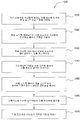
도 1은 본 발명의 하나의 실시예에 따른 듀얼 로드락 챔버의 개략적인 단면도이다.
도 2는 적재/하적 위치에 리프팅 후프(lifting hoop)를 구비한 도 1의 듀얼 로드락 챔버의 개략적인 단면도이다.
도 3은 본 발명의 하나의 실시예에 따른 듀얼 로드락 챔버의 제 2 챔버 용적의 개략적인 상면도이다.
도 4는 본 발명의 하나의 실시예에 따른 듀얼 로드락 챔버의 제 1 챔버 용적의 개략적인 상면도이다.
도 5는 본 발명의 하나의 실시예에 따른 듀얼 로드락 챔버의 제 1 챔버 본체의 개략적인 사시도이다.
도 6은 함께 조립된 제 1 챔버 본체 및 제 2 챔버 본체를 도시하는 사시 단면도이다.
도 7은 히터 기판 지지 어셈블리가 제거된 제 1 챔버 본체 및 제 2 챔버 본체에 형성된 펌핑 채널들을 예시하는 사시 단면도이다.
도 8은 본 발명의 또 다른 실시예에 따른 듀얼 로드락 챔버의 개략적인 단면도이다.
도 9는 본 발명의 실시예들에 따른 듀얼 로드락 챔버들을 포함하는 기판 프로세싱 시스템의 개략적인 평면도이다.
도 10은 본 발명의 하나의 실시예에 따른 기판을 프로세싱하기 위한 방법을 예시하는 순서도이다.
도 11은 본 발명의 또 다른 실시예에 따른 기판을 프로세싱하기 위한 방법을 예시하는 순서도이다.
이해를 용이하게 하기 위하여, 가능한 경우, 도면들에 공통적인 동일한 구성요소들을 지시하도록 동일한 참조 번호들이 이용되었다. 하나의 실시예에서 개시된 구성요소들은 특정한 인용 없이 다른 실시예들에서 유익하게 사용될 수 있다는 것을 고려해야 한다.A more particular description of the invention, briefly summarized above, may be had by reference to embodiments, some of which are illustrated in the appended drawings, in order that the above-recited features of the invention may be understood in detail. It should be noted, however, that the appended drawings illustrate only typical embodiments of this invention and, therefore, should not be construed as limiting the scope thereof, as the invention may admit to other equally effective embodiments .
1 is a schematic cross-sectional view of a dual load lock chamber according to one embodiment of the present invention.
FIG. 2 is a schematic cross-sectional view of the dual load lock chamber of FIG. 1 with a lifting hoop in a loaded / unloaded position.
3 is a schematic top view of a second chamber volume of a dual load lock chamber in accordance with one embodiment of the present invention.
Figure 4 is a schematic top view of a first chamber volume of a dual load lock chamber in accordance with one embodiment of the present invention.
5 is a schematic perspective view of a first chamber body of a dual load lock chamber according to one embodiment of the present invention.
6 is a perspective sectional view showing a first chamber body and a second chamber body assembled together;
7 is a perspective sectional view illustrating pumping channels formed in the first chamber body and the second chamber body from which the heater substrate support assembly is removed.
8 is a schematic cross-sectional view of a dual load lock chamber according to another embodiment of the present invention.
Figure 9 is a schematic plan view of a substrate processing system including dual load lock chambers in accordance with embodiments of the present invention.
10 is a flow chart illustrating a method for processing a substrate in accordance with one embodiment of the present invention.
11 is a flow diagram illustrating a method for processing a substrate in accordance with another embodiment of the present invention.
To facilitate understanding, identical reference numerals have been used, where possible, to designate identical elements that are common to the figures. It should be appreciated that the components disclosed in one embodiment may be advantageously used in other embodiments without specific reference.
본 발명의 실시예들은 반도체 기판 상에 디바이스들을 제조하기 위한 장치 및 방법들을 제공한다. 더욱 구체적으로, 본 발명의 실시예들은 2개의 격리된 챔버 용적들을 포함하되, 적어도 하나의 챔버 용적이 예를 들어, 기판을 반응종에 노출함으로써 기판을 프로세싱하도록 구성되는 듀얼 로드락 챔버(dual load lock chamber)에 관한 것이다.Embodiments of the present invention provide apparatus and methods for fabricating devices on a semiconductor substrate. More specifically, embodiments of the present invention provide a dual load chamber that includes two isolated chamber volumes, wherein at least one chamber volume is configured to process the substrate by, for example, exposing the substrate to a reactive species. lock chamber.
본 발명의 하나의 실시예는 본체 어셈블리에 형성된 적어도 2개의 격리된 챔버 용적들을 갖는 로드락 챔버를 제공한다. 2개의 격리된 챔버 용적들은 수직으로 적층되거나 나란하게 배치될 수 있다. 2개의 챔버 용적들은 독립적으로 동작가능하여 스루풋(throughput)을 증가시킨다. 하나의 실시예에서, 제 1 챔버 용적은 제 1 챔버 용적의 내부에 배치된 기판을 반응종에 노출하도록 구성되어, 예를 들어, 기판으로부터 할로겐 잔류물(halogen residual)을 제거하거나 기판으로부터 포토레지스트(photoresist)를 제거한다. 제 2 챔버 용적은 팩토리 인터페이스(factory interface) 및 이송 챔버의 환경과 같은 인접한 환경들 사이에서 교환하기 위해서만 사용된다. 본 발명의 하나의 실시예는 그 내부의 기판을 가열하기 위한 얇은 피가열 기판 지지체(thin heated substrate support) 및 하나 이상의 프로세싱 가스(processing gas)들을 로드락 챔버에 균일하게 공급하기 위해 얇은 피가열 기판 지지체 상부에 배치된 샤워헤드(showerhead)를 포함하는 로드락 챔버를 제공한다. 하나의 실시예에서, 샤워헤드는 원격지 플라즈마 소스에 연결되어 반응종을 로드락 챔버에 공급한다. 또한, 본 발명의 로드락 챔버는 기판을 프로세스하기 위하여 사용된 챔버 용적 내부에 대칭적인 프로세싱 환경을 생성하기 위한 후프 라이너(hoop liner)를 포함할 수 있다. 본 발명의 하나의 실시예에서, 후프 라이너는 로드락 챔버의 외부에 배치된 기판 이송 로봇들과 기판들을 교환하도록 구성된 하나 또는 그 이상의 리프트 핑거(lift finger)들에 결합될 수 있다.One embodiment of the present invention provides a load lock chamber having at least two isolated chamber volumes formed in a body assembly. The two isolated chamber volumes may be vertically stacked or arranged side by side. The two chamber volumes are independently operable to increase throughput. In one embodiment, the first chamber volume is configured to expose a substrate disposed within the first chamber volume to the reactive species to remove, for example, a halogen residue from the substrate, (photoresist). The second chamber volume is only used to exchange between adjacent environments, such as the factory interface and the environment of the transfer chamber. One embodiment of the present invention includes a thin heated substrate support for heating a substrate therein and a thin heated substrate support for uniformly supplying one or more processing gases to the load lock chamber. A load lock chamber is provided that includes a showerhead disposed on top of the support. In one embodiment, the showerhead is connected to a remote plasma source to supply reactive species to the load lock chamber. The load lock chamber of the present invention may also include a hoop liner for creating a symmetrical processing environment within the chamber volume used to process the substrate. In one embodiment of the present invention, the hoop liners can be coupled to one or more lift fingers configured to exchange substrates with substrate transfer robots disposed outside the load lock chamber.
도 1은 본 발명의 하나의 실시예에 따른 듀얼 로드락 챔버(100)의 개략적인 단면도이다. 듀얼 로드락 챔버(100)는 기판(104)을 이송하기 위한 제 1 챔버 용적(110), 및 기판(104)을 이송 및 프로세싱하기 위한 제 2 챔버 용적(120)을 포함한다. 제 2 챔버 용적(120) 및 제 1 챔버 용적(110)은 수직으로 함께 적층되고 서로로부터 격리된다.1 is a schematic cross-sectional view of a dual
듀얼 로드락 챔버(100)는 챔버 본체 어셈블리(103)를 포함한다. 하나의 실시예에서, 챔버 본체 어셈블리(103)는 제 1 및 제 2 챔버 용적들(120, 110)을 수용하는 통합 구조를 정의하기 위하여 함께 결합된 제 1 챔버 본체(111) 및 제 2 챔버 본체(121)를 포함한다. 하나의 실시예에서, 제 1 챔버 본체(111) 및 제 2 챔버 본체(121)는 수직으로 적층된다. 제 1 챔버 본체(111)가 제 2 챔버 본체(121) 아래에 적층된 것으로 도시되어 있지만, 제 1 챔버 본체(111)가 제 2 챔버 본체(121) 위에 적층될 수 있거나 수평으로 나란하게 위치될 수도 있다는 것이 고려된다.The dual
듀얼 로드락 챔버(100)의 제 2 챔버 용적(120)은 샤워헤드(129), 피가열 기판 지지 어셈블리(132), 및 리프트 후프 어셈블리(144)를 가진다. 샤워헤드(129)는 피가열 기판 지지 어셈블리(132) 상부에 배치된다. 리프트 후프 어셈블리(144)는 피가열 기판 지지 어셈블리(132) 및 기판 이송 로봇들(도시되지 않음)로부터 기판들을 적재(load) 및 하적(unload)하도록 동작할 뿐만 아니라, 제 2 챔버 용적(120) 내부의 프로세싱 환경을 구속하도록 구성된다.The
제 2 챔버 용적(120)은 제 2 챔버 본체(121)의 측벽들(122), 측벽들(122) 상부에 배치된 덮개 라이너(lid liner)(127), 제 2 챔버 본체(121)의 저부 벽(123), 및 제 1 챔버 본체(111)의 상부 벽(118)에 의해 정의된다. 덮개 라이너(127)는 중심 개구부(127c)를 형성하는 내부 립(inner lip)(127a)을 가진다. 내부 립(127a)은 샤워헤드(129) 및 소스 어댑터 판(source adapter plate)(128)을 유지한다. 하나의 실시예에서, 덮개 라이너(127)는 제 2 챔버 본체(121)의 상부에 제거가능하게 배치되어, 챔버 부품들로의 접근을 가능하게 한다.The
샤워헤드(129)는 관통하여 형성된 복수의 관통 구멍들(129a)을 갖는 앞면판(face plate)(129d), 및 중심 개구부(129e)를 갖는 배면판(back plate)(129c)을 포함한다. 앞면판(129d) 및 배면판(129c)은 내부 용적(129b)을 둘러싼다. 내부 용적(129b)은 앞면판(129d)을 관통하여 형성된 관통 구멍들(129a)을 통해 제 2 챔버 용적(120)으로 제공된 가스의 방사상 균일성을 증대시키기 위한 플레넘(plenum)으로서 작용한다.The
소스 어댑터 판(128)은 샤워헤드(129)의 배면판(129c) 상부에 배치된다. 소스 어댑터 판(128)은 샤워헤드(129)의 중심 개구부(129e)와 일치하는 중심 개구부(128a)를 가진다. 원격지 플라즈마 소스(130)는 개구부들(129e 및 128a)에 배치된 석영 삽입부(quartz insert)(131)를 통해 샤워헤드(129)의 내부 용적(129b)과 유체 연통하고 있다. 원격지 플라즈마 소스(130)로부터의 해리(disassociate)된 반응종은 석영 삽입부(131)를 통해 샤워헤드(129)의 내부 용적(129b)으로, 그 다음으로, 샤워헤드(129)의 관통 구멍들(129a)을 통해 제 2 챔버 용적(120)으로 진입한다.The
하나의 실시예에서, 샤워헤드(129)는 플레넘 내부의 반응종에 노출된 내부 용적(129b)의 표면들이 석영에 의해 마감되도록 석영으로 형성되어 제조된다. 석영 삽입부(131) 및 샤워헤드(129)는 원격지 플라즈마 소스(130)로부터 제공된 반응종에 노출되는 것으로부터 금속 챔버 부품들을 차폐하고, 이에 따라, 종 재결합(species recombination), 금속 챔버 부품들의 공격 및 입자 발생을 실질적으로 감소시킨다.In one embodiment, the
원격지 플라즈마 소스(130)는 하나 이상의 프로세싱 가스를 원격지 플라즈마 소스(130)를 통해 상부 챔버 용적(110)으로 공급하기 위한 하나 이상의 가스 패널들에 일반적으로 연결된다. 하나의 실시예에서는, 원격지 플라즈마 소스(130)는 식각 후에 잔류 재료를 제거하기 위한 저감 프로세스(abatement process)를 위하여 프로세싱 가스들을 제공하기 위해 구성된 제 1 가스 패널(101)과, 포토레지스트(photoresist)를 제거하기 위한 애싱 프로세스(ashing process)를 위하여 프로세싱 가스들을 제공하기 위해 구성된 제 2 가스 패널(102)에 연결된다.The
피가열 기판 지지 어셈블리(132)는 듀얼 로드락 챔버(100)의 제 2 챔버 용적(120)에 끼워지도록 구성된다. 피가열 기판 지지 어셈블리(132)는 챔버 본체 어셈블리(103)로부터 실질적으로 열적으로 절연되도록 설치된다. 하나의 실시예에서는, 피가열 기판 지지 어셈블리(132)가 기판(104)을 300℃까지 가열하도록 구성되는 반면, 챔버 본체 어셈블리(103)는 냉각 상태로 유지된다.The heated
하나의 실시예에서, 피가열 기판 지지 어셈블리(132)는 상부 히터 판(133), 상부 히터 판(133)에 부착된 하부 히터 판(134), 및 상부 히터 판(133) 및 하부 히터 판(134) 사이에 배치된 히터(135)를 포함한다. 하나의 실시예에서, 히터(135)는 하부 히터 판(134)의 상부 표면 상에 형성된 채널들 내에 배치될 수 있다. 히터(135)는 저항성 히터(resistive heater) 또는 열 전달 유체(heat transfer fluid)를 흘리도록 배열된 도관(conduit)들일 수 있다. 상부 히터 판(133) 및 하부 히터 판(134)은 볼트(bolt)들, 용접(welding) 또는 납땜(brazing)에 의해 함께 합쳐질 수 있다. 하나의 실시예에서, 상부 히터 판(133) 및 하부 히터 판(134)은 알루미늄(aluminum)과 같은 금속으로 형성될 수 있다.In one embodiment, the heated
상부 히터 판(133)은 기판(104)의 이면(104b)을 지지하도록 구성된다. 하나의 실시예에서, 하부 히터 판(134)은 상부 히터 판(133)의 외부 직경보다 큰 외부 직경을 가진다. 포커스 링(focus ring)(151)은 상부 히터 판(133)의 방사상으로 외부를 향해 노출된 하부 히터 판(134)의 외부 에지(outer edge)(134a) 상에 배치될 수 있다. 포커스 링(151)은 상부 히터 판(133) 및 그 위에 배치된 기판(104)을 둘러싼다. 포커스 링(151)은 기판(104)을 유지하고 프로세싱 동안에 기판(104)의 에지 영역 주위의 프로세싱 레이트를 수정하도록 작용한다. 하나의 실시예에서, 포커스 링(151), 상부 및 하부 히터 판들(133, 134)은 리프트 핑거들(147)을 위한 통로를 제공하도록 구성된 일치하는 절개부(cut out)들(155)을 가질 수 있다.The
피가열 기판 지지 어셈블리(132)는 제 2 챔버 본체(121)의 저부 벽(123) 내의 중심 개구부(123a)를 통해 제 1 챔버 본체(111)의 상부 벽(118) 상에 배치된 열 절연체(thermal insulator)(143) 상에 장착된다. 하나의 실시예에서는, 오목부(118a)가 제 1 챔버 본체(111)의 상부 벽(118) 상에 형성될 수 있다. 오목부(recess)(118a)는 제 1 챔버 본체(111)에 형성된 진공 포트들이 제 2 챔버 용적(120)과 연결되도록 할 수 있다. 피가열 기판 지지 어셈블리(132)는 챔버 본체 어셈블리(103)와 직접 접촉하지 않는다. 제 2 챔버 본체(121) 및 제 1 챔버 본체(111)의 둘 모두를 포함하는 챔버 본체 어셈블리(103) 및 피가열 기판 지지 어셈블리(132) 사이의 열 교환을 방지하기 위하여, 열 절연체(143)가 세라믹(ceramic)과 같은 열 절연성 재료(thermal insulative material)로 형성될 수 있다.The heated
열 절연체(143)는 제 2 챔버 용적(120) 내의 다른 부품들, 예를 들어, 샤워헤드(129) 및 리프트 후프 어셈블리(144)에 대해 피가열 기판 지지 어셈블리(132)를 중심에 놓도록 위치된다. 하나의 실시예에서는, 피가열 기판 지지 어셈블리(132)가 열 팽창 동안에 중심에 놓여진 상태로 유지되는 것을 보장하기 위하여, 열 절연체(143)는 피가열 기판 지지 어셈블리(132)의 중심축(132a)과 정렬한다.The
캔틸레버 튜브(cantilever tube)(136)는 하부 히터 판(134)의 중심 근처에서 이면(134b)으로부터 연장된다. 캔틸레버 튜브(136)는 제 2 챔버 본체(121)의 개구부(153) 및 제 1 챔버 본체(111)의 개구부(152)를 통해 배치된 수직 튜브(137)와 연결되도록 방사상으로 외부를 향해 연장된다. 피가열 기판 지지 어셈블리(132) 및 챔버 본체들(111, 121) 사이의 열 교환을 더욱 회피하기 위하여, 튜브들(136, 137)은 제 2 챔버 본체(121) 또는 제 1 챔버 본체(111)와 접촉하지 않는다. 캔틸레버 튜브(136) 및 수직 튜브(137)는 피가열 기판 지지 어셈블리(132)에 의해 이용될 전력 공급 장치들, 센서들 및 다른 배선을 위한 통로를 제공한다. 하나의 실시예에서, 히터 전원(heater power source)(138), 센서 신호 수신기(139) 및 척킹 제어 유닛(140)은 캔틸레버 튜브(136) 및 수직 튜브(137) 내의 통로를 통해 피가열 기판 지지 어셈블리(132)에 배선으로 연결된다. 하나의 실시예에서, 척킹 제어 유닛(140)은 진공 척킹 기구를 제공하도록 구성된다.A
냉각 어댑터(cooling adaptor)(141)는 제 1 챔버 본체(111)의 외부로부터 수직 튜브(137) 및 제 1 챔버 본체(111)에 결합된다. 냉각 어댑터(141)는 그 내부에 형성된 냉각 채널들(141a)을 가진다. 냉각 어댑터(141) 및 수직 튜브(137), 캔틸레버 튜브(136), 및 피가열 기판 지지 어셈블리(133)의 다른 부품들에 대해 냉각을 제공하기 위하여, 냉각 유체를 위한 소스(142)가 냉각 채널들(141a)에 연결된다. 냉각 어댑터(141)는 프로세싱하는 동안에 일반적으로 냉각 상태로 있고, 이에 따라, 피가열 기판 지지 어셈블리(132) 및 챔버 본체 어셈블리(103) 사이에서 열 절연체(thermal insulator)로서 기능한다.A cooling
하나의 실시예에서는, 균일한 온도 제어를 제공하기 위하여, 바이메탈 커넥터(bi-metal connector)들이 피가열 기판 지지 어셈블리(132)의 다양한 부품들을 연결하기 위해 이용될 수 있다.In one embodiment, bi-metal connectors can be used to connect various components of the heated
피가열 기판 지지 어셈블리(132)의 더욱 상세한 설명은 "Thin Heater Substrate support"(관리 번호 제15750호)라는 명칭으로, 2011년 3월 1일자로 출원된 미국 특허 가출원 제61/448,018호에서 발견될 수 있다.A more detailed description of the heated
또한, 듀얼 로드락 챔버(100)는 외부 로봇들 및 피가열 기판 지지 어셈블리(132) 사이에서 기판들을 이송하고 제 2 챔버 용적(120)에서 대칭적인 프로세싱 환경을 제공하기 위한 리프트 후프 어셈블리(lift hoop assembly)(144)를 포함한다. 리프트 후프 어셈블리(144)는 피가열 기판 지지 어셈블리(132) 주위의 제 2 챔버 용적(120) 내부에 배치된 링-형상(ring-shaped) 후프 본체(146)를 포함한다. 후프 본체(146)는 제 2 챔버 용적(120)의 외부 영역 내에 배치된 리프트(160)에 결합된다. 리프트(160)는 제 2 챔버 용적(120) 내부에서 후프 본체(146)를 수직으로 이동시킨다. 하나의 실시예에서, 리프트(160)는 수직 이동들을 위한 벨로우즈(bellows)(161)를 포함한다. 리프트(160)는 챔버 본체 어셈블리(103)의 외부에 배치된 모터 구동식 액추에이터(motorized actuator)(169)에 결합될 수 있다.The dual
3개 이상의 리프팅 핑거들(147)이 후프 본체(146)에 부착된다. 리프팅 핑거들(147)은 수직으로 아래를 향해 그리고 후프 본체(146)로부터 방사상으로 내부를 향해 연장된다. 리프팅 핑거들(147)은 피가열 기판 지지 어셈블리(132)와, 제 2 챔버 용적(120) 외부의 로봇(robot)들과 같은 기판 이송 디바이스들 사이에서 기판들을 이송하도록 구성된다. 리프팅 핑거들(147)의 선단부(tip)들(147a)은 기판(104)의 에지 영역 근처의 몇몇 지점들에서 기판(104)을 지지하도록 구성된 기판 지지 표면을 형성한다.Three or
도 1은 외부 기판 이송 디바이스들과의 기판 교환을 위한 상부 위치에서의 리프트 후프 어셈블리(144)를 도시한다. 도 2는 리프트 후프 어셈블리(144)가 기판 프로세싱을 위한 하부 위치에 있는 듀얼 로드락 챔버(100)의 개략적인 단면도이다.Figure 1 shows a
후프 본체(146)가 도 2에 도시된 하부 위치에 있을 때, 리프팅 핑거들(147)은 상부 히터 판(133)의 상부 표면(133a) 아래에 위치된다. 후프 본체(146)가 상부 위치로 상승함에 따라, 리프팅 핑거들(147)은 이동하여 기판(104)과 접촉하고, 피가열 기판 지지 어셈블리(132)로부터 기판(104)을 들어올린다. 후프 본체(146)가 도 1에 도시된 상부 위치에 있는 동안, 외부 기판 이송 디바이스(도시되지 않음)는 포트들 중의 하나를 통해 제 2 챔버 용적(120)에 진입하여, 리프팅 핑거들(147)로부터 기판(104)을 제거하고 그 다음으로 새로운 기판(104)을 리프팅 핑거들(147) 상에 놓을 수 있다. 후프 본체(146)가 하부 위치로 다시 하강할 때, 리프팅 핑거들(147) 상에 위치된 새로운 기판(104)은 프로세싱을 위하여 피가열 기판 지지 어셈블리(132) 상에 놓인다.When the
후프 라이너(145)는 후프 본체(146)에 부착된다. 후프 라이너(145)는 후프 본체(146)로부터 수직으로 위를 향해 연장된다. 하나의 실시예에서, 후프 라이너(145)는 실질적으로 납작한 원통형 내부 벽(145a)을 갖는 링(ring)이다. 하나의 실시예에서는, 후프 라이너(145)가 피가열 기판 지지 어셈블리(132) 및 샤워헤드(129) 주위에서 프로세싱 환경을 생성할 수 있도록, 후프 라이너(145)의 내부 벽(145a)의 높이(145b)는 피가열 기판 지지 어셈블리(132)의 두께보다 훨씬 더 크고, 내부 직경은 피가열 기판 지지 어셈블리(132) 및 샤워헤드(129)의 외부 직경들보다 크다. 후프 본체(146)가 도 1에 도시된 상부 위치에 있을 때, 후프 라이너(145)는 덮개 라이너(lid liner)(127) 내부에 형성된 공동(cavity)(127b)으로 진입할 수 있다. 후프 본체(146)가 하부 위치에 있을 때, 후프 라이너(145)의 원통형 내부 벽(145a)은 피가열 기판 지지 어셈블리(132) 바로 위의 영역 및 기판(104) 주위의 제 2 챔버 용적(120) 내부에 원형 구속 벽을 생성하고, 그러므로, 기판(104)을 위한 대칭적인 프로세싱 환경을 제공한다. 하나의 실시예에서, 후프 라이너(145)의 높이(145b)는 샤워헤드(129)의 앞면판(129d) 및 피가열 기판 지지 어셈블리(132) 사이의 수직 공간을 덮을 정도로 충분히 크다. 하나의 실시예에서, 후프 라이너(145)는 석영으로 형성될 수 있다.The
리프트 후프 어셈블리(144)의 더욱 상세한 설명은 "Method and Apparatus for Substrate Transfer and Radical Confinement"(관리 번호 제15745호)라는 명칭으로 2011년 3월 1일자로 출원된 미국 특허 가출원 제61/448,012호에서 발견될 수 있다.A more detailed description of the
제 1 챔버 용적(110)은 제 1 챔버 본체(111) 및 제 1 챔버 본체(111)에 부착된 챔버 바닥부(112)에 의해 정의된다. 제 1 챔버 본체(111)는 상부 벽(118) 및 측벽들(119)을 가진다. 상부 벽(118), 측벽들(119) 및 챔버 바닥부(112)는 제 1 챔버 용적(110)을 둘러싼다. 기판(104)을 지지하고 기판 이송 로봇들과 같은 기판 이송 디바이스들과 기판을 교환하도록 구성된 기판 지지 기구는 제 1 챔버 용적(110) 내에 배치될 수 있다. 하나의 실시예에서는, 기판 지지 기구가 그 이면(104b)으로부터 기판(104)을 지지하기 위한 3개 이상의 지지 핀(supporting pin)들(113)을 포함한다. 하나의 실시예에서는, 지지 핀들(113)이 제 1 챔버 본체(111) 또는 챔버 바닥부(112)로부터 고정된 방식으로 연장될 수 있다. 지지 핀들(113)은 기판 이송 디바이스들과 상호작용하도록 위치된다.The
제 2 챔버 용적(120) 및 제 1 챔버 용적(110)은 진공 시스템(150)에 결합된다. 하나의 실시예에서, 제 2 챔버 용적(120) 및 제 1 챔버 용적(110) 내의 압력들은 서로 독립적으로 제어된다.The
도 3은 샤워헤드(129)가 제거된 제 2 챔버 본체(121)의 개략적인 상면도이다. 제 2 챔버 본체(121)는 측벽들(122) 및 저부 벽(123)을 포함한다. 저부 벽(123)은 제 1 챔버 본체(111)의 상부 벽(118)과 일치하도록 형성되어, 폐쇄된 챔버 용적, 진공을 위한 통로들 및 유틸리티(utility)들(상세한 내용이 뒤따름)을 형성한다. 2개의 개구부들(325)이 측벽들(122)을 관통하여 형성되어, 기판 이송을 가능하게 한다. 슬릿 밸브 도어(slit valve door)가 각각의 개구부(325)의 외부에 부착될 수 있고, 이에 따라, 제 2 챔버 용적(120) 및 2개의 프로세싱 환경들 사이에 인터페이스를 제공한다.3 is a schematic top view of the
도 4는 듀얼 로드락 챔버(100)의 제 1 챔버 용적(110)의 개략적인 상면도이다. 2개의 개구부들(416)은 제 1 챔버 본체(111)의 측벽들(119)을 관통하여 형성되어, 2개의 프로세싱 환경들, 예를 들어, 진공 이송 챔버 및 대기 팩토리 인터페이스(둘 모두 도시되지 않음) 사이에서 기판 이송을 가능하게 한다. 슬릿 밸브 도어는 각각의 개구부(416)의 외부에 부착되어, 진공 이송 챔버 및 대기 팩토리 인터페이스와 같은 2개의 프로세싱 환경들로부터 제 1 챔버 용적(110)을 선택적으로 밀봉할 수 있다. 제 1 챔버 본체(111)는 제 1 챔버 용적(110)을 펌핑하기 위하여 제 1 챔버 용적(110)에 개방된 하부 진공 포트(415)를 가질 수 있다.4 is a schematic top view of the
하나의 실시예에서는, 제 2 챔버 용적(120)을 펌핑하기 위하여, 또한, 상부 진공 포트(454)가 제 1 챔버 본체(111)를 관통하여 형성된다.In one embodiment, an
도 5는 본 발명의 하나의 실시예에 따른 제 1 챔버 본체(111)의 개략적인 사시도이다. 오목부(118a)가 제 1 챔버 본체(111)의 상부 벽(118) 상에 형성된다. 오목부(118a)는 피가열 기판 지지 어셈블리(132)가 제 2 챔버 용적(120)에서 낮게 안착하도록 하고, 이에 따라, 제 2 챔버 용적(120)을 감소시킨다. 피가열 기판 지지 어셈블리(132)를 지지하기 위한 열 절연체(143)(도 1에 도시됨)를 고정하기 위하여 중심 노치(center notch)(543)가 오목부(118a) 내부에 형성될 수 있다. 상부 진공 포트(454)는 제 1 챔버 본체(111)의 측벽들(119)을 관통하여 형성되고, 제 1 챔버 본체(111)의 상부 벽(118)에 형성된 오목부(118a)에 개방된다. 따라서, 오목부(118a)는 또한 제 2 챔버 용적(120)으로의 펌핑 채널이 제 1 챔버 본체(111) 내부에 형성하도록 한다. 대안적으로, 진공 포트(454)는 오목부(118a) 외부에 형성되어 제 2 챔버 본체(121)의 저부 벽(123) 상에 형성된 포트와 일치할 수 있다.5 is a schematic perspective view of a
하나의 실시예에서는, 적어도 하나의 글랜드(511a)가 오목부(118a) 주위에 형성된다. 밀봉부가 각각의 글랜드(511a)에 배치되어 제 2 챔버 본체(121) 및 제 1 챔버 본체(111) 사이에 진공 밀봉부를 형성할 수 있다. 하나의 실시예에서는, 2개의 글랜드들(511a)이 제 1 챔버 본체(111)의 상부 벽(118) 상에 형성되어, 증가된 진공 밀봉을 제공할 수 있다.In one embodiment, at least one
도 6은 함께 조립된 제 2 챔버 본체(121) 및 제 1 챔버 본체(111)를 도시하는 사시 단면도이다. 제 2 챔버 본체(121)의 저부 벽(123) 상에 형성된 중심 개구부(123a)는 제 2 챔버 용적(120)의 내부를 제 1 챔버 본체(111)의 상부 벽(118) 상의 오목부(118a)와 연결한다. 따라서, 제 2 챔버 본체(121)가 제 1 챔버 본체(111)에 부착될 때, 상부 진공 포트(454)는 제 2 챔버 용적(120)과 유체 연통하고 있다.6 is a perspective sectional view showing the
도 7은 히터 기판 지지 어셈블리(132)가 제거된 제 1 챔버 본체(111) 및 제 2 챔버 본체(121)의 사시 단면도이다. 도 7에는, 하부 진공 포트(415)가 도시되어 있다. 제 2 챔버 본체(121) 및 제 1 챔버 본체(111)는 진공 밀봉부를 얻도록 다양한 방법들로 함께 합쳐질 수 있다. 하나의 실시예에서는, 제 2 챔버 본체(121)가 제 1 챔버 본체(111)에 볼트 결합된다. 또 다른 실시예에서는, 제 1 챔버 본체(111) 및 제 2 챔버 본체(121)가 함께 납땜되어 누설의 위험을 감소시킬 수 있고 공차에 대한 쟁점들을 제거할 수 있다.7 is a perspective sectional view of the
도 8은 본 발명의 또 다른 실시예에 따른 듀얼 로드락 챔버(800)의 개략적인 단면도이다. 듀얼 로드락 챔버(800) 내의 램프 어셈블리(810)가 듀얼 로드락 챔버(100) 내의 원격지 플라즈마 소스(130) 대신에 이용된다는 것을 제외하고는, 듀얼 로드락 챔버(800)는 듀얼 로드락 챔버(100)와 유사하다. 석영 윈도우(quartz window)(811)는 덮개 라이너(127) 상부에 배치된다. 램프 어셈블리(810)는 석영 윈도우(811)의 외부에 위치된다. 램프 어셈블리(810)로부터의 복사 에너지가 석영 윈도우(811)를 통해 제 2 챔버 용적(120)으로 보내질 수 있다. 가스 소스(812)는 제 2 챔버 용적(120)과 유체 연통하고 있어, 퍼징(purging)을 위하여 프로세싱 가스 및/또는 불활성 가스(inert gas)를 제공한다.8 is a schematic cross-sectional view of a dual
도 9는 본 발명의 실시예들에 따른 하나 이상의 듀얼 로드락 챔버들(100)을 포함하는 기판 프로세싱 시스템(900)의 개략적인 평면도이다. 또한, 듀얼 로드락 챔버(800)가 듀얼 로드락 챔버들(100) 대신에 이용될 수 있다.9 is a schematic plan view of a
시스템(900)은 진공-기밀(vacuum-tight) 프로세싱 플랫폼(904), 팩토리 인터페이스(902), 및 시스템 제어기(944)를 포함한다. 플랫폼(904)은 진공 기판 이송 챔버(936)에 결합되는 복수의 프로세싱 챔버들(918) 및 적어도 하나의 듀얼 로드락 챔버(100)를 포함한다. 하나의 실시예에서는, 이송 챔버(936)가 4개의 측면들을 가질 수 있다. 각각의 측면(920)은 한 쌍의 프로세싱 챔버들(918) 또는 로드락 챔버들(100)과 연결하도록 구성된다. 도 9에 도시된 바와 같이, 6개의 프로세싱 챔버들(918)은 이송 챔버(936)의 3개의 측면들(920)에 결합되고, 2개의 듀얼 로드락 챔버들(100)은 이송 챔버(936)의 네 번째 측면(920)에 결합된다. 팩토리 인터페이스(902)는 듀얼 로드락 챔버들(100)에 의해 이송 챔버(936)에 결합된다.The
하나의 실시예에서는, 팩토리 인터페이스(902)가 적어도 하나의 도킹 스테이션(docking station)(908) 및 적어도 하나의 팩토리 인터페이스 로봇(914)을 포함하여, 기판들의 이송을 용이하게 한다. 도킹 스테이션(908)은 하나 이상의 전방 개방 통합 포드(FOUP : front opening unified pod)를 수용하도록 구성된다. 4개의 FOUP들(906)이 도 9의 실시예에 도시되어 있다. 로봇(914)의 일 단부 상에 배치된 블레이드(916)를 갖는 팩토리 인터페이스 로봇(914)은 듀얼 로드락 챔버들(100)을 통한 프로세싱을 위해 기판을 팩토리 인터페이스(902)로부터 프로세싱 플랫폼(904)으로 이송하도록 구성된다.In one embodiment, the
듀얼 로드락 챔버들(100)의 각각은 팩토리 인터페이스(902)에 결합된 2개의 포트들 및 이송 챔버(936)에 결합된 2개의 포트들을 가진다. 듀얼 로드락 챔버들(100)은 이송 챔버(936)의 진공 환경 및 팩토리 인터페이스(902)의 실질적으로 주위(예를 들어, 대기) 환경 사이에서 기판을 전달하는 것을 용이하게 하기 위해 듀얼 로드락 챔버들(100)을 펌프 다운(pump down) 및 통기(vent)하는 압력 제어 시스템(도시되지 않음)에 결합된다.Each of the dual
이송 챔버(936)는 듀얼 로드락 챔버들(100) 및 프로세싱 챔버들(918) 사이에서 기판(924)을 이송하기 위하여 내부에 배치된 진공 로봇(937)을 가진다. 하나의 실시예에서, 진공 로봇(937)은 각각이 듀얼 로드락 챔버들(100) 및 프로세싱 챔버들(918) 사이에서 기판(924)을 이송할 수 있는 2개의 블레이드들(940)을 가진다. 하나의 실시예에서, 진공 로봇(937)은 2개의 기판들을 2개의 프로세싱 챔버들(918) 또는 2개의 로드락(load lock)들(100)에 동시에 이송하도록 구성된다.The
하나의 실시예에서는, 적어도 하나의 프로세스 챔버들(918)이 식각 챔버이다. 예를 들어, 식각 챔버는 Applied Material, Inc로부터 입수가능한 비결합식 플라즈마 소스(DPS : decoupled plasma source) 챔버일 수 있다. DPS 식각 챔버는 고밀도 플라즈마를 생성하기 위하여 유도성 소스를 이용하고, 기판에 바이어스(bias)를 인가하기 위하여 라디오-주파수(RF : radio-frequency) 파워의 소스를 포함한다. 대안적으로, 프로세스 챔버들(918) 중의 적어도 하나는 또한 Applied Materials, Inc로부터 입수가능한 HART™, E-MAX®, DPS®, DPS Ⅱ, PRODUCER E, 또는 ENABLER® 식각 챔버 중의 하나일 수 있다. 다른 제조업체들로부터의 식각 챔버들을 포함하는 다른 식각 챔버들이 사용될 수 있다. 식각 챔버들은 그 내부에서 기판(924)을 식각하기 위하여 할로겐-함유(halogen-containing) 가스를 이용할 수 있다. 할로겐-함유 가스의 예들은 브롬화수소(HBr), 염소(Cl2), 사불화탄소(carbon tetrafluoride)(CF4) 등을 포함한다. 기판(924)을 식각한 후, 할로겐-함유 잔류물들은 기판 표면 상에 남겨질 수 있다.In one embodiment, at least one of the
할로겐-함유 잔류물들은 듀얼 로드락 챔버들(100)에서 열처리 프로세스에 의해 제거될 수 있다. 예를 들어, 열처리 프로세스는 하나 또는 둘 모두의 듀얼 로드락 챔버들(100)의 제 2 챔버 용적(120)에서 수행될 수 있다. 대안적으로, 하나 또는 둘 모두의 듀얼 로드락 챔버들(100)의 제 2 챔버 용적(120)에서 애싱 프로세스가 수행될 수 있다.The halogen-containing residues may be removed by a heat treatment process in dual
시스템 제어기(944)는 프로세싱 시스템(900)에 결합된다. 시스템 제어기(944)는 시스템(900)의 프로세스 챔버들(918)의 직접 제어를 이용하여, 또는 대안적으로, 프로세스 챔버들(918) 및 시스템(900)과 연관된 컴퓨터들(또는 제어기들)을 제어함으로써 시스템(900)의 동작을 제어한다. 동작 시에, 시스템 제어기(944)는 각각의 챔버들 및 시스템 제어기(944)로부터의 데이터 수집 및 피드백을 가능하게 하여 시스템(900)의 성능을 최적화한다.A
시스템 제어기(944)는 일반적으로 중앙 프로세싱 유닛(CPU : central processing unit)(938), 메모리(939), 및 지원 회로(942)를 포함한다. CPU(938)는 산업적인 환경에서 이용될 수 있는 임의의 형태의 범용 컴퓨터 프로세서 중의 하나일 수 있다. 지원 회로(942)는 통상적으로 CPU(938)에 결합되고, 캐시(cache), 클록 회로들, 입력/출력 서브시스템들, 전력 공급 장치들 등을 포함할 수 있다. 도 10을 참조하여 아래에 설명된 할로겐-함유 잔류물들을 제거하기 위한 방법(1000) 및/또는 도 11을 참조하여 설명된 애싱을 위한 방법(1100)과 같은 소프트웨어 루틴들은, CPU(938)에 의해 실행될 때, CPU(938)를 특정 용도 컴퓨터(제어기)(944)로 변환한다. 또한, 소프트웨어 루틴들은 시스템(900)으로부터 원격으로 위치되는 제 2 제어기(도시되지 않음)에 의해 저장 및/또는 실행될 수 있다.The
도 10은 본 발명의 하나의 실시예에 따른 기판을 프로세싱하기 위한 방법(1000)을 예시하는 순서도이다. 구체적으로, 방법(1000)은 기판으로부터 할로겐-함유 잔류물을 제거하도록 구성된다. 방법(1000)은 도 9에서 설명된 바와 같은 프로세싱 시스템(900)에서 수행될 수 있다. 방법(1000)은 다른 제조업체들로부터의 프로세싱 시스템들을 포함하는 다른 적당한 프로세싱 시스템들에서 수행될 수 있다는 것이 고려된다.10 is a flow diagram illustrating a
방법(1000)은 박스(1010)에서, FOUP들(906) 중의 하나로부터 듀얼 로드락 챔버(100)로 그 위에 배치된 층을 가지는 기판을 이송하고 기판을 포함하는 챔버 용적을 이송 챔버(936)의 진공 레벨과 동일한 진공 레벨로 펌핑 다운(pumping down) 함으로써 시작된다. 하나의 실시예에서는, 듀얼 로드락 챔버(100)로 이송된 기판이 팩토리 인터페이스(902)로부터 듀얼 로드락 챔버(100)의 제 1 챔버 용적(110)으로만 이송될 수 있다. 이와 같은 방식으로, 프로세싱된 기판 및 프로세싱되지 않은 기판 사이의 상호 오염이 유익하게도 감소된다.The
또 다른 실시예에서는, 듀얼 로드락 챔버(100)로 이송된 기판이 로드락 챔버(100)의 제 2 챔버 용적(120) 내의 피가열 기판 지지 어셈블리(132)에 의해 미리 결정된 온도로 예열될 수 있다. 하나의 실시예에서는, 기판이 섭씨 약 20도 및 섭씨 약 400도 사이의 온도로 예열될 수 있다.In another embodiment, the substrate transferred to the dual
박스(1020)에서는, 듀얼 로드락 챔버(100) 및 이송 챔버(936) 내의 압력이 실질적으로 동일해진 후, 진공 로봇(937)이 듀얼 로드락 챔버(100)로부터 프로세싱 챔버들(918) 중의 하나로 기판을 이송한다.In the box 1020 a
박스(1030)에서는, 기판이 프로세싱 챔버(918) 중의 하나에서 식각되어 기판 상에 희망하는 특징부들 및 패턴들을 형성한다.In
하나의 실시예에서는, 적어도 할로겐-함유 가스를 갖는 가스 혼합물을 공급함으로써, 기판이 프로세싱 챔버들(918) 중의 하나에서 식각된다. 패터닝된 마스크는 포토레지스트(photoresist) 및/또는 하드마스크(hardmask)를 포함할 수 있다. 할로겐-함유 가스의 적당한 예들은 브롬화수소(HBr), 염소(Cl2), 사불화탄소(CF4) 등을 포함하지만, 이것으로 제한되지 않는다. 폴리실리콘(polysilicon)을 식각하기에 적당한 예시적인 실시예에서는, 프로세싱 챔버(918)로 공급되는 가스 혼합물이 20 sccm 및 약 60 sccm 사이 예를 들어, 약 40 sccm과 같이, 약 20 sccm 및 약 300 sccm 사이의 유량(flow rate)으로 브롬화수소(HBr) 및 염소(Cl2) 가스를 포함하는 가스 혼합물을 제공한다. 브롬화수소(HBr) 및 염소(Cl2) 가스는 약 1:15와 같이, 약 1:0 및 약 1:30 사이의 범위의 가스 비율을 가질 수 있다. 불활성 가스가 가스 혼합물과 함께 프로세싱 챔버(918)로 공급될 수 있다. 불활성 가스의 적당한 예들은 질소(N2), 아르곤(Ar), 헬륨(He) 등을 포함할 수 있다. 하나의 실시예에서는, N2와 같은 불활성 가스가 가스 혼합물과 함께 약 0 sccm 및 약 40 sccm 사이, 예를 들어, 약 20 sccm과 같이, 약 0 sccm 및 약 200 sccm 사이의 유량으로 공급될 수 있다. 일산화탄소(CO : carbon monoxide)와 같은 환원 가스가 가스 혼합물과 함께 공급될 수 있다. 식각 프로세스를 위한 플라즈마 파워(plasma power)는 약 500 와트(watt) 및 약 1500 와트, 예를 들어, 약 1100 와트와 같이, 약 200 와트 및 약 3000 와트 사이에서 유지될 수 있고, 바이어스 파워는 약 0 와트 및 약 80 와트, 예를 들어, 약 20 와트와 같이, 약 0 와트 및 약 300 와트 사이에서 유지될 수 있다. 프로세스 압력은 약 2 mTorr 및 약 20 mTorr 사이, 예를 들어, 약 4 mTorr와 같이, 약 2 mTorr 및 약 100 mTorr 사이에서 제어될 수 있고, 기판 온도는 섭씨 약 0도 및 섭씨 약 100도 사이, 예를 들어, 섭씨 약 45도와 같이, 섭씨 약 0도 및 섭씨 약 200도 사이에서 유지될 수 있다.In one embodiment, the substrate is etched in one of the
식각 프로세스 동안에, 식각된 재료들은 식각제 화학물질의 성분들뿐만 아니라, 만약 있다면, 마스크 층들의 성분들 및 식각 프로세스의 부산물(by-product)들과 결합할 수 있고, 이에 따라, 할로겐-함유 잔류물들을 형성할 수 있다. 하나의 실시예에서, 식각될 기판 상의 재료들은 포토레지스트층, 하드 마스크층, 바닥 반사방지 코팅(BARC : bottom anti-reflective coating), 폴리실리콘, 결정 실리콘, 게이트 산화물, 질화티타늄(TiN)과 같은 금속 게이트, 및 산화알루미늄(Al2O3), 하프늄(hafnium) 함유 산화물과 같은 고-K(high-K) 재료들을 포함할 수 있다. 하드 마스크층의 적당한 예들은 질화실리콘, TEOS, 산화실리콘, 비정질 탄소, 및 탄화실리콘을 포함한다. 할로겐-함유 잔류물들은 기판의 표면들 상에 퇴적한다. 할로겐-함유 잔류물은, 대기압들 및/또는 수증기에 노출될 경우, 브롬(Br2), 염소(Cl2), 염화수소(HCl), 브롬화수소(HBr) 등과 같은 가스 반응물들을 방출(예를 들어, 가스 방출)할 수 있다. 이러한 반응물들의 방출은 기판 이송 동안에, 도 9에 설명된 바와 같이 진공-기밀 프로세싱 플랫폼(904) 및 팩토리 인터페이스(902)와 같은 프로세싱 장치 및 팩토리 인터페이스들의 부식들 및 입자 오염을 야기시킬 수 있다. Cu, Al, W와 같은 금속층들이 기판 표면에 노출되는 실시예들에서는, 방출된 가스 반응물들이 아래에서 설명되는 발명의 프로세스에 의해 제거되지 않을 경우, 금속층이 상기 방출된 가스 반응물들에 의해 부식될 수 있고, 그것에 의해 기판 상에 형성된 디바이스들의 성능을 나쁘게 열화시킬 수 있다.During the etching process, the etched materials can be combined with the components of the etch chemistry, as well as, if any, components of the mask layers and by-products of the etch process, Water can be formed. In one embodiment, the materials on the substrate to be etched are selected from the group consisting of a photoresist layer, a hard mask layer, a bottom anti-reflective coating (BARC), polysilicon, crystalline silicon, gate oxide, titanium nitride Metal gates, and high-K materials such as aluminum oxide (Al 2 O 3 ), hafnium-containing oxides. Suitable examples of hardmask layers include silicon nitride, TEOS, silicon oxide, amorphous carbon, and silicon carbide. The halogen-containing residues are deposited on the surfaces of the substrate. The halogen-containing residues can be used to release gaseous reactants such as bromine (Br 2 ), chlorine (Cl 2 ), hydrogen chloride (HCl), hydrogen bromide (HBr) and the like , Gas emission). The release of these reactants may cause erosion and particle contamination of the processing devices and factory interfaces, such as the vacuum-
또한, 할로겐들은 식각 이외의 방식으로 진공 환경에서 프로세싱되는 기판들의 표면 상에 존재할 수 있다. 그러므로, 할로겐들은 본 명세서에서 설명된 방법 및 장치를 이용하여 그러한 기판들로부터 제거될 수 있다는 것이 고려된다.In addition, halogens can be present on the surface of substrates that are processed in a vacuum environment in a manner other than etching. It is therefore contemplated that halogens may be removed from such substrates using the methods and apparatus described herein.
박스(1040)에서는, 프로세싱된(예를 들어, 식각된) 기판이 듀얼 로드락 챔버(100)의 제 2 챔버 용적(120)으로 이송되어, 팩토리 인터페이스 또는 다른 위치에서 대기 조건들 또는 수증기에 노출되기 전에 박스(1030)의 프로세싱 동안에 발생된 할로겐 함유 잔류물들을 기판으로부터 제거한다. 식각 프로세싱 후, 이송 챔버(936) 내의 진공 로봇(937)은 프로세싱 챔버들(918) 중의 하나로부터 로드락 챔버(100)의 제 2 챔버 용적(120) 내의 리프팅 핑거들(147)로 식각된 기판을 이송한다. 리프팅 핑거들(147)은 식각된 기판을 하강하고 피가열 기판 지지 어셈블리(132)로 이송한다.In the
박스(1050)에서는, 식각된 기판 상에서 열처리 프로세스가 수행되어, 식각된 기판 표면 상의 할로겐-함유 잔류물들을 제거한다. 피가열 기판 지지 어셈블리(132) 내의 히터(135)는 기판의 표면의 온도가 상승하게 하도록 이용되고, 그것에 의해, 식각된 기판 표면 상에 배치된 할로겐계 반응물들이 방출 및/또는 가스로 방출되도록 한다. 피가열 기판 지지 어셈블리(132)는 약 5초 및 약 30초 사이에, 섭씨 약 150도 및 섭씨 약 300도 사이, 예를 들어, 섭씨 약 250도와 같이, 섭씨 약 20도 및 섭씨 약 1000도 사이의 온도로 기판을 가열한다. 피가열 기판 지지 어셈블리(132)에 의한 기판의 급속 가열은 프로세싱 챔버들 중의 하나에서 잔류물들이 제거될 경우에 마주치게 될 프로세스 사이클 시간(process cycle time)을 증가시키지 않으면서, 식각된 기판 상의 할로겐-함유 잔류물들이 제거되도록 한다. 하나의 실시예에서는, 식각된 기판 상의 할로겐-함유 잔류물들이 그로부터 제거될 때까지, 기판이 미리 결정된 시간 주기로 피가열 기판 지지 어셈블리(132)에 의해 가열될 수 있다. 시간 또는 종점(endpoint)이 센서 신호 수신기(139)에 연결된 센서들을 이용하여 결정될 수 있다. 식각된 기판은 약 30초 내지 약 90초 사이와 같이, 약 10초 내지 약 120초 사이 동안에, 섭씨 약 250도와 같이, 섭씨 약 150도 및 섭씨 약 300도 사이의 온도에서 가열될 수 있다.In
하나의 실시예에서는, 가스 혼합물이 원격지 플라즈마 소스(130)를 통해 듀얼 로드락 챔버(100)의 제 2 챔버 용적(120)으로 제공될 수 있다. 원격지 플라즈마 소스(130)는 가스 혼합물을 이온화한다. 해리된 이온들 및 화학종(species)은 가스 방출된 할로겐계 반응물들의 비-부식(non-corrosive) 휘발성 화합물들로의 변환을 촉진하고, 그것에 의해, 식각된 기판 표면으로부터의 할로겐-함유 잔류물들의 제거 효율을 증가시킨다. 가스 혼합물은 O2, O3, 수증기(H2O)와 같은 산소-함유 가스, 또는 H2, 포밍 가스(forming gas), 수증기(H2O), 알칸(alkane)들, 알켄(alkene)들 등과 같은 수소-함유 가스, 또는 질소 가스(N2), 아르곤(Ar), 헬륨(He) 등과 같은 불활성 가스를 포함할 수 있다. 예를 들어, 가스 혼합물은 산소, 질소, 및 수소-함유 가스를 포함할 수 있다. 하나의 실시예에서는, 수소-함유 가스가 수소(H2) 및 수증기(H2O) 중의 적어도 하나이다. 마스크층들이 기판 상에 존재하는 실시예들에서는, 마스크층들이 할로겐-함유 잔류물들과 동시에 제거될 수 있고, 예를 들어, 로드락 챔버에서 마스크의 포토레지스트가 박리된다.In one embodiment, a gas mixture may be provided through the
하나의 실시예에서는, 원격지 플라즈마 소스가 약 500 와트 및 6000 와트 사이에서 플라즈마 파워를 제공할 수 있다. 플라즈마가 존재하는 실시예들에서는, Ar, He 또는 N2와 같은 불활성 가스가 가스 혼합물과 함께 공급될 수 있다.In one embodiment, the remote plasma source can provide plasma power between about 500 Watts and 6000 Watts. In embodiments where a plasma is present, an inert gas such as Ar, He or N 2 may be supplied with the gas mixture.
대안적으로, 듀얼 로드락 챔버(800)가 듀얼 로드락 챔버(100) 대신에 이용될 때에는, 식각된 기판을 가열하면서, 가스 혼합물이 가스 소스(812)로부터 제 2 챔버 용적(120)으로 공급될 수 있다. 식각된 기판은 가스 혼합물에 노출되고 가스 혼합물과 반응한다. 가스 혼합물은 가스 방출된 할로겐계 반응물들을, 듀얼 로드락 챔버(100) 외부로 펌핑되는 비-부식 휘발성 화합물들로 변환한다.Alternatively, when a dual
선택적으로, 기판은 진공 환경으로부터 제거하기 전에, 추가적인 프로세싱을 위해 시스템의 프로세싱 챔버(918) 중의 하나로 복귀될 수 있다. 박스(1050)에서의 할로겐 제거 프로세스 후에, 기판은 추후의 프로세싱 동안에 프로세싱 챔버들로 할로겐들을 도입하지 않을 것이고, 그것에 의해 프로세싱 챔버들에 대한 손상을 방지할 것이다.Optionally, the substrate may be returned to one of the
박스(1060)에서는, 제 2 챔버 용적(120)이 대기압으로 통기된다. 선택적으로, 피가열 기판 지지 어셈블리(132)는 통기하는 동안에 냉각 어댑터(141)를 통해 기판 온도를 희망하는 레벨로 낮추기 위해 냉각될 수 있다. 하나의 실시예에서는, FOUP들(906)에 대해 손상을 야기하지 않으면서 식각된 기판을 FOUP들(906)로 복귀하는 것을 가능하게 하는 섭씨 약 10도 및 섭씨 약 125도 사이의 범위의 온도로 식각된 기판이 냉각될 수 있다.In
박스(1070)에서는, 제 2 챔버 용적(120) 및 팩토리 인터페이스(902)의 압력들이 일치되면, 로드락 챔버(100)의 제 2 챔버 용적(120)으로부터 식각된 기판이 FOUP들(906) 중의 하나로 복귀된다.In
본 발명의 또 다른 실시예에서는, 본 발명의 실시예들에 따라 포토레지스트 제거 프로세스가 듀얼 로드락 챔버에서 수행될 수 있다. 도 11은 기판이 도 9의 기판 프로세싱 시스템(900)과 같은 기판 프로세싱 시스템을 나올 때, 로드락 챔버에서 기판으로부터 포토레지스트를 제거하는 것을 포함하는 방법(1100)을 예시하는 순서도이다.In yet another embodiment of the present invention, a photoresist removal process may be performed in a dual load lock chamber in accordance with embodiments of the present invention. 11 is a flow chart illustrating a
방법(1100)이 박스(1150)에서 설명된 애싱 프로세스를 포함하는 것을 제외하고는, 방법(1100)은 도 10의 방법(1000)과 유사하다.The
박스(1150)에서는, 듀얼 로드락 챔버(100)의 제 2 챔버 용적에서 애싱 프로세스가 수행되어, 기판들로부터 포토레지스트를 제거한다. 산소계(oxygen-based) 플라즈마가 이용될 수 있다. 예를 들어, O2와 같은 산화 가스는 100 내지 10000 sccm의 유량으로 원격지 플라즈마 소스(130)로 흘려진다. 600 내지 6000 와트의 RF 에너지가 원격지 플라즈마 소스(130)에 가해질 때, 산화 가스는 플라즈마로 형성된다. 제 2 챔버 용적(120) 내의 가스 압력은 0.3 내지 3 Torr로 유지될 수 있다. 기판의 온도는 섭씨 15 내지 300도로 유지될 수 있다. O2, O3, N2O, H2O, CO, CO2, 알콜들, 및 이 가스들의 다양한 조합들을 포함하지만, 이것으로 제한되지는 않는 다양한 산화 가스들이 이용될 수 있다. 발명의 다른 실시예들에서는, N2, H2O, H2, 포밍 가스, NH3, CH4, C2H6, 다양한 할로겐화된 가스들(CF4, NF3, C2F6, C4F8, CH3F, CH2F2, CHF3), 이 가스들의 조합들 등을 포함하지만, 이것으로 제한되지 않는 비산화(nonoxidizing) 가스들이 이용될 수 있다.In
방법(1000 또는 1100)은 유입 기판들에 대해 배타적으로 제 1 챔버 용적(110)을 이용하고 유출 기판들에 대해 배타적으로 제 2 챔버 용적(120)을 이용함으로써 듀얼 로드락 챔버(100)를 통합할 수 있다. 유입 및 유출 기판들을 별개의 경로들에 유지함으로써, 본 발명의 실시예들은 프로세싱된 기판 및 프로세싱되지 않은 기판 사이의 상호 오염을 효과적으로 방지한다.The
상기한 것은 본 발명의 실시예들에 대한 것이지만, 발명의 다른 그리고 더 이상의 실시예들이 그 기본 범위로부터 이탈하지 않으면서 고안될 수 있고, 그 범위는 뒤따르는 청구항들에 의해 결정된다.While the foregoing is directed to embodiments of the present invention, other and further embodiments of the invention may be devised without departing from the basic scope thereof, and the scope thereof is determined by the claims that follow.
Claims (15)
상기 주위 환경과 상기 진공 환경 사이에서 상기 제 1 챔버 용적 및 상기 제 2 챔버 용적내의 압력을 제어하도록 동작가능한 압력 제어 시스템;
상기 제 2 챔버 용적 내에 배치된 피가열 기판 지지 어셈블리로서, 상기 제 2 챔버 용적내 플라즈마 프로세싱 동안에 상기 피가열 기판 지지 어셈블리 상의 기판을 지지 및 가열하도록 구성된 피가열 기판 지지 어셈블리(heated substrate support assembly);
상기 기판을 리프트하도록 구성되고 상기 피가열 기판 지지 어셈블리를 둘러싸는 상기 제 2 챔버 용적 내에 배치된 리프트 후프 어셈블리(lift hoop assembly)로서, 상기 리프트 후프 어셈블리는 링-형상(ring-shaped) 후프 본체, 프로세싱 영역을 정의하는 상기 후프 본체로부터 수직으로 위쪽으로 연장되고 상기 후프 본체위에 배치된 후프 라이너, 및 상기 후프 본체에 부착되고 상기 후프 본체 밑에 수직으로 아래쪽으로 그리고 상기 후프 본체로부터 방사상으로 안쪽으로 연장되는 3개 이상의 리프팅 핑거(lifting finger)들을 포함하는, 상기 리프트 후프 어셈블리; 및
플라즈마를 상기 제 2 챔버 용적으로 공급하기 위해 상기 제 2 챔버 용적에 연결된 원격지 플라즈마 소스로서, 산소-함유 가스, 수소 함유 가스 및 불활성 가스를 함유하는 가스 혼합물을 이온화하는, 상기 원격지 플라즈마 소스를 포함하는, 로드락 챔버.A chamber body defining a first chamber volume and a second chamber volume that are isolated from one another, the first chamber volume having a first chamber opening configured for substrate transfer and a second chamber opening configured for vacuum environment wherein the second chamber volume is selectively connected to the ambient environment and the vacuum environment through a third opening and a fourth opening;
A pressure control system operable to control a pressure in the first chamber volume and the second chamber volume between the ambient environment and the vacuum environment;
A heated substrate support assembly disposed within the second chamber volume, the heated substrate support assembly configured to support and heat a substrate on the heated substrate support assembly during plasma processing in the second chamber volume;
A lift hoop assembly configured to lift the substrate and disposed within the second chamber volume surrounding the heated substrate support assembly, the lift hoop assembly comprising a ring-shaped hoop body, A hoop liner vertically upwardly extending from the hoop body defining a processing region and disposed on the hoop body; and a hoop liner attached to the hoop body and extending radially inwardly below and vertically below the hoop body The lift hoop assembly comprising three or more lifting fingers; And
A remote plasma source coupled to the second chamber volume for supplying a plasma to the second chamber volume, the remote plasma source for ionizing a gas mixture containing an oxygen-containing gas, a hydrogen containing gas and an inert gas, , Load lock chamber.
상기 피가열 기판 지지 어셈블리 및 상기 챔버 본체 사이의 상기 제 2 챔버 용적 내에 배치된 열 절연체(thermal insulator)를 더 포함하고, 상기 피가열 기판 지지 어셈블리는 상기 챔버 본체와 직접 접촉하지 않는, 로드락 챔버.The method according to claim 1,
Further comprising a thermal insulator disposed within the second chamber volume between the heated substrate support assembly and the chamber body, wherein the heated substrate support assembly is in direct contact with the chamber body, .
상기 챔버 본체는,
상부 벽, 측벽들, 및 챔버 바닥부를 갖는 제 1 챔버 본체로서, 상기 상부 벽, 측벽들 및 챔버 바닥부가 상기 제 1 챔버 용적을 정의하는 제 1 챔버 본체;
상기 제 1 챔버 본체의 상기 상부 벽 상에 적층된 제 2 챔버 본체로서, 상기 제 2 챔버 본체 및 상기 제 1 챔버 본체의 상기 상부 벽이 상기 제 2 챔버 용적을 정의하는 상기 제 2 챔버 본체를 포함하는, 로드락 챔버.The method of claim 2,
The chamber body includes:
A first chamber body having a top wall, side walls, and a chamber bottom, the top wall, the sidewalls, and the chamber bottom defining a first chamber volume;
A second chamber body stacked on the top wall of the first chamber body, the second chamber body and the top wall of the first chamber body including the second chamber body defining the second chamber volume The load lock chamber.
상기 피가열 기판 지지 어셈블리는,
그 위에서 기판을 지지하기 위한 상부 표면을 갖는 상부 히터 판;
상기 상부 히터 판의 하부 표면에 부착된 하부 히터 판; 및
상기 상부 히터 판 및 상기 하부 히터 판 사이에 배치된 히터를 포함하는, 로드락 챔버.The method of claim 3,
The heated substrate support assembly includes:
An upper heater plate having an upper surface thereon for supporting the substrate;
A lower heater plate attached to a lower surface of the upper heater plate; And
And a heater disposed between the upper heater plate and the lower heater plate.
상기 피가열 기판 지지 어셈블리는 상기 하부 히터 판의 중심에 부착된 캔틸레버 튜브를 더 포함하는, 로드락 챔버.The method of claim 4,
Wherein the heated substrate support assembly further comprises a cantilever tube attached to the center of the lower heater plate.
상기 피가열 기판 지지 어셈블리는 상기 기판을 상기 상부 히터 판의 상기 상부 표면에 척킹(chucking)하도록 구성된 척킹 기구를 더 포함하는, 로드락 챔버.The method of claim 4,
Wherein the heated substrate support assembly further comprises a chucking mechanism configured to chuck the substrate to the upper surface of the upper heater plate.
상기 제 2 챔버 본체에 의해 정의된 중심 개구부 내에 배치된 샤워헤드를 더 포함하고, 상기 샤워헤드는 프로세싱 가스를 상기 제 2 챔버 용적으로 제공하도록 구성된, 로드락 챔버.The method of claim 3,
Further comprising a showerhead disposed within a central opening defined by the second chamber body, wherein the showerhead is configured to provide a processing gas to the second chamber volume.
상기 제 2 챔버 본체 상부에 배치되고 상기 제 2 챔버 용적을 향해 복사 에너지를 제공하도록 구성된 램프 어셈블리를 더 포함하는, 로드락 챔버.The method of claim 3,
Further comprising a lamp assembly disposed above the second chamber body and configured to provide radiant energy towards the second chamber volume.
하부 진공 포트가 상기 제 1 챔버 본체의 상기 챔버 바닥부를 관통하여 형성되고, 상기 하부 진공 포트는 펌핑 채널을 상기 제 1 챔버 용적에 제공하는, 로드락 챔버.The method of claim 3,
A lower vacuum port is formed through the chamber bottom of the first chamber body and the lower vacuum port provides a pumping channel to the first chamber volume.
상부 진공 포트가 상기 제 1 챔버 본체의 상기 측벽들을 관통하여 형성되고, 상기 상부 진공 포트는 상기 제 2 챔버 용적으로 개방되는, 로드락 챔버.The method of claim 9,
Wherein an upper vacuum port is formed through the side walls of the first chamber body and the upper vacuum port is open to the second chamber volume.
상기 후프 본체는 상기 피가열 기판 지지 어셈블리 주위에 원형 구속 벽을 제공하는, 로드락 챔버.The method according to claim 1,
Wherein the hoop body provides a circular restraining wall around the heated substrate support assembly.
상기 제 3 개구부 및 상기 제 4 개구부는 기판 이송을 위해 구성되는, 로드락 챔버.The method according to claim 1,
And the third opening and the fourth opening are configured for substrate transfer.
할로겐을 포함하는 화학물질로 상기 기판 프로세싱 시스템의 기판 프로세싱 챔버에서 상기 기판을 식각하고;
상기 로드락 챔버의 상기 제 2 챔버 용적 내에서 상기 식각된 기판으로부터 할로겐-함유 잔류물들을 제거하는 것을 포함하고,
상기 할로겐-함유 잔류물들을 제거하는 것은,
상기 제 2 챔버 용적 내에 배치된 상기 피가열 기판 지지 어셈블리 상에서 상기 식각된 기판을 가열하고;
프로세싱 가스를 상기 제 2 챔버 용적으로 흘리는 것을 포함하는, 기판으로부터 할로겐-함유 잔류물들을 제거하기 위한 방법.A substrate transfer system for transferring a substrate through a first chamber volume of the load lock chamber of any one of claims 1 to 10, 13, 14, wherein the load lock chamber is coupled to the substrate processing system;
Etching the substrate in a substrate processing chamber of the substrate processing system with a chemical comprising halogen;
And removing halogen-containing residues from the etched substrate within the second chamber volume of the load lock chamber,
Removal of the halogen-containing residues may be achieved by,
Heating the etched substrate on the heated substrate support assembly disposed within the second chamber volume;
And flowing a processing gas into the second chamber volume. ≪ Desc / Clms Page number 19 >
Applications Claiming Priority (3)
| Application Number | Priority Date | Filing Date | Title |
|---|---|---|---|
| US201161448027P | 2011-03-01 | 2011-03-01 | |
| US61/448,027 | 2011-03-01 | ||
| PCT/US2012/027135 WO2012118897A2 (en) | 2011-03-01 | 2012-02-29 | Abatement and strip process chamber in a dual loadlock configuration |
Publications (2)
| Publication Number | Publication Date |
|---|---|
| KR20140012694A KR20140012694A (en) | 2014-02-03 |
| KR101895307B1 true KR101895307B1 (en) | 2018-10-04 |
Family
ID=46758477
Family Applications (1)
| Application Number | Title | Priority Date | Filing Date |
|---|---|---|---|
| KR1020137025383A KR101895307B1 (en) | 2011-03-01 | 2012-02-29 | Abatement and strip process chamber in a dual loadrock configuration |
Country Status (6)
| Country | Link |
|---|---|
| US (2) | US10453694B2 (en) |
| JP (1) | JP6114698B2 (en) |
| KR (1) | KR101895307B1 (en) |
| CN (1) | CN103403852B (en) |
| TW (1) | TWI555058B (en) |
| WO (1) | WO2012118897A2 (en) |
Families Citing this family (160)
| Publication number | Priority date | Publication date | Assignee | Title |
|---|---|---|---|---|
| EP2360720A1 (en) * | 2010-02-23 | 2011-08-24 | Saint-Gobain Glass France | Device for positioning at least two objects, assemblies in particular multi-layer body assemblies, assembly for processing, in particular selenization, of objects, method for positioning at least two objects |
| US9324576B2 (en) | 2010-05-27 | 2016-04-26 | Applied Materials, Inc. | Selective etch for silicon films |
| US10283321B2 (en) | 2011-01-18 | 2019-05-07 | Applied Materials, Inc. | Semiconductor processing system and methods using capacitively coupled plasma |
| US11171008B2 (en) * | 2011-03-01 | 2021-11-09 | Applied Materials, Inc. | Abatement and strip process chamber in a dual load lock configuration |
| JP6054314B2 (en) | 2011-03-01 | 2016-12-27 | アプライド マテリアルズ インコーポレイテッドApplied Materials,Incorporated | Method and apparatus for substrate transport and radical confinement |
| CN103403852B (en) | 2011-03-01 | 2016-06-08 | 应用材料公司 | The elimination of double; two load locks configuration and lift-off processing chamber |
| US9064815B2 (en) | 2011-03-14 | 2015-06-23 | Applied Materials, Inc. | Methods for etch of metal and metal-oxide films |
| US8999856B2 (en) | 2011-03-14 | 2015-04-07 | Applied Materials, Inc. | Methods for etch of sin films |
| US8808563B2 (en) | 2011-10-07 | 2014-08-19 | Applied Materials, Inc. | Selective etch of silicon by way of metastable hydrogen termination |
| KR102068186B1 (en) | 2012-02-29 | 2020-02-11 | 어플라이드 머티어리얼스, 인코포레이티드 | Abatement and strip process chamber in a load lock configuration |
| US9464732B2 (en) * | 2012-04-26 | 2016-10-11 | Applied Materials, Inc. | Apparatus for uniform pumping within a substrate process chamber |
| US9267739B2 (en) | 2012-07-18 | 2016-02-23 | Applied Materials, Inc. | Pedestal with multi-zone temperature control and multiple purge capabilities |
| US9373517B2 (en) | 2012-08-02 | 2016-06-21 | Applied Materials, Inc. | Semiconductor processing with DC assisted RF power for improved control |
| US9034770B2 (en) | 2012-09-17 | 2015-05-19 | Applied Materials, Inc. | Differential silicon oxide etch |
| US9023734B2 (en) | 2012-09-18 | 2015-05-05 | Applied Materials, Inc. | Radical-component oxide etch |
| US9390937B2 (en) | 2012-09-20 | 2016-07-12 | Applied Materials, Inc. | Silicon-carbon-nitride selective etch |
| US9132436B2 (en) | 2012-09-21 | 2015-09-15 | Applied Materials, Inc. | Chemical control features in wafer process equipment |
| US8969212B2 (en) | 2012-11-20 | 2015-03-03 | Applied Materials, Inc. | Dry-etch selectivity |
| US8980763B2 (en) | 2012-11-30 | 2015-03-17 | Applied Materials, Inc. | Dry-etch for selective tungsten removal |
| US9111877B2 (en) | 2012-12-18 | 2015-08-18 | Applied Materials, Inc. | Non-local plasma oxide etch |
| US8921234B2 (en) | 2012-12-21 | 2014-12-30 | Applied Materials, Inc. | Selective titanium nitride etching |
| US10256079B2 (en) | 2013-02-08 | 2019-04-09 | Applied Materials, Inc. | Semiconductor processing systems having multiple plasma configurations |
| US9362130B2 (en) | 2013-03-01 | 2016-06-07 | Applied Materials, Inc. | Enhanced etching processes using remote plasma sources |
| US9040422B2 (en) | 2013-03-05 | 2015-05-26 | Applied Materials, Inc. | Selective titanium nitride removal |
| US9355876B2 (en) * | 2013-03-15 | 2016-05-31 | Applied Materials, Inc. | Process load lock apparatus, lift assemblies, electronic device processing systems, and methods of processing substrates in load lock locations |
| US20140271097A1 (en) | 2013-03-15 | 2014-09-18 | Applied Materials, Inc. | Processing systems and methods for halide scavenging |
| JP6165518B2 (en) * | 2013-06-25 | 2017-07-19 | 株式会社日立ハイテクノロジーズ | Plasma processing method and vacuum processing apparatus |
| US9493879B2 (en) | 2013-07-12 | 2016-11-15 | Applied Materials, Inc. | Selective sputtering for pattern transfer |
| KR101574740B1 (en) | 2013-08-28 | 2015-12-04 | (주)젠 | Plasma apparatus for vapor phase etching and cleaning |
| US9773648B2 (en) | 2013-08-30 | 2017-09-26 | Applied Materials, Inc. | Dual discharge modes operation for remote plasma |
| CN104600000A (en) * | 2013-10-30 | 2015-05-06 | 沈阳芯源微电子设备有限公司 | Surrounding absorbing roasting structure of base plate |
| US9576809B2 (en) | 2013-11-04 | 2017-02-21 | Applied Materials, Inc. | Etch suppression with germanium |
| US9520303B2 (en) | 2013-11-12 | 2016-12-13 | Applied Materials, Inc. | Aluminum selective etch |
| KR102271731B1 (en) * | 2013-11-26 | 2021-06-30 | 어플라이드 머티어리얼스, 인코포레이티드 | Tilted plate for batch processing and methods of use |
| US9245762B2 (en) | 2013-12-02 | 2016-01-26 | Applied Materials, Inc. | Procedure for etch rate consistency |
| US20150214066A1 (en) * | 2014-01-27 | 2015-07-30 | Applied Materials, Inc. | Method for material removal in dry etch reactor |
| US9396989B2 (en) | 2014-01-27 | 2016-07-19 | Applied Materials, Inc. | Air gaps between copper lines |
| US9385028B2 (en) | 2014-02-03 | 2016-07-05 | Applied Materials, Inc. | Air gap process |
| US9499898B2 (en) | 2014-03-03 | 2016-11-22 | Applied Materials, Inc. | Layered thin film heater and method of fabrication |
| US9299538B2 (en) | 2014-03-20 | 2016-03-29 | Applied Materials, Inc. | Radial waveguide systems and methods for post-match control of microwaves |
| US9299537B2 (en) | 2014-03-20 | 2016-03-29 | Applied Materials, Inc. | Radial waveguide systems and methods for post-match control of microwaves |
| US9903020B2 (en) | 2014-03-31 | 2018-02-27 | Applied Materials, Inc. | Generation of compact alumina passivation layers on aluminum plasma equipment components |
| JP6219227B2 (en) | 2014-05-12 | 2017-10-25 | 東京エレクトロン株式会社 | Heater feeding mechanism and stage temperature control method |
| US9309598B2 (en) | 2014-05-28 | 2016-04-12 | Applied Materials, Inc. | Oxide and metal removal |
| US9406523B2 (en) | 2014-06-19 | 2016-08-02 | Applied Materials, Inc. | Highly selective doped oxide removal method |
| US9378969B2 (en) | 2014-06-19 | 2016-06-28 | Applied Materials, Inc. | Low temperature gas-phase carbon removal |
| US9378992B2 (en) * | 2014-06-27 | 2016-06-28 | Axcelis Technologies, Inc. | High throughput heated ion implantation system and method |
| US9425058B2 (en) | 2014-07-24 | 2016-08-23 | Applied Materials, Inc. | Simplified litho-etch-litho-etch process |
| US9378978B2 (en) | 2014-07-31 | 2016-06-28 | Applied Materials, Inc. | Integrated oxide recess and floating gate fin trimming |
| US9496167B2 (en) | 2014-07-31 | 2016-11-15 | Applied Materials, Inc. | Integrated bit-line airgap formation and gate stack post clean |
| US9659753B2 (en) | 2014-08-07 | 2017-05-23 | Applied Materials, Inc. | Grooved insulator to reduce leakage current |
| US9553102B2 (en) | 2014-08-19 | 2017-01-24 | Applied Materials, Inc. | Tungsten separation |
| US20160068969A1 (en) * | 2014-09-05 | 2016-03-10 | Applied Materials, Inc. | Integrated processing for microcontamination prevention |
| US9355856B2 (en) | 2014-09-12 | 2016-05-31 | Applied Materials, Inc. | V trench dry etch |
| US9368364B2 (en) | 2014-09-24 | 2016-06-14 | Applied Materials, Inc. | Silicon etch process with tunable selectivity to SiO2 and other materials |
| US9478434B2 (en) | 2014-09-24 | 2016-10-25 | Applied Materials, Inc. | Chlorine-based hardmask removal |
| US9613822B2 (en) | 2014-09-25 | 2017-04-04 | Applied Materials, Inc. | Oxide etch selectivity enhancement |
| US9355922B2 (en) | 2014-10-14 | 2016-05-31 | Applied Materials, Inc. | Systems and methods for internal surface conditioning in plasma processing equipment |
| US9966240B2 (en) | 2014-10-14 | 2018-05-08 | Applied Materials, Inc. | Systems and methods for internal surface conditioning assessment in plasma processing equipment |
| GB201419210D0 (en) | 2014-10-29 | 2014-12-10 | Spts Technologies Ltd | Clamp assembly |
| US11637002B2 (en) | 2014-11-26 | 2023-04-25 | Applied Materials, Inc. | Methods and systems to enhance process uniformity |
| US10224210B2 (en) | 2014-12-09 | 2019-03-05 | Applied Materials, Inc. | Plasma processing system with direct outlet toroidal plasma source |
| US10573496B2 (en) | 2014-12-09 | 2020-02-25 | Applied Materials, Inc. | Direct outlet toroidal plasma source |
| US9502258B2 (en) | 2014-12-23 | 2016-11-22 | Applied Materials, Inc. | Anisotropic gap etch |
| US9343272B1 (en) | 2015-01-08 | 2016-05-17 | Applied Materials, Inc. | Self-aligned process |
| US11257693B2 (en) | 2015-01-09 | 2022-02-22 | Applied Materials, Inc. | Methods and systems to improve pedestal temperature control |
| US9373522B1 (en) | 2015-01-22 | 2016-06-21 | Applied Mateials, Inc. | Titanium nitride removal |
| US9449846B2 (en) | 2015-01-28 | 2016-09-20 | Applied Materials, Inc. | Vertical gate separation |
| US9673059B2 (en) * | 2015-02-02 | 2017-06-06 | Tokyo Electron Limited | Method for increasing pattern density in self-aligned patterning integration schemes |
| US20160225652A1 (en) | 2015-02-03 | 2016-08-04 | Applied Materials, Inc. | Low temperature chuck for plasma processing systems |
| US9728437B2 (en) | 2015-02-03 | 2017-08-08 | Applied Materials, Inc. | High temperature chuck for plasma processing systems |
| US9881805B2 (en) | 2015-03-02 | 2018-01-30 | Applied Materials, Inc. | Silicon selective removal |
| JP6454201B2 (en) * | 2015-03-26 | 2019-01-16 | 東京エレクトロン株式会社 | Substrate transport method and substrate processing apparatus |
| KR101680071B1 (en) * | 2015-05-18 | 2016-11-28 | (주)에스티아이 | Heating device and heating method |
| US9741593B2 (en) | 2015-08-06 | 2017-08-22 | Applied Materials, Inc. | Thermal management systems and methods for wafer processing systems |
| US9691645B2 (en) | 2015-08-06 | 2017-06-27 | Applied Materials, Inc. | Bolted wafer chuck thermal management systems and methods for wafer processing systems |
| US9349605B1 (en) | 2015-08-07 | 2016-05-24 | Applied Materials, Inc. | Oxide etch selectivity systems and methods |
| US10504700B2 (en) | 2015-08-27 | 2019-12-10 | Applied Materials, Inc. | Plasma etching systems and methods with secondary plasma injection |
| CN106548958B (en) * | 2015-09-18 | 2020-09-04 | 中微半导体设备(上海)股份有限公司 | Integrated multifunctional cavity and substrate processing system |
| CN106548957B (en) * | 2015-09-18 | 2020-05-08 | 中微半导体设备(上海)股份有限公司 | Processing chamber and substrate processing system |
| US9929029B2 (en) * | 2015-10-15 | 2018-03-27 | Applied Materials, Inc. | Substrate carrier system |
| US10504754B2 (en) | 2016-05-19 | 2019-12-10 | Applied Materials, Inc. | Systems and methods for improved semiconductor etching and component protection |
| US10522371B2 (en) | 2016-05-19 | 2019-12-31 | Applied Materials, Inc. | Systems and methods for improved semiconductor etching and component protection |
| JP7190905B2 (en) * | 2016-06-03 | 2022-12-16 | アプライド マテリアルズ インコーポレイテッド | A vacuum platform having a processing chamber for removing carbon contaminants and surface oxides from semiconductor substrates |
| US20170350038A1 (en) * | 2016-06-03 | 2017-12-07 | Applied Materials, Inc. | Vacuum platform with process chambers for removing carbon contaminants and surface oxide from semiconductor substrates |
| US9865484B1 (en) | 2016-06-29 | 2018-01-09 | Applied Materials, Inc. | Selective etch using material modification and RF pulsing |
| US10872760B2 (en) * | 2016-07-26 | 2020-12-22 | Taiwan Semiconductor Manufacturing Co., Ltd. | Cluster tool and manufacuturing method of semiconductor structure using the same |
| US10629473B2 (en) | 2016-09-09 | 2020-04-21 | Applied Materials, Inc. | Footing removal for nitride spacer |
| US10062575B2 (en) | 2016-09-09 | 2018-08-28 | Applied Materials, Inc. | Poly directional etch by oxidation |
| US10062585B2 (en) | 2016-10-04 | 2018-08-28 | Applied Materials, Inc. | Oxygen compatible plasma source |
| US9934942B1 (en) | 2016-10-04 | 2018-04-03 | Applied Materials, Inc. | Chamber with flow-through source |
| US10546729B2 (en) | 2016-10-04 | 2020-01-28 | Applied Materials, Inc. | Dual-channel showerhead with improved profile |
| US9721789B1 (en) | 2016-10-04 | 2017-08-01 | Applied Materials, Inc. | Saving ion-damaged spacers |
| US10062579B2 (en) | 2016-10-07 | 2018-08-28 | Applied Materials, Inc. | Selective SiN lateral recess |
| US9947549B1 (en) | 2016-10-10 | 2018-04-17 | Applied Materials, Inc. | Cobalt-containing material removal |
| CN107958851B (en) * | 2016-10-14 | 2022-08-16 | 北京北方华创微电子装备有限公司 | Transmission chamber and semiconductor processing equipment |
| US9768034B1 (en) | 2016-11-11 | 2017-09-19 | Applied Materials, Inc. | Removal methods for high aspect ratio structures |
| US10163696B2 (en) | 2016-11-11 | 2018-12-25 | Applied Materials, Inc. | Selective cobalt removal for bottom up gapfill |
| US10026621B2 (en) | 2016-11-14 | 2018-07-17 | Applied Materials, Inc. | SiN spacer profile patterning |
| US10242908B2 (en) | 2016-11-14 | 2019-03-26 | Applied Materials, Inc. | Airgap formation with damage-free copper |
| US10566206B2 (en) | 2016-12-27 | 2020-02-18 | Applied Materials, Inc. | Systems and methods for anisotropic material breakthrough |
| US10403507B2 (en) | 2017-02-03 | 2019-09-03 | Applied Materials, Inc. | Shaped etch profile with oxidation |
| US10431429B2 (en) | 2017-02-03 | 2019-10-01 | Applied Materials, Inc. | Systems and methods for radial and azimuthal control of plasma uniformity |
| US10043684B1 (en) | 2017-02-06 | 2018-08-07 | Applied Materials, Inc. | Self-limiting atomic thermal etching systems and methods |
| US10319739B2 (en) | 2017-02-08 | 2019-06-11 | Applied Materials, Inc. | Accommodating imperfectly aligned memory holes |
| US10559451B2 (en) * | 2017-02-15 | 2020-02-11 | Applied Materials, Inc. | Apparatus with concentric pumping for multiple pressure regimes |
| US20180254203A1 (en) * | 2017-03-02 | 2018-09-06 | Applied Materials, Inc. | Apparatus and method to reduce particle formation on substrates in post selective etch process |
| US10943834B2 (en) | 2017-03-13 | 2021-03-09 | Applied Materials, Inc. | Replacement contact process |
| US10319649B2 (en) | 2017-04-11 | 2019-06-11 | Applied Materials, Inc. | Optical emission spectroscopy (OES) for remote plasma monitoring |
| KR101928008B1 (en) * | 2017-04-24 | 2018-12-11 | 세메스 주식회사 | Substrate treating apparatus and substrate treating method |
| US11276559B2 (en) | 2017-05-17 | 2022-03-15 | Applied Materials, Inc. | Semiconductor processing chamber for multiple precursor flow |
| US11276590B2 (en) | 2017-05-17 | 2022-03-15 | Applied Materials, Inc. | Multi-zone semiconductor substrate supports |
| US10497579B2 (en) | 2017-05-31 | 2019-12-03 | Applied Materials, Inc. | Water-free etching methods |
| US10049891B1 (en) | 2017-05-31 | 2018-08-14 | Applied Materials, Inc. | Selective in situ cobalt residue removal |
| US10920320B2 (en) | 2017-06-16 | 2021-02-16 | Applied Materials, Inc. | Plasma health determination in semiconductor substrate processing reactors |
| US10541246B2 (en) | 2017-06-26 | 2020-01-21 | Applied Materials, Inc. | 3D flash memory cells which discourage cross-cell electrical tunneling |
| US10727080B2 (en) | 2017-07-07 | 2020-07-28 | Applied Materials, Inc. | Tantalum-containing material removal |
| US10541184B2 (en) | 2017-07-11 | 2020-01-21 | Applied Materials, Inc. | Optical emission spectroscopic techniques for monitoring etching |
| US10354889B2 (en) | 2017-07-17 | 2019-07-16 | Applied Materials, Inc. | Non-halogen etching of silicon-containing materials |
| US10043674B1 (en) | 2017-08-04 | 2018-08-07 | Applied Materials, Inc. | Germanium etching systems and methods |
| US10170336B1 (en) | 2017-08-04 | 2019-01-01 | Applied Materials, Inc. | Methods for anisotropic control of selective silicon removal |
| US10297458B2 (en) | 2017-08-07 | 2019-05-21 | Applied Materials, Inc. | Process window widening using coated parts in plasma etch processes |
| SG11202002387RA (en) * | 2017-10-16 | 2020-04-29 | Applied Materials Inc | High temperature heated support pedestal in a dual load lock configuration |
| US10283324B1 (en) | 2017-10-24 | 2019-05-07 | Applied Materials, Inc. | Oxygen treatment for nitride etching |
| US10128086B1 (en) | 2017-10-24 | 2018-11-13 | Applied Materials, Inc. | Silicon pretreatment for nitride removal |
| US10256112B1 (en) | 2017-12-08 | 2019-04-09 | Applied Materials, Inc. | Selective tungsten removal |
| US10903054B2 (en) | 2017-12-19 | 2021-01-26 | Applied Materials, Inc. | Multi-zone gas distribution systems and methods |
| US11328909B2 (en) | 2017-12-22 | 2022-05-10 | Applied Materials, Inc. | Chamber conditioning and removal processes |
| US10854426B2 (en) | 2018-01-08 | 2020-12-01 | Applied Materials, Inc. | Metal recess for semiconductor structures |
| US10679870B2 (en) | 2018-02-15 | 2020-06-09 | Applied Materials, Inc. | Semiconductor processing chamber multistage mixing apparatus |
| US10964512B2 (en) | 2018-02-15 | 2021-03-30 | Applied Materials, Inc. | Semiconductor processing chamber multistage mixing apparatus and methods |
| TWI766433B (en) | 2018-02-28 | 2022-06-01 | 美商應用材料股份有限公司 | Systems and methods to form airgaps |
| US10593560B2 (en) | 2018-03-01 | 2020-03-17 | Applied Materials, Inc. | Magnetic induction plasma source for semiconductor processes and equipment |
| US10319600B1 (en) | 2018-03-12 | 2019-06-11 | Applied Materials, Inc. | Thermal silicon etch |
| US10497573B2 (en) | 2018-03-13 | 2019-12-03 | Applied Materials, Inc. | Selective atomic layer etching of semiconductor materials |
| US10573527B2 (en) | 2018-04-06 | 2020-02-25 | Applied Materials, Inc. | Gas-phase selective etching systems and methods |
| US10490406B2 (en) | 2018-04-10 | 2019-11-26 | Appled Materials, Inc. | Systems and methods for material breakthrough |
| US10699879B2 (en) | 2018-04-17 | 2020-06-30 | Applied Materials, Inc. | Two piece electrode assembly with gap for plasma control |
| US10886137B2 (en) | 2018-04-30 | 2021-01-05 | Applied Materials, Inc. | Selective nitride removal |
| US10720348B2 (en) | 2018-05-18 | 2020-07-21 | Applied Materials, Inc. | Dual load lock chamber |
| US10872778B2 (en) | 2018-07-06 | 2020-12-22 | Applied Materials, Inc. | Systems and methods utilizing solid-phase etchants |
| US10755941B2 (en) | 2018-07-06 | 2020-08-25 | Applied Materials, Inc. | Self-limiting selective etching systems and methods |
| US10672642B2 (en) | 2018-07-24 | 2020-06-02 | Applied Materials, Inc. | Systems and methods for pedestal configuration |
| US11715627B2 (en) * | 2018-08-01 | 2023-08-01 | Beijing Naura Microelectronics Equipment Co., Ltd. | Reaction chamber and plasma apparatus |
| US10892198B2 (en) | 2018-09-14 | 2021-01-12 | Applied Materials, Inc. | Systems and methods for improved performance in semiconductor processing |
| US11049755B2 (en) | 2018-09-14 | 2021-06-29 | Applied Materials, Inc. | Semiconductor substrate supports with embedded RF shield |
| US11062887B2 (en) | 2018-09-17 | 2021-07-13 | Applied Materials, Inc. | High temperature RF heater pedestals |
| US11417534B2 (en) | 2018-09-21 | 2022-08-16 | Applied Materials, Inc. | Selective material removal |
| US11682560B2 (en) | 2018-10-11 | 2023-06-20 | Applied Materials, Inc. | Systems and methods for hafnium-containing film removal |
| US11121002B2 (en) | 2018-10-24 | 2021-09-14 | Applied Materials, Inc. | Systems and methods for etching metals and metal derivatives |
| US11437242B2 (en) | 2018-11-27 | 2022-09-06 | Applied Materials, Inc. | Selective removal of silicon-containing materials |
| JP6960390B2 (en) * | 2018-12-14 | 2021-11-05 | 東京エレクトロン株式会社 | Power supply structure and plasma processing equipment |
| US11721527B2 (en) | 2019-01-07 | 2023-08-08 | Applied Materials, Inc. | Processing chamber mixing systems |
| US10920319B2 (en) | 2019-01-11 | 2021-02-16 | Applied Materials, Inc. | Ceramic showerheads with conductive electrodes |
| US11211269B2 (en) | 2019-07-19 | 2021-12-28 | Applied Materials, Inc. | Multi-object capable loadlock system |
| JP7394554B2 (en) | 2019-08-07 | 2023-12-08 | 東京エレクトロン株式会社 | Substrate processing system |
| JP2021042409A (en) * | 2019-09-09 | 2021-03-18 | 東京エレクトロン株式会社 | Plasma treatment apparatus and temperature control method |
| JP7418301B2 (en) | 2020-01-07 | 2024-01-19 | 東京エレクトロン株式会社 | Steam treatment equipment, steam treatment method, substrate treatment system, and dry etching method |
| TW202143368A (en) * | 2020-01-07 | 2021-11-16 | 日商東京威力科創股份有限公司 | Water vapor processing apparatus and method, substrate processing system, and dry etching method |
| KR102590738B1 (en) * | 2021-10-19 | 2023-10-18 | 주식회사 한화 | Apparatus for processing of wafer and method for processing of wafer using the same |
Citations (3)
| Publication number | Priority date | Publication date | Assignee | Title |
|---|---|---|---|---|
| US20040226514A1 (en) * | 2003-04-24 | 2004-11-18 | Applied Materials, Inc. | Substrate support assembly |
| US20070151514A1 (en) * | 2002-11-14 | 2007-07-05 | Ling Chen | Apparatus and method for hybrid chemical processing |
| JP2009152635A (en) * | 2002-10-24 | 2009-07-09 | Tokyo Electron Ltd | Single-wafer processing apparatus |
Family Cites Families (156)
| Publication number | Priority date | Publication date | Assignee | Title |
|---|---|---|---|---|
| US4139051A (en) | 1976-09-07 | 1979-02-13 | Rockwell International Corporation | Method and apparatus for thermally stabilizing workpieces |
| JPS63204726A (en) | 1987-02-20 | 1988-08-24 | Anelva Corp | Vacuum treatment device |
| US4952299A (en) | 1988-10-31 | 1990-08-28 | Eaton Corporation | Wafer handling apparatus |
| US5071714A (en) | 1989-04-17 | 1991-12-10 | International Business Machines Corporation | Multilayered intermetallic connection for semiconductor devices |
| KR0155158B1 (en) | 1989-07-25 | 1998-12-01 | 카자마 젠쥬 | Vertical wafer treatment apparatus and the method |
| US5198634A (en) | 1990-05-21 | 1993-03-30 | Mattson Brad S | Plasma contamination removal process |
| US5188979A (en) | 1991-08-26 | 1993-02-23 | Motorola Inc. | Method for forming a nitride layer using preheated ammonia |
| JPH0685173A (en) | 1992-07-17 | 1994-03-25 | Toshiba Corp | Capacitor for semiconductor integrated circuit |
| KR100238626B1 (en) | 1992-07-28 | 2000-02-01 | 히가시 데쓰로 | Plasma device |
| US5337207A (en) | 1992-12-21 | 1994-08-09 | Motorola | High-permittivity dielectric capacitor for use in a semiconductor device and process for making the same |
| US5356833A (en) | 1993-04-05 | 1994-10-18 | Motorola, Inc. | Process for forming an intermetallic member on a semiconductor substrate |
| US5662770A (en) | 1993-04-16 | 1997-09-02 | Micron Technology, Inc. | Method and apparatus for improving etch uniformity in remote source plasma reactors with powered wafer chucks |
| US5332443A (en) | 1993-06-09 | 1994-07-26 | Applied Materials, Inc. | Lift fingers for substrate processing apparatus |
| US5643366A (en) | 1994-01-31 | 1997-07-01 | Applied Materials, Inc. | Wafer handling within a vacuum chamber using vacuum |
| US5545289A (en) | 1994-02-03 | 1996-08-13 | Applied Materials, Inc. | Passivating, stripping and corrosion inhibition of semiconductor substrates |
| JP3080834B2 (en) | 1994-03-30 | 2000-08-28 | 株式会社東芝 | Semiconductor substrate cleaning equipment |
| US5522937A (en) | 1994-05-03 | 1996-06-04 | Applied Materials, Inc. | Welded susceptor assembly |
| JPH07321046A (en) * | 1994-05-23 | 1995-12-08 | Hitachi Ltd | Device and method for thin film formation |
| US5895549A (en) * | 1994-07-11 | 1999-04-20 | Applied Komatsu Technology, Inc. | Method and apparatus for etching film layers on large substrates |
| US5753133A (en) | 1994-07-11 | 1998-05-19 | Applied Komatsu Technology, Inc. | Method and apparatus for etching film layers on large substrates |
| US5753891A (en) | 1994-08-31 | 1998-05-19 | Tokyo Electron Limited | Treatment apparatus |
| US5976310A (en) | 1995-01-03 | 1999-11-02 | Applied Materials, Inc. | Plasma etch system |
| US6933182B1 (en) | 1995-04-20 | 2005-08-23 | Semiconductor Energy Laboratory Co., Ltd. | Method of manufacturing a semiconductor device and manufacturing system thereof |
| US5633073A (en) | 1995-07-14 | 1997-05-27 | Applied Materials, Inc. | Ceramic susceptor with embedded metal electrode and eutectic connection |
| KR100413649B1 (en) | 1996-01-26 | 2004-04-28 | 마츠시타 덴끼 산교 가부시키가이샤 | Method of manufacturing semiconductor devices |
| EP0797241A3 (en) | 1996-03-08 | 2002-05-15 | Kokusai Electric Co., Ltd. | Substrate processing apparatus |
| US5948704A (en) | 1996-06-05 | 1999-09-07 | Lam Research Corporation | High flow vacuum chamber including equipment modules such as a plasma generating source, vacuum pumping arrangement and/or cantilevered substrate support |
| US6114216A (en) | 1996-11-13 | 2000-09-05 | Applied Materials, Inc. | Methods for shallow trench isolation |
| JPH10189541A (en) | 1996-12-25 | 1998-07-21 | Tokyo Ohka Kogyo Co Ltd | Low-pressure treatment method |
| US6148072A (en) | 1997-01-03 | 2000-11-14 | Advis, Inc | Methods and systems for initiating video communication |
| US6035101A (en) | 1997-02-12 | 2000-03-07 | Applied Materials, Inc. | High temperature multi-layered alloy heater assembly and related methods |
| US6616767B2 (en) | 1997-02-12 | 2003-09-09 | Applied Materials, Inc. | High temperature ceramic heater assembly with RF capability |
| US6267074B1 (en) | 1997-02-24 | 2001-07-31 | Foi Corporation | Plasma treatment systems |
| JPH1154721A (en) | 1997-07-29 | 1999-02-26 | Nec Corp | Manufacture of semiconductor device and manufacturing equipment |
| TW459266B (en) | 1997-08-27 | 2001-10-11 | Tokyo Electron Ltd | Substrate processing method |
| US6000227A (en) | 1997-09-24 | 1999-12-14 | Applied Materials, Inc. | Wafer cooling in a transfer chamber of a vacuum processing system |
| US6688375B1 (en) * | 1997-10-14 | 2004-02-10 | Applied Materials, Inc. | Vacuum processing system having improved substrate heating and cooling |
| US6136211A (en) | 1997-11-12 | 2000-10-24 | Applied Materials, Inc. | Self-cleaning etch process |
| US6270582B1 (en) * | 1997-12-15 | 2001-08-07 | Applied Materials, Inc | Single wafer load lock chamber for pre-processing and post-processing wafers in a vacuum processing system |
| US6635185B2 (en) | 1997-12-31 | 2003-10-21 | Alliedsignal Inc. | Method of etching and cleaning using fluorinated carbonyl compounds |
| US6287435B1 (en) | 1998-05-06 | 2001-09-11 | Tokyo Electron Limited | Method and apparatus for ionized physical vapor deposition |
| KR100275754B1 (en) | 1998-05-15 | 2000-12-15 | 윤종용 | Pretreatment method before forming a hsg on storage node of capacitor |
| US6431807B1 (en) | 1998-07-10 | 2002-08-13 | Novellus Systems, Inc. | Wafer processing architecture including single-wafer load lock with cooling unit |
| US6375746B1 (en) * | 1998-07-10 | 2002-04-23 | Novellus Systems, Inc. | Wafer processing architecture including load locks |
| US6211035B1 (en) | 1998-09-09 | 2001-04-03 | Texas Instruments Incorporated | Integrated circuit and method |
| US6143082A (en) | 1998-10-08 | 2000-11-07 | Novellus Systems, Inc. | Isolation of incompatible processes in a multi-station processing chamber |
| JP3352418B2 (en) | 1999-01-28 | 2002-12-03 | キヤノン株式会社 | Pressure reduction method and pressure reduction device |
| JP3161450B2 (en) * | 1999-02-02 | 2001-04-25 | 日本電気株式会社 | Substrate processing apparatus, gas supply method, and laser light supply method |
| US6374831B1 (en) | 1999-02-04 | 2002-04-23 | Applied Materials, Inc. | Accelerated plasma clean |
| JP2000286200A (en) | 1999-03-31 | 2000-10-13 | Kokusai Electric Co Ltd | Heat-treating method and system thereof |
| US6592771B1 (en) | 1999-04-08 | 2003-07-15 | Sony Corporation | Vapor-phase processing method and apparatus therefor |
| US6379574B1 (en) | 1999-05-03 | 2002-04-30 | Applied Materials, Inc. | Integrated post-etch treatment for a dielectric etch process |
| US6257168B1 (en) | 1999-06-30 | 2001-07-10 | Lam Research Corporation | Elevated stationary uniformity ring design |
| US6319730B1 (en) | 1999-07-15 | 2001-11-20 | Motorola, Inc. | Method of fabricating a semiconductor structure including a metal oxide interface |
| US6270568B1 (en) | 1999-07-15 | 2001-08-07 | Motorola, Inc. | Method for fabricating a semiconductor structure with reduced leakage current density |
| US6466426B1 (en) | 1999-08-03 | 2002-10-15 | Applied Materials Inc. | Method and apparatus for thermal control of a semiconductor substrate |
| US6228563B1 (en) | 1999-09-17 | 2001-05-08 | Gasonics International Corporation | Method and apparatus for removing post-etch residues and other adherent matrices |
| US6399507B1 (en) | 1999-09-22 | 2002-06-04 | Applied Materials, Inc. | Stable plasma process for etching of films |
| US6479801B1 (en) | 1999-10-22 | 2002-11-12 | Tokyo Electron Limited | Temperature measuring method, temperature control method and processing apparatus |
| US6485988B2 (en) | 1999-12-22 | 2002-11-26 | Texas Instruments Incorporated | Hydrogen-free contact etch for ferroelectric capacitor formation |
| US6500357B1 (en) * | 1999-12-28 | 2002-12-31 | Applied Materials Inc. | System level in-situ integrated dielectric etch process particularly useful for copper dual damascene |
| EP1134303B1 (en) | 2000-03-13 | 2010-06-09 | Canon Kabushiki Kaisha | Thin film production process |
| US6514378B1 (en) | 2000-03-31 | 2003-02-04 | Lam Research Corporation | Method for improving uniformity and reducing etch rate variation of etching polysilicon |
| US6300202B1 (en) | 2000-05-18 | 2001-10-09 | Motorola Inc. | Selective removal of a metal oxide dielectric |
| US6358859B1 (en) | 2000-05-26 | 2002-03-19 | Taiwan Semiconductor Manufacturing Company | HBr silicon etching process |
| JP2002057100A (en) | 2000-05-31 | 2002-02-22 | Canon Inc | Aligner, coater developer, device manufacturing system, device fabricating method, semiconductor producing factory and method for maintaining aligner |
| US6297095B1 (en) | 2000-06-16 | 2001-10-02 | Motorola, Inc. | Memory device that includes passivated nanoclusters and method for manufacture |
| US6440864B1 (en) | 2000-06-30 | 2002-08-27 | Applied Materials Inc. | Substrate cleaning process |
| US6890861B1 (en) | 2000-06-30 | 2005-05-10 | Lam Research Corporation | Semiconductor processing equipment having improved particle performance |
| KR20020009332A (en) | 2000-07-26 | 2002-02-01 | 주승기 | Fabricating Method of Thin Film Element with Layer of Ferroelectric Material |
| US6204141B1 (en) | 2000-09-13 | 2001-03-20 | Taiwan Semiconductor Mfg. Co. Ltd. | Method of manufacturing a deep trench capacitor |
| JP2002134596A (en) * | 2000-10-25 | 2002-05-10 | Tokyo Electron Ltd | Processor |
| US6326261B1 (en) | 2001-01-05 | 2001-12-04 | United Microelectronics Corp. | Method of fabricating a deep trench capacitor |
| US6935466B2 (en) * | 2001-03-01 | 2005-08-30 | Applied Materials, Inc. | Lift pin alignment and operation methods and apparatus |
| US20050189074A1 (en) | 2002-11-08 | 2005-09-01 | Tokyo Electron Limited | Gas processing apparatus and method and computer storage medium storing program for controlling same |
| US6528427B2 (en) | 2001-03-30 | 2003-03-04 | Lam Research Corporation | Methods for reducing contamination of semiconductor substrates |
| US20020144786A1 (en) | 2001-04-05 | 2002-10-10 | Angstron Systems, Inc. | Substrate temperature control in an ALD reactor |
| US6348386B1 (en) | 2001-04-16 | 2002-02-19 | Motorola, Inc. | Method for making a hafnium-based insulating film |
| US20030003696A1 (en) | 2001-06-29 | 2003-01-02 | Avgerinos Gelatos | Method and apparatus for tuning a plurality of processing chambers |
| US20030045098A1 (en) | 2001-08-31 | 2003-03-06 | Applied Materials, Inc. | Method and apparatus for processing a wafer |
| JP4460803B2 (en) | 2001-09-05 | 2010-05-12 | パナソニック株式会社 | Substrate surface treatment method |
| US20030092278A1 (en) | 2001-11-13 | 2003-05-15 | Fink Steven T. | Plasma baffle assembly |
| US6899507B2 (en) | 2002-02-08 | 2005-05-31 | Asm Japan K.K. | Semiconductor processing apparatus comprising chamber partitioned into reaction and transfer sections |
| US6777352B2 (en) * | 2002-02-11 | 2004-08-17 | Applied Materials, Inc. | Variable flow deposition apparatus and method in semiconductor substrate processing |
| US6806095B2 (en) | 2002-03-06 | 2004-10-19 | Padmapani C. Nallan | Method of plasma etching of high-K dielectric materials with high selectivity to underlying layers |
| US6825126B2 (en) | 2002-04-25 | 2004-11-30 | Hitachi Kokusai Electric Inc. | Manufacturing method of semiconductor device and substrate processing apparatus |
| US6902681B2 (en) | 2002-06-26 | 2005-06-07 | Applied Materials Inc | Method for plasma etching of high-K dielectric materials |
| US20040007561A1 (en) | 2002-07-12 | 2004-01-15 | Applied Materials, Inc. | Method for plasma etching of high-K dielectric materials |
| US6843882B2 (en) | 2002-07-15 | 2005-01-18 | Applied Materials, Inc. | Gas flow control in a wafer processing system having multiple chambers for performing same process |
| JP2004241420A (en) * | 2003-02-03 | 2004-08-26 | Toshiba Matsushita Display Technology Co Ltd | Processing system |
| US7374696B2 (en) | 2003-02-14 | 2008-05-20 | Applied Materials, Inc. | Method and apparatus for removing a halogen-containing residue |
| JP4190918B2 (en) | 2003-03-11 | 2008-12-03 | シャープ株式会社 | Vacuum processing equipment |
| US7009281B2 (en) * | 2003-03-14 | 2006-03-07 | Lam Corporation | Small volume process chamber with hot inner surfaces |
| JP2004319540A (en) * | 2003-04-11 | 2004-11-11 | Matsushita Electric Ind Co Ltd | Method for manufacturing semiconductor device and dry etching system |
| US6916528B2 (en) * | 2003-05-30 | 2005-07-12 | General Electric Company | Methods for manufacturing silver multilayered films and the articles obtained therefrom |
| JP4397655B2 (en) * | 2003-08-28 | 2010-01-13 | キヤノンアネルバ株式会社 | Sputtering apparatus, electronic component manufacturing apparatus, and electronic component manufacturing method |
| JP4540953B2 (en) * | 2003-08-28 | 2010-09-08 | キヤノンアネルバ株式会社 | Substrate heating apparatus and multi-chamber substrate processing apparatus |
| US7207766B2 (en) | 2003-10-20 | 2007-04-24 | Applied Materials, Inc. | Load lock chamber for large area substrate processing system |
| JP4464158B2 (en) | 2004-02-13 | 2010-05-19 | キヤノン株式会社 | Biochemical reaction cartridge |
| JP4698251B2 (en) * | 2004-02-24 | 2011-06-08 | アプライド マテリアルズ インコーポレイテッド | Movable or flexible shower head mounting |
| US20050230350A1 (en) | 2004-02-26 | 2005-10-20 | Applied Materials, Inc. | In-situ dry clean chamber for front end of line fabrication |
| US7358192B2 (en) * | 2004-04-08 | 2008-04-15 | Applied Materials, Inc. | Method and apparatus for in-situ film stack processing |
| US7497414B2 (en) | 2004-06-14 | 2009-03-03 | Applied Materials, Inc. | Curved slit valve door with flexible coupling |
| KR100790392B1 (en) * | 2004-11-12 | 2008-01-02 | 삼성전자주식회사 | Device for making semiconductor |
| CN101128622B (en) | 2005-02-22 | 2010-08-25 | 埃克提斯公司 | Etching chamber with subchamber |
| JP4860167B2 (en) * | 2005-03-30 | 2012-01-25 | 東京エレクトロン株式会社 | Load lock device, processing system, and processing method |
| JP4619854B2 (en) | 2005-04-18 | 2011-01-26 | 東京エレクトロン株式会社 | Load lock device and processing method |
| JP4535499B2 (en) | 2005-04-19 | 2010-09-01 | 東京エレクトロン株式会社 | Heating device, coating, developing device and heating method |
| JP4878782B2 (en) | 2005-07-05 | 2012-02-15 | シャープ株式会社 | Plasma processing apparatus and plasma processing method |
| US9127362B2 (en) | 2005-10-31 | 2015-09-08 | Applied Materials, Inc. | Process kit and target for substrate processing chamber |
| US7845891B2 (en) | 2006-01-13 | 2010-12-07 | Applied Materials, Inc. | Decoupled chamber body |
| US20070240631A1 (en) | 2006-04-14 | 2007-10-18 | Applied Materials, Inc. | Epitaxial growth of compound nitride semiconductor structures |
| US7695232B2 (en) | 2006-06-15 | 2010-04-13 | Applied Materials, Inc. | Multi-level load lock chamber, transfer chamber, and robot suitable for interfacing with same |
| JP4551370B2 (en) | 2006-07-18 | 2010-09-29 | 株式会社日立製作所 | Recording / reproducing apparatus and recording / reproducing method |
| US8057153B2 (en) * | 2006-09-05 | 2011-11-15 | Tokyo Electron Limited | Substrate transfer device, substrate processing apparatus and substrate transfer method |
| US9524896B2 (en) | 2006-09-19 | 2016-12-20 | Brooks Automation Inc. | Apparatus and methods for transporting and processing substrates |
| US7846845B2 (en) | 2006-10-26 | 2010-12-07 | Applied Materials, Inc. | Integrated method for removal of halogen residues from etched substrates in a processing system |
| US7655571B2 (en) * | 2006-10-26 | 2010-02-02 | Applied Materials, Inc. | Integrated method and apparatus for efficient removal of halogen residues from etched substrates |
| US7732728B2 (en) | 2007-01-17 | 2010-06-08 | Lam Research Corporation | Apparatuses for adjusting electrode gap in capacitively-coupled RF plasma reactor |
| WO2008114958A1 (en) * | 2007-03-16 | 2008-09-25 | Sosul Co., Ltd. | Apparatus for plasma processing and method for plasma processing |
| JP4927623B2 (en) * | 2007-03-30 | 2012-05-09 | 東京エレクトロン株式会社 | Method of boosting load lock device |
| WO2008144670A1 (en) * | 2007-05-18 | 2008-11-27 | Brooks Automation, Inc. | Load lock fast pump vent |
| US9184072B2 (en) | 2007-07-27 | 2015-11-10 | Mattson Technology, Inc. | Advanced multi-workpiece processing chamber |
| US20090031955A1 (en) | 2007-07-30 | 2009-02-05 | Applied Materials, Inc. | Vacuum chucking heater of axisymmetrical and uniform thermal profile |
| JP5465373B2 (en) * | 2007-09-12 | 2014-04-09 | 大日本スクリーン製造株式会社 | Heat treatment equipment |
| KR100899355B1 (en) | 2007-11-15 | 2009-05-27 | 한국과학기술연구원 | Plasma deposition apparatus and method |
| US8060252B2 (en) | 2007-11-30 | 2011-11-15 | Novellus Systems, Inc. | High throughput method of in transit wafer position correction in system using multiple robots |
| US8033769B2 (en) * | 2007-11-30 | 2011-10-11 | Novellus Systems, Inc. | Loadlock designs and methods for using same |
| US8198567B2 (en) | 2008-01-15 | 2012-06-12 | Applied Materials, Inc. | High temperature vacuum chuck assembly |
| WO2009091189A2 (en) * | 2008-01-16 | 2009-07-23 | Sosul Co., Ltd. | Substrate holder, substrate supporting apparatus, substrate processing apparatus, and substrate processing method using the same |
| KR101577474B1 (en) * | 2008-02-08 | 2015-12-14 | 램 리써치 코포레이션 | Rf return strap for use in plasma processing apparatus |
| KR101659095B1 (en) | 2008-02-08 | 2016-09-22 | 램 리써치 코포레이션 | Adjustable gap capacitively coupled rf plasma reactor including lateral bellows and non-contact particle seal |
| US20090206056A1 (en) | 2008-02-14 | 2009-08-20 | Songlin Xu | Method and Apparatus for Plasma Process Performance Matching in Multiple Wafer Chambers |
| JP5424352B2 (en) * | 2008-03-26 | 2014-02-26 | 一般財団法人生産技術研究奨励会 | Rare earth element recovery method and recovery apparatus |
| US8373086B2 (en) * | 2008-04-07 | 2013-02-12 | Charm Engineering Co., Ltd. | Plasma processing apparatus and method for plasma processing |
| WO2010042410A2 (en) * | 2008-10-07 | 2010-04-15 | Applied Materials, Inc. | Apparatus for efficient removal of halogen residues from etched substrates |
| US20100147396A1 (en) | 2008-12-15 | 2010-06-17 | Asm Japan K.K. | Multiple-Substrate Transfer Apparatus and Multiple-Substrate Processing Apparatus |
| US8440048B2 (en) * | 2009-01-28 | 2013-05-14 | Asm America, Inc. | Load lock having secondary isolation chamber |
| US8623141B2 (en) | 2009-05-18 | 2014-01-07 | Taiwan Semiconductor Manufacturing Co., Ltd. | Piping system and control for semiconductor processing |
| KR101071344B1 (en) | 2009-07-22 | 2011-10-07 | 세메스 주식회사 | Apparatus and method for processing substrate |
| US8617347B2 (en) | 2009-08-06 | 2013-12-31 | Applied Materials, Inc. | Vacuum processing chambers incorporating a moveable flow equalizer |
| CN102414801A (en) | 2009-08-27 | 2012-04-11 | 应用材料公司 | Method of decontamination of process chamber after in-situ chamber clean |
| KR101147658B1 (en) | 2010-02-10 | 2012-05-24 | 세메스 주식회사 | Plasma processing apparatus and method |
| JP5183659B2 (en) * | 2010-03-23 | 2013-04-17 | 東京エレクトロン株式会社 | Substrate processing apparatus, substrate processing method, program, and computer storage medium |
| US8709551B2 (en) * | 2010-03-25 | 2014-04-29 | Novellus Systems, Inc. | Smooth silicon-containing films |
| US8597462B2 (en) * | 2010-05-21 | 2013-12-03 | Lam Research Corporation | Movable chamber liner plasma confinement screen combination for plasma processing apparatuses |
| US20110304078A1 (en) | 2010-06-14 | 2011-12-15 | Applied Materials, Inc. | Methods for removing byproducts from load lock chambers |
| US8992689B2 (en) | 2011-03-01 | 2015-03-31 | Applied Materials, Inc. | Method for removing halogen-containing residues from substrate |
| US8845816B2 (en) | 2011-03-01 | 2014-09-30 | Applied Materials, Inc. | Method extending the service interval of a gas distribution plate |
| CN103403852B (en) | 2011-03-01 | 2016-06-08 | 应用材料公司 | The elimination of double; two load locks configuration and lift-off processing chamber |
| JP6054314B2 (en) | 2011-03-01 | 2016-12-27 | アプライド マテリアルズ インコーポレイテッドApplied Materials,Incorporated | Method and apparatus for substrate transport and radical confinement |
| WO2012118606A2 (en) | 2011-03-01 | 2012-09-07 | Applied Materials, Inc. | Thin heated substrate support |
| CN107164742B (en) | 2011-03-01 | 2020-10-16 | 应用材料公司 | Vacuum chamber with shared pump |
| US8371567B2 (en) | 2011-04-13 | 2013-02-12 | Novellus Systems, Inc. | Pedestal covers |
| US20120285621A1 (en) * | 2011-05-10 | 2012-11-15 | Applied Materials, Inc. | Semiconductor chamber apparatus for dielectric processing |
| KR102068186B1 (en) * | 2012-02-29 | 2020-02-11 | 어플라이드 머티어리얼스, 인코포레이티드 | Abatement and strip process chamber in a load lock configuration |
-
2012
- 2012-02-29 CN CN201280010528.6A patent/CN103403852B/en active Active
- 2012-02-29 JP JP2013556826A patent/JP6114698B2/en active Active
- 2012-02-29 WO PCT/US2012/027135 patent/WO2012118897A2/en active Application Filing
- 2012-02-29 TW TW101106559A patent/TWI555058B/en active
- 2012-02-29 KR KR1020137025383A patent/KR101895307B1/en active IP Right Grant
- 2012-02-29 US US14/002,087 patent/US10453694B2/en active Active
-
2019
- 2019-09-26 US US16/584,732 patent/US11177136B2/en active Active
Patent Citations (3)
| Publication number | Priority date | Publication date | Assignee | Title |
|---|---|---|---|---|
| JP2009152635A (en) * | 2002-10-24 | 2009-07-09 | Tokyo Electron Ltd | Single-wafer processing apparatus |
| US20070151514A1 (en) * | 2002-11-14 | 2007-07-05 | Ling Chen | Apparatus and method for hybrid chemical processing |
| US20040226514A1 (en) * | 2003-04-24 | 2004-11-18 | Applied Materials, Inc. | Substrate support assembly |
Also Published As
| Publication number | Publication date |
|---|---|
| TW201237941A (en) | 2012-09-16 |
| TWI555058B (en) | 2016-10-21 |
| WO2012118897A2 (en) | 2012-09-07 |
| US11177136B2 (en) | 2021-11-16 |
| US20130337655A1 (en) | 2013-12-19 |
| JP6114698B2 (en) | 2017-04-12 |
| KR20140012694A (en) | 2014-02-03 |
| CN103403852B (en) | 2016-06-08 |
| CN103403852A (en) | 2013-11-20 |
| US10453694B2 (en) | 2019-10-22 |
| WO2012118897A3 (en) | 2012-11-15 |
| JP2014511575A (en) | 2014-05-15 |
| US20200027742A1 (en) | 2020-01-23 |
Similar Documents
| Publication | Publication Date | Title |
|---|---|---|
| US11177136B2 (en) | Abatement and strip process chamber in a dual loadlock configuration | |
| US10943788B2 (en) | Abatement and strip process chamber in a load lock configuration | |
| US9735002B2 (en) | Integrated apparatus for efficient removal of halogen residues from etched substrates | |
| US7846347B2 (en) | Method for removing a halogen-containing residue | |
| TWI407521B (en) | Apparatus for efficient removal of halogen residues from etched substrates | |
| US7431795B2 (en) | Cluster tool and method for process integration in manufacture of a gate structure of a field effect transistor | |
| US20090302002A1 (en) | Method and apparatus for removing polymer from a substrate | |
| US20060032833A1 (en) | Encapsulation of post-etch halogenic residue | |
| US20090277874A1 (en) | Method and apparatus for removing polymer from a substrate | |
| US20230093011A1 (en) | Atomic layer etching of molybdenum | |
| US11107699B2 (en) | Semiconductor manufacturing process | |
| US11171008B2 (en) | Abatement and strip process chamber in a dual load lock configuration | |
| WO2009111344A2 (en) | Method and apparatus for removing polymer from a substrate | |
| US20150064880A1 (en) | Post etch treatment technology for enhancing plasma-etched silicon surface stability in ambient | |
| WO2017022086A1 (en) | Semiconductor device manufacturing method, etching method, substrate processing device and recording medium | |
| JP2018186123A (en) | Forming method of titanium silicide region |
Legal Events
| Date | Code | Title | Description |
|---|---|---|---|
| A201 | Request for examination | ||
| E902 | Notification of reason for refusal | ||
| E701 | Decision to grant or registration of patent right | ||
| GRNT | Written decision to grant |