KR101882535B1 - Methods and systems for co-bonding or co-curing composite parts using a rigid/malleable smp apparatus - Google Patents
Methods and systems for co-bonding or co-curing composite parts using a rigid/malleable smp apparatus Download PDFInfo
- Publication number
- KR101882535B1 KR101882535B1 KR1020137014933A KR20137014933A KR101882535B1 KR 101882535 B1 KR101882535 B1 KR 101882535B1 KR 1020137014933 A KR1020137014933 A KR 1020137014933A KR 20137014933 A KR20137014933 A KR 20137014933A KR 101882535 B1 KR101882535 B1 KR 101882535B1
- Authority
- KR
- South Korea
- Prior art keywords
- smp
- composite material
- stiffener
- smp device
- composite
- Prior art date
Links
Images


Classifications
-
- B—PERFORMING OPERATIONS; TRANSPORTING
- B29—WORKING OF PLASTICS; WORKING OF SUBSTANCES IN A PLASTIC STATE IN GENERAL
- B29C—SHAPING OR JOINING OF PLASTICS; SHAPING OF MATERIAL IN A PLASTIC STATE, NOT OTHERWISE PROVIDED FOR; AFTER-TREATMENT OF THE SHAPED PRODUCTS, e.g. REPAIRING
- B29C71/00—After-treatment of articles without altering their shape; Apparatus therefor
- B29C71/02—Thermal after-treatment
-
- B—PERFORMING OPERATIONS; TRANSPORTING
- B29—WORKING OF PLASTICS; WORKING OF SUBSTANCES IN A PLASTIC STATE IN GENERAL
- B29C—SHAPING OR JOINING OF PLASTICS; SHAPING OF MATERIAL IN A PLASTIC STATE, NOT OTHERWISE PROVIDED FOR; AFTER-TREATMENT OF THE SHAPED PRODUCTS, e.g. REPAIRING
- B29C33/00—Moulds or cores; Details thereof or accessories therefor
- B29C33/38—Moulds or cores; Details thereof or accessories therefor characterised by the material or the manufacturing process
- B29C33/40—Plastics, e.g. foam or rubber
-
- B—PERFORMING OPERATIONS; TRANSPORTING
- B29—WORKING OF PLASTICS; WORKING OF SUBSTANCES IN A PLASTIC STATE IN GENERAL
- B29C—SHAPING OR JOINING OF PLASTICS; SHAPING OF MATERIAL IN A PLASTIC STATE, NOT OTHERWISE PROVIDED FOR; AFTER-TREATMENT OF THE SHAPED PRODUCTS, e.g. REPAIRING
- B29C43/00—Compression moulding, i.e. applying external pressure to flow the moulding material; Apparatus therefor
- B29C43/32—Component parts, details or accessories; Auxiliary operations
- B29C43/36—Moulds for making articles of definite length, i.e. discrete articles
- B29C43/3642—Bags, bleeder sheets or cauls for isostatic pressing
-
- B—PERFORMING OPERATIONS; TRANSPORTING
- B29—WORKING OF PLASTICS; WORKING OF SUBSTANCES IN A PLASTIC STATE IN GENERAL
- B29C—SHAPING OR JOINING OF PLASTICS; SHAPING OF MATERIAL IN A PLASTIC STATE, NOT OTHERWISE PROVIDED FOR; AFTER-TREATMENT OF THE SHAPED PRODUCTS, e.g. REPAIRING
- B29C70/00—Shaping composites, i.e. plastics material comprising reinforcements, fillers or preformed parts, e.g. inserts
- B29C70/04—Shaping composites, i.e. plastics material comprising reinforcements, fillers or preformed parts, e.g. inserts comprising reinforcements only, e.g. self-reinforcing plastics
- B29C70/28—Shaping operations therefor
- B29C70/40—Shaping or impregnating by compression not applied
- B29C70/42—Shaping or impregnating by compression not applied for producing articles of definite length, i.e. discrete articles
- B29C70/44—Shaping or impregnating by compression not applied for producing articles of definite length, i.e. discrete articles using isostatic pressure, e.g. pressure difference-moulding, vacuum bag-moulding, autoclave-moulding or expanding rubber-moulding
- B29C70/446—Moulding structures having an axis of symmetry or at least one channel, e.g. tubular structures, frames
-
- B—PERFORMING OPERATIONS; TRANSPORTING
- B29—WORKING OF PLASTICS; WORKING OF SUBSTANCES IN A PLASTIC STATE IN GENERAL
- B29D—PRODUCING PARTICULAR ARTICLES FROM PLASTICS OR FROM SUBSTANCES IN A PLASTIC STATE
- B29D99/00—Subject matter not provided for in other groups of this subclass
- B29D99/001—Producing wall or panel-like structures, e.g. for hulls, fuselages, or buildings
- B29D99/0014—Producing wall or panel-like structures, e.g. for hulls, fuselages, or buildings provided with ridges or ribs, e.g. joined ribs
-
- B—PERFORMING OPERATIONS; TRANSPORTING
- B29—WORKING OF PLASTICS; WORKING OF SUBSTANCES IN A PLASTIC STATE IN GENERAL
- B29C—SHAPING OR JOINING OF PLASTICS; SHAPING OF MATERIAL IN A PLASTIC STATE, NOT OTHERWISE PROVIDED FOR; AFTER-TREATMENT OF THE SHAPED PRODUCTS, e.g. REPAIRING
- B29C43/00—Compression moulding, i.e. applying external pressure to flow the moulding material; Apparatus therefor
- B29C43/32—Component parts, details or accessories; Auxiliary operations
- B29C43/36—Moulds for making articles of definite length, i.e. discrete articles
- B29C43/3642—Bags, bleeder sheets or cauls for isostatic pressing
- B29C2043/3649—Inflatable bladders using gas or fluid and related details
-
- B—PERFORMING OPERATIONS; TRANSPORTING
- B29—WORKING OF PLASTICS; WORKING OF SUBSTANCES IN A PLASTIC STATE IN GENERAL
- B29C—SHAPING OR JOINING OF PLASTICS; SHAPING OF MATERIAL IN A PLASTIC STATE, NOT OTHERWISE PROVIDED FOR; AFTER-TREATMENT OF THE SHAPED PRODUCTS, e.g. REPAIRING
- B29C35/00—Heating, cooling or curing, e.g. crosslinking or vulcanising; Apparatus therefor
- B29C35/02—Heating or curing, e.g. crosslinking or vulcanizing during moulding, e.g. in a mould
-
- B—PERFORMING OPERATIONS; TRANSPORTING
- B29—WORKING OF PLASTICS; WORKING OF SUBSTANCES IN A PLASTIC STATE IN GENERAL
- B29L—INDEXING SCHEME ASSOCIATED WITH SUBCLASS B29C, RELATING TO PARTICULAR ARTICLES
- B29L2031/00—Other particular articles
- B29L2031/30—Vehicles, e.g. ships or aircraft, or body parts thereof
- B29L2031/3076—Aircrafts
- B29L2031/3085—Wings
-
- Y—GENERAL TAGGING OF NEW TECHNOLOGICAL DEVELOPMENTS; GENERAL TAGGING OF CROSS-SECTIONAL TECHNOLOGIES SPANNING OVER SEVERAL SECTIONS OF THE IPC; TECHNICAL SUBJECTS COVERED BY FORMER USPC CROSS-REFERENCE ART COLLECTIONS [XRACs] AND DIGESTS
- Y02—TECHNOLOGIES OR APPLICATIONS FOR MITIGATION OR ADAPTATION AGAINST CLIMATE CHANGE
- Y02T—CLIMATE CHANGE MITIGATION TECHNOLOGIES RELATED TO TRANSPORTATION
- Y02T50/00—Aeronautics or air transport
- Y02T50/40—Weight reduction
Abstract
기체 또는 내부 스티프너와 같은 복합물 부재를 형상 기억 고분자(SMP) 장치로 제작하기 위한 방법과 장치는 강성 레이-업 도구와 블래더로서 사용 가능하다. SMP 장치는 가단성, 형성력이 있을 때까지 가열되고, 원하는 강성 도구 형상으로 냉각될 수 있다. 예를 들어, 캐비티는 SMP 장치 내에 형성되어 그 안에 배치된 구성이 복합물 부재와 함께-본딩 또는 함께-경화될 수 있다. 다음으로, 복합물 재료는 SMP 장치 상에 도포될 수 있고, 그런 다음 강성 외부 도구 내에 위치되고, SMP 장치가 가단성이 되는 복합물 경화 온도로 가열된다. 압력 차이는 SMP 장치를 강성 외부 도구에 대하여 복합물 재료에 가압하도록 하는 것을 도입할 수 있다. 복합물 재료가 경화될 때, SMP 장치는 경화된 복합물 재료로부터 떨어지고, 복합물 부재 내로부터 제거될 수 있다.A method and apparatus for fabricating a composite member, such as a gas or internal stiffener, with a shape memory polymer (SMP) device is available as a rigid layup tool and bladder. The SMP apparatus is heated until it becomes malleable, forming, and can be cooled to the desired rigid tool configuration. For example, the cavity may be formed in the SMP device and the arrangement disposed therein may be bonded or co-cured together with the composite member. Next, the composite material can be applied on the SMP apparatus, then placed in a rigid external tool, and heated to a composite curing temperature at which the SMP apparatus becomes malleable. The pressure differential can introduce an SMP device into the composite material against a rigid external tool. When the composite material is cured, the SMP device can be removed from the cured composite material and removed from within the composite material.
Description
이 정규 특허 출원은 2010년 11월 11에 일련 번호 제61/412,635호로 "Bladder Style Reconfigurable Tooling"라는 명칭으로 이전에 출원된 미국 가특허 출원의 우선권의 이익을 요구하고, 이는 본 명세서에 참조로서 포함된다. 또한, 본 출원은 2010년 12월 11에 일련 번호 제61/412,435호로 "Bladder Style Reconfigurable Tooling"라는 명칭으로 이전에 출원된 미국 가특허 출원의 우선권의 이익을 요구하고, 이는 본 명세서에 참조로서 포함된다. 또한, 본 출원은 2011년 5월 16에 일련 번호 제61/486,539호로 "Methods and Systems for Fabricating Composite Parts with SMP Mandrels/Bladders"라는 명칭으로 이전에 출원된 미국 가특허 출원의 우선권의 이익을 요구하고, 이는 본 명세서에 참조로서 포함된다.This formal patent application claims the benefit of priority of a previously filed U.S. patent application entitled "Bladder Style Reconfigurable Tooling ", Serial No. 61 / 412,635, November 11, 2010, which is incorporated herein by reference. do. This application also claims the benefit of priority of U.S. patent application serial no. 61 / 412,435 entitled " Bladder Style Reconfigurable Tooling "issued Dec. 11, 2010, which is hereby incorporated by reference herein do. This application also claims the benefit of priority of a previously filed U.S. patent application entitled " Methods and Systems for Fabricating Composite Parts with SMP Mandrels / Bladders ", Serial No. 61 / 486,539, , Which is incorporated herein by reference.
본 발명은 복합물 부재(composite part)를 제작하기 위한 형상 기억 고분자(shape memory polymer, SMP)로 제조된 재사용 장치를 사용하기 위한 시스템 및 방법에 관한 것이다.
The present invention relates to a system and method for using a reusable device made of shape memory polymer (SMP) for making a composite part.
항공기의 제조에 사용되는 것과 같은 복합물 부재는 필라멘트 와인딩법, 테잎 플레이스먼트법(tape placement), 오버브레이드법(overbraid), 찹 파이버 로빙(chop fiber roving), 코팅, 핸드레이업(hand lay up) 또는 다른 복합물 처리 기술 및 경화 공정과 같은 다양한 제조 방법을 사용하여 제조될 수 있다. 대부분의 이들 공정은 강성 경화 도구/맨드렐을 사용하는데, 복합물 재료는 그 위에 도포되어 강성 복합물 부재 내에서 경화된다. 특히 결과로 나오는 복합물 부재가 손쉬운 부재 제거를 막는 트랩핑 기하형상(trapping geometry)를 가진다면, 강성 경화 도구 또는 맨드렐을 경화된 복합물 부재로부터 제거하는 것은 일반적으로 어렵고, 비용이 많이 들고, 및/또는 시간이 소요된다. 맨드렐을 제거하는 한 공지된 방법은 절삭, 용해, 비드-블라스팅 아니면, 복합물 부재 내로부터 제거할 수 있도록 맨드렐을 더 작은 조각으로 쪼개는 것에 의하여 맨드렐을 희생시키거나 파괴하는 것을 요한다. 맨드렐을 파괴하는 것은 명백히 이후의 부재물에 대하여 다시 사용할 수 없게하고, 복합물 부재의 내부 표면을 손상시킬 수 있다.The same composite members used in the manufacture of aircraft include filament winding, tape placement, overbraiding, chop fiber roving, coating, hand lay up, Or other composite processing techniques and curing processes. Most of these processes use a rigid curing tool / mandrel wherein the composite material is applied thereon and cured in a rigid composite member. Removing the rigid curing tool or mandrel from the cured composite member is generally difficult, costly, and / or difficult to remove, especially if the resulting composite member has a trapping geometry that prevents easy member removal. Or it takes time. One known method of removing mandrel requires cutting, dissolving, bead-blasting or sacrificing or destroying the mandrel by splitting the mandrel into smaller pieces so that it can be removed from within the composite member. Destroying the mandrel can obviously render it unusable for subsequent members and damage the internal surface of the composite member.
또 다른 방법은 분해될 수 있어서 복합물 부재가 경화된 후에 제거될 수 있는 세그멘트화 맨드렐(segmented mandrel)을 사용한다. 그러나, 이들 맨드렐은 비싸고, 설치와 제거하는데 매우 많은 시간이 소요된다. 더구나, 이들 세그멘트화 맨드렐은 일반적으로 특정한 복합물 부재를 제작하는데 각각 설계되어서 다른 복합물 부재의 제작에 사용시 용이하게 재형성될 수 없다.Another method uses a segmented mandrel that can be decomposed so that the composite member can be removed after it is cured. However, these mandrels are expensive and require a great deal of time to install and remove. Furthermore, these segmented mandrels are generally designed to produce specific composite members, and can not be easily re-formed upon use in the fabrication of other composite members.
또 다른 방법은 복합물 부재가 경화된 후에 맨드렐을 축소시켜서 제거될 수 있는 팽창 가능한 맨드렐을 사용한다. 그러나, 이 방법은 일반적으로 복합물 레이-업(lay-up) 동안에 내구력과 강도가 비교적 작기때문에, 배깅 에이드(bagging aid)로서만 사용될 수 있는 풍선형 맨드렐과 관련 있다.Another method uses an inflatable mandrel that can be removed by shrinking the mandrel after the composite member has hardened. However, this method is generally associated with a balloon mandrel that can only be used as a bagging aid because of its relatively low durability and strength during lay-up.
또 다른 대안적인 방법은 실리콘-코팅된 폼 도구 또는 맨드렐과 관련 있다. 이 폼 도구는 실리콘 백으로 커버될 수 있어서, 경화되지 않는 복합물 재료로 랩핑된다. 경화 동안에, 실리콘 백은 팽창되고, 폼 도구는 녹는다. 경화된 후에, 실리콘 백은 제거되고 재사용된다. 그러나, 폼 도구는 재사용되지 않으므로, 새로운 폼 도구가 경화 사이클마다 새로운 폼이 제조되어야 한다.Another alternative method involves silicone-coated foam tools or mandrels. The foam tool can be covered with a silicone bag, so that it is wrapped in a non-hardened composite material. During curing, the silicone bag is expanded and the foam tool melts. After curing, the silicone bag is removed and reused. However, since the form tool is not reused, a new form tool must be manufactured for each curing cycle.
따라서, 복합물 부재를 제작하는 개선된 방법에 대한 필요성이 대두된다.
Therefore, a need arises for an improved method of making a composite member.
본 발명의 실시예는 형상 기억 고분자(SMP) 장치를 사용하여 복합물 부재를 제작하는 방법을 제공한다. 한 예시적인 방법은 복합물 재료를 SMP 장치의 적어도 일부분에 도포하는 단계, SMP 장치의 계수가 강성 상태에서 가단성 상태로의 전환시키는 단계, 복합물 재료를 복합물 재료 경화 온도로 가열하는 단계, 및 가단성 상태에서, 강성 몰드에 대하여 복합물 재료를 가압하기 위한 경화되는 동안 및/또는 그 전에 복합물 재료를 향하여 SMP 장치를 구동하는 압력 차이를 유도하는 단계를 포함할 수 있다. 계수의 변화는 온도 변화, 전기 전류, 물 및 SMP로의 빛 중 적어도 하나를 가함에 의하여 수행될 수 있다. 일단 경화가 완성되면, 압력은 해제될 수 있고, SMP 장치는 결과적인 경화된 복합물 부재 내로부터 제거될 수 있다.Embodiments of the present invention provide a method of fabricating a composite member using a shape memory polymer (SMP) device. One exemplary method includes applying a composite material to at least a portion of an SMP apparatus, converting the coefficients of the SMP apparatus from a stiff state to a malleable state, heating the composite material to a composite material curing temperature, And inducing a pressure differential to drive the SMP device against the composite material during and / or before curing to press the composite material against the rigid mold. The change in coefficient can be performed by applying at least one of temperature change, electric current, water and light to SMP. Once the cure is complete, the pressure can be released and the SMP apparatus can be removed from within the resulting cured composite member.
복합물 부재를 제작하는 또 다른 예시적인 방법은 복합물 재료를 SMP 장치의 적어도 일부분에 도포하는 단계, 복합물 재료와 SMP 장치를 강성 몰딩 도구 내의 캐비티 내에 위치시켜서 복합물 재료의 적어도 일부분이 강성 몰딩 도구에 있도록하는 단계, 불침투성 재료의 시트를 복합물 재료와 SMP 장치 상에 위치시키는 단계 및 강성 몰딩 도구 및/또는 SMP 장치에 불침투성 재료의 시트를 밀봉하는 단계를 포함할 수 있다. 다음으로, 이 방법은 복합물 재료를 복합물 재료 경화 온도로 가열하는 단계, 계수가 강성 상태에서 가단성 상태로 변화하도록 하기 위하여 SMP 장치를 전환하는 단계, 및 가단성 상태에서 복합물 재료를 향하여 불침투성 재료의 시트와 SMP 장치를 구동하기에 충분한 압력 차이를 유도하는 단계 - 이에 의하여 복합물 재료가 복합물 부재로 경화되는 동안, 경화되기 이전에 강성 몰드에 대하여 복합물 재료의 적어도 일부분을 가압함 - 를 포함할 수 있다.Another exemplary method of making a composite member comprises applying a composite material to at least a portion of an SMP device, positioning the composite material and the SMP device in a cavity within the rigid molding tool so that at least a portion of the composite material is in a rigid molding tool Step, placing a sheet of impermeable material on the composite material and the SMP device, and sealing the sheet of impermeable material to the rigid molding tool and / or the SMP device. Next, the method comprises the steps of heating the composite material to a composite material curing temperature, switching the SMP device to cause the coefficient to change from a stiff state to a malleable state, and moving the sheet of impermeable material And directing at least a portion of the composite material against the rigid mold prior to curing, while the composite material is cured to the composite member, thereby inducing a pressure differential sufficient to drive the SMP device.
본 발명의 또 다른 실시예에서, 통합된 스티프너를 가진 복합물 부재를 제작하는 방법은 형상 기억 고분자(SMP) 장치를 가단성 상태로 전환하는 단계, 하나 이상의 캐비티가 형성되고, 그 안에 스티프너가 위치되어 제작될 복합물 부재의 제1 표면의 원하는 형상과 일치하도록 SMP 장치를 가단성 상태에서 모형화하는 단계, SMP 장치를 강성 상태로 전환하는 단계, 스티프너를 캐비티에 위치시키는 단계, 복합물 재료를 SMP 장치 및 캐비티 내에 있는 스티프너의 노출된 표면 위에 도포하는 단계, 및 복합물 부재를 제조하기 위하여 압력과 열을 통하여 SMP 장치 상의 복합물 재료로 스티프너를 함께-경화 또는 함께-본딩하는 단계를 포함할 수 있다.In yet another embodiment of the present invention, a method of fabricating a composite member having an integrated stiffener includes the steps of converting a shape memory polymer (SMP) device to a malleable state, forming one or more cavities, The method comprising the steps of modeling the SMP apparatus in a malleable state to conform to a desired shape of the first surface of the composite member to be treated, placing the stiffener in a cavity, placing the composite material in the SMP apparatus and the cavity Curing or co-bonding the stiffener to the composite material on the SMP device through pressure and heat to produce a composite member. ≪ Desc / Clms Page number 7 >
본 발명의 또 다른 실시예에서, 경화된 복합물 부재 내로부터 SMP 장치를 제거하는 방법은 강성 상태로부터 가단성 상태로 SMP 장치를 전환하는 단계, 가단성 상태에서, 경화된 복합물 부재로부터 떨어지고, 내부 맨드렐 도구를 향하도록 SMP 장치를 구동하는 압력 차이를 유도하는 단계 및 경화된 복합물 부재로부터 그 위에 있는 SMP 장치와 함께 내부 맨드렐 도구를 제거하는 단계를 포함할 수 있다. 내부 맨드렐 도구는 다양한 윤곽을 가진 외부 표면을 포함하여, 외부 표면의 표면적이 충분히 커서 내부 맨드렐 도구를 향하여 구동될 때, SMP 장치가 스스로 접히거나 주름지는 것을 막는다. 외부 표면 상의 점들 사이의 최대 직선 거리는 충분히 작아서 내부 맨드렐 도구 틈새가 경화된 복합물 부재로부터 제거되도록 할 수 있다.In another embodiment of the present invention, a method of removing an SMP device from within a cured composite component comprises the steps of: switching the SMP device from a rigid state to a malleable state; in a malfunctioning state, , And removing the inner mandrel tool with the SMP device thereon from the cured composite member. The inner mandrel tool includes an outer surface with a variety of contours, so that when the surface area of the outer surface is sufficiently large to be driven towards the inner mandrel tool, the SMP device prevents itself from folding or wrinkling. The maximum linear distance between the points on the outer surface is sufficiently small so that the interstices of the mandrel tool can be removed from the hardened composite member.
본 발명의 또 다른 실시예에서, 통합된 스티프너를 가진 복합물 부재를 제작하는 방법은 형성될 복합물 부재의 제1 표면의 원하는 형상과 일치하는 SMP 장치를 형성 또는 주조하는 단계, 스티프너가 그 안에 위치될 하나 이상의 캐비티가 형성되는 것을 포함하기 위한 SMP 장치를 형성 또는 주조하는 단계, 스티프너를 캐비티 내에 위치시키는 단계, 복합물 재료를 SMP 장치 및 캐비티 내에 있는 스티프너의 노출된 표면 상에 도포하는 단계, 복합물 부재를 제작하기 위하여 압력과 열을 통하여 SMP 장치 상에 복합물 재료로 스티프너를 함께-경화 또는 함께-본딩하는 단계를 포함할 수 있다. 본 발명의 이 실시예에서, SMP 장치는 복합물 재료로 스티프너를 함께-경화 또는 함께-본딩하는 동안 강성 상태를 유지할 수 있다.In yet another embodiment of the present invention, a method of fabricating a composite member having an integrated stiffener includes forming or casting an SMP device conforming to a desired shape of a first surface of a composite member to be formed, Forming or molding an SMP device to include forming one or more cavities, placing the stiffener in a cavity, applying the composite material onto the exposed surface of the stiffener in the SMP device and the cavity, Curing or co-bonding the stiffener to the composite material on the SMP device through pressure and heat to produce the stiffener. In this embodiment of the invention, the SMP device can maintain a stiff state during co-curing or co-bonding of the stiffener to the composite material.
발명의 내용은 간소화된 형식으로 개념의 선택을 소개하기 위해 제공되고, 이는 아래 상세한 설명에 더욱 기술된다. 발명의 내용은 청구된 주제의 중요한 특징 또는 필수적인 특징을 밝히는 것이 아니고, 주제의 범위를 제한하는 것도 아니다. 본 발명의 다른 태양과 장점은 첨부된 도면과 함께 후술하는 바람직한 실시예의 자세한 설명으로부터 명백해질 것이다.
The contents of the invention are provided to introduce a selection of concepts in a simplified form, which is further described in the detailed description below. The contents of the invention are not intended to identify key features or essential features of the claimed subject matter nor to limit the scope of the subject matter. Other aspects and advantages of the present invention will become apparent from the following detailed description of preferred embodiments with reference to the accompanying drawings.
본 발명의 실시예는 첨부된 도면을 참조하여 아래 자세히 기술된다.
도 1은 본 발명의 실시예에 따라 제조된 SMP 장치의 사시도이고, 복합물 재료 상의 맨드렐로서 사용된 것이 도시된다.
도 2는 도 1의 SMP 장치의 수직 단면도이고, SMP 장치는 블래더 역할을 하기 위하여 외부로 팽창되고, 상기 SMP 장치상의 외부 몰드를 향하여 복합물 재료를 압축한다.
도 3은 강성, 팽창된 상태인 SMP 장치의 또 다른 실시예의 사시도이다.
도 4는 본 발명의 실시예에 따라 제조된 내부 맨드렐 도구의 사시도이다.
도 5는 도 3의 SMP 장치의 분해 사시도인데, 상기 SMP 장치가 도 4에 도시된 내부 맨드렐 도구 상에 슬라이드된 후에, 내부 맨드렐 도구에 대
도 5는 SMP 장치가 도 4에 도시된 내부 맨드렐 도구 상에 미끄러지고 내부 맨드렐 도구에 대하여 수축하기 위하여 가열된 후의 도 3의 SMP 장치의 분해 사시도이고, 내부 맨드렐 도구에 SMP 장치를 그 양단에 밀봉하도록 형성된 말단 밀봉부를 도시한다.
도 6a는 본 발명의 실시예에 따라 제조되고, 복합물 부재에 대하여 함께-본딩되거나 함께-경화되는 내부 스티프너의 사시도이다.
도 6b는 도 5의 SMP 장치를 원하는 강성 도구 형상으로 형성하는 것을 도와주는 본 발명의 실시예에 따라 제조되는 더미 스킨과 더미 스티프너의 사시도이다.
도 7은 더피 스티프너 상에 위치되는 보강 삽입재를 더욱 도시하는 도 6의 더미 스킨과 더미 스티프너의 부분적 사시도이다.
도 8은 본 발명의 실시예에 따라 제조된 강성 외부 도구 내에 위치되는 도 5의 내부 맨드렐 도구의 분해 사시도이다.
도 9는 캐비티 내에 형성된 더미 내부 스티프너를 사용하여 원하는 강성 도구 형상인 도 5의 SMP 장치의 사시도이다.
도 10a는 캐비티로부터 제거된 내부 스티프너를 사용하여 원하는 강성 도구 형상인 도 9의 SMP 장치의 사시도이다.
도 10b는 캐비티 내에 형성된 도 6a의 내부 스티프너를 사용하여 원하는 강성 도구 형상인 도 5의 SMP 장치의 사시도이다.
도 11은 SMP 장치 위와 내부 스티프너 주위에 도포된 복합 물질을 포함하는 도 9의 SMP 장치의 사시도이다.
도 12는 복합물 재료가 경화된 후, 도 11의 SMP 장치와 복합물 재료의 부분 사시도이고, SMP 장치가 가열되고 내부 맨드렐 도구를 향하여 다시 수축한 후에, SMP 장치와 경화된 복합물 재료 사이의 간격을 나타낸다.
도 13은 내부 맨드렐 도구, 강성 외부 도구 및 그로부터 제거된 SMP 장치를 사용하여, 강성 기체로 함께-경화 또는 함께-본딩된 도 12의 복합물 재료와 도 6의 내부 스티프너의 사시도이다.
도 14는 본 발명의 실시예에 따라, SMP 장치를 원하는 강성 도구 형상으로 형성하는 방법의 흐름도이다.
도 15는 본 발명의 실시예에 따라, SMP 장치를 사용하여 기체를 제작하기 위한 방법의 흐름도이다.
도 16은 본 발명의 실시예에 따라 각각 제조된, 두 개의 SMP 장치와 강성 몰딩 도구 사이에 형성된 J-스트링거의 부분 단면도이다.
도 17은 본 발명의 실시예에 따라, SMP 장치를 사용하여 복합물 스티프너를 제작하기 위한 방법의 흐름도이다.
도면은 본 발명을 본 명세서에 개시되고 기술된 구체적인 실시예로 제한하지 않는다. 도면은 스케일될 필요 없고, 그 대신에 본 발명의 원리를 명확히 도시하기 위하여 강조될 수 있다.BRIEF DESCRIPTION OF THE DRAWINGS Embodiments of the present invention will be described in detail below with reference to the accompanying drawings.
FIG. 1 is a perspective view of an SMP device manufactured in accordance with an embodiment of the present invention, and is used as a mandrel on a composite material.
Fig. 2 is a vertical cross-sectional view of the SMP apparatus of Fig. 1, wherein the SMP apparatus is inflated outward to serve as a bladder and compresses the composite material toward the outer mold on the SMP apparatus.
Figure 3 is a perspective view of another embodiment of an SMP apparatus in a rigid, expanded state.
4 is a perspective view of an inner mandrel tool manufactured in accordance with an embodiment of the present invention.
Fig. 5 is an exploded perspective view of the SMP apparatus of Fig. 3. After the SMP apparatus is slid onto the inner mandrel tool shown in Fig. 4,
Figure 5 is an exploded perspective view of the SMP apparatus of Figure 3 after the SMP apparatus is slid on the inner mandrel tool shown in Figure 4 and heated to shrink against the inner mandrel tool, And an end seal formed to be sealed at both ends.
6A is a perspective view of an internal stiffener manufactured in accordance with an embodiment of the present invention and being co-bonded or co-cured to a composite member.
6B is a perspective view of a dummy skin and a dummy stiffener manufactured in accordance with an embodiment of the present invention to help form the SMP apparatus of FIG. 5 into a desired rigid tool shape.
FIG. 7 is a partial perspective view of the dummy skin and dummy stiffener of FIG. 6 further illustrating the reinforcement insert positioned on the duffy stiffener.
FIG. 8 is an exploded perspective view of the inner mandrel tool of FIG. 5 positioned within a rigid outer tool manufactured in accordance with an embodiment of the present invention.
Fig. 9 is a perspective view of the SMP apparatus of Fig. 5 with the desired rigid tool geometry using a dummy internal stiffener formed in the cavity.
10A is a perspective view of the SMP apparatus of FIG. 9 with the desired rigid tool geometry using an internal stiffener removed from the cavity.
Fig. 10B is a perspective view of the SMP apparatus of Fig. 5 with the desired rigid tool geometry using the internal stiffener of Fig. 6A formed in the cavity.
Figure 11 is a perspective view of the SMP apparatus of Figure 9 comprising a composite material applied over the SMP apparatus and around the internal stiffener.
Figure 12 is a partial perspective view of the SMP apparatus and the composite material of Figure 11 after the composite material has been cured and after the SMP apparatus has been heated and contracted again toward the inner mandrel tool the distance between the SMP apparatus and the cured composite material .
Fig. 13 is a perspective view of the composite material of Fig. 12 and the inner stiffener of Fig. 6 co-cured or co-bonded to a rigid substrate using an inner mandrel tool, a rigid external tool and an SMP device removed therefrom.
14 is a flow diagram of a method of forming an SMP device into a desired rigid tool shape, in accordance with an embodiment of the present invention.
15 is a flow diagram of a method for fabricating a gas using an SMP device, in accordance with an embodiment of the present invention.
Figure 16 is a partial cross-sectional view of a J-stringer formed between two SMP devices and a rigid molding tool, each made in accordance with an embodiment of the present invention.
17 is a flow diagram of a method for fabricating a composite stiffener using an SMP device, in accordance with an embodiment of the present invention.
The drawings are not intended to limit the invention to the specific embodiments disclosed and described herein. The drawings are not necessarily to scale, but instead can be emphasized to clearly illustrate the principles of the invention.
후술하는 발명의 자세한 설명은 본 발명이 실시될 수 있는 구체적인 실시예를 도시한 첨부된 도면을 참조한다. 실시예는 당업자가 발명을 실시할 수 있도록 충분히 자세히 발명의 태양을 기술하려고 한다. 본 발명의 범위로부터 벗어남 없이, 다른 실시예가 사용될 수 있고, 변형도 할 수 있다. 따라서, 후술하는 상세한 설명은 제한하는 의미로 되어서는 아니된다. 본 발명의 범위는 첨부된 청구항에 의하여 정의되고, 이러한 청구항이 자격을 준 등가의 전범위를 따라 정의된다.DETAILED DESCRIPTION OF THE PREFERRED EMBODIMENTS Reference will now be made in detail to the embodiments of the present invention, examples of which are illustrated in the accompanying drawings. The embodiments are intended to describe the aspects of the invention in sufficient detail to enable those skilled in the art to practice the invention. Other embodiments may be used and variations may be made without departing from the scope of the present invention. Therefore, the following detailed description should not be construed as limiting. The scope of the invention is defined by the appended claims, and the claims are defined by their full scope of equivalents.
이 설명에서, "일 실시예", "실시예" 또는 "실시예들"에 대한 참조는 특징 또는 특징들이 기술의 적어도 하나의 실시예에 포함된다는 의미이다. 이 설명에서 "일 실시예", "실시예" 또는 "실시예들"에 대한 별도의 참조는 동일한 실시예를 언급할 필요는 없고, 또한, 발명으로부터 당업자에게 용이하게 명백하게 진술 및/또는 배제되지 않은 한 상호적으로 배제되지 않는다. 또한, 일 실시예에 기술된 가령, 특징, 구조, 기능 등은 다른 실시예에 포함될 수 있으나, 꼭 포함될 필요는 없다. 따라서, 본 기술은 본 명세서에 기술된 실시예의 다양한 조합 및/또는 통합을 포함할 수 있다.
In this description, references to "one embodiment "," embodiment ", or "embodiments" means that the feature or feature is included in at least one embodiment of the description. In this description, a separate reference to " one embodiment ","embodiment",or" embodiments "does not have to refer to the same embodiment and should not be construed to be explicitly stated and / Unless mutually exclusive. In addition, for example, features, structures, functions, and the like described in one embodiment may be included in other embodiments, but they are not necessarily included. Accordingly, the techniques may include various combinations and / or integrations of the embodiments described herein.
SMPSMP 장치를 가진 복합물 부재 제조 Manufacturing of composite members with devices
본 발명의 일 실시예는 복합물 부재를 제조하기 위한 방법이다. 본 발명의 실시예는 도 1-2에 가장 잘 도시 된 형상 기억 고분자(shape memory polymer, SMP) 장치(12) 및/또는 본 명세서의 나중에 기술되고 도 2에 도시된 강성 외부 도구(강성 external tool, 28)를 사용하여 실행될 수 있다. 도 1에 도시된 바와 같이, SMP 장치(12)는 그 위에 있는 복합물 재료(composite material, 14)를 도포하기 위하여 맨드렐 또는 강성 도구, 도 2에 도시된 바와 같이, 단단한 복합물 부재 내에서 복합물 재료(14)가 경화되는 동안에 외부 방향의 압력을 제공하기 위한 블래더(bladder)가 사용될 수 있다.One embodiment of the present invention is a method for manufacturing a composite member. Embodiments of the present invention may be implemented using a shape memory polymer (SMP)
SMP 장치(12)는 SMP 재료 주조를 임의의 기억 형상으로 형성시킬 수 있다. 예를 들어, SMP 장치(12)는 미국 특허 제7,422,714호(이는 본 명세서에 참조로서 포함됨)에 개시된 SMP 실린더를 형성하는 방법과 같이, 당해 기술에 공지된 방법을 사용하여 하나 이상의 개방 말단(open end)을 가진 길쭉한 및/또는 속이 빈 형상으로 주조될 수 있다. 예를 들어, SMP 장치(12)는 반대편 두 말단에서 개방된 사전-형성된 SMP 실린더 또는 배럴일 수 있다. 대안적으로, SMP 장치(12)는 사다리꼴, 직사각형, 정사각형 또는 삼각형과 같은 임의의 단면 모양을 가질 수 있거나, 속이 꽉찬 형상으로 주조될 수 있다. SMP 장치의 주조 모양은 본 명세서에서 그 기억 형상을 말한다.The
SMP 장치(12)를 형성하는데 사용되는 SMP 재료는 강화 또는 비강화된 SMP 재료일 수 있다. 구체적으로, SMP 장치(12)를 형성하는데 사용되는 SMP 재료는 에폭시, 에폭시계 SMP, 스티렌 코폴리머계 SMP 일 수 있고, 시아네이트 에스터, 폴리우레탄, 폴리에틸렌 호모폴리머, 스티렌-부타디엔, 폴리이소프렌, 스테릴 아크릴레이트와 아클릴산 또는 메틸 아크릴레이트의 코폴리머 또는 노르보넨 또는 디메탄옥타히드로나프탈렌 호모폴리머 또는 코폴리머 및 말레미드와 같은 SMP의 다른 유형 또는 조합일 수 있다. 예를 들어, SMP 장치(12)에서 사용되는 SMP 재료는 미국 특허 제7,422,714호, 미국 특허 제6,986,855호, 미국 특허 제7,276, 195호, 미국 출원 공개 제2008/0021188호, 미국 출원 공개 제2008/0021166호 및/또는 미국 출원 공개 제2008/0269420호에 기술된 SMP 중 하나일 수 있고, 상기 문헌은 본 명세서에 참조로서 포함된다. 그러나, SMP의 수 많은 다른 유형이 존재하고, 특정 오차와 온도 요구를 맞추기 위해 맞춤제작될 수 있다.The SMP material used to form the
다양한 SMP 재료의 계수(modulus)는 온도 변화, 전기 전류, 물 및/또는 빛과 같은 몇몇의 다양한 방법을 통하여 변할 수 있다. 그러나, 본 명세서에 기술된 예시적인 방법은 온도 변화의 사용을 개시하여 SMP 장치(12)를 가단성 상태(malleable state)에서 강성 상태(rigid state) 또는 그 역으로 변형시킨다. 그럼에도 불구하고, SMP 장치(12)의 SMP 재료의 계수를 변화시키기 위한 상기 나열된 전환 수단(trigger) 중 하나는 본 발명의 범위로부터 벗어남 없이 본 명세서에 기술된 복합물 부재 제작 방법에 사용될 수 있다.The modulus of various SMP materials can vary through several different methods, such as temperature changes, electrical current, water and / or light. However, the exemplary method described herein initiates the use of temperature changes to transform the
SMP 재료의 유리 전이 온도(Tg)는 본 명세서에서 SMP 재료가 변형되기 위하여 소프트 및/또는 가단성되어지는, 더 낮은 계수 상태로 전이되기 시작하는 그 온도 또는 그 이상의 문턱 온도로 정의된다. 따라서, 본 발명의 SMP 장치(12)는 그 Tg 이상으로 가열되면 가요성 있고 형성력이 있기 시작하고, 그 Tg 이하의 온도로 냉각되면 강성해지기 시작하도록 형성될 수 있다. SMP 장치(12)가 Tg 이상의 온도에서 변형되고, 온도가 Tg 이하로 떨어짐에 따라 변형된 상태가 유지된다면, SMP 장치(12)는 변형된 상태에서 단단해진다. 다시 가열될 경우, SMP 장치(12)는 일반적으로, 또 다른 힘이 적용되지 않는 한, 원래의-주조된 기억 형상으로 복귀된다. SMP 장치(12)의 계수 변화가 Tg에서 시작되는 동안, SMP 장치(12)가 점점 가단성이 증가함을 통하여 전이 온도의 범위가 있을 수 있다.The glass transition temperature (Tg) of an SMP material is defined herein as the temperature at or above which the SMP material begins to transition to a lower coefficient state, which is soft and / or sheared to be deformed. Accordingly, the
SMP 장치(12)는 사용하기에 적절한 Tg를 가진 SMP 재료와 본 명세서에 기술된 방법으로 제조될 수 있다. 발명의 일부 실시예에서, Tg가 복합물 재료(14)에 대한 경화 온도이하여서, SMP 장치(12)가 복합물 부재의 경화 동안에 팽창 가능한 블래더로서 사용될 수 있다. 본 발명의 다른 실시예에서, Tg가 복합물 재료(14)에 대한 경화 온도보다 커서, SMP 장치(12)가 복합물 부재의 경화 동안에 강성을 유지할 수 있다.The
본 발명의 일부 예시적인 실시예에서, SMP 장치(12)는 임의의 Tg를 가지도록 설계될 수 있는데, Tg는 100℉ 내지 700℉ 일 수 있다. 구체적으로, Tg는 100℉ 내지 200℉, 200℉ 내지 300℉ 또는 300℉ 내지 400℉ 일 수 있다. 좀 더 구체적으로 Tg는 125℉ 내지 175℉, 250℉ 내지 300℉ 또는 350℉ 내지 400℉ 일 수 있다. 본 발명의 일 실시예에서, SMP 장치(12)의 Tg는 대략 143℉, 275℉, 375℉ 일 수 있다. SMP 장치(12)는 Tg 에서 시작하여 또는 그 중심 주위에서의 온도의 전이 범위를 통하여 가열될 때 가단성이 증가될 수 있고, Tg 이하의 온도에서, 온도의 전이 온도를 통하여 냉각될 때, 그 강성 상태는 서서히 단단해질 수 있다.In some exemplary embodiments of the present invention, the
강성 외부 도구(28)는 복합물 부재를 제작하기 위하여 원하는 임의의 모양 또는 형상을 가질 수 있다. 본 발명의 일부 실시예에서, 강성 외부 도구(28)는 SMP 장치(12)와 복합물 재료(14)가 위치될 빈 공간을 가질 수 있다. 예를 들어, 강성 외부 도구(28)는 배럴 도구 또는 클램 셀 도구일 수 있다. 도 2에 도시된 바와 같이, 강성 외부 도구(28)는 복합물 부재의 외부 표면을 형성할 수 있다. 본 발명의 대안적인 실시예에서, 강성 외부 도구(28)는 복합물 부재의 내부 표면이나 외부 표면을 형성하기 위한 모형화되고 형상화된 어떠한 유형의 몰드로 대체될 수 있다. 본 발명의 일부 실시예에서, 강성 외부 도구(28)는 SMP 장치(12)를 모형화하거나 형성하는 것을 도와주는데도 사용될 수 있다. 예를 들어, 이하 상세한 설명에 기술된 바와 같이, 더미 스킨(dummy skin, 22), 더미 내부 스티프너(dummy internal stiffeners, 23) 및/또는 보강 삽입재(reinforcement insert, 26)가 강성 외부 내에 위치되거나 그와 부착되어, SMP 장치(12)를 위한 원하는 몰드 형상을 제공할 수 있다.The rigid
복합물 부재를 형성하기 위한 SMP 장치(12)에 위치된 복합물 재료(14)는 저온 수지(low temperature resin), 고온 수지(high temperature resin), 강화된 수지(toughened resin), 프리프레그, 습식 처리된 섬유, 건식 섬유, 연속 섬유, 불연속 섬유, 차핑드 섬유(chopped fiber), 유리. KEVLAR, 탄소 및/또는 코어의 형태 또는 이를 포함할 수 있다. 코어는 본 명세서에서, 복합물 재료의 두 층을 분리하는 임의의 오프셋 부품(offset component)으로 정의된다. 예를 들어, 코어는 폼, 열 가소성, 하니콤 재료, 알루미뉴, 섬유 유리 페놀릭, 탄소, Nomex 등을 포함할 수 있다. 또한, 코어는 코어 판넬, 하니콤 코어 또는 샌드위치 판넬 코어로 언급될 수도 있다. 더구나, 복합물 재료(12)의 화학 구조는 에폭시, BMI, 벤조옥사진, 비닐, 아크릴, 폴리에스터, 폴리아미드, 프탈로니트릴 및 기술 분야에서 알려진 이와 유사한 물질을 포함할 수 있다. 복합물 재료(14)는 자동화된 제작 장치, 자동화된 섬유 장치, 자동화된 필라멘트 와인딩법, 제작 장치, 핸드 레이업 또는 기술 분야에서 알려진 이와 유사한 방법을 사용하여 SMP 장치(12) 상에 위치될 수 있다. 복합물 재료(14)는 저-온 경화 공정 및/또는 고-온 경화 공정을 통하여 오토 클래브(autoclave) 내부, 오토 클래브 외부와 같이, 단단해지거나 경화될 형상일 수 있다.The
사용시, SMP 장치(12)는 강성 도구 형상으로 형성되고 난 후, 복합물 재료(14)가 그 위에 도포될 수 있다. 예를 들어, SMP 장치(12)는 SMP 장치(12) 내부에 위치된 하나 이상의 내부 몰드에 의해 형성되거나 및/또는 SMP 장치(12)의 외부에 취치된 하나 이상의 외부 몰드(강성 외부 도구(28)와 같은)에 의해 형성될 수 있다. 내부 또는 외부 몰드는 어떤 원하는 형상인 강성 외부 도구(28)의 내부 또는 외부에 위치된 더미 스킨(22), 더미 내부 스티프너(23) 및/또는 보강 삽입재(26)와 같은 통합적으로 형성되거나 함께 조립되는 몇몇의 부품을 포함하여 SMP 장치(12)에 대한 원하는 모양을 제공할 수 있다. 그러나, SMP 장치(12)를 형성하는 임의의 방법은 본 발명의 범위를 벗어남 없이 사용될 수 있다.In use, after the
본 발명의 일부 실시예에서, SMP 장치(12)는 내부 또는 외부 몰드에 밀봉될 수 있고, 가열될 수 있으며, 그런 다음 내부 또는 외부 몰드에 대하여 압력이 가해질 수 있다. 예를 들어, SMP 장치(12)는 팽창, 진공 및/또는 기술 분야에서 알려진 다른 어떤 방법을 통하여 유발된 압력 차이를 사용하여 SMP 장치(12)가 몰드를 향하도록 하여 몰드로 가압될 수 있다. 구체적으로, SMP 장치(12)는 가열되어 외부 몰드를 향하여 팽창되어 복합물 부재의 내부 표면을 형성하기 위한 형상으로 될 수 있다. 도 1에 도시된 바와 같이, SMP 장치(12)가 강성 외부 형상에서 냉각되면, SMP 장치(12)는 내부 또는 외부 몰드로부터 제거될 수 있고, 복합물 재료(14)는 섬유 장치와 같은 기술 분야에서 알려진 어떤 방법을 사용하여 SMP 장치(12) 상에 위치될 수 있다. SMP 장치(12)는 도포될 복합물 재료에 대한 원하는 모양으로 형성된 후에는, 본 명세서에서 "강성 도구 형상"으로 언급될 수 있다.In some embodiments of the present invention, the
본 발명의 일부 실시예에서, 캐비티(cavity, 40)가 SMP 장치(12) 내에서 형성되어서, 부품(복합물 프레임과 같은 내부 스티프너, 스트링거 또는 코어와 같은)은 복합물 재료(14)와 함께-본딩 또는 함께-경화될 캐비티 내에 위치될 수 있다. 그런 다음, 복합물 재료(14)는 SMP 장치(12) 및 그와 함께-본딩되거나 함께-경화될 부품 위에 및/또는 위로 위치될 수 있다. 복합물 재료(14)가 도포되는 동안 다른 기계적 연결장치 없이, 이들 캐비티(40)는 복합물 재료(14)에 함께-본딩되거나 함께-경화될 부품을 제 자리에 유지시킬 수 있다. 또한 또는 대안적으로, 복합물 재료(14)가 도포되는 동안, 다양한 억제수단이 내부 스티프너를 제 자리에 유지하는데 사용되 수 있다. 그런 다음, 경화되는 동안에, SMP 장치(12)를 통한 압력은 복합물 재료에 대하여 이들 부품 또는 내부 스티프너를 가압할 수 있어서, 그들이 함게-경화 또는 함께-본딩된다.In some embodiments of the present invention, a
또한 또는 대안적으로, SMP 장치(12)의 크기와 모양은 두꺼운 복합물 재료(14) 또는 복합물 재료(14)의 추가적인 층이 선택 지점에서 그 위에 도포될 수 있도록하기 위하여 형성될 수 있다. 예를 들어, SMP 장치(12)는 작은 단면적을 가진 부분과 큰 단면적을 가진 부분을 가질 수 있다. 작은 단면적을 가진 SMP 장치(12)의 부분은 많은 양의 복합물 재료(14)가 그 위에 도포되도록 할 수 있다. 일반적으로, SMP 장치(12)는 SMP 장치(12)와 강성 외부 도구(28) 사이에 충분한 틈새 또는 오프셋을 제공하여 모형화 및 형성될 수 있어서, 복합물 재료(14) 및/또는 내부 스티프너의 원하는 두께가 상기 오프셋 내에 끼워 맞춤될 수 있다.Alternatively or in the alternative, the size and shape of the
복합물 재료가 도포된 후에, 복합물 재료(14) 및/또는 다른 부품 또는 복합물 재료(14)와 내부 스티프너를 함께-경화 또는 함께-본딩되기 위하여, SMP 장치(12)와 복합물 재료(14)는 가열되고 가압될 수 있다. 또한, 그 열은 SMP 장치(12)의 계수를 변화시키는데 사용될 수도 있다. 예를 들어, SMP 장치(12)와 복합물 재료(14)는 강성 외부 도구(28)의 빈 공간 내에 위치될 수 있고, 복합물 재료(14)에 대하여 요구되는 바와 같이 가열 및 가압될 수 있다. 일부 실시예에서, 이 경화 공정 동안에 사용되는 열은 SMP 장치(12)의 Tg 보다 큰데, 이는 SMP 장치(12)가 가단성 상태로 바뀌도록 하고, SMP 장치(12)와 내에 및/또는 SMP 장치(12) 없이(가령, 오토클래브를 통하여) 그로부터의 압력 차이는 SMP 장치(12)가 강성 외부 도구(28)를 향하도록 한다. 구체적으로, 열은 SMP 장치(12)를 강성 도구 형상에서 블래더 형상으로 변환할 수 있고, SMP 장치(12)는 가요성이고 팽창 가능하여, 도 2에 도시된 바와 같이, 강성 외부 도구(28)에 대한 복합물 재료(12)를 가압하는 내부 블래더 역할을 한다. 또한, 본 발명의 일부 실시예에서, 작은 압력 차이 또는 여압은 그 Tg 온도를 초과할 때까지 SMP 장치(12)에 가해지고, 그 점에서, 압력은 원하는 압력의 최대양까지 증가시킬 수 있다.After the composite material has been applied, the
따라서, SMP 장치(12)는 강성 외부 도구(28) 또는 다른 대안적인 강성 몰드 표면에 대하여 복합물 재료(14)를 가압하는데 사용될 수 있다. 본 명세서에 기술된 바와 같이, 압력 차이는 다양한 방법을 사용하여 유도될 수 있고, SMP 장치(12)가 본 명세서에 기술된 강성 도구 또는 몰드 중 하나에 밀폐식으로 밀봉되어서, 경화되는 동안에, SMP 장치(12)는 복합물 재료를 향하여 팽창하거나 및/또는 복합물 재료(14)에 대하여 당겨진다. 본 발명의 일부 실시예에서, 압력 차이는 오토클래브를 통하여 유도된다. Thus, the
대안적으로, 본 발명의 일부 실시예에서, 진공백(vacuum bag) 또는 다른 재료 불침투성 시트가 도포되어 SMP 장치(12)가 가단성 상태에서 강성 표면을 향하여 가압하여, SMP 장치(12)와 강성 표면 사이의 복합물 재료(14)를 압축한다. 본 발명의 본 실시예에서, 진공백 또는 다른 재료 불침투성 시트는 강성 도구 또는 강성 외부 도구(28)와 같은 본 명세서에 기술된 몰드 중 하나에 밀봉될 수 있다. 이는 SMP 장치(12)가 불침투성이 아니고, 그 안에 홀 또는 찢어지거나 및/또는 다른 표면과 밀봉될 수 없을 때, 특히 유용할 수 있는데, 압력 차이는 SMP 장치(12)와 밀봉된 표면 사이로 유도될 수 있다. 예를 들어, 진공백은 강성 외부 도구(28)에 대하여 밀봉될 수 있고, SMP 장치(12)를 가단성 상태로, 진공백에 가해지는 압력 차이에 의한 원하는 방향으로 구동하는데 사용될 수 있다.Alternatively, in some embodiments of the present invention, a vacuum bag or other material impermeable sheet is applied to press the
상기 기술된 바와 같이, SMP 장치(12)는 열을 제외하고, 전기 전류, 물 및/또는 빛과 같은 것을 전환함에 응답하여 계수의 변화가 수행되도록 형성될 수 있다. 따라서, 본 발명의 일부 실시예에서, 다른 전환수단들 중 하나는 복합물 재료(14)가 경화됨에 따라, SMP 장치(12)에 적용되어 SMP 장치(12)가 강성 외부 도구(28)에 대하여 복합물 재료(14)를 충분히 압축하거나 충분히 팽창할 정도로 가단성일 수 있다.As described above, the
복합물 재료(14)가 경화된 후에, 온도가 Tg 이상으로 유지되는 동안, 압력 차이는 실질적으로 균일화(equalized)될 수 있고, 가요성 블래더 형상 내의 SMP 장치(12)가 경화된 복합물 부재 내로부터 제거될 수 있다. 대안적으로, 복합물 재료(14)가 경화된 후에, 경화된 복합물 재료로부터 SMP 장치(12)를 떨어지게 하기에 충분한 압력차이가 유도된다. 본 발명의 일부 실시예에서, SMP 장치(12)는 그 원래 또는 기억 모향으로 다시 수축하여, 결과인 복합물 부재 내로부터 SMP 장치(12)를 용이하게 제거할 수 있다. 본 발명의 다른 실시예에서, 본 명세서에 이후에 기술되는 바와 같이, SMP 장치(12) 내에 위치된 내부 맨드렐은 SMP 장치(12)(아직 가단성 상태임)를 복합물 부재로부터 멀리 떨어지게 끌어 당기도록 형성될 수 있다. 본 발명의 일부 실시예에서, SMP 장치(12)는 여전히 가단성 상태인 동안에, 경화된 복합물 부재로부터 떨어지도록 할 수 있고, 경화된 복합물 부재 내로부터 제거되기 전에 적어도 조금은 강성 또는 완전히 강성이 되거나 및/또는 냉각되도록 할 수 있다.After the
SMP 장치(12)는 트래핑된 기하형상인 복합물 부재와 같은 다양한 기하형상의 다양한 복합물 부재를 형성하는데 사용될 수 있다. 예를 들어, 복합물 부재는 항공기 기체, 날개, 곤돌라, 판넬, 덕트 및 항공기 구조 지지부 또는 스티프너일 수 있다. 항공기 구조 지지부의 예는 스트링거, 프레임, 사다리꼴 모자-모양의 스티프너, 벨-모양의 스티프너, 뒤집은 모자 스티프너, J-스티프너, F-스티프너, 블레이드 스티프너, I-스티프너 및 C-스티프너를 포함할 수 있다. 더구나, SMP 장치(12)로 형성된 복합물 부재는 회전 날개 항공기(rotorcraft), 파일론(pylon), 역추력장치(thrust reverser), 슈라우드(shroud), 주입구, 윙렛(winglet), 윙 팁(wing tip), 수직 및 수평 안정판, 기체구조, 미익(empennage), 스파(spar), 립(rib), 원통형 기체 구조, 제어 표면, 잡음 섹션, 정형(fairing), 플랩(flap), 에일러론(aileron), 스포일러(spoiler), 슬랫(slat), 토크 튜브(torque tube), 구동 샤프트(drive shaft), 카울(cowl), 엔진 주입구, 배출 노즐, 배출 콘, 프로펠러, 기어박스, 변속기 하우징, 커프(cuff), 회전 날개, 연료 탱크, 착륙 기어, 착륙 기어 웰(landing gear well), 문, 부프레임(subframe), 세로대(longeron), 와이어 트래이(wire tray), 스트럿(strut), 브래킷(bracket), 프레임 안전판, 건마운트(gunmount), 제어 페달, 장치 콘솔(instrument console) 등을 포함할 수 있다. 이들 복합물 부재는 우선, SMP 장치(12)가 강성 도구 형상일 때에 SMP 장치(12)의 적어도 일 부분에 대하여 복합물 재료(14)를 위치시킴에 의하여 SMP 장치(12)를 사용하여 형성될 수 있다. 그리고 나서, 복합물 재료(14)는 SMP 장치(12)에 의하여 및/또는 그에 대하여 압축되어서, 복합물 재료(14)가 경화되는 동안에 강성 또는 가단성 상태인 SMP 장치(12)가 복합물 부재 내에 있게된다. 본 발명의 일부 실시예에서, 본 명세서에 나중에 기술되는 바와 같이, 복수의 SMP 장치(12)가 복합물 부재를 제작하는데 사용될 수 있다. 본 발명의 일부 실시예에서, 복수의 SMP 장치가 복합물 부재를 형성하기 위하여 사용되는 경우, SMP 장치는 상기 기술된 바와 같이, 서로 다른 Tg 온도를 가지거나 서로 다른 SMP 장치의 계수를 변화시키기 위한 서로 다른 전환수단을 가질 수 있다.The
더구나, 내부 스티프너는 상기 나열된 복합물 부재와 같은 다른 복합물 부재와 함께, 본 명세서의 나중에 기술되는 바와 같이, SMP 장치(12)를 사용하여 함께-경화되거나 함께-본딩될 수 있다. 용어 함께-경화는 본 명세서에서, 두 개의 경화되지 않은 복합물 부재를 동시에 경화 및 본딩되는 것으로 정의된다. 용어 함께-본딩은 본 명에서에서, 경화되지 않은 복합물 부재를 단단한 부분 또는 이전에-경화된 복합물 부재와 본딩되는 동안에, 한 개의 경화되지 않은 복합물 부재를 동시에 경화하는 것으로 정의된다. 상기 정의된 바와 같이, 내부 스티프너는 예를 들어, 프레임, 스트링거 또는 코어를 포함할 수 있다. 프레임과 스트링거는 복합물 부재의 길이에 대하여 측면으로 및/또는 수직으로 연장되는 긴 구조 스티프너일 수 있다. 본 발명의 일부 실시예에서, 프레임은 격자무늬 형상으로 스트링거와 겹칠 수 있다. 프레임과 스트링거의 일부 구체적인 유형의 예는 사다리꼴 모자-모양의 스티프너, 벨-모양의 스티프너, 뒤집은 모자 스티프너, J-스티프너, F-스티프너, 블레이드 스티프너, I-스티프너 및 C-스티프너를 포함할 수 있다. 또한, SMP 장치(12)는 트레일러, 오토모니브 덕트 및 매니폴드, 호스, 타이어, 터보차져, 탱크, 자동차, 레이싱 자동차, 보트, 요트, 자전거, 카누, 카약, 페달, 스포츠 상품, 개머리판, 그립, 석궁 및 악세사리, 골프 클럽 및 관련 부품, 낙시대, 기타, 파이프, 폴, 건축 자재, 풍력 터빈 날개, 엔진 부품, 가구, 항해 돛대, 전자 인클로져(electronic enclosure), 무기, 구동 샤프트, 위성, 미사일 및 우주선과 같은 다양한 다른 복합물 부재를 형성하는데 사용될 수 있다. 이들 복합물 부재는 본 명세서에 기술된 다른 유사한 방법을 사용하여 형성될 수 있다.
Furthermore, the internal stiffener can be co-cured or joint-bonded using the
SMPSMP 장치로 기체( With the device ( fugelagefugelage ) 제작Production
본 발명의 또 다른 실시예는 도 13에 도시된 바와 같이, 내부 스티프너(internal stiffener, 24)가 통합된 항공기 기체(15)를 제작하는 방법이다. 이 실시예의 방법은 도 2-12에 가장 잘 도시된 바와 같이, 내부 맨드렐 도구(inner mandrel tool, 16), 말단 밀봉부(말단 밀봉부, 18, 20), 더미 스킨(22), 내부 스티프너(24), 보강 삽입재(26) 및 강성 외부 도구(28)와 함께, 상기 도시된 바와 같은 SMP 장치(12)로 실행될 수 있다.Another embodiment of the present invention is a method of manufacturing an
본 발명의 이 실시예에서, 도 3에 도시된 바와 같이, SMP 장치(12)는 도 1-2에서 도시된 발명의 실시예에 대하여 상기 기술된 장점 및 특징을 가질 수 있다. 더구나, SMP 장치(12)는 그 주조 기억 형상에 따라 배럴, 바틀, 펀넬, 콘 또는 실린더 모양을 가질 수 있다. 그러나, 다른 주조 기억 형상은 본 발명의 범위에서 벗어남 없이 사용될 수 있다. 본 발명의 일부 실시예에서, SMP 장치(12)는 팽창된 상태에서 수용될 수 있다. 구체적으로, SMP 장치(12)는 이전에 가열되어서 그 기억 형상보다 더 큰 지름까지 팽창되고 난 후, 팽창된 상태로 냉각되고 단단해 질 수 있다. SMP 장치(12)는 하나 또는 두 개의 개방 말단을 포함할 수 있다. 본 발명의 일부 실시예에서, SMP 장치(12)의 지름은 대략 1 인치에서 35 피트이고, 길이는 대략 1 피트에서 75 피트일 수 있다. 그러나, SMP 장치(12)는 본 발명의 범위에서 벗어남 없이 다른 지름을 가질 수 있다.In this embodiment of the invention, as shown in FIG. 3, the
도 4에 도시된 바와 같이, 내부 맨드렐 도구(16)는 강성, 내구성 재료로 제조되어 복합물 경화 사이클 동안에 강성을 유지할 수 있다. 본 발명의 일부 실시예에서, 내부 맨드렐 도구(16)는 실질적으로 원통형일 수 있다. 더구나, 내부 맨드렐 도구(16)는 속이 빌 수 있고, 원통형 벽(cylindrical wall, 30)과 내부 맨드렐 도구(16) 내의 빈 공간으로 개구(미도시)를 가질 수 있는 두 개의 마주보는 말단부(32, 34)를 가질 수 있다.As shown in Fig. 4, the
본 발명의 일부 실시예에서, 하나 이상의 팽창 개구부(inflation opening, 36)가 원통형 벽(30)을 통하여 제공되어서, 압축된 기체가 항공사(airline)(미도시)와 같은 것에 의하여 속이 빈 내부 맨드렐 도구(16)에 가압될 수 있어서, 내부 맨드렐 도구(16)로부터 외부로 팽창 힘을 제공할 수 있다. 또한, 팽창 개구부(36)는 이하에 기술되는 바와 같이, 기체(15)를 제작하는 다양한 단계에서 내부 맨드렐 도구(16)에 대하여 SMP 장치(12)를 흡입하기 위하여 형성될 수 있다.In some embodiments of the present invention, one or
본 발명의 일부 실시예에서, 또한, 내부 맨드렐 도구(16)의 외부 표면은 윤곽을 다양하게 될 수 있다. 예를 들어, 다양한 윤곽은 복수의 돌출부(protrusion, 38) 및/또는 오목부(indention)를 포함하여, 복합물 부재가 경화된 후에 SMP 장치(12)를 회수하는데 사용될 수 있다. 구체적으로, 도 4에 도시된 바와 같이, 원통 벽(30)의 외부 표면은 복수의 리지(ridge) 또는 립(rib)을 원주형으로 또는 이격된 축방향으로 서로 거의 평행한 형태인 돌출부(38)를 포함할 수 있다. 각각의 리지 또는 립은, 도 4에 도시된 바와 같이, 내부 맨드렐 도구(16)의 마주보는 말단부들(32, 34) 사이에서 뻗어나갈 수 있고, 내부 맨드렐 도구(16)의 마주보는 말단부들(32, 34) 사이에서 뻗어나가는 웨이브 또는 사인곡선 패턴으로 형성될 수 있다. 또한 또는 대안적으로, 돌출부(38)는 내부 맨드렐 도구(16) 주위에 형성된 하나 이상의 중심형 링이거나, 다른 형상을 가질 수 있다. 돌출부(38)는 통합적으로 형성되거나 아니면 내부 맨드렐 도구(16)에 부착될 수 있다.In some embodiments of the present invention, the outer surface of the
윤곽을 다양하게 하는 것이나 돌출부의 목적은 더 작은 단면적에서 SMP 장치(12)에 더 많은 양의 스트레인을 유발시킬 수 있기 위함이다. 구체적으로, SMP 장치(12)가 내부 맨드렐 도구(16)를 향하여 유도된 압력 차이에 의하여 경화된 복합물 부재 내로부터 제거되도록 될 때, 윤곽을 다양하게 하는 것이나 돌출부(38)는 SMP 장치(12)가 스스로 접혀지는 것을 방지한다. 예를 들어, 경화되는 동안에 외부 방향으로 확장한 후에, 본 명세서에서 나중에 기술되는 바와 같이, SMP 장치(12)는 뻗어나갈 수 있다. 윤곽을 다양하게 하는 것이나 돌출부(38)에 의해 유도된 축방향 스트레인 및/또는 후프(hoop) 스트레인은 SMP 장치(12)가 스스로 접혀지거나 주름지거나 SMP 재료를 손상시키는 것을 방지한다.The purpose of the contouring or protrusion is to allow a greater amount of strain to be induced in the
그래서, 필수적으로 윤곽을 다양하게 하는 것, 돌출부(38) 및/또는 오목부는 더 넓은 표면적을 제공하여 SMP 장치(12)가 내부 맨드렐 도구(16)의 크기 및/또는 단면적의 증가함 없이 수축할 수 있도록 한다. 도 4에 도시된 실시예에서, 내부 맨드렐 도구(16)의 반지름이 "r"이고, 길이가 "L"이라면, 표면적에 관한 방정식은 보통 2π*r*L이다. 그러나, 도 4에서의 내부 맨드렐 도구(6)의 표면으로부터 뻗어나가는 돌출부(38) 때문에, 도 4의 내부 맨드레 도구(16)의 표면적은 2π*r*L 보다 더 크다.Thus, essentially varying the contour, the
도 5에 도시된 바와 같이, 말단 밀봉부(end seal, 18, 20)는 SMP 장치(12)의 말단부(32, 34)에서 또는 그 주변에서, SMP 장치(12)와 내부 맨드렐 도구(16) 사이에서 기밀 밀봉부를 제공하기 위하여 형성된 임의의 말단 맞춤, 밀봉 및/또는 밀봉재일 수 있다. 예를 들어, 말단 밀봉부(18, 20)는 스웨이지 락(swage lock) 모양이고, SMP 장치(12)의 개방 말단부에 주변인 SMP 장치(12)의 부분에 걸쳐 내부 맨드렐 도구(16)의 말단부(32, 34)에 부착되도록 형성될 수 있어서, SMP 장치(12) 내의 압력 베슬(pressure vessel)을 형성한다. SMP 재료의 성질 때문에, 말단 밀봉부(18, 20), SMP 장치(12) 및/또는 내부 맨드렐 도구(16)들 사이의 적절한 밀봉부를 형성하기 위하여 열이 필요하다. 본 발명의 일부 실시예에서, 말단 밀봉부(18, 20)는 거의 원형인 스웨이지 락일 수 있다. 본 발명의 일부 실시예에서, 팽창 압력은, 말단 밀봉부(18, 20)를 통하여 피드백되는 하나 이상의 항공사(미도시)에 의한 압축되 기체가 SMP 장치(12)내로 펌핑되어서 도입될 수 있다. 그러나, SMP 장치(12)에 가해진 압력은 본 발명의 범위로부터 벗어남 없이, 말단 밀봉부(18, 20) 내의 임의의 개구부, 내부 맨드렐 도구(16) 및/또는 강성 외부 도구(28)를 통하여 제공될 수 있다. 본 발명의 일부 실시예에서, 말단 밀봉부(18, 20)가 생략되거나 또한 또는 대안적으로 강성 외부 도구(28)에 대하여 SMP 장치(12)를 밀봉하도록 형성될 수 있다는 것을 주목한다.5, an
도 6b 및 도 7에 도시된 바와 같이, 더미 스킨(22)은 어떠한 재료로도 제조될 수 있고, SMP 장치(12) 상에 위치될 경화되지 않은 복합물 재료(14)의 두께에 상응하는 두께를 가질 수 있다. 더미 스킨(22)은 복합물 재료 형성, 금속, 보강되지 않은 플라스틱 또는 열과 압력하에서 우수한 형상 안정성을 나타내는 어떠한 재료로 제조될 수 있다. 예를 들어, 더미 스킨(22)은 흑연, 섬유, 보강된 에폭시 복합 라미네이트와 같은 복합물 재료로 형성될 수 있다. 더미 스킨(22)은 SMP 장치(12)가 강성 도구 형상으로 변형되는 동안, 본 명세서에서 나중에 기술되는 바와 같이, 강성 외부 도구(28) 내에 위치될 형상이다. 본 발명의 일부 실시예에서, 더미 스킨(22)은 또한 더미 내부 스티프너(23)와 함께 통합되거나 이를 포함할 수 있다.6B and 7, the
도 6b와 도 7에 도시되는 바와 같이, 더미 내부 스티프너(23)는 내부 스티프너(internal stiffener, 24)와 거의 동일한 크기와 모양을 가진 강성 구조물일 수 있고, SMP 장치가 강성 도구 형상으로 변형되는 동안 경화되거나 경화되지 않은 내부 스티프너(24)를 나타내는 더미 스킨(22) 상에 배치될 수 있다. 대안적으로, 더미 내부 스티프너(23)는 SMP 장치가 강성 도구 형상으로 변형되는 동안에, 내부 스티프너와 보강 삽입재(26)를 나타내는 크기와 모양일 수 있다.6B and 7, the dummy
도 6a 및 도 10b에 도시된 바와 같이, 내부 스티프너(24)는 기체 또는 다른 복합물 부재의 복합물 재료(14)에 함께-본딩 및/또는 함께 경화되는 임의의 부-구조물 스티프너일 수 있다. 내부 스티프너(24)는 기체의 내부 표면의 윤곽과 구부러져서 매치되는 길쭉한 구조 부품일 수 있다. 내부 스티프너(24)는 프레임과 스트링거와 같은 내부 프레임 조각의 형태인 경화된 복합물 재료 또는 경화되지 않은 복합물 재료를 포함할 수 있다. 내부 스티프너(24)는 본 명세서에서 나중에 기술되는 바와 같이, 보강 삽입재(26)를 통하여 경화되는 동안 원하는 모양으로 유지될 수 있다. 내부 스티프너(24)의 일부 예시는 사다리꼴 모자-모양의 스티프너, 벨-모양의 스티프너, 뒤집은 모자 스티프너, J-스티프너, F-스티프너, 블레이드 스티프너, I-스티프너 및 C-스티프너, 코어 스티프너, 샌드위치 판넬 코어, 하니콤 코어 등을 포함하나, 이에 제한되지 않는다. 본 발명의 일부 실시예에서, 내부 스티프너(24)는 대략 8-인치 길이의 프레임 및 대략 3-인치 길이의 스트링거를 포함할 수 있다. 그러나, 임의의 크기는 본 발명의 범위에서 벗어남 없이 사용될 수 있다.As shown in Figs. 6A and 10B, the
본 발명의 일부 실시예에서, 프레임은 완성된 기체(15) 내에서 스트링거와 격자 무늬 형상으로 교차하도록 형성될 수 있다. 예를 들어, 도 6a에 도시된 바와 같이, 스트링거는 프레임과 오버랩되도록 형성될 수 있고 및/또는, 프레임은 스트링거와 오버랩되도록 형성될 수 있다. 내부 스티프너(24)의 오버랩은 서로 퍼즐 조각처럼 함께 맞춰지도록 내부 스티프너(24)가 크기와 모양화됨에 의하여 달성될 수 있다. 또한, 도 6b, 7, 8, 및 9에 도시되는 바와 같이, 동일한 형상이 더미 내부 스티프너(23)에 사용될 수 있다.In some embodiments of the present invention, the frame may be formed to intersect the stringer in a lattice pattern within the
도 7에 도시되는 바와 같이, 보강 삽입재(26)는 INVAR와 같은 니켈 강철 합금과 같은 강성 재료로 제조될 수 있고, 내부 스티프너(24) 및/또는 SMP 장치(12)와 마주보는 더미 내부 스티프너(23)의 부분과 접촉 및/또는 접합할 수 있다. 보강 삽입재(26)는 내부 스티프너(24) 및/또는 더미 내부 스티프너(23)의 날카로운 코너와 구부러진 곳을 누그러뜨리도록 형성되어 SMP 장치(12)를 더욱 잘 형성하도록 한다. 구체적으로, 보강 삽입재(26)는 하나 이상의 내부 스티프너(24) 및/또는 더미 내부 스티프너(23)에 의해 나타난 하나 이상의 각도와 접합되거나 그 각도 내에 있도록 형성될 수 있다. 예를 들어, 내부 스티프너(24) 또는 더미 내부 스티프너(23) 중 하나가 90도로 나타난다면, 보강 삽입재(26) 중 하나는 90도 각도에 맞는 두 개의 포면을 가지고, 내부 스티프너(24) 또는 더미 내부 스티프너(23)의 90도와 접합되도록 형성될 수 있다. 또한, 보강 삽입재(26)는 실질적으로 평평하고 및/또는 완만한 각이 나타난 내부 스티프너(24) 또는 더미 내부 스티프너(23)로부터 떨어진 표면을 가질 수 있다. 예를 들어, 하나 이상의 보가 삽입재(24)는 적어도 하나의 모따기되거나 각진 표면 및/또는 라운딩된 모서리를 가질 수 있고, 이는 본 명세서에서 나중에 기술되는 바와 같이, 강성 외부 도구(28)를 향하여 외부 방향으로되어, SMP 장치(12)와 접촉할 수 있다. 또한, 보강 삽입재(26)는 내부 스티프너(24), 더미 내부 스티프너(23) 및/또는 강성 외부 도구(28)의 내부 표면의 커브와 실질적으로 매치되기 위하여 커브로 길게 될 수 있다.7, the reinforcing
도 10에 도시되고 본 명세서에서 나중에 기술되는 바와 같이, 보강 삽입재(26)와 함께, 내부 스티프너(24) 및/또는 더미 내부 스티프너(23)는 SMP 장치(12) 내로 그루브(groove) 또는 채널(channel)과 같은 캐비티(cavity, 40)를 형성할 수 있다. 본 발명의 일부 실시예에서, 더미 내부 스티프너(23) 및/또는 보강 삽입재(26)는 SMP 장치(12) 내로 캐비티(40)를 형성하고, 나중에 내부 스티프너(24)로 대체될 수 있다. 예를 들어, SMP 장치(12)가 강성 도구 형상이 된 후에, 더미 스킨(22), 더미 내부 스티프너(23) 및/또는 보강 삽입재(26)는 캐비티(40)에서 제거되고 경화되지 않은 내부 스티프너(24)로 대체되어, 기체(15) 내에 함께-경화될 보강 삽입재(26)에 대하여 형성된다. 대안적으로, SMP 장치(12)가 강성 도구 형상이 된 후에, 더미 스킨(22), 더미 내부 스티프너(23) 및/또는 보강 삽입재(26)는 캐비티(40)에서 제거되고 사전-경화된 내부 스티프너(24)로 대체되어, 기체(15)와 함께-본딩될 보강 삽입재(26)에 대하여 형성된다.The
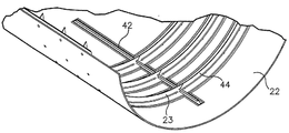
도 6a, 6b 및 도 7에 도시되는 바와 같이, 본 발명의 한 예시적인 실시예에서, 내부 스티프너(24) 및/또는 더미 내부 스티프너(23)는 해당 보강 삽입재(26)들에 의하여 적어도 두 개의 측면 상에서 지지되는 J-스티프너(42)를 포함할 수 있다. 더구나, 본 예시적인 실시예에서, 내부 스티프너(24) 및/또는 더미 내부 스티프너(23)는 실질적으로 "T"-모양의 단면적을 가진 프레임(44)을 포함할 수 있고, 상기 프레임(44)은 또한 해당 보강 삽입재(26)에 의하여 적어도 두 개의 측면에서 지지된다. 도 7에 도시되는 바와 같이, 보강 삽입재(26) 및/또는 더미 내부 스티프너(23)의 부분은 제자리에서 유지되고, 슬플라이스 스트랩(splice strap) 및 볼트와 같은 기계적 패스너(mechanical fastener, 46)에 의해 함께 유지된다. 그러나, 내부 스티프너(24) 및/또는 더미 내부 스티프너(23)는 공지된 어떠한 형상을 가질 수 있고, 보강 삽입재(26)는 그와 함께 접합될 어떠한 모양과 형상일 수 있다.6A, 6B, and 7, in one exemplary embodiment of the present invention, the
도 8에 도시되는 바와 같이, 강성 외부 도구(28)는 기체(15)의 외부 표면의 모양을 형성하기 위하여 형성되는 내부 표면을 가진 강성 도구일 수 있다. 예를 들어, 도 2 또는 도 8에 도시되는 바와 같이, 강성 외부 도구(28)는 클램 셀 도구일 수 있고, 하측 클램 셀과 상측 클램 셀을 포함하는 두 개의 반쪽을 가질 수 있다. 두 개의 반쪽은 함께 강성 외부 도구(28)의 내부 표면에 의하여 묶인 속이 빈 원통형 모양을 형성할 수 있다. 그러나, 강성 외부 도구(28)는 복수의 부분을 포함할 수 있는데, 함께 결합될 때, 기체(15)의 욉 nvyaus의 모양을 형성하기 위해 형성되는 내부 표면을 형성할 수 있다.8, the rigid
일반적으로, 기체(15)를 제작하는 방법은 내부 스티프너(24)를 위하여 SMP 장치(12)를 캐비티(40)를 가진 강성 도구 형상으로 형성하는 단계, 경화되거나 경화되지 않은 내부 스티프너(24)와 보강 삽입재(26)를 SMP 장치(12) 내의 캐비티(40) 내에 위치시키는 단계, 경화되지 않은 복합물 재료(14)를 SMP 장치(12) 상에 위치시킨 후, SMP 장치(12)와 경화되지 않은 복합물 재료(14)를 강성 외부 도구(28) 내로 위치시키는 단계를 포함한다. 그 다음의 방법은 SMP 장치(12)를 동시에 팽창 또는 아니면 확장하는 동안 압력과 열을 통하여 복합물 재료(14)를 경화시켜서 경화 공정 동안에, 강성 외부 도구(28)에 대하여 복합물 재료(14)를 압축하고, 그런 후에 복합물 재료(14)는 경화되고, SMP 장치(12)는 단면적이 감소되고, SMP 장치(12)를 결과적인 기체 내로부터 빼내는 단계를 포함한다. 이에 의해, 내부 스티프너(24)는 복합물 기체와 함께-본딩 및/또는 함께-경화되고, 기체에 내부 스티프너(24)를 부착시키기 위한 기계적 패스너의 필요성이 없어진다. 또한, 본 명세서에 기술된 내부 스티프너(24)와 기체가 함께-경화 또는 함께-본딩 방법은 기술 분야에서 알려진 임의의 복합물 부재(본 명세서에 나열된 다양한 항공기 구성)와 스티프너 또는 다른 구성과 함께-경화 또는 함께-본딩되는데 사용될 수 있다.Generally, the method of making the
도 14의 흐름도는 SMP 장치(12)를 기체(15)를 제작하는데 사용되는 강성 도구 형상으로 형성하기 위한 예시적인 방법(1400)의 단계들을 도시한다. 일부 대안적인 실시에서, 다양한 블럭으로 표시된 기능은 도 14에서 순서대로 도시되지 않을 수 있다. 예를 들어, 도 14에 순서대로 도시된 두 개의 블럭이 실제로는 거의 동시에 실행되거나, 관련된 기능에 따라 가끔은 역순으로 실행될 수 있다.The flow chart of Figure 14 shows the steps of an
방법(1400)은 도 3에 도시되는 바와 같이, 팽창된 상태인 SMP 장치(12)를 수용하는 단계 또는 블럭(1402)에 도시되는 바와 같이, 그 기억 형상인 SMP 장치(12)를 수용하고 난 후, SMP 장치(12)를 가열하고 팽창시켜서 팽창된 상태로 되는 단계를 포함한다. 또한, SMP 장치(12)의 확장은 SMP 장치(12)의 계수를 바꾸기 위한 다양한 다른 전환수단 및/또는 SMP 장치(12)를 원하는 크기로 확장하기 위한 다양한 다른 힘 또는 기술을 사용하여 얻을 수 있다. 그런 다음, SMP 장치(12)는 내부 맨드렐 도구(16) 위로 미끄러지기에 충분히 클 수 있다. 대안적으로, SMP 장치(12)는 내부 맨드렐 도구(16)에 맞춤되기 충분히 크게 기억 형상으로 주조될 수 있다. 방법(1400)의 다음 단계는, 블럭(1404)에 도시되는 바와 같이, 내부 맨드렐 도구(16)가 SMP 장치(12)로 미끄러지거나 내부 맨드렐 도구(16) 상으로 미끄러지는 것일 수 있다. 본 발명의 또 다른 대안적인 실시예에서, SMP 장치(12)는 붕괴된 상태에서 수용될 수 있고, 도 4의 내부 맨드렐 도구(16)에 이미 맞춰질 수 있다.The
블럭(1406)에 도시되는 바와 같이, SMP 장치(12)가 내부 맨드렐 도구(16) 상에 위치된 후에, 본 방법(1400)은 SMP 장치(12)를 Tg 이상으로 가열하는 단계를 포함하고, 그 온도에서 SMP 재료는 가단성이면서 형성력이 있게 된다. Tg 문턱 온도 이상에서, SMP 장치(12)는 자연히 원래의 기억 형상과 크기로 다시 수축할 수 있고, 도 5에 도시되는 바와 같이, 이는 SMP 장치(12)가 수축하여 내부 맨드렐 도구(16)를 형성할 수 있도록 한다. 또한 또는 대안적으로, 진공은 팽창 개구부를 통하여 내부 맨드렐 도구(16)내로 부터 가해질 수 있고, 내부 맨드렐 도구(16)에 대하여 가열되고 가단성인 SMP 장치(12)를 흡입할 수 있다. 본 발명의 일부 실시예에서, 내부 맨드렐 도구(16)는 마주보는 말단부(32, 34)의 각각에 모따기 또는 각진 부분(48)을 가질 수 있고, SMP 장치(12)가 그와 일치될 수 있다. 모따기되거나 각진 부분(48)을 넘어 외부 방향으로 확장되는 어떤 초과 재료는 다트되거나(darted) 잘려질 필요가 있다.After the
본 방법(1400)은, 블럭(1408)에 도시되는 바와 같이, 말단 밀봉부(18, 20)를 SMP 장치(12) 및 내부 맨드렐 도구(16)에 가하는 단계를 더 포함할 수 있고, 내부 맨드렐 도구(16)와 SMP 장치(12) 사이에 압력 베슬을 만드는 단계를 더 포함할 수 있다. 구체적으로, SMP 장치(12)가 수축되어서, SMP 장치(12)의 말단 부분은 내부 맨드렐 도구(16)를 향하여 안쪽 방향으로 가압될 수 있고 및/또는 모따기되거나 각진 부분(48)은 스웨이지 락과 같은 말단 밀봉부(18, 20)에 의하여 잠겨진다. 본 발명의 일부 실시예에서, 말단 밀봉부(18, 20)는 내부 맨드렐 도구(16)의 모따기되거나 각진 부분(48)과 접합될 수 있고, 말단 밀봉부들(18, 20)과 내부 맨드렐 도구(16) 사이의 SMP 장치(12)의 부분을 샌드위칭 하여 기밀 밀봉부를 형성할 수 있다. 본 발명의 일부 대안적인 실시예에서, 말단 밀봉부(18, 20)를 적용하는 단계는 생략될 수 있고, 또한, SMP 장치(12)는 다른 방법 또는 다른 표면에 밀봉되어 SMP 장치(12)에 작용하는 압력 차이를 가능하게 할 수 있다.The
방법(1400)의 다음 단계는, 블럭(1410)에 도시되고, 도 7에 도시된 바와 같이, 더미 내부 스티프너(23) 및/또는 보강 삽입재(26)를 더미 스킨(22) 상에, 기체 내의 내부 스티프너(24)의 원하는 지점에 대응된 형상으로 위치시키는 단계를 포함한다. 더미 스킨(22), 더미 내부 스티프너(23) 및/또는 보강 삽입재(26)는 얇은 필름 또는 어떤 다른 물질로 커버되어서, 그들이 서로 및/또는 SMP 장치(12)와 접착되는 것을 막는다. 그런 다음, 방법(1400)은, 블럭(1412)에 도시되는 바와 같이, 더미 스킨(22)을 강성 외부 도구(28) 내로 위치시키는 단계를 포함할 수 있다. 구체적으로, 더미 스킨(22)은 복합물 재료(14)의 두께에 대한 플레이스 홀더(place holder)의 역할을 하거나 이를 본뜨기 위하여, 강성 외부 도구(28)의 내부 표면에 도포될 수 있고, 상기 복합물 재료는 나중에 SMP 장치(12) 상에 위치될 것이다. 이는 원하는 두께에서, SMP 장치(12) 위에 도포된 복합물 재료(14)를 가진 SMP 장치(12)는 강성 외부 도구(28) 내에 여전히 맞춰질 것이다.The next step of
보강 삽입재(26)는 더미 내부 스티프너(23)와 함께, 강성 외부 도구(28) 상에 있는 더미 스킨(22) 상에 위치될 수 있고, 이는 경화되거나 경화되지 않은 내부 스티프너(24)의 크기와 형상을 모방하기 위하여 모형화 및 형상화될 수 있다. 더미 내부 스티프너(23)는 캐비티(40)로부터 나중에 제거될 수 있고, 경화되거나 경화되지 않은 내부 스티프너(24)로 대체될 수 있다. 보강 삽입재(26)와 함께 경화되거나 경화되지 않은 내부 스티프너(24)는 그루브 또는 캐비티(40) 내로 위치되어서 내부 스티프너(24)는 기체(15)를 제작하는 복합물 재료(14)와 함께-본딩되거나 함께-경화될 수 있다.The reinforcing
상기 기재된 바와 같이, 더미 내부 스티프너(23) 생략되거나 및/또는 본 명세서에 기술된 다른 어떤 단계로 경화되지 않거나 경화된 상태에서 내부 스티프너(24)로 대체될 수 있다. 예를 들어, 내부 스티프너(24) 및/또는 보강 삽입재는 캐비티(40)를 형성하는데 사용될 수 있다. 본 발명의 일실시예에서, SMP 장치(12)의 형성 동안에 내부 스티프너(24)는 사전-경화되거나 및/또는 경화될 수 있고, 나중에, 경화되는 동안에 복합물 재료(14)와 함께-본딩 될 수 있어서, 기체(15)를 제작할 수 있다.As described above, the dummy
본 방법(1400)은, 블럭(1414)에 도시되고 도 8에 도시되는 바와 같이, 내부 맨드렐 도구(16)와 함께 SMP 장치(12)를 강성 외부 도구(28) 내에 위치시키고, 그런 다음 블럭(1416)에 도시된 바와 같이, SMP 장치(12)를 가열하고 가압하는 단계를 더 포함할 수 있다. 가열 및 가압은 SMP 장치(12)가 팽창하여 더미 스킨(22), 더미 내부 스티프너(23), 내부 스티프너(24) 및/또는 보강 삽입재(26)에 대하여 가압하도록 한다. 상기 언급된 바와 같이, SMP 장치(12)는 SMP 장치(12)의 계수를 변화시켜서 형성력 있고 확장가능하도록 하기 위하여, Tg 까지 혹은 그 이상으로 가열될 수 있다. 그러나, 다른 방법도, 본 명세서에 기술되는 바와 같이, SMP 장치(12)의 계수를 변화시키는데 사용될 수 있다. 더구나, 본 발명의 대안적인 실시예에서, 방법 단계들(1410 - 1414)은 SMP 장치(12)를 복합물 부재의 내부 표면을 모방하기 위하여 모형화되고 형성된 임의의 강성 외부 몰드 내에 위치시키는 단계로 대체될 수 있고, 복합물 부재는 SMP 장치(12) 내로 원하는 캐비티(40)를 형성하기 위한 돌출부로 형성되고, 이를 포함한다.The
압력 또는 압력 차이는 도 4에 도시되는 바와 같이, 내부 맨드렐 도구(16)의 팽창 개구부(36)를 통하여 가압된 압축 기체를 통하는 것과 같은 복수의 방법에 의해 도입될 수 있다. 예를 들어, SMP 장치(12)를 확장시키기 위한 압력은 SMP 장치(12)의 두께 및/또는 전반적인 크기에 따라 다르다. 더구나, SMP 재료의 유형 및/또는 SMP 장치(12)의 디자인도 얼마나 쉽게 또는 얼마나 어렵게 SMP 장치(12)에 스트레인 하는지 영향을 줄 수 있다. 본 발명의 일부 실시예에서, 1-150 파운드-힘퍼 스퀘어 인치 게이지(psig) 범위의 압력 또는 30 - 90 psig 의 좁은 범위인 압력은 SMP 장치(12)를 팽창시키는데 가해질 수 있다. 예를 들어, 대략 45 psig는 SMP 장치(12) 내에 가해져서, SMP 장치(12)를 팽창시킬 수 있다. 더구나, 본 명세서에 기술되는 어떤 방법 단계에서, SMP 장치(12)가 가열되고 가압되는 곳은, 낮은 압력 차이가 열이 Tg까지 또는 그 이상으로 증가함에 따라 도입되어 합물 재료(14)가 부드러워지기 시작하여 SMP 장치(12)가 붕괴되는 것을 막는다. 그런 다음, SMP 장치(12)가 Tg를 초과한 어떤 점에서, 압력 차이는 원하는 전체 양까지 증가할 수 있다. 예를 들어, 대략 5 내지 10 psi의 낮은 압력은 충분한 열이 SMP 장치(!2)가 충분히 가단성이 되도록 가해질 때까지 SMP 장치(12)에 가해지고, 여기서 가해진 압력은 30 - 90 psi와 같은 경화 사이클 압력까지 증가될 수 있다.The pressure or pressure difference may be introduced by a plurality of methods, such as through a pressurized compressed gas through the
다음으로, 본 방법(1400)은, 블럭(1418)에 도시되는 바와 같이, 강성 도구 형상으로 SMP 장치(12)를 냉각시켜서 단단하게 하는 단계를 포함할 수 있다. 팽창 압력은 SMP 장치(12)의 온도가 Tg 이하로 냉각되는 동안 계속 가해져서, SMP 장치가 팽창된 강성 도구 형상으로 단단하게 하게 될 수 있다. 이에 의해, SMP 장치(12)는 더미 스킨(22), 더미 내부 스티프너(23), 내부 스티프너(24) 및/또는 보강 삽입재(26)에 따라 형성되고, 이는 캐비티(40) 또는 SMP 장치(12) 내로 그루브를 형성한다. 블럭(1420)에 도시된 바와 같이, 본 방법(1400)은 강성 외부 도구(28)로부터 SMP 장치(12) 및 내부 맨드렐 도구(16)를 제거하는 단계를 포함할 수 있다. 또한, 도 9에 도시된 바와 같이, 더미 스킨(22)은 SMP 장치(12)로부터 제거될 수 있다. 도 10a는 더미 내부 스티프너(23)가 제거되고, 이에 의해 방법(1400)에 의해 형성된 캐비티(40)이 나타난 후인, 강성 도구 형상인 결과적인 SMP 장치(12)를 추가로 도시한다. 도 10b는 더미 내부 스티프너(23)가 도 9에 위치되었던 곳에 위치된 내부 스티프너(24)와 함께, 강성 외부 형상인 결과적인 SMP 장치(12)를 도시하고, Next, the
도 15의 흐름도는 SMP 장치(12)를 사용하여 기체(15)를 제작하기 위한 예시적인 방법(1500)을 좀 더 자세히 나타낸다. 일부 대안적인 실시에서, 다양한 블럭으로 표시된 기능은 도 15에서 순서대로 도시되지 않을 수 있다. 예를 들어, 도 15에 순서대로 도시된 두 개의 블럭이 실제로는 거의 동시에 실행되거나, 관련된 기능에 따라 가끔은 역순으로 실행될 수 있다.The flow diagram of FIG. 15 shows in more detail an
도 15에 도시된 바와 같이, 본 방법(1500)은, 블럭 1502 및 도 14의 방법 단계에 도시되는 바와 같이, 처음에 SMP 장치(12)를 강성 도구 형상으로 형성하는 단계를 포함할 수 있다. 상기 기술된 바와 같이, 이 단계는 SMP 장치(12) 내의 캐비티(40)를 완성된 기체(15) 내의 내부 스티프너(24)의 원하는 지점에 대응하는 형상으로 형성하는 단계를 필요로 할 수 있다. 복수의 방법은 SMP 장치(12)를 캐비티(40) 또는 그루브가 형성된 원하는 강성 도구 형상으로 형성하는데 사용될 수 있다.As shown in FIG. 15, the
SMP 장치(12)가 강성 도구 형상으로 형성된 후에, 기체(15)를 제작하는 방법(1500)은, 블럭(1504)에 도시되고, 도 10b에 도시되는 바와 같이, 경화되거나 경화되지 않은 내부 스티프너(24) 및 보강 삽입재(26)를 SMP 장치(12) 내의 캐비티 내에 위치시키는 단계를 포함할 수 있다. 그러나, 본 발명의 일부 실시예에서, 가열되고, SMP 장치(12)가 강성 도구 형상으로 형성되는 동안에, 내부 스티프너(24)가 보강 삽입재(26) 상에 또는 그들 사이에 이미 위치된다면, 내부 스티프너(24)와 보강 삽입재(26)는 SMP 장치(12) 내에 만들어진 결과적인 캐비티(40) 또는 그루브 내에 남아 있을 수 있고, 단계(1504)는 생략될 수 있다.After the
본 발명의 일부 실시예에서, 내부 스티프너(24)는 SMP 장치(12)에 대하여 상기 기술된 바와 같이, 경화되지 않은 재료를 하나 이상의 스티프너 SMP 장치(SMP 재료로 제조됨)에 도포되거나 및/또는 립핑될 수 있다. 이 방법에서, 내부 스티프너(24)와 복합물 부재 또는 기체(15) 모두는 SMP 재료를 사용하여 함께-경화될 수 있다. 그러나, 스티프너 SMP 장치에 대하여 사용된 SMP 재료는 기체(15)를 형성하는데 사용되는 SMP 장치(12) 보다는 다양한 전환수단 및/또는 다양한 Tg를 가질 수 있다. 스티프너 SMP 장치 또는 기체(15)에 대한 SMP 장치(12)의 방법은 함께-경화되는 동안에 강성을 유지하는 반면, 스티프너 SMP 장치의 다른 것과 SMP 장치(12)는 함께-경화되는 동안에 내부 블래더로서 사용된다.In some embodiments of the present invention, the
그런 다음, 방법(1500)은 블럭(1506)에 도시되고, 도 11에 도시된 바와 같이, 경화되지 않은 복합물 재료(14)를 SMP 장치(12) 상에 도포하는 단계를 포함할 수 있다. 구체적으로, 복합물 재료(14)는 SMP 장치(12) 및 캐비티(40) 내에 있는 내부 스티프너(24) 상에 도포될 수 있어서, 본 명세서에서 나중에 기술되는 바와 같이, 내부 스티프너(24)의 적어도 부분은 접촉하고, 기체(15)의 복합물 재료(14)에 함께-경화되거나 함께-본딩될 수 있다. 경화되지 않은 복합물 재료(14)는 자동화된 직물 장치, 자동화된 섬유 장치, 자동화된 필라멘트 와인딩법 및/또는 핸드 레이-업과 같은 기술 분야에서 공지된 어떤 방법을 사용하여 SMP 장치(12) 상에 위치될 수 있다. 상기 언급된 바와 같이, 복합물 재료(14)는 저온 수지, 고온 수지, 강화된 수지, 프리프레그, 습식 처리된 섬유, 건식 섬유, 연속 섬유, 불연속 섬유, 차핑드 섬유, 유리. KEVLAR, 탄소 및/또는 코어의 형태 또는 이를 포함할 수 있다. 본 발명의 일부 실시예에서, 배리어 및/또는 이형제(release agent)가 SMP 장치(12)와 복합물 재료(14) 사이에 위치될 수 있어서, 복합물 재료(14)의 경화 후에 좀 더 용이하게 분리될 수 있도록 한다. 배리어 또는 이형제는 필름, 플라스틱 등일 수 있다. 또한, 배리어 또는 이형제는 부착면과 탈착면을 가질 수 있다.The
그런 다음, 기체(15)를 제작하는 방법(1500)은, 블럭(1508)에 도시되는 바와 같이, SMP 장치(12)와 경화되지 않은 복합물 재료(14)를 강성 외부 도구(28) 내에 위치시키는 단계를 포함할 수 있다. 그 다음에, 본 방법은, 블럭(1510)에 도시되는 바와 같이, 압력과 열을 통하여 복합물 재료(14)를 경화시키는 단계를 포함할 수 있고, 블럭(1512)에 도시되는 바와 같이, 경화 공정 동안에 이와 동시에 SMP 장치(12)를 팽창시켜서 복합물 재료(14)를 가압하는 단계를 포함할 수 있다. 본 발명의 일부 실시예에서, 팽장 압력은 내부 맨드렐 도구(16)를 통하여 제공될 수 있고, 열은 Tg 이상의 복합재 경화 온도까지 상승될 수 있다. SMP 장치(12)의 팽창은 경화 사이클 동안에 복합물 재료(14)를 압축할 수 있고, SMP 장치(12)와 강성 외부 도구(28) 사이의 경화되거나 경화되지 않은 내부 스티프너(24)를 압축할 수 있다. 또한 또는 대안적으로, SMP 장치(12)의 팽창은 하나 이상의 보강 삽입재(26)에 직접 압력을 가하여, 보강 삽입재(26)는 보강 삽입재(26) 들 사이에 위치된 내부 스티프너(24)의 부분에 직접 압력을 가한다. 또한, SMP 장치(12)의 팽창은 경화되거나 경화되지 않은 내부 스티프너(24)를 기체의 복합물 재료(14)로 압축하여, 기체에 내부 스티프너(24)를 함께-본딩 또는 함께-경화될 수 있다.The
본 발명의 또 다른 실시예에서, 밀봉부는 기계적 밀봉부, 접착제 또는 강성 외부 도구(28)에 SMP 장치(12)의 주변부분을 밀봉하기 위한 어떤 공지된 방법을 사용하여 강성 외부 도구(28)와 SMP 장치(12) 사이에서 형성될 수 있다. 강성 외부 도구(28)는 복합물 재료(14)의 경화 동안에 오토클래브에 의하여 만들어진 압력 차이를 더욱 증가시키기 위하여 배출될 수 있다. 이는 내부 멘드렐 도구(16)과의 기밀 밀봉부에 대하여 필요하지 않도록 할 수 있다. 복합물 재료(14)에 대한 SMP 장치(12)를 압축하는 다른 방법은 본 발명의 범위에서 벗어남 없이 사용될 수 있다는 것을 주목한다. 더구나, 본 명세서에 기술된 열과 압력 차이는 오토플래브(미도시) 또는 복합물 부재를 제작하기 위한 공지된 가열 및 압력 기술의 다른 조합에 의하여 제공될 수 있다.In yet another embodiment of the present invention, the seal may comprise a rigid
복합물 재료(14)가 경화된 후에, 본 방법(1500)은, 블럭(1514)에 도시되는 바와 같이, SMP 장치(12) 내로부터 팽창 압력을 제거하는 단계를 포함할 수 있고, 블럭(1516)에 도시되는 바와 같이, 결과적인 기체의 내로부터 SMP 장치(12)를 빼내는 단계를 포함할 수 있다. 압력이 제거된 후에, 열이 Tg 이상으로 유지되는 동안 SMP 장치(12)는 내부 맨드렐 도구(16) 주위에 접촉할 수 있다. 예를 들어, 진공이 내부 맨드렐 도구(16) 내로부터 가해져서, 내부 맨드렐 도구(16)에 대하여 다시 SMP 장치(12)를 흡입할 수 있다. 도 12에 도시된 바와 같이, SMP 장치(12)는 이에 의해 경화된 복합물 재료(14)로부터 빼낼 수 있다. 이에 따라, 내부 맨드렐 도구(16)를 경화된 기체 내로부터 빼내서, 내부 스티프너(24)는 SMP 장치(12)의 빼내는 것을 야기하고, 이는 팽창 압력이 제거된 후에 내부 맨드렐 도구(16)에 대하여 접촉한다.After the
마지막으로, 본 방법(1500)은 블럭(1518)에 도시되는 바와 같이, 경화된 내부 스티프너(24)로부터 보강 삽입재(26)를 제거하는 단계를 포함할 수 있고, 블럭(1520)에 도시되는 바와 같이, 강성 외부 도구(28)로부터 기체를 빼내는 단계를 포함할 수 있다. 예를 들어, 강성 외부 도구(28)의 부분은 서로 기계적을 분리될 수 있어서, 기체(15)와 그 통합된 내부 스티프너(24)는 강성 외부 도구(28)로부터 들어올려지도록 한다.Finally, the
본 발명의 대안적인 실시예에서, SMP 장치(12)는 경화되는 동안에 강성을 유지할 수 있다. 예를 들어, 경화되지 않은 복합물 재료(14)가 SMP 장치(12) 위에 도포된 후에, 이들은 진공백이 되거나 가요성이고 불침투성 재료(미도시) 내의 밀봉되고 경화될 수 있다. 이 대안적인 실시예에서, 복합물 재료(14)의 경화 온도는 SMP 장치(12)이 가단성이 되기 시작하는 온도 Tg 미만일 수 있고, SMP 장치(12)는 경화 사이클 동안 강성을 유지한다. 그래서, 경화되는 동안 블래더로서 SMP 장치(12)를 사용하는 대신, SMP 장치(12)는 기체의 복합물 재료(14)와 내부 스티프너(24)의 함께-경화 또는 함께 본딩되는데 사용되는 진공백 또는 불침투성 재료의 압축력과 함께 경화되는 동안 강성을 유지할 수 있다. 그리고 나서, 복합물 재료(14)가 경화된 후에, 진공백은 결과적인 기체 주위로부터 제거될 수 있고, SMP 장치(12)의 온도는 Tg 이상으로 상승하여, SMP 장치(12)는 가다성 및/또는 기체 내로부터 제거될 기억 형상과 접촉할 수 있다.
In an alternative embodiment of the present invention, the
SMPSMP 장치를 가진 With a device 스티프너Stiffener 제작 making
도 16 - 17에 가장 잘 도시되는 바와 같이, 본 발명의 또 다른 실시예는 내부 스티프너(24), 상기 기술된 프레임 및/또는 스트링거와 같은 스티프너(50)를 제작하는 방법이다. 본 발명의 이 실시예에서, 본 방법은, 도 16에 도시되는 바와 같이, SMP 장치(12), 강성 몰딩 도구(rigid molding tool, 52) 및 진공백과 같은 불침투성 재료의 시트(54)를 사용하여 스티프너를 제작하는데 실시될 수 있다.As best shown in Figures 16-17, another embodiment of the present invention is a method of making a
도 16에 도시된 SMP 장치(12)는 도 1 - 2에 도시된 발명의 실시예에 대하여 기술된 SMP 장치(12)와 같은 동일한 장점 및 특징을 가질 수 있다. 더구나, SMP 장치(12)는 상기 기술된 방법과 같은 원하는 방법을 사용하여 원하는 강성 도구 형상으로 형성될 수 있다. 본 발명의 일부 실시예에서, SMP 장치(12)는 결과적인 스티프너(50)의 적어도 하나의 표면의 원하는 모양 또는 윤곽과 실질적으로 일치하는 기억 형상으로 주조될 수 있다. 예를 들어, 제작될 스티프너(50)가 사다리꼴 단면적을 가진 스트링거라면, SMP 장치(12)는 거의 사다리꼴 단면적을 가진 기억 형상으로 주조될 수 있다. 대안적으로, SMP 장치(12)는 길쭉한 모양으로 주조될 수 있고, 삽입된 것은 속이 빈 몰드, 가열된 후 팽창될 수 있으며, 속이 빈 몰드에 의해 제공된 모양으로 냉각되고 단단해 질 수 있다.The
강성 몰딜 도구(52)는 상기 기술된 강성 외부 도구(28)와 기능과 디자인 면에서 유사 또는 동일할 수 있고, 복합물 재료가 경화되는 동안에 강성으로 유지할 수 있는 강철과 같은 재료로 제조될 수 있다. 대안적으로, 강성 몰딩 도구(52)는 복합물 재료(14)가 경화되는 동안에 강성으로 유지하도록 형성된 SMP 재료로 제조될 수 있다. 예를 들어, 강성 몰딩 도구(52)는 도 10a에 도시된 SMP 장치(12)일 수 있고, 도 16에 도시된 SMP 장치(12)의 Tg는 본 발명의 대안적인 실시예에서, 강성 몰딩 도구(52)의 Tg와 상이할 수 있다. 강성 몰딩 도구(52)는 적어도 하나의 원하는 스티프너의 외부 표면을 형성하기 위하여 형성될 수 있다. 예를 들어, 강성 몰딩 도구(52)는 그 안에 형성된 캐비티(56)를 포함할 수 있고, 경화되지 않은 복합물 재료(14)가 그 곳에 위치되어, 스티프너(50)의 적어도 하나의 벽을 형성할 수 있다. 도 16에 도시되는 바와 같이, 캐비티(56)는 바닥부(bottom)를 통할 수 있고, 두 측벽은 바닥부로부터 90도가 아닌 각도일 수 있다.The
불침투성 재료의 시트(54)는 진공백 또는 다른 가요성이며 불침투성 재료일 수 있고, 이는 강성 몰딩 도구(52) 및/또는 SMP 장치(12)를 밀봉할 수 있다. 예를 들어, 불침투성 재료의 시트(54)는 복합물 재료(14) 상에 위치되고, 강성 몰딩 도구(52)에 밀봉되며, 불침투성 재료의 시트(54)와 강성 몰딩 도구(52) 사이에 실질적으로 기밀 밀봉부를 형성할 수 있다. 또한, 불침투성 재료의 시트(54)는 공기를 흡입하고 배출하도록 하기 위하여 연장된 진공 포트(미도시)를 포함할 수 있다. 공기가 강성 몰딩 도구(52)와 불침투성 재료의 시트(54) 사이로부터 제거될 때, 불침투성 재료의 시트(54)는 그 사이에 위치된 복합물 재료(14)를 압축할 수 있다. 또는 또한 대안적으로, SMP 장치(12)는 오토클래브 및/또는 압축 기체에 의하여 압축될 수 있고, 그런 다음 SMP 장치(12)를 강성 몰딩 도구(52) 및 불침투성 재료의 시트(54)로 팽창한다. 더구나, 카울 시트(caul sheet)(미도시)는 불침투성 재료의 시트(54)와 복합물 재료(14) 사이에 위치되어 복합물 재료(14)의 완성된 윤곽과 표면을 더 잘 제어할 수 있다. 또한, 기술 분야에서 공지된 다른 복합물 배깅 기술은 본 발명의 범위에서 벗어남 없이 본 명세서에서 사용될 수 있다.The sheet of
본 발명의 대안적인 실시예에서, 불침투성 재료의 시트(54)는 복합물 재료(14)와 SMP 장치(!2) 위에 위치될 수 있는 침투성 재료의 시트로 대체될 수 있다. 본 발명의 이 실시예에서, 경화시 SMP 장치(12)가 복합물 재료(14)를 압축하는 동안에, 침투성 재료의 시트는 물리적으로 복합물 재료(14)를 가압할 수 있다. 본 발명의 또 다른 대안적인 실시예에서, 불침투성 재료의 시트(54)는 침투성 또는 불침투성일 수 있는 강성 커퍼링 도구(rigid covering tool)로 대체될 수 있고, 클램핑되거나, 가압되거나 혹은 기계적으로 강성 몰딩 도구(52)에 및 복합물 재료(14) 상에 고정될 수 있다.In an alternative embodiment of the present invention, the sheet of
도 17의 흐름도는 SMP 장치(12)를 사용하여 복합물 스티프너를 제작하기 위한 예시적인 방법(1700)의 단계들을 도시한다. 일부 대안적인 실시에서, 다양한 블럭으로 표시된 기능은 도 17에서 순서대로 도시되지 않을 수 있다. 예를 들어, 도 17에 순서대로 도시된 두 개의 블럭이 실제로는 거의 동시에 실행되거나, 관련된 기능에 따라 가끔은 역순으로 실행될 수 있다.The flow chart of FIG. 17 shows the steps of an
SMP 장치(12)를 사용하여 스티프너(50)를 제작하는 방법(1700)은, 블럭(1702)에 도시되는 바와 같이, SMP 장치(12)를 강성 도구 형상으로 형성하는 단계를 포함하고, 그런 다음, 블럭(1704)에 도시되는 바와 같이 복합물 재료(14)를 SMP 장치(12)의 적어도 일부에 도포하는 단계를 포함할 수 있다. 본 발명의 일부 실시예에서, SMP 장치(12)의 강성 도구 형상은 그 위에서 형성될 스티프너(50)의 내부 모양 및/또는 각도와 일치할 수 있다. 본 발명의 다른 실시예에서, 재료(14)는 우선 SMP 장치(12) 상에 위치되거나 랩핑될 수 있고, 그런 다음 SMP 장치(12)는 기술 분야에 공지되거나 본 명세서에 기술된 어떠한 몰딩 기술을 사용하여 강성 도구 형상으로 형성될 수 있다.The
그런 다음, 본 발명(1700)은, 블럭(1706)에 도시되는 바와 같이, 복합물 재료(14)로 도포된 SMP 장치(12)를 강성 몰딩 도구(52)의 캐비티(56) 내에 위치시키는 단계를 포함할 수 있다. 대안적으로, 복합물 재료(14)는 강성 몰딩 도구(52)의 캐비티(56) 내에 놓인 다음 강성 도구 형상인 SMP 장치(12)가 강성 몰딩 도구(52)의 캐비티(56) 내의 복합물 재료(14) 상에 위치시킬 수 있다.The
그러나, 본 발명의 범위에서 벗어남 없이, 복합물 재료(14)를 SMP 장치(12)와 접촉하도록고, 강성 몰딩 도구(52)의 캐비티 내에 위치시킬 수 있는 많은 기술이 사용될 수 있다. 더구나, 본 발명의 일부 실시예에서, 복수의 SMP 장치가 스티프너(50)를 제작하는데 사용될 수 있다. 예를 드어, 도 16에 도시되는 바와 같이, SMP 장치(12)의 특성(상기에서 기술되는 바와 같이)을 가진 두 개의 SMP 장치(58, 60)는 복합물 재료(14)의 마주보는 표면을 지지하기 위하여 모형화 또는 몰딩되어 스티프너(50)를 J-스트링거 형상으로 제작한다. 구체적으로, 스티프너(50)는 거의 J-모양의 단면을 가진 길쭉한 스티프너일 수 있다. 복합물 재료(14)는, 도 16에 도시되는 바와 같이, 핸드 레이-업 또는 기술 분야에서 공지된 다른 방법을 사용하여, 두 개의 SMP 장치(58, 60)와 강성 몰딩 도구(52) 사이에 위치될 수 있다. 그런 다음, 스킨 라미네이트(skin laminate, 62)는 두 개의 SMP 장치(58, 60) 위에 위치되어, 스티프너(50)의 J-모양의 단면을 제작하는 복합물 재료(14)의 상부 말단과 접촉할 수 있다. 본 발명의 이 실시예에서, 스킨 라미네이트(62)와 복합물 재료(14)는, 본 명세서에서 나중에 기술되는 바와 같이, 함께-본딩 될 수 있다.However, many techniques can be used to place the
따라서, 일반적으로 본 방법(1700)은 또 다른 복합물 재료의 층 또는 스킨 라미네이트(62)를 SMP 장치(12) 위에 위치시켜서, 블럭(1708)에 도시되는 바와 같이, 강성 몰딩 도구(52)의 캐비티(56) 내에 있는 복합물 재료(14)의 적어도 일부와 접촉시키는 단계를 포함할 수 있다. 그 다음, 본 방법은, 블럭(1710)에 도시되는 바와 같이, 불침투성 재료의 시트(54)를 복합물 재료(14) 및/또는 스킨 라미네이트(62) 위에 위치시키고, 블럭(1712)에 도시되는 바와 같이, 강성 몰딩 도구(52)에 대하여 불침투성 재료의 시트(54)를 밀봉하고, 이에 의하여 복합물 재료(14)의 주위에 기밀 경계부를 형성할 수 있다. 또한, 기밀 경계부는 SMP 장치(12)에 대하여 적어도 하나의 배출 개구부(미도시)를 남겨두고, SMP 장치 위에 및/또는 그에 대하여 형성되어서, SMP 장치(12) 내의 공간이 기밀 경계부의 대기 외부 방향으로 노출되도록 할 수 있다.Thus, generally, the
그런 다음, 본 방법(1700)은, 블럭(1714)에 도시되는 바와 같이, 불침투성 재료의 시트(54)를 강성 몰딩 도구(52)로 향하도록 하는 압력 차이를 유발하는 단계를 포함할 수 있다. 예를 들어, 이 단계는 불침투성 재료의 시트(54)와 강성 몰딩 도구(52) 사이로부터 진공기에 의하여 공기를 제거하고, 이는 불침투성 재료의 시트(54)를 복합물 재료(14) 및/또는 스킨 라미네이트(62)를 향하여 또는 그에 대하여 가압할 수 있다. 블럭(1714)에 도시되는 단계 이후 또는 그와 동시에, 본 방법(1700)은 블럭(1716)에 도시되는 바와 같이, 복합물 재료(14)와 SMP 장치(12)를 복합물 재료(14)를 경화하기 위한 온도까지 가열하는 단계를 포함할 수 있다. 복합물 경화 온도는 Tg보다 클 수 있어서, SMP 장치(12)가 가단성이 되고, 외부 방향으로 밀치거나 팽창되고, 복합물 재료(14)에 대하여 가압할 수 있다. 그래서, SMP 장치(12)는 내부 진공백과 유사한 행동을 할 수 있고, 또한 또는 대안적으로, 기체 또는 공기 압력은 SMP 장치 내로 도입되어 복합물 재료(14)를 가압하기 위하여 그 팽창을 야기 또는 도와줄 수 있다.The
본 발명의 일부 대안적인 실시예에서, 적어도 하나의 SMP 장치(58, 60)는 동일한 모양의 강성 도구로 대체될 수 있다. 본 발명의 다른 대안적인 실시예에서, SMP 장치(58, 60)는 동일한 모양의 강성 도구로 대체될 수 있고, 강성 몰딩 도구(52)는 도 10a의 SMP 장치(12)로 대체될 수 있다. 일반적으로, SMP 장치와 강성 몰딩 도구의 임의의 조합은 본 명세서에 기술된 복합물 부재를 형성하는데 사용될 수 있다.In some alternative embodiments of the present invention, the at least one
복합물 재료(14)가 경화된 후에, 본 방법은, 블럭(1718)에 도시되는 바와 같이, 강성 몰딩 도구(52)로부터 불침투성 재료의 시트(54)를 제거하는 단계를 포함할 수 있다. 본 발명의 일부 실시예에서, 본 방법(1700)은 또한, 블럭(1720)에 도시되는 바와 같이, SMP 장치(12)에 계속 가열 또는 재가열을 하여, SMP 장치(12)가 수축되거나 아니면 경화된 스티프너(50)로부터 떨어지도록 할 수 있다. 기체 또는 공기 압력이 SMP 장치(12)의 팽창을 도와준다면, 이 압력도 제거될 수 있다. SMP 장치(12)는 원래의 기억 형상으로 다시 자연스럽게 수축될 수 있고, 냉각되기 전까지 부드럽고 가단성이 유지될 수 있다. 따라서, 본 방법(1700)은, 블럭(1722)에 도시되는 바와 같이, 그 부드럽고 가단성인 상태인 동안 경화된 복합물 재료(14) 또는 스티프너(50)로부터 SMP 장치(12)를 제거하는 단계를 포함할 수 있다. 대안적으로, SMP 장치(12)는 가단성 상태인 동안, 수축되거나 경화된 스티프너(50)로부터 떨어질 수 있으나, 경화된 스티프너(50)로부터 제거되기 전에 냉각되거 단단해 진다.After the
경화된 스티프너(50)로부터 일단 제거되면, SMP 장치(12)는 SMP 장치(12)의 스트레인 제한 내에서 원하는 강성 도구 형상으로 재형성될 수 있고, 또 다른 스티프너로 재사용될 수 있다는 것을 주목한다. 일반적으로, SMP 장치(12)는 재형성 및 재사용될 수 있다. 역으로, 기술 분야의 내부 맨드렐 백은 재사용되지 못하거나, 원하는 내구성을 제공하지 못하여 오류가 나기 쉽다. 또한, 내부 맨드렐 백은 그 위에 복합물 재료(14)를 도포하기 위하여 레이-업 도구로서 사용되는 강성도가 필요하지 않다. 구체적으로, 종래의 도포 형성-스티프너에서 사용되는 맨드렐의 다른 유형은 경화된 스티프너를 잘라내거나 씻어내야 할 필요가 종종 있고, 그래서 또한 재사용을 할 수 없다. 바람직하게는, SMP 장치(12)는 복합물 재료 레이-업에 대한 강성 레이-업 도구와 복합물 재료(14)가 경화되는 동안 내부 백 도는 블래더로서사용될 수 있고, 복수의 사이클 동안 제거되고 재사용될 수 있다.Note that once removed from the hardened
본 발명이 첨부된 도면에서 도시된 바람직한 실시예를 참조하여 기술되었지만, 청구항에 인용된 바와 같이, 본 발명의 범위에서 벗어남 없이, 등가사항이 사용될 수 있고, 치환도 이루어질 수 있다는 것을 주목한다. 예를 들어, SMP 장치(12)의 내부 또는 외부 방향으로 가해진 진공력 또는 팽창력의 예는, 본 명에서에서 기술되는 바와 같이, 단순히 예에 불과하고, SMP 장치(12)를 원하는 몰드 및/또는 복합물 재료(12)로 향하도록 할 수 있는 압력 차이를 형성하기 위하여 기술 분야에서의 임의의 기술로 대체될 수 있다. 또한, 다양한 모양, 형상 및 툴링(tooling)은 SMP 장치(12)를 원하는 강성 도구 형상으로 모형화하기 위하여 본 명세서에 기술되는 반면, 어떠한 몰드 또는 몰드와 강성 툴링의 조합은 하나 이상의 본 명에서에서 기술된 방법 단계를 사용하여 SMP 장치(12)의 모양을 정의하는데 사용될 수 있다는 것을 주목한다. Although the present invention has been described with reference to preferred embodiments shown in the accompanying drawings, it is noted that equivalents may be used and substitutions may be made without departing from the scope of the present invention, as recited in the claims. For example, examples of vacuum forces or forces exerted in the interior or exterior direction of the
더구나, 본 명세서에서 제공된 도면과 예시적인 실시예는 항공기를 위한 복합물 부재를 제작하는 것을 기술함에도 불구하고, 본 명세서에서 기술된 도구 및 방법을 형성하는 것은 자동차, 보트, 스포츠 물품 및 본 발명의 범위에서 벗어남 없는 것 등 위한 복합물 부재를 제작하는데 사용될 수 있다.Furthermore, although the drawings and exemplary embodiments provided herein describe making composite members for an aircraft, it is contemplated that forming the tools and methods described herein may be advantageous in the manufacture of automobiles, boats, And can be used to fabricate a composite member for example.
이에 따라, 본 발명의 다양한 실시예를 가지므로, 다음을 포함하는 기재된 특허에 의하여 보호될 새롭고 원하는 바와 같이 청구된다.Accordingly, having various embodiments of the present invention, it is claimed as new and desired to be protected by the described patents including the following.
Claims (39)
형상 기억 고분자(SMP) 장치를 가단성 상태로 전환하는 단계;
하나 이상의 캐비티가 형성되고, 그 안에 스티프너가 위치되어 제작될 복합물 부재의 제1 표면의 원하는 형상과 일치하도록 SMP 장치를 가단성 상태에서 모형화하는 단계;
SMP 장치를 강성 상태로 전환하는 단계;
스티프너를 캐비티에 위치시키는 단계;
복합물 재료를 SMP 장치 및 캐비티 내에 있는 스티프너의 노출된 표면 위에 도포하는 단계; 및
복합물 부재를 제조하기 위하여 압력과 열을 통하여 SMP 장치 상의 복합물 재료로 스티프너를 함께-경화 또는 함께-본딩하는 단계를 포함하여 구성되고;
상기 복합물 재료로 스티프너를 함께-경화 또는 함께-본딩하는 단계는,
복합물 재료를 복합물 재료 경화 온도로 가열하는 단계;
강성 상태로부터 가단성 상태까지 SMP 장치의 계수의 변화를 일으키는 단계; 및
가단성 상태에서, 복합물 부재의 제2 표면의 원하는 형상과 일치하는 몰드 표면을 향하여 SMP 장치를 구동하기에 충분한 압력 차이를 도입시키는 단계 - 이에 의해 경화되는 동안 복합물 재료를 몰드 표면에 대하여 가압하고, 경화되는 동안 스티프너를 복합물 재료 내로 가압하여서, 내부 스티프너를 복합물 재료에 함께-경화 또는 함께-본딩됨 - 를 포함하는 것을 특징으로 하는 통합된 스티프너를 가진 복합물 부재를 제작하는 방법.A method of making a composite member having an integrated stiffener, the method comprising:
Converting the shape memory polymer (SMP) device to a malleable state;
Modeling the SMP apparatus in a malleable state such that one or more cavities are formed and a stiffener is positioned therein to match a desired shape of a first surface of a composite member to be fabricated;
Converting the SMP device to a stiff state;
Positioning the stiffener in the cavity;
Applying the composite material onto the exposed surface of the stiffener in the SMP device and cavity; And
Curing or joint-bonding the stiffener to the composite material on the SMP device through pressure and heat to produce a composite member;
The step of co-curing or joint-bonding the stiffener to the composite material comprises:
Heating the composite material to a composite material curing temperature;
Causing a change in the coefficient of the SMP device from the stiffness state to the malfunctioning state; And
Introducing a pressure differential sufficient to drive the SMP device towards the mold surface in conformity with the desired shape of the second surface of the composite member in the malleable state thereby compressing the composite material against the mold surface during curing, Wherein the inner stiffener is co-cured or joint-bonded to the composite material by pressing the stiffener into the composite material while the inner stiffener is bonded to the composite material.
복합물 재료 주위에 불침투성 재료의 시트를 밀봉하는 단계;
불침투성 재료의 시트의 외부 및/또는 내부 방향으로 압력 차이를 도입시킴에 의하여 복합물 재료에 대하여 불침투성 재료의 시트를 가압하는 단계; 및
복합물 재료를 복합물 경화 온도로 가열하는 단계를 포함하는 것을 특징으로 하는 통합된 스티프너를 가진 복합물 부재를 제작하는 방법.The method of claim 1, wherein the step of co-curing or co-bonding the stiffener to the composite material comprises:
Sealing the sheet of impermeable material around the composite material;
Pressurizing a sheet of impermeable material relative to the composite material by introducing a pressure differential in the outer and / or inward direction of the sheet of impermeable material; And
And heating the composite material to a composite cure temperature. ≪ Desc / Clms Page number 19 >
SMP 장치를 복합물 부재 내로부터 제거하는 단계를 포함하는 것을 특징으로 하는 통합된 스티프너를 가진 복합물 부재를 제작하는 방법.2. The method of claim 1, further comprising: uniformizing the introduced pressure differential after introducing sufficient pressure differential to cause the composite material to cure or to leave the SMP device away from the cured composite material; And
Removing the SMP device from within the composite member. ≪ RTI ID = 0.0 > 11. < / RTI >
SMP 장치를 내부 맨드렐 도구 위에 위치시키는 단계;
SMP 장치의 말단을 내부 맨드렐 도구에 밀봉시키는 단계;
SMP 장치와 내부 맨드렐 도구를 외부 몰드 내로 위치시키는 단계;
SMP 장치를 Tg이상으로 가열하여 SMP 장치를 외부 몰드를 향하여 팽창시키는 단계;
SMP 장치를 Tg 이하로 냉각시키는 단계; 및
SMP 장치를 그 강성 상태에서 외부 맨드렐 도구로부터 제거하는 단계를 포함하는 것을 특징으로 하는 통합된 스티프너를 가진 복합물 부재를 제작하는 방법.15. The method of claim 14, wherein forming the SMP device coinciding with the first surface of the composite member to be formed comprises:
Placing an SMP device on an internal mandrel tool;
Sealing an end of the SMP device to an inner mandrel tool;
Positioning the SMP device and the inner mandrel tool into the outer mold;
Heating the SMP apparatus to above Tg to expand the SMP apparatus toward the outer mold;
Cooling the SMP apparatus to below Tg; And
And removing the SMP device from the external mandrel tool in its stiffness state.
하나 이상의 캐비티가 형성되고, 그 안에 스티프너가 위치되어 제작될 복합물 부재의 제1 표면의 원하는 형상과 일치하도록 형상 기억 고분자(SMP) 장치를 형성하는 단계;
SMP 장치의 채널 또는 캐비티 내에 내부 스티프너를 위치시키는 단계;
SMP 장치가 강성 상태인 동안에, SMP 장치 및 내부 스티프너의 노출된 표면 위에 복합물 재료를 도포하는 단계;
복합물 재료를 복합물 재료 경화 온도로 가열하는 단계;
강성 상태로부터 가단성 상태까지 SMP 장치의 계수의 변화가 수행되게 하는 단계; 및
가단성 상태에서, 복합물 부재의 제2 표면의 원하는 모양과 일치하는 몰드 표면을 향하여 SMP 장치를 구동하기에 충분한 압력 차이를 도입시키는 단계 - 이에 의해 경화되는 동안 복합물 재료를 몰드 표면에 대하여 가압하고, 경화되는 동안 내부 스티프너를 복합물 재료 내로 가압하여서, 내부 스티프너를 복합물 재료에 함께-경화 또는 함께-본딩됨 - 를 포함하여 구성되고,
상기 SMP 장치는 온도 Tg이상 가열될 경우에, 가단성으로 변화되기 시작하도록 형성되고, 복합물 재료 경화 온도는 Tg 이상이어서, 복합물 재료를 복합물 재료 경화 온도로 가열하는 것은 SMP 장치의 계수가 강성 상태에서 가단성 상태까지의 변화를 수행하는 것과 동시에 수행되고,
형성될 복합물 부재의 제1 표면과 일치하는 SMP 장치를 형성하는 단계는,
SMP 장치를 내부 맨드렐 도구 위에 위치시키는 단계;
SMP 장치의 말단을 내부 맨드렐 도구에 밀봉시키는 단계;
SMP 장치와 내부 맨드렐 도구를 외부 몰드 내로 위치시키는 단계;
SMP 장치를 Tg이상으로 가열하여 SMP 장치를 외부 몰드를 향하여 팽창시키는 단계;
SMP 장치를 Tg 이하로 냉각시키는 단계; 및
SMP 장치를 그 강성 상태에서 외부 맨드렐 도구로부터 제거하는 단계를 포함하는 것을 특징으로 하는 통합된 스티프너를 가진 복합물 부재를 제작하는 방법.A method of making a composite member, the method comprising:
Forming a shape memory polymer (SMP) device such that one or more cavities are formed in which the stiffener is located to conform to a desired shape of the first surface of the composite member to be fabricated;
Placing an internal stiffener in a channel or cavity of the SMP device;
Applying the composite material over the exposed surface of the SMP device and the internal stiffener while the SMP device is in a stiff state;
Heating the composite material to a composite material curing temperature;
Causing a change in the coefficient of the SMP device to be performed from the stiffness state to the malleable state; And
Introducing a pressure differential sufficient to drive the SMP device towards the mold surface in conformity with the desired shape of the second surface of the composite member in the malleable state, thereby pressing the composite material against the mold surface during curing, Wherein the internal stiffener is pressed into the composite material and the internal stiffener is cemented or bonded together to the composite material,
The SMP apparatus is formed to start changing to malleability when heated to a temperature Tg or more, and the composite material curing temperature is higher than Tg, so that heating the composite material to the composite material curing temperature is advantageous in that the coefficient of the SMP apparatus is malleable State, < / RTI >
Forming an SMP device coinciding with a first surface of the composite member to be formed,
Placing an SMP device on an internal mandrel tool;
Sealing an end of the SMP device to an inner mandrel tool;
Positioning the SMP device and the inner mandrel tool into the outer mold;
Heating the SMP apparatus to above Tg to expand the SMP apparatus toward the outer mold;
Cooling the SMP apparatus to below Tg; And
And removing the SMP device from the external mandrel tool in its stiffness state.
SMP 장치를 복합물 부재 내로부터 제거하는 단계를 포함하는 것을 특징으로 하는 복합물 부재를 제작하는 방법.18. The method of claim 17, further comprising: uniformizing the introduced pressure differential after introducing sufficient pressure differential to cause the composite material to cure or allow the SMP device to separate from the cured composite material; And
And removing the SMP device from within the composite member.
외부 맨드렐 도구 내에 있는 더미 스킨 상에 원하는 형상인 사전-경화된 내부 스티프너를 위치시키는 단계;
외부 맨드렐 도구 내에 형상 기억 고분자(SMP) 장치를 삽입하는 단계;
SMP 장치가 가단성이 되기 시작하는 온도 Tg로 SMP 장치를 가열하는 단계;
SMP 장치를 내부 스티프너와 더미 스킨을 향하여 외부 방향으로 팽창시키는 단계 - 이에 의하여, 내부 스티프너와 일치하는 SMP 장치 내에 캐비티를 형성함 - ;
SMP 장치를 Tg 이하로 냉각시키는 단계;
외부 맨드렐 도구와 더미 스킨으로부터 SMP 장치를 제거하는 단계;
경화되지 않은 복합물 재료를 SMP 장치와 SMP 장치 내에 형성된 캐비티 내에 배치되고 사전-경화된 내부 스티프너의 노출된 표면 위에 도포하는 단계; 및
복합물 부재를 제작하기 위하여 열과 압력을 사용하여 복합물 재료로 내부 스티프너를 함께-본딩하는 단계를 포함하여 구성되고,
상기 복합물 재료로 내부 스티프너를 함께-본딩하는 단계는,
복합물 재료, 내부 스티프너 및 SMP 장치를 더미 스킨 없는 외부 맨드렐 도구 내로 다시 삽입하는 단계;
복합물 재료와 SMP 장치를 SMP Tg보다 큰 복합물 재료 경화 온도로 가열하는 단계;
SMP 장치를 팽창시키기 위하여 압력을 가하는 단계 - 이에 의해 외부 맨드렐 도구와 SMP 장치 사이에 복합물 재료와 내부 스티프너를 함께 가압함 - ;
복합물 재료가 복합물 부재 내로 경화된 후에 SMP 장치를 붕괴시키거나 수축시키는 단계; 및
복합물 부재로부터 SMP 장치를 제거하는 단계를 포함하는 것을 특징으로 하는 복합물 부재를 제작하는 방법.A method of making a composite member, the method comprising:
Placing a pre-cured internal stiffener that is the desired shape on a dummy skin within an outer mandrel tool;
Inserting a shape memory polymer (SMP) device into the outer mandrel tool;
Heating the SMP apparatus to a temperature Tg at which the SMP apparatus begins to become malleable;
Expanding the SMP device outwardly toward the inner stiffener and the dummy skin thereby forming a cavity in the SMP device coincident with the inner stiffener;
Cooling the SMP apparatus to below Tg;
Removing the SMP device from the outer mandrel tool and the dummy skin;
Applying the uncured composite material onto an exposed surface of an SMP apparatus and a pre-cured internal stiffener disposed in a cavity formed in the SMP apparatus; And
Bonding the internal stiffener to the composite material using heat and pressure to fabricate the composite member,
The step of jointing the inner stiffener with the composite material comprises:
Inserting the composite material, the internal stiffener, and the SMP device back into the external mandrel tool without a dummy skin;
Heating the composite material and the SMP device to a composite material curing temperature greater than the SMP Tg;
Applying pressure to inflate the SMP device thereby thereby urging the composite material and the inner stiffener together between the outer mandrel tool and the SMP device;
Disrupting or shrinking the SMP device after the composite material has hardened into the composite member; And
Removing the SMP device from the composite member. ≪ RTI ID = 0.0 > 11. < / RTI >
SMP 장치를 외부 맨드렐 도구에 밀봉하는 단계;
복합물 재료와 SMP 장치를 Tg 보다 높은 복합물 재료 경화 온도로 가열하는 단계; 및
압력 차이를 도입하여 경화되는 동안에, SMP 장치가 외부 맨드렐 도구에 대하여 복합물 재료 및 내부 스티프너를 확장 및 가압하는 단계를 포함하는 것을 특징으로 하는 복합물 부재를 제작하는 방법.27. The method of claim 26, wherein the bonding with the inner stiffener to the composite material comprises:
Sealing the SMP device to an external mandrel tool;
Heating the composite material and the SMP device to a composite material curing temperature higher than Tg; And
Wherein the SMP apparatus expands and pressurizes the composite material and the internal stiffener relative to the external mandrel tool while being cured by introducing a pressure differential.
원하는 형상인 강성 더미 내부 스티프너를 외부 맨드렐 도구 내에 있는 더미 스킨 상에 위치시키는 단계;
형상 기억 고분자(SMP) 장치를 외부 맨드렐 도구 내에 삽입하는 단계;
SMP 장치가 강성 상태에서 가단성 상태로 변화하기 시작하는 온도 Tg로 SMP 장치를 가열하는 단계;
SMP 장치를 더미 내부 스티프너와 더미 스킨을 향하여 외부 방향으로 팽창시키는 단계 - 이에 의해 채널을 더미 내부 스티프너와 일치하는 SMP 장치로 형성함 - ;
SMP 장치를 Tg 온도 이하로 냉각시키는 단계;
외부 맨드렐 도구, 더미 내부 스티프너 및 더미 스킨을 SMP 장치로부터 강성 상태에서 제거하는 단계;
보강 삽입재를 하나 이상의 경화되지 않은 내부 스티프너의 적어도 하나와 접촉하도록 위치시키는 단계;
보강 삽입재와 경화되지 않은 내부 스티프너를 SMP 장치의 채널 내로 위치시키는 단계;
경화되지 않은 복합물 재료를 SMP 장치 및 SMP 장치의 채널 내에 위치된 경화되지 않은 내부 스티프너의 노출된 표면 위에 도포하는 단계; 및
복합물 부재를 제작하기 위하여 열과 압력을 사용하여 복합물 재료로 내부 스티프너와 함께-경화하는 단계를 포함하여 구성되고,
상기 복합물 재료로 내부 스티프너와 함께-경화하는 단계는,
복합물 재료, 내부 스티프너, 보강 삽입재 및 SMP 장치를 다시 외부 맨드렐 도구 내로 삽입하는 단계;
복합물 재료와 SMP 장치를 SMP Tg 이상인 복합물 재료 경화 온도로 가열하는 단계;
SMP 장치를 팽창시키기 위하여 압력을 가하는 단계 - 이에 의해 외부 맨드렐 도구와 SMP 장치 사이에 복합물 재료와 내부 스티프너를 함께 가압함 - ;
복합물 재료가 복합물 부재 내로 경화된 후에 SMP 장치를 붕괴시키거나 수축시키는 단계; 및
복합물 부재로부터 SMP 장치를 제거하는 단계를 포함하는 것을 특징으로 하는 복합물 부재를 제작하는 방법.A method of making a composite member, the method comprising:
Positioning a stiff dummy internal stiffener, which is a desired shape, on a dummy skin in an external mandrel tool;
Inserting a shape memory polymer (SMP) device into an outer mandrel tool;
Heating the SMP apparatus to a temperature Tg at which the SMP apparatus begins to change from the stiff state to the malleable state;
Expanding the SMP device outwardly toward the dummy inner stiffener and the dummy skin thereby forming the channel into an SMP device coincident with the dummy inner stiffener;
Cooling the SMP apparatus below the Tg temperature;
Removing the outer mandrel tool, the dummy inner stiffener, and the dummy skin from the SMP device in a rigid state;
Positioning the reinforcing insert in contact with at least one of the at least one uncured inner stiffener;
Positioning a reinforcing insert and an uncured inner stiffener in the channel of the SMP device;
Applying the uncured composite material onto an exposed surface of an uncured inner stiffener located within the channel of the SMP apparatus and the SMP apparatus; And
Curing the composite material together with the internal stiffener using heat and pressure to produce a composite member,
The step of curing with the internal stiffener with the composite material,
Inserting the composite material, the inner stiffener, the reinforcement insert, and the SMP device back into the outer mandrel tool;
Heating the composite material and the SMP device to a composite material curing temperature of at least SMP Tg;
Applying pressure to inflate the SMP device thereby thereby urging the composite material and the inner stiffener together between the outer mandrel tool and the SMP device;
Disrupting or shrinking the SMP device after the composite material has hardened into the composite member; And
Removing the SMP device from the composite member. ≪ RTI ID = 0.0 > 11. < / RTI >
SMP 장치를 외부 맨드렐 도구에 밀봉하는 단계;
복합물 재료와 SMP 장치를 Tg 보다 높은 복합물 재료 경화 온도로 가열하는 단계; 및
압력 차이를 도입하여 경화되는 동안에, SMP 장치가 외부 맨드렐 도구에 대하여 복합물 재료 및 내부 스티프너를 확장 및 가압하는 단계를 포함하는 것을 특징으로 하는 복합물 부재를 제작하는 방법.34. The method of claim 33, wherein bonding with the inner stiffener to the composite material comprises:
Sealing the SMP device to an external mandrel tool;
Heating the composite material and the SMP device to a composite material curing temperature higher than Tg; And
Wherein the SMP apparatus expands and pressurizes the composite material and the internal stiffener relative to the external mandrel tool while being cured by introducing a pressure differential.
Applications Claiming Priority (7)
| Application Number | Priority Date | Filing Date | Title |
|---|---|---|---|
| US41263510P | 2010-11-11 | 2010-11-11 | |
| US61/412,635 | 2010-11-11 | ||
| US201061425435P | 2010-12-21 | 2010-12-21 | |
| US61/425,435 | 2010-12-21 | ||
| US13/238,841 US8951375B2 (en) | 2010-11-11 | 2011-09-21 | Methods and systems for co-bonding or co-curing composite parts using a rigid/malleable SMP apparatus |
| US13/238,841 | 2011-09-21 | ||
| PCT/US2011/055431 WO2012064440A2 (en) | 2010-11-11 | 2011-10-07 | Methods and systems for co-bonding or co-curing composite parts using a rigid/malleable smp apparatus |
Publications (2)
| Publication Number | Publication Date |
|---|---|
| KR20130138809A KR20130138809A (en) | 2013-12-19 |
| KR101882535B1 true KR101882535B1 (en) | 2018-07-26 |
Family
ID=46051477
Family Applications (1)
| Application Number | Title | Priority Date | Filing Date |
|---|---|---|---|
| KR1020137014933A KR101882535B1 (en) | 2010-11-11 | 2011-10-07 | Methods and systems for co-bonding or co-curing composite parts using a rigid/malleable smp apparatus |
Country Status (8)
| Country | Link |
|---|---|
| EP (1) | EP2637832B1 (en) |
| JP (1) | JP5763206B2 (en) |
| KR (1) | KR101882535B1 (en) |
| CN (1) | CN103180116B (en) |
| BR (1) | BR112013004941B1 (en) |
| CA (1) | CA2808923C (en) |
| ES (1) | ES2571554T3 (en) |
| WO (1) | WO2012064440A2 (en) |
Families Citing this family (10)
| Publication number | Priority date | Publication date | Assignee | Title |
|---|---|---|---|---|
| CN104192292B (en) * | 2014-09-17 | 2017-01-18 | 中航通飞华南飞机工业有限公司 | Composite integral co-curing aircraft body and processing method |
| CN108431134B (en) * | 2015-12-15 | 2021-03-09 | 3M创新有限公司 | Benzoxazine and phthalonitrile resin blends |
| CN108099080A (en) * | 2016-11-25 | 2018-06-01 | 江西洪都航空工业集团有限责任公司 | A kind of composite material nacelle is designed to type method |
| US10751955B2 (en) * | 2017-04-10 | 2020-08-25 | The Boeing Company | Unitized composite structure manufacturing system |
| EP3587063B1 (en) * | 2017-09-07 | 2022-03-09 | Kawasaki Jukogyo Kabushiki Kaisha | Mold for manufacturing composite material molded products, and method for manufacturing composite material molded products |
| US11135784B2 (en) | 2018-09-26 | 2021-10-05 | The Boeing Company | System and method for manufacturing composite structures |
| US11135783B2 (en) | 2018-09-26 | 2021-10-05 | The Boeing Company | System and method for manufacturing composite structures |
| FR3112506B1 (en) * | 2020-07-17 | 2023-05-12 | Arianegroup Sas | STIFFENED PART IN THERMODSET COMPOSITE MATERIAL WITH BOXED STRUCTURE AND METHOD OF MANUFACTURING |
| CN114851444B (en) * | 2022-04-30 | 2022-10-11 | 哈尔滨工业大学 | Integrated preparation and use method of intelligent mold with partially variable rigidity |
| CN117734200B (en) * | 2024-02-20 | 2024-04-16 | 太原理工大学 | Fiber laying manipulator, self-walking device and fiber laying method |
Family Cites Families (14)
| Publication number | Priority date | Publication date | Assignee | Title |
|---|---|---|---|---|
| JPS6176351A (en) * | 1984-09-25 | 1986-04-18 | Toyota Motor Corp | Production of fiber-reinforced resin structural body |
| JPS6399915A (en) * | 1986-10-17 | 1988-05-02 | Agency Of Ind Science & Technol | Flexible mandrel for molding of product of resinous composite |
| JPH03208610A (en) * | 1990-01-11 | 1991-09-11 | Sumitomo Metal Ind Ltd | Molding method of hollow product |
| JP2944967B2 (en) * | 1997-09-05 | 1999-09-06 | 川崎重工業株式会社 | High-speed vehicle outer wall structure and high-speed vehicle outer wall manufacturing method |
| EP1373340B1 (en) * | 2001-01-24 | 2005-10-19 | Johnson & Johnson Vision Care, Inc. | Shape memory polymer or alloy ophthalmic lens mold and methods of forming ophthalmic products |
| US7422714B1 (en) * | 2001-01-24 | 2008-09-09 | Cornerstone Research Group, Inc. | Method of using a shape memory material as a mandrel for composite part manufacturing |
| CN101426629A (en) * | 2004-03-12 | 2009-05-06 | 通用汽车公司 | Active and reconfigurable tools |
| GB0512630D0 (en) * | 2005-06-21 | 2005-07-27 | Scott Kenneth L | Method and apparatus for the production of hollow moulded articles and a hollow moulded article made by the method |
| US20100018953A1 (en) * | 2008-07-23 | 2010-01-28 | Vladimir Shapovalov | Reusable mandrel for solid free form fabrication process |
| US7910038B2 (en) * | 2008-11-24 | 2011-03-22 | GM Global Technology Operations LLC | Preforms and methods of making the same |
| US7622069B1 (en) * | 2008-11-24 | 2009-11-24 | Gm Global Technology Operations, Inc. | Molding methods using shape memory polymers |
| US7727450B1 (en) * | 2009-01-20 | 2010-06-01 | Gm Global Technology Operations, Inc. | Method of using shape memory polymers |
| US7887734B2 (en) * | 2009-03-14 | 2011-02-15 | Raytheon Company | Method of manufacture of one-piece composite parts with a polymer form that transitions between its glassy and elastomeric states |
| CN101734369B (en) * | 2010-01-28 | 2012-06-06 | 哈尔滨工业大学 | Shape memory polymer-based air filling extensible wing and methods for manufacturing same |
-
2011
- 2011-10-07 BR BR112013004941-3A patent/BR112013004941B1/en active IP Right Grant
- 2011-10-07 JP JP2013538731A patent/JP5763206B2/en active Active
- 2011-10-07 EP EP11839479.0A patent/EP2637832B1/en active Active
- 2011-10-07 CN CN201180051040.3A patent/CN103180116B/en active Active
- 2011-10-07 CA CA2808923A patent/CA2808923C/en active Active
- 2011-10-07 WO PCT/US2011/055431 patent/WO2012064440A2/en active Application Filing
- 2011-10-07 ES ES11839479T patent/ES2571554T3/en active Active
- 2011-10-07 KR KR1020137014933A patent/KR101882535B1/en active IP Right Grant
Also Published As
| Publication number | Publication date |
|---|---|
| CN103180116B (en) | 2016-03-09 |
| JP5763206B2 (en) | 2015-08-12 |
| KR20130138809A (en) | 2013-12-19 |
| WO2012064440A2 (en) | 2012-05-18 |
| CA2808923C (en) | 2017-01-17 |
| ES2571554T3 (en) | 2016-05-25 |
| CN103180116A (en) | 2013-06-26 |
| EP2637832B1 (en) | 2016-04-06 |
| BR112013004941B1 (en) | 2020-02-11 |
| EP2637832A2 (en) | 2013-09-18 |
| WO2012064440A3 (en) | 2012-08-02 |
| BR112013004941A2 (en) | 2016-08-16 |
| CA2808923A1 (en) | 2012-05-18 |
| EP2637832A4 (en) | 2014-07-02 |
| JP2014502223A (en) | 2014-01-30 |
Similar Documents
| Publication | Publication Date | Title |
|---|---|---|
| KR101882535B1 (en) | Methods and systems for co-bonding or co-curing composite parts using a rigid/malleable smp apparatus | |
| US8945325B2 (en) | Methods and systems for forming integral composite parts with a SMP apparatus | |
| US8815145B2 (en) | Methods and systems for fabricating composite stiffeners with a rigid/malleable SMP apparatus | |
| US10464239B2 (en) | System for manufacturing monolithic structures using expanding internal tools | |
| US8734703B2 (en) | Methods and systems for fabricating composite parts using a SMP apparatus as a rigid lay-up tool and bladder | |
| JP7077125B2 (en) | Compressed stringer package | |
| JP2014504218A5 (en) | ||
| JP2014502223A5 (en) | ||
| US11235541B2 (en) | Method for the adaptive filling of rigid tool cavities | |
| CA2808926A1 (en) | Methods and systems for forming integral composite parts with a smp apparatus | |
| US20030051434A1 (en) | Composite structure and method for constructing same | |
| KR100575142B1 (en) | Manufacturing method of the shape keeping tool for making stringer and the panel manufacturing method using the shape keeping tool |
Legal Events
| Date | Code | Title | Description |
|---|---|---|---|
| E902 | Notification of reason for refusal | ||
| E902 | Notification of reason for refusal | ||
| E701 | Decision to grant or registration of patent right |