KR101875397B1 - System and methods for coping with doppler effects in distributed-input distributed-output wireless systems - Google Patents
System and methods for coping with doppler effects in distributed-input distributed-output wireless systems Download PDFInfo
- Publication number
- KR101875397B1 KR101875397B1 KR1020147033764A KR20147033764A KR101875397B1 KR 101875397 B1 KR101875397 B1 KR 101875397B1 KR 1020147033764 A KR1020147033764 A KR 1020147033764A KR 20147033764 A KR20147033764 A KR 20147033764A KR 101875397 B1 KR101875397 B1 KR 101875397B1
- Authority
- KR
- South Korea
- Prior art keywords
- btss
- dido
- bts
- antennas
- user
- Prior art date
Links
- 238000000034 method Methods 0.000 title claims abstract description 192
- 230000000694 effects Effects 0.000 title claims abstract description 30
- 230000010485 coping Effects 0.000 title 1
- 230000002411 adverse Effects 0.000 claims abstract description 5
- 239000011159 matrix material Substances 0.000 claims description 62
- 238000004891 communication Methods 0.000 claims description 47
- 230000005540 biological transmission Effects 0.000 claims description 43
- 238000012549 training Methods 0.000 claims description 26
- 230000006978 adaptation Effects 0.000 claims description 15
- 239000002131 composite material Substances 0.000 claims description 11
- 230000008859 change Effects 0.000 claims description 9
- 230000010287 polarization Effects 0.000 claims description 7
- 230000003044 adaptive effect Effects 0.000 claims description 4
- 230000001052 transient effect Effects 0.000 claims description 2
- 230000008878 coupling Effects 0.000 claims 1
- 238000010168 coupling process Methods 0.000 claims 1
- 238000005859 coupling reaction Methods 0.000 claims 1
- 230000003442 weekly effect Effects 0.000 claims 1
- 238000004422 calculation algorithm Methods 0.000 abstract description 19
- 238000001228 spectrum Methods 0.000 description 69
- 230000001413 cellular effect Effects 0.000 description 34
- 230000006870 function Effects 0.000 description 34
- 238000005516 engineering process Methods 0.000 description 31
- 239000013598 vector Substances 0.000 description 31
- 230000002452 interceptive effect Effects 0.000 description 22
- 239000000835 fiber Substances 0.000 description 18
- 238000003491 array Methods 0.000 description 16
- 230000000875 corresponding effect Effects 0.000 description 15
- 238000009826 distribution Methods 0.000 description 14
- 230000003595 spectral effect Effects 0.000 description 14
- 230000005855 radiation Effects 0.000 description 12
- 230000001965 increasing effect Effects 0.000 description 11
- 238000012545 processing Methods 0.000 description 11
- 238000013459 approach Methods 0.000 description 9
- 239000006185 dispersion Substances 0.000 description 9
- 238000005562 fading Methods 0.000 description 9
- 230000004044 response Effects 0.000 description 9
- 235000019800 disodium phosphate Nutrition 0.000 description 8
- 230000002829 reductive effect Effects 0.000 description 8
- 238000000354 decomposition reaction Methods 0.000 description 6
- 238000010586 diagram Methods 0.000 description 6
- 230000008901 benefit Effects 0.000 description 5
- 230000001976 improved effect Effects 0.000 description 5
- 102100020775 Adenylosuccinate lyase Human genes 0.000 description 4
- 238000012937 correction Methods 0.000 description 4
- 230000007423 decrease Effects 0.000 description 4
- 230000003111 delayed effect Effects 0.000 description 4
- 238000013461 design Methods 0.000 description 4
- 238000005259 measurement Methods 0.000 description 4
- 230000009467 reduction Effects 0.000 description 4
- 239000007787 solid Substances 0.000 description 4
- 230000001360 synchronised effect Effects 0.000 description 4
- IRLPACMLTUPBCL-KQYNXXCUSA-N 5'-adenylyl sulfate Chemical compound C1=NC=2C(N)=NC=NC=2N1[C@@H]1O[C@H](COP(O)(=O)OS(O)(=O)=O)[C@@H](O)[C@H]1O IRLPACMLTUPBCL-KQYNXXCUSA-N 0.000 description 3
- 230000002776 aggregation Effects 0.000 description 3
- 238000004220 aggregation Methods 0.000 description 3
- 238000004364 calculation method Methods 0.000 description 3
- 230000001149 cognitive effect Effects 0.000 description 3
- 230000001427 coherent effect Effects 0.000 description 3
- 230000008030 elimination Effects 0.000 description 3
- 238000003379 elimination reaction Methods 0.000 description 3
- 238000009434 installation Methods 0.000 description 3
- 238000007726 management method Methods 0.000 description 3
- 238000013139 quantization Methods 0.000 description 3
- 241001522296 Erithacus rubecula Species 0.000 description 2
- 101000617723 Homo sapiens Pregnancy-specific beta-1-glycoprotein 8 Proteins 0.000 description 2
- 102100022018 Pregnancy-specific beta-1-glycoprotein 8 Human genes 0.000 description 2
- 238000004458 analytical method Methods 0.000 description 2
- 239000000969 carrier Substances 0.000 description 2
- 230000015556 catabolic process Effects 0.000 description 2
- 238000007796 conventional method Methods 0.000 description 2
- 238000006731 degradation reaction Methods 0.000 description 2
- 230000002708 enhancing effect Effects 0.000 description 2
- 230000006872 improvement Effects 0.000 description 2
- 230000007774 longterm Effects 0.000 description 2
- 230000007246 mechanism Effects 0.000 description 2
- 230000000116 mitigating effect Effects 0.000 description 2
- 230000003287 optical effect Effects 0.000 description 2
- 238000005457 optimization Methods 0.000 description 2
- 238000012797 qualification Methods 0.000 description 2
- 230000003252 repetitive effect Effects 0.000 description 2
- 230000002123 temporal effect Effects 0.000 description 2
- 101150012579 ADSL gene Proteins 0.000 description 1
- 241000370092 Actiniopteris Species 0.000 description 1
- 108700040193 Adenylosuccinate lyases Proteins 0.000 description 1
- 238000012935 Averaging Methods 0.000 description 1
- 239000006126 MAS system Substances 0.000 description 1
- 238000007476 Maximum Likelihood Methods 0.000 description 1
- 239000000654 additive Substances 0.000 description 1
- 230000000996 additive effect Effects 0.000 description 1
- 230000004075 alteration Effects 0.000 description 1
- 230000003190 augmentative effect Effects 0.000 description 1
- 230000004888 barrier function Effects 0.000 description 1
- 230000006399 behavior Effects 0.000 description 1
- 238000007906 compression Methods 0.000 description 1
- 230000006835 compression Effects 0.000 description 1
- 238000004590 computer program Methods 0.000 description 1
- 239000012141 concentrate Substances 0.000 description 1
- 238000011109 contamination Methods 0.000 description 1
- 125000004122 cyclic group Chemical group 0.000 description 1
- 230000007123 defense Effects 0.000 description 1
- 230000000593 degrading effect Effects 0.000 description 1
- 230000002939 deleterious effect Effects 0.000 description 1
- 238000001514 detection method Methods 0.000 description 1
- 238000002408 directed self-assembly Methods 0.000 description 1
- 230000007613 environmental effect Effects 0.000 description 1
- 238000001914 filtration Methods 0.000 description 1
- 230000014509 gene expression Effects 0.000 description 1
- 230000000670 limiting effect Effects 0.000 description 1
- 230000007257 malfunction Effects 0.000 description 1
- 238000012544 monitoring process Methods 0.000 description 1
- 230000036961 partial effect Effects 0.000 description 1
- 230000000737 periodic effect Effects 0.000 description 1
- 238000013442 quality metrics Methods 0.000 description 1
- 230000001105 regulatory effect Effects 0.000 description 1
- 230000002441 reversible effect Effects 0.000 description 1
- 238000010187 selection method Methods 0.000 description 1
- 230000013707 sensory perception of sound Effects 0.000 description 1
- 229910052710 silicon Inorganic materials 0.000 description 1
- 239000010703 silicon Substances 0.000 description 1
- 238000010183 spectrum analysis Methods 0.000 description 1
- 230000007480 spreading Effects 0.000 description 1
- 238000003892 spreading Methods 0.000 description 1
- 230000004936 stimulating effect Effects 0.000 description 1
- 230000008093 supporting effect Effects 0.000 description 1
- 238000004613 tight binding model Methods 0.000 description 1
- 238000012546 transfer Methods 0.000 description 1
- 230000001755 vocal effect Effects 0.000 description 1
Images


Classifications
-
- G—PHYSICS
- G08—SIGNALLING
- G08B—SIGNALLING OR CALLING SYSTEMS; ORDER TELEGRAPHS; ALARM SYSTEMS
- G08B13/00—Burglar, theft or intruder alarms
- G08B13/18—Actuation by interference with heat, light, or radiation of shorter wavelength; Actuation by intruding sources of heat, light, or radiation of shorter wavelength
-
- H—ELECTRICITY
- H04—ELECTRIC COMMUNICATION TECHNIQUE
- H04B—TRANSMISSION
- H04B7/00—Radio transmission systems, i.e. using radiation field
- H04B7/01—Reducing phase shift
-
- H—ELECTRICITY
- H04—ELECTRIC COMMUNICATION TECHNIQUE
- H04B—TRANSMISSION
- H04B1/00—Details of transmission systems, not covered by a single one of groups H04B3/00 - H04B13/00; Details of transmission systems not characterised by the medium used for transmission
- H04B1/69—Spread spectrum techniques
- H04B1/707—Spread spectrum techniques using direct sequence modulation
- H04B1/7097—Interference-related aspects
- H04B1/711—Interference-related aspects the interference being multi-path interference
- H04B1/7115—Constructive combining of multi-path signals, i.e. RAKE receivers
-
- H—ELECTRICITY
- H04—ELECTRIC COMMUNICATION TECHNIQUE
- H04B—TRANSMISSION
- H04B7/00—Radio transmission systems, i.e. using radiation field
- H04B7/02—Diversity systems; Multi-antenna system, i.e. transmission or reception using multiple antennas
- H04B7/04—Diversity systems; Multi-antenna system, i.e. transmission or reception using multiple antennas using two or more spaced independent antennas
- H04B7/0413—MIMO systems
- H04B7/0452—Multi-user MIMO systems
-
- H—ELECTRICITY
- H04—ELECTRIC COMMUNICATION TECHNIQUE
- H04B—TRANSMISSION
- H04B7/00—Radio transmission systems, i.e. using radiation field
- H04B7/02—Diversity systems; Multi-antenna system, i.e. transmission or reception using multiple antennas
- H04B7/04—Diversity systems; Multi-antenna system, i.e. transmission or reception using multiple antennas using two or more spaced independent antennas
- H04B7/06—Diversity systems; Multi-antenna system, i.e. transmission or reception using multiple antennas using two or more spaced independent antennas at the transmitting station
- H04B7/0613—Diversity systems; Multi-antenna system, i.e. transmission or reception using multiple antennas using two or more spaced independent antennas at the transmitting station using simultaneous transmission
- H04B7/0615—Diversity systems; Multi-antenna system, i.e. transmission or reception using multiple antennas using two or more spaced independent antennas at the transmitting station using simultaneous transmission of weighted versions of same signal
- H04B7/0619—Diversity systems; Multi-antenna system, i.e. transmission or reception using multiple antennas using two or more spaced independent antennas at the transmitting station using simultaneous transmission of weighted versions of same signal using feedback from receiving side
- H04B7/0621—Feedback content
- H04B7/0626—Channel coefficients, e.g. channel state information [CSI]
-
- H—ELECTRICITY
- H04—ELECTRIC COMMUNICATION TECHNIQUE
- H04B—TRANSMISSION
- H04B7/00—Radio transmission systems, i.e. using radiation field
- H04B7/02—Diversity systems; Multi-antenna system, i.e. transmission or reception using multiple antennas
- H04B7/022—Site diversity; Macro-diversity
- H04B7/024—Co-operative use of antennas of several sites, e.g. in co-ordinated multipoint or co-operative multiple-input multiple-output [MIMO] systems
-
- Y—GENERAL TAGGING OF NEW TECHNOLOGICAL DEVELOPMENTS; GENERAL TAGGING OF CROSS-SECTIONAL TECHNOLOGIES SPANNING OVER SEVERAL SECTIONS OF THE IPC; TECHNICAL SUBJECTS COVERED BY FORMER USPC CROSS-REFERENCE ART COLLECTIONS [XRACs] AND DIGESTS
- Y02—TECHNOLOGIES OR APPLICATIONS FOR MITIGATION OR ADAPTATION AGAINST CLIMATE CHANGE
- Y02D—CLIMATE CHANGE MITIGATION TECHNOLOGIES IN INFORMATION AND COMMUNICATION TECHNOLOGIES [ICT], I.E. INFORMATION AND COMMUNICATION TECHNOLOGIES AIMING AT THE REDUCTION OF THEIR OWN ENERGY USE
- Y02D30/00—Reducing energy consumption in communication networks
- Y02D30/70—Reducing energy consumption in communication networks in wireless communication networks
-
- Y—GENERAL TAGGING OF NEW TECHNOLOGICAL DEVELOPMENTS; GENERAL TAGGING OF CROSS-SECTIONAL TECHNOLOGIES SPANNING OVER SEVERAL SECTIONS OF THE IPC; TECHNICAL SUBJECTS COVERED BY FORMER USPC CROSS-REFERENCE ART COLLECTIONS [XRACs] AND DIGESTS
- Y10—TECHNICAL SUBJECTS COVERED BY FORMER USPC
- Y10S—TECHNICAL SUBJECTS COVERED BY FORMER USPC CROSS-REFERENCE ART COLLECTIONS [XRACs] AND DIGESTS
- Y10S367/00—Communications, electrical: acoustic wave systems and devices
- Y10S367/904—Doppler compensation systems
Abstract
DIDO 시스템들의 성능에 대한 도플러의 악영향을 보상하는 시스템 및 방법이 설명된다. 그러한 시스템의 일 실시예는 상이한 선택 알고리즘들을 이용하여 채널 조건 변화를 추적함으로써 활성 BTS들을 상이한 UE들에 대해 적응적으로 조정한다. 다른 실시예는 채널 예측을 이용하여 미래의 CSI 또는 DIDO 사전 코딩 가중치들을 추정하며, 따라서 오래된 CSI로 인한 에러들을 제거한다.Systems and methods for compensating for the adverse effects of Doppler on the performance of DIDO systems are described. One embodiment of such a system adaptively adjusts active BTSs to different UEs by tracking channel condition changes using different selection algorithms. Other embodiments use channel prediction to estimate future CSI or DIDO precoding weights and thus eliminate errors due to outdated CSI.
Description
관련 출원들Related Applications
본 출원은 아래의 공히 계류중인 미국 특허 출원들의 일부 연속 출원이다.This application is a continuation in part of commonly assigned pending U.S. patent applications, below.
"Systems And Methods To Coordinate Transmissions In Distributed Wireless Systems Via User Clustering"이라는 명칭으로 2010년 11월 1일자로 출원된 미국 출원 제12/917,257호; "Interference Management, Handoff, Power Control And Link Adaptation In Distributed-Input Distributed-Output (DIDO) Communication Systems"라는 명칭으로 2010년 6월 16일자로 출원된 미국 출원 제12/802,988호; "System And Method For Adjusting DIDO Interference Cancellation Based On Signal Strength Measurements"라는 명칭으로 2010년 6월 16일자로 출원된 미국 출원 제12/802,976호, 현재는 2012년 5월 1일자로 허여된 미국 특허 제8,170,081호; "System And Method For Managing Inter-Cluster Handoff Of Clients Which Traverse Multiple DIDO Clusters"라는 명칭으로 2010년 6월 16일자로 출원된 미국 출원 제12/802,974호; "System And Method For Managing Handoff Of A Client Between Different Distributed-Input-Distributed-Output (DIDO) Networks Based On Detected Velocity Of The Client"라는 명칭으로 2010년 6월 16일자로 출원된 미국 출원 제12/802,989호; "System And Method For Power Control And Antenna Grouping In A Distributed-Input-Distributed-Output (DIDO) Network"라는 명칭으로 2010년 6월 16일자로 출원된 미국 출원 제12/802,958호; "System And Method For Link adaptation In DIDO Multicarrier Systems"라는 명칭으로 2010년 6월 16일자로 출원된 미국 출원 제12/802,975호; "System And Method For DIDO Precoding Interpolation In Multicarrier Systems"라는 명칭으로 2010년 6월 16일자로 출원된 미국 출원 제12/802,938호; "System and Method For Distributed Antenna Wireless Communications"라는 명칭으로 2009년 12월 3일자로 출원된 미국 출원 제12/630,627호; "System and Method For Distributed Input-Distributed Output Wireless Communications"라는 명칭으로 2008년 6월 20일자로 출원된 미국 출원 제12/143,503호, 현재는 2009년 4월 17일자로 허여된 미국 특허 제8,160,121호; "System and Method for Distributed Input Distributed Output Wireless Communications"라는 명칭으로 2007년 8월 20일자로 출원된 미국 출원 제11/894,394호, 현재는 2009년 10월 6일자로 허여된 미국 특허 제7,599,420호; "System and method for Distributed Input-Distributed Wireless Communications"라는 명칭으로 2007년 8월 20일자로 출원된 미국 출원 제11/894,362호, 현재는 2009년 12월 15일자로 허여된 미국 특허 제7,633,994호; "System and Method For Distributed Input-Distributed Output Wireless Communications"라는 명칭으로 2007년 8월 20일자로 출원된 미국 출원 제11/894,540호, 현재는 2009년 12월 22일자로 허여된 미국 특허 제7,636,381호; "System and Method For Spatial-Multiplexed Tropospheric Scatter Communications"라는 명칭으로 2005년 10월 21일자로 출원된 미국 출원 제11/256,478호, 현재는 2010년 5월 4일자로 허여된 미국 특허 제7,711,030호; "System and Method For Enhancing Near Vertical Incidence Skywave ("NVIS") Communication Using Space-Time Coding"이라는 명칭으로 2004년 4월 2일자로 출원된 미국 출원 제10/817,731호, 현재는 2011년 2월 28일자로 허여된 미국 특허 제7,885,354호.U.S. Application No. 12 / 917,257, filed November 1, 2010, entitled " Systems And Methods To Coordinate Transmissions In Distributed Wireless Systems Via User Clustering "; U.S. Serial No. 12 / 802,988, filed June 16, 2010, entitled " Interference Management, Handoff, Power Control And Link Adaptation In Distributed-Input Distributed-Output (DIDO) U.S. Patent Application No. 12 / 802,976, filed June 16, 2010, entitled " System And Method For Adjusting DIDO Interference Cancellation Based On Signal Strength Measurements ", U.S. Patent No. 8,170,081 issued May 1, 2012 number; 12 / 802,974, filed June 16, 2010, entitled " System And Method For Managing Inter-Cluster Handoff Of Clients Which Traverse Multiple DIDO Clusters "; 12 / 802,989, filed June 16, 2010, entitled " System Based On Detected Velocity Of The Client ", entitled " System And Method For Managing Handoff Of A Client Between Different Distributed-Input-Distributed- ; U.S. Serial No. 12 / 802,958, filed June 16, 2010, entitled " System And Method For Power Control And Antenna Grouping In A Distributed-Input-Distributed-Output (DIDO) Network; 12 / 802,975, filed June 16, 2010, entitled " System And Method For Link Adaptation In DIDO Multicarrier Systems "; 12 / 802,938, filed June 16, 2010, entitled " System And Method For DIDO Precoding Interpolation In Multicarrier Systems "; 12 / 630,627, filed December 3, 2009, entitled " System and Method For Distributed Antenna Wireless Communications "; No. 12 / 143,503, filed June 20, 2008, entitled " System and Method For Distributed Input-Distributed Output Wireless Communications ", U.S. Patent No. 8,160,121, issued April 17, 2009; U.S. Patent Application No. 11 / 894,394, filed on August 20, 2007, entitled "System and Method for Distributed Input Distributed Output Wireless Communications," U.S. Patent No. 7,599,420, issued October 6, 2009; U.S. Patent Application No. 11 / 894,362, filed August 20, 2007, entitled "System and method for Distributed Input-Distributed Wireless Communications," U.S. Patent No. 7,633,994, issued Dec. 15, 2009; U.S. Patent Application No. 11 / 894,540, filed August 20, 2007, entitled "System and Method For Distributed Input-Distributed Output Wireless Communications," U.S. Patent No. 7,636,381, issued Dec. 22, 2009; U.S. Patent Application No. 11 / 256,478, filed October 21, 2005, entitled "System and Method For Spatial-Multiplexed Tropospheric Scatter Communications," U.S. Patent No. 7,711,030, issued May 4, 2010; U.S. Application Serial No. 10 / 817,731, filed April 2, 2004, entitled "System and Method For Enhancing Near Vertical Incidence Skywave (" NVIS ") Communication Using Space-Time Coding, U. S. Patent No. 7,885, 354, which is incorporated herein by reference.
종래 기술의 다중 사용자 무선 시스템들은 단일 기지국만을 또는 여러 기지국을 포함할 수 있다.Prior art multi-user wireless systems may include only a single base station or multiple base stations.
다른 와이파이 액세스 포인트(WiFi access point)(예를 들어, 시골 가정 내의 DSL에 부착된 와이파이 액세스 포인트)가 존재하지 않는 영역에서 광대역 유선 인터넷 접속에 부착된 (예를 들어, 2.4 ㎓ 802.11b, g 또는 n 프로토콜들을 이용하는) 단일 와이파이 기지국은 그의 송신 범위 내에 있는 하나 이상의 사용자에 의해 공유되는 단일 기지국인 비교적 간단한 다중 사용자 무선 시스템의 일례이다. 사용자가 무선 액세스 포인트와 동일한 방 안에 있는 경우, 사용자는 통상적으로 송신 중단이 거의 없는 고속 링크를 경험할 것이다(예를 들어, 마이크로파 오븐들과 같은 2.4 ㎓ 간섭자들로부터의 패킷 손실이 있을 수 있지만, 다른 와이파이 장치들과 공유하는 스펙트럼으로부터의 패킷 손실은 없을 수 있다). 사용자가 중간 거리만큼 떨어져 있거나, 사용자와 와이파이 액세스 포인트 사이의 경로 내에 소수의 장애물이 존재하는 경우에, 사용자는 아마도 중간 속도 링크를 경험할 것이다. 사용자가 와이파이 액세스 포인트의 범위의 에지에 접근하고 있는 경우에, 사용자는 아마도 저속 링크를 경험할 것이며, 채널 변경으로 인해 신호 SNR이 사용 가능 레벨 아래로 떨어지는 경우에는 주기적인 드롭아웃(drop-out)을 겪을 수 있다. 마지막으로, 사용자가 와이파이 기지국의 범위를 벗어나는 경우, 사용자는 링크를 전혀 갖지 못할 것이다.(E. G., 2.4 GHz < RTI ID = 0.0 > 802.11b, g < / RTI > or 802.11b) attached to a broadband wired Internet connection in an area where no other WiFi access point (e.g. a WiFi access point attached to a DSL in rural home) n protocols) is an example of a relatively simple multi-user wireless system that is a single base station shared by one or more users within its transmission range. If the user is in the same room as the wireless access point, the user will typically experience a high-speed link with little interruption in transmission (e.g., there may be packet loss from 2.4 GHz interferers, such as microwave ovens, There may be no packet loss from the spectrum sharing with other WiFi devices). In the event that the user is a halfway distance, or if there are a few obstacles in the path between the user and the Wi-Fi access point, the user will likely experience an intermediate rate link. If the user is approaching the edge of the range of the Wi-Fi access point, the user will likely experience a slow link, and if the channel change causes the signal SNR to fall below the usable level, a periodic drop-out You can. Finally, if the user is out of range of the Wi-Fi base station, the user will have no link at all.
다수의 사용자가 와이파이 기지국에 동시에 액세스할 때, 이용 가능한 데이터 처리량이 그들 사이에 공유된다. 통상적으로, 상이한 사용자들은 주어진 시간에 와이파이 기지국에 대해 상이한 처리량들을 요구하지만, 집계된 처리량 요구가 와이파이 기지국으로부터 사용자들로의 이용 가능 처리량을 초과할 때의 시점에, 일부 또는 모든 사용자들은 그들이 요구하고 있는 것보다 적은 데이터 처리량을 받을 것이다. 와이파이 액세스 포인트가 매우 많은 수의 사용자들 사이에 공유되는 극단적인 상황에서, 각각의 사용자에 대한 처리량은 낮아지고 악화될 수 있으며, 각각의 사용자에 대한 데이터 처리량은 데이터 처리량이 전혀 없는 긴 기간들에 의해 분리되는 짧은 버스트(burst)들에 도달할 수 있고, 그러한 시간 동안 다른 사용자들이 서빙된다. 이러한 "불균일한" 데이터 전달은 미디어 스트리밍과 같은 소정의 응용들을 손상시킬 수 있다.When multiple users access the Wi-Fi base station simultaneously, the available data throughput is shared between them. Typically, different users require different throughputs for a Wi-Fi base station at a given time, but at a point when the aggregated throughput requirement exceeds the available throughput from the Wi-Fi base station to users, some or all of the users may request You will receive less data throughput than you have. In extreme situations where Wi-Fi access points are shared among a very large number of users, the throughput for each user may be lowered and worsened, and the data throughput for each user may be limited to long periods of no data throughput Lt; / RTI > can reach short bursts that are separated by time, and other users are served during that time. This " non-uniform " data transfer can compromise certain applications such as media streaming.
많은 수의 사용자들을 포함하는 상황들에서 추가적인 와이파이 기지국들을 추가하는 것은 어느 정도까지만 도움이 될 것이다. 미국의 2.4 ㎓ ISM 대역 내에는 와이파이를 위해 사용될 수 있는 3개의 비간섭 채널이 존재하며, 동일 커버리지 영역 내의 3개의 와이파이 기지국이 상이한 비간섭 채널을 각각 사용하도록 구성되는 경우에 다수의 사용자 사이의 커버리지 영역의 집계 처리량은 3배까지 증가될 것이다. 그러나, 이를 넘어서, 동일 커버리지 영역 내에 더 많은 와이파이 기지국을 추가하는 것은 집계 처리량을 증가시키지 못할 것인데, 그 이유는 그들이 그들 사이에서 동일한 이용 가능 스펙트럼을 공유하기 시작하여, 스펙트럼을 "교대로" 이용함으로써 시분할 다중화 액세스(time-division multiplexed access, TDMA)를 적절하게 이용하기 때문이다. 이러한 상황은 종종 다중 거주 유닛들 내에서와 같이 높은 인구 밀도를 갖는 커버리지 영역들에서 관찰된다. 예를 들어, 와이파이 어댑터를 갖는 대형 아파트 빌딩 내의 사용자는 사용자의 액세스 포인트가 기지국에 액세스하는 클라이언트 장치와 동일한 방 안에 있는 경우에도 동일 커버리지 영역 내에 있는 다른 사용자들을 서빙하는 (예를 들어, 다른 아파트들 내의) 많은 다른 간섭 와이파이 네트워크들로 인해 아마도 매우 열악한 처리량을 경험할 것이다. 그러한 상황에서 링크 품질은 아마도 양호하겠지만, 사용자는 동일 주파수 대역에서 동작하는 이웃 와이파이 어댑터들로부터 간섭을 받아서, 사용자에 대한 유효 처리량이 낮아질 것이다.Adding additional Wi-Fi base stations in situations involving a large number of users would only be helpful to some extent. In the US 2.4 GHz ISM band there are three non-interfering channels that can be used for Wi-Fi, and when three Wi-Fi base stations in the same coverage area are configured to use different non-interfering channels, respectively, The aggregate throughput of the region will be increased by a factor of three. Beyond this, however, adding more Wi-Fi base stations in the same coverage area will not increase the aggregate throughput because they will begin to share the same available spectrum among them, thereby " alternating " Time-division multiplexed access (TDMA). This situation is often observed in coverage areas with high population densities, such as within multiple residential units. For example, a user in a large apartment building with a Wi-Fi adapter may serve other users in the same coverage area even if the user's access point is in the same room as the client device accessing the base station (e.g., Many other interfering Wi-Fi networks will probably experience very poor throughput. In such a situation, the link quality will probably be good, but the user will be interfered with neighboring Wi-Fi adapters operating in the same frequency band, so the effective throughput for the user will be low.
와이파이와 같은 허가되지 않은 스펙트럼 및 허가된 스펙트럼 양자를 포함하는 현재의 다중 사용자 무선 시스템들은 여러 한계를 겪는다. 이들은 커버리지 영역, 다운링크(DL) 데이터 레이트 및 업링크(UL) 데이터 레이트를 포함한다. WiMAX 및 LTE와 같은 차세대 무선 시스템들의 중요한 목표는 다중 입력 다중 출력(multiple-input multiple-output, MIMO) 기술을 통해 커버리지 영역 및 DL 및 UL 데이터 레이트를 개선하는 것이다. MIMO는 무선 링크들의 송신 및 수신 측들에서 다수의 안테나를 이용하여, (더 넓은 커버리지를 발생시키는) 링크 품질 또는 (모든 사용자에 대한 다수의 비간섭 공간 채널을 생성함으로써) 데이터 레이트를 개선한다. 그러나, 모든 사용자에 대해 충분한 데이터 레이트가 이용 가능한 경우(본 명세서에서 용어 "사용자"와 "클라이언트"는 교환 가능하게 사용된다는 점에 유의함), 다중 사용자(multiuser) MIMO(MU-MIMO) 기술들에 따라 채널 공간 다이버시티를 이용하여, (단일 사용자가 아니라) 다수의 사용자에 대한 비간섭 채널들을 생성하는 것이 바람직할 수 있다. 예를 들어 아래의 참고 문헌들을 참고한다.Current multi-user wireless systems, including both unlicensed spectrum and authorized spectrum such as Wi-Fi, suffer from several limitations. These include the coverage area, the downlink (DL) data rate, and the uplink (UL) data rate. An important goal of next generation wireless systems such as WiMAX and LTE is to improve the coverage area and DL and UL data rates through multiple-input multiple-output (MIMO) technology. MIMO improves link quality (resulting in wider coverage) or data rate (by creating multiple non-interfering spatial channels for all users), using multiple antennas at the transmitting and receiving sides of the wireless links. However, if sufficient data rates are available for all users (note that the terms "user" and "client" are used interchangeably herein), multiuser MIMO (MU-MIMO) It may be desirable to create non-interfering channels for multiple users (rather than a single user) using channel space diversity. For example, see references below.
G. Caire and S. Shamai, "On the achievable throughput of a multiantenna Gaussian broadcast channel," IEEE Trans. Info.Th., vol. 49, pp. 1691-1706, July 2003.G. Caire and S. Shamai, "On the achievable throughput of a multiantenna Gaussian broadcast channel," IEEE Trans. Info.Th., vol. 49, pp. 1691-1706, July 2003.
P. Viswanath and D. Tse, "Sum capacity of the vector Gaussian broadcast channel and uplink-downlink duality," IEEE Trans. Info. Th., vol. 49, pp. 1912-1921, Aug. 2003.P. Viswanath and D. Tse, " Sum capacity of the vector Gaussian broadcast channel and uplink-downlink duality, " IEEE Trans. Info. Th., Vol. 49, pp. 1912-1921, Aug. 2003.
S. Vishwanath, N. Jindal, and A. Goldsmith, "Duality, achievable rates, and sum-rate capacity of Gaussian MIMO broadcast channels," IEEE Trans. Info. Th., vol. 49, pp. 2658-2668, Oct. 2003.S. Vishwanath, N. Jindal, and A. Goldsmith, " Duality, achievable rates, and sum-rate capacity of Gaussian MIMO broadcast channels, IEEE Trans. Info. Th., Vol. 49, pp. 2658-2668, Oct. 2003.
W. Yu and J. Cioffi, "Sum capacity of Gaussian vector broadcast channels," IEEE Trans. Info. Th., vol. 50, pp. 1875-1892, Sep. 2004.W. Yu and J. Cioffi, " Sum capacity of Gaussian vector broadcast channels, " IEEE Trans. Info. Th., Vol. 50, pp. 1875-1892, Sep. 2004.
M. Costa, "Writing on dirty paper," IEEE Transactions on Information Theory, vol. 29, pp. 439-441, May 1983.M. Costa, " Writing on dirty paper, " IEEE Transactions on Information Theory, vol. 29, pp. 439-441, May 1983.
M. Bengtsson, "A pragmatic approach to multi-user spatial multiplexing," Proc. of Sensor Array and Multichannel Sign.Proc. Workshop, pp. 130-134, Aug. 2002.M. Bengtsson, " A pragmatic approach to multi-user spatial multiplexing, " Proc. of Sensor Array and Multichannel Sign. Workshop, pp. 130-134, Aug. 2002.
K.-K. Wong, R. D. Murch, and K. B. Letaief, "Performance enhancement of multiuser MIMO wireless communication systems," IEEE Trans. Comm., vol. 50, pp. 1960-1970, Dec. 2002.K.-K. Wong, R. D. Murch, and K. B. Letaief, " Performance enhancement of multiuser MIMO wireless communication systems, " IEEE Trans. Comm., Vol. 50, pp. 1960-1970, Dec. 2002.
M. Sharif and B. Hassibi, "On the capacity of MIMO broadcast channel with partial side information," IEEE Trans. Info.Th., vol. 51, pp. 506-522, Feb. 2005.M. Sharif and B. Hassibi, " On the capacity of MIMO broadcast channel with partial side information, " IEEE Trans. Info.Th., vol. 51, pp. 506-522, Feb. 2005.
예를 들어, MIMO 4x4 시스템들(즉, 4개의 송신 안테나 및 4개의 수신 안테나), 10 ㎒ 대역폭, 16-QAM 변조 및 (3bps/㎐의 스펙트럼 효율을 생성하는) 레이트 3/4를 갖는 순방향 에러 정정(forward error correction, FEC) 코딩에서, 모든 사용자에 대해 물리 계층에서 달성 가능한 이상적인 피크 데이터 레이트는 4x30Mbps = 120Mbps이며, 이는 고화질 비디오 콘텐츠를 전송하는 데 필요한 것(약 10Mbps만을 필요로 할 수 있음)보다 훨씬 높다. 4개의 송신 안테나, 4명의 사용자 및 사용자당 단일 안테나를 갖는 MU-MIMO 시스템들에서, 이상적인 시나리오들(즉, 독립적인, 동일하게 분산된(i.i.d) 채널들)에서, 다운링크 데이터 레이트는 4명의 사용자 사이에 공유될 수 있으며, 사용자들에 대한 4개의 병렬 30Mbps 데이터 링크를 생성하기 위해 채널 공간 다이버시티가 이용될 수 있다.For example, MIMO 4x4 systems (i.e., four transmit antennas and four receive antennas), 10 MHz bandwidth, 16-QAM modulation, and forward error with
상이한 MU-MIMO 스킴들이 예를 들어 3GPP, "Multiple Input Multiple Output in UTRA", 3GPP TR 25.876 V7.0.0, Mar. 2007; 3GPP, "Base Physical channels and modulation", TS 36.211, V8.7.0, May 2009; 및 3GPP, "Multiplexing and channel coding", TS 36.212, V8.7.0, May 2009에서 설명되는 바와 같이 LTE 표준의 일부로서 제안되었다. 그러나, 이러한 스킴들은 4개의 송신 안테나를 이용하여 최대 2배의 DL 데이터 레이트 개선만을 제공할 수 있다. ArrayComm(예를 들어, ArrayComm, "Field-proven results", http://www.arraycomm.com/serve.php?page=proof 참조)과 같은 회사들에 의한 표준 및 독점 셀룰러 시스템들에서의 MU-MIMO 기술들의 실질적인 구현들은 공간 분할 다중 액세스(space division multiple access, SDMA)를 통해 (4개의 송신 안테나를 이용하여) 최대 약 3배의 DL 데이터 레이트 증가를 달성하였다. 셀룰러 네트워크들에서의 MU-MIMO 스킴들의 중요한 한계는 송신 측에서의 공간 다이버시티의 부재이다. 공간 다이버시티는 무선 링크들에서의 안테나 간격 및 다중 경로 각 폭의 함수이다. MU-MIMO 기술들을 이용하는 셀룰러 시스템들에서, 기지국의 송신 안테나들은 통상적으로 함께 클러스터링되며, (물리적으로 높은지의 여부에 관계없이 본 명세서에서 "타워들"로서 지칭되는) 안테나 지지 구조들 상의 제한된 면적으로 인해 그리고 타워들이 배치될 수 있는 장소에 대한 제한들로 인해 1 또는 2 파장만큼만 이격된다. 더욱이, 셀 타워들은 더 넓은 커버리지를 제공하기 위해 통상적으로 장애물들보다 (10미터 이상) 높게 설치되므로, 다중 경로 각 폭이 작다.Different MU-MIMO schemes are described in, for example, 3GPP, " Multiple Input Multiple Output in UTRA ", 3GPP TR 25.876 V7.0.0, Mar. 2007; 3GPP, " Base Physical channels and modulation ", TS 36.211, V8.7.0, May 2009; And as part of the LTE standard as described in 3GPP, " Multiplexing and channel coding ", TS 36.212, V8.7.0, May 2009. However, these schemes can only provide up to twice the DL data rate improvement using four transmit antennas. In standard and proprietary cellular systems by companies such as ArrayComm (e.g., ArrayComm, " Field-proven results ", see http://www.arraycomm.com/serve.php?page=proof) Practical implementations of MIMO techniques have achieved DL data rate increases of up to about three times (using four transmit antennas) through space division multiple access (SDMA). An important limitation of MU-MIMO schemes in cellular networks is the absence of spatial diversity on the transmit side. Space diversity is a function of antenna spacing and multipath angular width in wireless links. In cellular systems employing MU-MIMO techniques, the transmit antennas of the base station are typically clustered together and have a limited area on antenna support structures (referred to herein as " towers " And only one or two wavelengths due to limitations on where the towers can be placed. Moreover, since cell towers are typically installed higher than obstacles (over 10 meters) to provide wider coverage, the multipath angular width is smaller.
셀룰러 시스템 배치의 다른 실질적인 문제들은 (예를 들어, 안테나 배치에 대한 도시 제한, 부동산 비용, 물리적 장애물 등으로 인한) 과도한 비용 및 셀룰러 안테나 배치를 위한 위치들의 제한된 가용성, 및 (본 명세서에서 "백홀(backhaul)"로서 지칭되는) 송신기들에 대한 네트워크 접속의 비용 및/또는 가용성을 포함한다. 또한, 셀룰러 시스템들은 종종 벽, 천장, 바닥, 가구 및 다른 장애물로부터의 손실들로 인해 빌딩 내에 깊이 위치하는 클라이언트들에 도달하기 어렵다.Other practical problems of cellular system deployment include excessive cost (due to, for example, urban restrictions on antenna placement, real estate costs, physical obstacles, etc.) and limited availability of locations for cellular antenna placement, quot; backhaul ") < / RTI > In addition, cellular systems are often difficult to reach clients that are deeply located within a building due to losses from walls, ceilings, floors, furniture, and other obstacles.
사실상, 무선 광역 네트워크에 대한 셀룰러 구조의 전체적인 개념은 동일 주파수를 사용하고 있는 송신기들(기지국들 또는 사용자들) 사이의 간섭을 방지하기 위해 셀룰러 타워들의 다소 엄격한 배치, 인접 셀들 사이의 주파수들의 교대, 및 종종 섹터화를 전제로 한다. 결과적으로, 주어진 셀의 주어진 섹터는 결국 셀 섹터 내의 모든 사용자들 사이의 DL 및 UL 스펙트럼의 공유 블록이 되며, 이어서 이 블록은 주로 시간 도메인에서만 이러한 사용자들 사이에서 공유된다. 예를 들어, 시분할 다중 액세스(TDMA) 및 코드 분할 다중 액세스(Code Division Multiple Access, CDMA) 양자에 기초하는 셀룰러 시스템들은 시간 도메인에서 사용자들 사이에서 스펙트럼을 공유한다. 그러한 셀룰러 시스템들을 섹터화와 오버레이함으로써, 아마도 2-3배의 공간 도메인 이익이 달성될 수 있다. 그리고, 이어서, 그러한 셀룰러 시스템들을 전술된 것과 같은 MU-MIMO 시스템과 오버레이함으로써, 아마도 다시 2-3배의 공간-시간 도메인 이익이 달성될 수 있다. 그러나, 셀룰러 시스템의 셀들 및 섹터들이 통상적으로 종종 타워들이 배치될 수 있는 장소에 의해 지시되는 고정 위치들에 존재하는 경우, 주어진 시간에서의 사용자 밀도(또는 데이터 레이트 요구)가 타워/섹터 배치와 잘 매칭되지 않는 경우에는 그러한 제한된 이익들조차 이용하기 어렵다. 셀룰러 스마트폰 사용자는 종종 사용자가 아무런 문제 없이 전화 상에서 대화하거나 웹페이지를 다운로드할 수 있는 이러한 오늘의 결과를 경험하며, 이어서 새로운 위치로의 운전(또는 심지어 도보) 후에 갑자기 음성 품질 저하 또는 웹페이지 저속화를 겪거나, 심지어는 접속을 완전히 잃을 것이다. 그러나, 다른 날에, 사용자는 각각의 위치에서 정확히 반대 현상을 겪을 수 있다. 환경 조건들이 동일한 것으로 가정할 때, 사용자가 아마도 경험하는 것은 사용자 밀도(또는 데이터 레이트 요구)가 매우 가변적이지만, 주어진 위치에서 사용자들 사이에 공유되는 이용 가능한 전체 스펙트럼(그리고 따라서, 종래의 기술을 이용할 때 전체 데이터 레이트)이 대부분 고정된다는 사실이다.In fact, the overall concept of a cellular architecture for a wireless wide area network is that a somewhat rigid arrangement of cellular towers, alternation of frequencies between adjacent cells, and the like, in order to prevent interference between transmitters (base stations or users) And often requires sectorization. As a result, a given sector of a given cell eventually becomes a shared block of DL and UL spectra between all users in the cell sector, and then this block is shared primarily among these users only in the time domain. For example, cellular systems based on both time division multiple access (TDMA) and code division multiple access (CDMA) share spectrum among users in the time domain. By overlaying such cellular systems with sectorization, perhaps 2-3 times the spatial domain benefit can be achieved. And then, by overlaying such cellular systems with an MU-MIMO system as described above, perhaps a space-time domain gain of 2-3 times again can be achieved. However, when cells and sectors of a cellular system are typically located in fixed locations, often indicated by the location where the towers can be placed, the user density (or data rate demand) at a given time is well suited to the tower / Even if such a limited benefit is not matched, it is difficult to use. Cellular smartphone users often experience this today's result of the user being able to talk on the phone or download the web page without any problems, and then suddenly, after driving (or even walking) to the new location, You will get angry or even lose access completely. However, on another day, the user may experience exactly the opposite phenomenon at each location. Assuming that the environmental conditions are the same, the user probably perceives that the user density (or data rate demand) is highly variable, but the total available spectrum (and hence the use of conventional techniques) shared among users at a given location The overall data rate) is mostly fixed.
또한, 종래 기술의 셀룰러 시스템들은 상이한 인접 셀들에서의 상이한 주파수들, 통상적으로 3개의 상이한 주파수의 사용에 의존한다. 주어진 양의 스펙트럼에 대해, 이것은 이용 가능 데이터 레이트를 3배로 줄인다.In addition, prior art cellular systems rely on the use of different frequencies in different neighboring cells, typically three different frequencies. For a given amount of spectrum, this reduces the available data rate by a factor of three.
따라서, 요컨대, 종래 기술의 셀룰러 시스템들은 셀룰러화로 인해 스펙트럼 이용에서 아마도 3배를 잃고, 섹터화를 통해 스펙트럼 이용을 아마도 3배 그리고 MU-MIMO 기술을 통해 아마도 3배 개선할 수 있으며, 결과적으로 잠재적인 순수 스펙트럼 이용은 3*3/3 = 3배가 될 수 있다. 게다가, 대역폭은 통상적으로 사용자들이 주어진 시간에 어느 셀의 어느 섹터에 속하는지에 기초하여 시간 도메인에서 사용자들 사이에 분할된다. 주어진 사용자의 데이터 레이트 요구가 통상적으로 사용자의 위치와 무관하지만, 이용 가능한 데이터 레이트는 사용자와 기지국 사이의 링크 품질에 따라 변한다는 사실로 인해 발생하는 훨씬 더 심한 비효율이 존재한다. 예를 들어, 셀룰러 기지국으로부터 더 멀리 떨어진 사용자는 통상적으로 기지국에 더 가까운 사용자보다 더 낮은 이용 가능 데이터 레이트를 가질 것이다. 통상적으로 데이터 레이트가 주어진 셀룰러 섹터 내의 모든 사용자들 사이에 공유되므로, 이의 결과로 모든 사용자들은 (예를 들어, 셀의 에지에서) 열악한 링크 품질을 갖는 먼 사용자들로부터의 높은 데이터 레이트 요구들에 의해 영향을 받는데, 이는 그러한 사용자들이 여전히 동일한 양의 데이터 레이트를 요구하지만, 그들이 이를 얻기 위해 공유 스펙트럼을 더 많이 소비할 것이기 때문이다.Thus, in short, prior art cellular systems may lose 3 times as much in spectrum utilization as a result of cellularization, possibly tripling spectrum utilization through sectorization, and possibly 3 times improvement through MU-MIMO technology, The use of pure spectrum can be 3 * 3/3 = 3 times. In addition, the bandwidth is typically divided among users in a time domain based on which sector of a cell belongs to a user at a given time. Although the data rate requirement of a given user is typically independent of the user's location, there is much more inefficiency that arises from the fact that the available data rate varies with the link quality between the user and the base station. For example, a user further away from a cellular base station will typically have a lower available data rate than a user closer to the base station. As the data rate is typically shared among all users in a given cellular sector, this results in all users having high data rate requirements from distant users with poor link quality (e.g., at the edge of the cell) , Because those users still require the same amount of data rate, but they will consume more of the shared spectrum to get it.
와이파이(예로서, 802.11b, g 및 n)에 의해 사용되는 것 및 White Spaces Coalition에 의해 제안되는 것들과 같은 다른 제안되는 스펙트럼 공유 시스템들은 스펙트럼을 매우 비효율적으로 공유하는데, 그 이유는 사용자의 범위 내의 기지국들에 의한 동시 송신들이 간섭을 유발하고, 따라서 시스템들이 충돌 방지 및 공유 프로토콜들을 이용하기 때문이다. 이러한 스펙트럼 공유 프로토콜들은 시간 도메인 내에 있고, 따라서 많은 수의 간섭 기지국들 및 사용자들이 존재할 때, 각각의 기지국 자체가 스펙트럼 이용에서 얼마나 효율적인지에 관계없이, 공동으로 기지국들은 서로 간의 스펙트럼의 시간 도메인 공유로 제한된다. 유사하게, 다른 종래 기술의 스펙트럼 공유 시스템들은 기지국들(그들은 타워들 상에 안테나들을 갖는 셀룰러 기지국들 또는 와이파이 액세스 포인트(AP)들과 같은 소규모 기지국들임) 사이의 간섭을 완화하기 위해 유사한 방법들에 의존한다. 이러한 방법들은 간섭의 범위를 제한하기 위해 기지국으로부터의 송신 전력을 제한하는 단계, 간섭 영역을 줄이기 위해 (합성 또는 물리 수단을 통해) 빔 형성(beamforming)하는 단계, 사용자 장치, 기지국 또는 이들 양자 상의 다수의 클러스터링된 안테나를 이용하여 스펙트럼 및/또는 MU-MIMO 기술들을 시간 도메인 다중화하는 단계를 포함한다. 그리고, 적절한 또는 현재 계획된 진보된 셀룰러 네트워크들의 경우, 종종 이러한 기술들 중 다수가 동시에 사용된다.Other proposed spectrum sharing systems, such as those used by WiFi (e.g., 802.11b, g and n) and those proposed by White Spaces Coalition, share the spectrum very inefficiently, Simultaneous transmissions by base stations cause interference, and therefore systems use collision avoidance and sharing protocols. These spectrum sharing protocols are in the time domain and thus, when there are a large number of interfering base stations and users, regardless of how efficient each of the base stations themselves is in spectrum utilization, jointly the base stations can share time domain sharing of the spectrum Is limited. Similarly, other prior art spectrum sharing systems may be used in similar methods to mitigate interference between base stations (which are cellular base stations with antennas on towers or small base stations such as Wi-Fi access points (APs)). It depends. These methods include limiting transmission power from the base station to limit the range of interference, beamforming (through composite or physical means) to reduce the area of interference, user equipment, base station, or a plurality of both of these And / or MU-MIMO techniques using a clustered antenna of the base station. And, in the case of advanced or currently planned advanced cellular networks, many of these technologies are often used simultaneously.
그러나, 진보된 셀룰러 시스템들조차도 단일 사용자가 스펙트럼을 이용하는 것에 비해 스펙트럼 이용의 약 3배 증가만을 달성할 수 있다는 사실에 의해 분명한 것은 이러한 기술들 모두가 주어진 커버리지 영역에 대해 공유 사용자들 사이의 집계 데이터 레이트를 거의 증가시키지 못했다는 것이다. 특히, 주어진 커버리지 영역이 사용자들과 관련하여 스케일링됨에 따라, 주어진 양의 스펙트럼 내에서 사용자들의 증가에 맞추기 위해 이용 가능 데이터 레이트를 스케일링하기가 점점 더 어려워진다. 예를 들어, 셀룰러 시스템들에서, 주어진 영역 내에서 집계 데이터 레이트를 증가시키기 위해, 통상적으로 셀들은 (종종 나노 셀들 또는 펨토 셀들로 지칭되는) 더 작은 셀들로 세분된다. 타워들이 배치될 수 있는 장소가 제한되고, 타워들이 최소한의 "사각 지대"를 갖는 커버리지를 제공하면서도 동일 주파수들을 사용하는 이웃 셀들 간의 간섭을 방지하기 위해 상당히 구조화된 패턴으로 배치되는 것이 요구되는 경우에, 그러한 작은 셀들은 매우 비싸질 수 있다. 본질적으로, 커버리지 영역이 맵핑되어야 하고, 타워들 또는 기지국들을 배치하기 위한 이용 가능 위치들이 식별되어야 하며, 게다가 이러한 제약들이 주어지면, 셀룰러 시스템의 설계자들은 그들이 할 수 있는 최선을 다하는 것으로 만족해야 한다. 물론, 사용자 데이터 레이트 요구가 시간 경과에 따라 증가하는 경우, 셀룰러 시스템의 설계자들은 커버리지 영역을 또다시 재맵핑하고, 타워들 또는 기지국들에 대한 위치들을 찾으려고 시도해야 하며, 다시 한 번 환경들의 제약들 안에서 작업해야 한다. 매우 자주, 양호한 솔루션이 전혀 존재하지 않으며, 이는 커버리지 영역 내에 사각 지대들 또는 불충분한 집계 데이터 레이트 용량을 유발한다. 즉, 동일 주파수를 이용하는 타워들 또는 기지국들 사이의 간섭을 방지하기 위한 셀룰러 시스템의 엄격한 물리적 배치 요구들은 셀룰러 시스템 설계에 있어서 상당한 어려움 및 제약을 유발하며, 종종 사용자 데이터 레이트 및 커버리지 요구들을 충족시킬 수 없게 한다.However, even with advanced cellular systems, it is evident by the fact that a single user can only achieve about three times the increase in spectrum utilization compared to using a single spectrum, both of these techniques can be applied to aggregated data I have not increased the rate almost. In particular, as a given coverage area is scaled with respect to users, it becomes increasingly difficult to scale available data rates to accommodate the growth of users within a given amount of spectrum. For example, in cellular systems, to increase the aggregate data rate within a given region, cells are typically subdivided into smaller cells (often referred to as nanocells or femtocells). Where it is desired to place in a fairly structured pattern to prevent interference between neighboring cells using the same frequencies, while the places where the towers can be placed are limited and the towers provide coverage with minimal " blind zones " , Such small cells can be very expensive. Essentially, the coverage areas must be mapped, the available locations for deploying towers or base stations must be identified, and, if these constraints are given, the designers of the cellular system should be satisfied that they can do the best they can. Of course, if the user data rate requirement increases over time, the designers of the cellular system should try to remap the coverage area again, try to find locations for the towers or base stations, and once again, You have to work inside. Very often, there is no good solution at all, which causes blind spots in the coverage area or insufficient aggregate data rate capacity. That is, the stringent physical placement requirements of cellular systems to prevent interference between towers or base stations that use the same frequency cause significant difficulties and constraints in cellular system design, and often can not meet user data rate and coverage requirements I will not.
소위 종래 기술의 "협력" 및 "인지" 무선 시스템들은 무선기들 내에서 지능형 알고리즘들을 이용함으로써 주어진 영역에서의 스펙트럼 이용을 증가시키려고 시도하며, 따라서 그들은 서로 간의 간섭을 최소화할 수 있고/있거나 그들은 채널이 비워질 때까지 대기하기 위해 잠재적으로 다른 스펙트럼을 "청취"할 수 있다. 그러한 시스템들은 특히 허가되지 않은 스펙트럼의 스펙트럼 이용을 증가시키기 위해 그러한 스펙트럼에서의 사용을 위해 제안된다.So-called prior art " cooperative " and " aware " wireless systems attempt to increase spectrum utilization in a given area by using intelligent algorithms within the radios, so they can minimize interference with each other and / You can "listen" to another spectrum that is potentially waiting to be emptied. Such systems are specifically proposed for use in such spectrums to increase the spectrum utilization of unauthorized spectra.
이동 애드혹 네트워크(mobile ad hoc network, MANET)(http://en.wikipedia.org/wiki/ Mobile_ad_hoc_network 참조)는 피어 대 피어 통신을 제공하도록 의도된 협력 자기 구성 네트워크의 일례이며, 셀룰러 기반구조 없이도 무선기들 사이에 통신을 확립하는 데 사용될 수 있고, 충분히 낮은 전력의 통신에 따라, 서로의 범위 밖에 있는 동시 송신들 사이의 간섭을 잠재적으로 완화할 수 있다. 많은 수의 라우팅 프로토콜들이 MANET 시스템들을 위해 제안되고 구현되었지만(넓은 범위의 클래스들에서의 다수의 라우팅 프로토콜들의 리스트에 대한 http://en.wikipedia.org/wiki/List_of_ad-hoc_routing_protocols 참조), 그들 사이의 공통 테마는 그들 모두가 특정 효율 또는 신뢰성 패러다임들의 목표를 향해 이용 가능 스펙트럼 내의 송신기 간섭을 최소화하는 방식으로 송신들을 라우팅(예로서, 중계)하기 위한 기술들이라는 점이다.A mobile ad hoc network (MANET) (see http://en.wikipedia.org/wiki/Mobile_ad_hoc_network) is an example of a cooperative self-organizing network intended to provide peer-to-peer communication, And can potentially mitigate interference between concurrent transmissions that are outside the range of each other, in accordance with sufficiently low power communications. Although a large number of routing protocols have been proposed and implemented for MANET systems (see http://en.wikipedia.org/wiki/List_of_ad-hoc_routing_protocols for a list of multiple routing protocols in a wide range of classes) Is that they are all techniques for routing (e.g., relaying) transmissions in a manner that minimizes transmitter interference in the available spectrum towards the goals of specific efficiency or reliability paradigms.
종래 기술의 다중 사용자 무선 시스템들 모두는 기지국들과 다수의 사용자 사이의 동시 스펙트럼 이용을 가능하게 하기 위한 기술들을 이용함으로써 주어진 커버리지 영역 내의 스펙트럼 이용을 개선하려고 시도한다. 특히, 이러한 예들 모두에서, 기지국들과 다수의 사용자 사이의 동시 스펙트럼 이용에 이용되는 기술들은 다수의 사용자에 대한 파형들 간의 간섭을 완화함으로써 다수의 사용자에 의한 동시 스펙트럼 이용을 달성한다. 예를 들어, 3개의 기지국이 3명의 사용자 중 하나에게 송신하기 위해 상이한 주파수를 각자 이용하는 경우, 3개의 송신이 3개의 상이한 주파수에서 이루어지므로 간섭이 완화된다. 기지국에 대해 각자 180도 떨어진 기지국으로부터 3명의 상이한 사용자로의 섹터화의 경우, 빔 형성이 임의의 사용자에서 3개의 송신이 오버랩되는 것을 방지하므로 간섭이 완화된다.All of the prior art multi-user wireless systems attempt to improve spectrum utilization within a given coverage area by utilizing techniques to enable simultaneous spectrum use between base stations and multiple users. In particular, in both of these examples, techniques utilized for using the simultaneous spectrum between base stations and multiple users achieve simultaneous spectrum utilization by multiple users by mitigating interference between waveforms for multiple users. For example, if three base stations each use different frequencies to transmit to one of three users, interference is mitigated because three transmissions occur at three different frequencies. In the case of sectoring from a base station to three different users, each 180 degrees apart from the base station, beamforming prevents overlapping of three transmissions in any user, thereby mitigating interference.
그러한 기술들이 MU-MIMO에 의해 증대되고, 예를 들어 각각의 기지국이 4개의 안테나를 가질 때, 이것은 주어진 커버리지 영역 내의 사용자들에 대한 4개의 비간섭 공간 채널을 생성함으로써 다운링크 처리량을 4배 증가시키는 잠재력을 갖는다. 그러나, 이 경우에는 여전히, 상이한 커버리지 영역들 내의 다수의 사용자에 대한 다수의 동시 송신 사이의 간섭을 완화하기 위해 소정의 기술이 이용되어야 한다.When such techniques are augmented by MU-MIMO, for example, each base station has four antennas, it generates four non-interference spatial channels for users in a given coverage area, thereby increasing the downlink throughput by a factor of four . However, in this case still some technique must be used to mitigate interference between multiple simultaneous transmissions for multiple users in different coverage areas.
그리고, 전술된 바와 같이, 그러한 종래의 기술들(예로서, 셀룰러화, 섹터화)은 통상적으로 다중 사용자 무선 시스템의 비용 및/또는 배치의 유연성을 증가시킬 뿐만 아니라, 그들은 통상적으로 주어진 커버리지 영역에서의 집계 처리량을 물리적으로 또는 실질적으로 제한한다. 예를 들어, 셀룰러 시스템에서, 더 작은 셀들을 생성하기 위해 더 많은 기지국을 설치하기 위한 충분한 이용 가능 위치들이 존재하지 않을 수 있다. 그리고, MU-MIMO 시스템에서, 각각의 기지국 위치에서 클러스터링된 안테나 간격이 주어지면, 제한된 공간 다이버시티는 더 많은 안테나가 기지국에 추가될 때 처리량의 이익을 점근적으로 줄인다.And, as described above, such conventional techniques (e.g., cellularization, sectorization) typically not only increase the cost and / or deployment flexibility of multi-user wireless systems, Lt; RTI ID = 0.0 > physical < / RTI > For example, in a cellular system, there may not be enough available locations to install more base stations to create smaller cells. And, in a MU-MIMO system, given a clustered antenna spacing at each base station location, limited spatial diversity asymptotically reduces the benefit of throughput when more antennas are added to the base station.
또한, 사용자 위치 및 밀도가 예측 불가능한 다중 사용자 무선 시스템들의 경우, 처리량이 예측 불가능하고(종종 급격하게 변하고), 이는 사용자에게 불편하고, 일부 응용들(예로서, 예측 가능한 처리량을 필요로 하는 서비스들의 전달)을 비실용적이게 하거나 품질을 저하시킨다. 따라서, 종래 기술의 다중 사용자 무선 시스템들은 여전히 예측 가능한 그리고/또는 고품질의 서비스들을 사용자들에게 제공하는 그들의 능력과 관련하여 많은 것을 필요로 한다.In addition, for multi-user wireless systems where user location and density are unpredictable, throughput is unpredictable (often rapidly changing), which is inconvenient to the user and may be unavoidable for some applications (e.g., Delivery) becomes impractical or degrades quality. Thus, prior art multi-user wireless systems still need a lot in connection with their ability to provide users with predictable and / or high quality services.
시간이 지남에 따라 종래 기술의 다중 사용자 무선 시스템들에 대해 개발된 엄청난 정교화 및 복잡성에도 불구하고, 공통적인 테마들이 존재하는데, 즉 송신들이 상이한 기지국들(또는 애드혹 송수신기들) 사이에 분산되며, 상이한 기지국들 및/또는 상이한 애드혹 송수신기들로부터의 RF 파형 송신들이 주어진 사용자의 수신기에서 서로 간섭하는 것을 방지하도록 구조화 및/또는 제어된다.Despite the enormous sophistication and complexity developed over the prior art multi-user wireless systems over time, there are common themes, i.e., transmissions are distributed between different base stations (or ad hoc transceivers) The RF waveform transmissions from the base stations and / or different ad hoc transceivers are structured and / or controlled to prevent them from interfering with each other at a given user's receiver.
또는, 달리 말하면, 사용자가 하나 초과의 기지국 또는 애드혹 송수신기로부터의 송신들을 동시에 수신하는 경우를 취하면, 다수의 동시 송신으로부터 간섭이 사용자에 대한 신호의 SNR 및/또는 대역폭을 줄이고, 이는 충분히 심한 경우에 사용자에 의해 달리 수신되었을 잠재적 데이터(또는 아날로그 정보)의 전부 또는 일부의 손실을 유발할 것이다.Or, in other words, if the user takes the case of simultaneously receiving transmissions from more than one base station or an ad hoc transceiver, interference from multiple simultaneous transmissions reduces the SNR and / or bandwidth of the signal to the user, (Or analog information) that would otherwise be received by the user.
따라서, 다중 사용자 무선 시스템에서는, 하나 이상의 스펙트럼 공유 접근법 또는 다른 것을 이용하여, 동일 주파수에서 동시에 송신하는 다수의 기지국 또는 애드혹 송수신기로부터의 사용자들에 대한 그러한 간섭을 방지하거나 완화하는 것이 필요하다. 기지국들의 물리적 위치들의 제어(예로서, 셀룰러화), 기지국들 및/또는 애드혹 송수신기들의 전력 출력의 제한(예로서, 송신 범위의 제한), 빔 형성/섹터화, 및 시간 도메인 다중화를 포함하는, 그러한 간섭을 방지하기 위한 다수의 종래 기술의 접근법이 존재한다. 요컨대, 이러한 스펙트럼 공유 시스템들 모두는 동일 주파수에서 동시에 송신하는 다수의 기지국 및/또는 애드혹 송수신기들이 동일 사용자에 의해 수신될 때 결과적인 간섭이 영향 받은 사용자에 대한 데이터 처리량을 줄이거나 소멸시키는 다중 사용자 무선 시스템들의 한계를 해결하려고 시도한다. 다중 사용자 무선 시스템 내의 대부분의 또는 모든 사용자들이 (예를 들어, 다중 사용자 무선 시스템의 컴포넌트의 오작동의 경우에) 다수의 기지국 및/또는 애드혹 송수신기로부터 간섭을 겪는 경우, 이것은 다중 사용자 무선 시스템의 집계 처리량이 극적으로 감소하거나 심지어는 기능하지 못하게 되는 상황을 유발할 수 있다.Thus, in a multi-user wireless system, it is necessary to prevent or mitigate such interference with users from multiple base stations or ad hoc transceivers that transmit simultaneously on the same frequency, using one or more spectrum sharing approaches or the like. (E. G., Cellularization) of the physical locations of the base stations, limitations of the power output of the base stations and / or ad hoc transceivers (e.g., limitations of the transmission range), beamforming / sectoring, There are a number of prior art approaches to preventing such interference. In short, all of these spectrum sharing systems are multi-user wireless, which reduces or eliminates data throughput for the affected user when the multiple base stations and / or ad hoc transceivers transmitting simultaneously on the same frequency are received by the same user. We try to solve the limitations of systems. If most or all users in a multi-user wireless system are experiencing interference from multiple base stations and / or ad hoc transceivers (e.g., in the case of a malfunction of a component of a multi-user wireless system) Can lead to dramatically reduced or even nonfunctional situations.
종래 기술의 다중 사용자 무선 시스템들은 복잡성을 더하고, 무선 네트워크들에 대한 제한들을 도입하며, 종종 주어진 사용자의 경험(예를 들어, 이용 가능 대역폭, 레이턴시(latency), 예측성, 신뢰성)이 영역 내의 다른 사용자들에 의한 스펙트럼의 이용에 의해 영향을 받는 상황을 유발한다. 다수의 사용자에 의해 공유되는 무선 스펙트럼 내의 집계 대역폭에 대한 요구가 증가하고, 주어진 사용자에 대한 다중 사용자 무선 네트워크 신뢰성, 예측성 및 낮은 레이턴시에 의존할 수 있는 응용들의 성장이 증가하는 경우, 분명히 종래 기술의 다중 사용자 무선 기술은 많은 제한을 겪는다. 사실상, (예를 들어, 빌딩 벽들의 통과에 효율적인 파장들에서) 특정 타입의 무선 통신들에 적합한 스펙트럼의 제한된 가용성으로 인해, 종래 기술의 무선 기술들은 신뢰성 있고 예측 가능하고 레이턴시가 낮은 대역폭에 대한 증가하는 요구들을 충족시키기에는 불충분할 것일 수 있다.Prior art multi-user wireless systems add complexity, introduce restrictions on wireless networks, and often require a given user experience (e.g., available bandwidth, latency, predictability, reliability) Which may be influenced by the use of spectrum by users. As the demand for aggregated bandwidth in the wireless spectrum shared by multiple users increases and the growth of applications that can rely on multi-user wireless network reliability, predictability and low latency for a given user increases, Of multi-user wireless technologies suffer from many limitations. In fact, due to the limited availability of spectrum suitable for certain types of wireless communications (e.g., at wavelengths that are efficient at passing through building walls), prior art wireless technologies have shown an increase in reliability, predictability, and low latency bandwidth It may be insufficient to meet the requirements of the present invention.
본 발명과 관련된 종래 기술은 다중 사용자 시나리오들에서의 널-스티어링(null-steering)을 위한 빔 형성 시스템들 및 방법들을 설명한다. 처음에 빔 형성은 어레이의 안테나들에 공급되는 신호들의 위상 및/또는 진폭(즉, 빔 형성 가중치들)을 동적으로 조정하여 사용자의 방향을 향해 에너지를 집중시킴으로써 수신 신호 대 잡음비(signal-to-noise ratio, SNR)를 최대화하기 위해 구상되었다. 다중 사용자 시나리오들에서, 빔 형성은 간섭 소스들을 억압하고, 신호 대 간섭 플러스 잡음비(signal-to-interference-plus-noise ratio, SINR)를 최대화하는 데 사용될 수 있다. 예를 들어, 무선 링크의 수신기에서 빔 형성이 사용될 때, 가중치들은 간섭 소스들의 방향에서 널을 생성하도록 계산된다. 다중 사용자 다운링크 시나리오들에서 송신기에서 빔 형성이 사용될 때, 가중치들은 사용자간 간섭을 미리 제거하고, 모든 사용자에 대해 SINR을 최대화하도록 계산된다. BD 사전 코딩과 같은 다중 사용자 시스템들을 위한 대안 기술들은 다운링크 방송 채널에서의 처리량을 최대화하도록 사전 코딩 가중치들을 계산한다. 본 명세서에 참고로 포함되는 공히 계류중인 출원들은 전술한 기술들을 설명한다(특정 인용들에 대해 공히 계류중인 출원들을 참고).The prior art relating to the present invention describes beamforming systems and methods for null-steering in multi-user scenarios. Beamforming is initially used to dynamically adjust the phase and / or amplitude (i. E., Beamforming weights) of the signals supplied to the antennas of the array to provide a received signal-to- noise ratio, SNR). In multi-user scenarios, beamforming can be used to suppress interference sources and maximize the signal-to-interference-plus-noise ratio (SINR). For example, when beamforming is used at the receiver of the wireless link, the weights are calculated to produce nulls in the direction of the interfering sources. When beamforming is used at the transmitter in multi-user downlink scenarios, the weights are computed to remove the inter-user interference in advance and maximize the SINR for all users. Alternative techniques for multiuser systems, such as BD pre-coding, calculate precoding weights to maximize throughput on the downlink broadcast channel. All of the pending applications incorporated by reference herein describe the techniques described above (see commonly pending applications for specific citations).
도면들과 관련된 아래의 상세한 설명으로부터 본 발명의 보다 나은 이해가 얻어질 수 있다.
<도 1>
도 1은 본 발명의 일 실시예에서 이웃 DIDO 클러스터들에 의해 둘러싸인 주요 DIDO 클러스터를 나타내는 도면.
<도 2>
도 2는 본 발명의 일 실시예에서 이용되는 주파수 분할 다중 액세스(frequency division multiple access, FDMA) 기술들을 나타내는 도면.
<도 3>
도 3은 본 발명의 일 실시예에서 이용되는 시분할 다중 액세스(TDMA) 기술들을 나타내는 도면.
<도 4>
도 4는 본 발명의 일 실시예에서 다루어지는 상이한 타입의 간섭 구역들을 나타내는 도면.
<도 5>
도 5는 본 발명의 일 실시예에서 이용되는 프레임워크를 나타내는 도면.
<도 6>
도 6은 간섭 구역 내의 타겟 클라이언트에 SIR = 10 dB를 가정하여, SER을 SNR의 함수로서 나타내는 그래프.
<도 7>
도 7은 2개의 IDCI 사전 코딩 기술로부터 도출된 SER을 나타내는 그래프.
<도 8>
도 8은 타겟 클라이언트가 주요 DIDO 클러스터로부터 간섭 클러스터로 이동하는 예시적인 시나리오를 나타내는 도면.
<도 9>
도 9는 거리(D)의 함수로서의 신호 대 간섭 플러스 잡음비(SINR)를 나타내는 도면.
<도 10>
도 10은 플랫-페이딩(flat-fading) 협대역 채널들에서의 4-QAM 변조에 대한 3개의 시나리오의 심벌 에러 레이트(symbol error rate, SER) 성능을 나타내는 도면.
<도 11>
도 11은 본 발명의 일 실시예에 따른 IDCI 사전 코딩을 위한 방법을 나타내는 도면.
<도 12>
도 12는 일 실시예에서 주요 DIDO 클러스터들의 중심으로부터의 클라이언트의 거리의 함수로서의 SINR 변화를 나타내는 도면.
<도 13>
도 13은 4-QAM 변조에 대해 SER을 도출하는 일 실시예를 나타내는 도면.
<도 14>
도 14는 유한 상태 기계가 핸드오프 알고리즘을 구현하는 본 발명의 일 실시예를 나타내는 도면.
<도 15>
도 15는 쉐도잉(shadowing)의 존재 시의 핸드오프 전략의 일 실시예를 나타내는 도면.
<도 16>
도 16은 도 93에서의 임의의 2개의 상태 사이에서 스위칭할 때의 이력 현상 루프 메커니즘을 나타내는 도면.
<도 17>
도 17은 전력 제어를 포함하는 DIDO 시스템의 일 실시예를 나타내는 도면.
<도 18>
도 18은 상이한 시나리오들에서 4개의 DIDO 송신 안테나 및 4개의 클라이언트를 가정하는 경우의 SER 대 SNR을 나타내는 도면.
<도 19>
도 19는 본 발명의 일 실시예에 따른, 송신 전력의 상이한 값들에 대한 RF 복사선의 소스로부터의 거리의 함수로서의 MPE 전력 밀도를 나타내는 도면.
<도 20a 및 도 20b>
도 20a 및 도 20b는 저전력 및 고전력 DIDO 분산 안테나들의 상이한 분포들을 나타내는 도면.
<도 21a 및 도 21b>
도 21a 및 도 21b는 도 20a 및 도 20b의 구성들에 각각 대응하는 2개의 전력 분포를 나타내는 도면.
<도 22a 및 도 22b>
도 22a 및 도 22b는 도 99a 및 도 99b에 각각 도시된 2개의 시나리오에 대한 레이트 분포를 나타내는 도면.
<도 23>
도 23은 전력 제어를 포함하는 DIDO 시스템의 일 실시예를 나타내는 도면.
<도 24>
도 24는 데이터를 송신하기 위해 라운드 로빈 스케줄링 정책(Round-Robin scheduling policy)에 따라 모든 안테나 그룹들에 걸쳐 반복되는 방법의 일 실시예를 나타내는 도면.
<도 25>
도 25는 안테나 그룹핑을 이용하는 전력 제어의 코딩되지 않은 SER 성능과 미국 특허 제7,636,381호에서의 전통적인 고유 모드 선택의 비교를 나타내는 도면.
<도 26a 내지 도 26c>
도 26a 내지 도 26c는 BD 사전 코딩이 DIDO 안테나들과 클라이언트들 간의 무선 링크들을 통한 상이한 전력 레벨들을 설명하기 위해 사전 코딩 가중치들을 동적으로 조정하는 3개의 시나리오를 나타내는 도면.
<도 27>
도 27은 DIDO 2x2 시스템들에 대한 지연 도메인 또는 순간 PDP(상부 플롯) 및 주파수 도메인(하부 플롯)을 통한 저주파 선택적 채널들(![]()
<도 28>
도 28은 클라이언트당 단일 안테나를 갖는 DIDO 2x2에 대한 채널 행렬 주파수 응답의 일 실시예를 나타내는 도면.
<도 29>
도 29는 (예를 들어, ![]()
<도 30>
도 30은 상이한 QAM 스킴들(즉, 4-QAM, 16-QAM, 64-QAM)에 대한 예시적인 SER을 나타내는 도면.
<도 31>
도 31은 링크 적응(link adaptation, LA) 기술들을 구현하기 위한 방법의 일 실시예를 나타내는 도면.
<도 32>
도 32는 링크 적응(LA) 기술들의 일 실시예의 SER 성능을 나타내는 도면.
<도 33>
도 33은 ![]()
![]()
<도 34>
도 34는 ![]()
<도 35>
도 35는 상이한 DIDO 차수들 및 ![]()
<도 36>
도 36은 수퍼 클러스터들, DIDO 클러스터들 및 사용자 클러스터들을 이용하는 시스템의 일 실시예를 나타내는 도면.
<도 37>
도 37은 본 발명의 일 실시예에 따른 사용자 클러스터들을 갖는 시스템을 나타내는 도면.
<도 38a 및 도 38b>
도 38a 및 도 38b는 본 발명의 일 실시예에서 이용되는 링크 품질 규준 임계치들을 나타내는 도면.
<도 39 내지 도 41>
도 39 내지 도 41은 사용자 클러스터들을 확립하기 위한 링크 품질 행렬들의 예들을 나타내는 도면.
<도 42>
도 42는 클라이언트가 상이한 DIDO 클러스터들에 걸쳐 이동하는 일 실시예를 나타내는 도면.
<도 43 내지 도 46>
도 43 내지 도 46은 본 발명의 일 실시예에서 구 어레이들의 해상도와 그들의 면적(A) 간의 관계들을 나타내는 도면.
<도 47>
도 47은 실제의 실내 및 실외 전파 시나리오들에서 MIMO 시스템들의 자유도들을 나타내는 도면.
<도 48>
도 48은 어레이 직경의 함수로서 DIDO 시스템들의 자유도들을 나타내는 도면.
<도 49>
도 49는 유선 또는 무선 접속들을 통해 통신하는 다수의 중앙 프로세서(centralized processor, CP) 및 분산 노드(distributed node, DN)를 포함하는 일 실시예를 나타내는 도면.
<도 50>
도 50은 CP들이 허가되지 않은 DN들과 제어 정보를 교환하고, 허가된 사용을 위해 주파수 대역들을 셧다운하도록 그들을 재구성하는 일 실시예를 나타내는 도면.
<도 51>
도 51은 전체 스펙트럼이 새로운 서비스에 할당되고, CP들이 제어 정보를 이용하여 모든 허가되지 않은 DN들을 셧다운하여, 허가된 DN들과의 간섭을 방지하는 일 실시예를 나타내는 도면.
<도 52>
도 52는 다수의 CP, 분산 노드 및 CP들을 DN들에 상호접속하는 네트워크를 포함하는 클라우드 무선 시스템의 일 실시예를 나타내는 도면.
<도 53 내지 도 59>
도 53 내지 도 59는 전파 환경에서 사용자 이동성 또는 변화들로 인한 도플러 효과들을 보상하기 위해 파라미터들을 적응적으로 재구성하는 다중 사용자(MU) 다중 안테나 시스템(multiple antenna system, MAS)의 실시예들을 나타내는 도면.
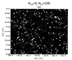
<도 60>
도 60은 복수의 BTS를 나타내는 도면으로서, 이들 중 일부는 양호한 SNR을 갖고, 이들 중 일부는 UE에 대해 낮은 도플러를 가짐.
<도 61>
도 61은 복수의 BTS-UE 링크에 대해 CP에 의해 기록된 SNR 및 도플러의 값들을 포함하는 행렬의 일 실시예를 나타내는 도면.
<도 62>
도 62는 본 발명의 일 실시예에 따른 상이한 시간들에서의 채널 이득(또는 CSI)을 나타내는 도면.BRIEF DESCRIPTION OF THE DRAWINGS A better understanding of the present invention can be obtained from the following detailed description taken in conjunction with the drawings.
≪ 1 >
BRIEF DESCRIPTION OF THE DRAWINGS Figure 1 is a diagram illustrating a primary DIDO cluster surrounded by neighboring DIDO clusters in one embodiment of the present invention.
2,
Figure 2 illustrates frequency division multiple access (FDMA) techniques used in an embodiment of the present invention.
3,
3 illustrates time division multiple access (TDMA) techniques used in an embodiment of the present invention.
<Fig. 4>
Figure 4 illustrates different types of interference zones that are addressed in an embodiment of the present invention.
5,
Figure 5 illustrates a framework used in an embodiment of the present invention.
6,
6 is a graph showing SER as a function of SNR, assuming SIR = 10 dB for the target client in the interference region;
7,
7 is a graph showing a SER derived from two IDCI pre-coding techniques;
8,
8 illustrates an exemplary scenario in which a target client moves from a primary DIDO cluster to an interfering cluster;
9,
9 shows a signal-to-interference plus noise ratio (SINR) as a function of distance D;
<Fig. 10>
10 is a diagram illustrating symbol error rate (SER) performance of three scenarios for 4-QAM modulation in flat-fading narrowband channels;
11)
11 is a diagram illustrating a method for IDCI pre-coding according to an embodiment of the present invention.
12,
Figure 12 shows SINR variation as a function of distance of a client from the center of the main DIDO clusters in one embodiment;
13,
13 illustrates one embodiment for deriving a SER for 4-QAM modulation;
<Fig. 14>
Figure 14 illustrates an embodiment of the present invention in which a finite state machine implements a handoff algorithm.
<Fig. 15>
Figure 15 illustrates one embodiment of a handoff strategy in the presence of shadowing;
<Fig. 16>
Figure 16 is a diagram illustrating a hysteresis loop mechanism when switching between any two states in Figure 93;
<Fig. 17>
17 illustrates one embodiment of a DIDO system that includes power control;
18,
18 illustrates SER versus SNR assuming four DIDO transmit antennas and four clients in different scenarios.
19,
19 illustrates MPE power density as a function of distance from a source of RF radiation to different values of transmit power, in accordance with an embodiment of the present invention;
20A and 20B,
20A and 20B show different distributions of low power and high power DIDO dispersion antennas;
21A and 21B,
Figures 21A and 21B show two power distributions corresponding respectively to the configurations of Figures 20A and 20B.
22A and 22B,
Figures 22A and 22B show rate distributions for the two scenarios shown in Figures 99A and 99B, respectively.
23,
23 illustrates one embodiment of a DIDO system that includes power control;
<Fig. 24>
Figure 24 illustrates one embodiment of a method that is repeated across all antenna groups in accordance with a round-robin scheduling policy to transmit data.
25,
Figure 25 shows a comparison of the uncoded SER performance of power control using antenna grouping and the traditional eigenmode selection in U.S. Patent No. 7,636,381.
26A to 26C,
Figures 26A-26C illustrate three scenarios in which BD pre-coding dynamically adjusts precoding weights to account for different power levels over wireless links between DIDO antennas and clients.
<Fig. 27>
FIG. 27 is a graphical representation of the delayed or instantaneous PDP (top plot) and frequency domain (bottom plot) low frequency selective channels (DIP) for DIDO 2x2 systems ![]()
28,
28 illustrates one embodiment of a channel matrix frequency response for DIDO 2x2 with a single antenna per client;
29,
29 is a graph showing the relationship between (for example, ![]()
30,
30 shows an exemplary SER for different QAM schemes (i.e., 4-QAM, 16-QAM, 64-QAM);
31,
31 illustrates one embodiment of a method for implementing link adaptation (LA) techniques.
<Fig. 32>
32 illustrates SER performance of one embodiment of link adaptation (LA) techniques.
33,
Figure 33 ![]()
![]()
34,
Figure 34 ![]()
<Fig. 35>
Figure 35 illustrates the different DIDO orders and ![]()
<Fig. 36>
36 illustrates one embodiment of a system that utilizes superclusters, DIDO clusters, and user clusters.
37,
37 illustrates a system having user clusters in accordance with one embodiment of the present invention.
38A and 38B,
Figures 38A and 38B show link quality metric thresholds used in an embodiment of the present invention.
≪ Figures 39 to 41 &
Figures 39-41 illustrate examples of link quality matrices for establishing user clusters.
42,
42 illustrates an embodiment in which a client moves across different DIDO clusters;
<Figs. 43 to 46>
Figures 43 to 46 illustrate relationships between the resolution of spherical arrays and their area (A) in an embodiment of the present invention.
47,
47 illustrates degrees of freedom of MIMO systems in actual indoor and outdoor propagation scenarios;
<Fig. 48>
Figure 48 shows degrees of freedom of DIDO systems as a function of array diameter.
49,
Figure 49 illustrates an embodiment that includes a centralized processor (CP) and a distributed node (DN) that communicate via wired or wireless connections.
<Fig. 50>
Figure 50 illustrates one embodiment in which CPs exchange control information with unauthorized DNs and reconfigure them to shut down frequency bands for authorized use.
51,
Figure 51 illustrates an embodiment in which the entire spectrum is assigned to a new service and CPs use control information to shut down all unauthorized DNs to prevent interference with authorized DNs.
52,
52 illustrates one embodiment of a cloud radio system that includes multiple CPs, distributed nodes, and networks interconnecting CPs to DNs;
<Figs. 53 to 59>
Figures 53-59 illustrate embodiments of a multiple user (MU) multiple antenna system (MAS) that adaptively reconfigure parameters to compensate for Doppler effects due to user mobility or changes in propagation environments. .
60,
60 shows a plurality of BTSs, some of which have good SNRs, some of which have low Doppler for UEs.
61,
61 illustrates one embodiment of a matrix including SNR and Doppler values recorded by a CP for a plurality of BTS-UE links;
62,
Figure 62 illustrates channel gain (or CSI) at different times according to an embodiment of the invention.
많은 전술한 종래 기술의 한계들을 극복하기 위한 하나의 솔루션은 분산 입력 분산 출력(Distributed-Input Distributed-Output, DIDO) 기술의 일 실시예이다. DIDO 기술은 아래의 특허들 및 특허 출원들에서 설명되며, 이들 모두는 본 특허의 양수인에게 양도되었고, 참고로 포함된다. 본 출원은 이들 특허 출원의 일부 연속 출원(CIP)이다. 이러한 특허들 및 출원들은 본 명세서에서 때때로 공동으로 "관련 특허들 및 출원들"로서 지칭된다.One solution to overcome many of the limitations of the prior art is one embodiment of Distributed-Input Distributed-Output (DIDO) technology. DIDO technology is described in the following patents and patent applications, all of which are assigned to the assignee of the present patent application and incorporated by reference. The present application is a continuation application (CIP) of these patent applications. Such patents and applications are sometimes referred to herein collectively as " Related Patents and Applications. &Quot;
"Systems And Methods To Exploit Areas of Coherence in Wirless Systems"라는 명칭으로 2011년 9월 14일자로 출원된 미국 출원 제13/232,996호;13 / 232,996, filed September 14, 2011, entitled " Systems And Methods To Exploit Areas Of Coherence in Wirless Systems ";
"Systems and Methods for Planned Evoluation and Obsolescence of Multiuser Spectrum"이라는 명칭으로 2011년 9월 14일자로 출원된 미국 출원 제13/233,006호;13 / 233,006, filed September 14, 2011, entitled " Systems and Methods for Planned Evolution and Obsolescence of Multiuser Spectrum ";
"Systems And Methods To Coordinate Transmissions In Distributed Wireless Systems Via User Clustering"이라는 명칭으로 2010년 11월 1일자로 출원된 미국 출원 제12/917,257호;U.S. Application No. 12 / 917,257, filed November 1, 2010, entitled " Systems And Methods To Coordinate Transmissions In Distributed Wireless Systems Via User Clustering ";
"Interference Management, Handoff, Power Control And Link Adaptation In Distributed-Input Distributed-Output (DIDO) Communication Systems"라는 명칭으로 2010년 6월 16일자로 출원된 미국 출원 제12/802,988호;U.S. Serial No. 12 / 802,988, filed June 16, 2010, entitled " Interference Management, Handoff, Power Control And Link Adaptation In Distributed-Input Distributed-Output (DIDO)
"System And Method For Adjusting DIDO Interference Cancellation Based On Signal Strength Measurements"라는 명칭으로 2010년 6월 16일자로 출원된 미국 출원 제12/802,976호;12 / 802,976, filed June 16, 2010, entitled " System And Method For Adjusting DIDO Interference Cancellation Based On Signal Strength Measurements ";
"System And Method For Managing Inter-Cluster Handoff Of Clients Which Traverse Multiple DIDO Clusters"라는 명칭으로 2010년 6월 16일자로 출원된 미국 출원 제12/802,974호;12 / 802,974, filed June 16, 2010, entitled " System And Method For Managing Inter-Cluster Handoff Of Clients Which Traverse Multiple DIDO Clusters ";
"System And Method For Managing Handoff Of A Client Between Different Distributed-Input-Distributed-Output (DIDO) Networks Based On Detected Velocity Of The Client"라는 명칭으로 2010년 6월 16일자로 출원된 미국 출원 제12/802,989호;12 / 802,989, filed June 16, 2010, entitled " System Based On Detected Velocity Of The Client ", entitled " System And Method For Managing Handoff Of A Client Between Different Distributed-Input-Distributed- ;
"System And Method For Power Control And Antenna Grouping In A Distributed-Input-Distributed-Output (DIDO) Network"라는 명칭으로 2010년 6월 16일자로 출원된 미국 출원 제12/802,958호;U.S. Serial No. 12 / 802,958, filed June 16, 2010, entitled " System And Method For Power Control And Antenna Grouping In A Distributed-Input-Distributed-Output (DIDO) Network;
"System And Method For Link adaptation In DIDO Multicarrier Systems"라는 명칭으로 2010년 6월 16일자로 출원된 미국 출원 제12/802,975호;12 / 802,975, filed June 16, 2010, entitled " System And Method For Link Adaptation In DIDO Multicarrier Systems ";
"System And Method For DIDO Precoding Interpolation In Multicarrier Systems"라는 명칭으로 2010년 6월 16일자로 출원된 미국 출원 제12/802,938호;12 / 802,938, filed June 16, 2010, entitled " System And Method For DIDO Precoding Interpolation In Multicarrier Systems ";
"System and Method For Distributed Antenna Wireless Communications"라는 명칭으로 2009년 12월 2일자로 출원된 미국 출원 제12/630,627호;12 / 630,627, filed December 2, 2009, entitled " System and Method for Distributed Antenna Wireless Communications ";
"System and Method for Distributed Input Distributed Output Wireless Communication"이라는 명칭으로 2007년 8월 20일자로 출원되고, 2009년 10월 6일자로 허여된 미국 특허 제7,599,420호;U.S. Patent No. 7,599,420, filed August 20, 2007, entitled " System and Method for Distributed Input Distributed Output Wireless Communication, " issued October 6, 2009;
"System and Method for Distributed Input Distributed Output Wireless Communication"라는 명칭으로 2007년 8월 20일자로 출원되고, 2009년 12월 15일자로 허여된 미국 특허 제7,633,994호;U.S. Patent No. 7,633,994, filed on August 20, 2007, entitled " System and Method for Distributed Input Distributed Output Wireless Communication, " issued December 15, 2009;
"System and Method for Distributed Input Distributed Output Wireless Communication"라는 명칭으로 2007년 8월 20일자로 출원되고, 2009년 12월 22일자로 허여된 미국 특허 제7,636,381호;U.S. Patent No. 7,636,381, filed on August 20, 2007, entitled " System and Method for Distributed Input Distributed Output Wireless Communication, " issued December 22, 2009;
"System and Method For Distributed Input-Distributed Output Wireless Communications"라는 명칭으로 2008년 6월 20일자로 출원된 미국 출원 제12/143,503호;U.S. Serial No. 12 / 143,503, filed June 20, 2008, entitled " System and Method For Distributed Input-Distributed Output Wireless Communications ";
"System and Method For Spatial-Multiplexed Tropospheric Scatter Communications"라는 명칭으로 2005년 10월 21일자로 출원된 미국 출원 제11/256,478호;U.S. Serial No. 11 / 256,478, filed October 21, 2005, entitled " System and Method For Spatial-Multiplexed Tropospheric Scatter Communications ";
"System and Method for Distributed Input Distributed Output Wireless Communication"이라는 명칭으로 2004년 7월 30일자로 출원되고, 2008년 8월 26일자로 허여된 미국 특허 제7,418,053호;U.S. Patent No. 7,418,053, filed July 30, 2004, entitled " System and Method for Distributed Input Distributed Output Wireless Communication ", issued Aug. 26, 2008;
"System and Method For Enhancing Near Vertical Incidence Skywave ("NVIS") Communication Using Space-Time Coding"이라는 명칭으로 2004년 4월 2일자로 출원된 미국 출원 제10/817,731호.U.S. Application Serial No. 10 / 817,731, filed April 2, 2004, entitled "System and Method For Enhancing Near Vertical Incidence Skywave (" NVIS ") Communication Using Space-Time Coding.
본 특허 출원의 분량 및 복잡성을 줄이기 위해, 관련 특허들 및 출원들 중 일부의 개시 내용은 아래에서 명확히 기재되지 않는다. 개시 내용의 충분한 상세한 설명에 대해서는 관련 특허들 및 출원들을 참고하기 바란다.To reduce the amount and complexity of the present patent application, the disclosures of some of the related patents and applications are not explicitly described below. For a detailed description of the disclosure, please refer to related patents and applications.
아래의 섹션 I(관련 출원 제12/802,988호로부터의 개시 내용)은 종래 기술의 참고 문헌들 및 본 출원의 양수인에게 양도된 종래의 출원들을 지칭하는 그 자신의 엔드노트들의 세트를 이용한다는 점에 유의한다. 엔드노트 인용문들은 섹션 I의 끝에 (섹션 II의 제목 바로 전에) 목록화된다. 섹션 II 사용들 내의 인용문들은 섹션 I에서 사용되는 것들과 중복되는 그의 인용문들에 대한 숫자 표시들을 가질 수 있지만, 이러한 숫자 표시들은 (섹션 II의 끝에 목록화되는) 상이한 참고 문헌들을 식별한다. 따라서, 특정 숫자 표시에 의해 식별되는 참고 문헌들은 숫자 표시가 사용되는 섹션 내에서 식별될 수 있다.The following Section I (the disclosure of which is incorporated by reference in its entirety) discloses the use of a set of endnotes of its own designating prior art references and conventional applications assigned to the assignee of the present application Please note. End note quotations are listed at the end of Section I (just before the title of Section II). The quotations in Section II uses may have numerical representations of their quotations that overlap with those used in Section I, but such numeric representations identify different references (listed at the end of Section II). Thus, references identified by particular numeric representations may be identified within the section in which the numerical indicia is used.
I. 관련 출원 제12/802,988호로부터의 개시 내용I. INTRODUCTION FROM
1. 클러스터간 간섭을 제거하기 위한 방법들1. Methods for eliminating intercluster interference
아래에서는 복수의 분산 송신 안테나를 이용하여 0의 무선 주파수(radio frequency, RF) 에너지를 갖는 공간 내의 위치들을 생성하는 무선 RF 통신 시스템들 및 방법들이 설명된다. M개의 송신 안테나가 사용될 때, 사전 정의된 위치들 내에 0의 RF 에너지의 최대 (M-1)개의 포인트를 생성하는 것이 가능하다. 본 발명의 일 실시예에서, 0 RF 에너지의 포인트들은 무선 장치들이며, 송신 안테나들은 송신기들과 수신기들 사이의 채널 상태 정보(channel state information, CSI)를 안다. 일 실시예에서, CSI는 수신기들에서 계산되고, 송신기들로 피드백된다. 다른 실시예에서, CSI는 채널 상호성의 이용을 가정하여, 수신기들로부터의 훈련을 통해 송신기에서 계산된다. 송신기들은 CSI를 이용하여, 동시에 전송될 간섭 신호들을 결정할 수 있다. 일 실시예에서, 송신 안테나들에서 블록 대각화(block diagonalization, BD) 사전 코딩을 이용하여 0 RF 에너지의 포인트들을 생성한다.In the following, wireless RF communication systems and methods for generating positions within a space with a radio frequency (RF) energy of zero using a plurality of distributed transmit antennas are described. When M transmit antennas are used, it is possible to generate a maximum of (M-1) points of RF energy of zero within the predefined positions. In one embodiment of the present invention, the points of zero RF energy are wireless devices, and the transmit antennas know channel state information (CSI) between transmitters and receivers. In one embodiment, the CSI is calculated at the receivers and fed back to the transmitters. In another embodiment, the CSI is calculated at the transmitter through training from receivers, assuming the use of channel reciprocity. Transmitters can use CSI to determine interference signals to be transmitted simultaneously. In one embodiment, block diagonalization (BD) precoding at the transmit antennas is used to generate points of zero RF energy.
본 명세서에 설명되는 시스템 및 방법들은 전술된 전통적인 수신/송신 빔 형성 기술들과 다르다. 사실상, 수신 빔 형성은 (널-스티어링을 통해) 수신 측에서 간섭을 억압하도록 가중치들을 계산하는 반면, 본 명세서에 설명되는 본 발명의 일부 실시예들은 "0 RF 에너지"를 갖는 공간 내의 하나 또는 다수의 위치를 유발하는 간섭 패턴들을 생성하기 위해 송신 측에서 가중치들을 적용한다. 모든 사용자에 대한 신호 품질(또는 SINR) 또는 다운링크 처리량을 각각 최대화하도록 설계되는 전통적인 송신 빔 형성 또는 BD 사전 코딩과 달리, 본 명세서에 설명되는 시스템들 및 방법들은 소정 조건들 하에서 그리고/또는 소정의 송신기들로부터 신호 품질을 최소화하여, (본 명세서에서, 때때로 "사용자들"로서 지칭되는) 클라이언트 장치들에서 0 RF 에너지의 포인트들을 생성한다. 더욱이, (우리의 관련 특허들 및 출원들에서 설명되는) 분산 입력 분산 출력(DIDO) 시스템들과 관련하여, 공간 내에 분산되는 송신 안테나들은 상이한 사용자들에 대한 0 RF 에너지 및/또는 최대 SINR의 다수의 포인트를 생성하는 데 이용될 수 있는 더 높은 자유도(즉, 더 높은 채널 공간 다이버시티)를 제공한다. 예를 들어, M개의 송신 안테나를 이용할 경우, RF 에너지의 최대 (M-1)개의 포인트를 생성하는 것이 가능하다. 이와 달리, 실제의 빔 형성 또는 BD 다중 사용자 시스템들은 통상적으로 임의의 수(M)의 송신 안테나에 대해 무선 링크를 통해 서비스될 수 있는 동시 사용자들의 수를 제한하는 송신 측에서의 가까이 이격된 안테나들을 갖도록 설계된다.The systems and methods described herein differ from the conventional receive / transmit beamforming techniques described above. In fact, receive beamforming computes weights to suppress interference at the receiving end (via null-steering), while some embodiments of the present invention described herein may use one or more Lt; RTI ID = 0.0 > of interference < / RTI > Unlike traditional transmit beamforming or BD pre-coding, which is designed to maximize signal quality (or SINR) or downlink throughput for all users, respectively, the systems and methods described herein may be used under certain conditions and / Minimizes the signal quality from the transmitters to generate points of zero RF energy in the client devices (sometimes referred to herein as " users "). Moreover, with respect to distributed input dispersion output (DIDO) systems (as described in our related patents and applications), transmit antennas dispersed in space can have zero RF energy and / or a large number of maximum SINRs for different users (E. G., Higher channel space diversity) that can be used to generate points of view. For example, when using M transmit antennas, it is possible to generate a maximum of (M-1) points of RF energy. Alternatively, actual beamforming or BD multi-user systems are typically designed to have near-spaced antennas on the transmit side that limit the number of concurrent users that can be serviced over the air link for any number (M) of transmit antennas do.
M개의 송신 안테나 및 K명의 사용자를 포함하는 시스템을 고려하며, 이때 K<M이다. 송신기가 M개의 송신 안테나와 K명의 사용자 사이의 CSI (![]()
![]()
![]()
![]()
![]()
![]()
여기서, ![]()
![]()
![]()
![]()

일 실시예에서, 채널 행렬 H의 특이 값 분해(singular value decomposition, SVD)가 계산되고, 사전 코딩 가중치 w가 H의 (0 특이 값에 의해 식별되는) 널 하위 공간에 대응하는 우측 특이 벡터로서 정의된다.In one embodiment, a singular value decomposition (SVD) of the channel matrix H is computed, and the precoding weight w is defined as a right singular vector corresponding to a null subspace (identified by a zero singular value) of H do.
송신 안테나들은 위에서 정의된 가중 벡터를 이용하여 RF 에너지를 송신하는 한편, K명의 사용자의 위치들에서 0 RF 에너지의 K개의 포인트를 생성하며, 따라서 k 번째 사용자에서 수신된 신호는 아래 수학식에 의해 주어진다.The transmit antennas transmit the RF energy using the weight vectors defined above, while generating K points of zero RF energy at the positions of the K users, so that the signal received at the kth user is given by Given.
![]()
![]()
여기서, ![]()
![]()
일 실시예에서, 채널 행렬 H의 특이 값 분해(SVD)가 계산되고, 사전 코딩 가중치 w가 H의 (0 특이 값에 의해 식별되는) 널 하위 공간에 대응하는 우측 특이 벡터로서 정의된다.In one embodiment, the singular value decomposition (SVD) of the channel matrix H is computed and the precoding weight w is defined as the right singular vector corresponding to a null subspace (identified by a zero singular value) of H. [
다른 실시예에서, 무선 시스템은 DIDO 시스템이고, 0 RF 에너지의 포인트들은 상이한 DIDO 커버리지 영역들 사이에서 클라이언트들에 대한 간섭을 사전 제거하도록 생성된다. 미국 출원 제12/630,627호에서는, 아래의 요소들을 포함하는 DIDO 시스템이 설명된다.In another embodiment, the wireless system is a DIDO system and the points of zero RF energy are generated to pre-remove interference to clients between different DIDO coverage areas. In U.S. Serial No. 12 / 630,627, a DIDO system is described that includes the following elements.
· DIDO 클라이언트들· DIDO clients
· DIDO 분산 안테나들· DIDO dispersion antennas
· DIDO 기지 송수신기국들(base transceiver stations, BTS)DIDO base transceiver stations (BTS)
· DIDO 기지국 네트워크(base station network, BSN)DIDO base station network (BSN)
모든 BTS는 DIDO 클러스터라고 하는 주어진 커버리지 영역에 서비스를 제공하는 다수의 분산 안테나에 BSN을 통해 접속된다. 본 특허 출원에서는, 인접하는 DIDO 클러스터들 사이의 간섭을 제거하기 위한 시스템 및 방법이 설명된다. 도 1에 도시된 바와 같이, 주요 DIDO 클러스터가 이웃 클러스터들로부터의 간섭에 의해 영향을 받는 클라이언트(즉, 다중 사용자 DIDO 시스템에 의해 서빙되는 사용자 장치)(또는 타겟 클라이언트)를 호스트하는 것으로 가정한다.All BTSs are connected via BSN to a number of distributed antennas serving a given coverage area called a DIDO cluster. In this patent application, a system and method for eliminating interference between adjacent DIDO clusters is described. As shown in FIG. 1, it is assumed that a primary DIDO cluster hosts a client (i.e., a user device served by a multi-user DIDO system) (or a target client) that is affected by interference from neighboring clusters.
일 실시예에서, 이웃 클러스터들은 전통적인 셀룰러 시스템들과 유사한 주파수 분할 다중 액세스(FDMA) 기술들에 따라 상이한 주파수들에서 동작한다. 예를 들어, 3의 주파수 재사용 팩터의 경우, 도 2에 도시된 바와 같이, 제3 DIDO 클러스터마다 동일 캐리어 주파수가 재사용된다. 도 2에서, 상이한 캐리어 주파수들은 F1, F2 및 F3로 식별된다. 이 실시예는 일부 구현들에서 사용될 수 있지만, 이러한 솔루션은 스펙트럼 효율의 손실을 유발하는데, 그 이유는 이용 가능 스펙트럼이 다수의 하위 대역으로 분할되고, DIDO 클러스터들의 서브세트만이 동일 하위 대역에서 동작하기 때문이다. 더욱이, 이것은 상이한 DIDO 클러스터들을 상이한 주파수들에 연관시켜 간섭을 방지하기 위해 복잡한 셀 계획을 필요로 한다. 종래 기술의 셀룰러 시스템들과 같이, 그러한 셀룰러 계획은 동일 주파수를 사용하는 클러스터들 간의 간섭을 방지하기 위해 안테나들의 특정 배치 및 송신 전력의 제한을 필요로 한다.In one embodiment, neighboring clusters operate at different frequencies in accordance with frequency division multiple access (FDMA) techniques similar to traditional cellular systems. For example, in the case of a frequency reuse factor of 3, the same carrier frequency is reused for every third DIDO cluster, as shown in FIG. In Figure 2, the different carrier frequencies are identified as F 1 , F 2 and F 3 . Although this embodiment may be used in some implementations, such a solution causes loss of spectral efficiency because the available spectrum is divided into multiple subbands, and only a subset of DIDO clusters operate in the same subband . Moreover, this requires a complex cell scheme to associate different DIDO clusters with different frequencies to prevent interference. As with prior art cellular systems, such cellular plans require specific arrangements of antennas and limitations of transmit power to prevent interference between clusters using the same frequency.
다른 실시예에서, 이웃 클러스터들은 동일 주파수 대역에서, 그러나 시분할 다중 액세스(TDMA) 기술에 따라 상이한 시간 슬롯들에서 동작한다. 예를 들어, 도 3에 도시된 바와 같이, DIDO 송신은 도시된 바와 같이 소정의 클러스터들에 대해 시간 슬롯 T1, T2 및 T3에서만 허용된다. 시간 슬롯들은 상이한 클러스터들에 동일하게 할당될 수 있으며, 따라서 상이한 클러스터들은 라운드 로빈 정책에 따라 스케줄링된다. 상이한 클러스터들이 상이한 데이터 레이트 요구들에 의해 특성화되는 경우(즉, 커버리지 영역마다 더 적은 수의 클라이언트를 갖는 시골 영역들 내의 클러스터들과 달리 붐비는 도시 환경들 내의 클러스터들), 상이한 우선 순위들이 상이한 클러스터들에 할당되며, 따라서 더 많은 시간 슬롯이 더 큰 데이터 레이트 요구들을 갖는 클러스터들에 할당된다. 전술된 바와 같은 TDMA가 본 발명의 일 실시예에서 사용될 수 있지만, TDMA 접근법은 상이한 클러스터들에 걸쳐 시간 동기화를 필요로 할 수 있으며, 간섭 클러스터들이 동일 주파수를 동시에 사용할 수 없으므로 스펙트럼 효율을 저하시킬 수 있다.In another embodiment, neighboring clusters operate in the same frequency band, but in different time slots according to the time division multiple access (TDMA) technique. For example, as shown in FIG. 3, DIDO transmissions are only allowed in time slots T 1 , T 2, and T 3 for certain clusters as shown. The time slots can be equally allocated to different clusters, so different clusters are scheduled according to the round robin policy. When different clusters are characterized by different data rate requirements (i.e. clusters in crowded urban environments, unlike clusters in rural areas with fewer clients per coverage area), different priorities are different clusters , So that more time slots are allocated to clusters with larger data rate demands. Although the TDMA as described above may be used in one embodiment of the present invention, the TDMA approach may require time synchronization across different clusters, and since interference clusters can not simultaneously use the same frequency, have.
일 실시예에서, 모든 이웃 클러스터들은 동일 주파수 대역에서 동시에 송신하며, 클러스터들에 걸쳐 공간 처리를 이용하여 간섭을 방지한다. 이 실시예에서, 다중 클러스터 DIDO 시스템은 (i) (제7,599,420호; 제7,633,994호; 제7,636,381호; 및 출원 제12/143,503호를 포함하는 관련 특허들 및 출원들에서 설명되는 바와 같이) 주요 클러스터 내에서 전통적인 DIDO 사전 코딩을 이용하여 동일 주파수 대역 내에서 동시적인 비간섭 데이터 스트림들을 다수의 클라이언트로 전송하고; (ii) 타겟 클라이언트들의 위치들에서 0 무선 주파수(RF) 에너지의 포인트들을 생성함으로써 도 4의 간섭 구역들(8010) 내에 위치하는 클라이언트들에 대한 간섭을 방지하기 위해 이웃 클러스터들에서의 간섭 제거와 함께 DIDO 사전 코딩을 이용한다. 타겟 클라이언트가 간섭 구역(410) 내에 있는 경우, 주요 클러스터(411)로부터의 데이터 스트림 및 간섭 클러스터(412-413)로부터의 0 RF 에너지를 포함하는 RF의 합을 수신할 것이며, 이는 단지 주요 클러스터로부터의 데이터 스트림을 포함하는 RF일 것이다. 따라서, 인접 클러스터들은 동일 주파수를 동시에 이용할 수 있으며, 이때 간섭 구역 내의 타겟 클라이언트들은 간섭을 겪지 않는다.In one embodiment, all neighboring clusters transmit simultaneously in the same frequency band and use spatial processing across the clusters to prevent interference. In this embodiment, the multi-cluster DIDO system includes a primary cluster (i) (as described in related patents and applications including applications 7,599,420, 7,633,994, 7,636,381, and 12 / 143,503, Transmitting concurrent non-interfering data streams in the same frequency band to multiple clients using traditional DIDO dictionary coding; (ii) interference elimination in neighboring clusters to prevent interference to clients located in the interference zones 8010 of FIG. 4 by generating points of zero radio frequency (RF) energy at the locations of the target clients Together we use DIDO dictionary coding. When the target client is in the
실제의 시스템들에서, DIDO 사전 코딩의 성능은 (DIDO 분산 안테나들에서 쓸모 없는 채널 상태 정보를 생성하는) 채널 추정 에러 또는 도플러 효과들; 멀티캐리어 DIDO 시스템들에서의 변조간 왜곡(intermodulation distortion, IMD); 시간 또는 주파수 오프셋들과 같은 상이한 팩터들에 의해 영향을 받을 수 있다. 이러한 효과들의 결과로서, 0 RF 에너지의 포인트들을 달성하는 것이 불가능할 수 있다. 그러나, 간섭 클러스터들로부터의 타겟 클라이언트에서의 RF 에너지가 주요 클러스터로부터의 RF 에너지에 비해 무시될 수 있는 한, 타겟 클라이언트에서의 링크 성능은 간섭에 의해 영향을 받지 않는다. 예를 들어, 클라이언트가 10-6의 타겟 비트 에러 레이트(bit error rate, BER)를 달성하기 위해 순방향 에러 정정(forward error correction, FEC) 코딩을 이용하여 4-QAM 배열들을 복조하기 위해 20 dB 신호 대 잡음비(SNR)를 필요로 하는 것으로 가정한다. 간섭 클러스터로부터 수신되는 타겟 클라이언트에서의 RF 에너지가 주요 클러스터로부터 수신되는 RF 에너지보다 20 dB 낮은 경우, 간섭은 무시될 수 있으며, 클라이언트는 사전 정의된 BER 타겟 내에서 성공적으로 데이터를 복조할 수 있다. 따라서, 본 명세서에 사용되는 바와 같은 "0 RF 에너지"라는 용어는 간섭 RF 신호들로부터의 RF 에너지가 0이라는 것을 반드시 의미하지는 않는다. 오히려, 이것은 RF 에너지가 원하는 RF 신호의 RF 에너지에 비해 충분히 낮으며, 따라서 원하는 RF 신호가 수신기에서 수신될 수 있다는 것을 의미한다. 더욱이, 원하는 RF 에너지에 대한 간섭 RF 에너지의 소정의 바람직한 임계치들이 설명되지만, 본 발명의 기본 원리들은 임의의 특정 임계치 값들로 제한되지 않는다.In practical systems, the performance of DIDO pre-coding may include channel estimation errors or Doppler effects (which generate useless channel state information in DIDO distributed antennas); Intermodulation distortion (IMD) in multi-carrier DIDO systems; Such as time or frequency offsets. ≪ RTI ID = 0.0 > As a result of these effects, it may be impossible to achieve the points of zero RF energy. However, as long as the RF energy at the target client from the interference clusters can be ignored relative to the RF energy from the main cluster, the link performance at the target client is not affected by interference. For example, to demodulate 4-QAM arrays using forward error correction (FEC) coding to achieve a target bit error rate (BER) of 10 -6 , Noise ratio (SNR) is required. If the RF energy at the target client received from the interference cluster is 20 dB lower than the RF energy received from the main cluster, the interference can be ignored and the client can successfully demodulate the data within the predefined BER target. Thus, the term " 0 RF energy " as used herein does not necessarily mean that the RF energy from the interfering RF signals is zero. Rather, this means that the RF energy is sufficiently low compared to the RF energy of the desired RF signal, and therefore the desired RF signal can be received at the receiver. Moreover, although certain desirable thresholds of interference RF energy for a desired RF energy are described, the basic principles of the present invention are not limited to any particular threshold values.
도 4에 도시된 바와 같이 상이한 타입의 간섭 구역들(8010)이 존재한다. 예를 들어, (도 80에 문자 "A"로 지시되는 바와 같은) "타입 A" 구역들은 단지 하나의 이웃 클러스터로부터의 간섭에 의해 영향을 받는 반면, (문자 "B"로 지시되는 바와 같은) "타입 B" 구역들은 2개 또는 다수의 이웃 클러스터로부터의 간섭을 설명한다.There are different types of interference zones 8010, as shown in FIG. For example, "Type A" zones (as indicated by the letter "A" in FIG. 80) are affected by interference from only one neighbor cluster, while (as indicated by the letter "B" &Quot; Type B " zones describe interference from two or more neighboring clusters.
도 5는 본 발명의 일 실시예에서 사용되는 프레임워크를 나타낸다. 점들은 DIDO 분산 안테나들을 나타내고, 십자가들은 DIDO 클라이언트들을 나타내고, 화살표들은 RF 에너지의 전파 방향들을 나타낸다. 주요 클러스터 내의 DIDO 안테나들은 사전 코딩된 데이터 신호들을 그 클러스터 내의 클라이언트들 MC(501)로 전송한다. 또한, 간섭 클러스터 내의 DIDO 안테나들은 전통적인 DIDO 사전 코딩을 통해 클러스터 내의 클라이언트들 IC(502)를 서빙한다. 녹색 십자가(503)는 간섭 구역 내의 타겟 클라이언트 TC(503)를 나타낸다. 주요 클러스터(511) 내의 DIDO 안테나들은 전통적인 DIDO 사전 코딩을 통해 사전 코딩된 데이터 신호들을 타겟 클라이언트로(흑색 화살표들) 전송한다. 간섭 클러스터(512) 내의 DIDO 안테나들은 사전 코딩을 이용하여 타겟 클라이언트(503)의 방향들을 향하는(녹색 화살표들) 0 RF 에너지를 생성한다.Figure 5 shows a framework used in an embodiment of the present invention. The dots represent the DIDO dispersion antennas, the crosses represent the DIDO clients, and the arrows represent the propagation directions of the RF energy. The DIDO antennas in the primary cluster transmit the pre-coded data signals to the
도 4의 임의의 간섭 구역(410A, B) 내의 타겟 클라이언트 k에서 수신된 신호는 아래 수학식에 의해 주어진다.The signal received at the target client k in any of the interference regions 410A, B of FIG. 4 is given by the following equation.
![]()
![]()
여기서, k=1,..,K이고, 이때 K는 간섭 구역(8010A, B) 내의 클라이언트들의 수이고, U는 주요 DIDO 클러스터 내의 클라이언트들의 수이고, C는 간섭 DIDO 클러스터들(412-413)의 수이고, ![]()
![]()
![]()
![]()
![]()
![]()
![]()
![]()
![]()
![]()
![]()
![]()
![]()
![]()
![]()
![]()
![]()
![]()
![]()
![]()
![]()
![]()
표기법을 간소화하기 위해 그리고 일반성의 손실 없이, 모든 클라이언트들은 N개의 수신 안테나를 구비하고, 모든 DIDO 클러스터 내에는 M개의 DIDO 분산 안테나가 존재하는 것으로 가정하며, 이때 ![]()
![]()
![]()
![]()
DIDO 사전 코딩 가중치들은 동일 DIDO 클러스터 내의 클라이언트간 간섭을 사전 제거하도록 계산된다. 예를 들어, 제7,599,420호; 제7,633,994호; 제7,636,381호; 및 출원 제12/143,503호 및 [7]을 포함하는 관련 특허들 및 출원들에 설명된 블록 대각화(BD) 사전 코딩이 클라이언트간 간섭을 제거하는 데 사용될 수 있으며, 따라서 주요 클러스터에서 아래의 조건이 충족된다.The DIDO pre-coding weights are calculated to pre-remove inter-client interference in the same DIDO cluster. See, for example, U.S. Patent No. 7,599,420; 7,633,994; 7,636,381; And BD diagonalization (BD) precoding as described in related patents and
![]()
![]()
이웃 DIDO 클러스터들에서의 사전 코딩 가중 행렬들은 아래의 조건이 충족되도록 설계된다.The precoding weighted matrices in neighboring DIDO clusters are designed to satisfy the following conditions.
![]()
![]()
사전 코딩 행렬들 ![]()
![]()
![]()
![]()
![]()
![]()
여기서, ![]()
![]()
![]()
![]()
조건 2 및 3을 1에 대입하면, 타겟 클라이언트 k에 대한 수신된 데이터 스트림들이 얻어지며, 여기서는 클러스터내 및 클러스터간 간섭이 제거된다.Substituting
![]()
![]()
이웃 클러스터들에서 계산된 수학식 1의 사전 코딩 가중치들 ![]()
![]()
![]()
![]()
여기서, ![]()
![]()
제안되는 방법의 성능을 신호 대 잡음비(SNR)의 함수로서 심벌 에러 레이트(SER)와 관련하여 평가하는 것으로부터 시작한다. 일반성의 손실 없이, 클라이언트당 단일 안테나를 가정하여 아래의 신호 모델을 정의하고, 수학식 1을 아래와 같이 재구성한다.We begin by evaluating the performance of the proposed method in relation to the symbol error rate (SER) as a function of signal to noise ratio (SNR). Assuming a single antenna per client without loss of generality, we define the following signal model and reconstruct equation (1) as follows.
![]()
![]()
여기서, INR은 INR=SNR/SIR로서 정의되는 간섭 대 잡음비이고, SIR은 신호 대 간섭비이다.Where INR is the interference-to-noise ratio defined as INR = SNR / SIR, and SIR is the signal-to-interference ratio.
도 6은 간섭 구역 내의 타겟 클라이언트에 SIR=10 dB를 가정하여, SER을 SNR의 함수로서 나타내고 있다. 일반성의 손실 없이, 4-QAM 및 16-QAM에 대한 SER을 순방향 에러 정정(FEC) 코딩 없이 측정하였다. 코딩되지 않은 시스템들에 대해 타겟 SER을 1%로 고정한다. 이 타겟은 변조 차수에 따라 SNR의 상이한 값들에 대응한다(즉, 4-QAM에 대해 SNR=20 dB 및 16-QAM에 대해 SNR=28 dB). 코딩 이득으로 인해 FEC 코딩을 사용할 때 SNR의 동일 값들에 대해 더 낮은 SER 타겟들이 충족될 수 있다. 클러스터당 2개의 DIDO 안테나 및 (각자 단일 안테나를 구비하는) 2개의 클라이언트를 갖는 2개의 클러스터(하나의 주요 클러스터 및 하나의 간섭 클러스터)의 시나리오를 고려한다. 주요 클러스터 내의 클라이언트들 중 하나는 간섭 구역 내에 위치한다. 플랫-페이딩 협대역 채널들을 가정하지만, 아래의 결과들은 각각의 서브캐리어가 플랫 페이딩을 겪는 주파수 선택 멀티캐리어(OFDM) 시스템들로 확장될 수 있다. 2개의 시나리오, 즉 (i) 간섭 구역 내의 타겟 클라이언트를 설명하지 않고서 사전 코딩 가중치들 ![]()
![]()
![]()
![]()
도 6의 결과들은 수학식 5에서와 같이 IDCI 사전 코딩을 가정한다. 이웃 클러스터들에서의 IDCI 사전 코딩이 수학식 6에서와 같이 간섭 구역 내의 타겟 클라이언트로의 데이터 스트림들을 사전 코딩하는 데에도 사용되는 경우, 추가적인 다이버시티 이득이 얻어진다. 도 7은 두 가지 기술, 즉 (i) 수학식 5에서의 IDCI 사전 코딩을 이용하는 "방법 1"; (ii) 이웃 클러스터들이 또한 사전 코딩된 데이터 스트림을 타겟 클라이언트로 전송하는 수학식 6에서의 IDCI 사전 코딩을 이용하는 "방법 2"로부터 도출된 SER을 비교한다. 방법 2는 사전 코딩된 데이터 스트림을 타겟 클라이언트로 전송하는 데 사용되는 이웃 클러스터 내의 DIDO 안테나들에 의해 제공되는 추가적인 어레이 이득으로 인해 전통적인 IDCI 사전 코딩에 비해 약 3 dB 이득을 생성한다. 더 일반적으로, 방법 1에 대한 방법 2의 어레이 이득은 10*log10(C+1)에 비례하며, 여기서 C는 이웃 클러스터들의 수이고, 팩터 "1"은 주요 클러스터를 나타낸다.The results of FIG. 6 assume IDCI pre-coding as in
이어서, 위의 방법의 성능을 간섭 구역에 대한 타겟 클라이언트의 위치의 함수로서 평가한다. 도 8에 도시된 바와 같이, 타겟 클라이언트(8401)가 주요 DIDO 클러스터(802)로부터 간섭 클러스터(803)로 이동하는 하나의 간단한 시나리오를 고려한다. 주요 클러스터(802) 내의 모든 DIDO 안테나들(812)이 BD 사전 코딩을 이용하여 클러스터간 간섭을 제거함으로써 조건 2를 충족시키는 것으로 가정한다. 단일 간섭 DIDO 클러스터, 클라이언트 장치(801)에서의 단일 수신기 안테나 및 주요 또는 간섭 클러스터 내의 모든 DIDO 안테나들로부터 클라이언트로의 동일한 경로 손실(즉, DIDO 안테나들이 클라이언트 주위의 원 안에 배치됨)을 가정한다. (통상적인 도시 환경들에서와 같이) 경로 손실 지수 4를 갖는 하나의 간이 경로 손실 모델을 이용한다 [11].The performance of the above method is then evaluated as a function of the location of the target client relative to the interference zone. Consider a simple scenario in which the target client 8401 moves from the primary DIDO cluster 802 to the interfering cluster 803, as shown in FIG. It is assumed that all
이하의 분석은 경로 손실을 설명하기 위해 수학식 7을 확장하는 아래의 간이 신호 모델에 기초한다.The following analysis is based on the following simplified signal model extending equation (7) to account for path loss.

여기서, 신호 대 간섭비(SIR)는 SIR=((1-D)/D)4로서 도출된다. IDCI의 모델링에서, 3개의 시나리오, 즉 i) IDCI가 없는 이상적인 사례; (ii) 조건 3을 충족시키기 위해 간섭 클러스터에서의 BD 사전 코딩을 통해 IDCI가 사전 제거된 사례; iii) 이웃 클러스터에 의해 사전 제거되지 않은 IDCI를 갖는 사례를 고려한다.Here, the signal-to-interference ratio (SIR) is derived as SIR = ((1-D) / D) 4 . In IDCI's modeling, three scenarios, i) an ideal case without an IDCI; (ii) an IDCI was pre-removed through BD pre-coding in an interference cluster to satisfy
도 9는 D의 함수로서의 (즉, 타겟 클라이언트가 주요 클러스터(802)로부터 간섭 클러스터(8403) 내의 DIDO 안테나들(813)을 향해 이동할 때의) 신호 대 간섭 플러스 잡음비(SINR)를 나타낸다. SINR은 수학식 8의 신호 모델을 이용하여 신호 전력 대 간섭 플러스 잡음 전력의 비율로서 도출된다. Do=0.1 및 D=Do에 대해 SNR=50 dB인 것으로 가정한다. IDCI의 부재 시에, 무선 링크 성능은 잡음에 의해서만 영향을 받으며, SINR은 경로 손실로 인해 감소한다. IDCI의 존재 시에(즉, IDCI 사전 코딩이 없는 경우), 이웃 클러스터 내의 DIDO 안테나들로부터의 간섭은 SINR의 감소에 기여한다.9 shows the signal to interference plus noise ratio (SINR) as a function of D (i.e., when the target client moves from the primary cluster 802 towards the DIDO antennas 813 in the interference cluster 8403). SINR is derived as a ratio of signal power to interference plus noise power using the signal model of equation (8). For D o = 0.1 and D = D o is assumed that the SNR = 50 dB. In the absence of IDCI, the radio link performance is only affected by noise, and the SINR decreases due to path loss. In the presence of the IDCI (i.e., without IDCI pre-coding), the interference from the DIDO antennas in the neighboring cluster contributes to the reduction of the SINR.
도 10은 플랫 페이딩 협대역 채널들에서의 4-QAM 변조에 대한 위의 3개의 시나리오의 심벌 에러 레이트(SER) 성능을 나타낸다. 이러한 SER 결과들은 도 9의 SINR에 대응한다. 도 9의 SINR 임계치 SINRT=20 dB에 대응하는 코딩되지 않은 (즉, FEC 없는) 시스템들에 대한 1%의 SER 임계치를 가정한다. SINR 임계치는 데이터 송신에 사용되는 변조 차수에 의존한다. 더 높은 변조 차수들은 통상적으로 동일 타겟 에러 레이트를 달성하기 위해 더 높은 SINRT에 의해 특성화된다. FEC를 이용할 경우, 코딩 이득으로 인해 동일 SINR 값에 대해 더 낮은 타겟 SER이 달성될 수 있다. 사전 코딩이 없는 IDCI의 경우, 타겟 SER은 범위 D<0.25 내에서만 달성된다. 이웃 클러스터에서의 IDCI 사전 코딩의 경우, 타겟 SER을 충족시키는 범위는 D<0.6까지 확장된다. 그 범위를 초과하면, SINR은 경로 손실로 인해 증가하며, SER 타겟은 충족되지 않는다.Figure 10 shows symbol error rate (SER) performance of the above three scenarios for 4-QAM modulation in flat fading narrowband channels. These SER results correspond to the SINR of FIG. Assume a 1% SER threshold for un-coded (i.e., no FEC) systems corresponding to the SINR threshold SINR T = 20 dB in FIG. The SINR threshold depends on the modulation order used for data transmission. Higher modulation orders are typically characterized by a higher SINR T to achieve the same target error rate. With FEC, a lower target SER for the same SINR value can be achieved due to the coding gain. For IDCIs without pre-coding, the target SER is achieved only within the range D <0.25. In the case of IDCI pre-coding in the neighboring cluster, the range satisfying the target SER is extended to D < 0.6. Beyond that range, the SINR increases due to path loss, and the SER target is not satisfied.
IDCI 사전 코딩을 위한 방법의 일 실시예가 도 11에 도시되며, 아래의 단계들로 구성된다.One embodiment of a method for IDCI pre-coding is shown in FIG. 11 and consists of the following steps.
· SIR 추정(1101): 클라이언트들은 주요 DIDO 클러스터로부터 (즉, 수신된 사전 코딩 데이터에 기초하여) 신호 전력을 그리고 이웃 DIDO 클러스터들로부터 간섭 플러스 잡음 신호 전력을 추정한다. 단일 캐리어 DIDO 시스템들에서, 프레임 구조는 짧은 침묵 기간들을 갖도록 설계될 수 있다. 예를 들어, 침묵 기간들은 채널 추정을 위한 훈련과 채널 상태 정보(CSI) 피드백 동안의 사전 코딩된 데이터 송신 사이에 정의될 수 있다. 일 실시예에서, 이웃 클러스터들로부터의 간섭 플러스 잡음 신호 전력은 주요 클러스터 내의 DIDO 안테나들로부터 침묵 기간들 동안 측정된다. 실제의 DIDO 멀티캐리어(OFDM) 시스템들에서는, 송신 및 수신 측들에서의 필터링으로 인한 대역의 에지에서의 직류(DC) 오프셋 및 감쇠를 방지하기 위해 통상적으로 널 톤들이 사용된다. 멀티캐리어 시스템들을 이용하는 다른 실시예에서, 간섭 플러스 잡음 신호 전력은 널 톤들로부터 추정된다. 대역의 에지에서의 송신/수신 필터 감쇠를 보상하기 위해 정정 팩터들이 사용될 수 있다. 주요 클러스터로부터의 신호 플러스 간섭 및 잡음 전력(PS)과 이웃 클러스터들로부터의 간섭 플러스 잡음 전력(PIN)이 추정되면, 클라이언트는 아래와 같이 SINR을 계산한다.SIR estimation 1101: Clients estimate the signal power from the primary DIDO cluster (i.e., based on the received precoded data) and the interference plus noise signal power from neighboring DIDO clusters. In single carrier DIDO systems, the frame structure may be designed to have short periods of silence. For example, silence periods may be defined between training for channel estimation and pre-coded data transmission during channel state information (CSI) feedback. In one embodiment, the interference plus noise signal power from neighboring clusters is measured during silence periods from the DIDO antennas in the primary cluster. In real DIDO multi-carrier (OFDM) systems, null tones are typically used to prevent direct current (DC) offset and attenuation at the edges of the band due to filtering at the transmitting and receiving sides. In another embodiment using multi-carrier systems, the interference plus noise signal power is estimated from the null tones. Correction factors may be used to compensate for transmit / receive filter attenuation at the edge of the band. When the signal plus interference and noise power from the main cluster (P S) and interference plus noise power (P IN) from neighboring clusters is estimated, the client calculates the SINR as follows.
![]()
![]()
대안으로서, SINR 추정은 무선 신호 전력을 측정하기 위해 통상적인 무선 통신 시스템들에서 사용되는 수신 신호 강도 지시(received signal strength indication, RSSI)로부터 도출된다.Alternatively, the SINR estimate is derived from a received signal strength indication (RSSI) used in conventional wireless communication systems to measure wireless signal power.
수학식 9의 규준은 잡음과 간섭 전력 레벨을 구별하지 못할 수 있다는 점에 주목한다. 예를 들어, 간섭이 없는 환경들에서 쉐도잉에 의해 영향을 받는 (즉, 주요 클러스터 내의 모든 DIDO 분산 안테나들로부터의 신호 전력을 감쇠시키는 장애물들 뒤에 있는) 클라이언트들은 클러스터간 간섭에 의해 영향을 받지 않는 경우에도 낮은 SINR을 추정할 수 있다.Note that the norm of Equation (9) may not be able to distinguish between noise and interference power levels. For example, in environments without interference, clients that are affected by shadowing (i.e., behind obstacles that attenuate signal power from all DIDO distributed antennas in the primary cluster) are not affected by intercluster interference It is possible to estimate a low SINR.
제안되는 방법에 대한 더 신뢰성 있는 규준은 아래와 같이 계산되는 SIR이다.A more reliable criterion for the proposed method is the SIR calculated as follows.
![]()
![]()
여기서, PN은 잡음 전력이다. 실제의 멀티캐리어 OFDM 시스템들에서, 수학식 10의 잡음 전력(PN)은 주요 및 이웃 클러스터들로부터의 모든 DIDO 안테나들이 널 톤들의 동일 세트를 사용하는 것으로 가정하여 널 톤들로부터 추정된다. 간섭 플러스 잡음 전력(PIN)은 전술된 바와 같이 침묵 기간으로부터 추정된다. 마지막으로, 신호 플러스 간섭 및 잡음 전력(PS)은 데이터 톤들로부터 도출된다. 이러한 추정들로부터, 클라이언트는 수학식 10의 SIR을 계산한다.Where P N is the noise power. In practical multicarrier OFDM systems, the noise power (P N ) in Equation (10) is estimated from the null tones assuming that all DIDO antennas from the primary and neighbor clusters use the same set of null tones. The interference plus noise power (P IN ) is estimated from the silence period as described above. Finally, the signal plus interference and noise power (P S) is derived from the data tones. From these estimates, the client computes the SIR of Equation (10).
· 이웃 클러스터들에서의 채널 추정(1102-1103): 수학식 10의 추정된 SIR이 도 11의 8702에서 결정되는 사전 정의된 임계치(SIRT) 아래인 경우, 클라이언트는 이웃 클러스터들로부터 훈련 신호들을 청취하기 시작한다. SIRT는 데이터 송신에 사용되는 변조 및 FEC 코딩 스킴(MCS)에 의존한다는 점에 유의한다. 클라이언트의 MCS에 따라 상이한 SIR 타겟들이 정의된다. 상이한 클러스터들로부터의 DIDO 분산 안테나들이 시간 동기화될 때(즉, 동일한 초당 펄스(pulse-per-second, PPS) 시간 기준에 록킹될 때), 클라이언트는 8703에서 훈련 시퀀스를 이용하여 그의 채널 추정치들을 이웃 클러스터들 내의 DIDO 안테나들로 전송한다. 이웃 클러스터들에서의 채널 추정을 위한 훈련 시퀀스는 주요 클러스터로부터의 훈련과 직교하도록 설계된다. 대안으로서, 상이한 클러스터들 내의 DIDO 안테나들이 시간 동기화되지 않는 경우, 상이한 DIDO 클러스터들에서의 시간 동기화를 위해 (양호한 교차 상관 특성들을 갖는) 직교 시퀀스들이 사용된다. 클라이언트가 이웃 클러스터들의 시간/주파수 기준에 록킹되면, 1103에서 채널 추정이 수행된다.Channel estimates 1102-1103 in neighbor clusters: If the estimated SIR of Equation (10) is below a predefined threshold (SIR T ) determined at 8702 in Figure 11, then the client receives training signals from neighboring clusters Begin to listen. It is noted that SIR T depends on the modulation and FEC coding scheme (MCS) used for data transmission. Different SIR targets are defined according to the MCS of the client. When DIDO dispersion antennas from different clusters are time synchronized (i.e., when they are locked on the same pulses per second (PPS) time basis), the client uses its training sequence at 8703 to estimate its channel estimates To the DIDO antennas in the clusters. The training sequence for channel estimation in neighbor clusters is designed to be orthogonal to the training from the main cluster. Alternatively, if DIDO antennas in different clusters are not time synchronized, orthogonal sequences (with good cross-correlation properties) are used for time synchronization in different DIDO clusters. When the client is locked to the time / frequency reference of neighboring clusters, channel estimation is performed at 1103.
· IDCI 사전 코딩(1104): 이웃 클러스터들 내의 DIDO BTS에서 채널 추정치들이 이용 가능하면, IDCI 사전 코딩이 수학식 3의 조건을 충족시키도록 계산된다. 이웃 클러스터들 내의 DIDO 안테나들은 사전 코딩된 데이터 스트림들을 그들의 클러스터 내의 클라이언트들로만 전송하는 한편, 도 4의 간섭 구역(410) 내의 클라이언트들에 대한 간섭을 사전 제거한다. 클라이언트가 도 4의 타입 B 간섭 구역(410) 내에 위치하는 경우, 클라이언트에 대한 간섭은 다수의 클러스터에 의해 생성되며, IDCI 사전 코딩이 모든 이웃 클러스터들에 의해 동시에 수행된다는 점에 주목한다.IDCI Dictionary Coding 1104: If channel estimates are available in the DIDO BTS in neighboring clusters, the IDCI pre-coding is calculated to satisfy the condition of Equation (3). The DIDO antennas in neighboring clusters pre-cull the interference to clients in the
핸드오프를 위한 방법들Methods for handoff
이하, 개별 영역들 내에 위치되거나 상이한 종류의 서비스들(즉, 낮은 또는 높은 이동성의 서비스들)을 제공하는 분산 안테나들이 배치된 DIDO 클러스터들을 가로질러 이동하는 클라이언트들을 위한 상이한 핸드오프 방법들이 설명된다.Hereinafter, different handoff methods are described for clients traveling across DIDO clusters in which distributed antennas are located that are located in separate zones or that provide different types of services (i.e., low or high mobility services).
a. 인접 DIDO 클러스터들 사이의 핸드오프a. Handoff between adjacent DIDO clusters
일 실시예에서, 전술된 클러스터간 간섭을 제거하기 위한 IDCI 사전 코더가 DIDO 시스템들에서의 핸드오프 방법들에 대한 기준선으로 사용된다. 셀룰러 시스템들에서의 전통적인 핸드오프는 클라이언트들이 상이한 기지국들에 의해 서빙되는 셀들 사이에서 중단 없이 스위칭하도록 고안된다. DIDO 시스템들에서, 핸드오프는 클라이언트들이 접속의 손실 없이 하나의 클러스터로부터 다른 클러스터로 이동하는 것을 가능하게 한다.In one embodiment, an IDCI pre-coder for eliminating the above-described inter-cluster interference is used as a baseline for handoff methods in DIDO systems. Traditional handoffs in cellular systems are designed to allow clients to seamlessly switch between cells served by different base stations. In DIDO systems, handoff enables clients to move from one cluster to another without loss of connectivity.
DIDO 시스템들에 대한 핸드오프 전략의 일 실시예를 설명하기 위하여, 2개의 클러스터(802, 803)만을 갖는 도 8의 예를 다시 고려한다. 클라이언트(801)가 주요 클러스터(C1)(802)로부터 이웃 클러스터(C2)(803)로 이동할 때, 핸드오프 방법의 일 실시예는 상이한 클러스터들에서의 신호 품질을 동적으로 계산하고, 클라이언트에 대해 최저 에러 레이트 성능을 생성하는 클러스터를 선택한다.To illustrate one embodiment of a handoff strategy for DIDO systems, consider again the example of FIG. 8 with only two clusters 802 and 803. When a
도 12는 클러스터들(C1)의 중심으로부터의 클라이언트의 거리의 함수로서 SINR 변화를 나타낸다. FEC 코딩이 없는 4-QAM 변조에 대해, 타겟 SINR=20 dB인 것으로 고려한다. 원들에 의해 식별되는 라인은 C1 및 C2 양자가 간섭 제거 없이 DIDO 사전 코딩을 사용할 때 C1 내의 DIDO 안테나들에 의해 서빙되고 있는 타겟 클라이언트에 대한 SINR을 나타낸다. SINR은 경로 손실 및 이웃 클러스터로부터의 간섭으로 인해 D의 함수로서 감소한다. 이웃 클러스터에서 IDCI 사전 코딩이 구현될 때, SINR 손실은 (삼각형들을 갖는 라인에 의해 도시되는 바와 같이) 경로 손실에만 기인하는데, 그 이유는 간섭이 완전히 제거되기 때문이다. 클라이언트가 이웃 클러스터로부터 서빙될 때 대칭 거동을 경험한다. 핸드오프 전략의 일 실시예는 클라이언트가 C1으로부터 C2로 이동할 때 사전 결정된 타겟 위로 SINR을 유지하기 위해 알고리즘이 상이한 DIDO 스킴들 사이에서 스위칭하도록 정의된다.Figure 12 shows the SINR change as a function of the distance of the client from the center of the clusters Cl. For 4-QAM modulation without FEC coding, consider a target SINR = 20 dB. The line identified by circles represents the SINR for the target client being served by the DIDO antennas in C1 when both C1 and C2 use DIDO pre-coding without interference elimination. The SINR decreases as a function of D due to path loss and interference from neighboring clusters. When the IDCI pre-coding is implemented in the neighboring cluster, the SINR loss is due only to the path loss (as shown by the line with triangles), because the interference is completely eliminated. Clients experience symmetric behavior when served from neighboring clusters. One embodiment of the handoff strategy is defined such that the algorithm switches between the different DIDO schemes to maintain the SINR over the predetermined target when the client moves from C1 to C2.
도 12의 플롯으로부터, 도 13의 4-QAM 변조에 대한 SER을 도출한다. 상이한 사전 코딩 전략들 사이에서 스위칭함으로써, SER이 사전 정의된 타겟 내에 유지된다는 점에 주목한다.From the plot of FIG. 12, we derive the SER for the 4-QAM modulation of FIG. Note that by switching between the different pre-coding strategies, the SER remains in the predefined target.
핸드오프 전략의 일 실시예는 아래와 같다.One embodiment of a handoff strategy is as follows.
· C1-DIDO 및 C2-DIDO 사전 코딩: 클라이언트가 간섭 구역으로부터 떨어져 C1 내에 위치할 때, 양 클러스터들(C1, C2)은 전통적인 DIDO 사전 코딩을 이용하여 독립적으로 동작한다.C1-DIDO and C2-DIDO pre-coding: When the client is located in C1 away from the interference area, both clusters (C1, C2) operate independently using traditional DIDO pre-coding.
· C1-DIDO 및 C2-IDCI 사전 코딩: 클라이언트가 간섭 구역을 향해 이동함에 따라, 그의 SIR 또는 SINR이 저하된다. 타겟 SINRT1에 도달할 때, 타겟 클라이언트는 C2 내의 모든 DIDO 안테나들로부터 채널을 추정하기 시작하고, CSI를 C2의 BTS에 제공한다. C2의 BTS는 IDCI 사전 코딩을 계산하여 C2 내의 모든 클라이언트들로 전송하는 한편, 타겟 클라이언트에 대한 간섭을 방지한다. 타겟 클라이언트가 간섭 구역 내에 있는 한, 그의 CSI를 C1 및 C2 양자에 계속 제공할 것이다.C1-DIDO and C2-IDCI pre-coding: As the client moves towards the interference area, its SIR or SINR degrades. When the target SINR T1 is reached, the target client begins to estimate the channel from all DIDO antennas in C2 and provides CSI to the BTS of C2. The BTS of C2 computes the IDCI pre-coding to be transmitted to all clients in C2, while preventing interference to the target client. As long as the target client is in the interference zone, it will continue to provide its CSI to both C1 and C2.
· C1-IDCI 및 C2-DIDO 사전 코딩: 클라이언트가 C2를 향해 이동함에 따라, 그의 SIR 또는 SINR은 그것이 타겟에 다시 도달할 때까지 계속 감소한다. 이 시점에서, 클라이언트는 이웃 클러스터로 스위칭하기로 결정한다. 이 경우, C1은 IDCI 사전 코딩을 이용하여 그의 방향을 향하는 0의 간섭을 생성하기 위해 타겟 클라이언트로부터의 CSI를 이용하기 시작하는 반면, 이웃 클러스터는 전통적인 DIDO 사전 코딩을 위해 CSI를 이용한다. 일 실시예에서, SIR 추정치가 타겟에 접근함에 따라, 클러스터들(C1, C2)은 DIDO 및 IDCI 사전 코딩 스킴들 양자를 교대로 시도하여, 클라이언트가 양 사례에서 SIR을 추정하는 것을 가능하게 한다. 이어서, 클라이언트는 최상의 스킴을 선택하여, 소정의 에러 레이트 성능 규준을 최대화한다. 이러한 방법이 적용될 때, 핸드오프 전략을 위한 분기점은 도 12의 삼각형 및 마름모를 갖는 곡선들의 교점에서 발생한다. 일 실시예는 수학식 6에 설명된 변경된 IDCI 사전 코딩 방법을 이용하며, 이 방법에서는 이웃 클러스터가 또한 사전 코딩된 데이터 스트림을 타겟 클라이언트로 전송하여 어레이 이득을 제공한다. 이러한 접근법을 이용하면, 핸드오프 전략이 간소화되는데, 그 이유는 클라이언트가 분기점에서 양 전략들에 대한 SINR을 추정할 필요가 없기 때문이다.C1-IDCI and C2-DIDO pre-coding: As the client moves toward C2, its SIR or SINR continues to decrease until it reaches the target again. At this point, the client decides to switch to the neighboring cluster. In this case, C1 starts using the CSI from the target client to generate an interference of 0 towards its direction using IDCI pre-coding, while neighboring clusters use CSI for traditional DIDO pre-coding. In one embodiment, as the SIR estimate approaches the target, the clusters C1 and C2 alternate both DIDO and IDCI pre-coding schemes to enable the client to estimate the SIR in both cases. The client then selects the best scheme to maximize a given error rate performance criterion. When this method is applied, the bifurcation point for the handoff strategy occurs at the intersection of the triangular and rhomboid curves of FIG. One embodiment uses the modified IDCI pre-coding method described in
· C1-DIDO 및 C2-DIDO 사전 코딩: 클라이언트가 간섭 구역으로부터 C2를 향해 이동함에 따라, 주요 클러스터(C1)는 IDCI 사전 코딩을 통한 그 타겟 클라이언트에 대한 간섭의 사전 제거를 중지하고, C1 내에 남은 모든 클라이언트들에 대한 전통적인 DIDO 사전 코딩으로 다시 스위칭한다. 우리의 핸드오프 전략에서의 이러한 최종 분기점은 타겟 클라이언트로부터 C1으로의 불필요한 CSI 피드백을 방지하여 피드백 채널에 대한 오버헤드를 줄이는 데 유용하다. 일 실시예에서, 제2 타겟 SINRT2가 정의된다. SINR(또는 SIR)이 이 타겟 위로 증가할 때, 전략은 C1-DIDO 및 C2-DIDO로 스위칭된다. 일 실시예에서, 클러스터(C1)는 DIDO 및 IDCI 사전 코딩 사이에서 계속 교대하여, 클라이언트로 하여금 SINR을 추정하는 것을 가능하게 한다. 이어서, 클라이언트는 위로부터 타겟 SINRT1에 더 가까이 접근하는 C1에 대한 방법을 선택한다.C1-DIDO and C2-DIDO pre-coding: As the client moves from C2 to C2, the primary cluster C1 stops pre-elimination of interference to its target client via IDCI pre-coding, Switch back to traditional DIDO dictionary coding for all clients. This final divergence in our handoff strategy is useful to reduce unnecessary CSI feedback from the target client to C1, thus reducing the overhead for the feedback channel. In one embodiment, a second target SINR T2 is defined. As the SINR (or SIR) increases over this target, the strategy switches to C1-DIDO and C2-DIDO. In one embodiment, the cluster C1 alternates between DIDO and IDCI pre-coding to enable the client to estimate the SINR. The client then selects a method for C1 that approaches closer to the target SINR T1 from above.
전술된 방법은 상이한 스킴들에 대한 SINR 또는 SIR 추정치들을 실시간으로 계산하고, 이들을 이용하여 최적의 스킴을 선택한다. 일 실시예에서, 핸드오프 알고리즘은 도 14에 도시된 유한 상태 기계에 기초하여 설계된다. 클라이언트는 그의 현재 상태를 계속 추적하고, SINR 또는 SIR이 도 12에 도시된 사전 정의된 임계치들 아래로 떨어지거나 초과할 때 다음 상태로 스위칭한다. 전술된 바와 같이, 상태 1201에서 양 클러스터들(C1, C2)은 전통적인 DIDO 사전 코딩을 이용하여 독립적으로 동작하고, 클라이언트는 클러스터(C1)에 의해 서빙되며; 상태 1202에서 클라이언트는 클러스터(C1)에 의해 서빙되고, C2 내의 BTS는 IDCI 사전 코딩을 계산하고, 클러스터(C1)는 전통적인 DIDO 사전 코딩을 이용하여 동작하며; 상태 1203에서 클라이언트는 클러스터(C2)에 의해 서빙되고, C1 내의 BTS는 IDCI 사전 코딩을 계산하고, 클러스터(C2)는 전통적인 DIDO 사전 코딩을 이용하여 동작하며; 상태 1204에서 클라이언트는 클러스터(C2)에 의해 서빙되고, 양 클러스터들(C1, C2)은 전통적인 DIDO 사전 코딩을 이용하여 독립적으로 동작한다.The method described above calculates SINR or SIR estimates for different schemes in real time and uses them to select the optimal scheme. In one embodiment, the handoff algorithm is designed based on the finite state machine shown in FIG. The client keeps track of its current state and switches to the next state when SINR or SIR falls below or exceeds the predefined thresholds shown in FIG. As described above, in state 1201 both clusters C1 and C2 operate independently using traditional DIDO pre-coding, and the client is served by cluster C1; In state 1202, the client is served by cluster Cl, the BTS in C2 computes IDCI pre-coding, cluster C1 operates using traditional DIDO pre-coding; In state 1203, the client is served by cluster C2, the BTS in C1 computes IDCI pre-coding, cluster C2 operates using traditional DIDO pre-coding; In state 1204, the client is served by cluster C2, and both clusters C1 and C2 operate independently using traditional DIDO pre-coding.
쉐도잉 효과의 존재 시에, 신호 품질 또는 SIR은 도 15에 도시된 바와 같이 임계치들 주위에서 변동하여 도 14의 연속 상태들 사이의 반복 스위칭을 유발할 수 있다. 상태들의 반복 변경은 바람직하지 않은 효과인데, 그 이유는 이것이 송신 스킴들 사이의 스위칭을 가능하게 하기 위해 클라이언트들과 BTS들 사이의 제어 채널들에 대해 큰 오버헤드를 유발하기 때문이다. 도 15는 쉐도잉의 존재 시의 핸드오프 전략의 일례를 나타낸다. 일 실시예에서, 쉐도잉 계수는 분산 3을 갖는 로그-정규 분포에 따라 시뮬레이션된다 [3]. 이하, DIDO 핸드오프 동안 반복 스위칭 효과를 방지하기 위한 일부 방법들이 정의된다.In the presence of the shadowing effect, the signal quality or SIR may fluctuate around the thresholds as shown in FIG. 15 to cause iterative switching between successive states of FIG. Repetitive alteration of states is an undesirable effect because it causes a large overhead for the control channels between clients and BTSs to enable switching between transmission schemes. 15 shows an example of a handoff strategy in the presence of shadowing. In one embodiment, the shadowing coefficients are simulated according to a log-normal distribution with variance 3 [3]. Hereinafter, some methods for preventing the repetitive switching effect during the DIDO handoff are defined.
본 발명의 일 실시예는 상태 스위칭 효과들에 대처하기 위해 이력 현상 루프를 이용한다. 예를 들어, 도 14에서 "C1-DIDO, C2-IDCI"(9302)와 "C1- IDCI, C2-DIDO"(9303) 상태들 사이에서 (또는 그 반대로) 스위칭할 때, 임계 SINRT1은 범위 A1 내에서 조정될 수 있다. 이러한 방법은 신호 품질이 SINRT1 주위에서 요동함에 따라 상태들 사이의 반복 스위치들을 방지한다. 예를 들어, 도 16은 도 14의 임의의 2가지 상태 사이에서 스위칭할 때의 이력 현상 루프 메커니즘을 나타낸다. 상태 B로부터 A로 스위칭하기 위해 SIR은 (SIRT1+A1/2)보다 커야 하지만, A로부터 B로 다시 스위칭하기 위해 SIR은 (SIRT1-A1/2) 아래로 떨어져야 한다.One embodiment of the present invention utilizes a hysteresis loop to cope with state switching effects. For example, when switching between "C1-DIDO, C2-IDCI" 9302 and "C1-IDCI, C2-DIDO" 9303 states (or vice versa) in FIG. 14, the threshold SINR T1 is in the range A 1 can be adjusted within. This method prevents repeated switching between states as signal quality oscillates around SINR T1 . For example, FIG. 16 shows the hysteresis loop mechanism when switching between any two states of FIG. To switch from state A to B is SIR (SIR T1 + A 1/2 ) must be greater than, but in order to again switch from A to B SIR will fall down (SIR T1 -A 1/2) .
다른 실시예에서, 임계 SINRT2는 도 14의 유한 상태 기계의 제1 및 제2 (또는 제3 및 제4) 상태들 사이의 반복 스위칭을 방지하도록 조정된다. 예를 들어, 값들의 범위(A2)는 임계 SINRT2가 채널 조건 및 쉐도잉 효과에 따라 그 범위 내에서 선택되도록 정의될 수 있다.In another embodiment, the threshold SINR T2 is adjusted to prevent iterative switching between the first and second (or third and fourth) states of the finite state machine of FIG. For example, the range of values (A 2 ) may be defined such that the threshold SINR T2 is selected within that range depending on the channel condition and the shadowing effect.
일 실시예에서, 무선 링크를 통해 예측되는 쉐도잉의 분산에 따라, SINR 임계치는 범위 [SINRT2, SINRT2+A2] 내에서 동적으로 조정된다. 로그-정규 분포의 분산은 클라이언트가 그의 현재 클러스터로부터 이웃 클러스터로 이동할 때의 수신 신호 강도(또는 RSSI)의 분산으로부터 추정될 수 있다.In one embodiment, the SINR threshold is dynamically adjusted within the range [SINR T2 , SINR T2 + A 2 ], depending on the variance of the shadowing predicted over the wireless link. The variance of the log-normal distribution can be estimated from the variance of the received signal strength (or RSSI) when the client moves from its current cluster to the neighboring cluster.
전술한 방법들은 클라이언트가 핸드오프 전략을 트리거하는 것으로 가정한다. 일 실시예에서, 핸드오프 결정은 다수의 BTS 사이의 통신이 인에이블되는 것을 가정하여 DIDO BTS들에 맡겨진다.The above methods assume that the client triggers a handoff strategy. In one embodiment, the handoff decision is left to DIDO BTSs assuming that communication between multiple BTSs is enabled.
간소화를 위해, 전술한 방법들은 FEC 코딩 및 4-QAM이 없는 것으로 가정하여 도출된다. 더 일반적으로, SINR 또는 SIR 임계치들은 상이한 변조 코딩 스킴들(MCS들)에 대해 도출되며, 핸드오프 전략은 링크 적응(예를 들어, 미국 특허 제7,636,381호 참조)과 연계하여 간섭 구역 내의 각각의 클라이언트에 대한 다운링크 데이터 레이트를 최적화하도록 설계된다.For simplicity, the methods described above are derived assuming that there is no FEC coding and 4-QAM. More generally, SINR or SIR thresholds are derived for different modulation coding schemes (MCSs), and the handoff strategy is associated with link adaptation (see, for example, US Patent No. 7,636,381) RTI ID = 0.0 > downlink < / RTI >
b. 낮은 그리고 높은 도플러 DIDO 네트워크들 사이의 핸드오프b. Handoff between low and high Doppler DIDO networks
DIDO 시스템들은 다운링크 채널을 통해 데이터 스트림들을 사전 코딩하기 위해 폐루프 송신 스킴들을 이용한다. 폐루프 스킴들은 피드백 채널을 통한 레이턴시에 의해 고유하게 제한된다. 실제의 DIDO 시스템들에서는, 높은 처리 능력을 갖는 송수신기들에 의해 계산 시간이 감소될 수 있으며, 레이턴시의 대부분은 BTS로부터 분산 안테나들로 CSI 및 기저대역 사전 코딩 데이터를 전송할 때 DIDO BSN에 의해 도입될 것으로 예상된다. BSN은 디지털 가입자 회선(digital subscriber line, DSL), 케이블 모뎀, 광섬유 링, T1 회선, 하이브리드 광섬유 동축(hybrid fiber coaxial, HFC) 네트워크 및/또는 고정 무선(예로서, 와이파이)을 포함하지만 이에 제한되지 않는 다양한 네트워크 기술들로 구성될 수 있다. 전용 광섬유는 통상적으로 매우 큰 대역폭 및 잠재적으로 국지적 영역에서 1 밀리초보다 작은 낮은 레이턴시를 갖지만, 그것은 DSL 및 케이블 모뎀들보다 덜 광범위하게 배치된다. 현재, DSL 및 케이블 모뎀 접속들은 통상적으로 미국에서 10 내지 25 ms의 라스트-마일(last-mile) 레이턴시를 갖지만, 그들은 매우 광범위하게 배치된다.DIDO systems use closed-loop transmission schemes to precode data streams on the downlink channel. The closed loop schemes are uniquely limited by the latency through the feedback channel. In actual DIDO systems, computation time may be reduced by transceivers with high throughput, and most of the latency is introduced by the DIDO BSN when transmitting the CSI and baseband precoding data from the BTS to the distributed antennas . The BSN includes but is not limited to a digital subscriber line (DSL), a cable modem, a fiber optic ring, a T1 line, a hybrid fiber coaxial (HFC) network, and / But may be composed of various network technologies. Dedicated fiber optics typically have a low latency of less than 1 millisecond in very large bandwidth and potentially localized areas, but it is less widely deployed than DSL and cable modems. Currently, DSL and cable modem connections typically have a last-mile latency of 10-25 ms in the United States, but they are very widely deployed.
BSN을 통한 최대 레이턴시는 DIDO 사전 코딩의 성능 저하 없이 DIDO 무선 링크를 통해 허용될 수 있는 최대 도플러 주파수를 결정한다. 예를 들어, [1]에서, 400 ㎒의 캐리어 주파수에서, 약 10 ms의 레이턴시를 갖는 네트워크들(즉, DSL)은 최대 8 mph(이동 속도)의 클라이언트 속도를 허용할 수 있는 반면, 1 ms의 레이턴시를 갖는 네트워크들(즉, 광섬유 링)은 최대 70 mph(즉, 프리웨이 트래픽)의 속도를 지원할 수 있다는 것이 밝혀졌다.The maximum latency through the BSN determines the maximum Doppler frequency that can be accepted over the DIDO radio link without degrading the performance of the DIDO pre-coding. For example, in [1], at a carrier frequency of 400 MHz, networks with a latency of about 10 ms (ie, DSL) can tolerate client speeds of up to 8 mph (movement speed) (I. E., Fiber optic ring) can support a rate of up to 70 mph (i.e., freeway traffic).
BSN을 통해 허용될 수 있는 최대 도플러 주파수에 따라 2개의 또는 다수의 DIDO 서브네트워크가 정의된다. 예를 들어, DIDO BTS와 분산 안테나들 사이에 높은 레이턴시의 DSL 접속들을 갖는 BSN은 낮은 이동성 또는 고정 무선 서비스들만을 제공할 수 있는 반면(즉, 낮은 도플러의 네트워크), 낮은 레이턴시의 광섬유 링을 통한 낮은 레이턴시의 BSN은 높은 이동성을 허용할 수 있다(즉, 높은 도플러의 네트워크). 광대역 사용자들의 대부분은 그들이 광대역을 사용할 때 이동하지 않으며, 더구나 대부분은 아마도 옆에서 이동하는 많은 고속 물체를 갖는(예를 들어, 하이웨이 옆의) 영역들 근처에 위치하지 않는다는 점에 주목하는데, 그 이유는 그러한 위치들이 통상적으로 거주하거나 사무실을 운영하기에 덜 바람직한 장소들이기 때문이다. 그러나, 높은 속도들에서(예를 들어, 하이웨이에서 자동차를 운전하는 동안) 광대역을 사용하거나 고속 물체들 옆에(예를 들어, 하이웨이 근처에 위치한 상점 내에) 위치하는 광대역 사용자들이 존재한다. 이러한 2가지의 상이한 사용자 도플러 시나리오를 해결하기 위해, 일 실시예에서, 낮은 도플러 DIDO 네트워크는 넓은 영역에 걸쳐 분산된 비교적 낮은 전력(즉, 실내 또는 옥상 설치를 위해 1 W 내지 100 W)을 갖는 통상적으로 더 많은 수의 DIDO 안테나로 구성되는 반면, 높은 도플러 네트워크는 고전력 송신(즉, 옥상 또는 타워 설치를 위해 100 W)을 갖는 통상적으로 더 적은 수의 DIDO 안테나로 구성된다. 낮은 도플러 DIDO 네트워크는 통상적으로 더 많은 수의 낮은 도플러 사용자들을 서빙하며, DSL 및 케이블 모뎀과 같은 저가의 높은 레이턴시 광대역 접속들을 이용하여 통상적으로 더 낮은 접속 비용으로 서빙할 수 있다. 높은 도플러 DIDO 네트워크는 통상적으로 더 적은 수의 높은 도플러 사용자들을 서빙하며, 광섬유와 같은 더 비싼 낮은 레이턴시 광대역 접속들을 이용하여 통상적으로 더 높은 접속 비용으로 서빙할 수 있다.Two or more DIDO subnetworks are defined according to the maximum Doppler frequency that can be accepted via the BSN. For example, a BSN with high latency DSL connections between the DIDO BTS and the distributed antennas may provide only low mobility or fixed wireless services (i.e., a low Doppler network), while a low latency fiber ring Low latency BSNs can tolerate high mobility (i.e., high Doppler network). It should be noted that most of the broadband users do not move when they use the broadband, and moreover they are not located near areas with many high-speed objects (for example, on the highway), perhaps moving sideways, Because such locations are typically desirable places to live in or operate an office. However, there are broadband users who use broadband at high speeds (e.g., while driving a car on a highway) or are located next to high speed objects (e.g., within a store located near a highway). To address these two different user Doppler scenarios, in one embodiment, a low Doppler DIDO network is typically used with relatively low power (i. E., 1 W to 100 W for indoor or rooftop installation) , Whereas a high Doppler network typically consists of fewer DIDO antennas with high power transmission (i. E., 100 W for rooftop or tower installation). Low Doppler DIDO networks typically serve a larger number of low Doppler users and can typically be served at lower access costs using low-cost, high latency broadband connections such as DSL and cable modems. High Doppler DIDO networks typically serve a smaller number of high Doppler users and can typically serve higher connection costs using more expensive low latency broadband connections such as fiber optics.
상이한 타입의 DIDO 네트워크들(예로서, 낮은 도플러 및 높은 도플러) 사이의 간섭을 방지하기 위하여, 시분할 다중 액세스(TDMA), 주파수 분할 다중 액세스(FDMA) 또는 코도 분할 다중 액세스(CDMA)와 같은 상이한 다중 액세스 기술들이 이용될 수 있다.Such as time division multiple access (TDMA), frequency division multiple access (FDMA), or code division multiple access (CDMA), to prevent interference between different types of DIDO networks (e.g., low Doppler and high Doppler) Multiple access techniques may be used.
이하, 클라이언트들을 상이한 타입의 DIDO 네트워크들에 할당하고, 그들 간의 핸드오프를 가능하게 하기 위한 방법들이 제안된다. 네트워크 선택은 각각의 클라이언트의 이동성의 타입에 기초한다. 클라이언트의 속도(v)는 아래의 식에 따라 최대 도플러 시프트에 비례한다 [6].Methods for allocating clients to different types of DIDO networks and enabling handoff between them are proposed below. Network selection is based on the type of mobility of each client. The speed (v) of the client is proportional to the maximum Doppler shift according to the following equation [6].
![]()
![]()
여기서, fd는 최대 도플러 시프트이고, ![]()
![]()
![]()
![]()
일 실시예에서, 모든 클라이언트의 도플러 시프트는 블라인드 추정 기술들을 통해 계산된다. 예를 들어, 도플러 시프트는 도플러 레이더 시스템들과 유사하게 RF 에너지를 클라이언트로 전송하고 반사 신호를 분석함으로써 추정될 수 있다.In one embodiment, the Doppler shift of all clients is calculated via blind estimation techniques. For example, Doppler shift can be estimated by transmitting RF energy to the client and analyzing the reflected signal, similar to Doppler radar systems.
다른 실시예에서, 하나 또는 다수의 DIDO 안테나가 훈련 신호들을 클라이언트로 전송한다. 이러한 훈련 신호들에 기초하여, 클라이언트는 채널 이득의 제로-크로싱 레이트(zero-crossing rate)를 카운트하거나 스펙트럼 분석을 수행하는 것과 같은 기술들을 이용하여 도플러 시프트를 추정한다. 고정된 속도(v) 및 클라이언트 궤적에 대해, 수학식 11의 각속도 ![]()
![]()
도플러 지시자는 모든 클라이언트들에 대해 주기적으로 모니터링되며, BTS로 전송된다. 하나 또는 다수의 클라이언트가 그들의 도플러 속도를 변경할 때(즉, 버스를 타고 있는 클라이언트 대 걷거나 앉아 있는 클라이언트), 그러한 클라이언트들은 그들의 이동성 레벨을 허용할 수 있는 상이한 DIDO 네트워크에 동적으로 재할당된다.The Doppler indicator is periodically monitored for all clients and sent to the BTS. When one or more clients change their Doppler rate (i. E., The client to the bus versus the client to the bus), such clients are dynamically reassigned to different DIDO networks that may tolerate their level of mobility.
저속 클라이언트들의 도플러는 고속 물체들 근처에(예를 들어, 하이웨이 근처에) 있는 것에 의해 영향을 받을 수 있지만, 도플러는 통상적으로 그 자신이 이동하고 있는 클라이언트들의 도플러보다 훨씬 작다. 따라서, 일 실시예에서, 클라이언트의 속도가 (예를 들어, GPS를 이용하여 클라이언트 위치를 모니터링하는 것과 같은 수단을 이용하여) 추정되며, 속도가 낮은 경우에 클라이언트는 낮은 도플러 네트워크에 할당되고, 속도가 높은 경우에 클라이언트는 높은 도플러 네트워크에 할당된다.Doppler of slow clients can be affected by being near (e.g., near a highway) near high speed objects, but Doppler is typically much smaller than the Doppler of the clients it is moving on. Thus, in one embodiment, the speed of the client is estimated (e.g., using a means such as monitoring the client location using GPS), the client is assigned to a low Doppler network if the speed is low, The client is assigned to a high Doppler network.
전력 제어 및 안테나 그룹핑을 위한 방법들Methods for power control and antenna grouping
전력 제어를 포함하는 DIDO 시스템들의 블록도가 도 17에 도시된다. 먼저, 모든 클라이언트(1,..,U)에 대한 하나 또는 다수의 데이터 스트림(sk)과, DIDO 사전 코딩 유닛에 의해 생성된 가중치들을 곱한다. 사전코딩된 데이터 스트림들과, 입력 채널 품질 정보(channel quality information, CQI)에 기초하여 전력 제어 유닛에 의해 계산된 전력 스케일링 팩터를 곱한다. CQI는 클라이언트들로부터 DIDO BTS로 피드백되거나, 업링크 다운링크 채널 상호성을 가정하여 업링크 채널로부터 도출된다. 이어서, 상이한 클라이언트들에 대한 U개의 사전 코딩된 스트림을 결합하고, M개의 송신 안테나 각각에 대해 하나씩, M개의 데이터 스트림(tm)으로 다중화한다. 마지막으로, 스트림들(tm)을 디지털/아날로그 컨버터(DAC) 유닛, 무선 주파수(RF) 유닛, 전력 증폭기(PA) 유닛 그리고 마지막으로 안테나들로 전송한다.A block diagram of DIDO systems including power control is shown in Fig. First, one or more data streams (s k ) for all clients (1, ..., U) are multiplied by the weights generated by the DIDO precoding unit. The pre-coded data streams are multiplied by a power scaling factor calculated by the power control unit based on input channel quality information (CQI). The CQI is fed back from the clients to the DIDO BTS or derived from the uplink channel assuming uplink downlink channel reciprocity. The U precoded streams for the different clients are then combined and multiplexed into M data streams (t m ), one for each of the M transmit antennas. Finally, the streams tm are transmitted to a digital / analog converter (DAC) unit, a radio frequency (RF) unit, a power amplifier (PA) unit and finally to the antennas.
전력 제어 유닛은 모든 클라이언트들에 대해 CQI를 측정한다. 일 실시예에서, CQI는 평균 SNR 또는 RSSI이다. CQI는 경로 손실 또는 쉐도잉에 따라 상이한 클라이언트들에 대해 다르다. 우리의 전력 제어 방법은 상이한 클라이언트들에 대한 송신 전력 스케일링 팩터들(Pk)을 조정하고, 이들을 상이한 클라이언트들에 대해 생성된 사전 코딩된 데이터 스트림들과 곱한다. 클라이언트들의 수신 안테나들의 수에 따라 모든 클라이언트에 대해 하나 또는 다수의 데이터 스트림이 생성될 수 있다는 점에 유의한다.The power control unit measures the CQI for all clients. In one embodiment, the CQI is the average SNR or RSSI. The CQI is different for different clients depending on path loss or shadowing. Our power control method adjusts the transmit power scaling factors (P k ) for different clients and multiplies them with the pre-coded data streams generated for different clients. Note that one or more data streams may be generated for all clients depending on the number of receive antennas of the clients.
제안되는 방법의 성능을 평가하기 위해, 수학식 5에 기초하여 경로 손실 및 전력 제어 파라미터들을 포함하는 아래의 신호 모델이 정의되었다.To evaluate the performance of the proposed method, the following signal model is defined, including path loss and power control parameters, based on equation (5).
![]()
![]()
여기서, k=1,..,U이고, U는 클라이언트들의 수이고, SNR=Po/No이고, 이때 Po는 평균 송신 전력이고, No는 잡음 전력이고, ![]()
![]()
![]()
![]()
여기서, a=4는 경로 손실 지수이며, 경로 손실은 클라이언트들의 인덱스에 따라 증가하는 것으로 가정한다(즉, 클라이언트들은 DIDO 안테나들로부터 증가하는 거리에 위치한다).Where a = 4 is the path loss index, and the path loss is assumed to increase with the index of the clients (i.e., the clients are located at increasing distances from the DIDO antennas).
도 18은 상이한 시나리오들에서 4개의 DIDO 송신 안테나 및 4개의 클라이언트를 가정한 경우의 SER 대 SNR을 나타낸다. 이상적인 사례는 모든 클라이언트들이 동일한 경로 손실(즉, a=0)을 갖는 것으로 가정하여, 모든 클라이언트들에 대해 Pk=1을 산출한다. 정사각형들을 갖는 플롯은 클라이언트들이 상이한 경로 손실 계수들을 갖고 전력 제어를 갖지 않는 사례를 나타낸다. 점들을 갖는 곡선은 ![]()
![]()
연방 통신 위원회(Federal Communications Commission, FCC)(및 다른 국제 규제 기관들)는 무선 장치들로부터 전송될 수 있는 최대 전력에 대한 제약들을 정의하여, 전자기(electromagnetic, EM) 복사선에 대한 인체의 노출을 제한한다. 2가지 타입의 제한, 즉 i) 사람들이 장벽, 경고 또는 라벨을 통해 무선 주파수(RF) 소스를 충분히 인식하게 되는 "직업상의/관리되는" 제한; ii) 노출에 대한 관리가 존재하지 않는 "일반 모집단의/관리되지 않는" 제한이 존재한다 [2].The Federal Communications Commission (FCC) (and other international regulatory agencies) define limits on the maximum power that can be transmitted from wireless devices to limit human exposure to electromagnetic (EM) radiation do. There are two types of restrictions: i) a "vocational / managed" restriction that allows people to fully understand radio frequency (RF) sources via barriers, warnings or labels; ii) There is a "general population / unmanaged" restriction where there is no management of exposure [2].
상이한 타입의 무선 장치들에 대해 상이한 방사 레벨들이 정의된다. 일반적으로, 실내/실외 응용들에 사용되는 DIDO 분산 안테나들은 [2]:Different radiation levels are defined for different types of wireless devices. Generally, DIDO dispersion antennas used in indoor / outdoor applications [2]:
"통상적으로 사용자 또는 근처의 사람의 신체로부터 20 cm 이상 떨어져 유지되는 방사 구조들과 함께 사용되는, 고정되지 않은 위치들에서 사용되도록 설계된 송신 장치들(transmitting devices designed to be used in other than fixed locations that would normally be used with radiating structures maintained 20 cm or more from the body of the user or nearby persons)"로서 정의되는 "이동" 장치들의 FCC 카테고리에 적합하다."Transmitting devices designed for use in non-stationary locations, typically used with radiation structures that are maintained at a distance of 20 cm or more from the user or the person's body in the vicinity of the person. it is suitable for the FCC category of "mobile" devices defined as "20 cm or more from the body of the user.
"이동" 장치들의 EM 방사는 mW/㎠로 표현되는 최대 허용 가능 노출(maximum permissible exposure, MPE)에 관하여 측정된다. 도 19는 700 ㎒ 캐리어 주파수에서의 송신 전력의 상이한 값들에 대해 RF 복사선의 소스로부터의 거리의 함수로서 MPE 전력 밀도를 나타낸다. 통상적으로 인체로부터 20 cm 이상 떨어져서 동작하는 장치들에 대한 FCC의 "관리되지 않는" 제한을 충족시키기 위한 최대 허용 송신 전력은 1 W이다.The EM emissions of the " moving " devices are measured with respect to the maximum permissible exposure (MPE) expressed in mW / cm < 2 >. Figure 19 shows the MPE power density as a function of distance from the source of RF radiation for different values of transmit power at the 700 MHz carrier frequency. The maximum allowable transmit power to meet FCC " unmanaged " limitations for devices that typically operate more than 20 cm away from the human body is 1 W.
"일반 모집단"으로부터 떨어진 옥상 또는 빌딩에 설치된 송신기들에 대해서는 덜 제한적인 전력 방사 제약들이 정의된다. 이러한 옥상 송신기들에 대해, FCC는 유효 방사 전력(effective radiated power, ERP)에 관하여 측정되는 1000 W의 더 느슨한 방사 한계를 정의한다.Less restrictive power-spin constraints are defined for transmitters installed on a roof or building away from a "general population". For these rooftop transmitters, the FCC defines a looser radiation limit of 1000 W measured with respect to effective radiated power (ERP).
위의 FCC 제약들에 기초하여, 일 실시예에서, 실제의 시스템들에 대한 2가지 타입의 DIDO 분산 안테나들이 정의된다.Based on the above FCC constraints, in one embodiment, two types of DIDO dispersion antennas for real systems are defined.
· 저전력(LP) 송신기들: 1 W의 최대 송신 전력 및 5 Mbps의 소비자 등급 광대역(예를 들어, DSL, 케이블 모뎀, FTTH(Fibe To The Home)) 백홀 접속을 갖고, 임의의 장소(즉, 실내 또는 실외)에 임의의 높이에 배치됨.Low Power (LP) transmitters: have a maximum transmit power of 1 W and consumer grade broadband (e.g., DSL, cable modem, Fibre To The Home) backhaul connections at 5 Mbps, Indoor or outdoor) at any height.
· 고전력(HP) 송신기들: 100 W의 송신 전력 및 상용 등급 광대역(예로서, 광섬유 링) 백홀(DIDO 무선 링크들을 통해 이용 가능한 처리량에 비해 사실상 "무제한의" 데이터 레이트를 가짐)을 갖고, 약 10 미터의 높이의 옥상 또는 건물에 설치된 안테나들.High power (HP) transmitters: Having a transmit power of 100 W and a commercial grade broadband (e.g., fiber optic ring) backhaul (with substantially "unlimited" data rates over available throughput on DIDO wireless links) Antennas installed on a roof or building of 10 meters high.
DSL 또는 케이블 모뎀 접속을 갖는 LP 송신기들은 (이전 섹션에서 설명된 바와 같은) 낮은 도플러 DIDO 네트워크들에 대한 양호한 후보들인데, 그 이유는 그들의 클라이언트들이 주로 고정되거나 낮은 이동성을 갖기 때문이라는 점에 유의한다. 상용 광섬유 접속을 갖는 HP 송신기들은 더 높은 클라이언트 이동성을 허용할 수 있으며, 높은 도플러 DIDO 네트워크들에서 사용될 수 있다.LP transmitters with DSL or cable modem connections are good candidates for low Doppler DIDO networks (as described in the previous section), because their clients are mostly fixed or have low mobility. HP transmitters with commercial fiber optic connections may allow for higher client mobility and may be used in high Doppler DIDO networks.
상이한 타입의 LP/HP 송신기들을 갖는 DIDO 시스템들의 성능에 대한 실질적인 직관을 얻기 위해, 캘리포니아주 팔로 알토 시내의 DIDO 안테나 설치의 실제 사례를 고려한다. 도 20a는 팔로 알토 내의 NLP=100개의 저전력 DIDO 분산 안테나의 무작위 분포를 나타낸다. 도 20b에서, 50개의 LP 안테나는 NHP=50개의 고전력 송신기로 대체된다.To get a practical intuition on the performance of DIDO systems with different types of LP / HP transmitters, consider a practical case of DIDO antenna installation in Palo Alto, California. 20A shows a random distribution of N LP = 100 low power DIDO dispersion antennas in Palo Alto. 20B, 50 LP antennas are replaced by N HP = 50 high power transmitters.
도 20a 및 도 20b의 DIDO 안테나 분포들에 기초하여, DIDO 기술을 이용하는 시스템들에 대한 팔로 알토 내의 커버리지 맵들이 도출된다. 도 21a 및 도 21b는 도 20a 및 도 20b의 구성들에 각각 대응하는 2개의 전력 분포를 나타낸다. 700 ㎒의 캐리어 주파수에서 3GPP 표준 [3]에 의해 정의되는 도시 환경들에 대한 경로 손실/쉐도잉 모델을 가정하여 (dBm 단위로 표현되는) 수신 전력 분포가 도출된다. HP 송신기들 중 50%를 사용하는 것은 선택된 영역에 대해 더 양호한 커버리지를 생성한다는 점에 주목한다.Based on the DIDO antenna distributions of FIGS. 20A and 20B, coverage maps within the Palo Alto for systems using DIDO technology are derived. Figs. 21A and 21B show two power distributions respectively corresponding to the configurations of Figs. 20A and 20B. A received power distribution (expressed in dBm) is derived assuming a path loss / shadowing model for the urban environments defined by the 3GPP standard [3] at a carrier frequency of 700 MHz. Note that using 50% of the HP transmitters creates better coverage for the selected area.
도 22a 및 도 22b는 위의 2가지 시나리오에 대한 레이트 분포를 나타낸다. (Mbps 단위로 표현되는) 처리량은 [4,5] 내의 3GPP 롱텀 에볼루션(long-term evolution, LTE) 표준에서 정의되는 상이한 변조 코딩 스킴들에 대한 전력 임계치들에 기초하여 도출된다. 전체 이용 가능 대역폭은 700 ㎒ 캐리어 주파수에서 10 ㎒로 고정된다. 2개의 상이한 주파수 할당 계획, 즉 i) LP 국들에만 할당되는 5 ㎒ 스펙트럼; ii) HP 송신기들에 대한 9 ㎒ 및 LP 송신기들에 대한 1 ㎒가 고려된다. 통상적으로 LP 국들에 대해서는 제한된 처리량을 갖는 그들의 DSL 백홀 접속으로 인해 더 낮은 대역폭이 할당된다는 점에 유의한다. 도 22a 및 도 22b는 HP 송신기들 중 50%를 사용할 때 레이트 분포를 크게 증진시켜 평균 클라이언트당 데이터 레이트를 도 22a의 2.4 Mbps로부터 도 22b의 38 Mbps로 증가시키는 것이 가능하다는 것을 보여준다.Figures 22A and 22B show rate distributions for the above two scenarios. The throughput (expressed in Mbps) is derived based on power thresholds for different modulation coding schemes defined in the 3GPP long-term evolution (LTE) standard in [4,5]. The total available bandwidth is fixed at 10 MHz at the 700 MHz carrier frequency. Two different frequency allocation schemes, i) a 5 ㎒ spectrum allocated only to LP stations; ii) 9 MHz for HP transmitters and 1 MHz for LP transmitters are considered. Note that lower bandwidth is typically allocated for LP stations due to their DSL backhaul connection with limited throughput. Figures 22A and 22B show that it is possible to significantly increase the rate distribution when using 50% of the HP transmitters to increase the average per client data rate from 2.4 Mbps in Figure 22A to 38 Mbps in Figure 22B.
이어서, 임의의 주어진 시간에 더 높은 전력을 허용하여 도 22b의 DIDO 시스템들의 다운링크 채널을 통한 처리량을 증가시키도록 LP 국들의 전력 송신을 제어하기 위한 알고리즘들이 정의된다. 전력 밀도에 대한 FCC 제한들은 [2]와 같이 시간에 대한 평균에 기초하여 정의된다는 점에 주목한다.Algorithms are then defined to control the power transmission of LP stations to increase the throughput on the downlink channel of the DIDO systems of Figure 22B by allowing higher power at any given time. Note that the FCC limits for power density are defined based on the average over time as in [2].

여기서, ![]()
![]()
![]()
![]()
![]()
![]()
이러한 분석에 기초하여, DIDO 안테나당 평균 전력을 MPE 제한들 아래로 유지하면서, 순간적인 안테나당 송신 전력을 증가시키기 위한 적응적 전력 제어 방법들이 정의된다. 활성 클라이언트들보다 더 많은 송신 안테나를 갖는 DIDO 시스템들이 고려된다. 이것은 DIDO 안테나들이 (와이파이 액세스 포인트들과 유사한) 저가의 무선 장치들로서 고안될 수 있고, DSL, 케이블 모뎀, 광섬유 또는 다른 인터넷 접속이 존재하는 임의의 장소에 배치될 수 있는 경우에 타당한 가정이다.Based on this analysis, adaptive power control methods are defined to increase the instantaneous transmit power per antenna while keeping the average power per DIDO antenna below the MPE limits. DIDO systems with more transmit antennas than active clients are contemplated. This is a reasonable assumption where DIDO antennas can be designed as inexpensive wireless devices (similar to Wi-Fi access points) and can be deployed anywhere that a DSL, cable modem, fiber optic or other Internet connection exists.
적응적 안테나별 전력 제어를 갖는 DIDO 시스템들의 프레임워크가 도 23에 도시된다. 멀티플렉서(multiplexer)(234)로부터 나오는 디지털 신호의 진폭은 DAC 유닛들(235)로 전송되기 전에 전력 스케일링 팩터들(S1,…,SM)을 이용하여 동적으로 조정된다. 전력 스케일링 팩터들은 CQI(233)에 기초하여 전력 제어 유닛(232)에 의해 계산된다.A framework of DIDO systems with adaptive per-antenna power control is shown in FIG. The amplitude of the digital signal from the multiplexer 234 is dynamically adjusted using the power scaling factors S 1 , ..., S M before being transmitted to the
일 실시예에서, Ng개의 DIDO 안테나 그룹이 정의된다. 모든 그룹은 적어도 활성 클라이언트들의 수(K) 정도로 많은 DIDO 안테나를 포함한다. 임의의 주어진 시간에, 하나의 그룹만이 MPE 제한(![]()
![]()
라운드 로빈 전력 할당을 가정하면, 수학식 14로부터 아래와 같이 모든 DIDO 안테나에 대한 평균 송신 전력이 도출된다.Assuming round-robin power allocation, the average transmit power for all DIDO antennas is derived from: < EMI ID = 14.0 >
![]()
![]()
여기서, to는 안테나 그룹이 활성인 기간이고, TMPE=30분은 FCC 가이드라인들 [2]에 의해 정의되는 평균 시간이다. 수학식 15의 비율은 모든 DIDO 안테나로부터의 평균 송신 전력이 MPE 제한(![]()
![]()

전력 제어 및 안테나 그룹핑을 포함하는 DIDO 시스템들에서 획득되는 (dB 단위의) SNR 이득은 아래와 같이 듀티 팩터의 함수로서 표현된다.The SNR gain (in dB) obtained in the DIDO systems, including power control and antenna grouping, is expressed as a function of the duty factor as follows.
![]()
![]()
수학식 17의 이득은 모든 DIDO 안테나들에 걸친 GdB의 추가 송신 전력의 대가로 달성된다는 점에 주목한다.Note that the gain of
일반적으로, 모든 Ng 그룹들의 모든 Na로부터의 전체 송신 전력은 아래와 같이 정의된다.In general, the total transmit power from all N a of all N g groups is defined as:
![]()
![]()
여기서, Pij는 아래의 식에 의해 주어지는 평균 안테나당 송신 전력이고,Here, P ij is the average transmission power per antenna given by the following equation,
![]()
![]()
Sij(t)는 j 번째 그룹 내의 i 번째 송신 안테나에 대한 전력 스펙트럼 밀도이다. 일 실시예에서, 수학식 19의 전력 스펙트럼 밀도는 모든 안테나에 대해 에러 레이트 또는 처리량 성능을 최적화하도록 설계된다.S ij (t) is the power spectral density for the ith transmit antenna in the jth group. In one embodiment, the power spectral density of (19) is designed to optimize the error rate or throughput performance for all antennas.
제안되는 방법의 성능에 대한 소정의 직관을 얻기 위해, 주어진 커버리지 영역 내의 400개의 DIDO 분산 안테나 및 DIDO 시스템들을 통해 제공되는 무선 인터넷 서비스에 가입하는 400개의 클라이언트를 고려한다. 모든 인터넷 접속이 항상 완전히 이용되지는 않을 것이다. 클라이언트들 중 10%가 임의의 주어진 시간에 무선 인터넷 접속을 활발하게 이용하는 것으로 가정한다. 그러면, 400개의 DIDO 안테나가 Na=40개의 안테나의 Ng=10개의 그룹으로 각각 분할될 수 있고, 모든 그룹은 임의의 주어진 시간에 듀티 팩터 DF=0.1로 K=40개의 활성 클라이언트를 서빙한다. 이러한 송신 스킴으로부터 발생하는 SNR 이득은 모든 DIDO 안테나들로부터의 10 dB 추가 송신 전력에 의해 제공되는 GdB=10log10(1/DF)=10 dB이다. 그러나, 평균 안테나당 송신 전력은 일정하고, MPE 제한 내에 있다는 점에 주목한다.To obtain some intuition about the performance of the proposed method, consider 400 clients subscribing to the wireless Internet service provided through 400 DIDO distributed antennas and DIDO systems in a given coverage area. All Internet access will not always be fully utilized. It is assumed that 10% of the clients actively use the wireless Internet access at any given time. Then, 400 DIDO antennas can be divided respectively into N g = 10 groups of N a = 40 antennas, and all groups serve K = 40 active clients with a duty factor DF = 0.1 at any given time . The SNR gain resulting from this transmission scheme is G dB = 10 log 10 (1 / DF) = 10 dB provided by the 10 dB additional transmit power from all DIDO antennas. It is noted, however, that the average transmit power per antenna is constant and within the MPE limit.
도 25는 안테나 그룹핑을 이용하는 상기 전력 제어의 (코딩되지 않은) SER 성능과 미국 특허 제7,636,381호에서의 전통적인 고유 모드 선택의 비교를 나타낸다. 모든 스킴들은 4개의 클라이언트와 더불어 BD 사전 코딩을 이용하며, 각각의 클라이언트는 단일 안테나를 구비한다. SNR은 잡음 전력에 대한 송신 안테나별 전력의 비율(즉, 안테나별 송신 SNR)을 나타낸다. DIDO 4x4를 이용하여 표시되는 곡선은 4개의 송신 안테나 및 BD 사전 코딩을 가정한다. 정사각형들을 갖는 곡선은 2개의 추가 송신 안테나 및 고유 모드 선택을 갖는 BD에 대한 SER 성능을 나타내며, 전통적인 BD 사전 코딩에 비해 (1% SER 타겟에서) 10 dB SNR 이득을 생성한다. 안테나 그룹핑 및 DF=1/10을 이용하는 전력 제어도 동일 SER 타겟에서 10 dB 이득을 생성한다. 고유 모드 선택은 다이버시티 이득으로 인해 SER 곡선의 기울기를 변경하는 반면, 우리의 전력 제어 방법은 평균 송신 전력의 증가로 인해 SER 곡선을 (동일 기울기를 유지하면서) 좌측으로 시프트시킨다는 점에 주목한다. 비교를 위해, DF=1/10에 비해 추가적인 7 dB 이득을 제공하기 위해 더 큰 듀티 팩터 DF=1/50을 갖는 SER이 도시된다.Figure 25 shows a comparison of the (uncoded) SER performance of the power control using antenna grouping and the traditional eigenmode selection in U.S. Patent No. 7,636,381. All schemes use BD pre-coding with four clients, and each client has a single antenna. SNR represents the ratio of the power per transmit antenna to the noise power (i.e., the transmit SNR per antenna). The curves displayed using DIDO 4x4 assume four transmit antennas and BD pre-coding. Curves with squares represent SER performance for BDs with two additional transmit antennas and eigenmode selection and produce a 10 dB SNR gain (at 1% SER target) compared to traditional BD precoding. Antenna grouping and power control using DF = 1/10 also generate 10 dB gain on the same SER target. Note that the eigenmode selection changes the slope of the SER curve due to the diversity gain, while our power control method shifts the SER curve to the left (with the same slope) due to the increase in the average transmit power. For comparison, a SER with a larger duty factor DF = 1/50 is shown to provide an additional 7 dB gain over DF = l / 10.
우리의 전력 제어는 전통적인 고유 모드 선택 방법들보다 낮은 복잡성을 가질 수 있다는 점에 유의한다. 사실상, 모든 그룹의 안테나 ID가 사전 계산되고, 탐색표들을 통해 DIDO 안테나들 및 클라이언트들 사이에 공유될 수 있으며, 따라서 임의의 주어진 시간에 K개의 채널 추정치만이 필요하다. 고유 모드 선택의 경우, (K+2)개의 채널 추정치가 계산되며, 임의의 주어진 시간에 모든 클라이언트들에 대해 SER을 최소화하는 고유 모드를 선택하기 위해 추가적인 계산 처리가 필요하다.Note that our power control may have lower complexity than traditional eigenmode selection methods. In fact, the antenna IDs of all groups can be precomputed and shared among DIDO antennas and clients through search tables, so only K channel estimates at any given time are needed. For eigenmode selection, (K + 2) channel estimates are computed and additional computational processing is required to select the eigenmode that minimizes the SER for all clients at any given time.
이어서, 일부 특수 시나리오들에서 CSI 피드백 오버헤드를 줄이기 위해 DIDO 안테나 그룹핑을 포함하는 다른 방법이 설명된다. 도 26a는 다수의 DIDO 분산 안테나(십자가들)에 의해 커버되는 하나의 영역 내에 클라이언트들(점들)이 무작위로 분산되는 하나의 시나리오를 나타낸다. 모든 송신-수신 무선 링크에 대한 평균 전력은 아래와 같이 계산될 수 있다.Then, in some special scenarios, another method is described that includes DIDO antenna grouping to reduce CSI feedback overhead. Figure 26A illustrates one scenario in which clients (dots) are randomly distributed in one area covered by multiple DIDO distributed antennas (crosses). The average power for all transmit-receive wireless links can be calculated as:
![]()
![]()
여기서, H는 DIDO BTS에서 이용 가능한 채널 추정 행렬이다.Where H is the channel estimate matrix available in the DIDO BTS.
도 26a 내지 도 26c의 행렬들 A는 1000개의 사례에 대한 채널 행렬들을 평균함으로써 수치적으로 획득된다. 2개의 대안 시나리오가 도 26b 및 도 26c에 각각 도시되며, 여기서 클라이언트들은 DIDO 안테나들의 서브세트 주위에 함께 그룹화되며, 멀리 떨어진 DIDO 안테나들로부터 무시될 수 있는 전력을 수신한다. 예를 들어, 도 26b는 블록 대각 행렬 A를 생성하는 안테나들의 2개 그룹을 나타낸다. 하나의 극단적인 시나리오는 모든 클라이언트가 하나의 송신기에만 매우 가깝고, 송신기들이 서로 멀리 떨어져서, 모든 다른 DIDO 안테나들로부터의 전력이 무시될 수 있는 때의 시나리오이다. 이 경우, DIDO 링크는 다수의 SISO 링크로 축퇴되며, A는 도 26c에서와 같이 대각 행렬이다.The matrices A in Figures 26A-26C are obtained numerically by averaging the channel matrices for 1000 cases. Two alternative scenarios are shown in Figures 26b and 26c, respectively, where clients are grouped together around a subset of DIDO antennas and receive power that can be ignored from distant DIDO antennas. For example, FIG. 26B shows two groups of antennas that produce a block diagonal matrix A. One extreme scenario is when all clients are very close to a single transmitter and the transmitters are far apart and the power from all other DIDO antennas can be ignored. In this case, the DIDO link is degenerated into a plurality of SISO links, and A is a diagonal matrix as shown in Fig. 26C.
전술한 3개의 시나리오 모두에서, BD 사전 코딩은 DIDO 안테나들과 클라이언트들 간의 무선 링크들을 통한 상이한 전력 레벨들을 설명하기 위해 사전 코딩 가중치들을 동적으로 조정한다. 그러나, DIDO 클러스터 내에서 다수의 그룹을 식별하고, 각각의 그룹 내에서만 DIDO 사전 코딩을 행하는 것이 편리하다. 우리의 제안되는 그룹핑 방법은 아래의 장점들을 생성한다.In all three scenarios described above, the BD pre-coding dynamically adjusts the precoding weights to account for the different power levels across the wireless links between the DIDO antennas and clients. However, it is convenient to identify a plurality of groups in the DIDO cluster and perform DIDO pre-coding only in each group. Our proposed grouping method generates the following advantages.
· 계산 이득: DIDO 사전 코딩은 클러스터 내의 모든 그룹 내에서만 계산된다. 예를 들어, BD 사전 코딩이 사용되는 경우, 특이 값 분해(SVD)는 복잡성 O(n3)를 가지며, 여기서 n은 채널 행렬 H의 최소 차원이다. H가 블록 대각 행렬로 축소될 수 있는 경우, SVD는 감소된 복잡성을 갖고서 모든 블록에 대해 계산된다. 사실상, 채널 행렬이 n=n1+n2가 되도록 차원 n1 및 n2를 갖는 2개의 블록 행렬로 분할되는 경우, SVD의 복잡성은 단지 O(n1 3)+O(n2 3)<O(n3)이다. 극단적인 경우, H가 대각 행렬인 경우, DIDO 링크는 다수의 SISO 링크로 축소되며, SVD 계산은 필요하지 않다.Computational gain: DIDO precoding is computed only in all groups in the cluster. For example, when BD pre-coding is used, singular value decomposition (SVD) has complexity O (n 3 ), where n is the smallest dimension of the channel matrix H. If H can be reduced to a block diagonal matrix, SVD is computed for all blocks with reduced complexity. In fact, if the channel matrix is divided into two block matrices with dimensions n 1 and n 2 such that n = n 1 + n 2 , the complexity of the SVD is only O (n 1 3 ) + O (n 2 3 ) O (n 3 ). In the extreme case, if H is a diagonal matrix, the DIDO link is reduced to multiple SISO links, and no SVD calculation is needed.
· CSI 피드백 오버헤드 감소: 일 실시예에서, DIDO 안테나들 및 클라이언트들이 그룹들로 분할될 때, CSI는 동일 그룹 내에서만 클라이언트들로부터 안테나들까지 계산된다. TDD 시스템들에서, 채널 상호성을 가정하여, 안테나 그룹핑은 채널 행렬 H를 계산하기 위한 채널 추정치들의 수를 줄인다. CSI가 무선 링크를 통해 피드백되는 FDD 시스템들에서, 안테나 그룹핑은 또한 DIDO 안테나들과 클라이언트들 사이의 무선 링크들을 통한 CSI 피드백 오버헤드의 감소를 생성한다.Reduction of CSI feedback overhead: In one embodiment, when DIDO antennas and clients are divided into groups, CSI is calculated from clients to antennas only within the same group. In TDD systems, assuming channel reciprocity, antenna grouping reduces the number of channel estimates for calculating the channel matrix H. In FDD systems where CSI is fed back over a wireless link, antenna grouping also creates a reduction in CSI feedback overhead over wireless links between DIDO antennas and clients.
DIDO 업링크 채널에 대한 다중 액세스 기술들Multiple access techniques for DIDO uplink channels
본 발명의 일 실시예에서는, DIDO 업링크 채널에 대해 상이한 다중 액세스 기술들이 정의된다. 이러한 기술들은 업링크를 통해 클라이언트들로부터 DIDO 안테나들로 CSI 또는 송신 데이터 스트림들을 피드백하는 데 사용될 수 있다. 이하, CSI 및 데이터 스트림들을 업링크 스트림들로서 피드백하는 것을 설명한다.In an embodiment of the invention, different multiple access techniques are defined for the DIDO uplink channel. These techniques may be used to feed CSI or transmit data streams from the clients to the DIDO antennas over the uplink. Hereinafter, the feedback of CSI and data streams as uplink streams is described.
· 다중 입력 다중 출력(MIMO): 업링크 스트림들은 개루프 MIMO 다중화 스킴들을 통해 클라이언트로부터 DIDO 안테나들로 전송된다. 이러한 방법은 모든 클라이언트들이 시간/주파수 동기화되는 것으로 가정한다. 일 실시예에서, 클라이언트들 사이의 동기화는 다운링크로부터의 훈련을 통해 달성되며, 모든 DIDO 안테나들은 동일 시간/주파수 기준 클럭에 록킹되는 것으로 가정된다. 상이한 클라이언트들에서의 지연 확산의 변화들은 MIMO 업링크 스킴의 성능에 영향을 줄 수 있는 상이한 클라이언트들의 클럭들 사이의 지터(jitter)를 생성할 수 있다는 점에 유의한다. 클라이언트들이 MIMO 다중화 스킴들을 통해 업링크 스트림들을 전송한 후, 수신 DIDO 안테나들은 비선형(즉, 최대 가능성, ML) 또는 선형(즉, 제로-포싱(zeros-forcing), 최소 제곱 평균 에러) 수신기들을 이용하여, 공동 채널 간섭을 제거하고, 업링크 스트림들을 개별적으로 복조할 수 있다.Multiple-in-multiple-out (MIMO): The uplink streams are transmitted from the client to DIDO antennas over open-loop MIMO multiplexing schemes. This method assumes that all clients are time / frequency synchronized. In one embodiment, synchronization between clients is achieved through training from the downlink, and all DIDO antennas are assumed to be locked to the same time / frequency reference clock. Note that changes in delay spreading in different clients may create jitter between different client ' s clocks, which may affect the performance of the MIMO uplink scheme. After the clients have transmitted the uplink streams via the MIMO multiplexing schemes, the receiving DIDO antennas may use nonlinear (i.e., maximum likelihood, ML) or linear (i.e., zeros-forcing, least mean- To remove co-channel interference, and demodulate the uplink streams separately.
· 시분할 다중 액세스(TDMA): 상이한 클라이언트들이 상이한 시간 슬롯들에 할당된다. 모든 클라이언트는 그의 시간 슬롯이 이용 가능할 때 그의 업링크 스트림을 전송한다.Time Division Multiple Access (TDMA): Different clients are assigned to different time slots. Every client sends its uplink stream when its time slot is available.
· 주파수 분할 다중 액세스(FDMA): 상이한 클라이언트들이 상이한 캐리어 주파수들에 할당된다. 멀티캐리어(OFDM) 시스템들에서, 톤들의 서브세트들이 업링크 스트림들을 동시에 전송하는 상이한 클라이언트들에 할당되며, 따라서 레이턴시가 감소한다.Frequency Division Multiple Access (FDMA): Different clients are assigned to different carrier frequencies. In multi-carrier (OFDM) systems, subsets of tones are assigned to different clients that simultaneously transmit uplink streams, thus reducing latency.
· 코드 분할 다중 액세스(CDMA): 모든 클라이언트가 상이한 의사-랜덤 시퀀스에 할당되며, 클라이언트들 사이의 직교성이 코드 도메인에서 달성된다.Code Division Multiple Access (CDMA): All clients are assigned to different pseudo-random sequences, and orthogonality between clients is achieved in the code domain.
본 발명의 일 실시예에서, 클라이언트들은 DIDO 안테나들보다 훨씬 낮은 전력으로 송신하는 무선 장치들이다. 이 경우, DIDO BTS는 업링크 SNR 정보에 기초하여 클라이언트 서브그룹들을 정의하며, 따라서 서브그룹들 간의 간섭이 최소화된다. 모든 서브그룹 내에서, 전술한 다중 액세스 기술들을 이용하여, 시간, 주파수, 공간 또는 코드 도메인들에서 직교 채널들을 생성하며, 따라서 상이한 클라이언트들 사이의 업링크 간섭이 방지된다.In one embodiment of the invention, clients are wireless devices transmitting at much lower power than DIDO antennas. In this case, the DIDO BTS defines client subgroups based on uplink SNR information, thus minimizing interference between subgroups. Within all subgroups, using the multiple access techniques described above, orthogonal channels are created in time, frequency, space, or code domains, thereby preventing uplink interference between different clients.
다른 실시예에서, 전술된 업링크 다중 액세스 기술들은 이전 섹션에서 제시된 안테나 그룹핑 방법들과 함께 사용되어, DIDO 클러스터 내의 상이한 클라이언트 그룹들을 정의한다.In another embodiment, the above-described uplink multiple access techniques are used in conjunction with the antenna grouping methods presented in the previous section to define different client groups in a DIDO cluster.
DIDO 멀티캐리어 시스템들에서의 링크 적응을 위한 시스템 및 방법System and method for link adaptation in DIDO multi-carrier systems
무선 채널들의 시간, 주파수 및 공간 선택성을 이용하는 DIDO 시스템들에 대한 링크 적응 방법들은 미국 특허 제7,636,381호에서 정의되었다. 아래에서는 무선 채널들의 시간/주파수 선택성을 이용하는 멀티캐리어(OFDM) DIDO 시스템들에서의 링크 적응을 위한 본 발명의 실시예들이 설명된다.Link adaptation methods for DIDO systems that utilize time, frequency, and spatial selectivity of wireless channels are defined in U.S. Patent No. 7,636,381. Below, embodiments of the present invention for link adaptation in multi-carrier (OFDM) DIDO systems using time / frequency selectivity of wireless channels are described.
[9]에서의 지수적으로 감쇠하는 전력 지연 프로파일(power delay profile, PDP) 또는 살레-발렌수엘라(Saleh-Valenzuela) 모델에 따라 레일리(Rayleigh) 페이딩 채널들을 시뮬레이션한다. 간소화를 위해, 아래와 같이 정의되는 다중 경로 PDP를 갖는 단일 클러스터 채널을 가정한다.Simulates Rayleigh fading channels according to the exponentially decaying power delay profile (PDP) or Saleh-Valenzuela model in [9]. For the sake of simplicity, we assume a single cluster channel with a multipath PDP defined as follows.
![]()
![]()
여기서, n=0,..,L-1은 채널 탭의 인덱스이고, L은 채널 탭들의 수이고, ![]()
![]()
![]()
![]()
![]()
![]()
![]()
![]()
![]()
![]()
도 27은 DIDO 2x2 시스템들에 대한 지연 도메인 또는 순간 PDP(상부 플롯) 및 주파수 도메인(하부 플롯)을 통한 저주파 선택적 채널들(![]()
![]()
![]()
![]()
이어서, 주파수 선택적 채널들에서의 DIDO 사전 코딩의 성능이 설명된다. 수학식 2의 조건을 충족시키는 수학식 1의 신호 모델을 가정하여, BD를 통해 DIDO 사전 코딩 가중치들이 계산된다. 아래와 같이, 수학식 2의 조건을 이용하여 수학식 5의 DIDO 수신 신호 모델을 재구성한다.The performance of DIDO pre-coding on frequency-selective channels is then described. Assuming the signal model of Equation (1) satisfying the condition of Equation (2), DIDO pre-coding weights are calculated via BD. The DIDO received signal model of Equation (5) is reconstructed using the condition of Equation (2) as follows.
![]()
![]()
여기서, ![]()
![]()
![]()
![]()
AWGN 및 레일리 페이딩 SISO 채널들에서 상이한 MCS들의 성능을 평가하는 것으로부터 시작한다. 간소화를 위해, FEC 코딩이 없는 것으로 가정하지만, 아래의 LA 방법들은 FEC를 포함하는 시스템들로 확장될 수 있다.AWGN and Rayleigh Fading We start by evaluating the performance of different MCSs on SISO channels. For simplicity, it is assumed that there is no FEC coding, but the following LA methods can be extended to systems that include FEC.
도 30은 상이한 QAM 스킴들(즉, 4-QAM, 16-QAM, 64-QAM)에 대한 SER을 나타낸다. 일반성의 손실 없이, 코딩되지 않는 시스템들에 대해 1%의 타겟 SER을 가정한다. AWGN 채널들에서 그러한 타겟 SER을 충족시키기 위한 SNR 임계치들은 3개의 변조 스킴에 대해 각각 8 dB, 15.5 dB 및 22 dB이다. 레일리 페이딩 채널들에서, 상기 변조 스킴들의 SER 성능은 AWGN보다 나쁜 것으로 잘 알려져 있으며 [13], SNR 임계치들은 각각 18.6 dB, 27.3 dB 및 34.1 dB이다. DIDO 사전 코딩은 다중 사용자 다운링크 채널을 한 세트의 병렬 SISO 링크들로 변환한다는 점에 주목한다. 따라서, SISO 시스템들에 대한 도 30에서와 동일한 SNR 임계치들이 DIDO 시스템들에 대해 클라이언트별로 유지된다. 더욱이, 순간 LA가 수행되는 경우, AWGN 채널들에서의 임계치들이 사용된다.Figure 30 shows the SER for different QAM schemes (i.e., 4-QAM, 16-QAM, 64-QAM). Without loss of generality, assume a target SER of 1% for uncoded systems. The SNR thresholds for satisfying such a target SER in AWGN channels are 8 dB, 15.5 dB and 22 dB, respectively, for the three modulation schemes. In Rayleigh fading channels, the SER performance of the modulation schemes is well known to be worse than AWGN [13] and the SNR thresholds are 18.6 dB, 27.3 dB, and 34.1 dB, respectively. Note that DIDO pre-coding converts a multi-user downlink channel into a set of parallel SISO links. Thus, the same SNR thresholds for SISO systems as in FIG. 30 are maintained per client for DIDO systems. Moreover, when instantaneous LA is performed, thresholds in AWGN channels are used.
DIDO 시스템들에 대해 제안되는 LA 방법의 주요 아이디어는 채널이 (도 28에 도시된) 시간 도메인 또는 주파수 도메인에서 심한 페이드(fade)를 겪을 때 링크 강건성을 제공하기 위해 낮은 MCS 차수들을 사용하는 것이다. 이와 달리, 채널이 큰 이득에 의해 특성화될 때, LA 방법은 스펙트럼 효율을 증가시키기 위해 더 높은 MCS 차수들로 스위칭한다. 미국 특허 제7,636,381호와 비교되는 본 출원의 한 가지 기여는 수학식 23에서 그리고 도 29에서 유효 채널 행렬을 규준으로 사용하여 적응을 가능하게 한다는 것이다.The main idea of the proposed LA method for DIDO systems is to use low MCS orders to provide link robustness when the channel undergoes severe fades in the time domain or frequency domain (shown in FIG. 28). Alternatively, when the channel is characterized by a large gain, the LA method switches to higher MCS orders to increase spectral efficiency. One contribution of the present application as compared to U.S. Patent No. 7,636,381 is that adaptation is enabled using the effective channel matrix as a norm in equations (23) and (29).
LA 방법들의 일반적인 프레임워크가 도 31에 도시되며, 아래와 같이 정의된다.A general framework of LA methods is shown in Figure 31 and is defined as follows.
· CSI 추정: 3171에서, DIDO BTS는 모든 사용자들로부터 CSI를 계산한다. 사용자들은 단일 또는 다수의 수신 안테나를 구비할 수 있다.CSI estimation: In 3171, the DIDO BTS calculates CSI from all users. Users may have single or multiple receive antennas.
· DIDO 사전 코딩: 3172에서, BTS는 모든 사용자들에 대해 DIDO 사전 코딩 가중치들을 계산한다. 일 실시예에서, BD가 이러한 가중치들을 계산하는 데 사용된다. 사전 코딩 가중치들은 톤별로 계산된다.DIDO pre-coding: At 3172, the BTS calculates DIDO precoding weights for all users. In one embodiment, the BD is used to calculate these weights. The pre-coding weights are calculated on a tone-by-tone basis.
· 링크 품질 규준 계산: 3173에서, BTS는 주파수-도메인 링크 품질 규준들을 계산한다. OFDM 시스템들에서, 규준들은 CSI 및 모든 톤에 대한 DIDO 사전 코딩 가중치들로부터 계산된다. 본 발명의 일 실시예에서, 링크 품질 규준은 모든 OFDM 톤들에 대한 평균 SNR이다. (평균 SNR 성능에 기초하여) 이러한 방법을 LA1로서 정의한다. 다른 실시예에서, 링크 품질 규준은 수학식 23에서의 유효 채널의 주파수 응답이다. (주파수 다이버시티를 이용하기 위해 톤별 성능에 기초하여) 이러한 방법을 LA2로서 정의한다. 모든 클라이언트가 단일 안테나를 갖는 경우, 주파수 도메인 유효 채널이 도 29에 도시된다. 클라이언트들이 다수의 수신 안테나를 갖는 경우, 링크 품질 규준은 모든 톤에 대한 유효 채널 행렬의 프로베니우스 놈(Frobenius norm)으로서 정의된다. 대안으로서, 다수의 링크 품질 규준이 모든 클라이언트에 대해 수학식 23의 유효 채널 행렬의 특이 값들로서 정의된다.Link quality criteria calculation: At 3173, the BTS calculates the frequency-domain link quality criteria. In OFDM systems, norms are computed from the DIDO precoding weights for CSI and all tones. In one embodiment of the invention, the link quality criterion is the average SNR for all OFDM tones. This method is defined as LA1 (based on average SNR performance). In another embodiment, the link quality criterion is the frequency response of the effective channel in equation (23). This method is defined as LA2 (based on tone-specific performance to utilize frequency diversity). When all clients have a single antenna, the frequency domain effective channel is shown in FIG. When clients have multiple receive antennas, the link quality criterion is defined as the Frobenius norm of the effective channel matrix for all tones. Alternatively, multiple link quality criteria are defined as singular values of the effective channel matrix of Equation (23) for all clients.
· 비트-로딩 알고리즘: 3174에서, 링크 품질 규준들에 기초하여, BTS는 상이한 클라이언트들 및 상이한 OFDM 톤들에 대한 MCS들을 결정한다. LA1 방법의 경우, 도 30의 레일리 페이딩 채널들에 대한 SNR 임계치들에 기초하여 모든 클라이언트들 및 모든 OFDM 톤들에 대해 동일 MCS가 사용된다. LA2의 경우, 채널 주파수 다이버시티를 이용하기 위해 상이한 OFDM 톤들에 상이한 MCS들이 할당된다.Bit-loading algorithm: At 3174, based on link quality standards, the BTS determines MCSs for different clients and different OFDM tones. For the LA1 method, the same MCS is used for all clients and all OFDM tones based on the SNR thresholds for the Rayleigh fading channels of FIG. In the case of LA2, different MCSs are assigned to different OFDM tones to utilize channel frequency diversity.
· 사전 코딩된 데이터 전송: 3175에서, BTS는 사전 코딩된 데이터 스트림들을 비트 로딩 알고리즘으로부터 도출된 MCS들을 이용하여 DIDO 분산 안테나들로부터 클라이언트들로 전송한다. 하나의 헤더를 사전 코딩된 데이터에 첨부하여 상이한 톤들에 대한 MCS들을 클라이언트들로 전송한다. 예를 들어, 8개의 MCS가 이용 가능하고, OFDM 심벌들이 N=64 톤을 이용하여 정의되는 경우, 현재의 MCS를 모든 클라이언트로 전송하기 위해서는 log2(8)*N=192개의 비트가 필요하다. 그러한 비트들을 심벌들에 맵핑하기 위해 4-QAM(2 비트/심벌 스펙트럼 효율)이 사용되는 것으로 가정하면, MCS 정보를 맵핑하기 위해 192/2/N=1.5개의 OFDM 심벌만이 필요하다. 다른 실시예에서는, 다수의 서브캐리어(또는 OFDM 톤)가 하위 대역들로 그룹핑되며, 동일 MCS가 동일 하위 대역 내의 모든 톤들에 할당되어, 제어 정보로 인한 오버헤드를 줄인다. 더욱이, MCS는 (응집 시간에 비례하는) 채널 이득의 시간 변화에 기초하여 조정된다. (낮은 도플러 효과에 의해 특성화되는) 고정-무선 채널에서, MCS는 채널 응집 시간의 분수(fraction)마다 재계산되며, 따라서 제어 정보에 대해 필요한 오버헤드가 감소한다.Pre-coded data transmission: At 3175, the BTS transmits pre-coded data streams from DIDO distributed antennas to clients using MCSs derived from a bit loading algorithm. Attaches one header to the pre-coded data and sends MCSs for the different tones to the clients. For example, if eight MCSs are available and OFDM symbols are defined using N = 64 tones, then the log 2 (8) * N = 192 bits are needed to transmit the current MCS to all clients . Assuming that 4-QAM (2 bits / symbol spectral efficiency) is used to map such bits to symbols, only 192/2 / N = 1.5 OFDM symbols are required to map the MCS information. In another embodiment, multiple subcarriers (or OFDM tones) are grouped into subbands, and the same MCS is assigned to all tones in the same subband to reduce overhead due to control information. Furthermore, the MCS is adjusted based on the time variation of the channel gain (proportional to the cohesion time). In a fixed-wireless channel (characterized by a low Doppler effect), the MCS is recalculated for each fraction of the channel cohesion time, thus reducing the overhead required for control information.
도 32는 전술된 LA 방법들의 SER 성능을 나타낸다. 비교를 위해, 사용되는 3개의 QAM 스킴 각각에 대해 레일리 페이딩 채널들에서의 SER 성능이 플롯팅된다. LA2 방법은 MCS들을 주파수 도메인의 유효 채널의 변동에 적응시켜, LA1에 비해 낮은 SNR(즉, SNR=20 dB)에 대한 스펙트럼 효율에서의 1.8 bps/㎐ 이득 및 (SNR>35 dB에 대한) SNR에서의 15 dB 이득을 제공한다.32 shows the SER performance of the LA methods described above. For comparison, the SER performance in Rayleigh fading channels is plotted for each of the three QAM schemes used. The LA2 method adapts the MCSs to the variation of the effective channel in the frequency domain so that a 1.8 bps / ㎐ gain in spectral efficiency and a SNR (for SNR> 35 dB) for a low SNR (i.e., SNR = 20 dB) Lt; RTI ID = 0.0 > dB < / RTI >
멀티 Multi 캐리어carrier 시스템들에서의 Systems DIDODIDO 사전 코딩 보간을 위한 시스템 및 방법 System and method for pre-coding interpolation
DIDO 시스템들의 계산 복잡성은 주로 중앙 프로세서 또는 BTS에 국한된다. 계산적으로 가장 비싼 작업은 모든 클라이언트들에 대한 그들의 CSI로부터의 사전 코딩 가중치들의 계산이다. BD 사전 코딩이 이용될 때, BTS는 시스템 내의 클라이언트들의 수 만큼 많은 특이 값 분해(SVD) 작업을 수행해야 한다. 복잡성을 줄이는 한 가지 방법은 병렬 처리를 통한 것이며, 이 경우에 SVD는 매 클라이언트에 대해 개별 프로세서 상에서 계산된다.The computational complexity of DIDO systems is limited primarily to central processors or BTSs. The computationally expensive task is the calculation of the pre-coding weights from their CSI for all clients. When BD pre-coding is used, the BTS must perform as many singular value decomposition (SVD) operations as there are clients in the system. One way to reduce complexity is through parallelism, in which case SVD is computed on a separate processor for each client.
멀티캐리어 DIDO 시스템들에서, 각각의 서브캐리어는 플랫 페이딩 채널을 경험하며, SVD는 매 서브캐리어를 통해 매 클라이언트에 대해 수행된다. 명확히, 시스템의 복잡성은 서브캐리어들의 수에 따라 선형으로 증가한다. 예를 들어, 1 ㎒ 신호 대역폭을 갖는 OFDM 시스템들에서, 순환 프리픽스(L0)는 큰 지연 확산을 갖는 실외 도시 매크로셀 환경들에서 심벌간 간섭을 방지하기 위해 적어도 8개의 채널 탭(즉, 8 마이크로초의 지속기간)을 가져야 한다 [3]. OFDM 심벌들을 생성하는 데 사용되는 고속 푸리에 변환(fast Fourier transform, FFT)의 크기(NFFT)는 데이터 레이트의 손실을 줄이기 위해 통상적으로 L0의 배수로 설정된다. NFFT=64인 경우, 시스템의 유효 스펙트럼 효율은 팩터 NFFT/(NFFT+L0)=89%에 의해 제한된다. NFFT의 더 큰 값은 DIDO 사전 코더에서의 더 높은 계산 복잡성의 대가로 더 높은 스펙트럼 효율을 생성한다.In multi-carrier DIDO systems, each subcarrier experiences a flat fading channel, and the SVD is performed on every client over every subcarrier. Clearly, the complexity of the system increases linearly with the number of subcarriers. For example, in OFDM systems with a 1 MHz signal bandwidth, the cyclic prefix (L 0 ) has at least eight channel taps (i.e., 8) to prevent intersymbol interference in outdoor urban macrocell environments with large delay spread Microsecond duration) [3]. The size of a fast Fourier transform ( FFT ) (N FFT ) used to generate OFDM symbols is typically set to a multiple of L 0 to reduce the loss of data rate. For N FFT = 64, the effective spectrum efficiency of the system is limited by the factor N FFT / (N FFT + L 0 ) = 89%. Larger values of the N FFT produce higher spectral efficiency at the expense of higher computational complexity in the DIDO pre-coder.
DIDO 사전 코더에서 계산 복잡성을 줄이는 한 가지 방법은 (파일럿 톤들이 호출되는) 톤들의 서브세트에 대해 SVD 작업을 수행하고, 보간을 통해 나머지 톤들에 대한 사전 코딩 가중치들을 도출하는 것이다. 가중치 보간은 클라이언트간 간섭을 유발하는 하나의 에러 소스이다. 일 실시예에서는, 최적의 가중치 보간 기술들을 이용하여 클라이언트간 간섭을 줄임으로써 멀티캐리어 시스템들에서 향상된 에러 레이트 성능 및 더 낮은 계산 복잡성을 생성한다. M개의 송신 안테나, U개의 클라이언트 및 클라이언트당 N개의 수신 안테나를 갖는 DIDO 시스템들에서, 다른 클라이언트들 u에 대한 0의 간섭을 보증하는 k 번째 클라이언트(![]()
![]()
![]()
![]()
여기서, ![]()
![]()
본 발명의 일 실시예에서, 가중치 보간 방법의 목적 함수는 아래와 같이 정의된다.In one embodiment of the present invention, the objective function of the weighted interpolation method is defined as follows.
![]()
![]()
여기서, ![]()
![]()
![]()
![]()
![]()
![]()
![]()
![]()
여기서, ![]()
![]()
![]()
![]()
수학식 25의 목적 함수는 하나의 OFDM 톤에 대해 정의된다. 본 발명의 다른 실시예에서, 목적 함수는 보간될 모든 OFDM 톤들에 대한 행렬들의 수학식 25의 프로베니우스 놈의 선형 결합으로서 정의된다. 다른 실시예에서, OFDM 스펙트럼은 톤들의 서브세트들로 분할되며, 최적 솔루션은 아래의 식에 의해 주어진다.The objective function of Equation (25) is defined for one OFDM tone. In another embodiment of the present invention, the objective function is defined as a linear combination of Probeneus norms in equation (25) of matrices for all OFDM tones to be interpolated. In another embodiment, the OFDM spectrum is divided into subsets of tones, and the optimal solution is given by the following equation.
![]()
![]()
여기서, n은 OFDM 톤 인덱스이고, A는 톤들의 서브세트이다.Where n is an OFDM tone index and A is a subset of tones.
수학식 25의 가중치 보간 행렬 ![]()
![]()
![]()
![]()
![]()
![]()
여기서, ![]()
![]()
![]()
![]()
![]()
![]()
![]()
![]()
[11]의 시스템 및 방법과 본 특허 출원에서 제안되는 것의 한 가지 중요한 차이는 목적 함수라는 점에 주목한다. 구체적으로, [11]의 시스템들은 다수의 송신 안테나 및 단일 클라이언트를 가정하며, 따라서 관련 방법은 사전 코딩 가중치와 채널의 곱을 최대화하여 클라이언트에 대한 수신 SNR을 최대화하도록 설계된다. 그러나, 이 방법은 그것이 보간 에러로 인해 클라이언트간 간섭을 유발하므로 다중 클라이언트 시나리오들에서는 유효하지 않다. 이와 달리, 우리의 방법은 클라이언트간 간섭을 최소화하여 모든 클라이언트들에 대한 에러 레이트 성능을 개선하도록 설계된다.It is noted that one important difference between the system and method of [11] and that proposed in this patent application is the objective function. Specifically, the systems of [11] assume multiple transmit antennas and a single client, and the related method is therefore designed to maximize the received SNR for the client by maximizing the product of the pre-coding weight and the channel. However, this method is not valid in multiple client scenarios because it causes inter-client interference due to interpolation errors. In contrast, our approach is designed to improve error rate performance for all clients by minimizing inter-client interference.
도 33은 ![]()
![]()
![]()
![]()
![]()
![]()
가중치 보간 방법을 구현하는 한 가지 방법은 수학식 26의 가능한 세트 ![]()
![]()
![]()
![]()
![]()
![]()
도 35는 상이한 DIDO 차수들 및 ![]()
![]()
본 발명의 다른 실시예에서는, 수학식 28의 가중치 보간 함수들과 다른 가중치 보간 함수들이 사용된다. 예를 들어, 선형 예측 자동 회귀 모델들 [12]를 이용하여, 채널 주파수 상관성의 추정치들에 기초하여 상이한 OFDM 톤들에 걸쳐 가중치들을 보간할 수 있다.In another embodiment of the invention, the weighted interpolation functions of equation (28) and other weighted interpolation functions are used. For example, linear prediction autoregressive models [12] can be used to interpolate weights across different OFDM tones based on estimates of channel frequency correlation.
참고 문헌들References
[1] A. Forenza and S. G. Perlman, "System and method for distributed antenna wireless communications", U.S. Application Serial No. 12/630,627, filed December 2, 2009, entitled "System and Method For Distributed Antenna Wireless Communications"[1] A. Forenza and S. G. Perlman, "System and method for distributed antenna wireless communications", U.S. Pat. Application Serial No. 12 / 630,627, filed December 2, 2009, entitled "System and Method for Distributed Antenna Wireless Communications"
[2] FCC, "Evaluating compliance with FCC guidelines for human exposure to radiofrequency electromagnetic fields," OET Bulletin 65, Ed. 97-01, Aug. 1997[2] FCC, "Evaluating compliance with FCC guidelines for human exposure to radiofrequency electromagnetic fields," OET Bulletin 65, Ed. 97-01, Aug. 1997
[3] 3GPP, "Spatial Channel Model AHG (Combined ad-hoc from 3GPP & 3GPP2)", SCM Text V6.0, April 22, 2003[3] 3GPP, "Spatial Channel Model AHG (Combined ad-hoc from 3GPP & 3GPP2)", SCM Text V6.0, April 22, 2003
[4] 3GPP TR 25.912, "Feasibility Study for Evolved UTRA and UTRAN", V9.0.0 (2009-10)[4] 3GPP TR 25.912, " Feasibility Study for Evolved UTRA and UTRAN ", V9.0.0 (2009-10)
[5] 3GPP TR 25.913, "Requirements for Evolved UTRA (E-UTRA) and Evolved UTRAN (E-UTRAN)", V8.0.0 (2009-01)[5] 3GPP TR 25.913, "Requirements for Evolved UTRA (E-UTRA) and Evolved UTRAN (E-UTRAN)", V8.0.0 (2009-01)
[6] W. C. Jakes, Microwave Mobile Communications, IEEE Press, 1974[6] W. C. Jakes, Microwave Mobile Communications, IEEE Press, 1974
[7] K. K. Wong, et al., "A joint channel diagonalization for multiuser MIMO antenna systems," IEEE Trans. Wireless Comm., vol. 2, pp. 773-786, July 2003;[7] K. K. Wong, et al., "A joint channel diagonalization for multiuser MIMO antenna systems," IEEE Trans. Wireless Comm., Vol. 2, pp. 773-786, July 2003;
[8] P. Viswanath, et al., "Opportunistic beamforming using dump antennas," IEEE Trans. On Inform. Theory, vol. 48, pp. 1277-1294, June 2002.[8] P. Viswanath, et al., "Opportunistic beamforming using dump antennas," IEEE Trans. On Inform. Theory, vol. 48, pp. 1277-1294, June 2002.
[9] A. A. M. Saleh, et al., "A statistical model for indoor multipath propagation," IEEE Jour. Select. Areas in Comm., vol. 195 SAC-5, no. 2, pp. 128-137, Feb. 1987.[9] A. A. M. Saleh, et al., "A statistical model for indoor multipath propagation," IEEE Jour. Select. Areas in Comm., Vol. 195 SAC-5, no. 2, pp. 128-137, Feb. 1987.
[10] A. Paulraj, et al., Introduction to Space-Time Wireless Communications, Cambridge University Press, 40 West 20th Street, New York, NY, USA, 2003.[10] A. Paulraj, et al., Introduction to Space-Time Wireless Communications, Cambridge University Press, 40 West 20th Street, New York, NY, USA, 2003.
[11] J. Choi, et al., ``Interpolation Based Transmit Beamforming for MIMO-OFDM with Limited Feedback,'' IEEE Trans. on Signal Processing, vol. 53, no. 11, pp. 4125-4135, Nov. 2005.[11] J. Choi, et al., "Interpolation Based Transmit Beamforming for MIMO-OFDM with Limited Feedback," IEEE Trans. on Signal Processing, vol. 53, no. 11, pp. 4125-4135, Nov. 2005.
[12] I. Wong, et al., ``Long Range Channel Prediction for Adaptive OFDM Systems,'' Proc. of the IEEE Asilomar Conf. on Signals, Systems, and Computers, vol. 1,pp. 723-736, Pacific Grove, CA, USA, Nov. 7-10, 2004.[12] I. Wong, et al., `` Long Range Channel Prediction for Adaptive OFDM Systems, '' Proc. of the IEEE Asilomar Conf. on Signals, Systems, and Computers, vol. 1, pp. 723-736, Pacific Grove, CA, USA, Nov. 7-10, 2004.
[13] J. G. Proakis, Communication System Engineering, Prentice Hall, 1994[13] J. G. Proakis, Communication System Engineering, Prentice Hall, 1994
[14] B.D.Van Veen, et al., ``Beamforming: a versatile approach to spatial filtering,'' IEEE ASSP Magazine, Apr. 1988.[14] B.D. Van Veen, et al., `` Beamforming: a versatile approach to spatial filtering, '' IEEE ASSP Magazine, Apr. 1988.
[15] R.G. Vaughan, "On optimum combining at the mobile," IEEE Trans. On Vehic. Tech., vol37, n.4, pp.181-188, Nov. 1988[15] R.G. Vaughan, " On optimal combining at the mobile, " IEEE Trans. On Vehic. Tech., Vol. 37, n. 4, pp. 181-188, Nov. 1988
[16] F.Qian, "Partially adaptive beamforming for correlated interference rejection," IEEE Trans. On Sign. Proc., vol.43, n.2, pp.506-515, Feb.1995[16] F. Qian, "Partially adaptive beamforming for correlated interference rejection," IEEE Trans. On Sign. Proc., Vol. 43, n. 2, pp. 506-515, Feb. 1995
[17] H.Krim, et. al., "Two decades of array signal processing research," IEEE Signal Proc. Magazine, pp.67-94, July 1996[17] H. Krim, et. " Two decades of array signal processing research, " IEEE Signal Proc. Magazine, pp. 67-94, July 1996
[19] W.R. Remley, "Digital beamforming system", US Patent N. 4,003,016, Jan. 1977[19] W.R. Remley, " Digital beamforming system ", US Patent N. 4,003,016, Jan. 1977
[18] R.J. Masak, "Beamforming/null-steering adaptive array", US Patent N. 4,771,289, Sep.1988[18] R.J. Masak, " Beamforming / null-steering adaptive array ", US Patent N. 4,771,289, Sep.1988
[20] K.-B.Yu, et. al., "Adaptive digital beamforming architecture and algorithm for nulling mainlobe and multiple sidelobe radar jammers while preserving monopulse ratio angle estimation accuracy", US Patent 5,600,326, Feb.1997[20] K.-B.Yu, et. al., " Adaptive digital beamforming architecture and algorithm for nulling mainlobe and multiple sidelobe radar jammers while preserving monopulse ratio angle estimation accuracy ", US Patent 5,600,326, Feb.1997
[21] H.Boche, et al., "Analysis of different precoding/decoding strategies for multiuser beamforming", IEEE Vehic. Tech. Conf., vol.1, Apr. 2003[21] H. Boche, et al., &Quot; Analysis of different precoding / decoding strategies for multiuser beamforming ", IEEE Vehic. Tech. Conf., Vol. 2003
[22] M.Schubert, et al., "Joint 'dirty paper' pre-coding and downlink beamforming," vol.2, pp.536-540, Dec. 2002[22] M. Schubert, et al., &Quot; Joint 'dirty paper' pre-coding and downlink beamforming, vol. 2, pp. 536-540, Dec. 2002
[23] H.Boche, et al." A general duality theory for uplink and downlink beamformingc", vol.1, pp.87-91, Dec. 2002[23] H. Boche, et al., "A general duality theory for uplink and downlink beamforming", vol.1, pp. 87-91, Dec. 2002
[24] K. K. Wong, R. D. Murch, and K. B. Letaief, "A joint channel diagonalization for multiuser MIMO antenna systems," IEEE Trans. Wireless Comm., vol. 2, pp. 773-786, Jul 2003;[24] K. K. Wong, R. D. Murch, and K. B. Letaief, "A joint channel diagonalization for multiuser MIMO antenna systems," IEEE Trans. Wireless Comm., Vol. 2, pp. 773-786, Jul 2003;
[25] Q. H. Spencer, A. L. Swindlehurst, and M. Haardt, "Zero forcing methods for downlink spatial multiplexing in multiuser MIMO channels," IEEE Trans. Sig. Proc., vol. 52, pp. 461-471, Feb. 2004.[25] Q. H. Spencer, A. L. Swindlehurst, and M. Haardt, "Zero forcing methods for downlink spatial multiplexing in multiuser MIMO channels," IEEE Trans. Sig. Proc., Vol. 52, pp. 461-471, Feb. 2004.
II. 관련 출원 제12/917,257호로부터의 개시 내용II. Description of the disclosure from Related Application No. 12 / 917,257
아래에서는, 협동하여 동작하는 복수의 분산 송신 안테나를 이용하여, 주어진 사용자들에 대한 무선 링크들을 생성하면서 다른 사용자들에 대한 간섭을 억압하는 무선 RF(무선 주파수) 통신 시스템들 및 방법들이 설명된다. 상이한 송신 안테나들 간의 조정은 사용자 클러스터링을 통해 가능해진다. 사용자 클러스터는 주어진 사용자에 의해 신뢰성 있게 검출될 수 있는 신호(즉, 잡음 또는 간섭 레벨을 초과하는 수신 신호 강도)를 갖는 송신 안테나들의 서브세트이다. 시스템 내의 모든 사용자는 그 자신의 사용자 클러스터를 정의한다. 동일 사용자 클러스터 내에서 송신 안테나들에 의해 전송되는 파형들은 응집성 있게 결합하여, 타겟 사용자의 위치에서 RF 에너지를 생성하고, 그러한 안테나들에 의해 도달 가능한 임의의 다른 사용자의 위치에서 0 RF 간섭의 포인트들을 생성한다.In the following, wireless RF (radio frequency) communication systems and methods for suppressing interference to other users while generating wireless links for a given user using a plurality of cooperating distributed transmission antennas are described. The coordination between the different transmit antennas is made possible through user clustering. The user cluster is a subset of transmit antennas with a signal that can be reliably detected by a given user (i. E., Received signal strength above a noise or interference level). Every user in the system defines its own user cluster. The waveforms transmitted by the transmit antennas within the same user cluster coherently combine to generate RF energy at the location of the target user and to generate points of zero RF interference at the location of any other user reachable by such antennas .
하나의 사용자 클러스터 내의 M개의 송신 안테나 및 그러한 M개의 안테나에 의해 도달 가능한 K명의 사용자를 갖는 시스템을 고려하며, 이때 ![]()
![]()
![]()
![]()
![]()
![]()

사용자 k에 대한 RF 에너지 및 모든 다른 K-1명의 사용자에 대한 0 RF 에너지를 생성하는 사전 코딩 가중치들 (![]()
![]()
![]()
![]()
여기서, ![]()
![]()
![]()
![]()
일 실시예에서, 무선 시스템은 DIDO 시스템이며, 사용자 클러스터링을 이용하여 타겟 사용자에 대한 무선 통신 링크를 생성하는 한편, 사용자 클러스터 내에 위치하는 안테나들에 의해 도달 가능한 임의의 다른 사용자에 대한 간섭을 사전 제거한다. 미국 출원 제12/630,627호에서는, 아래의 요소들을 포함하는 DIDO 시스템이 설명된다.In one embodiment, the wireless system is a DIDO system that uses user clustering to create a wireless communication link for a target user, while pre-eliminating interference to any other users reachable by antennas located within the user cluster do. In U.S. Serial No. 12 / 630,627, a DIDO system is described that includes the following elements.
· DIDO 클라이언트들: 하나 또는 다수의 안테나를 구비하는 사용자 단말기들;DIDO clients: user terminals having one or more antennas;
· DIDO 분산 안테나들: 사전 코딩된 데이터 스트림들을 다수의 사용자에게 전송하여 사용자간 간섭을 억압하도록 협동하여 동작하는 송수신기국들;DIDO distributed antennas: transceiver stations that cooperatively operate to transmit pre-coded data streams to multiple users and suppress interference between users;
· DIDO 기지 송수신기국들(BTS): DIDO 분산 안테나들에 대한 사전 코딩된 파형들을 생성하는 중앙 프로세서.DIDO Base Transceiver Stations (BTS): A central processor that generates pre-coded waveforms for DIDO distributed antennas.
· DIDO 기지국 네트워크(BSN): BTS를 DIDO 분산 안테나들 또는 다른 BTS들에 접속하는 유선 백홀.DIDO Base Station Network (BSN): A wired backhaul connecting a BTS to DIDO distributed antennas or other BTSs.
DIDO 분산 안테나들은 BTS들 또는 DIDO 클라이언트들의 위치에 대한 그들의 공간 분포에 따라 상이한 서브세트들로 그룹핑된다. 도 36에 도시된 바와 같이, 3개 타입의 클러스터가 정의된다.The DIDO distributed antennas are grouped into different subsets according to their spatial distribution with respect to the location of the BTSs or DIDO clients. As shown in Fig. 36, three types of clusters are defined.
· 수퍼-클러스터(3640)는 하나 또는 다수의 BTS에 접속되는 DIDO 분산 안테나들의 세트이며, 따라서 모든 BTS들과 각각의 사용자들 사이의 왕복 레이턴시는 DIDO 사전 코딩 루프의 제약 내에 있다.The super-cluster 3640 is a set of DIDO distributed antennas connected to one or more BTSs, so the round-trip latency between all BTSs and each of the users is within the constraints of the DIDO pre-coding loop.
· DIDO 클러스터(3641)는 동일 BTS에 접속되는 DIDO 분산 안테나들의 세트이다. 수퍼 클러스터가 하나의 BTS만을 포함할 때, 그의 정의는 DIDO 클러스터와 일치한다.
· 사용자 클러스터(3642)는 사전 코딩된 데이터를 주어진 사용자에게 협력 전송하는 DIDO 분산 안테나들의 세트이다.User cluster 3642 is a set of DIDO distributed antennas that cooperatively transmit pre-coded data to a given user.
예를 들어, BTS들은 BSN을 통해 다른 BTS들에 그리고 DIDO 분산 안테나들에 접속되는 로컬 허브들이다. BSN은 디지털 가입자 회선(DSL), ADSL, VDSL [6], 케이블 모뎀, 광섬유 링, T1 회선, 하이브리드 광섬유 동축(HFC) 네트워크 및/또는 고정 무선(예로서, 와이파이)을 포함하지만 이에 제한되지 않는 다양한 네트워크 기술들로 구성될 수 있다. 동일 수퍼 클러스터 내의 모든 BTS들은 BSN을 통해 DIDO 사전 코딩에 대한 정보를 공유하며, 따라서 왕복 레이턴시는 DIDO 사전 코딩 루프 내에 있다.For example, BTSs are local hubs that are connected to other BTSs via BSN and to DIDO distributed antennas. BSNs include, but are not limited to, digital subscriber line (DSL), ADSL, VDSL [6], cable modem, fiber optic ring, T1 line, hybrid fiber coaxial (HFC) network and / And may be configured with various network technologies. All BTSs in the same supercluster share information about the DIDO pre-coding via the BSN, thus the round-trip latency is within the DIDO pre-coding loop.
도 37에서, 점들은 DIDO 분산 안테나들을 나타내고, 십자가들은 사용자들이고, 대시 선들은 사용자들(U1, U8) 각각에 대한 사용자 클러스터들을 나타낸다. 후술되는 방법은 타겟 사용자(U1)에 대한 통신 링크를 생성하는 한편, 사용자 클러스터 내의 또는 외의 임의의 다른 사용자(U2-U8)에 대한 0 RF 에너지의 포인트들을 생성하도록 설계된다.37, the dots represent DIDO distributed antennas, the crosses are users, and the dashed lines represent user clusters for each of the users U1, U8. The method described below is designed to create a communication link for a target user U1 while generating points of zero RF energy for any other user U2-U8 in or outside the user cluster.
[5]에서 유사한 방법이 제안되었으며, 여기서는 DIDO 클러스터들 사이의 오버랩핑 영역들에서의 간섭을 제거하기 위해 0 RF 에너지의 포인트들이 생성되었다. 클러스터간 간섭을 억압하면서 DIDO 클러스터 내의 클라이언트들로 신호를 전송하기 위해 추가 안테나들이 필요하였다. 본 출원에서 제안되는 방법의 일 실시예는 DIDO 클러스터간 간섭을 제거하려고 시도하지 않으며, 오히려 클러스터가 클라이언트에 결합되고(즉, 사용자-클러스터), 그 이웃 내의 임의의 다른 클라이언트에 대한 간섭(또는 무시될 수 있는 간섭)이 생성되지 않는 것을 보증하는 것으로 가정한다.A similar method has been proposed in [5], where 0 RF energy points have been generated to eliminate interference in the overlapping regions between DIDO clusters. Additional antennas were needed to transmit signals to clients in the DIDO cluster while suppressing inter-cluster interference. One embodiment of the method proposed in the present application does not attempt to eliminate DIDO intercluster interference, but instead attempts to eliminate interference (or disregard) to any other client in its neighborhood ≪ RTI ID = 0.0 > interference < / RTI >
제안되는 방법과 관련된 한 가지 아이디어는 사용자 클러스터로부터 충분히 먼 사용자들이 큰 경로 손실로 인해 송신 안테나로부터의 복사선에 의해 영향을 받지 않는다는 것이다. 사용자 클러스터 내에 있거나 가까운 사용자들은 사전 코딩으로 인해 간섭 없는 신호를 수신한다. 더욱이, 조건 ![]()
![]()
사용자 클러스터링을 이용하는 방법의 일 실시예는 아래의 단계들로 구성된다.One embodiment of a method of using user clustering is comprised of the following steps.
a. 링크 품질 측정: 모든 DIDO 분산 안테나와 모든 사용자 사이의 링크 품질이 BTS로 보고된다. 링크 품질 규준은 신호 대 잡음비(SNR) 또는 신호 대 간섭 플러스 잡음비(SINR)로 구성된다.a. Link quality measurement: The link quality between all DIDO distributed antennas and all users is reported as BTS. The link quality criterion consists of a signal-to-noise ratio (SNR) or a signal-to-interference plus noise ratio (SINR).
일 실시예에서, DIDO 분산 안테나들은 훈련 신호들을 전송하고, 사용자들은 그러한 훈련에 기초하여 수신 신호 품질을 추정한다. 훈련 신호들은 시간, 주파수 또는 코드 도메인들에서 직교하도록 설계되며, 따라서 사용자들은 상이한 송신기들을 구별할 수 있다. 대안으로서, DIDO 안테나들은 하나의 특정 주파수(즉, 비컨(beacon) 채널)에서 협대역 신호들(즉, 단일 톤)을 전송하며, 사용자들은 비컨 신호에 기초하여 링크 품질을 추정한다. 도 38a에 도시된 바와 같이, 데이터를 성공적으로 복조하기 위해 하나의 임계치가 잡음 레벨 위의 최소 신호 진폭(또는 전력)으로서 정의된다. 이 임계치 아래의 임의의 링크 품질 규준 값은 0으로 가정된다. 링크 품질 규준은 송신기로 피드백되는 유한 수의 비트들에 대해 양자화된다.In one embodiment, DIDO dispersion antennas transmit training signals, and users estimate the received signal quality based on such training. The training signals are designed to be orthogonal in time, frequency or code domains so that users can distinguish between different transmitters. Alternatively, the DIDO antennas transmit narrowband signals (i.e., a single tone) at one particular frequency (i.e., a beacon channel), and users estimate link quality based on the beacon signal. As shown in FIG. 38A, one threshold is defined as the minimum signal amplitude (or power) above the noise level in order to successfully demodulate the data. Any link quality norm values below this threshold are assumed to be zero. The link quality criterion is quantized for a finite number of bits fed back to the transmitter.
상이한 실시예에서, 훈련 신호들 또는 비컨들은 사용자들로부터 전송되며, 링크 품질은 업링크(DL) 및 다운링크(DL) 경로 손실 간의 상호성을 가정하여 (도 38b에서와 같이) DIDO 송신 안테나들에서 추정된다. 경로 손실 상호성은 UL 및 DL 주파수 대역들이 비교적 근접할 때 (동일 주파수에 UL 및 DL 채널들을 갖는) 시분할 다중화(time division duplexing, TDD) 시스템들 및 주파수 분할 다중화(frequency division duplexing, FDD) 시스템들에서 현실적인 가정이라는 점에 유의한다.In different embodiments, training signals or beacons are transmitted from users and the link quality is determined by the DIDO transmit antennas (as in FIG. 38B) assuming reciprocal between uplink (DL) and downlink . Path loss reciprocity is a problem in time division duplexing (TDD) systems and frequency division duplexing (FDD) systems where UL and DL frequency bands are relatively close (with UL and DL channels at the same frequency) It is a realistic assumption.
링크 품질 규준들에 대한 정보는 도 37에 도시된 바와 같이 BSN을 통해 상이한 BTS들 사이에 공유되며, 따라서 모든 BTS들은 상이한 DIDO 클러스터들에 걸친 모든 안테나/사용자 커플 사이의 링크 품질을 안다.The information on link quality norms is shared between different BTSs via the BSN as shown in FIG. 37, so all BTSs know the link quality between all antennas / user couples across different DIDO clusters.
b. 사용자 클러스터들의 정의: DIDO 클러스터들 내의 모든 무선 링크들의 링크 품질 규준들은 BSN을 통해 모든 BTS들 사이에 공유되는 링크 품질 행렬에 대한 엔트리들이다. 도 37의 시나리오에 대한 링크 품질 행렬의 일례가 도 39에 도시된다.b. Definition of user clusters: The link quality norms of all radio links in DIDO clusters are entries for a link quality matrix that is shared among all BTSs over the BSN. An example of a link quality matrix for the scenario of FIG. 37 is shown in FIG.
링크 품질 행렬은 사용자 클러스터들을 정의하는 데 사용된다. 예를 들어, 도 39는 사용자 U8에 대한 사용자 클러스터의 선택을 나타낸다. 사용자 U8에 대한 0이 아닌 링크 품질 규준들을 갖는 송신기들의 서브세트(즉, 활성 송신기들)가 먼저 식별된다. 이러한 송신기들은 사용자 U8에 대한 사용자 클러스터를 채운다. 이어서, 사용자 클러스터 내의 송신기들로부터 다른 사용자들로의 0이 아닌 엔트리들을 포함하는 하위 행렬이 선택된다. 링크 품질 규준들은 사용자 클러스터를 선택하는 데에만 사용되므로, 그들은 2개의 비트만을 이용하여 (즉, 도 38에서 임계치들 위 또는 아래의 상태를 식별하기 위해) 양자화될 수 있으며, 따라서 피드백 오버헤드를 낮춘다는 점에 유의한다.The link quality matrix is used to define user clusters. For example, FIG. 39 shows a selection of a user cluster for user U8. A subset of transmitters (i.e., active transmitters) with non-zero link quality criteria for user U8 are first identified. These transmitters fill the user cluster for user U8. Then, a sub-matrix containing non-zero entries from transmitters in the user cluster to other users is selected. Since the link quality criteria are only used to select user clusters, they can be quantized using only two bits (i.e., to identify states above or below the thresholds in Figure 38), thus lowering the feedback overhead .
사용자 U1에 대한 다른 예가 도 40에 도시된다. 이 예에서, 활성 송신기들의 수는 하위 행렬 내의 사용자들의 수보다 적으며, 따라서 조건 ![]()
![]()
사용자 U4에 대한 또 다른 예가 도 41에 도시된다. 하위 행렬은 2개의 하위 행렬의 결합으로서 얻어질 수 있다는 점에 주목한다.Another example for user U4 is shown in Fig. Note that a sub-matrix can be obtained as a combination of two sub-matrices.
c. BTS들로의 CSI 보고: 사용자 클러스터들이 선택되면, 사용자 클러스터 내의 모든 송신기들로부터 그러한 송신기들에 의해 도달되는 모든 사용자로의 CSI가 모든 BTS들에 의해 이용될 수 있다. CSI 정보는 BSN을 통해 모든 BTS들 사이에 공유된다. TDD 시스템들에서, UL/DL 채널 상호성은 UL 채널을 통한 훈련으로부터 CSI를 도출하는 데 이용될 수 있다. FDD 시스템들에서는, 모든 사용자들로부터 BTS들로의 피드백 채널들이 필요하다. 피드백의 양을 줄이기 위해, 링크 품질 행렬의 0이 아닌 엔트리들에 대응하는 CSI만이 피드백된다.c. CSI Reporting to BTSs: When user clusters are selected, the CSI from all transmitters in the user cluster to all users reached by such transmitters can be used by all BTSs. CSI information is shared between all BTSs via the BSN. In TDD systems, UL / DL channel reciprocity can be used to derive CSI from training over UL channels. In FDD systems, feedback channels from all users to BTSs are needed. To reduce the amount of feedback, only the CSI corresponding to non-zero entries in the link quality matrix is fed back.
d. DIDO 사전 코딩: 마지막으로, (예를 들어, 관련 미국 특허 출원들에서 설명되는 바와 같이) DIDO 사전 코딩이 상이한 사용자 클러스터들에 대응하는 모든 CSI 하위 행렬에 적용된다.d. DIDO Pre-coding: Finally, DIDO pre-coding is applied to all CSI sub-matrices corresponding to different user clusters (e.g., as described in related U.S. patent applications).
일 실시예에서, 유효 채널 행렬 ![]()
![]()
![]()
![]()
![]()
![]()
![]()
![]()
![]()
![]()
여기서, ![]()
![]()
![]()
![]()
기본적인 선형 대수 고려로부터, 행렬 ![]()
![]()
![]()
![]()
여기서, 유효 채널 행렬은 SVD에 따라 ![]()
![]()
![]()
![]()

여기서, 제1 반복에서의 벡터 ![]()
![]()
널 하위 공간의 고유값 (![]()
![]()
![]()
![]()
여기서, ![]()
![]()
![]()
![]()
DIDO 사전 코딩 계산은 하나의 행렬 반전을 필요로 한다. 슈트라센(Strassen)의 알고리즘 [1] 또는 쿠퍼스미스-위노그라드(Coppersmith-Winograd)의 알고리즘 [2,3]과 같이 행렬 반전의 복잡성을 줄이기 위한 여러 개의 수치적 솔루션들이 존재한다. C는 정의에 의해 에르미트 행렬(Hermitian matrix)이므로, 대안 솔루션은 C를 그의 실수 및 허수 성분들로 분해하고, [4, 섹션 11.4]의 방법에 따라 실수 행렬의 행렬 반전을 계산하는 것이다.DIDO pre-coding computation requires a matrix inversion. There are several numerical solutions to reduce the complexity of matrix inversion, such as Strassen's algorithm [1] or Coppersmith-Winograd's algorithm [2,3]. Since C is by definition Hermitian matrix, the alternative solution is to decompose C into its real and imaginary components and calculate the matrix inversion of the real matrix according to the method in [4, section 11.4].
제안되는 방법 및 시스템의 다른 특징은 그의 재구성 가능성이다. 클라이언트가 도 42에서와 같이 상이한 DIDO 클러스터들 사이에서 이동할 때, 사용자 클러스터는 그의 이동들을 추적한다. 즉, 송신 안테나들의 서브세트는 클라이언트가 그의 위치를 변경함에 따라 계속 갱신되며, 유효 채널 행렬(및 대응하는 사전 코딩 가중치들)이 재계산된다.Another feature of the proposed method and system is its reconfigurability. When the client moves between different DIDO clusters as in FIG. 42, the user cluster tracks its movements. That is, the subset of transmit antennas is continually updated as the client changes its position, and the effective channel matrix (and corresponding precoding weights) are recalculated.
본 명세서에 제안되는 방법은 도 36의 수퍼 클러스터 내에서 유효한데, 그 이유는 BSN을 통한 BTS들 간의 링크들이 낮은 레이턴시를 가져야 하기 때문이다. 상이한 수퍼 클러스터들의 오버랩핑 영역들에서의 간섭을 억압하기 위하여, 추가 안테나들을 이용하여 DIDO 클러스터들 사이의 간섭 영역들에서 0 RF 에너지의 포인트들을 생성하는 [5]에서의 우리의 방법을 이용하는 것이 가능하다.The method proposed herein is valid within the supercluster of FIG. 36 because the links between BTSs over the BSN must have a low latency. To suppress interference in overlapping regions of different superclusters, it is possible to use our method in [5] to generate points of zero RF energy in the interference regions between DIDO clusters using additional antennas Do.
본 명세서에서 용어 "사용자"와 "클라이언트"는 교환 가능하게 사용된다는 점에 유의해야 한다.It should be noted that the terms " user " and " client " are used interchangeably herein.
참고 문헌들References
[1] S. Robinson, "Toward an Optimal Algorithm for Matrix Multiplication", SIAM News, Volume 38, Number 9, November 2005.[1] S. Robinson, "Toward an Optimal Algorithm for Matrix Multiplication", SIAM News, Volume 38,
[2] D. Coppersmith and S. Winograd, "Matrix Multiplication via Arithmetic Progression", J. Symb. Comp. vol.9, p.251-280, 1990.[2] D. Coppersmith and S. Winograd, " Matrix Multiplication via Arithmetic Progression ", J. Symb. Comp. vol. 9, pp. 251-280, 1990.
[3] H. Cohn, R. Kleinberg, B. Szegedy, C. Umans, "Group-theoretic Algorithms for Matrix Multiplication", p. 379-388, Nov. 2005.[3] H. Cohn, R. Kleinberg, B. Szegedy, C. Umans, "Group-theoretic Algorithms for Matrix Multiplication", p. 379-388, Nov. 2005.
[4] W.H. Press, S.A. Teukolsky, W. T. Vetterling, B.P. Flannery "NUMERICAL RECIPES IN C: THE ART OF SCIENTIFIC COMPUTING", Cambridge University Press, 1992.[4] W.H. Press, S.A. Teukolsky, W. T. Vetterling, B.P. Flannery " NUMERICAL RECIPES IN C: THE ART OF SCIENTIFIC COMPUTING ", Cambridge University Press, 1992.
[5] A. Forenza and S.G.Perlman, "Interference Management, Handoff, Power Control and Link Adaptation in Distributed-Input Distributed-Output (DIDO) Communication Systems", Patent Application Serial No. 12/802,988, filed June 16, 2010.[5] A. Forenza and S. G. Perlman, "Interference Management, Handoff, Power Control and Link Adaptation in Distributed-Input Distributed-Output (DIDO) 12 / 802,988, filed June 16, 2010.
[6] Per-Erik Eriksson and ![]()
![]()
III. 무선 시스템들에서 응집 영역들을 이용하기 위한 시스템들 및 방법들III. Systems and methods for using coherent regions in wireless systems
실제의 전파 환경들에서의 다중 안테나 시스템들(MAS)의 용량은 무선 링크를 통해 이용 가능한 공간 다이버시티의 함수이다. 공간 다이버시티는 무선 채널 내의 산란 물체들의 분포는 물론, 송신 및 수신 안테나 어레이들의 기하 구조에 의해 결정된다.The capacity of multiple antenna systems (MAS) in the actual propagation environments is a function of the spatial diversity available over the radio link. Space diversity is determined by the geometry of the transmit and receive antenna arrays, as well as the distribution of scattered objects within the wireless channel.
MAS 채널들에 대한 하나의 인기 있는 모델은 산란기들의 그룹들을 송신기들 및 수신기들 주위에 위치하는 클러스터들로서 정의하는 소위 클러스터링된 채널 모델이다. 일반적으로, 클러스터들이 더 많고, 그들의 각 폭이 더 클수록, 무선 링크들을 통해 달성 가능한 공간 다이버시티 및 용량은 더 커진다. 클러스터링된 채널 모델들은 실제의 측정들을 통해 검증되었으며 [1-2], 그러한 모델들의 변형들이 상이한 실내(즉, WLAN을 위한 IEEE 802.11n 기술 그룹 [3]) 및 실외(3G 셀룰러 시스템들에 대한 3GPP 기술 사양 그룹 [4]) 무선 표준들에 의해 채택되었다.One popular model for MAS channels is the so-called clustered channel model, which defines groups of spawning devices as clusters located around transmitters and receivers. In general, the more clusters and the larger the angular width, the greater the spatial diversity and capacity achievable over the wireless links. Clustering channel models have been verified through actual measurements [1-2], and the variations of those models are different for indoor (ie, IEEE 802.11n technology group for WLANs [3]) and outdoor (3GPP for 3G cellular systems Technical Specification Group [4]) was adopted by wireless standards.
무선 채널들에서의 공간 다이버시티를 결정하는 다른 팩터들은 안테나 요소 간격 [5-7], 안테나들의 수 [8-9], 어레이 개구 [10-11], 어레이 기하 구조 [5,12,13], 편파 및 안테나 패턴 [14-28]을 포함하는 안테나 어레이들의 특성들이다.Other factors that determine spatial diversity in wireless channels include antenna element spacing [5-7], number of antennas [8-9], array aperture [10-11], array geometry [5,12,13] , Polarizations and antenna patterns [14-28].
안테나 어레이 설계의 효과들은 물론, 무선 링크들의 공간 다이버시티(또는 자유도)에 대한 전파 채널의 특성들을 설명하는 통합 모델이 [29]에서 제시되었다. [29]의 수신 신호 모델은 다음 수학식에 의해 주어진다.An integrated model describing the characteristics of the propagation channel for spatial diversity (or degrees of freedom) of wireless links, as well as the effects of antenna array design, is presented in [29]. The received signal model of [29] is given by the following equation.
![]()
![]()
여기서, ![]()
![]()
![]()
![]()
![]()
![]()
![]()
![]()
여기서, ![]()
![]()
![]()
![]()
![]()
![]()
![]()
![]()
![]()
![]()
여기서는 송신 안테나 패턴 ![]()
![]()
맥스웰 방정식(Maxwell equation)들, 및 그린 함수(Green function)의 파-필드(far-field) 항으로부터, 어레이 응답은 아래와 같이 근사화될 수 있다 [29].From the Maxwell equations, and the far-field term of the Green function, the array response can be approximated as [29].
![]()
![]()
여기서, ![]()
![]()
![]()
![]()
이고, 이때 ![]()
![]()
편파되지 않은 선형 어레이들Non-polarized linear arrays
(파장에 의해 정규화된) 길이 L의 편파되지 않은 선형 어레이들 및 z축을 따라 배향되고 원점에 중심을 갖는 안테나 요소들에 대해, 적분 커널은 아래 수학식에 의해 제공된다 [29].For unpaired linear arrays of length L (normalized by wavelength) and antenna elements oriented along the z-axis and centered at the origin, an integral kernel is provided by the following equation [29].
![]()
![]()
위의 수학식을 시프트된 다이애드(dyad)들의 급수로 전개하면, sinc 함수는 1/L의 해상도를 갖고, 어레이 제한된 그리고 대략적으로 파 벡터 제한된 하위 공간의 차원(즉, 자유도)은 아래와 같이 얻어진다.When the above equations are expanded to the series of shifted dyads, the sinc function has a resolution of 1 / L, and the dimension of the subspace (ie, degree of freedom) that is array limited and approximately wave vector limited is .
![]()
![]()
여기서, ![]()
![]()
![]()
![]()
![]()
![]()
편파되지 않은 구 어레이들Non-polarized sphere arrays
(파장에 의해 정규화된) 반경 R의 구 어레이에 대한 적분 커널은 아래의 수학식에 의해 주어진다 [29].The integral kernel for a spherical array of radius R (normalized by wavelength) is given by the following equation [29].
![]()
![]()
제1 종류의 구 베셀 함수들의 합을 이용하여 위의 함수를 분해하면, 구 어레이들의 해상도는 1/(![]()
![]()
![]()
![]()
여기서, A는 구 어레이의 면적이고, ![]()
![]()
무선 채널들에서의 응집 영역들Coherence areas in wireless channels
구 어레이들의 해상도와 그들의 면적(A) 간의 관계가 도 43에 도시된다. 중간의 구는 면적 A의 구 어레이이다. 단위 구 상의 채널 클러스터들의 투영은 클러스터들의 각 폭에 비례하는 크기의 상이한 산란 영역들을 정의한다. "응집 영역"이라고 하는, 각각의 클러스터 내의 크기 1/A의 영역은 어레이의 방사 필드의 기본 함수들의 투영을 나타내며, 파 벡터 도메인에서의 어레이의 해상도를 정의한다.The relationship between the resolution of the spherical arrays and their area (A) is shown in Fig. The middle spheres are spherical arrays of area A. The projection of the channel clusters on the unit spheres defines different scattering areas of a size proportional to the width of the clusters. The region of
도 43과 도 44를 비교하면, 응집 영역의 크기는 어레이의 크기의 역으로서 감소한다는 점에 주목한다. 사실상, 더 큰 어레이들은 에너지를 더 작은 영역들에 집중시켜 더 많은 수의 자유도(DF)를 생성할 수 있다. 위의 정의에 나타난 바와 같이, 자유도들의 전체 수는 클러스터의 각 폭에도 의존한다는 점에 유의한다.43 and 44, it is noted that the size of the cohesion region decreases inversely with the size of the array. In fact, larger arrays can concentrate their energy on smaller areas and produce a greater number of degrees of freedom (D F ). Note that the total number of degrees of freedom depends on the width of the cluster as shown in the definition above.
도 45는 어레이 크기가 도 44보다 훨씬 더 큰 영역을 커버하여 추가적인 자유도를 생성하는 다른 예를 나타낸다. DIDO 시스템들에서, 어레이 개구는 (안테나들이 파장의 분수들만큼 이격된 것으로 가정하여) 모든 DIDO 송신기들에 의해 커버되는 전체 영역에 의해 근사화될 수 있다. 게다가, 도 45는 DIDO 시스템들이 안테나들을 공간에 분산시켜 응집 영역들의 크기를 줄임으로써 자유도들의 수를 증가시킬 수 있다는 것을 보여준다. 이들 도면은 이상적인 구 어레이들을 가정하여 생성된다는 점에 유의한다. 실질적인 시나리오들에서, 넓은 영역들에 걸쳐 무작위로 분산된 DIDO 안테나들 및 결과적인 응집 영역들의 형상은 도면들에서와 같이 규칙적이 아닐 수 있다.Figure 45 shows another example in which the array size covers an area much larger than that of Figure 44 to create additional degrees of freedom. In DIDO systems, the array aperture can be approximated by the entire area covered by all DIDO transmitters (assuming that the antennas are spaced apart by fractions of the wavelength). In addition, Figure 45 shows that DIDO systems can increase the number of degrees of freedom by reducing the size of the cohesion regions by dispersing the antennas in space. Note that these figures are created assuming ideal spherical arrays. In practical scenarios, the shape of randomly distributed DIDO antennas and resulting aggregation regions across large regions may not be as regular as in the Figures.
도 46은 DIDO 송신기들 사이의 물체들의 수의 증가에 의해 무선 파들이 산란될 때 어레이 크기의 증가에 따라 더 많은 클러스터가 무선 채널 내에 포함되는 것을 보여준다. 따라서, 위의 정의에 따라, (방사 필드에 걸치는) 증가된 수의 기본 함수들을 자극하여 추가적인 자유도들을 생성하는 것이 가능하다.Figure 46 shows that as clusters of radio waves are scattered due to an increase in the number of objects between DIDO transmitters, more clusters are included in the radio channel as the array size increases. Thus, according to the definition above, it is possible to generate additional degrees of freedom by stimulating an increased number of basic functions (over the radiation field).
본 특허 출원에서 설명되는 다중 사용자(MU) 다중 안테나 시스템들(MAS)은 무선 채널들의 응집 영역을 이용하여 상이한 사용자들에 대한 다수의 동시적인 독립 비간섭 데이터 스트림을 생성한다. 주어진 채널 조건들 및 사용자 분포에 대해, 방사 필드의 기본 함수들은 모든 사용자가 간섭 없는 링크들을 경험하는 방식으로 상이한 사용자들에 대한 독립적이고 동시적인 무선 링크들을 생성하도록 선택된다. MU-MAS가 모든 송신기와 모든 사용자 사이의 채널을 알 때, 그러한 정보에 기초하여 사전 코딩 송신을 조정하여 상이한 사용자들에 대한 개별 응집 영역들을 생성한다.The multi-user (MU) multi-antenna systems (MAS) described in the present patent application utilize the cohesion region of radio channels to generate a plurality of simultaneous independent non-interfering data streams for different users. For given channel conditions and user distribution, the basic functions of the emission field are selected to generate independent and simultaneous wireless links for different users in a manner that all users experience uninterrupted links. When the MU-MAS knows the channel between all transmitters and all users, it adjusts the precoding transmissions based on such information to create individual cohesion zones for different users.
본 발명의 일 실시예에서, MU-MAS는 DPC(dirty-paper coding) [30-31] 또는 TH(Tomlinson-Harashima) [32-33] 사전 코딩과 같은 비선형 사전 코딩을 이용한다. 본 발명의 다른 실시예에서, MU-MAS는 우리의 이전의 특허 출원들 [0003-0009] 또는 제로-포싱 빔 형성(zero-forcing beamforming, ZF-BF) [34]에서와 같이 블록 대각화(BD)와 같은 비선형 사전 코딩을 이용한다.In one embodiment of the present invention, the MU-MAS uses non-linear dictionary coding such as dirty-paper coding [30-31] or TH (Tomlinson-Harashima) [32-33] precoding. In another embodiment of the present invention, the MU-MAS may be a block diagonalization as in our previous patent applications or zero-forcing beamforming (ZF-BF) [34] BD). ≪ / RTI >
사전 코딩을 가능하게 하기 위해, MU-MAS는 채널 상태 정보(CSI)의 지식을 필요로 한다. CSI는 시분할 이중(TDD) 시스템들에서 업링크/다운링크 채널 상호성이 가능하다는 것을 가정하여 피드백 채널을 통해 MU-MAS에 의해 이용될 수 있거나 업링크 채널을 통해 추정된다. CSI를 위해 필요한 피드백의 양을 줄이는 한 가지 방법은 제한된 피드백 기술들을 이용하는 것이다 [35-37]. 일 실시예에서, MU-MAS는 제한된 피드백 기술들을 이용하여 제어 채널의 CSI 오버헤드를 줄인다. 제한된 피드백 기술들에서는 코드북 설계가 중요하다. 일 실시예는 송신 어레이의 방사 필드에 걸치는 기본 함수들로부터 코드북을 정의한다.To enable pre-coding, the MU-MAS needs knowledge of channel state information (CSI). The CSI can be used by the MU-MAS over the feedback channel or estimated over the uplink channel assuming that uplink / downlink channel mutuality is possible in time division duplex (TDD) systems. One way to reduce the amount of feedback needed for CSI is to use limited feedback techniques [35-37]. In one embodiment, the MU-MAS uses limited feedback techniques to reduce the CSI overhead of the control channel. In limited feedback techniques, codebook design is important. One embodiment defines a codebook from basic functions that span the emission field of the transmit array.
사용자들이 공간에서 이동하거나, 전파 환경이 (사람 또는 차와 같은) 이동 물체들로 인해 시간 경과에 따라 변할 때, 응집 영역들의 위치들 및 형상이 변한다. 이것은 잘 알려진 무선 통신에서의 도플러 효과에 기인한다. 본 특허 출원에서 설명되는 MU-MAS는 도플러 효과로 인해 환경이 변할 때 모든 사용자에 대해 응집 영역들을 계속 적응시키기 위해 사전 코딩을 조정한다. 이러한 응집 영역들의 적응은 상이한 사용자들에 대한 동시 비간섭 채널들을 생성한다.As users move in space, or when the propagation environment changes over time due to moving objects (such as people or cars), the positions and shape of the cohesion regions change. This is due to the Doppler effect in well-known wireless communications. The MU-MAS described in this patent application adjusts the pre-coding to continuously adapt the coherence regions for all users when the environment changes due to the Doppler effect. The adaptation of these coherent regions creates concurrent non-interfering channels for different users.
본 발명의 다른 실시예는 MU-MAS 시스템의 안테나들의 서브세트를 적응적으로 선택하여 상이한 크기들의 응집 영역들을 생성한다. 예를 들어, 사용자들이 공간 내에 드문드문 분포되는 경우(즉, 시골 영역 또는 무선 자원의 사용이 적은 시각), 도 43에서와 같이, 안테나들의 작은 서브세트만이 선택되고, 응집 영역의 크기는 어레이 크기에 비해 크다. 대안으로서, 인구 밀집 영역들(즉, 도시 영역 또는 무선 서비스의 사용이 최대인 시각)에서는, 서로 바로 인접한 사용자들에 대한 작은 응집 영역들을 생성하기 위해 더 많은 안테나가 선택된다.Another embodiment of the present invention adaptively selects a subset of the antennas of the MU-MAS system to create coherent regions of different sizes. For example, if the users are sparsely distributed in space (i.e., the rural area or the time when the use of radio resources is low), only a small subset of antennas is selected, as in FIG. 43, It is larger than the size. Alternatively, more crowded areas are selected to create small cohesion areas for users immediately adjacent to each other in populated areas (i. E., When the use of an urban area or radio service is greatest).
본 발명의 일 실시예에서, MU-MAS는 전술한 특허 출원들 [0003-0009]에서 설명된 바와 같은 DIDO 시스템이다. DIDO 시스템은 선형 또는 비선형 사전 코딩 및/또는 제한된 피드백 기술들을 이용하여 상이한 사용자들에 대한 응집 영역을 생성한다.In one embodiment of the present invention, the MU-MAS is a DIDO system as described in the above-mentioned patent applications [0003-0009]. The DIDO system generates coherent regions for different users using linear or non-linear pre-coding and / or limited feedback techniques.
수치 결과들Numerical Results
전통적인 다중 입력 다중 출력(MIMO) 시스템들에서 자유도들의 수를 어레이 크기의 함수로서 계산하는 것으로부터 시작한다. 편파되지 않은 선형 어레이들 및 2가지 타입의 채널 모델, 즉 와이파이 시스템들을 위한 IEEE 802.11n 표준에서와 같은 실내 채널 모델 및 셀룰러 시스템들을 위한 3GPP-LTE 표준에서와 같은 실외 채널 모델을 고려한다. [3]에서의 실내 채널 모드는 범위 내의 클러스터들의 수 [2, 6] 및 범위 내의 각 폭 [15o, 40o]를 정의한다. 도시 마이크로에 대한 실외 채널 모델은 약 6개의 클러스터 및 약 20o의 기지국에서의 각 폭을 정의한다.We start by calculating the number of degrees of freedom in traditional multiple-input multiple-output (MIMO) systems as a function of array size. Unaligned linear arrays and two types of channel models, namely indoor channel models such as in the IEEE 802.11n standard for Wi-Fi systems and outdoor channel models such as in the 3GPP-LTE standard for cellular systems. The indoor channel mode in [3] defines the number of clusters in the range [2, 6] and each width in the range [15 o , 40 o ]. The outdoor channel model for the urban microcontroller defines angular widths in about six clusters and about 20 o base stations.
도 47은 실제의 실내 및 실외 전파 시나리오들에서의 MIMO 시스템들의 자유도들을 나타낸다. 예를 들어, 1 파장 이격된 10개의 안테나를 갖는 선형 어레이들을 고려하면, 무선 링크를 통해 이용 가능한 최대 자유도들(또는 공간 채널들의 수)은 실외 시나리오들에 대해 약 3 그리고 실내에 대해 7로 제한된다. 물론, 실내 채널들은 더 큰 각 폭으로 인해 더 많은 자유도를 제공한다.Figure 47 shows the degrees of freedom of MIMO systems in actual indoor and outdoor propagation scenarios. For example, considering linear arrays with ten antennas spaced one wavelength apart, the maximum degrees of freedom (or number of spatial channels) available over the air link is limited to about 3 for outdoor scenarios and 7 for indoor do. Of course, the indoor channels provide more degrees of freedom due to the greater angular width.
이어서, DIDO 시스템들에서의 자유도들을 계산한다. DIDO 액세스 포인트들이 인접 빌딩의 상이한 층들에 분산될 수 있는 도시 시내 시나리오들과 같이 3D 공간에 걸쳐 안테나들이 분산되는 사례를 고려한다. 따라서, (광섬유 또는 DSL 백본을 통해 모두가 서로 접속된) DIDO 송신 안테나들을 구 어레이로서 모델링한다. 또한, 클러스터들이 입체각에 걸쳐 균일하게 분산되는 것으로 가정한다.The degrees of freedom in the DIDO systems are then calculated. Consider an example in which antennas are distributed over 3D space, such as metropolitan scenario where DIDO access points may be distributed in different layers of adjacent buildings. Thus, we model DIDO transmit antennas (all connected together via fiber optic or DSL backbone) as a sphere array. It is also assumed that the clusters are uniformly distributed over the solid angle.
도 48은 어레이 직경의 함수로서 DIDO 시스템들의 자유도들을 나타낸다. 10 파장과 동일한 직경에 대해, 약 1000개의 자유도가 DIDO 시스템에서 이용 가능하다는 점에 주목한다. 이론상, 사용자들에 대한 최대 1000개의 비간섭 채널을 생성하는 것이 가능하다. 공간 내에 분산된 안테나들로 인한 공간 다이버시티의 증가는 DIDO에 의해 제공되는 다중화 이득이 전통적인 MIMO 시스템들을 능가하는 비결이다.Figure 48 shows the degrees of freedom of DIDO systems as a function of array diameter. Note that for the same diameter as 10 wavelengths, about 1000 degrees of freedom are available in the DIDO system. In theory, it is possible to generate up to 1000 non-interfering channels for users. The increase in spatial diversity due to spaced antennas in space is a key to the multiplexing gain provided by DIDO over conventional MIMO systems.
비교로서, DIDO 시스템들을 이용하여 시외 환경들에서 달성 가능한 자유도들을 보여준다. 클러스터들이 고도각 [![]()
![]()
![]()
![]()
![]()
![]()
참고 문헌들References
[1] A. A. M. Saleh and R. A. Valenzuela, "A statistical model for indoor multipath propagation," IEEE Jour. Select. Areas in Comm., vol.195 SAC-5, no. 2, pp. 128-137, Feb. 1987.[1] A. A. M. Saleh and R. A. Valenzuela, "A statistical model for indoor multipath propagation," IEEE Jour. Select. Areas in Comm., Vol. 195 SAC-5, no. 2, pp. 128-137, Feb. 1987.
[2] J. W. Wallace and M. A. Jensen, "Statistical characteristics of measured MIMO wireless channel data and comparison to conventional models," Proc. IEEE Veh. Technol. Conf., vol. 2, no. 7-11, pp. 1078-1082, Oct. 2001.[2] J. W. Wallace and M. A. Jensen, " Statistical characteristics of measured MIMO wireless channel data and comparison to conventional models, " Proc. IEEE Veh. Technol. Conf., Vol. 2, no. 7-11, pp. 1078-1082, Oct. 2001.
[3] V. Erceg et al., "TGn channel models," IEEE 802.11-03/940r4, May 2004.[3] V. Erceg et al., "TGn channel models," IEEE 802.11-03 / 940r4, May 2004.
[4] 3GPP Technical Specification Group, "Spatial channel model, SCM-134 text V6.0," Spatial Channel Model AHG (Combined ad-hoc from 3GPP and 3GPP2), Apr. 2003.[4] 3GPP Technical Specification Group, "Spatial channel model, SCM-134 text V6.0," Spatial Channel Model AHG (Combined ad hoc from 3GPP and 3GPP2), Apr. 2003.
[5] D.-S. Shiu, G. J. Foschini, M. J. Gans, and J. M. Kahn, "Fading correlation and its effect on the capacity of multielement antenna systems," IEEE Trans. Comm., vol. 48, no. 3, pp. 502-513, Mar. 2000.[5] D.-S. Shiu, G. J. Foschini, M. J. Gans, and J. M. Kahn, "Fading correlation and its effect on the capacity of multielement antenna systems," IEEE Trans. Comm., Vol. 48, no. 3, pp. 502-513, Mar. 2000.
[6] V. Pohl, V. Jungnickel, T. Haustein, and C. von Helmolt, "Antenna spacing in MIMO indoor channels," Proc. IEEE Veh. Technol. Conf., vol. 2, pp. 749-753, May 2002.[6] V. Pohl, V. Jungnickel, T. Haustein, and C. von Helmolt, "Antenna spacing in MIMO indoor channels," Proc. IEEE Veh. Technol. Conf., Vol. 2, pp. 749-753, May 2002.
[7] M. Stoytchev, H. Safar, A. L. Moustakas, and S. Simon, "Compact antenna arrays for MIMO applications," Proc. IEEE Antennas and Prop. Symp., vol. 3, pp. 708-711, July 2001.[7] M. Stoytchev, H. Safar, A. L. Moustakas, and S. Simon, "Compact antenna arrays for MIMO applications," Proc. IEEE Antennas and Prop. Symp., Vol. 3, pp. 708-711, July 2001.
[8] K. Sulonen, P. Suvikunnas, L. Vuokko, J. Kivinen, and P. Vainikainen, "Comparison of MIMO antenna configurations in picocell and microcell environments," IEEE Jour. Select. Areas in Comm., vol. 21, pp. 703-712, June 2003.[8] K. Sulonen, P. Suvikunnas, L. Vuokko, J. Kivinen, and P. Vainikainen, "Comparison of MIMO antenna configurations in picocell and microcell environments," IEEE Jour. Select. Areas in Comm., Vol. 21, pp. 703-712, June 2003.
[9] Shuangqing Wei, D. L. Goeckel, and R. Janaswamy, "On the asymptoticcapacity of MIMO systems with fixed length linear antenna arrays," Proc. IEEE Int. Conf. on Comm., vol. 4, pp. 2633-2637, 2003.[9] Shuangqing Wei, D. L. Goeckel, and R. Janaswamy, "On the asymptotic capacity of MIMO systems with fixed length linear antenna arrays," Proc. IEEE Int. Conf. on Comm., vol. 4, pp. 2633-2637, 2003.
[10] T. S. Pollock, T. D. Abhayapala, and R. A. Kennedy, "Antenna saturation effects on MIMO capacity," Proc. IEEE Int. Conf. on Comm., 192 vol. 4, pp. 2301-2305, May 2003.[10] T. S. Pollock, T. D. Abhayapala, and R. A. Kennedy, "Antenna saturation effects on MIMO capacity," Proc. IEEE Int. Conf. on Comm., 192 vol. 4, pp. 2301-2305, May 2003.
[11] M. L. Morris and M. A. Jensen, "The impact of array configuration on MIMO wireless channel capacity," Proc. IEEE Antennas and Prop. Symp., vol. 3, pp. 214-217, June 2002.[11] M. L. Morris and M. A. Jensen, " The impact of array configuration on MIMO wireless channel capacity, " Proc. IEEE Antennas and Prop. Symp., Vol. 3, pp. 214-217, June 2002.
[12] Liang Xiao, Lin Dal, Hairuo Zhuang, Shidong Zhou, and Yan Yao, "A comparative study of MIMO capacity with different antenna topologies," IEEE ICCS'02, vol. 1, pp. 431-435, Nov. 2002.[12] Liang Xiao, Lin Dal, Hairuo Zhuang, Shidong Zhou, and Yan Yao, "A comparative study of MIMO capacity with different antenna topologies," IEEE ICCS'02, vol. 1, pp. 431-435, Nov. 2002.
[13] A. Forenza and R. W. Heath Jr., "Impact of antenna geometry on MIMO communication in indoor clustered channels," Proc. IEEE Antennas and Prop. Symp., vol. 2, pp. 1700-1703, June 2004.[13] A. Forenza and R. W. Heath Jr., " Impact of antenna geometry on MIMO communication in indoor clustered channels, " Proc. IEEE Antennas and Prop. Symp., Vol. 2, pp. 1700-1703, June 2004.
[14] M. R. Andrews, P. P. Mitra, and R. deCarvalho, "Tripling the capacity of wireless communications using electromagnetic polarization," Nature, vol. 409, pp. 316-318, Jan. 2001.[14] M. R. Andrews, P. P. Mitra, and R. deCarvalho, "Tripling the capacity of wireless communications using electromagnetic polarization," Nature, vol. 409, pp. 316-318, Jan. 2001.
[15] D.D. Stancil, A. Berson, J.P. Van't Hof, R. Negi, S. Sheth, and P. Patel, "Doubling wireless channel capacity using co-polarised, co-located electric and magnetic dipoles," Electronics Letters, vol. 38, pp. 746-747, July 2002.[15] D.D. Stancil, A. Berson, J.P. Van't Hof, R. Negi, S. Sheth, and P. Patel, "Doubling wireless channel capacity using co-polarized, co-located electric and magnetic dipoles," Electronics Letters, vol. 38, pp. 746-747, July 2002.
[16] T. Svantesson, "On capacity and correlation of multi-antenna systems employing multiple polarizations," Proc. IEEE Antennas and Prop. Symp., vol. 3, pp. 202-205, June 2002.[16] T. Svantesson, "On capacity and correlation of multi-antenna systems employing multiple polarizations," Proc. IEEE Antennas and Prop. Symp., Vol. 3, pp. 202-205, June 2002.
[17] C. Degen and W. Keusgen, "Performance evaluation of MIMO systems using dual-polarized antennas," Proc. IEEE Int. Conf. on Telecommun., vol. 2, pp. 1520-1525, Feb. 2003.[17] C. Degen and W. Keusgen, "Performance evaluation of dual-polarized antennas using MIMO systems," Proc. IEEE Int. Conf. on Telecommun., vol. 2, pp. 1520-1525, Feb. 2003.
[18] R. Vaughan, "Switched parasitic elements for antenna diversity," IEEE Trans. Antennas Propagat., vol. 47, pp. 399-405, Feb. 1999.[18] R. Vaughan, "Switched parasitic elements for antenna diversity," IEEE Trans. Antennas Propagat., Vol. 47, pp. 399-405, Feb. 1999.
[19] P. Mattheijssen, M. H. A. J. Herben, G. Dolmans, and L. Leyten, "Antenna-pattern diversity versus space diversity for use at handhelds," IEEE Trans. on Veh. Technol., vol. 53, pp. 1035-1042, July 2004.[19] P. Mattheijssen, M. H. A. J. Herben, G. Dolmans, and L. Leyten, "Antenna-pattern diversity versus space diversity for use in handhelds," IEEE Trans. on Veh. Technol., Vol. 53, pp. 1035-1042, July 2004.
[20] L. Dong, H. Ling, and R. W. Heath Jr., "Multiple-input multiple-output wireless communication systems using antenna pattern diversity," Proc. IEEE Glob. Telecom. Conf., vol. 1, pp. 997-1001, Nov. 2002.[20] L. Dong, H. Ling, and R. W. Heath Jr., "Multiple-input multiple-output wireless communication systems using antenna pattern diversity," Proc. IEEE Glob. Telecom. Conf., Vol. 1, pp. 997-1001, Nov. 2002.
[21] J. B. Andersen and B. N. Getu, "The MIMO cube-a compact MIMO antenna," IEEE Proc. of Wireless Personal Multimedia Communications Int. Symp., vol. 1, pp. 112-114, Oct. 2002.[21] J. B. Andersen and B. N. Getu, "The MIMO cube-a compact MIMO antenna," IEEE Proc. of Wireless Personal Multimedia Communications Int. Symp., Vol. 1, pp. 112-114, Oct. 2002.
[22] C. Waldschmidt, C. Kuhnert, S. Schulteis, and W. Wiesbeck, "Compact MIMO-arrays based on polarisation-diversity," Proc. IEEE Antennas and Prop. Symp., vol. 2, pp. 499-502, June 2003.[22] C. Waldschmidt, C. Kuhnert, S. Schulteis, and W. Wiesbeck, "Compact MIMO-arrays based on polarization-diversity," Proc. IEEE Antennas and Prop. Symp., Vol. 2, pp. 499-502, June 2003.
[23] C. B. Dietrich Jr, K. Dietze, J. R. Nealy, and W. L. Stutzman, "Spatial, polarization, and pattern diversity for wireless handheld terminals," Proc. IEEE Antennas and Prop. Symp., vol. 49, pp. 1271-1281, Sep. 2001.[23] C. B. Dietrich Jr., K. Dietze, J. R. Nealy, and W. L. Stutzman, "Spatial, polarization, and pattern diversity for wireless handheld terminals," Proc. IEEE Antennas and Prop. Symp., Vol. 49, pp. 1271-1281, Sep. 2001.
[24] S. Visuri and D. T. Slock, "Colocated antenna arrays: design desiderata for wireless communications," Proc. of Sensor Array and Multichannel Sign. Proc. Workshop, pp. 580-584, Aug. 2002.[24] S. Visuri and D. T. Slock, "Colocated antenna arrays: design desiderata for wireless communications," Proc. of Sensor Array and Multichannel Sign. Proc. Workshop, pp. 580-584, Aug. 2002.
[25] A. Forenza and R. W. Heath Jr., "Benefit of pattern diversity via 2-element array of circular patch antennas in indoor clustered MIMO channels," IEEE Trans. on Communications, vol. 54, no. 5, pp. 943-954, May 2006.[25] A. Forenza and R. W. Heath Jr., "Benefit of pattern diversity via 2-element array of circular patch antennas in indoor clustered MIMO channels," IEEE Trans. on Communications, vol. 54, no. 5, pp. 943-954, May 2006.
[26] A. Forenza and R. W. Heath, Jr., ``Optimization Methodology for Designing 2-CPAs Exploiting Pattern Diversity in Clustered MIMO Channels'', IEEE Trans. on Communications, Vol. 56, no. 10, pp. 1748 -1759, Oct. 2008.[26] A. Forenza and R. W. Heath, Jr., "Optimization Methodology for Designing 2-CPAs Exploiting Pattern Diversity in Clustered MIMO Channels", IEEE Trans. on Communications, Vol. 56, no. 10, pp. 1748 -1759, Oct. 2008.
[27] D. Piazza, N. J. Kirsch, A. Forenza, R. W. Heath, Jr., and K. R. Dandekar, ``Design and Evaluation of a Reconfigurable Antenna Array for MIMO Systems,'' IEEE Transactions on Antennas and Propagation, vol. 56, no. 3, pp. 869-881, March 2008.[27] D. Piazza, N. J. Kirsch, A. Forenza, R. W. Heath, Jr., and K. R. Dandekar, "Design and Evaluation of a Reconfigurable Antenna Array for MIMO Systems," IEEE Transactions on Antennas and Propagation, vol. 56, no. 3, pp. 869-881, March 2008.
[28] R. Bhagavatula, R. W. Heath, Jr., A. Forenza, and S. Vishwanath, ``Sizing up MIMO Arrays,'' IEEE Vehicular Technology Magazine, vol. 3, no. 4, pp. 31-38, Dec. 2008.[28] R. Bhagavatula, R. W. Heath, Jr., A. Forenza, and S. Vishwanath, `` Sizing up MIMO Arrays, '' IEEE Vehicular Technology Magazine, vol. 3, no. 4, pp. 31-38, Dec. 2008.
[29] Ada Poon, R. Brodersen and D. Tse, "Degrees of Freedom in Multiple Antenna Channels: A Signal Space Approach", IEEE Transactions on Information Theory, vol. 51(2), Feb. 2005, pp. 523-536.[29] Ada Poon, R. Brodersen and D. Tse, "Degrees of Freedom in Multiple Antenna Channels: A Signal Space Approach", IEEE Transactions on Information Theory, vol. 51 (2), Feb. 2005, pp. 523-536.
[30] M. Costa, "Writing on dirty paper," IEEE Transactions on Information Theory, Vol. 29, No. 3, Page(s): 439 - 441, May 1983.[30] M. Costa, "Writing on dirty paper," IEEE Transactions on Information Theory, Vol. 29, No. 3, Page (s): 439 - 441, May 1983.
[31] U. Erez, S. Shamai (Shitz), and R. Zamir, "Capacity and lattice-strategies for cancelling known interference," Proceedings of International Symposium on Information Theory, Honolulu, Hawaii, Nov. 2000.[31] U. Erez, S. Shamai, and R. Zamir, "Capacity and lattice-strategies for cancelling known interference," Proceedings of International Symposium on Information Theory, Honolulu, Hawaii, Nov. 2000.
[32] M. Tomlinson, "New automatic equalizer employing modulo arithmetic," Electronics Letters, Page(s): 138 - 139, March 1971.[32] M. Tomlinson, "New automatic equalizer employing modulo arithmetic," Electronics Letters, Page (s): 138-139, March 1971.
[33] H. Miyakawa and H. Harashima, "A method of code conversion for digital communication channels with intersymbol interference," Transactions of the Institute of Electronic[33] H. Miyakawa and H. Harashima, "A method of code conversion for intersymbol interference," Transactions of the Institute of Electronic
[34] R. A. Monziano and T. W. Miller, Introduction to Adaptive Arrays, New York: Wiley, 1980.[34] R. A. Monziano and T. W. Miller, Introduction to Adaptive Arrays, New York: Wiley, 1980.
[35] T. Yoo, N. Jindal, and A. Goldsmith, "Multi-antenna broadcast channels with limited feedback and user selection," IEEE Journal on Sel. Areas in Communications, vol. 25, pp. 1478-91, July 2007.[35] T. Yoo, N. Jindal, and A. Goldsmith, "Multi-antenna broadcast channels with limited feedback and user selection," IEEE Journal on Sel. Areas in Communications, vol. 25, pp. 1478-91, July 2007.
[36] P. Ding, D. J. Love, and M. D. Zoltowski, "On the sum rate of channel subspace feedback for multi-antenna broadcast channels," in Proc., IEEE Globecom, vol. 5, pp. 2699-2703, November 2005.[36] P. Ding, D. J. Love, and M.D. Zoltowski, "On the sum rate of channel subspace feedback for multi-antenna broadcast channels," in Proc., IEEE Globecom, vol. 5, pp. 2699-2703, November 2005.
[37] N. Jindal, "MIMO broadcast channels with finite-rate feedback," IEEE Trans. on Info. Theory, vol. 52, pp. 5045-60, November 2006.[37] N. Jindal, "MIMO broadcast channels with finite-rate feedback," IEEE Trans. on Info. Theory, vol. 52, pp. 5045-60, November 2006.
IV. 다중 사용자 스펙트럼의 계획된 진화 및 퇴화를 위한 시스템 및 방법IV. System and method for planned evolution and degradation of multi-user spectrum
고속 무선 서비스들에 대한 요구의 증가 및 셀룰러 전화 가입자들의 수의 증가는 초기의 아날로그 음성 서비스들(AMPS [1-2])로부터 디지털 음성(GSM [3-4], IS-95 CDMA [5]), 데이터 트래픽(EDGE [6], EV-DO [7]) 및 인터넷 브라우징(와이파이 [8-9], WiMAX [10-11], 3G [12-13], 4G [14-15])을 지원하는 표준들까지 지난 30년 동안 무선 산업에서 급진적인 기술 혁명을 일으켰다. 이러한 다년간의 무선 기술 성장은 2가지의 주요 노력에 의해 가능했다:An increase in the demand for high-speed wireless services and an increase in the number of cellular telephone subscribers has been observed in digital voice (GSM [3-4], IS-95 CDMA [5]) from early analog voice services (AMPS [ ), Data traffic (EDGE [6], EV-DO [7]) and Internet browsing (Wi-Fi [8-9], WiMAX [10-11], 3G [12-13], 4G [ Supporting standards have radically revolutionized technology in the wireless industry for the last 30 years. This multi-year wireless technology growth was made possible by two key efforts:
i) 연방 통신 위원회(FCC) [16]는 새로 출현한 표준들을 지원하기 위해 새로운 스펙트럼을 할당해 왔다. 예를 들어, 1세대 AMPS 시스템들에서, FCC에 의해 할당되는 채널들의 수는 증가하는 수의 셀룰러 클라이언트들을 지원하기 위해 1983년의 최초 333개로부터 1980년대 후반의 416개까지 증가하였다. 더 최근에, 와이파이, 블루투스(Bluetooth) 및 지그비(ZigBee)와 같은 기술들의 상용화는 1985년에 다시 FCC에 의해 할당된 무허가 ISM 대역의 사용을 통해 가능했다 [17].i) The Federal Communications Commission (FCC) [16] has allocated a new spectrum to support emerging standards. For example, in first generation AMPS systems, the number of channels allocated by the FCC increased from the first 333 in 1983 to 416 in the late 1980s to support an increasing number of cellular clients. More recently, commercialization of technologies such as Wi-Fi, Bluetooth and ZigBee was possible through the use of the unlicensed ISM band, again assigned by the FCC in 1985 [17].
ii) 무선 산업은 제한된 이용 가능 스펙트럼을 더 효율적으로 이용하여 더 높은 데이터 레이트의 링크들 및 증가된 수의 가입자들을 지원하는 새로운 기술들을 개발해 왔다. 무선 세계에서의 하나의 큰 혁명은 개선된 스펙트럼 효율로 인해 주어진 주파수 대역에 대해 훨씬 더 높은 통화 볼륨을 가능하게 한 아날로그 AMPS 시스템들로부터 1990년대의 디지털 D-AMPS 및 GSM으로의 이동이었다. 다른 급진적인 이동은 다중 입력 다중 출력(MIMO)과 같은 공간 처리 기술들에 의해 2000년대 초반에 이루어져, 이전의 무선 네트워크들보다 데이터 레이트를 4배 개선하였으며, 상이한 표준들(즉, 와이파이에 대한 IEEE 802.11n, WiMAX에 대한 IEEE 802.16, 4G-LTE에 대한 3GPP)에 의해 채택되었다.ii) The wireless industry has developed new technologies that utilize limited available spectrum more efficiently to support higher data rate links and an increased number of subscribers. One major revolution in the wireless world was the shift from analog AMPS systems to digital D-AMPS and GSM in the 1990s, which enabled much higher call volume for a given frequency band due to improved spectral efficiency. Other radical movements were made in the early 2000s by spatial processing techniques such as multiple input multiple output (MIMO), which improved the data rate by a factor of four over previous wireless networks and resulted in different standards (i.e. IEEE 802.11n, IEEE 802.16 for WiMAX, 3GPP for 4G-LTE).
고속 무선 접속을 위한 솔루션들을 제공하기 위한 노력들에도 불구하고, 무선 산업은 게이밍과 같은 서비스들에 대한 요구의 증가를 충족시키기 위해 고화질(HD) 비디오 스트리밍을 제공하고, (유선 백본의 구축이 비용이 많이 들고 비실용적인 장소인 시골 영역을 포함하는) 모든 곳에서 무선 커버리지를 제공해야 하는 새로운 난제들에 직면하고 있다. 현재, 가장 진보된 무선 표준 시스템들(즉, 4G-LTE)은 특히 네트워크가 높은 볼륨의 동시 링크들로 인해 오버로딩될 때 HD 스트리밍 서비스들을 지원하기 위한 데이터 레이트 요구들 및 레이턴시 제약들을 제공할 수 없다. 다시 한 번, 주요 단점들은 제한된 스펙트럼 가용성, 및 데이터 레이트를 진정으로 향상시키고 완전한 커버리지를 제공할 수 있는 스펙트럼 효율적인 기술들의 결여였다.Despite efforts to provide solutions for high-speed wireless access, the wireless industry provides high-definition (HD) video streaming to meet the growing demand for services such as gaming, (Including rural areas that are heavy and impractical places). At present, the most advanced wireless standard systems (i.e., 4G-LTE) can not provide data rate requirements and latency constraints to support HD streaming services, especially when the network is overloaded due to high volume concurrent links . Once again, the main drawbacks were limited spectral availability, and lack of spectrum-efficient technologies that could truly improve data rates and provide full coverage.
최근에 분산 입력 분산 출력(DIDO) [18-21]이라고 하는 새로운 기술이 출현하였으며, 우리의 이전의 특허 출원들 [0002-0009]에서 설명되었다. DIDO 기술은 스펙트럼 효율의 규모(orders of magnitude)의 증가를 보증하여, 오버로딩된 네트워크들에서 HD 무선 스트리밍 서비스들을 가능하게 한다.Recently, a new technique called distributed input distributed output (DIDO) [18-21] has emerged and has been described in our previous patent applications [0002-0009]. DIDO technology enables HD wireless streaming services in overloaded networks, ensuring increased orders of magnitude of spectrum efficiency.
동시에, 미국 정부는 다음 10년 동안 500 ㎒의 스펙트럼을 자유롭게 하는 계획을 착수함으로써 스펙트럼 부족의 문제를 해결하여 왔다. 이러한 계획은 새로 출현한 무선 기술들이 새로운 주파수 대역들에서 동작하는 것을 가능하게 하고, 도시 및 시골 영역들에서 고속 무선 커버리지를 제공하는 것을 목표로 하여 2010년 6월 28일자로 시작되었다 [22]. 이러한 계획의 일부로서, 2010년 9월 23일자로, FCC는 "백색 공간"이라고 하는 무허가 사용을 위해 약 200 ㎒의 VHF 및 UHF 스펙트럼을 개방하였다 [23]. 이러한 주파수 대역들에서 동작하기 위한 하나의 제한은 동일 대역에서 동작하는 기존의 무선 마이크 장치들에 대한 유해한 간섭을 발생시키지 않아야 한다는 것이다. 따라서, 2011년 7월 22일자로, IEEE 802.22 활동 그룹은 스펙트럼을 동적으로 모니터링하고 이용 가능 대역들에서 동작하여 공존하는 무선 장치들에 대한 해로운 간섭을 방지하는 주요 특징을 갖는 인지 무선 기술(또는 스펙트럼 감지)을 이용하는 새로운 무선 시스템에 대한 표준을 완성하였다 [24]. 백색 공간의 일부를 허가된 사용에 할당하고, 이를 스펙트럼 경매에 내놓기 위한 토론은 최근에야 이루어졌다 [25].At the same time, the US government has addressed the problem of lack of spectrum by launching a plan to free the spectrum of 500 ㎒ for the next decade. This plan was initiated on June 28, 2010, with the aim of enabling emerging wireless technologies to operate in new frequency bands and providing high-speed wireless coverage in urban and rural areas [22]. As part of this plan, on September 23, 2010, the FCC opened the VHF and UHF spectra of about 200 MHz for unauthorized use called "white space" [23]. One limitation to operating in these frequency bands is that it should not cause harmful interference to existing wireless microphone devices operating in the same band. Accordingly, as of July 22, 2011, the IEEE 802.22 activity group has been developing a cognitive radio technology (or spectrum) that dynamically monitors the spectrum and has key features that operate in the available bands to prevent harmful interference to coexisting wireless devices Detection) [24]. The debate to allocate part of the white space to authorized use, and to bring it to the spectrum auction, has only recently been achieved [25].
동일 주파수 대역들 내의 무허가 장치들의 공존 및 무허가 대 허가 사용을 위한 스펙트럼 쟁탈은 다년간에 걸쳐 FCC 스펙트럼 할당 계획들에 대한 2가지의 주요 과제였다. 예를 들어, 백색 공간에서, 무선 마이크들과 무선 통신 장치들 간의 공존은 인지 무선 기술을 통해 가능해졌다. 그러나, 인지 무선은 DIDO와 같은 공간 처리를 이용하는 다른 기술들의 스펙트럼 효율의 일부만을 제공할 수 있다. 유사하게, 와이파이 시스템들의 성능은 액세스 포인트들의 수의 증가, 및 동일 무허가 ISM 대역에서 동작하고, 제어되지 않는 간섭을 생성하는 블루투스/지그비 장치들의 사용으로 인해 지난 10년 동안 크게 저하되었다. 무허가 스펙트럼의 하나의 단점은 앞으로 다년간 스펙트럼을 계속 오염시킬 RF 장치들의 규제되지 않은 사용이다. RF 오염은 또한 무허가 스펙트럼이 미래의 허가된 동작들을 위해 사용되는 것을 방해하며, 따라서 무선 광대역 상용 서비스들 및 스펙트럼 경매들을 위한 중요한 시장 기회들을 제한한다.Coexistence of unauthorized devices within the same frequency bands and spectrum controversy for unlicensed versus unlicensed use have been two major challenges to FCC spectrum allocation schemes over the years. For example, in white space, coexistence between wireless microphones and wireless communication devices has become possible through cognitive radio technology. However, cognitive radio can only provide a fraction of the spectral efficiency of other technologies that use spatial processing such as DIDO. Similarly, the performance of WiFi systems has significantly degraded over the last decade due to the increase in the number of access points, and the use of Bluetooth / ZigBee devices that operate in the same unauthorized ISM band and generate uncontrolled interference. One disadvantage of unauthorized spectrum is the unregulated use of RF devices that will continue to contaminate the spectrum over the years. RF contamination also hinders unauthorized spectrum from being used for future authorized operations and thus limits important market opportunities for wireless broadband commercial services and spectrum auctions.
우리는 무선 스펙트럼의 동적 할당을 허가하여 상이한 서비스들 및 표준들의 공존 및 진화를 가능하게 하는 새로운 시스템 및 방법들을 제안한다. 우리의 방법의 일 실시예는 스펙트럼의 소정 부분들에서 동작하기 위한 자격들을 RF 송수신기들에 동적으로 부여하고, 동일 RF 장치들의 퇴화를 제공하여 아래의 특징들을 제공한다:We propose new systems and methods that allow dynamic allocation of radio spectrum to enable coexistence and evolution of different services and standards. One embodiment of our method dynamically assigns qualifications to operate in certain portions of the spectrum to RF transceivers and provides degradation of the same RF devices to provide the following features:
i) 새로운 타입의 무선 동작들(즉, 허가 대 무허가)을 가능하게 하고/하거나 새로운 RF 전력 방사 제한들을 충족시키기 위한 스펙트럼 재구성 가능성. 이러한 특징은 허가 대 무허가 스펙트럼의 사용을 미리 계획할 필요 없이 필요할 때마다 스펙트럼 경매를 가능하게 한다. 이것은 또한 FCC에 의해 시행되는 새로운 전력 방사 레벨들을 충족시키도록 송신 전력 레벨들이 조정되는 것을 가능하게 한다.i) Spectral reconfigurability to enable new types of radio operations (i.e., permit vs. unauthorized) and / or to meet new RF power emission limits. This feature enables spectral auctions whenever necessary without the need to plan for the use of unauthorized spectrum. This also enables the transmit power levels to be adjusted to meet the new power radiation levels enforced by the FCC.
ii) 동일 대역(즉, 백색 공간 및 무선 마이크, 와이파이 및 블루투스/지그비)에서 동작하여, 새로운 기술들이 생성될 때 대역을 동적으로 재할당하는 한편, 기존의 기술들과의 간섭을 방지할 수 있는 상이한 기술들의 공존.ii) is capable of operating in the same band (i.e., white space and wireless microphones, Wi-Fi and Bluetooth / ZigBee), dynamically reassigning bands when new technologies are created, Coexistence of different technologies.
iii) 시스템들이 더 높은 QoS(즉, HD 비디오 스트리밍)를 요구하는 새로운 타입의 서비스들을 지원하기 위해 더 높은 스펙트럼 효율, 더 양호한 커버리지 및 개선된 성능을 제공할 수 있는 더 진보된 기술들로 이동함에 따른 무선 기반구조의 중단 없는 진화.iii) systems move to more advanced technologies that can provide higher spectral efficiency, better coverage, and improved performance to support new types of services that require higher QoS (i.e., HD video streaming) The uninterrupted evolution of the wireless infrastructure.
이하, 다중 사용자 스펙트럼의 계획된 진화 및 퇴화를 위한 시스템 및 방법이 설명된다. 본 시스템의 일 실시예는 도 49에 도시된 바와 같이 유선 또는 무선 접속들을 통해 통신하는 하나 또는 다수의 중앙 프로세서(CP)(4901-4904) 및 하나 또는 다수의 분산 노드(DN)(4911-4913)로 구성된다. 예를 들어, 4G-LTE 네트워크들 [26]과 관련하여, 중앙 프로세서는 여러 개의 노드 B 송수신기에 접속되는 액세스 코어 게이트웨이(access core gateway, ACGW)이다. 와이파이와 관련하여, 중앙 프로세서는 인터넷 서비스 제공자(ISP)이고, 분산 노드들은 모뎀들 또는 케이블 또는 DSL에 대한 직접 접속을 통해 ISP에 접속되는 와이파이 액세스 포인트들이다. 본 발명의 다른 실시예에서, 시스템은 하나의 중앙 프로세서(또는 BTS), 및 DIDO 액세스 포인트들(또는 BSN을 통해 BTS에 접속되는 DIDO 분산 안테나들)인 분산 노드들을 갖는 분산 입력 분산 출력(DIDO) 시스템 [0002-0009]이다.A system and method for planned evolution and degradation of a multi-user spectrum is described below. One embodiment of the present system may include one or more central processors (CP) 4901-4904 and one or more distributed nodes (DN) 4911-4913 communicating via wired or wireless connections, as shown in Figure 49 ). For example, with respect to 4G-LTE networks [26], the central processor is an access core gateway (ACGW) that is connected to several Node B transceivers. Wi-Fi In this regard, the central processor is an Internet Service Provider (ISP), and distributed nodes are Wi-Fi access points that are connected to ISPs via modems or a direct connection to a cable or DSL. In another embodiment of the invention, the system comprises a distributed input distributed output (DIDO) system having one central processor (or BTS) and distributed nodes that are DIDO access points (or DIDO distributed antennas connected to the BTS via BSN) System [0002-0009].
DN들(4911-4913)은 CP들(4901-4904)과 통신한다. DN들로부터 CP로 교환되는 정보는 노드들의 구성을 네트워크 아키텍처의 진화된 설계로 동적으로 조정하는 데 사용된다. 일 실시예에서, DN들(4911-4913)은 그들의 식별 번호를 CP와 공유한다. CP는 네트워크를 통해 접속된 모든 DN들의 식별 번호들을 탐색표들 또는 공유 데이터베이스 내에 저장한다. 그러한 탐색표들 또는 데이터베이스는 다른 CP들과 공유될 수 있고, 그러한 정보는 동기화되며, 따라서 모든 CP들은 네트워크 상의 모든 DN들에 대한 가장 최신 정보에 대한 액세스를 항상 갖는다.The DNs 4911-4913 communicate with the CPs 4901-4904. The information exchanged from the DNs to the CP is used to dynamically adjust the configuration of the nodes to the evolved design of the network architecture. In one embodiment, the DNs 4911-4913 share their identification number with the CP. The CP stores the identification numbers of all the DNs connected through the network in search tables or in a shared database. Such search tables or databases may be shared with other CPs and such information is synchronized so that all CPs always have access to the most up-to-date information for all DNs on the network.
예를 들어, FCC는 스펙트럼의 소정 부분을 무허가 사용에 할당하기로 결정할 수 있으며, 제안되는 시스템은 그러한 스펙트럼 내에서 동작하도록 설계될 수 있다. 이어서, 스펙트럼의 부족으로 인해, FCC는 그러한 스펙트럼의 일부를 상용 캐리어들(즉, AT&T, Verizon 또는 Sprint), 방위 또는 공공 안전을 위한 허가된 사용에 할당하는 것이 필요할 수 있다. 전통적인 무선 시스템들에서는 이러한 공존이 가능하지 않을 것인데, 그 이유는 무허가 대역에서 동작하는 기존의 무선 장치들이 허가된 RF 송수신기들에 대한 해로운 간섭을 생성할 것이기 때문이다. 우리의 제안되는 시스템에서, 분산 노드들은 CP들(4901-4903)과 제어 정보를 교환하여, 그들의 RF 송신을 진화 대역 계획에 적응시킨다. 일 실시예에서, DN들(4911-4913)은 처음에 이용 가능 스펙트럼의 상이한 주파수 대역들에 걸쳐 동작하도록 설계되었다. FCC가 그러한 스펙트럼의 하나 또는 다수의 부분을 허가된 동작에 할당함에 따라, CP들은 무허가 DN들과 제어 정보를 교환하고, 허가된 사용을 위해 주파수 대역들을 셧다운하도록 그들을 재구성하며, 따라서 무허가 DN들은 허가된 DN들과 간섭하지 않는다. 이러한 시나리오는 도 50에 도시되며, 이 도면에서 무허가 노드들(예로서, 5002)은 실선 원들로 지시되고, 허가된 노드들은 빈 원들(예로서, 5001)로 지시된다. 다른 실시예에서, 전체 스펙트럼이 새로운 허가된 서비스에 할당될 수 있으며, CP들이 제어 정보를 이용하여, 모든 무허가 DN들을 셧다운하여, 허가된 DN들에 대한 간섭을 방지한다. 이러한 시나리오는 퇴화된 무허가 노드들이 십자가로 커버되는 도 51에 도시된다.For example, the FCC may decide to allocate a portion of the spectrum for unauthorized use, and the proposed system may be designed to operate within such a spectrum. Then, due to lack of spectrum, it may be necessary for the FCC to allocate some of such spectrum to authorized carriers for commercial carriers (ie AT & T, Verizon or Sprint), defense or public safety. This coexistence will not be possible in traditional wireless systems because existing wireless devices operating in unlicensed bands will create harmful interference to authorized RF transceivers. In our proposed system, the distributed nodes exchange control information with the CPs (4901-4903) to adapt their RF transmissions to the evolution band scheme. In one embodiment, the DNs 4911-4913 were initially designed to operate over different frequency bands of the available spectrum. As the FCC assigns one or more portions of such spectrum to authorized operations, CPs exchange control information with unauthorized DNs and reconfigure them to shut down the frequency bands for authorized use, Do not interfere with the learned DNs. This scenario is shown in Figure 50 where unauthorized nodes (e.g., 5002) are indicated by solid circles, and authorized nodes are indicated by vacant circles (e.g., 5001). In another embodiment, the entire spectrum can be assigned to the new authorized service, and the CPs use the control information to shut down all unauthorized DNs, thereby preventing interference to the authorized DNs. This scenario is shown in Figure 51 where degenerated unauthorized nodes are covered with a cross.
다른 예로서, FCC 노출 제한들 [27]을 충족시키기 위해, 주어진 주파수 대역에서 동작하는 소정 장치들에 대한 전력 방사들을 제한하는 것이 필요할 수 있다. 예를 들어, 무선 시스템은 처음에 실외 옥상 송수신기 안테나들에 접속된 DN들(4911-4913)과의 고정 무선 링크들을 위해 설계될 수 있다. 이어서, 동일 시스템은 더 양호한 실내 커버리지를 제공하기 위해 실내 휴대용 안테나들을 갖는 DN들을 지원하도록 갱신될 수 있다. 휴대용 장치들에 대한 FCC 노출 제한들은 인체에 대한 아마도 더 가까운 근접으로 인해 옥상 송신기들보다 더 제한적이다. 이 경우, 실외 응용들을 위해 설계된 구식 DN들은 송신 전력 설정이 조정되는 한은 실내 응용들을 위해 재사용될 수 있다. 본 발명의 일 실시예에서, DN들은 사전 정의된 송신 전력 레벨들의 세트들을 갖도록 설계되며, CP들(4901-4903)은 제어 정보를 DN들(4911-4913)로 전송하여, 시스템이 업그레이드될 때 새로운 전력 레벨들을 선택하며, 따라서 FCC 노출 제한들을 충족시킨다. 다른 실시예에서, DN들은 하나의 전력 방사 설정만을 갖도록 제조되며, 새로운 전력 방사 레벨들을 초과하는 그러한 DN들은 CP에 의해 원격적으로 셧다운된다.As another example, to meet FCC exposure limits [27], it may be necessary to limit the power emissions for certain devices operating in a given frequency band. For example, the wireless system may be designed for fixed wireless links with DNs 4911-4913 initially connected to outdoor rooftop transceiver antennas. The same system can then be updated to support DNs with indoor portable antennas to provide better indoor coverage. The FCC exposure limits for portable devices are more restrictive than rooftop transmitters, perhaps due to the closer proximity to the human body. In this case, outdated DNs designed for outdoor applications can be reused for indoor applications as long as the transmit power settings are adjusted. In one embodiment of the present invention, the DNs are designed to have sets of predefined transmit power levels, and the CPs 4901-4903 send control information to the DNs 4911-4913 so that when the system is upgraded Selects new power levels, and thus meets FCC exposure limits. In another embodiment, the DNs are fabricated to have only one power emission setting, and those DNs that exceed the new power emission levels are remotely shut down by the CP.
일 실시예에서, CP들(4901-4903)은 네트워크 내의 모든 DN들(4911-4913)을 주기적으로 모니터링하여, 소정 표준에 따라 RF 송수신기들로서 동작하기 위한 그들의 자격을 정의한다. 최신이 아닌 DN들은 퇴화된 것으로 표시되고, 네트워크로부터 제거될 수 있다. 예를 들어, 현재의 전력 제한 및 주파수 대역 내에서 동작하는 DN들은 네트워크 내에 활성 상태로 유지되며, 나머지는 모두 셧다운된다. CP에 의해 제어되는 DN 파라미터들은 전력 방사 및 주파수 대역으로 제한되지 않으며; DN과 클라이언트 장치들 사이의 무선 링크를 정의하는 임의의 파라미터들일 수 있다는 점에 유의한다.In one embodiment, the CPs 4901-4903 periodically monitor all of the DNs 4911-4913 in the network to define their qualifications for operating as RF transceivers in accordance with certain standards. Non-current DNs are marked as degraded and may be removed from the network. For example, the DNs operating within the current power limit and frequency band remain active in the network, and all others are shut down. The DN parameters controlled by the CP are not limited to the power radiation and the frequency band; And may be any parameters that define the wireless link between the DN and the client devices.
본 발명의 다른 실시예에서, DN들(4911-4913)은 동일 스펙트럼 내의 상이한 표준 시스템들의 공존을 가능하게 하도록 재구성될 수 있다. 예를 들어, WLAN과 관련하여 동작하는 소정의 DN들의 전력 방사, 주파수 대역 또는 다른 구성 파라미터들을 조정하여, WPAN 응용들을 위해 설계된 새로운 DN들의 채택을 수용하는 한편, 해로운 간섭을 방지할 수 있다.In another embodiment of the invention, the DNs 4911-4913 can be reconfigured to enable coexistence of different standard systems within the same spectrum. For example, adjusting the power emissions, frequency bands, or other configuration parameters of certain DNs operating in conjunction with the WLAN can accommodate the adoption of new DNs designed for WPAN applications while avoiding deleterious interference.
무선 네트워크에서 데이터 레이트 및 커버리지를 향상시키기 위해 새로운 무선 표준들이 개발됨에 따라, DN들(4911-4913)은 그러한 표준들을 지원하도록 갱신될 수 있다. 일 실시예에서, DN들은 기저대역 신호 처리를 위한 알고리즘들을 실행하는 FPGA, DSP, CPU, GPU 및/또는 GPGPU와 같은 프로그래밍 가능 계산 능력을 구비하는 소프트웨어 정의 무선기(software defined radio, SDR)들이다. 표준이 업그레이드되는 경우, 새로운 기저대역 알고리즘들이 CP로부터 DN들로 원격적으로 업로드되어 새로운 표준을 반영할 수 있다. 예를 들어, 일 실시예에서, 제1 표준은 CDMA 계열이고, 이어서 이는 상이한 타입의 시스템들을 지원하기 위해 OFDM 기술로 대체된다. 유사하게, 샘플 레이트, 전력 및 다른 파라미터들이 DN들에 대해 원격적으로 갱신될 수 있다. DN들의 이러한 SDR 특징은 새로운 기술들이 개발될 때 네트워크의 계속적인 업그레이드를 가능하게 하여, 전체 시스템 성능을 개선한다.As new wireless standards are developed to improve data rate and coverage in wireless networks, the Nodes 4911-4913 can be updated to support those standards. In one embodiment, the DNs are software defined radios (SDRs) with programmable computational capabilities such as FPGAs, DSPs, CPUs, GPUs and / or GPGPUs that execute algorithms for baseband signal processing. When a standard is upgraded, new baseband algorithms can be remotely uploaded from the CP to the DNs to reflect the new standard. For example, in one embodiment, the first standard is a CDMA sequence, which is then replaced by OFDM technology to support different types of systems. Similarly, the sample rate, power, and other parameters may be updated remotely to the DNs. These SDR features of DNs enable continuous upgrades of the network as new technologies are developed, improving overall system performance.
다른 실시예에서, 본 명세서에 설명되는 시스템은 다수의 CP, 분산 노드들, 및 CP들과 DN들을 상호접속하는 네트워크로 구성하는 클라우드 무선 시스템이다. 도 52는 클라우드 무선 시스템의 일례를 나타내며, 여기서 실선 원들(예로서, 5203)로 식별되는 노드들은 CP(5206)와 통신하고, 빈 원들로 식별되는 노드들은 CP(5205)와 통신하고, CP들(5205-5206)은 완전히 네트워크(5201)를 통해 서로 간에 통신한다. 본 발명의 일 실시예에서, 클라우드 무선 시스템은 DIDO 시스템이고, DN들은 CP에 접속되고, 정보를 교환하여, 시스템 파라미터들을 주기적으로 또는 즉시 재구성하고, 무선 아키텍처의 변경 조건들을 동적으로 조정한다. DIDO 시스템에서, CP는 DIDO BTS이고, 분산 노드들은 DIDO 분산 안테나들이고, 네트워크는 BSN이고, 다수의 BTS는 우리의 이전의 특허 출원들 [0002-0009]에서 설명된 바와 같이 DIDO 중앙 프로세서를 통해 서로 상호접속된다.In another embodiment, the system described herein is a cloud wireless system comprising a plurality of CPs, distributed nodes, and networks interconnecting CPs and DNs. 52 depicts an example of a cloud wireless system where the nodes identified by solid circles (e.g., 5203) communicate with
클라우드 무선 시스템 내의 모든 DN들(5202-5203)은 상이한 세트들로 그룹핑될 수 있다. 이러한 DN들의 세트들은 다수의 클라이언트 장치에 대한 비간섭 무선 링크들을 동시에 생성할 수 있으며, 한편 각각의 세트는 상이한 다중 액세스 기술들(예로서, TDMA, FDMA, CDMA, OFDMA 및/또는 SDMA), 상이한 변조들(예로서, QAM, OFDM) 및/또는 코딩 스킴들(예로서, 컨볼루션 코딩(convolutional coding), LDPC, 터보 코드)을 지원한다. 유사하게, 모든 클라이언트는 상이한 다중 액세스 기술들 및/또는 상이한 변조/코딩 스킴들을 이용하여 서빙될 수 있다. 시스템 내의 활성 클라이언트들 및 그들이 그들의 무선 링크들에 대해 채택하는 표준에 기초하여, CP들(5205-5206)은 그러한 표준들을 지원할 수 있고 클라이언트 장치들의 범위 내에 있는 DN들의 서브세트를 동적으로 선택한다.All of the DNs 5202-5203 in the cloud radio system may be grouped into different sets. Such sets of DNs may simultaneously generate non-interfering wireless links for a plurality of client devices, while each set may comprise different multiple access techniques (e.g., TDMA, FDMA, CDMA, OFDMA and / or SDMA) (E.g., QAM, OFDM) and / or coding schemes (e.g., convolutional coding, LDPC, TurboCode). Similarly, all clients may be served using different multiple access techniques and / or different modulation / coding schemes. Based on the active clients in the system and the standards they adopt for their wireless links, the CPs 5205-5206 can support such standards and dynamically select a subset of the DNs within the range of client devices.
참고 문헌들References
[1] Wikipedia, "Advanced Mobile Phone System"[1] Wikipedia, "Advanced Mobile Phone System"
http://en.wikipedia.org/wiki/Advanced_Mobile_Phone_Systemhttp://en.wikipedia.org/wiki/Advanced_Mobile_Phone_System
[2] AT&T, "1946: First Mobile Telephone Call"[2] AT & T, "1946: First Mobile Telephone Call"
http://www.corp.att.com/attlabs/reputation/timeline/46mobile.htmlhttp://www.corp.att.com/attlabs/reputation/timeline/46mobile.html
[3] GSMA, "GSM technology"[3] GSMA, "GSM technology"
http://www.gsmworld.com/technology/index.htmhttp://www.gsmworld.com/technology/index.htm
[4] ETSI, "Mobile technologies GSM"[4] ETSI, "Mobile technologies GSM"
http://www.etsi.org/WebSite/Technologies/gsm.aspxhttp://www.etsi.org/WebSite/Technologies/gsm.aspx
[5] Wikipedia, "IS-95"[5] Wikipedia, "IS-95"
http://en.wikipedia.org/wiki/IS-95http://en.wikipedia.org/wiki/IS-95
[6] Ericsson, "The evolution of EDGE"[6] Ericsson, "The evolution of EDGE"
http://www.ericsson.com/res/docs/whitepapers/evolution_to_edge.pdfhttp://www.ericsson.com/res/docs/whitepapers/evolution_to_edge.pdf
[7] Q. Bi (2004-03). "A Forward Link Performance Study of the 1xEV-DO Rel. 0 System Using Field Measurements and Simulations" (PDF). Lucent Technologies.[7] Q. Bi (2004-03). "A Forward Link Performance Study of the 1xEV-DO Rel. 0 System Using Field Measurements and Simulations" (PDF). Lucent Technologies.
http://www.cdg.org/resources/white_papers/files/Lucent%201xEV-DO%20Rev%20O%20Mar%2004.pdfhttp://www.cdg.org/resources/white_papers/files/Lucent%201xEV-DO%20Rev%20O%20Mar%2004.pdf
[8] Wi-Fi alliance, http://www.wi-fi.org/[8] Wi-Fi alliance, http://www.wi-fi.org/
[9] Wi-Fi alliance, "Wi-Fi certified makes it Wi-Fi"[9] Wi-Fi alliance, "Wi-Fi certified makes it Wi-Fi"
http://www.wi-fi.org/files/WFA_Certification_Overview_WP_en.pdfhttp://www.wi-fi.org/files/WFA_Certification_Overview_WP_en.pdf
[10] WiMAX forum, http://www.wimaxforum.org/[10] WiMAX forum, http://www.wimaxforum.org/
[11] C. Eklund, R. B. Marks, K. L. Stanwood and S. Wang, "IEEE Standard 802.16: A Technical Overview of the WirelessMAN™Air Interface for Broadband Wireless Access"[11] C. Eklund, R. B. Marks, K. L. Stanwood and S. Wang, "IEEE Standard 802.16: A Technical Overview of the WirelessMAN ™ Air Interface for Broadband Wireless Access"
http://ieee802.org/16/docs/02/C80216-02_05.pdfhttp://ieee802.org/16/docs/02/C80216-02_05.pdf
[12] 3GPP, "UMTS", http://www.3gpp.org/article/umts[12] 3GPP, "UMTS", http://www.3gpp.org/article/umts
[13] ![]()
![]()
![]()
![]()
[14] 3GPP, "LTE", http://www.3gpp.org/LTE[14] 3GPP, "LTE", http://www.3gpp.org/LTE
[15] Motorola, "Long Term Evolution (LTE): A Technical Overview", http://business.motorola.com/experiencelte/pdf/LTETechnicalOverview.pdf[15] Motorola, "Long Term Evolution (LTE): A Technical Overview", http://business.motorola.com/experiencelte/pdf/LTETechnicalOverview.pdf
[16] Federal Communications Commission, "Authorization of Spread Spectrum Systems Under Parts 15 and 90 of the FCC Rules and Regulations", June 1985.[16] Federal Communications Commission, "Authorization of Spread Spectrum
[17] ITU, "ISM band" http://www.itu.int/ITU-R/terrestrial/faq/index.html#g013[17] ITU, "ISM band" http://www.itu.int/ITU-R/terrestrial/faq/index.html#g013
[18] S. Perlman and A. Forenza "Distributed-input distributed-output (DIDO) wireless technology: a new approach to multiuser wireless", Aug. 2011[18] S. Perlman and A. Forenza, "Distributed-input distributed-output (DIDO) wireless technology: a new approach to multiuser wireless", Aug. 2011
http://www.rearden.com/DIDO/DIDO_White_Paper_110727.pdfhttp://www.rearden.com/DIDO/DIDO_White_Paper_110727.pdf
[19] Bloomberg Businessweek, "Steve Perlman's Wireless Fix", July 27, 2011[19] Bloomberg Businessweek, "Steve Perlman's Wireless Fix", July 27, 2011
http://www.businessweek.com/magazine/the-edison-of-silicon-valley-07272011.htmlhttp://www.businessweek.com/magazine/the-edison-of-silicon-valley-07272011.html
[20] Wired, "Has OnLive's Steve Perlman Discovered Holy Grail of Wireless?", June 30, 2011[20] Wired, "Has OnLive's Steve Perlman Discovered Holy Grail of Wireless?", June 30, 2011
http://www.wired.com/epicenter/2011/06/perlman-holy-grail-wireless/http://www.wired.com/epicenter/2011/06/perlman-holy-grail-wireless/
[21] The Wall Street Journal "Silicon Valley Inventor's Radical Rewrite of Wireless", July 28, 2011[21] The Wall Street Journal "Silicon Valley Inventor's Radical Rewrite of Wireless", July 28, 2011
http://blogs.wsj.com/digits/2011/07/28/silicon-valley-inventors-radical-rewrite-of-wireless/http://blogs.wsj.com/digits/2011/07/28/silicon-valley-inventors-radical-rewrite-of-wireless/
[22] The White House, "Presidential Memorandum: Unleashing the Wireless Broadband Revolution", June 28, 2010[22] The White House, "Presidential Memorandum: Unleashing the Wireless Broadband Revolution", June 28, 2010
http://www.whitehouse.gov/the-press-office/presidential-memorandum-unleashing-wireless-broadband-revolutionhttp://www.whitehouse.gov/the-press-office/presidential-memorandum-unleashing-wireless-broadband-revolution
[23] FCC, "Open commission meeting", Sept. 23rd, 2010[23] FCC, "Open commission meeting", Sept. 23 rd , 2010
http://reboot.fcc.gov/open-meetings/2010/septemberhttp://reboot.fcc.gov/open-meetings/2010/september
[24] IEEE 802.22, "IEEE 802.22 Working Group on Wireless Regional Area Networks", http://www.ieee802.org/22/[24] IEEE 802.22, "IEEE 802.22 Working Group on Wireless Regional Area Networks", http://www.ieee802.org/22/
[25] "A bill",112th congress, 1st session, July 12, 2011[25] "A bill", 112th congress, 1 st session, July 12, 2011
http://republicans.energycommerce.house.gov/Media/file/Hearings/Telecom/071511/DiscussionDraft.pdfhttp://republicans.energycommerce.house.gov/Media/file/Hearings/Telecom/071511/DiscussionDraft.pdf
[26] ![]()
![]()
[27] FCC, "Evaluating compliance with FCC guidelines for human exposure to radiofrequency electromagnetic fields," OET Bulletin 65, Edition 97-01, Aug. 1997[27] FCC, "Evaluating compliance with FCC guidelines for human exposure to radiofrequency electromagnetic fields," OET Bulletin 65, Edition 97-01, Aug. 1997
V. 분산 입력 분산 출력 무선 시스템들에서 도플러 효과들을 보상하기 위한 시스템 및 방법V. System and method for compensating Doppler effects in distributed input distributed output wireless systems
상세한 설명의 이 부분에서는, 자신의 파라미터들을 적응적으로 재구성하여 사용자 이동성 또는 전파 환경의 변화로 인한 도플러 효과들을 보상하는 다중 사용자 무선 송신을 위한 다중 사용자(MU) 다중 안테나 시스템(MAS)이 설명된다. 일 실시예에서, MAS는 공히 계류중인 특허 출원들 [0002-0016]에서 설명되고 도 53에 도시된 바와 같은 분산 입력 분산 출력(DIDO) 시스템이다. 일 실시예의 DIDO 시스템은 아래의 컴포넌트들을 포함한다.In this part of the detailed description, a multi-user (MU) multi-antenna system (MAS) for multi-user wireless transmission is described that adaptively reconfigures its parameters to compensate for user mobility or Doppler effects due to changes in propagation environment . In one embodiment, the MAS is a distributed input distributed output (DIDO) system as described in commonly assigned pending patent applications [0002-0016] and as shown in FIG. The DIDO system of one embodiment includes the following components.
· 사용자 장비(UE): 일 실시예의 UE(5301)는 고정 또는 이동 클라이언트들이 DIDO 백홀로부터 다운링크(DL) 채널을 통해 데이터 스트림들을 수신하고 업링크(UL) 채널을 통해 DIDO 백홀로 데이터를 전송하기 위한 RF 송수신기를 포함한다.User Equipment (UE): The
· 기지 송수신기국(BTS): 일 실시예의 BTS들(5310-5314)은 무선 채널을 이용하여 DIDO 백홀과 인터페이스한다. BTS들(5310-5314)은 기저대역 신호를 RF로 변환하기 위한 DAC/ADC 및 무선 주파수(RF) 체인으로 구성되는 액세스 포인트들이다. 일부 예들에서, BTS는 전력 증폭기/안테나를 구비하는 간단한 RF 송수신기이며, RF 신호는 우리의 특허 출원 [0010]에서 설명되는 바와 같이 RF-오버-파이버(RF-over-fiber) 기술을 통해 BTS로 운반된다.Base Transceiver Station (BTS): The BTSs 5310-5314 of one embodiment interface with the DIDO backhaul using wireless channels. The BTSs 5310-5314 are access points that are comprised of a DAC / ADC and a radio frequency (RF) chain for converting the baseband signal to RF. In some instances, the BTS is a simple RF transceiver with a power amplifier / antenna, and the RF signal is transmitted to the BTS via RF-over-fiber technology as described in our patent application. Lt; / RTI >
· 제어기(CTR): 일 실시예의 CTR(5320)은 BTS들 및/또는 UE들의 시간/주파수 동기화를 위해 훈련 신호들을 전송하고, UE들로부터/로 제어 정보를 수신/송신하고, 채널 상태 정보(CSI) 또는 채널 품질 정보를 UE들로부터 수신하는 것과 같은 소정의 특수화된 특징들을 위해 설계된 하나의 특정 타입의 BTS이다.Controller (CTR): The
· 중앙 프로세서(CP): 일 실시예의 CP(5340)는 DIDO 백홀을 이용하여 인터넷 또는 다른 타입의 외부 네트워크들(5350)과 인터페이스하는 DIDO 서버이다. CP는 DIDO 기저대역 처리를 계산하고, DL 송신을 위해 파형들을 분산 BTS들로 전송한다.Central Processor (CP): The
· 기지국 네트워크(BSN): 일 실시예의 BSN(5330)은 CP를 분산 BTS들에 접속하여 DL 또는 UL 채널에 대한 정보를 운반하는 네트워크이다. BSN은 유선 또는 무선 네트워크 또는 이 둘의 조합이다. 예를 들어, BSN은 DSL, 케이블, 광섬유 네트워크, 또는 시선 또는 비시선 무선 링크이다. 더구나, BSN은 독점 네트워크 또는 근거리 네트워크 또는 인터넷이다.Base Station Network (BSN): The
공히 계류중인 출원들에서 설명된 바와 같이, DIDO 시스템은 다수의 사용자들에 대한 독립 채널들을 생성하며, 따라서 각각의 사용자는 간섭 없는 채널들을 수신한다. DIDO 시스템들에서, 이것은 분산 안테나들 또는 BTS들을 이용하여 공간 다이버시티를 이용함으로써 달성된다. 일 실시예에서, DIDO 시스템은 공간, 편파 및/또는 패턴 다이버시티를 이용하여 각각의 채널 내의 자유도들을 증가시킨다. 무선 링크의 증가된 자유도들은 독립 데이터 스트림들을 증가된 수의 UE들로 전송(즉, 다중화 이득)하고/하거나, 커버리지를 개선(즉, 다이버시티 이득)하는 데 사용된다.As described in commonly pending applications, the DIDO system creates independent channels for a plurality of users, and thus each user receives channels without interference. In DIDO systems, this is achieved by using spatial diversity using distributed antennas or BTSs. In one embodiment, the DIDO system uses spatial, polarization, and / or pattern diversity to increase the degrees of freedom within each channel. Increased degrees of freedom of the wireless link are used to transmit independent data streams to an increased number of UEs (i.e., multiplexing gain) and / or improve coverage (i.e., diversity gain).
BTS들(5310-5314)은 인터넷 또는 BSN에 대한 액세스가 존재하는 편리한 임의의 장소에 배치된다. 본 발명의 일 실시예에서, UE들(5301-5305)은 도 54에 도시된 바와 같이 BTS들 또는 분산 안테나들 사이에, 그들 주위에 무작위로 배치되고/되거나, 그들에 의해 둘러싸인다.The BTSs 5310-5314 are located at any convenient location where there is access to the Internet or BSN. In one embodiment of the invention, UEs 5301-5305 are randomly placed and / or surrounded by BTSs or distributed antennas, as shown in Figure 54, around them.
일 실시예에서, BTS들(5310-5314)은 도 55에 도시된 바와 같이 훈련 신호 및/또는 독립 데이터 스트림들을 UE들(5301)로 전송한다. 훈련 신호는 UE들에 의해 상이한 목적들, 예를 들어 시간/주파수 동기화, 채널 추정 및/또는 채널 상태 정보(CSI)의 추정을 위해 사용된다. 본 발명의 일 실시예에서, MU-MAS DL은 DPC(dirty-paper coding) [1-2] 또는 TH(Tomlinson-Harashima) [3-4] 사전 코딩과 같은 비선형 사전 코딩을 이용한다. 본 발명의 다른 실시예에서, MU-MAS DL은 공히 계류중인 특허 출원들 [0003-0009] 또는 제로-포싱 빔 형성(ZF-BF) [5]에서 설명된 바와 같이 블록 대각화(BD)와 같은 비선형 사전 코딩을 이용한다. BTS들의 수가 UE들의 수보다 많은 경우, 여분의 BTS들은 [0002-0016]에서 설명된 안테나 선택 또는 고유 모드 선택과 같은 다이버시티 스킴들을 통해 모든 UE에 대한 링크 품질을 향상시키는 데 사용된다. BTS들의 수가 UE들의 수보다 적은 경우, 여분의 UE들은 전통적인 다중화 기술들(예로서, TDMA, FDMA, CDMA, OFDMA)을 통해 다른 UE들과 무선 링크들을 공유한다.In one embodiment, the BTSs 5310-5314 transmit training signals and / or independent data streams to the
UL 채널은 데이터를 UE들(5301)로부터 CP(5340)로 그리고/또는 DIDO 사전 코더에 의해 이용되는 CSI(또는 채널 품질 정보)를 전송하는 데 사용된다. 일 실시예에서, UE들로부터의 UL 채널들은 전통적인 다중화 기술들(예로서, TDMA, FDMA, CDMA, OFDMA)을 통해 도 56에 도시된 바와 같이 CTR로 또는 가장 가까운 BTS로 다중화된다. 본 발명의 다른 실시예에서는, 도 57에 도시된 바와 같이, UE들(5301)로부터의 UL 채널들을 분산 BTS들(5310-5314)로 분리하기 위해 공간 처리 기술들이 사용된다. 예를 들어, UL 스트림들은 다중 입력 다중 출력(MIMO) 다중화 스킴들을 통해 클라이언트로부터 DIDO 안테나들로 전송된다. MIMO 다중화 스킴들은 클라이언트들로부터 독립 데이터 스트림들을 전송하고, DIDO 안테나들에서 선형 또는 비선형 수신기들을 이용하여 공동 채널 간섭을 제거하는 것을 포함한다. 다른 실시예에서, UL/DL 채널 상호성이 유지되고, 채널이 도플러 효과로 인해 DL 및 UL 송신들 사이에서 크게 변하지 않는다는 것을 가정하여, 업링크를 통해 다운링크 가중치들을 이용하여 업링크 스트림들을 복조한다. 다른 실시예에서, 모든 클라이언트로부터 DIDO 안테나들에서 신호 품질을 향상시키기 위해 UL 채널을 통해 최대 비율 결합(maximum ratio combining, MRC) 수신기가 사용된다.The UL channel is used to transmit CSI (or channel quality information) used by the DIDO pre-coder and / or the
DL/UL 채널들을 통해 전송되는 데이터, 제어 정보 및 CSI는 BSN(5330)을 통해 CP(5340)와 BTS들(5310-5314) 사이에 공유된다. DL 채널에 대한 공지된 훈련 신호들은 BSN(5330)에 대한 오버헤드를 줄이기 위해 BTS들(5310-5314)에서 메모리에 저장될 수 있다. 네트워크의 타입(즉, 무선 대 유선, DSL 대 케이블 또는 광섬유)에 따라서는, 특히 기저대역 신호가 BTS들로 전송될 때, CP(5340)와 BTS들(5310-5314) 사이에서 정보를 교환하기 위해 BSN(5330)을 통해 이용 가능한 충분한 데이터 레이트가 존재하지 않을 수 있다. 예를 들어, BTS들이 (무선 링크를 통해 사용되는 디지털 변조 및 FEC 코딩 스킴에 따라) 5 ㎒ 대역폭을 통해 10 Mbps의 독립 데이터 스트림들을 모든 UE로 전송하는 것으로 가정한다. 실수 성분에 대해 16 비트의 양자화가 사용되고, 허수 성분에 대해 16 비트의 양자화가 사용되는 경우, 기저대역 신호는 BSN을 통한 CP로부터 BTS들로의 160 Mbps의 데이터 처리량을 필요로 한다. 일 실시예에서, CP 및 BTS들은 BSN을 통해 전송되는 정보를 압축 및 압축해제하기 위한 인코더들 및 디코더들을 구비한다. 순방향 링크에서, CP로부터 BTS들로 전송되는 사전 코딩된 기저대역 데이터를 압축하여 BSN을 통해 전송되는 비트들 및 오버헤드의 양을 줄인다. 유사하게, 역방향 링크에서, (업링크 채널을 통해 UE들로부터 BTS들로 전송되는) CSI는 물론, 데이터는 BSN을 통해 BTS들로부터 CP로 전송되기 전에 압축된다. 무손실 및/또는 유손실 기술들 [6]을 포함하지만 이에 제한되지 않는 상이한 압축 알고리즘들을 이용하여, BSN을 통해 전송되는 비트들 및 오버헤드의 양을 줄인다.Data, control information, and CSI transmitted over the DL / UL channels are shared between the
일 실시예에서 사용되는 DIDO 시스템들의 하나의 특징은 사전 코딩을 가능하게 하기 위해 CP(5340)가 모든 BTS들(5310-5314)과 UE들(5301) 사이의 CSI 또는 채널 품질 정보를 알게 하는 것이다. [0006]에 설명된 바와 같이, DIDO의 성능은 무선 링크들의 변화 레이트에 비해 CSI가 CP로 전송되는 레이트에 의존한다. 채널 복소 이득의 변화들은 도플러 효과를 유발하는 UE 이동성 및/또는 전파 환경의 변화에 기인하는 것으로 잘 알려져 있다. 채널의 변화 레이트는 최대 도플러 시프트에 역비례하는 채널 응집 시간(Tc)에 관하여 측정된다. DIDO 송신들을 신뢰성 있게 수행하기 위해, CSI 피드백으로 인한 레이턴시는 채널 응집 시간의 일부(예로서, 1/10 이하)이어야 한다. 일 실시예에서, CSI 피드백 루프를 통한 레이턴시는 도 58에 도시된 바와 같이 CSI 훈련이 전송되는 시간과 사전 코딩된 데이터가 UE 측에서 복조되는 시간 사이의 시간으로서 측정된다.One feature of the DIDO systems used in one embodiment is that the
주파수 분할 이중(FDD) DIDO 시스템들에서, BTS들(5310-5314)은 CSI 훈련을 UE들(5301)로 전송하고, 이들은 CSI를 추정하여 BTS들로 피드백한다. 이어서, BTS들은 CSI를 BSN을 통해 CP(5340)로 전송하고, 이 CP는 DIDO 사전 코딩된 데이터 스트림들을 계산하여 BSN(5330)을 통해 BTS들로 다시 전송한다. 마지막으로, BTS들은 사전 코딩된 스트림들을 UE들로 전송하고, 이들은 데이터를 복조한다. 도 58을 참조하면, DIDO 피드백 루프에 대한 전체 레이턴시는 아래 수학식에 의해 주어진다.In frequency division duplex (FDD) DIDO systems, the BTSs 5310-5314 send CSI training to the
2*TDL + TUL + TBSN + TCP 2 * T DL + T UL + T BSN + T CP
여기서, TDL 및 TUL은 각각 다운링크 및 업링크 프레임들을 구성, 전송 및 처리하기 위한 시간들을 포함하고, TBSN은 BSN을 통한 왕복 지연이고, TCP는 CP가 CSI를 처리하고, UE들에 대한 사전 코딩된 데이터 스트림들을 생성하고, 현재의 송신을 위해 상이한 UE들을 스케줄링하는 데 걸리는 시간이다. 이 예에서, (BTS로부터 UE로의) 훈련 신호 시간 및 (UE로부터 BTS로의) 피드백 신호 시간을 설명하기 위해, TDL에 2를 곱한다. 시분할 이중(TDD)에서, 채널 상호성이 이용될 수 있는 경우, UE들이 CSI 훈련을 BTS들로 전송하고, 이들이 CSI를 계산하여 이를 CP로 전송하므로, 첫 번째 단계(즉, CSI 훈련 신호를 BTS로부터 UE로 전송하는 단계)는 생략된다. 따라서, 이 실시예에서, DIDO 피드백 루프에 대한 전체 레이턴시는Where T DL and T UL comprise times for constructing, transmitting and processing the downlink and uplink frames, respectively, T BSN is the round trip delay through the BSN, T CP is the time at which the CP handles the CSI, And the time it takes to schedule different UEs for the current transmission. In this example, T DL is multiplied by 2 to account for the training signal time (from the BTS to the UE) and the feedback signal time (from the UE to the BTS). In time division duplex (TDD), when channel mutuality can be used, the UEs send CSI training to the BTSs, which calculate the CSI and send it to the CP, so that the first step (i.e., To UE) is omitted. Thus, in this embodiment, the overall latency for the DIDO feedback loop is
TDL + TUL + TBSN + TCP T DL + T UL + T BSN + T CP
이다. 레이턴시 TBSN은 BSN의 타입, 즉 전용 케이블인지, DSL인지, 광섬유 접속인지 또는 일반 인터넷인지에 의존한다. 통상적인 값들은 1 ms 내지 50 ms의 분수들 사이에서 변할 수 있다. CP에서의 계산 시간은 DIDO 처리가 ASIC, FPGA, DSP, CPU, GPU 및/또는 GPGPU와 같은 전용 프로세서들 상의 CP에서 구현되는 경우에 감소할 수 있다. 더욱이, BTS들(5310-5314)의 수가 UE들(5301)의 수를 초과하는 경우, 모든 UE들은 동시에 서빙될 수 있고, 따라서 다중 사용자 스케줄링으로 인한 레이턴시가 제거된다. 따라서, 레이턴시 TCP는 TBSN에 비해 무시될 수 있다. 마지막으로, DL 및 UL에 대한 송신 및 수신 처리는 통상적으로 무시될 수 있는 계산 시간을 갖는 ASIC, FPGA 또는 DSP 상에서 구현되며, 신호 대역폭이 비교적 큰(예를 들어, 1 ㎒ 초과인) 경우, 프레임 지속기간이 매우 짧아질 수 있다(즉, 1 ms 미만). 따라서, TDL 및 TUL이 또한 TBSN에 비해 무시될 수 있다.to be. The latency T BSN depends on the type of BSN, i.e., whether it is a dedicated cable, a DSL, a fiber optic connection, or the general Internet. Typical values may vary between fractions of 1 ms to 50 ms. The computation time at the CP may be reduced if the DIDO processing is implemented in a CP on dedicated processors such as an ASIC, FPGA, DSP, CPU, GPU and / or GPGPU. Moreover, if the number of BTSs 5310-5314 exceeds the number of
본 발명의 일 실시예에서, CP(5340)는 모든 UE들(5301)의 도플러 속도를 추적하고, 최저 TBSN을 갖는 BTS들(5310-5314)을 더 높은 도플러를 갖는 UE들에 동적으로 할당한다. 이러한 적응은 아래와 같은 상이한 기준들에 기초한다:In one embodiment of the invention,
· BSN 의 타입: 예를 들어, 전용 광섬유 링크들은 통상적으로 케이블 모뎀 또는 DSL보다 낮은 레이턴시를 겪는다. 게다가, 더 낮은 레이턴시의 BSN들은 높은 이동성의 UE들(예로서, 프리웨이 상의 차량, 기차)을 위해 사용되는 반면, 더 높은 레이턴시의 BSN들은 고정-무선 또는 낮은 이동성의 UE들(예로서, 홈 장비, 도보자, 거주 영역 내의 차량)을 위해 사용된다. Types of BSNs : For example, dedicated fiber optic links typically experience lower latency than cable modems or DSLs. In addition, the lower latency BSNs are used for high mobility UEs (e.g., vehicles on the freeway, trains), while the higher latency BSNs are used for fixed-wireless or low mobility UEs Equipment, walker, vehicles within the residential area).
· QoS 의 타입: 예를 들어, BSN은 상이한 타입의 DIDO 또는 논(non)-DIDO 트래픽을 지원할 수 있다. 상이한 타입의 트래픽에 대해 상이한 우선 순위를 갖는 서비스 품질(QoS)을 정의하는 것이 가능하다. 예를 들어, BSN은 DIDO 트래픽에 높은 우선 순위를 할당하고, 논-DIDO 트래픽에 낮은 우선 순위를 할당한다. 대안으로서, 높은 우선 순위의 QoS는 높은 이동성의 UE들에 대한 트래픽에 할당되고, 낮은 우선 순위의 QoS는 낮은 이동성을 갖는 UE들에 할당된다. Types of QoS : For example, the BSN may support different types of DIDO or non-DIDO traffic. It is possible to define quality of service (QoS) with different priorities for different types of traffic. For example, the BSN assigns high priority to DIDO traffic and low priority to non-DIDO traffic. Alternatively, the higher priority QoS is allocated to the traffic for the higher mobility UEs, and the lower priority QoS is assigned to the lower mobility UEs.
· 장기적인 통계: 예를 들어, BSN을 통한 트래픽은 시각(예로서, 집에서의 야간 사용 및 사무실에서의 주간 사용)에 따라 크게 다를 수 있다. 더 높은 트래픽 부하는 더 큰 레이턴시를 유발할 수 있다. 게다가, 상이한 시각들에서, 더 높은 트래픽을 갖는 BSN들은 더 높은 트래픽이 더 큰 레이턴시를 유발하는 경우에 낮은 이동성의 UE들을 위해 사용되는 반면, 더 낮은 트래픽을 갖는 BSN들은 더 낮은 트래픽이 더 적은 레이턴시를 유발하는 경우에 높은 이동성의 UE들을 위해 사용된다. Long - term statistics : For example, traffic through BSNs can vary greatly depending on time of day (eg, nighttime home use and daytime use in the office). Higher traffic loads can lead to greater latency. In addition, at different times, BSNs with higher traffic are used for UEs with lower mobility when higher traffic causes higher latency, while BSNs with lower traffic use lower latency with lower latency Lt; RTI ID = 0.0 > UEs < / RTI >
· 단기적인 통계: 예를 들어, 임의의 BSN은 더 높은 레이턴시를 유발할 수 있는 일시적인 네트워크 혼잡에 의해 영향을 받을 수 있다. 게다가, CP는 혼잡이 더 큰 레이턴시를 유발하는 경우에 낮은 이동성의 UE들을 위해 혼잡한 BSN들로부터 그리고 나머지 BSN들이 더 낮은 레이턴시인 경우에 높은 이동성의 UE들을 위해 나머지 BSN들로부터 BTS들을 적응적으로 선택할 수 있다. Short - term statistics : For example, any BSN can be affected by transient network congestion that can lead to higher latency. In addition, the CP can adaptively allocate BTSs from the congested BSNs for low-mobility UEs and congested BSNs from the remaining BSNs for high-mobility UEs if the remaining BSNs are in a lower latency case where congestion causes higher latency. You can choose.
본 발명의 다른 실시예에서, BTS들(5310-5314)은 각각의 개별 BTS-UE 링크 상에서 겪는 도플러에 기초하여 선택된다. 예를 들어, 도 59의 시선(line-of-sight, LOS) 링크 B에서, 최대 도플러 시프트는 아래의 주지된 수학식에 따라, BTS-UE 링크와 차량 속도(v) 사이의 각도(![]()
![]()
![]()
![]()
여기서, ![]()
![]()
일 실시예에서, CP는 모든 BTS-UE 링크에 대한 도플러 속도를 추적하고, 모든 UE에 대해 최저 도플러 효과를 갖는 링크들만을 선택한다. [0002]에서 설명된 기술들과 유사하게, CP(5340)는 모든 UE(5301)에 대해 "사용자 클러스터"를 정의한다. 사용자 클러스터는 도 60에 도시된 바와 같이 UE에 대한 (소정의 신호 대 잡음비(SNR) 임계치에 기초하여 정의되는) 양호한 링크 품질 및 (예를 들어, 사전 정의된 도플러 임계치에 기초하여 정의되는) 낮은 도플러를 갖는 BTS들의 세트이다. 도 60에서, BTS들(5 내지 10) 모두는 UE1에 대한 양호한 SNR을 갖지만, BTS들(6 내지 9)만이 낮은 (예를 들어, 지정된 임계치 아래의) 도플러 효과를 겪는다.In one embodiment, the CP tracks the Doppler rate for all BTS-UE links and selects only links with the lowest Doppler effect for all UEs. Similar to the techniques described in [0002],
이 실시예의 CP는 모든 BTS-UE 링크에 대한 SNR 및 도플러의 모든 값들을 행렬 내에 기록하고, 각각의 UE에 대해, SNR 및 도플러 임계치들을 충족시키는 하위 행렬을 선택한다. 도 61에 도시된 예에서, 하위 행렬은 C2,6, C2,7, C3,9, C4,7, C4,8, C4,9 및 C5,6을 둘러싸는 녹색 점선에 의해 식별된다. 그러한 UE에 대해 그러한 하위 행렬에 기초하여 DIDO 사전 코딩 가중치들이 계산된다. BTS들(5, 10)은 도 61의 표에 의해 지시되는 바와 같이 UE들(2, 3, 4, 5, 7)에 의해 도달될 수 있다는 점에 유의한다. 그러면, 그러한 다른 UE들로 송신할 때 UE1에 대한 간섭을 방지하기 위해, BTS들(5, 10)은 스위치 오프되거나, TDMA, FDMA, CDMA 또는 OFDMA와 같은 전통적인 다중화 기술들에 기초하여 상이한 직교 채널들에 할당되어야 한다.The CP of this embodiment records all values of the SNR and Doppler for all BTS-UE links in a matrix, and for each UE selects a sub-matrix that satisfies SNR and Doppler thresholds. In the example shown in FIG. 61, the lower matrix is a green dotted line enclosing C 2,6 , C 2,7 , C 3,9 , C 4,7 , C 4,8 , C 4,9 and C 5,6 Lt; / RTI > DIDO precoding weights are calculated based on such a sub-matrix for such UE. Note that the
다른 실시예에서, DIDO 사전 코딩 시스템들의 성능에 대한 도플러의 역효과는 과거의 채널 추정치들에 기초하여 미래의 복소 채널 계수들을 추정하기 위한 하나의 기술인 선형 예측을 통해 감소된다. 제한이 아니라 예로서, 단일 입력 단일 출력(single-input single-output, SISO) 및 OFDM 무선 시스템들에 대한 상이한 예측 알고리즘들이 [7-11]에서 제안되었다. 미래의 채널 복소 계수들을 알면, 오래된 CSI로 인한 에러를 줄이는 것이 가능하다. 예를 들어, 도 62는 상이한 시간들에서의 채널 이득(또는 CSI)을 나타내며: i) tCTR은 도 58의 CTR이 FDD 시스템들에서 UE들로부터 CSI를 수신하는(또는 등가적으로 BTS들이 TDD 시스템들에서 DL/UL 상호성을 이용하여 UL 채널로부터 CSI를 추정하는) 시간이고; ii) tCP는 CSI가 BSN을 통해 CP로 전송하는 시간이고; iii) tBTS는 CSI가 무선 링크를 통한 사전 코딩을 위해 사용되는 시간이다. 도 62에서, (도 58에 또한 도시되는) 지연 TBSN으로 인해, 시간 tCTR에서 추정되는 CSI는 시간 tBTS에서 DL 채널을 통한 무선 송신을 위해 사용되는 시간만큼 구식일 것이라는 점에(즉, 복소 채널 이득이 변경되었다는 점에) 주목한다. 도플러로 인한 이러한 효과를 방지하기 위한 한 가지 방법은 CP에서 예측 방법을 수행하는 것이다. 시간 tCTR에 CP에서 이용 가능한 CSI 추정치들은 CTR 대 CP 레이턴시로 인해 TBSN/2만큼 지연되며, 도 62의 시간 t0에서의 채널 이득에 대응한다. 게다가, CP는 시간 t0 전에 추정되고 메모리에 저장된 CSI의 전부 또는 일부를 사용하여, 시간 t0+TBSN = tCP에서 미래의 채널 계수를 예측한다. 예측 알고리즘이 최소 에러 전파를 갖는 경우, 시간 tCP에서 예측된 CSI는 미래에 채널 이득을 신뢰성 있게 재현한다. 예측된 CSI와 현재의 CSI 간의 시간 차이는 예측 수평선으로 지칭되며, SISO 시스템들에서는 통상적으로 채널 응집 시간을 이용하여 스케일링된다.In another embodiment, the adverse effect of Doppler on the performance of DIDO pre-coding systems is reduced through linear prediction, which is one technique for estimating future complex channel coefficients based on past channel estimates. Different predictive algorithms for single-input single-output (SISO) and OFDM wireless systems have been proposed in [7-11] as examples, not limitations. Knowing future channel complex coefficients makes it possible to reduce errors due to outdated CSI. For example, Figure 62 shows the channel gain (or CSI) at different times: i) t CTR is the time at which the CTR of Figure 58 receives CSI from UEs in FDD systems (or equivalently, Lt; RTI ID = 0.0 > UL / UL < / RTI > ii) t CP is the time the CSI sends to the CP via the BSN; iii) t BTS is the time that CSI is used for pre-coding over the wireless link. In Figure 62, due to the delayed T BSN (also shown in Figure 58), the CSI estimated at time t CTR will be outdated by the time used for wireless transmission over the DL channel at time t BTS (i.e., Note that the complex channel gain has changed). One way to prevent this effect from Doppler is to perform the prediction method in the CP. The CSI estimates available at the CP at time t CTR are delayed by T BSN / 2 due to the CTR to CP latency and correspond to the channel gain at time t 0 in FIG. In addition, the CP predicts future channel coefficients at time t 0 + T BSN = t CP , using all or a portion of the CSI estimated before time t 0 and stored in memory. If the prediction algorithm has a minimum error propagation, then the CSI predicted at time t CP reliably reproduces the channel gain in the future. The time difference between the predicted CSI and the current CSI is referred to as the prediction horizon and is typically scaled using channel cohesion time in SISO systems.
DIDO 시스템들에서, 예측 알고리즘은 시간 및 공간 도메인들 양자에서 미래의 채널 계수들을 추정하므로 더 복잡하다. MIMO 무선 채널들의 공간-시간 특성들을 이용하는 선형 예측 알고리즘들이 [12-13]에서 설명되었다. [13]에서는, (제곱 평균 에러, 즉 MSE에 관하여 측정되는) MIMO 시스템들에서의 예측 알고리즘들의 성능은 더 높은 채널 응집 시간(즉, 도플러 효과 감소) 및 (더 낮은 공간 상관성으로 인한) 더 낮은 채널 응집 거리에 대해 개선된다는 것이 설명되었다. 따라서, 공간-시간 방법들의 (초 단위로 표현되는) 예측 수평선은 채널 응집 시간에 정비례하고, 채널 응집 거리에 반비례한다. DIDO 시스템들에서, 응집 거리는 분산 안테나들에 의해 생성되는 높은 공간 선택성으로 인해 낮다.In DIDO systems, the prediction algorithm is more complex because it estimates future channel coefficients in both temporal and spatial domains. Linear prediction algorithms using space-time properties of MIMO wireless channels have been described in [12-13]. In [13], the performance of prediction algorithms in MIMO systems (measured with respect to the mean square error, that is to say with respect to MSE) is lower than the channel aggregation time (i.e., Doppler effect reduction) Channel aggregation distance. Thus, the predicted horizon (expressed in seconds) of the space-time methods is directly proportional to the channel cohesion time and inversely proportional to the channel cohesion distance. In DIDO systems, the cohesion distance is low due to the high spatial selectivity produced by the distributed antennas.
본 명세서에서는, DIDO 시스템들의 시간 및 공간 다이버시티를 이용하여 미래의 벡터 채널(즉, BTS들로부터 UE들로의 CSI)을 예측하는 예측 기술들이 설명된다. 이러한 실시예들은 무선 채널들에서 이용 가능한 공간 다이버시티를 이용하여, 임의의 기존의 SISO 및 MIMO 예측 알고리즘들을 통해 무시될 수 있는 CSI 예측 에러 및 확장된 예측 수평선을 획득한다. 이러한 기술들의 한 가지 중요한 특징은 분산 안테나들이 분산된 UE들로부터 상관성 없는 복소 채널 계수들을 수신하는 경우에 그러한 분산 안테나들을 이용한다는 것이다.Prediction techniques for predicting future vector channels (i.e., CSIs from BTSs to UEs) using time and space diversity of DIDO systems are described herein. These embodiments use spatial diversity available in wireless channels to obtain CSI prediction errors and extended prediction horizons that can be ignored through any existing SISO and MIMO prediction algorithms. One important feature of these techniques is that distributed antennas use such distributed antennas when receiving unrelated complex channel coefficients from dispersed UEs.
본 발명의 일 실시예에서, 공간 및 시간 예측기를 주파수 도메인에서 추정기와 결합하여, 시스템에서, 예를 들어 OFDM 시스템들에서 모든 이용 가능한 서브캐리어들을 통해 CSI 예측을 가능하게 한다. 본 발명의 다른 실시예에서, DIDO 사전 코딩 가중치들은 (CSI가 아니라) DIDO 가중치들의 이전의 추정치들에 기초하여 예측된다.In one embodiment of the present invention, spatial and temporal predictors are combined with an estimator in the frequency domain to enable CSI prediction in all of the available subcarriers in the system, e.g., OFDM systems. In another embodiment of the present invention, DIDO precoding weights are predicted based on previous estimates of DIDO weights (not CSI).
참고 문헌들References
[1] M. Costa, "Writing on dirty paper," IEEE Transactions on Information Theory, Vol. 29, No. 3, Page(s): 439 - 441, May 1983.[1] M. Costa, "Writing on dirty paper," IEEE Transactions on Information Theory, Vol. 29, No. 3, Page (s): 439 - 441, May 1983.
[2] U. Erez, S. Shamai (Shitz), and R. Zamir, "Capacity and lattice-strategies for cancelling known interference," Proceedings of International Symposium on Information Theory, Honolulu, Hawaii, Nov. 2000.[2] U. Erez, S. Shamai, and R. Zamir, "Capacity and lattice-strategies for cancelling known interference," Proceedings of International Symposium on Information Theory, Honolulu, Hawaii, Nov. 2000.
[3] M. Tomlinson, "New automatic equalizer employing modulo arithmetic," Electronics Letters, Page(s): 138 - 139, March 1971.[3] M. Tomlinson, "New automatic equalizer employing modulo arithmetic," Electronics Letters, Page (s): 138-139, March 1971.
[4] H. Miyakawa and H. Harashima, "A method of code conversion for digital communication channels with intersymbol interference," Transactions of the Institute of Electronic[4] H. Miyakawa and H. Harashima, "A method of code conversion for intersymbol interference," Transactions of the Institute of Electronic
[5] R. A. Monziano and T. W. Miller, Introduction to Adaptive Arrays, New York: Wiley, 1980.[5] R. A. Monziano and T. W. Miller, Introduction to Adaptive Arrays, New York: Wiley, 1980.
[6] Guy E. Blelloch, "Introduction to Data Compression", Carnegie Mellon University Tech. Report Sept. 2010[6] Guy E. Blelloch, "Introduction to Data Compression", Carnegie Mellon University Tech. Report Sept. 2010
[7] A. Duel-Hallen, S. Hu, and H. Hallen, "Long-Range Prediction of Fading Signals," IEEE Signal Processing Mag., vol. 17, no. 3, pp. 62-75, May 2000.[7] A. Duel-Hallen, S. Hu, and H. Hallen, "Long-Range Prediction of Fading Signals," IEEE Signal Processing Mag., Vol. 17, no. 3, pp. 62-75, May 2000.
[8] A. Forenza and R. W. Heath, Jr., "Link Adaptation and Channel Prediction in Wireless OFDM Systems," in Proc. IEEE Midwest Symp. on Circuits and Sys., Aug 2002, pp. 211-214.[8] A. Forenza and R. W. Heath, Jr., "Link Adaptation and Channel Prediction in Wireless OFDM Systems," in Proc. IEEE Midwest Symp. on Circuits and Sys., Aug 2002, pp. 211-214.
[9] M. Sternad and D. Aronsson, "Channel estimation and prediction for adaptive OFDM downlinks [vehicular applications]," in Proc. IEEE Vehicular Technology Conference, vol. 2, Oct 2003, pp. 1283-1287.[9] M. Sternad and D. Aronsson, "Channel estimation and prediction for adaptive OFDM downlinks [vehicular applications]," in Proc. IEEE Vehicular Technology Conference, vol. 2, Oct 2003, pp. 1283-1287.
[10] D. Schafhuber and G. Matz, "MMSE and Adaptive Prediction of Time-Varying Channels for OFDM Systems," IEEE Trans. Wireless Commun., vol. 4, no. 2, pp. 593-602, Mar 2005.[10] D. Schafhuber and G. Matz, "MMSE and Adaptive Prediction of Time-Varying Channels for OFDM Systems," IEEE Trans. Wireless Commun., Vol. 4, no. 2, pp. 593-602, Mar. 2005.
[11] I. C. Wong and B. L. Evans, "Joint Channel Estimation and Prediction for OFDM Systems," in Proc. IEEE Global Telecommunications Conference, St. Louis, MO, Dec 2005.[11] I. C. Wong and B. L. Evans, "Joint Channel Estimation and Prediction for OFDM Systems," in Proc. IEEE Global Telecommunications Conference, St. Louis, MO, Dec 2005.
[12] M. Guillaud and D. Slock, "A specular approach to MIMO frequencyselective channel tracking and prediction," in Proc. IEEE Signal Processing Advances in Wireless Communications, July 2004, pp. 59-63.[12] M. Guillaud and D. Slock, " A Specular Approach to MIMO Frequencyselective Channel Tracking and Prediction, " in Proc. IEEE Signal Processing Advances in Wireless Communications, July 2004, pp. 59-63.
[13] Wong, I.C. Evans, B.L., "Exploiting Spatio-Temporal Correlations in MIMO Wireless Channel Prediction", IEEE Globecom Conf., pp.1-5, Dec. 2006[13] Wong, I.C. Evans, B. L., "Exploiting Spatio-Temporal Correlations in MIMO Wireless Channel Prediction," IEEE Globecom Conf., Pp. 1-5, Dec. 2006
본 발명의 실시예들은 전술된 바와 같은 다양한 단계들을 포함할 수 있다. 단계들은 범용 또는 특수 목적 프로세서로 하여금 소정의 단계들을 수행하게 하는 기계 실행 가능 명령어들로 구현될 수 있다. 예를 들어, 전술된 기지국들/AP들 및 클라이언트 장치들 내의 다양한 컴포넌트들은 범용 또는 특수 목적 프로세서 상에서 실행되는 소프트웨어로서 구현될 수 있다. 본 발명의 적절한 태양들을 불명확하게 하지 않기 위해, 컴퓨터 메모리, 하드 드라이브, 입력 장치 등과 같은 다양한 잘 알려진 개인 컴퓨터 컴포넌트들은 도면들에 도시되지 않았다.Embodiments of the present invention may include various steps as described above. The steps may be implemented with machine-executable instructions that cause a general purpose or special purpose processor to perform certain steps. For example, the various components in the base stations / APs and client devices described above may be implemented as software running on a general purpose or special purpose processor. Various well-known personal computer components, such as computer memory, hard drives, input devices, and the like, are not shown in the drawings, so as not to obscure the relevant aspects of the present invention.
대안으로서, 일 실시예에서, 본 명세서에서 설명된 다양한 기능 모듈들 및 관련 단계들은 주문형 집적 회로("ASIC")와 같이 단계들을 수행하기 위한 하드와이어드 논리를 포함하는 특정 하드웨어 컴포넌트들에 의해 또는 프로그래밍된 컴퓨터 컴포넌트들과 주문형 하드웨어 컴포넌트들의 임의의 조합에 의해 수행될 수 있다.Alternatively, in one embodiment, the various functional modules and associated steps described herein may be implemented by specific hardware components including hardwired logic for performing the steps, such as an application specific integrated circuit (" ASIC "), RTI ID = 0.0 > and / or < / RTI > customized hardware components.
일 실시예에서, 전술된 코딩, 변조 및 신호 처리 논리(903)와 같은 소정의 모듈들은 프로그래밍 가능 디지털 신호 프로세서("DSP")(또는 DSP들의 그룹), 예를 들어 텍사스 인스트루먼츠(Texas Instruments)의 TMS320x 아키텍처(예로서, a TMS320C6000, TMS320C5000 등)를 이용하는 DSP 상에서 구현될 수 있다. 이 실시예에서의 DSP는 예를 들어 PCI 카드와 같은 개인용 컴퓨터에 대한 애드-온 카드 내에 내장될 수 있다. 물론, 본 발명의 기본 원리들을 여전히 따르면서 다양한 다른 DSP 아키텍처들이 사용될 수 있다.In some embodiments, certain modules, such as the above-described coding, modulation and signal processing logic 903, are programmable digital signal processors (" DSPs ") (or groups of DSPs), such as those of Texas Instruments And may be implemented on a DSP using a TMS320x architecture (e.g., a TMS320C6000, TMS320C5000, etc.). The DSP in this embodiment may be embedded in an add-on card for a personal computer, such as a PCI card for example. Of course, a variety of different DSP architectures may be used, still following the basic principles of the present invention.
본 발명의 요소들은 기계 실행 가능 명령어들을 저장하기 위한 기계 판독 가능 매체로서 또한 제공될 수 있다. 기계 판독 가능 매체는 플래시 메모리, 광학 디스크, CD-ROM, DVD ROM, RAM, EPROM, EEPROM, 자기 또는 광학 카드, 전파 매체 또는 전자 명령어들을 저장하기에 적합한 다른 타입의 기계 판독 가능 매체를 포함할 수 있지만 이에 제한되지 않는다. 예를 들어, 본 발명은 통신 링크(예로서, 모뎀 또는 네트워크 접속)를 통해 반송파 또는 다른 전파 매체 내에 구현된 데이터 신호들을 통해 원격 컴퓨터(예로서, 서버)로부터 요청 컴퓨터(예로서, 클라이언트)로 전송될 수 있는 컴퓨터 프로그램으로서 다운로드될 수 있다.The elements of the present invention may also be provided as a machine readable medium for storing machine executable instructions. The machine-readable medium may include flash memory, optical disks, CD-ROMs, DVD ROMs, RAMs, EPROMs, EEPROMs, magnetic or optical cards, propagation media, or any other type of machine readable medium suitable for storing electronic instructions But is not limited thereto. For example, the present invention may be implemented on a computer (e.g., a client) via a communication link (e.g., a modem or a network connection), via a data signal embodied in a carrier wave or other propagation medium, And can be downloaded as a computer program that can be transmitted.
상기한 설명 전반에 걸쳐, 설명의 목적으로, 본 시스템 및 방법의 충분한 이해를 제공하기 위해 다양한 특정 상세들이 설명되었다. 그러나, 당업자에게는 이 시스템 및 방법이 그러한 특정 상세들 중 일부 없이도 실시될 수 있다는 것이 명백할 것이다. 따라서, 본 발명의 사상 및 범주는 아래의 특허청구범위와 관련하여 판정되어야 한다.Throughout the foregoing description, for purposes of explanation, various specific details have been set forth in order to provide a thorough understanding of the present systems and methods. However, it will be apparent to those skilled in the art that the system and method may be practiced without some of such specific details. Accordingly, the spirit and scope of the present invention should be determined with reference to the following claims.
더욱이, 상기한 설명 전반에 걸쳐, 본 발명의 더 충분한 이해를 제공하기 위해 다수의 공보들이 인용되었다. 이러한 인용된 참고 문헌들 모두는 본 출원에 참고로 포함된다.Moreover, throughout the foregoing description, numerous publications have been cited to provide a more thorough understanding of the present invention. All of these cited references are incorporated herein by reference.
Claims (45)
네트워크를 통해 다수의 분산 송수신기국들 또는 안테나들에 통신적으로 결합되는 하나 이상의 중앙 유닛들을 포함하고,
상기 네트워크는 백홀(backhaul) 통신 채널로서 이용되는 유선 또는 무선 링크들 또는 이 둘의 조합을 포함하고,
상기 하나 이상의 중앙 유닛들이 상기 네트워크를 통해 상기 분산 송수신기국 또는 안테나들과 통신함으로써 사용자 이동성 또는 전파 환경의 변화로 인한 도플러 효과(Doppler effect)들을 보상하기 위해 상기 분산 송수신기국들 또는 안테나들과 사용자들 사이의 통신을 적응적으로 재구성하고,
상기 MU-MAS는 사용자 장비(user equipment, UE), 기지 송수신기국(base transceiver station, BTS)들, 제어기(controller, CTR)들, 중앙 프로세서(centralized processor, CP)들 및 기지국 네트워크(base station network, BSN)들의 하나 이상의 세트들을 포함하고,
상기 CP는 상기 BSN에 대한 레이턴시에 기초하여 저이동성 또는 고이동성 UE들에 대해 사용될 상기 BTS들을 적응적으로 선택하는, 시스템.A multiuser (MU) multiple antenna system (MAS)
Comprising one or more central units communicatively coupled to a plurality of distributed transceiver stations or antennas over a network,
The network includes wired or wireless links or a combination of both, which are used as a backhaul communication channel,
The one or more central units communicate with the distributed transceiver station or antennas over the network to compensate for Doppler effects due to changes in user mobility or propagation environment, Adaptively reconfiguring communication between the base station and the base station,
The MU-MAS may include a user equipment (UE), a base transceiver station (BTS), a controller (CTR), a centralized processor (CP) , ≪ / RTI > BSN)
Wherein the CP adaptively selects the BTSs to be used for low mobility or high mobility UEs based on latency for the BSN.
상기 방법은 상기 복수의 BTS들에 대한 제1 이동 사용자의 도플러 속도를 측정하는 단계를 포함하고,
상기 중앙 유닛은 상기 BTS들과 사용자들 사이의 통신을 적응적으로 재구성하기 위해 상기 네트워크를 통해 상기 BTS들과 통신하고, 상기 적응적으로 재구성하는 것은 상기 복수의 BTS들 중 제1 BTS 또는 BTS들의 제1 세트에 상기 제1 이동 사용자를 동적으로 할당하되, 다른 BTS들과 관련하여 상기 제1 BTS에 대한 상기 측정된 도플러 속도에 기초하여 동적으로 할당하는 것을 포함하는, 방법.A method implemented in a multi-user (MU) multi-antenna system (MAS) to compensate for Doppler effects, the MU-MAS comprising at least a plurality of base stations communicatively coupled to a plurality of distributed base transceiver stations Comprising a central unit,
The method comprising measuring a Doppler rate of a first mobile user for the plurality of BTSs,
Wherein the central unit is in communication with the BTSs through the network to adaptively reconfigure communications between the BTSs and users, and wherein the adaptively reconfiguring comprises communicating with a first one of the plurality of BTSs or BTSs Dynamically allocating the first mobile user to a first set, dynamically allocating based on the measured Doppler rate for the first BTS in relation to other BTSs.
상기 BTS들과 상기 제1 이동 사용자 사이의 통신에 대한 도플러의 역효과를 보상하기 위해 과거의 복합 채널 계수들에 기초하여 미래의 복합 채널 계수들을 추정하는 단계를 추가로 포함하는, 방법.10. The method of claim 9,
Further comprising estimating future composite channel coefficients based on past composite channel coefficients to compensate for adverse effects of Doppler on communication between the BTSs and the first mobile user.
상기 제1 이동 사용자에 관한 상기 복수의 BTS들 내의 BTS들 각각에 대한 도플러 속도들 및 링크 품질들의 행렬을 형성하는 단계; 및
지정된 임계치 아래의 도플러 속도 및 지정된 임계치 위의 링크 품질을 갖는 BTS를 선택하는 단계를 추가로 포함하는, 방법.19. The method of claim 18,
Forming a matrix of Doppler velocities and link qualities for each of the BTSs in the plurality of BTSs for the first mobile user; And
Further comprising selecting a BTS having a Doppler rate below a specified threshold and link quality above a specified threshold.
복수의 기지 송수신기국(BTS)들;
상기 복수의 기지 BTS들을 적어도 하나의 중앙 프로세서(CP)에 커플링하는 네트워크;
상기 BTS들 각각과 통신 링크를 확립하는 제1 이동 사용자;
상기 CP는 상기 BTS들과 사용자들 사이의 통신을 적응적으로 재구성하기 위해 상기 네트워크를 통해 상기 BTS들과 통신하고, 상기 적응적으로 재구성하는 것은 상기 BTS들 각각에 대한 제1 이동 사용자의 도플러 속도를 측정하고, 상기 복수의 BTS들 중 제1 BTS에 상기 제1 이동 사용자를 동적으로 할당하되, 다른 BTS들과 관련하여 상기 제1 BTS에 대한 상기 측정된 도플러 속도에 기초하여 동적으로 할당하는 것을 포함하는, 시스템.A multi-user (MU) multi-antenna system (MAS) for compensating for a Doppler effect,
A plurality of base transceiver stations (BTS);
A network coupling the plurality of base BTSs to at least one central processor (CP);
A first mobile user establishing a communication link with each of the BTSs;
Wherein the CP is in communication with the BTSs over the network to adaptively reconfigure communications between the BTSs and users, and wherein the adaptively reconfiguring comprises communicating with a Doppler rate of the first mobile user for each of the BTSs Dynamically allocating the first mobile user to a first one of the plurality of BTSs and dynamically allocating based on the measured Doppler rate for the first BTS with respect to the other BTSs Including the system.
상기 제1 이동 사용자에 관한 상기 복수의 BTS들 내의 BTS들 각각에 대한 도플러 속도들 및 링크 품질들의 행렬을 형성하고;
지정된 임계치 아래의 도플러 속도 및 지정된 임계치 위의 링크 품질을 갖는 BTS를 선택하는 추가적인 동작들을 수행하는, 시스템.30. The method of claim 29,
Form a matrix of Doppler velocities and link qualities for each of the BTSs in the plurality of BTSs for the first mobile user;
Perform additional operations to select a BTS having a Doppler rate below a specified threshold and link quality above a specified threshold.
네트워크를 통해 다수의 분산 송수신기국들 또는 안테나들에 통신적으로 결합되는 하나 이상의 중앙 유닛들을 포함하고,
상기 네트워크는 백홀 통신 채널로서 이용되는 유선 또는 무선 링크들 또는 이 둘의 조합을 포함하고,
상기 하나 이상의 중앙 유닛들이 상기 네트워크를 통해 상기 분산 송수신기국 또는 안테나들과 통신함으로써 사용자 이동성 또는 전파 환경의 변화로 인한 도플러 효과들을 보상하기 위해 상기 분산 송수신기국들 또는 안테나들과 사용자들 사이의 통신을 적응적으로 재구성하고,
상기 MU-MAS는 사용자 장비(UE), 기지 송수신기국(BTS)들, 제어기(CTR)들, 중앙 프로세서(CP)들 및 기지국 네트워크(BSN)들의 하나 이상의 세트들을 포함하고,
상기 CP는 모든 BTS-UE 링크의 도플러 속도들에 기초하여 저이동성 또는 고이동성 UE들에 대해 사용될 상기 BTS들을 적응적으로 선택하는, 시스템.A multi-user (MU) multi-antenna system (MAS)
Comprising one or more central units communicatively coupled to a plurality of distributed transceiver stations or antennas over a network,
The network includes wired or wireless links or a combination of both, used as a backhaul communication channel,
The communication between the distributed transceiver stations or antennas and users to compensate for Doppler effects due to a change in user mobility or propagation environment by the one or more central units communicating with the distributed transceiver station or antennas via the network Adaptive reconstruction,
The MU-MAS comprises one or more sets of user equipment (UE), base transceiver stations (BTS), controllers (CTRs), central processors (CPs) and base station networks (BSN)
Wherein the CP adaptively selects the BTSs to be used for low mobility or high mobility UEs based on Doppler rates of all BTS-UE links.
네트워크를 통해 다수의 분산 송수신기국들 또는 안테나들에 통신적으로 결합되는 하나 이상의 중앙 유닛들을 포함하고,
상기 네트워크는 백홀 통신 채널로서 이용되는 유선 또는 무선 링크들 또는 이 둘의 조합을 포함하고,
상기 하나 이상의 중앙 유닛들이 상기 네트워크를 통해 상기 분산 송수신기국 또는 안테나들과 통신함으로써 사용자 이동성 또는 전파 환경의 변화로 인한 도플러 효과들을 보상하기 위해 상기 분산 송수신기국들 또는 안테나들과 사용자들 사이의 통신을 적응적으로 재구성하고,
상기 MU-MAS는 사용자 장비(UE), 기지 송수신기국(BTS)들, 제어기(CTR)들, 중앙 프로세서(CP)들 및 기지국 네트워크(BSN)들의 하나 이상의 세트들을 포함하고,
미래의 CSI 또는 MU-MAS 사전 코딩 가중치들을 추정하여 상기 MU-MAS의 성능에 대한 도플러의 역효과를 제거하기 위해 선형 예측이 이용되는,
시스템.A multi-user (MU) multi-antenna system (MAS)
Comprising one or more central units communicatively coupled to a plurality of distributed transceiver stations or antennas over a network,
The network includes wired or wireless links or a combination of both, used as a backhaul communication channel,
The communication between the distributed transceiver stations or antennas and users to compensate for Doppler effects due to a change in user mobility or propagation environment by the one or more central units communicating with the distributed transceiver station or antennas via the network Adaptive reconstruction,
The MU-MAS comprises one or more sets of user equipment (UE), base transceiver stations (BTS), controllers (CTRs), central processors (CPs) and base station networks (BSN)
Linear predictions are used to estimate future CSI or MU-MAS pre-coding weights to eliminate the adverse effects of Doppler on the performance of the MU-
system.
Applications Claiming Priority (3)
| Application Number | Priority Date | Filing Date | Title |
|---|---|---|---|
| US13/464,648 US9312929B2 (en) | 2004-04-02 | 2012-05-04 | System and methods to compensate for Doppler effects in multi-user (MU) multiple antenna systems (MAS) |
| US13/464,648 | 2012-05-04 | ||
| PCT/US2013/039580 WO2013166464A1 (en) | 2012-05-04 | 2013-05-03 | System and methods for coping with doppler effects in distributed-input distributed-output wireless systems |
Publications (2)
| Publication Number | Publication Date |
|---|---|
| KR20150016299A KR20150016299A (en) | 2015-02-11 |
| KR101875397B1 true KR101875397B1 (en) | 2018-08-02 |
Family
ID=49514932
Family Applications (1)
| Application Number | Title | Priority Date | Filing Date |
|---|---|---|---|
| KR1020147033764A KR101875397B1 (en) | 2012-05-04 | 2013-05-03 | System and methods for coping with doppler effects in distributed-input distributed-output wireless systems |
Country Status (14)
| Country | Link |
|---|---|
| EP (1) | EP2845178A4 (en) |
| JP (3) | JP6178842B2 (en) |
| KR (1) | KR101875397B1 (en) |
| CN (2) | CN111262613A (en) |
| AU (3) | AU2013256044B2 (en) |
| BR (1) | BR112014027631A2 (en) |
| CA (1) | CA2872502C (en) |
| HK (1) | HK1209521A1 (en) |
| IL (2) | IL272481B2 (en) |
| MX (1) | MX354045B (en) |
| RU (2) | RU2649078C2 (en) |
| SG (1) | SG11201407381VA (en) |
| TW (4) | TWI591976B (en) |
| WO (1) | WO2013166464A1 (en) |
Families Citing this family (69)
| Publication number | Priority date | Publication date | Assignee | Title |
|---|---|---|---|---|
| US10749582B2 (en) | 2004-04-02 | 2020-08-18 | Rearden, Llc | Systems and methods to coordinate transmissions in distributed wireless systems via user clustering |
| US10277290B2 (en) | 2004-04-02 | 2019-04-30 | Rearden, Llc | Systems and methods to exploit areas of coherence in wireless systems |
| US9312929B2 (en) | 2004-04-02 | 2016-04-12 | Rearden, Llc | System and methods to compensate for Doppler effects in multi-user (MU) multiple antenna systems (MAS) |
| US11394436B2 (en) | 2004-04-02 | 2022-07-19 | Rearden, Llc | System and method for distributed antenna wireless communications |
| US10200094B2 (en) | 2004-04-02 | 2019-02-05 | Rearden, Llc | Interference management, handoff, power control and link adaptation in distributed-input distributed-output (DIDO) communication systems |
| US10985811B2 (en) | 2004-04-02 | 2021-04-20 | Rearden, Llc | System and method for distributed antenna wireless communications |
| US11451275B2 (en) | 2004-04-02 | 2022-09-20 | Rearden, Llc | System and method for distributed antenna wireless communications |
| US10886979B2 (en) | 2004-04-02 | 2021-01-05 | Rearden, Llc | System and method for link adaptation in DIDO multicarrier systems |
| US8654815B1 (en) | 2004-04-02 | 2014-02-18 | Rearden, Llc | System and method for distributed antenna wireless communications |
| US9826537B2 (en) | 2004-04-02 | 2017-11-21 | Rearden, Llc | System and method for managing inter-cluster handoff of clients which traverse multiple DIDO clusters |
| US11309943B2 (en) | 2004-04-02 | 2022-04-19 | Rearden, Llc | System and methods for planned evolution and obsolescence of multiuser spectrum |
| US8542763B2 (en) | 2004-04-02 | 2013-09-24 | Rearden, Llc | Systems and methods to coordinate transmissions in distributed wireless systems via user clustering |
| US10425134B2 (en) | 2004-04-02 | 2019-09-24 | Rearden, Llc | System and methods for planned evolution and obsolescence of multiuser spectrum |
| US9685997B2 (en) | 2007-08-20 | 2017-06-20 | Rearden, Llc | Systems and methods to enhance spatial diversity in distributed-input distributed-output wireless systems |
| US10194346B2 (en) | 2012-11-26 | 2019-01-29 | Rearden, Llc | Systems and methods for exploiting inter-cell multiplexing gain in wireless cellular systems via distributed input distributed output technology |
| US11189917B2 (en) | 2014-04-16 | 2021-11-30 | Rearden, Llc | Systems and methods for distributing radioheads |
| US11050468B2 (en) | 2014-04-16 | 2021-06-29 | Rearden, Llc | Systems and methods for mitigating interference within actively used spectrum |
| US11190947B2 (en) | 2014-04-16 | 2021-11-30 | Rearden, Llc | Systems and methods for concurrent spectrum usage within actively used spectrum |
| US10488535B2 (en) | 2013-03-12 | 2019-11-26 | Rearden, Llc | Apparatus and method for capturing still images and video using diffraction coded imaging techniques |
| US9973246B2 (en) | 2013-03-12 | 2018-05-15 | Rearden, Llc | Systems and methods for exploiting inter-cell multiplexing gain in wireless cellular systems via distributed input distributed output technology |
| US9923657B2 (en) | 2013-03-12 | 2018-03-20 | Rearden, Llc | Systems and methods for exploiting inter-cell multiplexing gain in wireless cellular systems via distributed input distributed output technology |
| US10164698B2 (en) | 2013-03-12 | 2018-12-25 | Rearden, Llc | Systems and methods for exploiting inter-cell multiplexing gain in wireless cellular systems via distributed input distributed output technology |
| RU2767777C2 (en) | 2013-03-15 | 2022-03-21 | Риарден, Ллк | Systems and methods of radio frequency calibration using the principle of reciprocity of channels in wireless communication with distributed input - distributed output |
| US9379789B2 (en) | 2013-07-03 | 2016-06-28 | Qualcomm Incorporated | Antenna selection adjustment |
| US11290162B2 (en) | 2014-04-16 | 2022-03-29 | Rearden, Llc | Systems and methods for mitigating interference within actively used spectrum |
| US9680547B2 (en) * | 2014-05-15 | 2017-06-13 | Mediatek Inc. | Methods for efficient beam training and network control device utilizing the same |
| CN106302301A (en) * | 2015-06-24 | 2017-01-04 | 北京三星通信技术研究有限公司 | FBMC signal based on complex modulation send and receive method and device |
| CN107124213B (en) * | 2016-02-23 | 2019-12-24 | 中国科学院声学研究所 | Direct self-adaptive bidirectional turbo equalization method in multi-input multi-output system |
| CN107294888B (en) * | 2016-04-11 | 2020-08-14 | 联发科技股份有限公司 | Equalization enhancement module, demodulation system and equalization enhancement method |
| JP2019526186A (en) * | 2016-06-10 | 2019-09-12 | エイ・ティ・アンド・ティ インテレクチュアル プロパティ アイ,エル.ピー. | Client node device of distributed antenna system |
| WO2017214273A1 (en) * | 2016-06-10 | 2017-12-14 | At&T Intellectual Property I, L.P. | Host node device and methods for use therewith |
| CN107766366A (en) * | 2016-08-18 | 2018-03-06 | 深圳市劲嘉数媒科技有限公司 | Physical space and information space realize the method and system of duality relation |
| CN108072864B (en) * | 2016-11-07 | 2021-03-26 | 中国科学院沈阳自动化研究所 | Multi-target detection method based on variable-carrier frequency modulation sequence |
| EP3413077B1 (en) * | 2017-06-09 | 2020-02-19 | Veoneer Sweden AB | Enhanced vertical object detection for a vehicle radar system |
| US10386408B2 (en) * | 2017-07-24 | 2019-08-20 | Qualcomm Incorporated | Methods and apparatus for testing millimeter wave devices |
| CN109391961A (en) * | 2017-08-10 | 2019-02-26 | 捷开通讯(深圳)有限公司 | Communication means, user equipment, base station and the device with storage performance |
| US10680644B2 (en) | 2017-09-15 | 2020-06-09 | Groq, Inc. | Decompression of model parameters using functions based upon cumulative count distributions |
| CN107591002B (en) * | 2017-09-21 | 2020-06-02 | 电子科技大学 | Real-time estimation method for highway traffic parameters based on distributed optical fiber |
| CN107846464B (en) * | 2017-11-08 | 2020-09-29 | 深圳大学 | Multi-antenna Internet of things information transmission method |
| PL3741008T3 (en) * | 2018-01-21 | 2024-01-03 | Infinidome Ltd. | Phased-array anti-jamming device and method |
| DE202018006284U1 (en) * | 2018-03-29 | 2019-11-26 | Leica Microsystems Cms Gmbh | Device, in particular for microscopes and endoscopes, using a baseline estimate and semi-square minimization for the blurring reduction of images |
| WO2020019336A1 (en) * | 2018-07-27 | 2020-01-30 | Nokia Shanghai Bell Co., Ltd. | Method and apparatus for transmiting demodulation reference signal |
| CN109064694B (en) * | 2018-08-22 | 2022-07-19 | 平安科技(深圳)有限公司 | Intrusion detection method and device, computer equipment and storage medium |
| RU2722473C1 (en) * | 2018-10-24 | 2020-06-01 | Алибаба Груп Холдинг Лимитед | Fast calculation of convolutional neural network |
| WO2020108773A1 (en) * | 2018-11-30 | 2020-06-04 | Huawei Technologies Co., Ltd. | Beam steering antenna structure and electronic device comprising said structure |
| EP3685534B1 (en) * | 2018-12-14 | 2022-08-17 | Waviot Integrated Systems, LLC | Method and system of frequency correction in lpwan networks |
| TWI729939B (en) * | 2019-03-22 | 2021-06-01 | 美商葛如克公司 | Method and processor for decompression of model parameters using functions based upon cumulative count distributions |
| TWI708196B (en) * | 2019-03-22 | 2020-10-21 | 美商葛如克公司 | Method and processor for decompression of model parameters using functions based upon cumulative count distributions |
| US10979120B2 (en) | 2019-05-30 | 2021-04-13 | Cypress Semiconductor Corporation | Method for optimizing channel sounding feedback in MIMO systems |
| CN110635836A (en) * | 2019-09-12 | 2019-12-31 | 重庆大学 | Millimeter wave large-scale MIMO system MMSE-PCA channel estimation method based on beam selection |
| AU2020387381A1 (en) * | 2019-11-21 | 2022-06-02 | Smartsky Networks, Llc | Method and apparatus for enhancing an air-to-ground WiFi system |
| CN110971763B (en) * | 2019-12-10 | 2021-01-26 | Oppo广东移动通信有限公司 | Arrival reminding method and device, storage medium and electronic equipment |
| CN111162824B (en) * | 2019-12-27 | 2021-06-29 | 中国人民解放军国防科技大学 | Multi-beam high-flux satellite communication system based on MIMO and implementation method |
| CN111405667B (en) * | 2020-03-17 | 2022-05-03 | 重庆邮电大学 | Linear prediction based TDMA dynamic time slot distribution node and method thereof |
| CN111540212B (en) * | 2020-07-08 | 2020-09-25 | 浙江浙能天然气运行有限公司 | Highway interference estimation system and method for distributed optical fiber |
| CN115997358A (en) * | 2020-09-17 | 2023-04-21 | 三菱电机株式会社 | Wireless communication device, control circuit, storage medium, and signal processing method |
| CN112187321A (en) * | 2020-09-23 | 2021-01-05 | 江苏恒宝智能系统技术有限公司 | MIMO data transmission synchronization method and device |
| CN112512074B (en) * | 2020-11-19 | 2021-12-17 | 北京邮电大学 | Equipment performance testing method and device |
| CN114520681B (en) * | 2020-11-20 | 2023-06-23 | 维沃移动通信有限公司 | Information transmission method, device, communication equipment and storage medium |
| CN112733930B (en) * | 2021-01-07 | 2022-10-18 | 北京邮电大学 | Human behavior sensing system, method and storage medium |
| CN113225274B (en) * | 2021-04-14 | 2023-11-03 | 西安宇飞电子技术有限公司 | Fast-moving multipath channel model measurement method |
| CN113114323B (en) * | 2021-04-22 | 2022-08-12 | 桂林电子科技大学 | Signal receiving method of MIMO system |
| CN113691990A (en) * | 2021-07-16 | 2021-11-23 | 德清阿尔法创新研究院 | Heterogeneous network intelligent coexistence method based on signal-to-noise ratio redundancy and interference elimination technology |
| CN114374407B (en) * | 2022-01-10 | 2024-03-08 | 哈尔滨工程大学 | Spatial channel characteristic prediction method, system and storable medium based on m sequence |
| CN114553256B (en) * | 2022-01-26 | 2022-10-18 | 荣耀终端有限公司 | Radio frequency module and electronic equipment |
| US20230246974A1 (en) * | 2022-01-28 | 2023-08-03 | Mediatek Inc. | Transmission rate management method and device |
| CN114884787A (en) * | 2022-04-22 | 2022-08-09 | 华中科技大学 | Waveform controllable multi-carrier communication method, device and system suitable for fast time-varying channel |
| CN114978386B (en) * | 2022-05-07 | 2023-05-16 | 南京信息工程大学 | Nakagami fading channel simulation method based on combination method |
| CN116628729B (en) * | 2023-07-25 | 2023-09-29 | 天津市城市规划设计研究总院有限公司 | Method and system for improving data security according to data characteristic differentiation |
Family Cites Families (21)
| Publication number | Priority date | Publication date | Assignee | Title |
|---|---|---|---|---|
| FR2754968B1 (en) * | 1996-10-22 | 1999-06-04 | Sagem | LOCALIZABLE CELL MOBILE TELEPHONY TERMINAL |
| US6920192B1 (en) * | 2000-08-03 | 2005-07-19 | Lucent Technologies Inc. | Adaptive antenna array methods and apparatus for use in a multi-access wireless communication system |
| US8396368B2 (en) * | 2009-12-09 | 2013-03-12 | Andrew Llc | Distributed antenna system for MIMO signals |
| KR100957395B1 (en) * | 2003-05-23 | 2010-05-11 | 삼성전자주식회사 | Velocity estimator and velocity estimation method based on level crossing rate |
| US10425134B2 (en) * | 2004-04-02 | 2019-09-24 | Rearden, Llc | System and methods for planned evolution and obsolescence of multiuser spectrum |
| US8542763B2 (en) * | 2004-04-02 | 2013-09-24 | Rearden, Llc | Systems and methods to coordinate transmissions in distributed wireless systems via user clustering |
| US8571086B2 (en) * | 2004-04-02 | 2013-10-29 | Rearden, Llc | System and method for DIDO precoding interpolation in multicarrier systems |
| US8170081B2 (en) * | 2004-04-02 | 2012-05-01 | Rearden, LLC. | System and method for adjusting DIDO interference cancellation based on signal strength measurements |
| JP2005341432A (en) * | 2004-05-28 | 2005-12-08 | Ntt Docomo Inc | Frequency selecting apparatus, mobile communication system and multi-band control method |
| US8041362B2 (en) * | 2006-03-20 | 2011-10-18 | Intel Corporation | Downlink resource allocation and mapping |
| CN101405973B (en) * | 2006-03-20 | 2013-04-24 | 英特尔公司 | Wireless access network and method for allocating time and frequency resources |
| US20090195355A1 (en) * | 2008-02-01 | 2009-08-06 | Cynthia Sue Mitchell | Methods and apparatus for place shifting content to a vehicle entertainment system |
| JP4946922B2 (en) * | 2008-03-06 | 2012-06-06 | 住友電気工業株式会社 | Wireless communication device |
| US8174428B2 (en) * | 2008-05-21 | 2012-05-08 | Integrated Device Technology, Inc. | Compression of signals in base transceiver systems |
| US8243690B2 (en) * | 2008-07-09 | 2012-08-14 | Intel Corporation | Bandwidth allocation base station and method for allocating uplink bandwidth using SDMA |
| KR101236033B1 (en) * | 2008-07-21 | 2013-02-21 | 한국전자통신연구원 | Communication system for removing transmission overhead |
| EP2398157B1 (en) * | 2009-02-13 | 2019-04-03 | LG Electronics Inc. | Data transmission method and apparatus in multiple antenna system |
| JP5455026B2 (en) * | 2009-10-28 | 2014-03-26 | 京セラ株式会社 | Radio base station and radio communication method |
| US8861332B2 (en) * | 2010-02-11 | 2014-10-14 | Lg Electronics Inc. | Method and apparatus of recovering backhaul link failure between base station and relay node |
| MX2014002900A (en) * | 2011-09-14 | 2014-04-30 | Rearden Llc | Systems and methods to exploit areas of coherence in wireless systems. |
| RU2767777C2 (en) * | 2013-03-15 | 2022-03-21 | Риарден, Ллк | Systems and methods of radio frequency calibration using the principle of reciprocity of channels in wireless communication with distributed input - distributed output |
-
2013
- 2013-05-03 IL IL272481A patent/IL272481B2/en unknown
- 2013-05-03 AU AU2013256044A patent/AU2013256044B2/en active Active
- 2013-05-03 SG SG11201407381VA patent/SG11201407381VA/en unknown
- 2013-05-03 CA CA2872502A patent/CA2872502C/en active Active
- 2013-05-03 RU RU2014148791A patent/RU2649078C2/en active
- 2013-05-03 JP JP2015510498A patent/JP6178842B2/en active Active
- 2013-05-03 BR BR112014027631-5A patent/BR112014027631A2/en not_active Application Discontinuation
- 2013-05-03 KR KR1020147033764A patent/KR101875397B1/en active IP Right Grant
- 2013-05-03 EP EP13784690.3A patent/EP2845178A4/en not_active Withdrawn
- 2013-05-03 WO PCT/US2013/039580 patent/WO2013166464A1/en active Application Filing
- 2013-05-03 CN CN202010055466.7A patent/CN111262613A/en active Pending
- 2013-05-03 CN CN201380035543.0A patent/CN104603853B/en active Active
- 2013-05-03 MX MX2014013377A patent/MX354045B/en active IP Right Grant
- 2013-05-03 RU RU2018109118A patent/RU2018109118A/en not_active Application Discontinuation
- 2013-05-06 TW TW102116145A patent/TWI591976B/en active
- 2013-05-06 TW TW108148122A patent/TWI756605B/en active
- 2013-05-06 TW TW106114789A patent/TWI685222B/en active
- 2013-05-06 TW TW111107021A patent/TW202243428A/en unknown
-
2014
- 2014-11-05 IL IL235518A patent/IL235518B/en active IP Right Grant
-
2015
- 2015-10-19 HK HK15110250.7A patent/HK1209521A1/en unknown
-
2017
- 2017-07-14 JP JP2017138170A patent/JP6542300B2/en active Active
- 2017-08-04 AU AU2017210619A patent/AU2017210619B2/en active Active
-
2019
- 2019-06-12 JP JP2019109413A patent/JP2019198082A/en active Pending
-
2020
- 2020-01-06 AU AU2020200070A patent/AU2020200070A1/en not_active Abandoned
Also Published As
Similar Documents
| Publication | Publication Date | Title |
|---|---|---|
| KR101875397B1 (en) | System and methods for coping with doppler effects in distributed-input distributed-output wireless systems | |
| US11070258B2 (en) | System and methods for planned evolution and obsolescence of multiuser spectrum | |
| AU2019204969B2 (en) | System and methods for planned evolution and obsolescence of multiuser spectrum | |
| US10349417B2 (en) | System and methods to compensate for doppler effects in multi-user (MU) multiple antenna systems (MAS) | |
| US10277290B2 (en) | Systems and methods to exploit areas of coherence in wireless systems | |
| US20190335445A1 (en) | System and methods to compensate for doppler effects in multi-user (mu) multiple antenna systems (mas) | |
| US11309943B2 (en) | System and methods for planned evolution and obsolescence of multiuser spectrum | |
| NZ754048B2 (en) | Systems and methods to exploit areas of coherence in wireless systems |
Legal Events
| Date | Code | Title | Description |
|---|---|---|---|
| A302 | Request for accelerated examination | ||
| E701 | Decision to grant or registration of patent right | ||
| GRNT | Written decision to grant |