KR101848186B1 - Head-up display device - Google Patents
Head-up display device Download PDFInfo
- Publication number
- KR101848186B1 KR101848186B1 KR1020167001468A KR20167001468A KR101848186B1 KR 101848186 B1 KR101848186 B1 KR 101848186B1 KR 1020167001468 A KR1020167001468 A KR 1020167001468A KR 20167001468 A KR20167001468 A KR 20167001468A KR 101848186 B1 KR101848186 B1 KR 101848186B1
- Authority
- KR
- South Korea
- Prior art keywords
- elements
- peripheral
- laser light
- adjacent
- optical
- Prior art date
Links
- 230000002093 peripheral effect Effects 0.000 claims abstract description 99
- 230000003287 optical effect Effects 0.000 claims abstract description 77
- 239000003086 colorant Substances 0.000 claims description 13
- 238000000034 method Methods 0.000 claims description 2
- 238000009826 distribution Methods 0.000 description 17
- 238000010586 diagram Methods 0.000 description 14
- 230000000052 comparative effect Effects 0.000 description 11
- 230000014509 gene expression Effects 0.000 description 8
- 239000011295 pitch Substances 0.000 description 8
- 230000004048 modification Effects 0.000 description 7
- 238000012986 modification Methods 0.000 description 7
- 230000000694 effects Effects 0.000 description 5
- 239000000758 substrate Substances 0.000 description 5
- 229910052782 aluminium Inorganic materials 0.000 description 4
- XAGFODPZIPBFFR-UHFFFAOYSA-N aluminium Chemical group [Al] XAGFODPZIPBFFR-UHFFFAOYSA-N 0.000 description 4
- 230000005540 biological transmission Effects 0.000 description 2
- 108700041286 delta Proteins 0.000 description 2
- 238000000151 deposition Methods 0.000 description 2
- 239000011521 glass Substances 0.000 description 2
- 239000011347 resin Substances 0.000 description 2
- 229920005989 resin Polymers 0.000 description 2
- 230000008020 evaporation Effects 0.000 description 1
- 238000001704 evaporation Methods 0.000 description 1
- 210000000744 eyelid Anatomy 0.000 description 1
- 230000004907 flux Effects 0.000 description 1
- 238000003384 imaging method Methods 0.000 description 1
- 229910052751 metal Inorganic materials 0.000 description 1
- 239000002184 metal Substances 0.000 description 1
- 238000001465 metallisation Methods 0.000 description 1
- 230000010355 oscillation Effects 0.000 description 1
- 239000011435 rock Substances 0.000 description 1
- 238000007740 vapor deposition Methods 0.000 description 1
- 230000000007 visual effect Effects 0.000 description 1
Images


Classifications
-
- G—PHYSICS
- G02—OPTICS
- G02B—OPTICAL ELEMENTS, SYSTEMS OR APPARATUS
- G02B5/00—Optical elements other than lenses
- G02B5/02—Diffusing elements; Afocal elements
- G02B5/0205—Diffusing elements; Afocal elements characterised by the diffusing properties
- G02B5/0263—Diffusing elements; Afocal elements characterised by the diffusing properties with positional variation of the diffusing properties, e.g. gradient or patterned diffuser
-
- G—PHYSICS
- G02—OPTICS
- G02B—OPTICAL ELEMENTS, SYSTEMS OR APPARATUS
- G02B27/00—Optical systems or apparatus not provided for by any of the groups G02B1/00 - G02B26/00, G02B30/00
- G02B27/01—Head-up displays
- G02B27/0101—Head-up displays characterised by optical features
-
- B—PERFORMING OPERATIONS; TRANSPORTING
- B60—VEHICLES IN GENERAL
- B60K—ARRANGEMENT OR MOUNTING OF PROPULSION UNITS OR OF TRANSMISSIONS IN VEHICLES; ARRANGEMENT OR MOUNTING OF PLURAL DIVERSE PRIME-MOVERS IN VEHICLES; AUXILIARY DRIVES FOR VEHICLES; INSTRUMENTATION OR DASHBOARDS FOR VEHICLES; ARRANGEMENTS IN CONNECTION WITH COOLING, AIR INTAKE, GAS EXHAUST OR FUEL SUPPLY OF PROPULSION UNITS IN VEHICLES
- B60K35/00—Arrangement of adaptations of instruments
-
- G—PHYSICS
- G02—OPTICS
- G02B—OPTICAL ELEMENTS, SYSTEMS OR APPARATUS
- G02B26/00—Optical devices or arrangements for the control of light using movable or deformable optical elements
- G02B26/08—Optical devices or arrangements for the control of light using movable or deformable optical elements for controlling the direction of light
- G02B26/10—Scanning systems
- G02B26/105—Scanning systems with one or more pivoting mirrors or galvano-mirrors
-
- G—PHYSICS
- G02—OPTICS
- G02B—OPTICAL ELEMENTS, SYSTEMS OR APPARATUS
- G02B5/00—Optical elements other than lenses
- G02B5/02—Diffusing elements; Afocal elements
-
- G—PHYSICS
- G02—OPTICS
- G02B—OPTICAL ELEMENTS, SYSTEMS OR APPARATUS
- G02B5/00—Optical elements other than lenses
- G02B5/18—Diffraction gratings
- G02B5/1861—Reflection gratings characterised by their structure, e.g. step profile, contours of substrate or grooves, pitch variations, materials
-
- G—PHYSICS
- G03—PHOTOGRAPHY; CINEMATOGRAPHY; ANALOGOUS TECHNIQUES USING WAVES OTHER THAN OPTICAL WAVES; ELECTROGRAPHY; HOLOGRAPHY
- G03B—APPARATUS OR ARRANGEMENTS FOR TAKING PHOTOGRAPHS OR FOR PROJECTING OR VIEWING THEM; APPARATUS OR ARRANGEMENTS EMPLOYING ANALOGOUS TECHNIQUES USING WAVES OTHER THAN OPTICAL WAVES; ACCESSORIES THEREFOR
- G03B21/00—Projectors or projection-type viewers; Accessories therefor
- G03B21/14—Details
- G03B21/20—Lamp housings
- G03B21/2006—Lamp housings characterised by the light source
- G03B21/2013—Plural light sources
-
- G—PHYSICS
- G03—PHOTOGRAPHY; CINEMATOGRAPHY; ANALOGOUS TECHNIQUES USING WAVES OTHER THAN OPTICAL WAVES; ELECTROGRAPHY; HOLOGRAPHY
- G03B—APPARATUS OR ARRANGEMENTS FOR TAKING PHOTOGRAPHS OR FOR PROJECTING OR VIEWING THEM; APPARATUS OR ARRANGEMENTS EMPLOYING ANALOGOUS TECHNIQUES USING WAVES OTHER THAN OPTICAL WAVES; ACCESSORIES THEREFOR
- G03B21/00—Projectors or projection-type viewers; Accessories therefor
- G03B21/14—Details
- G03B21/20—Lamp housings
- G03B21/2006—Lamp housings characterised by the light source
- G03B21/2033—LED or laser light sources
-
- H—ELECTRICITY
- H04—ELECTRIC COMMUNICATION TECHNIQUE
- H04N—PICTORIAL COMMUNICATION, e.g. TELEVISION
- H04N9/00—Details of colour television systems
- H04N9/12—Picture reproducers
- H04N9/31—Projection devices for colour picture display, e.g. using electronic spatial light modulators [ESLM]
- H04N9/3129—Projection devices for colour picture display, e.g. using electronic spatial light modulators [ESLM] scanning a light beam on the display screen
-
- B—PERFORMING OPERATIONS; TRANSPORTING
- B60—VEHICLES IN GENERAL
- B60R—VEHICLES, VEHICLE FITTINGS, OR VEHICLE PARTS, NOT OTHERWISE PROVIDED FOR
- B60R2300/00—Details of viewing arrangements using cameras and displays, specially adapted for use in a vehicle
- B60R2300/20—Details of viewing arrangements using cameras and displays, specially adapted for use in a vehicle characterised by the type of display used
- B60R2300/205—Details of viewing arrangements using cameras and displays, specially adapted for use in a vehicle characterised by the type of display used using a head-up display
-
- G—PHYSICS
- G02—OPTICS
- G02B—OPTICAL ELEMENTS, SYSTEMS OR APPARATUS
- G02B27/00—Optical systems or apparatus not provided for by any of the groups G02B1/00 - G02B26/00, G02B30/00
- G02B27/01—Head-up displays
- G02B27/0101—Head-up displays characterised by optical features
- G02B2027/0118—Head-up displays characterised by optical features comprising devices for improving the contrast of the display / brillance control visibility
Abstract
투사기로부터 입사되는 레이저광을 확산해서 투영면 측으로 유도하는 스크린 부재에 있어서 격자상 배열되는 각 광학 소자는, 공통의 볼록 형상 만곡 형태를 나타내는 만곡면을 표면에 형성하고, 당해 만곡면으로부터 투영면 측으로 출사시키는 레이저광을 확산한다. 각 광학 소자는, 기준이 되는 복수의 기준 소자와, 각 기준 소자의 주변에 복수씩 인접하는 주변 소자를 구비한다. 각 기준 소자와, 인접하는 주변 소자의 각각은, 만곡면의 면 정점끼리를 단차 형상으로 어긋나게 하여 형성된다. 각 기준 소자는, 인접하는 주변 소자의 각각의 사이에 있어서 발생하는 단차량이 상이하게 되어 있다. Each of the optical elements arranged in a lattice-like arrangement in a screen member for diffusing the laser light incident from the projector and guiding the laser light to the projection plane side is formed by forming a curved surface showing a common convex curved shape on the surface and emitting it from the curved surface to the projection surface side Thereby diffusing the laser light. Each optical element includes a plurality of reference elements to be a reference and a plurality of peripheral elements adjacent to each other around the reference elements. Each reference element and each of adjacent peripheral elements are formed by shifting the plane vertices of the curved surface in a stepped shape. Each reference element is different in the stepped vehicle generated between adjacent peripheral elements.

Description
[관련 출원의 상호 참조][Cross reference of related application]
본 출원은, 당해 개시 내용이 참조에 의해 본 출원에 포함된, 2013년 7월 24일에 출원된 일본 특허 출원 2013-153901을 기초로 하고 있다. The present application is based on Japanese Patent Application No. 2013-153901 filed on July 24, 2013, the disclosure of which is incorporated herein by reference.
[기술분야][TECHNICAL FIELD]
본 개시는, 차량 등의 이동체의 투영면에 표시 화상을 투영함으로써, 당해 표시 화상의 허상을 이동체의 실내에서 시인 가능하게 표시하는 헤드업 디스플레이 장치에 관한 것이다. The present disclosure relates to a head-up display apparatus that displays a virtual image of a display image of a moving object such as a vehicle by visually displaying the display image on a projection plane of a moving object such as a vehicle.
종래부터, 표시 화상이 되는 레이저광을 스크린 부재에서 확산해서 투영면 측으로 유도함으로써, 표시 화상의 허상 표시를 실현하는 헤드업 디스플레이 장치(이하, 「HUD 장치」라고 함)가 알려져 있다. 2. Description of the Related Art Hitherto, a head-up display device (hereinafter referred to as " HUD device ") has been known which realizes virtual image display of a display image by diffusing laser light as a display image on a projection surface side by a screen member.
예를 들어, 특허문헌 1에 개시되는 HUD 장치는, 투사기로부터 투사되어서 스크린 부재에 입사되는 레이저광을, 격자상 배열의 복수의 광학 소자에 의해 확산시키고 있다. 이렇게 해서 확산되어 투영면에 투영되는 레이저광은, 표시 화상의 허상으로서, 이동체 실내의 시인자에 의해 시인되게 된다. For example, in the HUD apparatus disclosed in
본원 발명자에 의한 검토에 의하면, 격자상 배열에 의해 규칙성을 가진 광학 소자의 패턴에, 코히런스성이 높은 레이저광이 입사되어 확산되면, 당해 레이저광을 허상으로서 시인하는 시인자가 느끼는 휘도에는, 불균일이 발생해 버린다. According to the study by the inventor of the present invention, when the laser beam having high coherence is diffused and diffused into the pattern of the optical element having the regularity by the lattice-like arrangement, the brightness felt by the viewer, Unevenness occurs.
본 개시는, 이러한 점에 감안하여 이루어진 것이며, 그 목적은 휘도 불균일을 억제하는 HUD 장치를 제공하는 것에 있다. The present disclosure has been made in view of this point, and an object thereof is to provide a HUD apparatus which suppresses luminance unevenness.
따라서, 개시된 하나의 형태는, 이동체의 투영면에 표시 화상을 투영함으로써, 표시 화상의 허상을 이동체의 실내에서 시인 가능하게 표시하는 헤드업 디스플레이 장치이며, 표시 화상이 되는 레이저광을 투사하는 투사기와, 격자상으로 배열되는 복수의 광학 소자를 갖고, 투사기로부터 광학 소자에 입사되는 레이저광을 확산해서 투영면 측으로 유도하는 스크린 부재를 구비하고, 각 광학 소자는, 볼록 형상 만곡 및 오목 형상 만곡 가운데 공통의 만곡 형태를 나타내는 만곡면을, 표면에 형성하고, 당해 만곡면에서 투영면 측으로 출사시키는 레이저광을, 확산시키고, 각 광학 소자는, 기준이 되는 복수의 기준 소자와, 각 기준 소자의 주변에 복수씩 인접하는 주변 소자를 갖고, 각 기준 소자와, 인접하는 주변 소자의 각각은, 만곡면의 면 정점끼리가 단차 형상으로 어긋나 있고, 각 기준 소자는, 인접하는 주변 소자의 각각과의 사이에 있어서의 단차량은, 상이하게 되어 있다. Accordingly, one disclosed aspect is a head-up display device for displaying a virtual image of a display image visibly in a room of a moving object by projecting a display image on a projection plane of the moving object, the projector comprising a projector for projecting laser light to be a display image, And a screen member having a plurality of optical elements arranged in a lattice pattern and diffusing the laser light incident on the optical element from the projector and guiding the laser light to the projection surface side, wherein each optical element has a common curvature Wherein the optical element includes a plurality of reference elements serving as a reference and a plurality of reference elements adjacent to each of the reference elements as a plurality of reference elements, And each of the reference elements and each of the adjacent peripheral elements has a surface vertex of a curved surface And it deviated in the primary shape, each reference element, provided in the vehicle between the respective peripheral device is adjacent, are made different.
이러한 형태에 있어서 인접하는 광학 소자끼리는, 볼록 형상 만곡 및 오목 형상 만곡 가운데 공통의 만곡 형태를 나타내는 표면의 만곡면에서 레이저광을 각각 출사시킨다. 따라서, 출사광의 간섭에 의해 발생하는 회절광의 강도 분포는, 출사각에 따른 복수 차수의 회절 피크를 부여하는 것이 된다. 단, 인접하는 광학 소자끼리 사이에서는, 그것들 소자의 각각에서 만곡면의 면 정점끼리를 단차 형상으로 어긋나게 이루어지는 단차량이 상이하게 됨으로써, 당해 단차량에 따른 출사각을 중심으로 해서 회절광의 회절 피크가 발생한다. In this form, the adjacent optical elements emit the laser beam at the curved surface of the surface showing a common curved shape among the convex curved and concave curved portions. Therefore, the intensity distribution of the diffracted light generated by the interference of the outgoing light gives a plurality of diffraction peaks corresponding to the outgoing angle. It should be noted, however, that the stepped vehicle in which the surface apexes of the curved surfaces are shifted from each other to the stepped shape is different between the adjacent optical elements, whereby the diffraction peak of the diffracted light centering on the exit angle Occurs.
따라서, 본 형태에서는, 기준의 광학 소자로 한 각 기준 소자는, 그 주변 인접 광학 소자인 주변 소자의 각각의 사이에서, 단차량이 상이하다. 이에 의해, 기준 소자가 각 인접 주변 소자와의 사이에서 발생시키는 회절광의 회절 피크를, 어긋나게 할 수 있다. 이에 의해, 회절광을 허상으로서 시인하는 시인자가 느끼게 되는 휘도 불균일이, 억제 가능하다. Therefore, in this embodiment, each reference element made of a reference optical element is different in the stepped vehicle between each of the peripheral elements that are adjacent to the optical element. Thereby, the diffraction peak of the diffracted light generated between the reference element and each adjacent peripheral element can be shifted. Thereby, luminance unevenness felt by the viewer who recognizes the diffracted light as a virtual image can be suppressed.
또한, 개시된 다른 하나의 형태는, 기준 소자와 주변 소자가 교대로 2차원 배열되는 각 배열 방향에 있어서, 서로 인접하는 기준 소자와 주변 소자의 쌍으로 이루어지는 소자조를 구비하고, 쌍을 이루는 기준 소자 및 주변 소자 사이에서의 단차량이 상이한 복수 종류의 소자조는, 배열 방향마다 병렬 순서가 고정된다. In addition, another form disclosed is a device including an element trench which is a pair of a reference element and a peripheral element which are adjacent to each other in each arrangement direction in which the reference element and the peripheral element are alternately arranged two-dimensionally, And the plurality of kinds of element groups in which the end vehicles are different between the peripheral elements are fixed in parallel order for each arrangement direction.
이러한 형태에 의하면, 쌍을 이루는 기준 소자 및 주변 소자 사이에서의 단차량을 상이하게 한 복수 종류의 소자조에 대해서는, 배열 방향마다 병렬 순서가 고정된다. 이에 의해, 배열 방향의 각각에 있어서 각 소자조의 기준 소자는, 동일 소자조를 이루는 주변 소자와의 사이와, 인접한 다른 소자조를 이루는 주변 소자 사이에, 상이한 단차량을 발생시킬 수 있다. 그러므로, 기준 소자가 각 인접 주변 소자와의 사이에서 발생시키는 회절광에 관해서, 상이한 단차량에 따른 회절 피크의 어긋남 작용을, 이차원 배열 전역에서 발휘할 수 있다. According to this form, the parallel order is fixed for each array direction in a plurality of kinds of element groups which make the end vehicles between the pair of reference elements and the peripheral elements different. Thereby, in each of the arrangement directions, the reference elements of the respective element tanks can generate different stepped vehicles between the peripheral elements forming the same element tier and the peripheral elements forming adjacent element tiers. Therefore, with respect to the diffracted light generated between the reference element and each adjacent peripheral element, the diffraction peak shift action according to the different stage vehicle can be exerted throughout the two-dimensional arrangement.
게다가, 병렬 순서가 고정되는 배열 방향의 각각에 있어서, 각 소자조의 주변 소자는, 동일 소자조를 이루는 기준 소자와, 인접한 다른 소자조를 이루는 기준 소자에, 공통의 단차량이 발생할 수 있다. 이에 의해, 어떤 배열 방향에 있어서도, 양측의 인접 기준 소자와의 사이에서 발생하는 회절광의 회절 피크가 서로 어긋나는 주변 소자를, 현출시킬 수 있다. In addition, in each of the array directions in which the parallel order is fixed, a peripheral stage element of each element group can generate a common stage element in the reference element constituting the same element group and the reference element constituting the adjacent element group. Thus, in any arrangement direction, peripheral elements whose diffraction peaks of diffracted light generated between adjacent reference elements on both sides are displaced from each other can be developed.
이상, 기준 소자를 중심으로 해서 본 회절 피크의 어긋남 작용과, 주변 소자를 중심으로 해서 본 회절 피크의 어긋남 작용에 의하면, 휘도 불균일의 억제 효과를 높이는 것이 가능하게 된다. As described above, it is possible to enhance the suppressing effect of the luminance unevenness by the shifting action of the diffraction peak of the reference element and the shifting action of the diffraction peak of the peripheral element around the center.
도 1은 일 실시 형태에 의한 HUD 장치의 차량에의 탑재 상태를 도시하는 모식도이다.
도 2는 일 실시 형태에 의한 HUD 장치의 개략 구성을 도시하는 사시도이다.
도 3은 일 실시 형태에 의한 HUD 장치의 표시 상태를 도시하는 정면도이다.
도 4는 일 실시 형태에 의한 HUD 장치의 구체적 구성을 도시하는 모식도이다.
도 5는 일 실시 형태의 스크린 부재를 부분적으로 도시하는 평면도이다.
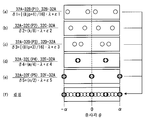
도 6은 일 실시 형태의 스크린 부재를 부분적으로 도시하는 도면이며, 도 5의 VI-VI선 단면도이다.
도 7은 일 실시 형태의 스크린 부재를 부분적으로 도시하는 도면이며, 도 5의 VII-VII선 단면도이다.
도 8은 비교예의 스크린 부재를 부분적으로 도시하는 모식도이다.
도 9는 비교예에 의한 출사광의 광로차에 대해서 설명하기 위한 모식도이다.
도 10은 비교예에 의한 회절광의 강도 분포를 도시하는 특성도이다.
도 11은 비교예에 의한 회절광의 중첩을 도시하는 특성도이다.
도 12는 일 실시 형태의 스크린 부재에 있어서의 광학 소자의 배열 형태를 도시하는 모식도이다.
도 13은 일 실시 형태에 의한 출사광의 광로차에 대해서 설명하기 위한 모식 도이다.
도 14는 일 실시 형태에 의한 회절광의 강도 분포 (a) 및 회절 피크의 중심 (b), (c)에 대해서 예시하는 특성도이다.
도 15는 일 실시 형태에 의한 회절 피크의 중심을 도시하는 특성도이다.
도 16은 일 실시 형태에 의한 회절광의 강도 분포를 도시하는 특성도이다.
도 17은 일 실시 형태에 의한 회절광의 중첩을 도시하는 특성도이다.
도 18은 도 12의 변형예를 도시하는 모식도이다.
도 19는 도 6의 변형예를 도시하는 모식도이다.
도 20은 도 6의 변형예를 도시하는 모식도이다. BRIEF DESCRIPTION OF DRAWINGS FIG. 1 is a schematic diagram showing a mounting state of a HUD device in a vehicle according to an embodiment; FIG.
2 is a perspective view showing a schematic structure of a HUD device according to one embodiment.
3 is a front view showing a display state of the HUD device according to one embodiment.
4 is a schematic diagram showing a specific configuration of the HUD device according to one embodiment.
5 is a plan view partially showing a screen member according to an embodiment.
Fig. 6 is a partial sectional view of the screen member of one embodiment, and is a cross-sectional view taken along the line VI-VI in Fig. 5;
Fig. 7 is a partial view of the screen member of one embodiment, and is a sectional view taken along the line VII-VII in Fig. 5. Fig.
8 is a schematic view partially showing a screen member of a comparative example.
9 is a schematic diagram for explaining the optical path difference of emitted light according to the comparative example.
10 is a characteristic diagram showing the intensity distribution of the diffracted light according to the comparative example.
11 is a characteristic diagram showing superposition of diffracted light according to a comparative example.
12 is a schematic diagram showing an arrangement of optical elements in a screen member according to an embodiment.
FIG. 13 is a schematic diagram for explaining the optical path difference of emitted light according to an embodiment. FIG.
Fig. 14 is a characteristic diagram exemplifying the intensity distribution (a) of the diffracted light and the centers (b) and (c) of the diffraction peak according to the embodiment.
15 is a characteristic diagram showing the center of a diffraction peak according to an embodiment.
16 is a characteristic diagram showing intensity distribution of diffracted light according to one embodiment.
17 is a characteristic diagram showing superposition of diffracted light according to one embodiment.
18 is a schematic diagram showing a modification of Fig.
19 is a schematic diagram showing a modification of Fig.
20 is a schematic diagram showing a modification of Fig.
이하, 본 개시의 일 실시 형태를 도면에 기초하여 설명한다. Hereinafter, one embodiment of the present disclosure will be described with reference to the drawings.
도 1에 도시한 바와 같이, 본 개시의 일 실시 형태에 의한 HUD 장치(100)는, 「이동체」로서의 차량(1)에 탑재되고, 인스트루먼트 패널(80) 내에 수용되어 있다. HUD 장치(100)는, 차량(1)의 「표시 부재」인 윈드 쉴드(90)에 표시 화상(71)을 투영한다. 여기서 차량(1)에 있어서, 윈드 쉴드(90)의 실내 측의 면은, 표시 화상(71)이 투영되는 투영면(91)을, 만곡하는 오목면 형상 또는 평탄한 평면 형상 등으로 형성하고 있다. 또한, 차량(1)에 있어서 윈드 쉴드(90)는, 실내 측의 면과 실외측의 면으로, 광로차를 억제하기 위한 각도 차를 갖는 것이어도 되고, 혹은 당해 광로차 억제를 위해서 증착막 내지는 필름 등을 실내 측의 면에 설치한 것이어도 된다. 1, the
표시 화상(71)이 투영면(91)에 투영되는 차량(1)에서는, 그 실내에 있어서, 투영면(91)에 의해 반사된 당해 화상(71)의 광속이 시인자의 아이 포인트(61)에 도달한다. 시인자는, 아이 포인트(61)에 도달한 광속을 지각함으로써, 윈드 쉴드(90)의 전방에 결상된 표시 화상(71)의 허상(70)을 시인한다. 이때, 도 2에 도시하는 시인자의 시인 영역(60) 내에 아이 포인트(61)가 위치함으로써, 허상(70)이 시인 가능하게 된다. In the
이상, 투영면(91)에의 표시 화상(71)의 투영에 의해 HUD 장치(100)는, 도 3에 도시한 바와 같이, 표시 화상(71)의 허상(70)을 차량(1)의 실내에서 시인 가능하도록 표시하게 된다. 또한, 허상(70)으로서는, 차량(1)의 주행 속도의 지시 표시(70a)나, 내비게이션 시스템에 의한 차량(1)의 진행 방향의 지시 표시(70b), 차량(1)에 관한 워닝 표시(70c) 등이 표시된다. As described above, by projecting the display image 71 on the
(HUD 장치의 전체적 특징) (Overall feature of HUD device)
이하, HUD 장치(100)의 전체적인 특징을 설명한다. 도 1에 도시한 바와 같이 HUD 장치(100)는, 레이저 스캐너(10), 컨트롤러(29), 스크린 부재(30) 및 광학계(40)를, 하우징(50) 내에 구비하고 있다. The overall characteristics of the
도 4에 도시한 바와 같이, 「투사기」인 레이저 스캐너(10)는, 광원부(13), 도광부(20), 미소 전기 기계 시스템(Micro Electro Mechanical Systems;MEMS)(26)을 갖고 있다. 4, the
광원부(13)는, 세개의 레이저 투사부(14, 15, 16)등으로 구성되어 있다. 각 레이저 투사부(14, 15, 16)는, 전기 접속된 컨트롤러(29)로부터의 제어 신호에 따라, 서로 다른 색상의 단일 파장 레이저광을 각각 투사한다. 구체적으로 레이저 투사부(14)는, 예를 들어 피크 파장이 600 내지 650㎚의 범위(바람직하게는 640㎚)에 나타나는 적색 레이저광을 투사한다. 레이저 투사부(15)는, 예를 들어 피크 파장이 430 내지 470㎚의 범위(바람직하게는 450㎚)에 나타나는 청색 레이저광을 투사한다. 레이저 투사부(16)는, 예를 들어 피크 파장이 490 내지 530㎚의 범위(바람직하게는 515㎚)에 나타나는 녹색의 레이저광을 투사한다. 이렇게 각 레이저 투사부(14, 15, 16)로부터 투사되는 삼색의 레이저광을 가색 혼합함으로써, 여러가지의 색의 재현이 가능하게 된다. The
도광부(20)는, 세개의 콜리메이트 렌즈(21), 다이크로익 필터(22, 23, 24) 및 집광 렌즈(25)등으로 구성되어 있다. 각 콜리메이트 렌즈(21)는, 각각 대응하는 레이저 투사부(14, 15, 16)에 대하여, 레이저광의 투사측에 예를 들어 0.5mm의 간격을 두고 배치되어 있다. 각 콜리메이트 렌즈(21)는, 대응하는 레이저 투사부(14, 15, 16)로부터의 레이저광을 굴절시킴으로써, 당해 레이저광을 평행광으로 콜리메이트한다. The
각 다이크로익 필터(22, 23, 24)는, 각각 대응하는 콜리메이트 렌즈(21)에 대하여, 각 레이저 투사부(14, 15, 16)의 투사측에 예를 들어 4㎜의 간격을 두고 배치되어 있다. 각 다이크로익 필터(22, 23, 24)는, 대응하는 콜리메이트 렌즈(21)를 통과한 레이저광 중, 특정 파장의 레이저광을 반사하고 또한 그 이외의 파장의 레이저광을 투과한다. 구체적으로는, 레이저 투사부(14)의 투사측에 배치되는 다이크로익 필터(22)는, 적색 레이저광을 투과하고, 그 이외의 색의 레이저광을 반사한다. 레이저 투사부(15)의 투사측에 배치되는 다이크로익 필터(23)는, 청색 레이저광을 반사하고, 그 이외의 색의 레이저광을 투과한다. 레이저 투사부(16)의 투사측에 배치되는 다이크로익 필터(24)는, 녹색 레이저광을 반사하고, 그 이외의 색의 레이저광을 투과한다. Each of the
여기서, 다이크로익 필터(24)에 의한 녹색 레이저광의 반사 측에는, 다이크로익 필터(23)가 예를 들어 6㎜의 간격을 두고 배치되어 있다. 또한, 다이크로익 필터(23)에 의한 청색 레이저광의 반사 측 또한 녹색 레이저광의 투과 측에는, 다이크로익 필터(22)가 예를 들어 6㎜의 간격을 두고 배치되어 있다. 또한, 다이크로익 필터(22)에 의한 적색 레이저광의 투과 측 또한 청색 레이저광 및 녹색 레이저광의 반사 측에는, 집광 렌즈(25)가 예를 들어 4㎜의 간격을 두고 배치되어 있다. 이들 배치 형태에 의해, 다이크로익 필터(22)를 투과한 적색 레이저광과, 각각 다이크로익 필터(23, 24)에 의한 반사 후에 다이크로익 필터(22)에서 반사된 청색 레이저광 및 녹색의 레이저광은, 집광 렌즈(25)에의 입사에 의해 혼색된다. Here, on the reflection side of the green laser light by the
집광 렌즈(25)는, 평면 형상의 입사면 및 볼록면 형상의 출사면을 갖는 평볼록 렌즈이다. 집광 렌즈(25)는, 입사면에 입사의 레이저광을 굴절에 의해 집속하게 한다. 그 결과, 집광 렌즈(25)를 통과한 레이저광은, MEMS(26)를 향해서 출사된다. The condenser lens 25 is a flat convex lens having a planar incident surface and a convex surface emitting surface. The condensing lens 25 causes the incident surface to focus the incident laser light by refraction. As a result, the laser light that has passed through the condenser lens 25 is emitted toward the
MEMS(26)는, 제1 주사 미러(27) 및 제2 주사 미러(28), 및 그것들 주사 미러(27, 28)의 구동부(도시 생략) 등으로 구성되어 있다. 제1 주사 미러(27)에 있어서 중심부가 예를 들어 5㎜의 간격을 두고 집광 렌즈(25)와 대향하는 면에는, 박막 형상의 반사면(27b)이 알루미늄의 금속 증착 등에 의해 형성되어 있다. 또한, 제2 주사 미러(28)에 있어서 중심부가 예를 들어 1㎜의 간격을 두고 제1 주사 미러(27)와 대향하는 면에는, 박막 형상의 반사면(28b)이 알루미늄의 금속 증착 등에 의해 형성되어 있다. MEMS(26)의 구동부는, 전기적으로 접속된 컨트롤러(29)로부터의 제어 신호에 따라, 각 주사 미러(27, 28)를 각각 회전축(27a, 28a) 주위로 개별로 회전 구동한다. The
레이저 스캐너(10)의 최종단을 구성하는 제2 주사 미러(28)의 중심부는, 스크린 부재(30)의 주사면(31)에 대하여, 예를 들어 100㎜의 간격을 두고 배치되어 있다. 이러한 배치 형태에 의해, 집광 렌즈(25)로부터 주사 미러(27, 28)에 순차 입사된 레이저광은, 반사면(27b, 28b)에 의해 순차 반사됨으로써, 주사면(31)에 투사된다. The central portion of the
컨트롤러(29)는, 프로세서 등으로 구성되는 제어 회로이다. 컨트롤러(29)는, 각 레이저 투사부(14, 15, 16)에 제어 신호를 출력함으로써, 레이저광을 단속적으로 펄스 투사한다. 그와 함께 컨트롤러(29)는, 주사 미러(27, 28)의 구동부에 제어 신호를 출력함으로써, 주사면(31)에 대한 레이저광의 투사 방향을 복수의 주사선 Ls에 따라 도 4의 화살표 방향으로 변화시킨다. 이 제어에 의해, 도 5와 같이 레이저광이 원형 스폿 형상으로 투사되는 영역 O을 주사면(31)에서 이동시킴으로써, 표시 화상(71)이 묘화된다. 즉, 레이저 스캐너(10)로부터 투사되는 레이저광은, 주사면(31)을 수평 방향 x와 수직 방향 y에 주사함으로써, 표시 화상(71)이 된다. 여기서, 예를 들어 표시 화상(71)은, 수평 방향 x로 480화소 또한 수직 방향 y로 240화소를 갖는 화상으로서, 주사면(31)에 매초 60 프레임이 형성된다. 또한, 도 2에 도시한 바와 같이 주사면(31)의 수평 방향 x는, 차량(1)의 수평 방향과 일치하고 있다. 한편, 주사면(31)의 수직 방향 y는, 도 2에 도시한 바와 같이 차량(1)의 연직 방향에 대하여 기울어져 있어도 되고, 혹은 연직 방향과 일치하고 있어도 된다. The
도 5 내지 7에 도시한 바와 같이 반사형의 스크린 부재(30)는, 수지 기재 내지는 유리 기재의 표면에 알루미늄을 증착시키는 것 등에 의해 형성되어 있다. 스크린 부재(30)는, 차량(1)에 있어서 레이저 스캐너(10)보다도 상방에 배치되어 있다(도 1, 2 참조). 스크린 부재(30)는, 마이크로 미러로서의 복수의 광학 소자(32)를, 수평 방향 x와 수직 방향 y의 격자상으로 2차원 배열하여 이루어진다. 따라서, 이하에서는, 수평 방향 x 및 수직 방향 y를 총칭하고, 배열 방향 x, y라고 칭한다. As shown in Figs. 5 to 7, the reflection
스크린 부재(30)는, 각 광학 소자(32)의 표면[구체적으로는, 뒤에 상세하게 설명하는 만곡면(33)]에 의해, 주사면(31)을 구성하고 있다. 각 광학 소자(32)의 표면은, 주사면(31)에 투사된 레이저광을 반사함으로써, 당해 레이저광을 확산시켜서 출사한다. 여기서 주사면(31)에서 레이저광이 투사되는 투사 영역 O의 직경은, 예를 들어 각 광학 소자(32)의 소자 폭 가운데 최소 소자 폭에 대하여, 그 반값 이상으로 설정된다. 또한, 각 광학 소자(32)는, 도 6, 7에 도시한 바와 같이 모두 일체물로서 형성되어 있어도 되고, 혹은 별개로 형성되어 공통 기재에 보유 지지되어 있어도 된다. The
도 1, 2에 도시한 바와 같이 광학계(40)는, 오목 거울(42) 및 그것의 구동부(도시 생략)를 갖고 있다. 오목 거울(42)은, 수지 기재 내지는 유리 기재의 표면에 알루미늄을 증착시키는 것 등에 의해, 형성되어 있다. 오목 거울(42)은, 주사면(31)에서 확산된 레이저광을 반사면(42a)에 의해 반사시킴으로써, 당해 레이저광을 투영면(91) 측으로 유도해서 표시 화상(71)을 투영한다. 즉, 오목 거울(42)은, 확산된 레이저광이 주사면(31)으로부터 유도되어 투영면(91)에까지 이르는 광로를 형성하고 있다. 여기서 반사면(42a)은, 주사면(31) 및 투영면(91)으로부터 멀어지는 방향으로 중심부가 오목해지는 오목면으로서, 매끄러운 곡면 형상으로 형성됨으로써, 표시 화상(71)을 확대해서 투영 가능하게 되어 있다. As shown in Figs. 1 and 2, the
광학계(40)의 구동부는, 전기적으로 접속된 컨트롤러(29)로부터의 제어 신호에 따라, 오목 거울(42)을 도 1의 요동 축(42b) 둘레에 요동 구동한다. 이러한 요동에 의해, 투영된 표시 화상(71)의 허상(70)의 결상 위치를 상하이동함에 따라, 시인 영역(60)도 올렸다 내렸다 한다. 여기서 시인 영역(60)의 위치는, 아이립스(62)를 고려해서 규정되어 있다. 구체적으로 아이립스(62)란, 차량(1)의 실내 중, 운전석에 착좌한 임의의 시인자를 상정했을 때에 아이 포인트(61)가 존재 가능한 공간 영역을 나타내고 있다. 따라서, 오목 거울(42)의 요동에 따라서 상하이동하는 시인 영역(60)은, 당해 요동의 범위에서는 적어도 일부가 아이립스(62) 내에 들어가도록, 상정되어 있다. The driving unit of the
또한, 광학계(40)에 대해서는, 오목 거울(42) 이외의 광학 요소를 오목 거울(42) 대신에, 또는 부가해서 설치해도 된다. 또한, 광학계(40)[오목 거울(42)]를 설치하지 않고, 각 광학 소자(32)에 의해 확산된 레이저광을, 직접 투영면(91)에 투사해도 된다. As for the
(광학 소자의 상세 특징) (Detailed feature of optical element)
이어서, 광학 소자(32)의 상세한 특징을 설명한다. Next, detailed characteristics of the
도 5 내지 7에 도시한 바와 같이 각 광학 소자(32)의 표면은, 서로 공통의 만곡 형태로서 볼록 형상으로 만곡하는 볼록 형상 만곡 형태를 나타냄으로써, 원호 볼록면 형상 등의 만곡면(33)을 형성하고 있다. 각 광학 소자(32)의 만곡면(33)은, 배열 방향 x, y와의 직교 방향 z(도 2도 참조) 중 레이저 스캐너(10) 및 광학계(40)와 마주 향하는 측으로 돌출하고, 가장 돌출된 점을 면 정점(34)으로 하고 있다. As shown in Figs. 5 to 7, the surface of each
각 배열 방향 x, y에 있어서 인접하는 광학 소자(32)끼리는, 각각의 만곡면(33)의 윤곽(외측 테두리)을 서로 겹침으로써, 상호 간에 경계(35)를 형성하고 있다. 그와 더불어 각 배열 방향 x, y에 있어서, 인접하는 광학 소자(32)끼리의 면 정점(34)간 거리로 표시되는 피크 피치 d는, 전 광학 소자(32)에 공통된 값(즉, 실질적으로 동일 값)으로 되어 있다. 또한 각 배열 방향 x, y에 있어서, 각 광학 소자(32)의 만곡면(33)의 곡률 반경은, 면 정점(34)을 통하는 종단면 상에서 공통인 값(즉, 실질적으로 동일 값)으로 되어 있다. The adjacent
여기서 각 광학 소자(32)에 관해서, 면 정점(34)으로부터 경계(35)(즉, 도 6, 7의 종단면에 있어서의 변곡점)에 이르기까지의 방향 z에 있어서의 어긋남량을, 새그량이라고 한다. 이러한 새그량을 도 6, 7에서는, 부호 SA1, SA2, SA3, SA4, SA5, SB, SC, SD, SE, SF에 의해 나타내고 있다. 또한, 인접하는 광학 소자(32, 32)에 관해서, 방향 z에 있어서의 새그량의 차, 즉 방향 z에 있어서 면 정점(34, 34)끼리가 단차 형상으로 어긋남으로써 부여되는 어긋남량을, 단차량이라고 한다. 이러한 단차량을 도 6, 7에서는, 부호 δ1, δ2, δ3, δ4, δ5에 의해 나타내고 있다. 또한, 도 6, 7에서는, 이해를 용이하게 하기 위해서, 각 새그량(SA1, SA2, SA3, SA4, SA5, SB, SC, SD, SE, SF) 및 각 단차량(δ1, δ2, δ3, δ4, δ5)을, 크게 과장해서 나타내고 있다. Here, with respect to each
이러한 각 광학 소자(32)의 만곡면(33)에 의해 레이저광을 확산해 출사시키는 스크린 부재(30)에 관해서, 본 발명자들은 예의 연구를 행해 왔다. 그 결과, 인접하는 광학 소자(32)끼리의 만곡면(33)으로부터 각각 출사된 레이저광이 서로 간섭함으로써, 출사각에 따라서 복수 차수의 회절 피크를 부여하는 강도 분포의 회절광이 발생하고, 그러한 다중 회절에 기인해서 휘도 불균일이 야기된다고 하는 지견을, 본 발명자들은 얻었다. The present inventors have conducted intensive studies on the
따라서, 먼저 도 8, 9에 도시한 바와 같이, 비교예에 관한 HUD 장치에 대해서 설명한다. 이 비교예에서는, 각 광학 소자(132)가 모두 동일 치수 설계로 되어 있다. 즉 비교예에서는, 각 광학 소자(132)에 공통의 새그량 S가 부여됨으로써, 인접하는 광학 소자(132)끼리의 단차량이 모두 실질 0으로 설정되어 있다. 이러한 비교예에 의하면, 인접하는 광학 소자(132)끼리의 만곡면(133)으로부터, 레이저광이 각각 출사각 θ(도 10 참조)로 출사되어 서로 간섭함으로써, 그것들 레이저광에 광로 길이 차 ΔL이 발생한다. 여기서 광로 길이 차 ΔL은, sinθ≒θ [rad]의 근사의 원, 전 광학 소자(132)에 공통의 피크 피치 d를 사용하여, 하기의 수식 1에 의해 표시된다. 또한, 레이저광의 파장을 λ라고 정의했을 때, 광로 길이 차 ΔL이 당해 파장 λ분 변화하는 출사각 θ의 각도 차 α(도 10 참조), 즉 회절 피크의 차수가 1변화하는 출사각 θ의 각도 차 α는, sinα≒α의 근사의 원, 피크 피치 d를 사용한 다음의 수식 2에 의해 표시된다. Therefore, first, as shown in Figs. 8 and 9, the HUD device according to the comparative example will be described. In this comparative example, all of the
(수식 1)(Equation 1)
![]()
![]()
(수식 2)(Equation 2)
![]()
![]()
이들 수식 1, 2에 기초하여, 비교예에서의 광로 길이 차 ΔL이 0, ±λ가 될 때, 즉 회절 피크의 차수가 0, ±1이 될 때의 각 배열 방향 x, y의 강도 분포를 도 10에 도시한다. 도 10에 도시한 바와 같이, 강도 분포는, 출사각 θ의 각도 차 α에 따르고 있다. 즉, 일 광학 소자(132)가 그 양측의 인접 소자(132) 사이에서 발생시키는 회절광의 회절 피크는, 0부터 ±α마다의 출사각 θ를 중심으로 발생하기 때문에, 서로 겹쳐져서 강도를 서로 강화한다. 또한, 일 광학 소자(132)가 양측 인접 소자(132) 사이에서 발생시키는 회절광의 회절 밸리는, α/2로부터 α마다의 출사각 θ과 -α/2로부터 -α마다의 출사각 θ를 중심으로 발생하기 때문에 , 서로 겹쳐도 강도를 서로 강화하기 어렵다. 또한, 회절 밸리란, 회절광의 강도 분포에 있어서 회절 피크 간의 골이 되는 부분을, 의미한다. Based on these
이상에서, 일광학 소자(132)가 양측 인접 소자(132) 사이에서 발생시키는 회절광을 배열 방향 x, y마다 중첩을 해보면, 도 11에 도시하는 강도 분포가 된다. 여기서, 배열 방향 x, y의 한쪽에 관한 도 11의 강도 분포에서는, 일광학 소자(132)가 양측 인접 소자(132) 사이에서 각각 발생시키는 회절광을 이점 쇄선 그래프로 나타내고, 그들 회절광의 중첩 결과를 실선 그래프로 나타내고 있다. 이러한 강도 분포로부터 명백해진 바와 같이, 회절 피크의 중심이 겹치는 출사각 θ(즉, 0부터 ±α마다)와, 회절 밸리의 중심이 겹치는 출사각 θ(즉, α/2로부터 α마다 및 -α/2로부터 -α마다)로, 강도 차 I가 커진다. 그러므로, 회절광을 허상(70)으로서 시인하는 시인자는, 큰 강도 차 I에 따른 휘도 불균일을 감지해버린다.In the above, when the diffracted light generated by one
다음에 본 실시 형태에 대해서, 비교예와의 차이를 상세하게 설명한다. 도 5 내지 7, 12에 도시한 바와 같이, 본 실시 형태의 각 광학 소자(32)는, 기준이 되는 복수의 기준 소자(32A)와, 각 기준 소자(32A)의 주변에 복수씩 인접하는 주변 소자(32B, 32C, 32D, 32E, 32F) 중, 어느 하나로 분류된다. 이들 기준 소자(32A) 및 그것을 둘러싸는 복수 종류의 주변 소자(32B, 32C, 32D, 32E, 32F)에 대해서는, 상이한 치수 설계로 되어 있다. 또한, 설명의 이해를 용이하게 하기 위해서 도 12에서는, 기준 소자(32A) 및 주변 소자(32B, 32C, 32D, 32E, 32F)의 배열 형태를 모식적으로 나타내고, 그것들 각 소자의 윤곽 내에 부호 말미의 알파벳만을 도시하고 있다. Next, the difference between the present embodiment and the comparative example will be described in detail. As shown in Figs. 5 to 7 and 12, each
구체적으로 배열 방향 x, y의 각각에 있어서, 서로 인접하는 기준 소자(32A)와 주변 소자(32B)의 쌍은, 제1 소자조 P1을 구성하고 있다. 이 쌍을 이루는 소자(32A, 32B) 사이에서의 단차량 δ1을 나타내기 위해서, 0 이상의 정수로서 jp를 정의하고, 1이상의 정수로서 jm을 정의하고, 레이저광의 파장을 λ라고 정의하고, -λ/32보다도 크고 또한 λ/32보다도 작은 조건을 만족하는 수치로서 ε1을 정의한다. 이들 정의 하에 있어서 단차량 δ1은, 다음의 수식 3 또는 수식 4에 의해 표시된다. 여기서 기준 소자(32A)에는, 자신의 면 정점(34)과 동일조 P1의 주변 소자(32B) 사이에서, 단차량 δ1에 대응한 새그량 SA1이 부여되어 있다. 그와 더불어 주변 소자(32B)에는, 동일조 P1의 기준 소자(32A)와의 사이에서, 단차량 δ1에 대응한 새그량 SB가 부여되어 있다. Specifically, in each of the arrangement directions x and y, the pair of the
(수식 3)(Equation 3)
![]()
![]()
(수식 4)(Equation 4)
![]()
![]()
배열 방향 x, y의 각각에 있어서, 서로 인접하는 기준 소자(32A)와 주변 소자(32C)의 쌍은, 제2 소자조 P2를 구성하고 있다. 이 쌍을 이루는 소자(32A, 32C) 사이에서의 단차량 δ2를 나타내기 위해서, 1이상의 홀수로서 k를 정의하고, 레이저광의 파장을 λ라고 정의하고, -λ/32보다도 크고 또한 λ/32보다도 작은 조건을 만족하는 수치로서 ε2를 정의한다. 이들 정의 하에 있어서 단차량 δ2는, 다음의 수식 5에 의해 표시된다. 여기서 기준 소자(32A)에는, 자신의 면 정점(34)과 동일조 P2의 주변 소자(32C) 사이에서, 단차량 δ2에 대응한 새그량 SA2가 부여되어 있다. 그와 함께 주변 소자(32C)에는, 동일조 P2의 기준 소자(32A)와의 사이에서, 단차량 δ2에 대응한 새그량 SC가 부여되어 있다. In each of the arrangement directions x and y, the pair of the
(수식 5)(Equation 5)

배열 방향 x, y의 각각에 있어서, 서로 인접하는 기준 소자(32A)와 주변 소자(32D)의 쌍은, 제3 소자조 P3을 구성하고 있다. 이 쌍을 이루는 소자(32A, 32D) 사이에서의 단차량 δ3을 나타내기 위해서, 0이상의 정수로서 lp를 정의하고, 1이상의 정수로서 lm를 정의하고, 레이저광의 파장을 λ라고 정의하고, -λ/32보다도 크고 또한 λ/32보다도 작은 조건을 만족하는 수치로서 ε3을 정의한다. 이들 정의 하에 있어서 단차량 δ3은, 다음의 수식 6 또는 수식 7에 의해 표시된다. 여기서 기준 소자(32A)에는, 자신의 면 정점(34)과 동일조 P3의 주변 소자(32D) 사이에서, 단차량 δ3에 대응한 새그량 SA3이 부여되어 있다. 그와 함께 주변 소자(32D)에는, 동일조 P3의 기준 소자(32A)와의 사이에서, 단차량 δ3에 대응한 새그량 SD가 부여되어 있다. In each of the arrangement directions x and y, the pair of the
(수식 6)(Equation 6)
![]()
![]()
(수식 7)(Equation 7)
![]()
![]()
배열 방향 x, y의 각각에 있어서, 서로 인접하는 기준 소자(32A)와 주변 소자(32E)의 쌍은, 제4 소자조 P4를 구성하고 있다. 이 쌍을 이루는 소자(32A, 32E) 사이에서의 단차량 δ4을 나타내기 위해서, 1이상의 홀수로서 m을 정의하고, 레이저광의 파장을 λ라고 정의하고, -λ/32보다도 크고 또한 λ/32보다도 작은 조건을 만족하는 수치로서 ε4을 정의한다. 이들 정의 하에 있어서 단차량 δ4는, 다음의 수식 8에 의해 표시된다. 여기서 기준 소자(32A)에는, 자신의 면 정점(34)과 동일조 P4의 주변 소자(32E) 사이에서, 단차량 δ4에 대응한 새그량 SA4가 부여되어 있다. 그와 함께 주변 소자(32E)에는, 동일조 P4의 기준 소자(32A)와의 사이에서 단차량 δ4에 대응한 새그량 SE가 부여되어 있다. In each of the arrangement directions x and y, the pair of the
(수식 8)(Equation 8)
![]()
![]()
배열 방향 x, y의 각각에 있어서, 서로 인접하는 기준 소자(32A)와 주변 소자(32F)의 쌍은, 제5 소자조 P5를 구성하고 있다. 이 쌍을 이루는 소자(32A, 32F) 시이에서의 단차량 δ5를 나타내기 위해서, 0이상의 정수로서 n을 정의하고, 레이저광의 파장을 λ라고 정의하고, -λ/32보다도 크고 또한 λ/32보다도 작은 조건을 만족하는 수치로서 ε5를 정의한다. 이들 정의 하에 있어서 단차량 δ5는, 다음의 수식 9에 의해 표시된다. 여기서 기준 소자(32A)에는, 자신의 면 정점(34)과 동일조 P5의 주변 소자(32F) 사이에서, 단차량 δ5에 대응한 새그량 SA5가 부여되어 있다. 그와 함께 주변 소자(32F)에는, 동일조 P5의 기준 소자(32A) 사이에서, 단차량 δ5에 대응한 새그량 SF가 부여되어 있다. In each of the arrangement directions x and y, the pair of the
(수식 9)(Equation 9)
![]()
![]()
여기서, i=1, 2, 3, 4, 5라고 했을 때, 소자조 Pi와 단차량 δi와 새그량 (SAi, SB, SC, SD, SE, SF) 사이의 상관 관계는, 도 13에 모식적으로 도시하는 관계가 된다. 이러한 상관 관계 아래, 수식 3 내지 9를 따르는 단차량 δi가 상이하게 해서 분류되는 복수 종류의 소자조 Pi는, 본 실시 형태에서는, 배열 방향 x, y마다 고정된 순서로 나열해 있다. 즉, 수평 방향 x에 있어서의 소자조 Pi의 병렬 순서는, 도 5, 12의 좌측으로부터 우측을 향해서 P1, P2, P3, P4, P5의 순서대로 고정되어 있다. 또한 한편, 수직 방향 y에 있어서의 소자조 Pi의 병렬 순서는, 도 5, 12의 상측에서 하측으로 향해서 P4, P1, P3, P5, P2의 순서대로 고정되어 있다. The correlation between the element group Pi, the end group δi and the new amount (SAi, SB, SC, SD, SE, SF) As shown in FIG. Under these correlations, a plurality of kinds of element tiles Pi, which are classified differently in accordance with the
이러한 고정된 병렬 순서에 의해 각 배열 방향 x, y에서는, 기준 소자(32A)와 어느 하나의 주변 소자(32B, 32C, 32D, 32E, 32F)를 교대로 배열시킨 배열 형태가, 현출되고 있다. 그와 함께, 고정된 병렬 순서에 의해 어떤 배열 방향 x, y에 있어서도, 각 주변 소자(32B, 32C, 32D, 32E, 32F)가 양측으로부터 기준 소자(32A)에 끼워져 있다. 또한, 고정된 정렬 순서에 의해, 기준 소자(32A)와 각 주변 소자(32B, 32C, 32D, 32E, 32F)의 배열 수는, 기준 소자(32A)의 5개에 대하여 각 주변 소자(32B, 32C, 32D, 32E, 32F)가 하나로 되어 있다. By this fixed parallel sequence, an arrangement in which the
또한, 본 실시 형태에 있어서 각 소자조 Pi의 기준 소자(32A)는, 도 6, 7과 같이 병렬 순서가 이웃이 되는 다른 소자조 Pi의 주변 소자(32B, 32C, 32D, 32E, 32F) 사이에서도, 각각, 단차량(δ1, δ2, δ3, δ4, δ5)을 갖고 있다. 이에 의해 각 소자조 Pi의 기준 소자(32A)는, 어떤 방향 x, y에 인접하는 주변 소자(32B, 32C, 32D, 32E, 32F) 사이에서도, 단차량 δi가 상이하다. 또한 한편으로 각 소자조 Pi의 주변 소자(32B, 32C, 32D, 32E, 32F)는, 동일 소자조 Pi의 기준 소자(32A)와의 사이에도, 병렬 순서가 이웃이 되는 다른 소자조 Pi의 기준 소자(32A)와의 사이에도, 공통의 단차량 δi를 갖고 있다. 이러한 단차량 δi에 의해, 기준 소자(32A)의 만곡면(33)의 면 정점(34)에 있어서의 스크린 부재(30)의 두께는, 인접하는 광학 소자(32) 모든 만곡면(33)의 면 정점(34)에 있어서의 스크린 부재(30)의 두께와 상이하다. 또한, 단차량 δi에 대해서는, 모두 1.2㎛ 이하로 설정함으로써, 각 주변 소자(32B, 32C, 32D, 32E, 32F)의 소자 폭을 확보하는 것이, 바람직하다. In the present embodiment, the
또한, 각 소자조 Pi의 기준 소자(32A)에 있어서, 동일 소자조 Pi를 이루는 주변 소자(32B, 32C, 32D, 32E, 32F)로부터 자신의 면 정점(34)까지의 사이의 새그량 SAi는, 각각 대응하는 단차량 δi에 따라서 상이하다. 마찬가지로, 각 소자조 Pi의 기준 소자(32A)에 있어서는, 병렬 순서가 이웃이 되는 다른 소자조 Pi의 주변 소자(32B, 32C, 32D, 32E, 32F)로부터 자신의 면 정점(34)까지의 사이에서도, 각각 대응하는 단차량 δi에 따라서 새그량 SAi가 상이하다. 본 실시 형태에서는, 이러한 새그량 SAi를 부여하도록, 기준 소자(32A)와 각 주변 소자(32B, 32C, 32D, 32E, 32F) 사이에 개재되는 경계(35)를 모두, 도 6, 7에 나타내는 선 형상으로 형성하고 있다. The new amount SAi between the
또한, 각 소자조 Pi의 주변 소자(32B, 32C, 32D, 32E, 32F)에 있어서, 동일 소자조 Pi를 이루는 기준 소자(32A)로부터 자신의 면 정점(34)까지의 사이의 새그량(SB, SC, SD, SE, SF)은, 각각 대응하는 단차량 δi에 따라서 상이하다. 그와 마찬가지로, 각 소자조 Pi의 주변 소자(32B, 32C, 32D, 32E, 32F)에 있어서, 병렬 순서가 이웃이 되는 소자조 Pi의 기준 소자(32A)로부터 자신의 면 정점(34)까지의 사이에서도, 각각 대응하는 단차량 δi에 따라서 새그량(SB, SC, SD, SE, SF)이 상이하다. 본 실시 형태에서는, 이러한 새그량(SB, SC, SD, SE, SF)이 발생하도록, 기준 소자(32A)와의 사이에 있어서의 각 주변 소자(32B, 32C, 32D, 32E, 32F)의 피크 피치 d를, 상술한 바와 같이 공통화하고 있다. In the
본 실시 형태에 있어서, 인접하는 광학 소자(32)끼리의 만곡면(33)으로부터, 레이저광이 각각 출사각 θ(도 14 참조)로 출사되어서 서로 간섭함으로써, 그들 레이저광에 광로 길이 차 ΔL이 발생한다. 여기서 광로 길이 차 ΔL은, sinθ≒θ [rad]의 근사의 원, 단차량 δi의 어느 것보다도 충분히 큰 피크 피치 d를 사용하고, 하기의 수식 10 또는 수식 11에 의해 표시된다. 구체적으로 수식 10은, 배열 방향 x, y마다, 각 주변 소자(32B, 32C, 32D, 32E, 32F)와 그 편측(예를 들어 도 6, 7의 우측)의 인접 기준 소자(32A) 사이에, 성립한다. 또한 한쪽에서 수식 11은, 배열 방향 x, y마다, 각 주변 소자(32B, 32C, 32D, 32E, 32F)와 그 반대측(예를 들어 도 6, 7의 좌측)의 인접 기준 소자(32A) 사이에, 성립한다. 또한, 광로 길이 차 ΔL이 파장 λ분 변화하는 출사각 θ의 각도 차 α(도 14 참조), 즉 회절 피크의 차수가 1변화하는 출사각 θ의 각도 차 α는, 비교예의 경우와 마찬가지로, 피크 피치 d를 사용한 다음의 수식 12에 의해 표시된다. In the present embodiment, the laser beams are emitted from the
(수식 10)(Equation 10)
![]()
![]()
(수식 11)(Equation 11)

(수식 12)(Equation 12)
![]()
![]()
또한, 복수 색의 레이저광을 레이저 스캐너(10)로부터 투사하는 본 실시 형태에서는, 수식 3 내지 9, 12를 구성하는 파장 λ는, 적어도 일색의 레이저광에 대해서 설정된다. 예를 들어 일색의 레이저광에 대해서 설정하는 경우에는, 시감도가 높은 녹색 레이저광의 피크 파장, 혹은 회절각이 큰 적색 레이저광의 피크 파장을, 파장 λ로 하는 것이 바람직하다. 또한, 2색 이상의 레이저광에 대해서 설정하는 경우에는, 그들 2색 이상의 각 피크 파장 λ마다 수식 3 내지 9를 성립시키는 것이 바람직하다. In this embodiment in which laser beams of plural colors are projected from the
상술한 수식 10, 11, 12에 기초하여, 본 실시 형태에서의 광로 길이 차 ΔL이 0, ±λ가 될 때, 즉 회절 피크의 차수가 0, ±1이 될 때의 각 배열 방향 x, y의 강도 분포는, 도 14와 같이 출사각 θ의 각도 차 α에 따르고 있다. 즉, 수식 10, 12에 따라서 각 주변 소자(32B, 32C, 32D, 32E, 32F)가 편측의 인접 기준 소자(32A) 사이에서 발생시키는 회절 피크는, 0에 대하여 2·δi·α/λ분 어긋난 0차 회절각 θ0으로부터, ±α마다의 출사각 θ를 중심으로 발생한다. 또한, 수식 11, 12을 따라서 각 주변 소자(32B, 32C, 32D, 32E, 32F)가 반대측의 인접 기준 소자(32A) 사이에서 발생시키는 회절 피크는, 0에 대하여 -2·δi·α/λ분 어긋난 0차 회절각 -θ0으로부터, ±α마다의 출사각 θ를 중심으로 발생한다. 또한, 도 14는, δ2=λ/8로 설정함으로써, 회절 피크가 θ0=α/4 및 -θ0=-α/4의 각각으로부터 ±α마다 발생하고 있는 예로서, 분도 (a)에 의해 강도 분포 또한 분도 (b), (c)에 의해 회절 피크의 중심을 나타내고 있다. 또한, 도 14의 (a)의 실선 그래프에 붙여진 포인트 a 내지 g는, 도 13에 예시한 각 광로 길이 차 ΔL을 발생하는 회절광의 방향 a 내지 g에, 각각 대응하고 있다. On the basis of the
이러한 원리로부터, 배열 방향 x, y의 각각에 있어서 주변 소자(32B, 32C, 32D)에 대해서는, 양측의 인접 기준 소자(32A) 사이에서 발생시키는 회절 피크가, 당해 양측에서 공통이 되는 단차량 δi에 따라서 도 15의 (a) 내지 (c)와 같이 어긋난다. 또한, 배열 방향 x, y의 각각에 있어서 주변 소자(32E, 32F)에 대해서는, 수식 8, 9의 ε4, ε5가 0이외의 경우, 양측의 인접 기준 소자(32A) 사이에서 발생시키는 회절 피크가, 당해 양측에서 공통이 되는 단차량 δi에 따라서 도 15의 (d), (e)와 같이 어긋난다. 이 결과 예를들면 도 14, 15의 (b)와 같이, 주변 소자(32C)가 그 편측의 인접 기준 소자(32A)와의 사이에서 발생시키는 회절 피크는, 동 주변 소자(32C)가 그 반대 측의 인접 기준 소자(32A)와의 사이에서 발생시키는 회절 밸리에, 중첩한다. From this principle, the diffraction peaks generated between the
그런데 여기까지는, 주변 소자(32B, 32C, 32D, 32E, 32F)를 중심으로 하고, 기준 소자(32A)와의 사이에 발생하는 회절광의 회절 피크를, 살펴 왔다. 이어서, 기준 소자(32A)를 중심으로 하여, 주변 소자(32B, 32C, 32D, 32E, 32F)와의 사이에 발생하는 회절광의 회절 피크를, 살펴 본다. 도 15, 16에 도시한 바와 같이, 기준 소자(32A)가 인접 주변 소자(32B, 32C, 32D, 32E, 32F)와의 사이에서 발생시키는 회절 피크는, 상이한 단차량 δi에 따른 λ/16±ε씩, 강도 분포에 있어서 서로 어긋난다. 여기서 ±ε은, λ/16로부터의 편차로서, 기준 소자(32A)의 인접 주변 소자(32B, 32C, 32D, 32E, 32F)마다, 대응하는 수식 3 내지 9의 ε1, ε2, ε3, ε4, ε5에 따라서 결정된다. 또한, 도 16 및 후술하는 도 17에서는, 설명의 이해를 용이하게 하기 위해서, ε1, ε2, ε3, ε4, ε5가 모두 0이 되는 경우, 즉 ±ε이 모두 0이 되는 경우를 나타내고 있다. Up to this point, the diffraction peaks of the diffracted light generated between the
이 결과, 예를 들어 도 15, 16과 같이, 기준 소자(32A)가 그 하나의 인접 주변 소자(32C) 사이에서 발생시키는 회절 피크는, 동 기준 소자(32A)가 그 밖의 인접 주변 소자(32B, 32D, 32E, 32F) 사이에서 발생시키는 회절 밸리에, 중첩한다. 또한, 도 15에 붙여진 a 내지 e는, 도 16에 붙여진 a 내지 e에, 각각 대응하고 있다. 또한, 도 15, 16 및 후술하는 도 17에서는, δ1에 관해서 수식 3의 경우만 또한 δ3에 관해서 수식 6의 경우만을 나타내고 있지만, δ1에 관해서 수식 4의 경우에도,δ3에 관해서 수식 7의 경우에도, 동일한 결과가 얻어진다. As a result, for example, as shown in Figs. 15 and 16, the diffraction peaks generated by the
이상에서, 기준 소자(32A)가 인접 주변 소자(32B, 32C, 32D, 32E, 32F) 사이에서 발생시키는 회절광을 배열 방향 x, y마다 도 15의 (f)와 같이 중첩을 해보면, 도 17에 나타내는 강도 분포가 된다. 여기서, 배열 방향 x, y의 한쪽에 관한 도 17의 강도 분포에서는, 기준 소자(32A)가 인접 주변 소자(32B, 32C, 32D, 32E, 32F)와의 사이에서 각각 발생시키는 회절광을 이점 쇄선 그래프로 나타내고, 그것들 회절광의 중첩 결과를 실선 그래프로 나타내고 있다. 이러한 강도 분포로부터 명백해진 바와 같이, 각 회절 피크 중심의 출사각 θ과, 그것들 중심 간의 출사각 θ로, 강도 차 I가 가급적 작아진다. 그러므로, 회절광을 허상(70)으로서 시인하는 시인자는, 그러한 작은 강도 차 I에 따라서 휘도 불균일이 느끼기 어려워진다. As described above, when the diffraction light generated by the
(작용 효과) (Action effect)
이상 설명한 본 실시 형태의 작용 효과를, 이하에 설명한다. The effects of the present embodiment described above will be described below.
본 실시 형태에 있어서 인접하는 광학 소자(32)끼리는, 공통의 볼록 형상 만곡 형태를 나타내는 표면의 만곡면(33)으로부터 레이저광을 각각 출사시키므로, 출사광의 간섭에 의해 발생하는 회절광의 강도 분포는, 출사각 θ에 따른 복수 차수의 회절 피크가 발생한다. 단, 인접하는 광학 소자(32)끼리의 사이에는, 그들 소자(32)의 각각에서 만곡면(33)의 면 정점(34)끼리를 단차 형상으로 어긋나게 이루어지는 단차량 δi가 상이하게 됨으로써, 당해 단차량 δi에 따른 출사각 θ를 중심으로 해서 회절광의 회절 피크가 발생하게 된다. Since the adjacent
따라서, 본 실시 형태에 의하면, 기준의 광학 소자(32)로 한 각 기준 소자(32A)는, 그 주변 인접의 광학 소자(32)인 주변 소자(32B, 32C, 32D, 32E, 32F)의 각각의 사이에서, 상이한 단차량 δi를 갖고 있다. 이에 의해, 기준 소자(32A)가 각 인접 주변 소자(32B, 32C, 32D, 32E, 32F)와의 사이에서 발생시키는 회절광의 회절 피크를, 상이한 단차량 δi에 따라서 어긋나게 할 수 있다. 이에 의해, 회절광을 허상으로서 시인하는 시인자가 느끼게 되는 휘도 불균일이, 억제 가능하다. Therefore, according to the present embodiment, each
또한, 본 실시 형태에서 기준 소자(32A)와 주변 소자(32B, 32C, 32D, 32E, 32F)가 교대로 2차원 배열되는 각 방향 x, y에서는, 서로 인접하는 기준 소자(32A)와 어느 하나의 주변 소자(32B, 32C, 32D, 32E, 32F)의 쌍을, 각 소자조 Pi로 한다. 여기서, 쌍을 이루는 기준 소자(32A) 및 주변 소자(32B, 32C, 32D, 32E, 32F) 사이에서의 단차량 δi를 상이하게 한 복수 종류의 소자조 Pi에 대해서는, 배열 방향 x, y마다 병렬 순서가 고정된다. 이에 의해, 배열 방향 x, y의 각각에 있어서 각 소자조 Pi의 기준 소자(32A)는, 동일 소자조 Pi를 이루는 어느 하나의 주변 소자(32B, 32C, 32D, 32E, 32F)와의 사이와, 인접한 다른 소자조 Pi를 이루는 어느 하나의 주변 소자(32B, 32C, 32D, 32E, 32F)와의 사이에, 상이한 단차량 δi가 발생할 수 있다. 그러므로, 기준 소자(32A)가 각 인접 주변 소자(32B, 32C, 32D, 32E, 32F)와의 사이에서 발생시키는 회절광에 관해서, 상이한 단차량 δi에 따른 회절 피크의 어긋남 작용을, 이차원 배열 전역에서 발휘할 수 있다. In the present embodiment, in each of the directions x and y in which the
게다가, 병렬 순서가 고정되는 배열 방향 x, y의 각각에서, 각 소자조 Pi의 주변 소자(32B, 32C, 32D, 32E, 32F)는, 동일 소자조 Pi를 이루는 기준 소자(32A)와의 사이와, 인접한 다른 소자조 Pi를 이루는 기준 소자(32A) 사이에, 공통의 단차량 δi가 발생할 수 있다. 이에 의해, 어떤 방향 x, y에 있어서도, 양측의 인접 기준 소자(32A) 사이에서 발생하는 회절광의 회절 피크가 서로 어긋나는 주변 소자로서, 적어도 소자(32B, 32C, 32D)를 현출시킬 수 있다. Further, in each of the arrangement directions x and y in which the parallel order is fixed, the
이상, 기준 소자(32A)를 중심으로 해서 본 회절 피크의 어긋남 작용과, 주변 소자(32B, 32C, 32D)를 중심으로 해서 본 회절 피크의 어긋남 작용에 의하면, 휘도 불균일의 억제 효과를 높이는 것이 가능하게 된다. As described above, it is possible to enhance the effect of suppressing the luminance unevenness by the shifting action of the diffraction peak of the
또한, 본 실시 형태에서의 제1 내지 제5 소자조 Pi의 각각에 의하면, 기준 소자(32A) 및 주변 소자(32B, 32C, 32D, 32E, 32F)의 사이에 발생하는 회절광의 회절 피크는, λ/16±ε씩 어긋난다. 그 결과, 배열 방향 x, y마다 회절광을 중첩한 강도 분포에서는, λ/16±ε의 어긋남이 발생하는 각 회절 피크 중심의 출사각 θ과, 그것들 중심 간의 출사각 θ로, 강도 차 I가 가급적 작아진다. 따라서, 회절광의 강도 차 I에 기인해서 시인자가 느끼는 휘도 불균일에 대해서, 그 억제 효과를 높이는 것이 가능하게 된다. The diffraction peaks of the diffracted light generated between the
또한, 본 실시 형태에 의하면, 복수 색의 레이저광 가운데 490 내지 530㎚의 범위에 드러나는 녹색 레이저광의 피크 파장, 즉 시감도가 높은 레이저광의 피크 파장을 수식 3 내지 9, 12의 λ로 했을 경우, 당해 파장에 관한 회절 피크를 어긋나게 할 수 있다. 이 경우, 시인자가 민감한 색에서의 휘도 불균일이, 억제 가능하게 된다. 또한, 본 실시 형태에 의하면, 복수 색의 레이저광 가운데 600 내지 650㎚의 범위에 드러나는 적색 레이저광의 피크 파장, 즉 회절각이 큰 레이저광의 피크 파장을 수식 3 내지 9, 12의 λ로 했을 경우, 당해 파장에 대해서 회절 피크를 어긋나게 할 수 있다. 이 경우, 큰 회절각 정도 쉽게 두드러지는 색으로의 휘도 불균일이 억제 가능하게 된다. Further, according to this embodiment, when the peak wavelength of the green laser light, that is, the peak wavelength of the laser light having high visibility in the range of 490 to 530 nm among the laser light of the plurality of colors is denoted by l in
또한, 본 실시 형태의 각 기준 소자(32A)에 의하면, 인접 주변 소자(32B, 32C, 32D, 32E, 32F)의 각각의 사이에는, 단차량 δi에 따른 상이한 새그량 SAi가 발생하도록, 선상의 경계(35)가 개재된다. 이에 의하면, 경계(35)에서의 레이저광 회절에 기인하는 입사광 손실이나 고스트 중첩의 발생을, 선상의 경계(35)에 의해 억제하면서, 시인자가 느끼는 휘도 불균일도, 상이한 단차량 δi에 의해 억제 가능하게 된다. Further, according to the
또한 추가해서 본 실시 형태에서는, 각 기준 소자(32A)에 인접하는 주변 소자(32B, 32C, 32D, 32E, 32F)의 각각에는, 인접 기준 소자(32A) 사이에서 공통이 되는 피크 피치 d와, 상이한 새그량(SB, SC, SD, SE, SF)을 갖고 있다. 이에 의해, 단차량 δi에 따라서 상이한 새그량 SAi가, 선상 경계(35)를 개재해서 각 기준 소자(32A)에 확실하게 발생할 수 있다. 그 결과, 단차량 δi를 상이하게 하는 구조를, 피크 피치 d의 공통화에 의해 간소하게 하면서, 시인자가 느끼는 휘도 불균일도, 당해 상이한 단차량 δi에 의해 억제 가능하게 된다. In addition, in this embodiment, each of the
(다른 실시 형태) (Other Embodiments)
이상, 본 개시의 일 실시 형태에 대해서 설명했지만, 본 개시는, 당해 실시 형태에 한정해서 해석되는 것이 아니라, 본 개시의 요지를 일탈하지 않는 범위 내에 있어서 여러가지의 실시 형태로 적용할 수 있다. Although the embodiment of the present disclosure has been described above, the present disclosure is not limited to the embodiment, but can be applied to various embodiments within the scope not deviating from the gist of the present disclosure.
구체적으로 변형예 1로서는, 도 18에 도시한 바와 같이, 주변 소자(32B, 32C, 32D, 32E, 32F) 가운데 어느 하나[도 18의 예에서는, 주변 소자(32F)]를, 스크린 부재(30)에 형성하지 않아도 된다. 이 경우, 주변 소자(32B, 32C, 32D, 32E, 32F) 가운데 스크린 부재(30)에 형성되는 소자와, 기준 소자(32A) 사이의 단차량 δi는, 수식 3 내지 9 가운데 각각 대응하는 수식을 따르고 있어도 되고, 따르고 있지 않아도 된다. 단, 이 경우에도, 각 기준 소자(32A)와, 그 인접 주변 소자 각각 사이에서, 단차량을 상이하게 하는 것이 필요해진다. Specifically, as a modified example 1, any one of the
변형예 2로서는, 도시는 하지 않지만, 주변 소자(32B, 32C, 32D, 32E, 32F)에 추가하여, 별도의 주변 소자도 스크린 부재(30)에 형성해도 된다. 이 경우, 주변 소자(32B, 32C, 32D, 32E, 32F)와 기준 소자(32A) 사이의 단차량 δi에 대해서는, 수식 3 내지 9를 따르고 있어도 되고, 따르지 않고 있어도 된다. 단, 이 경우에도, 각 기준 소자(32A)와, 소자(32B, 32C, 32D, 32E, 32F) 및 추가 소자를 포함하는 인접 주변 소자 각각의 사이에서, 단차량을 상이하게 하는 것이 필요해진다. As a modified example 2, although not shown, a separate peripheral element may be formed in the
변형예 3으로서는, 도 18에 도시한 바와 같이 소자조의 병렬 순서를, 각 배열 방향 x, y마다 고정하는 대신, 각 배열 방향 x, y에 따르는 열마다 변화시켜도 된다. 예를 들어 도 18에서는, 제1 소자조 P1 및 제3 소자조 P3이 교대로 배열하는 열과, 제2 소자조 P2 및 제4 소자조 P4가 교대로 배열하는 열이, 각 배열 방향 x, y에 따라 형성되어 있다. As a modification example 3, the parallel arrangement of element tiles may be changed for each column along each arrangement direction x, y instead of being fixed for each arrangement direction x, y as shown in Fig. For example, in Fig. 18, the rows in which the first element group P1 and the third element group P3 are alternately arranged and the rows in which the second element group P2 and the fourth element group P4 are alternately arranged are arranged in the array directions x, y As shown in FIG.
변형예 4로서는, 볼록 형상으로 만곡하는 볼록조 만곡 형태의 만곡면(33) 대신에, 도 19에 도시한 바와 같은 원호 오목면 형상 등, 오목 형상으로 만곡하는 오목 형상 만곡 형태의 만곡면(1033)을, 광학 소자(1032)의 표면에 형성해도 된다. 이 경우, 각 광학 소자(1032) 표면에 있어서 만곡면(1033)을, 방향 x, y와의 직교 방향 z 중에 레이저 스캐너(10) 및 광학계(40)와는 반대측으로 요함시키고, 최요함점을 면정점(1034)으로 한다. 또한, 도 19에 도시한 바와 같이 변형예 4에서는, 이들 이외의 구성으로서, 상술한 실시 형태와 동일한 구성이 채용된다. As a modified example 4, instead of the
변형예 5로서는, 주사면(31)에 투사된 레이저광을 투과함으로써, 당해 레이저광을 확산시켜서 출사하는 만곡면(33, 1033)을, 마이크로렌즈로서의 광학 소자(32, 1032)의 표면에 형성해도 된다. 또한, 변형예 6로서는, 도 20에 도시한 바와 같이, 기준 소자(32A)와 각 주변 소자(32B, 32C, 32D, 32E, 32F)를, 단차면 형상의 경계(35)를 개재하여 인접시켜도 된다. 이 경우, 기준 소자(32A)에 대한 주변 소자끼리의 새그량에 대해서는, 상이하게 해도 되고, 공통으로 해도 된다. In modified example 5, the
변형예 7로서는, 동일한 광학 소자(32, 1032)에 대하여, 수평 방향 x와 수직 방향 y로 상이한 곡률 반경을 설정해도 된다. 또한, 변형예 8로서는, 인접하는 광학 소자(32, 1032)끼리로, 상이한 곡률 반경을 설정해도 된다. As
변형예 9로서는, 「투사기」인 레이저 스캐너(10)의 MEMS(26)로서, 2축 주위에 회전 가능한 하나의 주사 미러를 채용해도 된다. 또한, 변형예 10으로서는, 차량(1)의 투영면(91)을 형성하는 「표시 부재」에 윈드 쉴드(90) 이외의 요소를 채용해도 되고, 예를 들어 윈드 쉴드(90)의 실내 측의 면에 부착한 또는 윈드 쉴드(90)와는 별개로 형성된 컴바이너 등을, 채용해도 된다. 또한, 변형예 11로서는, 차량(1) 이외의 선박 또는 비행기 등의 각종 이동체(수송 기기)에, 본 개시를 적용해도 된다.As the modified example 9, one scanning mirror which can rotate around two axes may be employed as the
Claims (8)
상기 표시 화상이 되는 레이저광을 투사하는 투사기(10)와,
격자상으로 배열되는 복수의 광학 소자(32, 1032)를 갖고,
상기 투사기로부터 상기 광학 소자에 입사되는 상기 레이저광을 확산해서 상기 투영면 측으로 유도하는 스크린 부재(30)를 구비하고,
각 상기 광학 소자는, 볼록 형상 만곡 및 오목 형상 만곡 중 공통의 만곡 형태를 나타내는 만곡면(33, 1033)을 표면에 형성하고, 당해 만곡면에서 상기 투영면 측에 출사시키는 상기 레이저광을 확산하고,
각 상기 광학 소자는, 기준이 되는 복수의 기준 소자(32A)와, 각 상기 기준 소자의 주변에 인접하는 복수의 주변 소자(32B, 32C, 32D, 32E, 32F)를 갖고,
각 상기 기준 소자와, 인접하는 상기 주변 소자의 각각은, 상기 만곡면의 면 정점(34, 1034)끼리가 단차 형상으로 어긋나 있고,
각 상기 기준 소자와, 인접하는 상기 주변 소자의 각각의 사이에 있어서의 단차량(δi, δ1, δ2, δ3, δ4, δ5)은, 상이하게 되어 있는 헤드업 디스플레이 장치. A head-up display device for projecting a display image (71) onto a projection plane (91) of a moving object (1) to visually display a virtual image (70)
A projector (10) for projecting a laser beam which becomes the display image,
And a plurality of optical elements (32, 1032) arranged in a lattice pattern,
And a screen member (30) for diffusing the laser light incident on the optical element from the projector and guiding the laser light to the projection plane side,
Each of the optical elements is provided with curved surfaces (33, 1033) having a common curved shape among a convex curved shape and a concave curved shape on a surface thereof, and diffuses the laser beam emitted from the curved surface toward the projection surface side,
Each of the optical elements has a plurality of reference elements 32A serving as a reference and a plurality of peripheral elements 32B, 32C, 32D, 32E, and 32F adjacent to the periphery of each of the reference elements,
Each of the reference elements and each of the adjacent peripheral elements is such that the plane vertices (34, 1034) of the curved surface are shifted in a stepped shape,
The stepped devices (? I,? 1,? 2,? 3,? 4,? 5) between the reference devices and the adjacent peripheral devices are different from each other.
쌍을 이루는 상기 기준 소자 및 상기 주변 소자 사이에서의 상기 단차량이 상이한 복수 종류의 상기 소자조(Pi, P1, P2, P3, P4, P5)는, 상기 배열 방향마다 병렬 순서가 고정되는, 헤드업 디스플레이 장치. The apparatus according to claim 1, further comprising an element trench in which the reference element and the peripheral element are alternately arranged in two dimensions,
(P 1, P 2, P 3, P 4, and P 5) having a plurality of different types of stages between the reference element and the peripheral element forming a pair are arranged in parallel in the arrangement direction. Up display device.
0이상의 정수로서 jp, lp, n을 정의하고, 1이상의 정수로서 jm, lm을 정의하고, 1이상의 홀수로서 k, m을 정의하고, 상기 레이저광의 파장을 λ라고 정의하고, -λ/32보다도 크고 또한 λ/32보다도 작은 조건을 만족하는 수치로서 ε1, ε2, ε3, ε4, ε5를 정의했을 때, 각 상기 소자조는,
쌍을 이루는 상기 기준 소자 및 상기 주변 소자(32B) 사이에서의 상기 단차량(δ1)이 수식 {(8jp+1)/16}·λ+ε1, 또는 수식 {(8jm-1)/16}·λ+ε1로 표시되는 제1 소자조(P1)와,
쌍을 이루는 상기 기준 소자 및 상기 주변 소자(32C) 사이에서의 상기 단차량(δ2)이 수식(k/8)·λ+ε2로 표시되는 제2 소자조(P2)와,
쌍을 이루는 상기 기준 소자 및 상기 주변 소자(32D) 사이에서의 상기 단차량(δ3)이 수식 {(8lp+3)/16}·λ+ε3, 또는 수식 {(8lm-3)/16}·λ+ε3으로 표시되는 제3 소자조(P3)와,
쌍을 이루는 상기 기준 소자 및 상기 주변 소자(32E) 사이에서의 상기 단차량(δ4)이 수식(m/4)·λ+ε4로 표시되는 제4 소자조(P4)와,
쌍을 이루는 상기 기준 소자 및 상기 주변 소자(32F) 사이에서의 상기 단차량(δ5)이 수식(n/2)·λ+ε5로 표시되는 제5 소자조(P5)를 구비하는, 헤드업 디스플레이 장치. The optical device according to claim 2, wherein each of the optical elements diffuses and emits the laser light by reflection on the curved surface,
Wherein jp and lp are defined as integers of 0 or more, jm and lm are defined as integers of 1 or more, k and m are defined as an odd number of 1 or more, the wavelength of the laser light is defined as? When defining ε1, ε2, ε3, ε4, and ε5 as numerical values that are large and smaller than λ / 32,
(8j + 1) / 16} 了 + ε1 or the equation {(8jm-1) / 16} between the reference element and the peripheral element (32B) a first element group P1 denoted by? +? 1,
A second element group P2 in which the stepped vehicle? 2 between the pair of reference elements and the peripheral element 32C is expressed by the equation (k / 8)? +? 2,
(8lp + 3) / 16} 了 + 竜 3 or the equation (8lm-3) / 16} between the reference element and the peripheral element (32D) a third element group P3 represented by? +? 3,
The fourth element group P4 in which the stepped vehicle? 4 between the reference element and the peripheral element 32E forming a pair is expressed by the equation (m / 4)? +? 4,
Wherein the stepped vehicle (? 5) between the pair of reference elements and the peripheral element (32F) comprises a fifth element set (P5) represented by the equation (n / 2) Device.
상기 녹색 레이저광의 피크 파장을 상기 λ로 하는, 헤드업 디스플레이 장치. The projector according to claim 3, wherein the projector projects the laser light of a plurality of colors including a green laser light whose peak wavelength is in a range of 490 to 530 nm,
And a peak wavelength of the green laser light is set to be lambda.
상기 적색 레이저광의 피크 파장을 상기 λ로 하는, 헤드업 디스플레이 장치. The projector according to claim 3, wherein the projector projects the laser light of a plurality of colors including red laser light whose peak wavelength is in the range of 600 to 650 nm,
And the peak wavelength of the red laser light is set to be lambda.
2. The head-up display device according to claim 1, further comprising four peripheral elements adjacent to each other in the periphery of each of the reference elements.
Applications Claiming Priority (3)
| Application Number | Priority Date | Filing Date | Title |
|---|---|---|---|
| JPJP-P-2013-153901 | 2013-07-24 | ||
| JP2013153901A JP6213010B2 (en) | 2013-07-24 | 2013-07-24 | Head-up display device |
| PCT/JP2014/003839 WO2015011913A1 (en) | 2013-07-24 | 2014-07-22 | Head-up display device |
Publications (2)
| Publication Number | Publication Date |
|---|---|
| KR20160019965A KR20160019965A (en) | 2016-02-22 |
| KR101848186B1 true KR101848186B1 (en) | 2018-04-11 |
Family
ID=52392977
Family Applications (1)
| Application Number | Title | Priority Date | Filing Date |
|---|---|---|---|
| KR1020167001468A KR101848186B1 (en) | 2013-07-24 | 2014-07-22 | Head-up display device |
Country Status (6)
| Country | Link |
|---|---|
| US (1) | US9835774B2 (en) |
| JP (1) | JP6213010B2 (en) |
| KR (1) | KR101848186B1 (en) |
| CN (1) | CN105408804B (en) |
| DE (1) | DE112014003428T5 (en) |
| WO (1) | WO2015011913A1 (en) |
Families Citing this family (16)
| Publication number | Priority date | Publication date | Assignee | Title |
|---|---|---|---|---|
| JP6172400B2 (en) | 2014-09-03 | 2017-08-02 | 三菱電機株式会社 | Image display device |
| JP6455230B2 (en) * | 2015-03-02 | 2019-01-23 | 株式会社デンソー | Head-up display system |
| US10761323B2 (en) * | 2015-03-04 | 2020-09-01 | Nippon Seiki Co., Ltd. | Lens array and image projection device |
| JP6776534B2 (en) * | 2016-01-05 | 2020-10-28 | 日本精機株式会社 | Lens array and head-up display |
| US11294175B2 (en) | 2016-10-05 | 2022-04-05 | Lg Innotek Co., Ltd. | Head up display device |
| CN108427192A (en) * | 2017-02-13 | 2018-08-21 | 怡利电子工业股份有限公司 | Narrow angle diffusion sheet, which comes back, shows equipment |
| WO2019146423A1 (en) * | 2018-01-25 | 2019-08-01 | 富士フイルム株式会社 | Projected image display member, windshield glass, and head-up display system |
| JP2019158991A (en) | 2018-03-09 | 2019-09-19 | 株式会社リコー | Display device, display system, and mobile body |
| JP7058912B2 (en) * | 2018-03-19 | 2022-04-25 | 矢崎総業株式会社 | Head-up display device |
| WO2020071053A1 (en) * | 2018-10-05 | 2020-04-09 | Ricoh Company, Ltd. | Optical element, display device, display system, and mobile object |
| JP2020071305A (en) * | 2018-10-30 | 2020-05-07 | セイコーエプソン株式会社 | Head-mounted display device |
| TWI676823B (en) * | 2018-12-26 | 2019-11-11 | 中強光電股份有限公司 | Head-up display apparatus |
| JP7472629B2 (en) | 2020-04-28 | 2024-04-23 | 船井電機株式会社 | Light projector and mobile light projector |
| JP2021174739A (en) | 2020-04-30 | 2021-11-01 | 船井電機株式会社 | Light projection device and light projection device for vehicle |
| US20220163919A1 (en) * | 2020-11-23 | 2022-05-26 | GM Global Technology Operations LLC | Micromirror pixel design to eliminate intensity artifacts in holographic displays |
| WO2024004289A1 (en) * | 2022-06-29 | 2024-01-04 | パナソニックIpマネジメント株式会社 | Optical system and image display device |
Citations (4)
| Publication number | Priority date | Publication date | Assignee | Title |
|---|---|---|---|---|
| JP2003035808A (en) * | 2001-07-23 | 2003-02-07 | Minolta Co Ltd | Diffraction grating, polarization separating element and liquid crystal projector |
| JP2005181460A (en) | 2003-12-16 | 2005-07-07 | Seiko Epson Corp | Substrate with concave portion for microlens, microlens substrate, transmission type screen, rear-type projector and method for manufacturing substrate with concave portion |
| JP2010151902A (en) | 2008-12-24 | 2010-07-08 | Seiko Epson Corp | Screen |
| JP2010262264A (en) | 2009-04-10 | 2010-11-18 | Seiko Epson Corp | Reflective screen, projection system, front projection television, and method for manufacturing reflective screen |
Family Cites Families (10)
| Publication number | Priority date | Publication date | Assignee | Title |
|---|---|---|---|---|
| JPH07270711A (en) * | 1994-03-30 | 1995-10-20 | Canon Inc | Information display device |
| JP4089371B2 (en) * | 2002-09-24 | 2008-05-28 | セイコーエプソン株式会社 | Transmissive screen and rear projector |
| WO2008114502A1 (en) * | 2007-03-19 | 2008-09-25 | Panasonic Corporation | Laser illuminating device and image display device |
| JP5075595B2 (en) | 2007-11-26 | 2012-11-21 | 株式会社東芝 | Display device and moving body using the same |
| JP2010145746A (en) | 2008-12-18 | 2010-07-01 | Equos Research Co Ltd | Head-up display device |
| JP5392276B2 (en) | 2011-02-03 | 2014-01-22 | 株式会社デンソー | Virtual image display device |
| US8422137B2 (en) | 2011-02-28 | 2013-04-16 | Pioneer Corporation | Optical element, head-up display and method for producing optical element |
| JP5344069B2 (en) * | 2011-08-29 | 2013-11-20 | 株式会社デンソー | Head-up display device |
| JP5594272B2 (en) * | 2011-10-14 | 2014-09-24 | 株式会社デンソー | Head-up display device |
| WO2014180509A1 (en) * | 2013-05-10 | 2014-11-13 | Lemoptix Sa | A projection device |
-
2013
- 2013-07-24 JP JP2013153901A patent/JP6213010B2/en active Active
-
2014
- 2014-07-22 DE DE112014003428.2T patent/DE112014003428T5/en not_active Withdrawn
- 2014-07-22 US US14/906,275 patent/US9835774B2/en not_active Expired - Fee Related
- 2014-07-22 WO PCT/JP2014/003839 patent/WO2015011913A1/en active Application Filing
- 2014-07-22 KR KR1020167001468A patent/KR101848186B1/en active IP Right Grant
- 2014-07-22 CN CN201480041429.3A patent/CN105408804B/en not_active Expired - Fee Related
Patent Citations (4)
| Publication number | Priority date | Publication date | Assignee | Title |
|---|---|---|---|---|
| JP2003035808A (en) * | 2001-07-23 | 2003-02-07 | Minolta Co Ltd | Diffraction grating, polarization separating element and liquid crystal projector |
| JP2005181460A (en) | 2003-12-16 | 2005-07-07 | Seiko Epson Corp | Substrate with concave portion for microlens, microlens substrate, transmission type screen, rear-type projector and method for manufacturing substrate with concave portion |
| JP2010151902A (en) | 2008-12-24 | 2010-07-08 | Seiko Epson Corp | Screen |
| JP2010262264A (en) | 2009-04-10 | 2010-11-18 | Seiko Epson Corp | Reflective screen, projection system, front projection television, and method for manufacturing reflective screen |
Also Published As
| Publication number | Publication date |
|---|---|
| KR20160019965A (en) | 2016-02-22 |
| JP2015025874A (en) | 2015-02-05 |
| DE112014003428T5 (en) | 2016-04-28 |
| US9835774B2 (en) | 2017-12-05 |
| CN105408804B (en) | 2018-05-29 |
| US20160170099A1 (en) | 2016-06-16 |
| CN105408804A (en) | 2016-03-16 |
| JP6213010B2 (en) | 2017-10-18 |
| WO2015011913A1 (en) | 2015-01-29 |
Similar Documents
| Publication | Publication Date | Title |
|---|---|---|
| KR101848186B1 (en) | Head-up display device | |
| US9395541B2 (en) | Head-up display apparatus | |
| KR101746322B1 (en) | Head-up display device | |
| KR101741938B1 (en) | Head-up display device | |
| JP5344069B2 (en) | Head-up display device | |
| JP5310810B2 (en) | Head-up display device | |
| JP6237249B2 (en) | Illumination lens, illumination unit, and head-up display device | |
| KR101643837B1 (en) | Screen member and heads-up display apparatus | |
| JP6579212B2 (en) | Head-up display device | |
| US20170160543A1 (en) | Scanning projector transmissive screen, and scanning projector system | |
| JP6056680B2 (en) | Head-up display device | |
| JP2021096284A (en) | Image display device | |
| WO2017145558A1 (en) | Head-up display device | |
| JP6460185B2 (en) | Illumination lens, illumination unit, and head-up display device | |
| JP2022129523A (en) | Image projector |
Legal Events
| Date | Code | Title | Description |
|---|---|---|---|
| A201 | Request for examination | ||
| E902 | Notification of reason for refusal | ||
| E701 | Decision to grant or registration of patent right | ||
| GRNT | Written decision to grant |