KR101839552B1 - Apparatus for temporary attachment removal of nuclear power plants - Google Patents
Apparatus for temporary attachment removal of nuclear power plants Download PDFInfo
- Publication number
- KR101839552B1 KR101839552B1 KR1020170089562A KR20170089562A KR101839552B1 KR 101839552 B1 KR101839552 B1 KR 101839552B1 KR 1020170089562 A KR1020170089562 A KR 1020170089562A KR 20170089562 A KR20170089562 A KR 20170089562A KR 101839552 B1 KR101839552 B1 KR 101839552B1
- Authority
- KR
- South Korea
- Prior art keywords
- rail
- moving
- frame
- liner plate
- vertical
- Prior art date
- Legal status (The legal status is an assumption and is not a legal conclusion. Google has not performed a legal analysis and makes no representation as to the accuracy of the status listed.)
- Active
Links
Images


Classifications
-
- G—PHYSICS
- G21—NUCLEAR PHYSICS; NUCLEAR ENGINEERING
- G21C—NUCLEAR REACTORS
- G21C13/00—Pressure vessels; Containment vessels; Containment in general
- G21C13/02—Details
-
- E—FIXED CONSTRUCTIONS
- E04—BUILDING
- E04G—SCAFFOLDING; FORMS; SHUTTERING; BUILDING IMPLEMENTS OR AIDS, OR THEIR USE; HANDLING BUILDING MATERIALS ON THE SITE; REPAIRING, BREAKING-UP OR OTHER WORK ON EXISTING BUILDINGS
- E04G21/00—Preparing, conveying, or working-up building materials or building elements in situ; Other devices or measures for constructional work
-
- G21Y2002/103—
-
- G21Y2002/20—
-
- G21Y2002/501—
-
- G21Y2004/20—
-
- G21Y2004/501—
-
- Y—GENERAL TAGGING OF NEW TECHNOLOGICAL DEVELOPMENTS; GENERAL TAGGING OF CROSS-SECTIONAL TECHNOLOGIES SPANNING OVER SEVERAL SECTIONS OF THE IPC; TECHNICAL SUBJECTS COVERED BY FORMER USPC CROSS-REFERENCE ART COLLECTIONS [XRACs] AND DIGESTS
- Y02—TECHNOLOGIES OR APPLICATIONS FOR MITIGATION OR ADAPTATION AGAINST CLIMATE CHANGE
- Y02E—REDUCTION OF GREENHOUSE GAS [GHG] EMISSIONS, RELATED TO ENERGY GENERATION, TRANSMISSION OR DISTRIBUTION
- Y02E30/00—Energy generation of nuclear origin
- Y02E30/30—Nuclear fission reactors
Landscapes
- Engineering & Computer Science (AREA)
- Architecture (AREA)
- Physics & Mathematics (AREA)
- Mechanical Engineering (AREA)
- Civil Engineering (AREA)
- Structural Engineering (AREA)
- Plasma & Fusion (AREA)
- General Engineering & Computer Science (AREA)
- High Energy & Nuclear Physics (AREA)
- Working Measures On Existing Buildindgs (AREA)
Abstract
본 발명은 원자로 격납건물의 외벽 내측면에 위치하는 라이너플레이트에 부착된 임시부착물을 제거하는 장치에 관한 것으로, 상기 라이너플레이트와 격납건물 내부공간에 설치된 내부구조물과의 사이 공간에 투입되어 상기 임시부착물을 제거하고, 상기 내부구조물의 상기 라이너플레이트와 마주하는 면을 연마할 수 있도록 된 원자로 격납건물의 임시부착물 제거장치에 관한 것이다.
본 발명의 원자로 격납건물의 임시부착물 제거장치는, 지면에 지지되는 하부프레임(110)과, 상기 하부프레임(110)의 좌·우 양측에 일정높이로 수직으로 형성된 수직프레임(120)과, 상기 수직프레임(120)의 상단부에 형성된 상부프레임(130)으로 구성된 프레임부(100); 상기 수직프레임(120)의 길이방향을 따라 상방 또는 하방으로 이동되게 설치된 상하이동부(200); 상기 상하이동부(200)의 일측에 설치되어 전방 또는 후방으로 이동되는 전후이동부(300); 상기 전후이동부(300)의 일측에 설치되어 레일이송수단(410)에 의해 좌측 또는 우측으로 이송되며, 만곡된 형상의 호형으로 형성되어 길이방향으로 결합되는 다수개의 단위레일(420)과, 상기 다수개의 단위레일(420)의 길이방향을 따라 설치된 동력전달축(430)으로 구성된 만곡레일부(400); 상기 만곡레일부(400)의 일측 끝단에 원자로 격납건물의 라이너플레이트에 부착된 임시부착물을 제거하기 위해 설치되는 절삭날(510)을 갖는 절삭툴(500); 상기 만곡레일부(400)의 타측 끝단에 설치되며 상기 동력전달축(430)과 연결되어 상기 동력전달축(430)과 연결된 절삭날(510)을 회전시키는 구동모터부(600);로 이루어진 것을 특징으로 한다.The present invention relates to an apparatus for removing a temporary deposit adhered to a liner plate located on an inner wall of an outer wall of a nuclear reactor containment building and is inserted into a space between the liner plate and an inner structure installed in a space inside the containment building, And a surface of the internal structure facing the liner plate can be polished. 2. Description of the Related Art
The apparatus includes a lower frame (110) supported on the ground, a vertical frame (120) vertically formed on both left and right sides of the lower frame (110) at a predetermined height, A frame part 100 composed of an upper frame 130 formed at an upper end of the vertical frame 120; A vertical moving part 200 installed to be moved upward or downward along the longitudinal direction of the vertical frame 120; A forward / backward moving part 300 installed on one side of the up / down moving part 200 and moving forward or backward; A plurality of unit rails 420 installed at one side of the front and rear moving unit 300 and being conveyed to the left or right by the rail conveying means 410 and formed in a curved arc shape and coupled in the longitudinal direction, A curved rail part 400 constituted by a power transmission shaft 430 installed along the longitudinal direction of the unit rail 420; A cutting tool (500) having a cutting edge (510) installed at one end of the curved rail part (400) to remove a temporary attachment attached to a liner plate of a nuclear reactor containment building; And a driving motor part 600 installed at the other end of the curved rail part 400 and connected to the power transmission shaft 430 to rotate a cutting edge 510 connected to the power transmission shaft 430 .
Description
본 발명은 원자로 격납건물의 외벽 내측면에 위치하는 라이너플레이트에 부착된 임시부착물을 제거하는 장치에 관한 것으로, 상기 라이너플레이트와 격납건물 내부공간에 설치된 내부구조물과의 사이 공간에 투입되어 상기 임시부착물을 제거하고, 상기 내부구조물의 상기 라이너플레이트와 마주하는 면을 연마할 수 있도록 된 원자로 격납건물의 임시부착물 제거장치에 관한 것이다.The present invention relates to an apparatus for removing a temporary deposit adhered to a liner plate located on an inner wall of an outer wall of a nuclear reactor containment building and is inserted into a space between the liner plate and an inner structure installed in a space inside the containment building, And a surface of the internal structure facing the liner plate can be polished. 2. Description of the Related Art
원자로 격납건물이란, 원자로 사고시 관리되는 구역을 넘어서 허용된 양을 초과하는 방사성 물질이 대기중으로 배출되는 것을 방지하는 건물이다.A nuclear reactor containment is a building that prevents radioactive materials from being released into the atmosphere beyond the permitted amount beyond the area managed in reactor accidents.
상기 원자로 격납건물은 핵반응조와 증기발생기와 연료이송관 등 원자로의 주기기가 배치되는 밀폐건물로서, 일반적으로 원자로 격납건물은 콘크리트구조물로 기초부 상에 반구형상의 돔 상부를 갖는 외벽을 갖추고, 그 내부에 별도의 공간을 이루어 증기발생기, 연료이송관 등과 같은 설비기기가 배치되는 내부구조물들이 구비된다.The reactor containment building is an enclosed building in which a nuclear reactor vessel, a steam generator, and a fuel feed line are disposed. In general, a nuclear reactor containment structure is a concrete structure having an outer wall having a hemispherical dome upper portion on the base portion, An internal structure in which equipment such as a steam generator, a fuel transfer pipe, and the like are disposed is provided.
상기와 같은 격납건물의 외벽은 일반적으로 1.2m 두께의 콘크리트로 형성되며, 그 외벽의 내측면에는 추가 방호벽의 역할과 외벽을 형성할 시에 거푸집으로서의 역할을 겸하는 약 6mm 두께의 철판인 라이너플레이트가 설치되어 있다.The outer wall of the above-mentioned containment building is generally made of concrete having a thickness of 1.2 m, and a liner plate, which is an iron plate having a thickness of about 6 mm, serves as an additional barrier wall on the inner side of the outer wall and serves as a mold when forming the outer wall Is installed.
일반적으로 상기 라이너플레이트는 CLP(Containment Liner Plate)라고도 불리우며, 상기 라이너플레이트는 돔형상의 지붕에 위치되는 돔라이너와, 벽면에 위치되는 셀 라이너와, 하부 지반으로 매설하여 설치되는 캐비티 라이너로 이루어진다.Generally, the liner plate is also called CLP (Containment Liner Plate), and the liner plate is composed of a dome liner positioned on a dome-shaped roof, a cell liner located on a wall surface, and a cavity liner embedded in the lower ground.
상기와 같이 라이너플레이트 중 벽면에 위치되는 라이너플레이트를 세워 설치함에 있어서, 강재로 된 라이너플레이트는 무게로 인해 작업자의 힘만으로는 설치가 불가능하며, 따라서 라이너플레이트를 설치하기 위해서는 별도의 작업기를 사용하게 된다.As described above, when the liner plate located on the wall surface of the liner plate is installed upright, the liner plate made of the steel can not be installed only by the force of the operator due to its weight. Therefore, a separate working machine is used for installing the liner plate .
이때, 라이너플레이트는 돌출부가 없는 판형으로 형성되어 있으므로 상기 작업기를 사용하여 들어올리기 위해서는 상기 라이너플레이트에 임시부착물을 용접 등의 방법으로 부착시키게 된다.At this time, since the liner plate is formed in a plate shape having no protrusion, a temporary attachment is attached to the liner plate by welding or the like in order to lift the liner plate using the working machine.
이러한 임시부착물이 형성된 라이너플레이트를 세워 설치한 후, 격납건물의 외벽을 타설하고, 상기 임시부착물을 제거하지 않은 상태에서 격납건물 내부에 내부구조물을 배치 또는 형성하였다.After the liner plate on which the temporary attachment is formed is installed upright, an outer wall of the containment building is laid, and the inner structure is arranged or formed inside the containment building without removing the temporary attachment.
그러나 상기 내부구조물 중에는 상기 라이너플레이트와 약 5cm 내지 10cm 내외의 협소한 간격을 두고 설치되는 내부구조물이 있고, 한번 설치된 내부구조물은 그 위치의 변경이 불가능하며, 상기와 같이 라이너플레이트에 부착된 임시부착물은 시간이 지남에 따라 협소한 상기 라이너플레이트와 내부구조물의 간격 사이에서 부식되어 상기 라이너플레이트를 손상시키거나 콘크리트로 형성된 상기 내부구조물에 균열을 일으키는 문제점이 발생하였다.However, in the internal structure, there is an internal structure provided at a narrow gap of about 5 cm to 10 cm with the liner plate, and the position of the internal structure once installed can not be changed. As described above, There is a problem that the liner plate is corroded between the narrow liner plate and the interval of the internal structure over time to damage the liner plate or cause cracks in the internal structure formed of concrete.
그러나 상기 라이너플레이트와 내부구조물의 협소한 간격의 사이 공간으로 진입하여 상기 임시부착물을 제거하는 것은 현재까지 매우 어려움을 겪고 있으며, 상기 임시부착물의 부식으로 인한 라이너플레이트 및 내부구조물의 손상이 발생하게 되면 심각한 방사능 유출의 사고가 발생할 수 있으므로 이에 따른 대책 마련이 시급한 실정이다.However, it has been very difficult to enter the space between the liner plate and the inner structure to remove the temporary deposit, and if the liner plate and the inner structure are damaged due to the corrosion of the temporary deposit Serious radioactive spillage accidents may occur, so it is urgent to take measures accordingly.
본 발명의 목적은 원자로 격납건물의 외벽 내측면에 위치하는 라이너플레이트와 내부구조물과의 협소한 사이 공간에 삽입되어 임시부착물을 절삭 또는 연마하여 제거하고, 상기 라이너플레이트와 마주하는 내부구조물의 콘크리트 간섭부 역시 연마하여 제거할 수 있는 원자로 격납건물의 임시부착물 제거장치를 제공하는 데 있다.SUMMARY OF THE INVENTION It is an object of the present invention to provide a method of manufacturing a reactor containment structure that is inserted into a narrow space between a liner plate and an inner structure located on an inner wall of an outer wall of a nuclear reactor containment building to cut or abrade the temporary attachment, The present invention also provides a temporary deposit removing apparatus for a nuclear reactor containment which can be polished and removed.
상기한 목적을 달성하기 위한 본 발명의 원자로 격납건물의 임시부착물 제거장치는, 지면에 지지되는 하부프레임(110)과, 상기 하부프레임(110)의 좌·우 양측에 일정높이로 수직으로 형성된 수직프레임(120)과, 상기 수직프레임(120)의 상단부에 형성된 상부프레임(130)으로 구성된 프레임부(100); 상기 수직프레임(120)의 길이방향을 따라 상방 또는 하방으로 이동되게 설치된 상하이동부(200); 상기 상하이동부(200)의 일측에 설치되어 전방 또는 후방으로 이동되는 전후이동부(300); 상기 전후이동부(300)의 일측에 설치되어 레일이송수단(410)에 의해 좌측 또는 우측으로 이송되며, 만곡된 형상의 호형으로 형성되어 길이방향으로 결합되는 다수개의 단위레일(420)과, 상기 다수개의 단위레일(420)의 길이방향을 따라 설치된 동력전달축(430)으로 구성된 만곡레일부(400); 상기 만곡레일부(400)의 일측 끝단에 원자로 격납건물의 라이너플레이트에 부착된 임시부착물을 제거하기 위해 설치되는 절삭날(510)을 갖는 절삭툴(500); 상기 만곡레일부(400)의 타측 끝단에 설치되며 상기 동력전달축(430)과 연결되어 상기 동력전달축(430)과 연결된 절삭날(510)을 회전시키는 구동모터부(600);로 이루어진 것을 특징으로 한다.In order to attain the above object, the present invention provides a temporary deposit removing apparatus for a nuclear reactor containment structure, comprising: a lower frame (110) supported on the ground; a vertically arranged vertically formed vertically on both left and right sides of the lower frame
상기한 구성으로 이루어진 원자로 격납건물의 임시부착물 제거장치에 따르면, 라이너플레이트와 내부구조물 간의 협소한 사이 공간에 삽입되어 그 라이너플레이트에 부착된 임시부착물을 절삭 또는 연마할 수 있는 효과가 있으며, 또한, 상기 라이너플레이트와 마주하는 내부구조물에 형성된 콘크리트 간섭부 역시 연마하여 제거할 수 있는 효과가 있다.According to the temporary deposit removing apparatus of the reactor containment structure having the above-described structure, the temporary deposit attached to the liner plate inserted in the narrow space between the liner plate and the internal structure can be cut or polished, The concrete interfering portion formed in the inner structure facing the liner plate can also be polished and removed.
도 1은 원자로 격납건물 및 라이플레이트와 내부구조물을 나타낸 개략도,
도 2는 원자로 격납건물 및 라이플레이트와 내부구조물을 나타낸 평면 개략도,
도 3a 내지 3b는 본 발명의 원자로 격납건물의 임시부착물 제거장치를 나타낸 사시 상태도,
도 4는 본 발명의 원자로 격납건물의 임시부착물 제거장치의 상하이동부를 하방으로 이동시킨 상태를 나타낸 사시 상태도,
도 5a 내지 5b는 본 발명의 원자로 격납건물의 임시부착물 제거장치의 만곡레일부를 좌측 및 우측으로 이송시킨 상태를 나타낸 사시 상태도,
도 6a 내지 6b는 본 발명의 원자로 격납건물의 임시부착물 제거장치의 전후이동부를 전방 및 후방으로 이동시킨 상태를 나타낸 평면 상태도,
도 7은 본 발명의 원자로 격납건물의 임시부착물 제거장치를 사용하여 임시부착물 및 내부구물의 면을 제거 및 연마하는 상태를 나타낸 개략도.1 is a schematic view showing a nuclear reactor containment building, a lyre plate and an internal structure,
2 is a schematic plan view showing a nuclear reactor containment structure, a lyre plate and an internal structure,
FIGS. 3A and 3B are a perspective view and a perspective view, respectively, of an apparatus for removing a temporary adherend of a nuclear reactor containment building according to the present invention;
FIG. 4 is a perspective view showing a state in which the upper and lower eastern portions of the apparatus for removing a deposit in the reactor containment building of the present invention are moved downward;
5A and 5B are perspective views showing a state in which the curved rail portion of the apparatus for removing deposits in the reactor containment building of the present invention is transferred to the left and right sides,
6A and 6B are plan views showing a state in which the forward and backward moving parts of the apparatus for removing adhocuments of the reactor containment building of the present invention are moved forward and backward,
7 is a schematic view showing a state in which a surface of a temporary deposit and an inner pore are removed and polished using a temporary deposit removal apparatus of a nuclear reactor containment building of the present invention.
원자로 격납건물(1)이란, 원자로 사고시 관리되는 구역을 넘어서 허용된 양을 초과하는 방사성 물질이 대기중으로 배출되는 것을 방지하는 건물을 말하며, 일반적으로 일반적으로 원자로 격납건물(1)은 콘크리트구조물로 기초부 상에 반구형상의 돔 상부를 갖는 외벽을 갖추고, 그 내부에 별도의 공간을 이루어 증기발생기, 연료이송관 등과 같은 설비기기가 배치되는 내부구조물(20)들이 구비된다.A reactor containment building (1) is a building that prevents the release of radioactive material to the atmosphere that exceeds the allowable amount beyond the area managed by the reactor accident. Generally, the reactor containment building (1) And an inner structure having an outer wall having a hemispherical dome upper part and an
상기 격납건물(1)의 외벽은 일반적으로 1.2m 두께의 콘크리트로 형성되며, 그 외벽의 내측면에는 추가 방호벽의 역할과 외벽을 형성할 시에 거푸집으로서의 역할을 겸하는 약 6mm 두께의 철판인 라이너플레이트(10)가 설치되어 있다.The outer wall of the
상기 라이너플레이트(10)는 돔형상의 지붕에 위치되는 돔라이너와, 벽면에 위치되는 셀 라이너와, 하부 지반으로 매설하여 설치되는 캐비티 라이너로 이루어진다.The
상기에서 설명한 라이너플레이트(10) 중 벽면에 위치하는 라이너플레이트(10)를 세워 설치하는 데 별도의 작업기를 사용하게 되며, 이때 돌출부가 없는 판형으로 형성되어 있어 상기 라이너플레이트(10)에 임시부착물(11)을 용접 등의 방법으로 부착시키게 된다.A separate working machine is used to set up the
본 발명은 이러한 임시부착물(11)이 부식됨에 따라 격납건물(1)의 안전성에 문제가 발생하지 않도록 그 임시부착물(11)을 제거하기 위한 것이다.The present invention is for removing the
이하, 첨부된 도면을 참조하여 본 발명의 바람직한 실시 예에 따른 원자로 격납건물의 임시부착물 제거장치를 상세히 설명하기로 한다.DETAILED DESCRIPTION OF THE PREFERRED EMBODIMENTS Hereinafter, an apparatus for removing temporary deposits of a nuclear reactor containment building according to a preferred embodiment of the present invention will be described in detail with reference to the accompanying drawings.
본 발명의 원자로 격납건물의 임시부착물 제거장치는 프레임부(100), 상하이동부(200), 전후이동부(300), 만곡레일부(400), 절삭툴(500), 구동모터부(600)를 포함하여 형성된다.The apparatus for removing deposits on a reactor containment building of the present invention includes a
상기 프레임부(100)는 지면에 지지되는 하부프레임(110)과, 상기 하부프레임(110)의 좌·우 양측에 일정높이로 수직으로 형성된 수직프레임(120)과, 상기 수직프레임(120)의 상단부에 형성된 상부프레임(130)으로 구성되며, 그 형상은 도면에 도시된 형상에 한정되지 아니하고 상기 상하이동부(200) 및 전후이동부(300)가 설치되어 상하 및 전후로 이동하는데 용이한 형상이면 어떠한 형상으로 형성되어도 무방하다.The
이때, 상기 수직프레임(120)의 후면에는 길이방향을 따라 수직레일(R1)이 형성되고, 상기 수직프레임(120)의 좌·우 양측에는 전·후방 길이방향을 따라 전후방레일(R2)이 형성되는 것이 상기 상하이동부(200) 및 전후이동부(300)의 결합 및 이동에 용이하다.At this time, a vertical rail (R1) is formed along the longitudinal direction on the rear surface of the vertical frame (120), and front and rear rails (R2) are formed on both left and right sides of the vertical frame Is easy to engage and move the up / down moving part (200) and the back / forth moving part (300).
상기 상하이동부(200)는 상기 수직프레임(120)의 길이방향을 따라 상방 또는 하방으로 이동되게 설치된 것으로, 바람직한 구성으로는 다음과 같다.The vertical moving
상기 상하이동부(200)는, 상기 수직프레임(120)의 일측에 수직으로 설치되며 외주면에 나사산이 형성된 상하이동축(210)과, 상기 상하이동축(210)의 상단에 형성된 상하이동부핸들(220)과, 상기 상하이동축(210)에 나사결합된 상하이동브라켓(230)과, 상기 상하이동브라켓(230)과 일체로 형성되며 좌·우 양측이 상기 수직레일(R1)에 끼움설치되어 상기 상하이동부핸들(220)의 회전방향에 따라 상기 상하이동브라켓(230)과 함께 상방 또는 하방으로 이동하는 상하이동몸체(240)으로 구성하는 것이 바람직하다.The upper and lower moving
이때, 상기 상하이동축(210)은 하단부가 고정된 상태로 아이들링 회전할 수 있도록 그 하단부에는 베어링을 사용하여 프레임부(100)에 설치되는 것이 바람직하다.At this time, the upper and lower
상기 전후이동부(300)는 상기 상하이동부(200)의 일측에 설치되어 전방 또는 후방으로 이동되는 것으로, 바람직한 구성으로는 다음과 같다.The forward / backward moving
상기 전후이동부(300)는, 상기 상하이동몸체(240)의 중앙부를 후방으로 관통하여 설치되고 외주면에 나사산이 형성된 전후이동축(310)과, 상기 전후이동축(310)의 전단부에 형성된 전후이동부핸들(320)과, 상기 전후이동축(310)의 후단부가 중앙부에 회동되게 설치되며 상기 전후방레일(R2)에 좌·우 양측이 끼움설치되어 상기 전후이동부핸들(320)의 회전방향에 따라 전방 또는 후방으로 이동하는 전후이동몸체(330)으로 구성되는 것이 바람직하다.The front and rear moving
이때, 상기 전후이동축(310)에 의해 상기 상하이동몸체(240)의 중앙부에 관통된 관통공에는 상기 전후이동축(310)의 외주면에 형성된 나사산에 대응되는 나사산이 형성되는 것이 당연하며, 상기 전후이동축(310)의 후단부는 상기 전후이동몸체(330)의 중앙부에 설치되되 베어링을 매개로 설치함으로써 아이들링 회전할 수 있도록 설치되어야 한다.At this time, it is natural that the thread corresponding to the thread formed on the outer peripheral surface of the front and rear
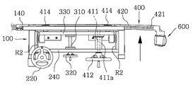
상기 만곡레일부(400)는 상기 전후이동부(300)의 일측에 설치되어 레일이송수단(410)에 의해 좌측 또는 우측으로 이송되며, 만곡된 형상의 호형으로 형성되어 길이방향으로 결합되는 다수개의 단위레일(420)과, 상기 다수개의 단위레일(420)의 길이방향을 따라 설치된 동력전달축(430)으로 구성된 것으로, 바람직한 구성으로는 다음과 같다.The
상기 단위레일(420)에는 길이방향을 따라 톱니(421)가 형성되며,In the
상기 레일이송수단(410)은 상기 전후이동몸체(330)를 관통하는 레일이송축(411)과, 상기 레일이송축(411)의 전단부에 형성된 레일이송핸들(412)과, 상기 레일이송축(411)의 후단부에 형성되어 상기 톱니(421)와 이물림 되는 레일이송기어(413)와, 상기 전후이동몸체(330)의 상·하부에 설치되어 상기 단위레일(420)을 지지하는 레일롤러(414)로 구성하는 것이 바람직하며, 상기와 같이 형성된 레일이송핸들(412)을 회전시키게 되면 상기 레일이송기어(413)과 상기 톱니(421)가 이물림되어 있으므로 그 레일이송핸들(412)의 회전방향에 따라 상기 길이방향으로 결합된 다수개의 단위레일(420)이 좌측 또는 우측으로 이송되는 것이다.The
이때, 상기 레일롤러(414)에는 상기 단위레일(420)을 지지하되 상기 톱니(421)가 파손되지 않고 지날 수 있도록 도면에 도시된 바와 같이 홈을 형성하는 것이 바람직하다.At this time, it is preferable that the
또한, 상기 레일이송축(411)의 보호를 위해 도면에 도시된 바와 같이 그 레일이송축(411)을 감싸는 보호커버(411a)를 설치할 수 있으며, 이때 상기 보호커버(411a)는 후단이 상기 전후이동몸체(330)에 고정되고 전단부는 상기 상하이동몸체(240)를 관통하여 전방 또는 후방으로 유동할 수 있도록 설치되는 것이 바람직하다.As shown in the figure, the rails may be provided with a
상기와 같이 구성된 상기 만곡레일부(400)를 이루는 각각의 단위레일(420)이 만곡되게 형성되는 이유는 격납건물(1) 외벽의 형태가 환형으로 형성되어 있고 그 외벽의 내측면에 설치되어 있는 라이너플레이트(10)와 그 라이너플레이트(10)와 마주하는 내부구조물(20) 간의 사이 공간 역시 상기 격납건물(1) 외벽의 형태를 따라 호형으로 형성되어 있으므로, 일반적인 직선형의 도구로는 라이너플레이트(10)와 내부구조물 간(20)의 사이 공간에 삽입하여 임시부착물(11)에 접근할 수 없기 때문이다.The reason why each
또한, 상기 만곡레일부(400)를 이루는 단위레일(420)의 수는 도면에 도시된 개수에 한정되지 아니하며, 작업현장에 따라 추가 연결하여 형성시킬 수 있다.In addition, the number of the
상기 절삭툴(500)은 상기 만곡레일부(400)의 일측 끝단에 설치되며 원자로 격납건물(1)의 라이너플레이트(10)에 부착된 임시부착물(11)을 제거하기 위해 설치되는 절삭날(510)을 포함하여 형성된 것이며, 상기 절삭날(510)은 상기 동력전달축(430)과 연결된 것으로, 그 형태는 상기 절삭날(510)을 구동시킬 수 있는 어떠한 형태의 공구를 사용해도 무방하다.The
또한, 상기 임시부착물(11) 이외에도 상기 내부구조물(20)은 콘크리트로 형성되어 있어, 그 면이 고르지 않고 울툴불퉁한 돌출면이 있어 상기 임시부착물(11)을 제거하는데 어려움이 수반될 수 있으므로, 도 7에 도시된 바와 같이 상기 절삭툴(500)에 설치된 절삭날(510)은 라이너플레이트(10)에 부착된 임시부착물(11)과 내부구조물(20)의 면을 동시에 연마할 수 있도록 전방과 후방에 각각 설치할 수도 있다.In addition to the
이때, 상기 동력전달축(430)과 상기 절삭날(510)은 회전하는 축방향이 동일하지 않고 교차되어 있으므로 그 연결을 베벨기어방식으로 연결하는 것이 바람직하다.At this time, since the
상기 구동모터부(600)는 상기 만곡레일부(400)의 타측 끝단에 설치되며 상기 동력전달축(430)과 연결되어 상기 동력전달축(430)과 연결된 절삭날(510)을 회전시키기 위해 형성된 것으로, 어떠한 모터를 사용해도 무방하며 상기 동력전달축(430)과의 연결은 설치 방법에 따라 동일한 축방향으로 연결하거나, 축의 방향이 동일하지 않은 경우에는 베벨기어방식으로 연결해도 무방하다.The
또한, 상기 하부프레임(110)의 하단부에는 프레임부(100)가 임의로 유동하지 않고 지면에 매설된 라이너플레이트(10)와 자성에 의해 고정될 수 있도록 마그네틱부(700)가 하나 이상 설치되어 안정적인 임시부착물 제거작업을 유도할 수 있는 효과가 있다.In addition, at least one of the
또한, 상기 수직프레임(120)의 좌·우 양측 또는 좌측과 우측 어느 하나에 라이너플레이트(10)와 내부구조물(20) 사이 공간에 삽입되어 상기 프레임부(100)가 유동하지 않도록 하는 프레임고정구(140)를 설치할 수 있으며 이때, 상기 프레임고정구(140)는 도면에 도시된 바와 같이 상기 수직프레임(120)의 상부와 하부에 각각 설치되는 것이 프레임부(100)를 고정하는데 바람직하며, 상기 프레임고정구(140)는 볼트방식으로 형성되어 일측 방향으로 회전하면 전방으로 돌출되어 상기 라이너플레이트(10)와 내부구조물(20) 사이 공간에 밀착 고정되며 상기 프레임(100)부가 임의로 유동하지 않을 수 있게 된다.The frame fixture (100) is inserted into a space between the liner plate (10) and the inner structure (20) on either the left or right side or the left and right sides of the vertical frame (120) The
상기와 같이 프레임부(100)가 고정됨으로써 작업시에 장치의 진동을 줄여 보다 정밀하게 임시부착물 제거 작업을 유도할 수 있게 되는 효과가 있다.By fixing the
상기와 같이 이루어진 원자로 격납건물의 임시부착물 제거장치에 따르면, 라이너플레이트와 내부구조물 간의 협소한 사이 공간에 삽입되어 그 라이너플레이트에 부착된 임시부착물을 절삭 또는 연마할 수 있는 효과가 있으며, 또한, 상기 라이너플레이트와 마주하는 내부구조물에 형성된 콘크리트 간섭부 역시 연마하여 제거할 수 있는 효과가 있다.According to the temporary deposit removing apparatus of the above-described reactor containment structure, it is possible to cut or polish a temporary deposit attached to a narrow space between the liner plate and the inner structure and attached to the liner plate, The concrete interfering portion formed in the inner structure facing the liner plate can also be polished and removed.
이상, 첨부된 도면을 참조하여 본 발명의 바람직한 일 실시 예를 설명하였지만, 본 발명이 속하는 기술분야에서 통상의 지식을 가진 자라면 본 발명이 그 기술적 사상이나 필수적인 특징을 변경하지 않고서 다른 구체적인 형태로 실시될 수 있다는 것을 이해할 수 있을 것이다.While the present invention has been described in connection with what is presently considered to be practical exemplary embodiments, it is to be understood that the invention is not limited to the disclosed embodiments, but, on the contrary, It will be understood that the invention may be practiced.
그러므로 이상에서 기술한 일 실시 예는 모든 면에서 예시적인 것이며 한정적이 아닌 것으로 이해해야만 한다.It is therefore to be understood that one embodiment described above is illustrative in all aspects and not restrictive.
1 : 원자로 격납건물 10 : 라이너플레이트
11 : 임시부착물 20 : 내부구조물
100 : 프레임부 110 : 하부프레임
120 : 수직프레임 130 : 상부프레임
200 : 상하이동부 210 : 상하이동축
220 : 상하이동부핸들 230 : 상하이동브라켓
240 : 상하이동몸체 300 : 전후이동부
310 : 전후이동축 320 : 전후이동부핸들
330 : 전후이동몸체 400 : 만곡레일부
410 : 레일이송수단 420 : 단위레일
430 : 동력전달축 500 : 절삭툴
510 : 절삭날 600 : 구동모터부
700 : 마그네틱부1: reactor containment building 10: liner plate
11: temporary attachment 20: internal structure
100: frame part 110: lower frame
120: vertical frame 130: upper frame
200: Shanghai East 210: Shanghai Coaxial
220: Shanghai east handle 230: Up and down moving bracket
240: Up and down moving body 300:
310: front and rear coaxial 320: front and rear east handle
330: front and rear moving body 400:
410: rail conveying means 420: unit rail
430: Power transmission shaft 500: Cutting tool
510: cutting edge 600: drive motor section
700: Magnetic part
Claims (7)
상기 수직프레임(120)의 길이방향을 따라 상방 또는 하방으로 이동되게 설치된 상하이동부(200);
상기 상하이동부(200)의 일측에 설치되어 전방 또는 후방으로 이동되는 전후이동부(300);
상기 전후이동부(300)의 일측에 설치되어 레일이송수단(410)에 의해 좌측 또는 우측으로 이송되며, 만곡된 형상의 호형으로 형성되어 길이방향으로 결합되는 다수개의 단위레일(420)과, 상기 다수개의 단위레일(420)의 길이방향을 따라 설치된 동력전달축(430)으로 구성된 만곡레일부(400);
상기 만곡레일부(400)의 일측 끝단에 원자로 격납건물의 라이너플레이트에 부착된 임시부착물을 제거하기 위해 설치되는 절삭날(510)을 갖으며 상기 절삭날(510)은 상기 동력전달축(430)과 연결된 절삭툴(500);
상기 만곡레일부(400)의 타측 끝단에 설치되며 상기 동력전달축(430)과 연결되어 상기 동력전달축(430)과 연결된 절삭날(510)을 회전시키는 구동모터부(600);로 이루어지며,
상기 수직프레임(120)의 후면에는 길이방향을 따라 수직레일(R1)이 형성되고, 상기 수직프레임(120)의 좌·우 양측에는 전·후방 길이방향을 따라 전후방레일(R2)이 형성되며,
상기 상하이동부(200)는, 상기 수직프레임(120)의 일측에 수직으로 설치되며 외주면에 나사산이 형성된 상하이동축(210)과, 상기 상하이동축(210)의 상단에 형성된 상하이동부핸들(220)과, 상기 상하이동축(210)에 나사결합된 상하이동브라켓(230)과, 상기 상하이동브라켓(230)과 일체로 형성되며 좌·우 양측이 상기 수직레일(R1)에 끼움설치되어 상기 상하이동부핸들(220)의 회전방향에 따라 상기 상하이동브라켓(230)과 함께 상방 또는 하방으로 이동하는 상하이동몸체(240)으로 구성된 것을 특징으로 하는 원자로 격납건물의 임시부착물 제거장치.A vertical frame 120 vertically formed at a predetermined height on both left and right sides of the lower frame 110 and an upper frame 130 formed at an upper end of the vertical frame 120. [ (100);
A vertical moving part 200 installed to be moved upward or downward along the longitudinal direction of the vertical frame 120;
A forward / backward moving part 300 installed on one side of the up / down moving part 200 and moving forward or backward;
A plurality of unit rails 420 installed at one side of the front and rear moving unit 300 and being conveyed to the left or right by the rail conveying means 410 and formed in a curved arc shape and coupled in the longitudinal direction, A curved rail part 400 constituted by a power transmission shaft 430 installed along the longitudinal direction of the unit rail 420;
The cutting edge 510 is provided at one end of the curved rail part 400 to remove a temporary attachment attached to the liner plate of the nuclear reactor containment building. A cutting tool 500 connected to the cutting tool 500;
And a driving motor part 600 installed at the other end of the curved rail part 400 and connected to the power transmission shaft 430 to rotate the cutting blade 510 connected to the power transmission shaft 430 ,
A vertical rail R1 is formed on the rear surface of the vertical frame 120 along the longitudinal direction and front and rear rails R2 are formed on both left and right sides of the vertical frame 120 along the longitudinal direction.
The upper and lower moving parts 200 are vertically installed on one side of the vertical frame 120 and have upper and lower coaxial axes 210 formed with threads on the outer circumferential surface and upper and lower moving parts 220 formed on the upper ends of the upper and lower coaxial axes 210, A vertical moving bracket 230 screwed to the upper coaxial shaft 210 and a vertical moving bracket 230 integrally formed with the vertical moving bracket 230 and having both left and right sides fitted into the vertical rail R1, And a vertical moving body (240) moving upward or downward together with the up and down moving brackets (230) according to the rotation direction of the movable body (220).
상기 전후이동부(300)는, 상기 상하이동몸체(240)의 중앙부를 후방으로 관통하여 설치되고 외주면에 나사산이 형성된 전후이동축(310)과, 상기 전후이동축(310)의 전단부에 형성된 전후이동부핸들(320)과, 상기 전후이동축(310)의 후단부가 중앙부에 회동되게 설치되며 상기 전후방레일(R2)에 좌·우 양측이 끼움설치되어 상기 전후이동부핸들(320)의 회전방향에 따라 전방 또는 후방으로 이동하는 전후이동몸체(330)으로 구성된 것을 특징으로 하는 원자로 격납건물의 임시부착물 제거장치.The method according to claim 1,
The front and rear moving part 300 includes a forward and backward coaxial shaft 310 which is formed to penetrate rearward through a central part of the up and down moving body 240 and has threads formed on an outer circumferential surface thereof, And a rear end of the front and rear coaxial shafts 310 is rotatably installed at a central portion of the front and rear coaxial shafts 310. The front and rear coaxial shafts 310 are rotatably mounted on the front and rear rails R2, And a front and rear moving bodies (330) that move to the front and rear sides of the reactor.
상기 단위레일(420)에는 길이방향을 따라 톱니(421)가 형성되며,
상기 레일이송수단(410)은 상기 전후이동몸체(330)를 관통하는 레일이송축(411)과, 상기 레일이송축(411)의 전단부에 형성된 레일이송핸들(412)과, 상기 레일이송축(411)의 후단부에 형성되어 상기 톱니(421)와 이물림 되는 레일이송기어(413)와, 상기 전후이동몸체(330)의 상·하부에 설치되어 상기 단위레일(420)을 지지하는 레일롤러(414)로 구성된 것을 특징으로 하는 원자로 격납건물의 부착물 제거장치.The method of claim 3,
In the unit rail 420, teeth 421 are formed along the longitudinal direction,
The rail conveying means 410 includes a rail 411 passing through the front and rear moving bodies 330 and a rail conveying handle 412 formed at a front end of the rail 411, A rail feed gear 413 formed at the rear end of the unit rail 411 to be engaged with the teeth 421 and a rail 423 which is installed on upper and lower portions of the front and rear moving bodies 330, And a roller (414).
상기 절삭툴(500)에 설치된 절삭날(510)은 라이너플레이트(10)에 부착된 임시부착물(11)과 내부구조물(20)의 면을 동시에 연마할 수 있도록 전방과 후방에 각각 설치된 것을 특징으로 하는 원자로 격납건물의 임시부착물 제거장치.The method according to claim 1,
The cutting edge 510 provided on the cutting tool 500 is installed at the front and rear so as to simultaneously polish the surfaces of the temporary attachment 11 and the inner structure 20 attached to the liner plate 10 A device for removing temporary deposits in a reactor containment building.
상기 하부프레임(110)의 하단부에는 프레임부(100)가 임의로 유동하지 않고 지면에 매설된 라이너플레이트(10)와 자성에 의해 고정될 수 있도록 마그네틱부(700)가 하나 이상 설치된 것을 특징으로 하는 원자로 격납건물의 임시부착물 제거장치.The method according to claim 1,
Wherein at least one of the liner plate (10) embedded in the ground and the magnetic part (700) is fixed to the bottom part of the lower frame (110) so that the frame part (100) A temporary attachment removal device in a containment building.
상기 수직프레임(120)의 좌·우 양측 또는 좌측과 우측 어느 하나에 라이너플레이트(10)와 내부구조물(20) 사이 공간에 삽입되어 상기 프레임부(100)가 유동하지 않도록 하는 프레임고정구(140)가 설치된 것을 특징으로 하는 원자로 격납건물의 임시부착물 제거장치.The method according to claim 1,
A frame fixture 140 inserted into a space between the liner plate 10 and the inner structure 20 on either the left or right side or the left and right sides of the vertical frame 120 to prevent the frame 100 from flowing, Wherein the apparatus is installed in a nuclear reactor.
Priority Applications (1)
| Application Number | Priority Date | Filing Date | Title |
|---|---|---|---|
| KR1020170089562A KR101839552B1 (en) | 2017-07-14 | 2017-07-14 | Apparatus for temporary attachment removal of nuclear power plants |
Applications Claiming Priority (1)
| Application Number | Priority Date | Filing Date | Title |
|---|---|---|---|
| KR1020170089562A KR101839552B1 (en) | 2017-07-14 | 2017-07-14 | Apparatus for temporary attachment removal of nuclear power plants |
Publications (1)
| Publication Number | Publication Date |
|---|---|
| KR101839552B1 true KR101839552B1 (en) | 2018-04-27 |
Family
ID=62081353
Family Applications (1)
| Application Number | Title | Priority Date | Filing Date |
|---|---|---|---|
| KR1020170089562A Active KR101839552B1 (en) | 2017-07-14 | 2017-07-14 | Apparatus for temporary attachment removal of nuclear power plants |
Country Status (1)
| Country | Link |
|---|---|
| KR (1) | KR101839552B1 (en) |
Cited By (1)
| Publication number | Priority date | Publication date | Assignee | Title |
|---|---|---|---|---|
| KR102710434B1 (en) * | 2024-08-09 | 2024-09-26 | 주식회사 에스이 | End cutting device for H-beam structure in CLP |
Citations (2)
| Publication number | Priority date | Publication date | Assignee | Title |
|---|---|---|---|---|
| JP2001071201A (en) | 1999-09-06 | 2001-03-21 | Toshiba Corp | Processing equipment for cylindrical parts |
| JP2003021698A (en) | 2001-07-10 | 2003-01-24 | Atox Co Ltd | Cutting decontamination method, and cutting decontamination device for contaminated metal surface |
-
2017
- 2017-07-14 KR KR1020170089562A patent/KR101839552B1/en active Active
Patent Citations (2)
| Publication number | Priority date | Publication date | Assignee | Title |
|---|---|---|---|---|
| JP2001071201A (en) | 1999-09-06 | 2001-03-21 | Toshiba Corp | Processing equipment for cylindrical parts |
| JP2003021698A (en) | 2001-07-10 | 2003-01-24 | Atox Co Ltd | Cutting decontamination method, and cutting decontamination device for contaminated metal surface |
Cited By (1)
| Publication number | Priority date | Publication date | Assignee | Title |
|---|---|---|---|---|
| KR102710434B1 (en) * | 2024-08-09 | 2024-09-26 | 주식회사 에스이 | End cutting device for H-beam structure in CLP |
Similar Documents
| Publication | Publication Date | Title |
|---|---|---|
| KR101584679B1 (en) | Apparatus for circular cutting road surface with manhole housing clamper | |
| KR101610483B1 (en) | Treatment device and method for waste steam generator, and installation method of treatment device for waste steam generator | |
| EP4265347A1 (en) | Diamond wire saw dry-cutting method | |
| KR101839552B1 (en) | Apparatus for temporary attachment removal of nuclear power plants | |
| US10217535B2 (en) | Device and method for removing contaminated material | |
| US20200002964A1 (en) | System and method for hydro-demolition of concrete structures | |
| KR101146181B1 (en) | Manhole frame repair device and manhole repairing method using the same | |
| KR20160046396A (en) | Apparatus for circular drilling and cutting road surface to repair a manhole | |
| JP6715667B2 (en) | Reconstruction method for lining of existing 2-lane road tunnel | |
| GB2301221A (en) | Surface decontamination | |
| KR102650602B1 (en) | Automatic plate cutting smart factory system | |
| KR100711708B1 (en) | Concrete file cutting device for foundation workers | |
| KR101600415B1 (en) | Beveller for welding beveling and improved welding method using the same | |
| CN113314246A (en) | Device and method for decommissioning radioactive chimney | |
| KR101886574B1 (en) | Repair system of containment wall | |
| KR200467068Y1 (en) | Apparatus for welding automatically | |
| CN205802213U (en) | A kind of lightning rod production blanking device | |
| CN104842440A (en) | U-shaped frame dustproof cutting vehicle for producing autoclaved aerated blocks | |
| CN202450424U (en) | Inspection well milling device locating device | |
| KR101645704B1 (en) | Automatic chamfering machine | |
| KR101572019B1 (en) | Apparatus and method for crushing concrete structure repairing the bottom | |
| KR101931640B1 (en) | Milling apparatus and method for circular structure | |
| KR100597069B1 (en) | Concrete Pile Automatic Cutting Device | |
| CN213379021U (en) | Concrete sleeper reinforcement cutting machine | |
| CN210316650U (en) | Building construction safety device |
Legal Events
| Date | Code | Title | Description |
|---|---|---|---|
| PA0109 | Patent application |
St.27 status event code: A-0-1-A10-A12-nap-PA0109 |
|
| PA0201 | Request for examination |
St.27 status event code: A-1-2-D10-D11-exm-PA0201 |
|
| PA0302 | Request for accelerated examination |
St.27 status event code: A-1-2-D10-D17-exm-PA0302 St.27 status event code: A-1-2-D10-D16-exm-PA0302 |
|
| D13-X000 | Search requested |
St.27 status event code: A-1-2-D10-D13-srh-X000 |
|
| D14-X000 | Search report completed |
St.27 status event code: A-1-2-D10-D14-srh-X000 |
|
| PE0902 | Notice of grounds for rejection |
St.27 status event code: A-1-2-D10-D21-exm-PE0902 |
|
| E13-X000 | Pre-grant limitation requested |
St.27 status event code: A-2-3-E10-E13-lim-X000 |
|
| P11-X000 | Amendment of application requested |
St.27 status event code: A-2-2-P10-P11-nap-X000 |
|
| P13-X000 | Application amended |
St.27 status event code: A-2-2-P10-P13-nap-X000 |
|
| P11-X000 | Amendment of application requested |
St.27 status event code: A-2-2-P10-P11-nap-X000 |
|
| P13-X000 | Application amended |
St.27 status event code: A-2-2-P10-P13-nap-X000 |
|
| R15-X000 | Change to inventor requested |
St.27 status event code: A-3-3-R10-R15-oth-X000 |
|
| R16-X000 | Change to inventor recorded |
St.27 status event code: A-3-3-R10-R16-oth-X000 |
|
| PN2301 | Change of applicant |
St.27 status event code: A-3-3-R10-R13-asn-PN2301 St.27 status event code: A-3-3-R10-R11-asn-PN2301 |
|
| PE0701 | Decision of registration |
St.27 status event code: A-1-2-D10-D22-exm-PE0701 |
|
| GRNT | Written decision to grant | ||
| PR0701 | Registration of establishment |
St.27 status event code: A-2-4-F10-F11-exm-PR0701 |
|
| PR1002 | Payment of registration fee |
St.27 status event code: A-2-2-U10-U11-oth-PR1002 Fee payment year number: 1 |
|
| PG1601 | Publication of registration |
St.27 status event code: A-4-4-Q10-Q13-nap-PG1601 |
|
| PN2301 | Change of applicant |
St.27 status event code: A-5-5-R10-R11-asn-PN2301 |
|
| PN2301 | Change of applicant |
St.27 status event code: A-5-5-R10-R14-asn-PN2301 |
|
| P14-X000 | Amendment of ip right document requested |
St.27 status event code: A-5-5-P10-P14-nap-X000 |
|
| PR1001 | Payment of annual fee |
St.27 status event code: A-4-4-U10-U11-oth-PR1001 Fee payment year number: 4 |
|
| R18-X000 | Changes to party contact information recorded |
St.27 status event code: A-5-5-R10-R18-oth-X000 |
|
| PR1001 | Payment of annual fee |
St.27 status event code: A-4-4-U10-U11-oth-PR1001 Fee payment year number: 5 |
|
| PR1001 | Payment of annual fee |
St.27 status event code: A-4-4-U10-U11-oth-PR1001 Fee payment year number: 6 |
|
| PR1001 | Payment of annual fee |
St.27 status event code: A-4-4-U10-U11-oth-PR1001 Fee payment year number: 7 |
|
| PR1001 | Payment of annual fee |
St.27 status event code: A-4-4-U10-U11-oth-PR1001 Fee payment year number: 8 |
|
| U11 | Full renewal or maintenance fee paid |
Free format text: ST27 STATUS EVENT CODE: A-4-4-U10-U11-OTH-PR1001 (AS PROVIDED BY THE NATIONAL OFFICE) Year of fee payment: 8 |