KR101796271B1 - Apparatus And Method For Reporting Radio Link Failure - Google Patents
Apparatus And Method For Reporting Radio Link Failure Download PDFInfo
- Publication number
- KR101796271B1 KR101796271B1 KR1020110039647A KR20110039647A KR101796271B1 KR 101796271 B1 KR101796271 B1 KR 101796271B1 KR 1020110039647 A KR1020110039647 A KR 1020110039647A KR 20110039647 A KR20110039647 A KR 20110039647A KR 101796271 B1 KR101796271 B1 KR 101796271B1
- Authority
- KR
- South Korea
- Prior art keywords
- radio link
- link failure
- rlf
- information
- communication system
- Prior art date
Links
Images


Classifications
-
- H—ELECTRICITY
- H04—ELECTRIC COMMUNICATION TECHNIQUE
- H04B—TRANSMISSION
- H04B1/00—Details of transmission systems, not covered by a single one of groups H04B3/00 - H04B13/00; Details of transmission systems not characterised by the medium used for transmission
- H04B1/06—Receivers
- H04B1/10—Means associated with receiver for limiting or suppressing noise or interference
- H04B1/1027—Means associated with receiver for limiting or suppressing noise or interference assessing signal quality or detecting noise/interference for the received signal
-
- H—ELECTRICITY
- H04—ELECTRIC COMMUNICATION TECHNIQUE
- H04B—TRANSMISSION
- H04B15/00—Suppression or limitation of noise or interference
- H04B15/02—Reducing interference from electric apparatus by means located at or near the interfering apparatus
-
- H—ELECTRICITY
- H04—ELECTRIC COMMUNICATION TECHNIQUE
- H04B—TRANSMISSION
- H04B17/00—Monitoring; Testing
- H04B17/20—Monitoring; Testing of receivers
- H04B17/24—Monitoring; Testing of receivers with feedback of measurements to the transmitter
-
- H—ELECTRICITY
- H04—ELECTRIC COMMUNICATION TECHNIQUE
- H04B—TRANSMISSION
- H04B17/00—Monitoring; Testing
- H04B17/30—Monitoring; Testing of propagation channels
- H04B17/309—Measuring or estimating channel quality parameters
- H04B17/345—Interference values
-
- H—ELECTRICITY
- H04—ELECTRIC COMMUNICATION TECHNIQUE
- H04W—WIRELESS COMMUNICATION NETWORKS
- H04W24/00—Supervisory, monitoring or testing arrangements
- H04W24/10—Scheduling measurement reports ; Arrangements for measurement reports
-
- H—ELECTRICITY
- H04—ELECTRIC COMMUNICATION TECHNIQUE
- H04W—WIRELESS COMMUNICATION NETWORKS
- H04W76/00—Connection management
- H04W76/10—Connection setup
- H04W76/19—Connection re-establishment
-
- H—ELECTRICITY
- H04—ELECTRIC COMMUNICATION TECHNIQUE
- H04W—WIRELESS COMMUNICATION NETWORKS
- H04W88/00—Devices specially adapted for wireless communication networks, e.g. terminals, base stations or access point devices
- H04W88/02—Terminal devices
- H04W88/06—Terminal devices adapted for operation in multiple networks or having at least two operational modes, e.g. multi-mode terminals
Abstract
본 명세서는, 무선 링크 실패 보고 장치 및 방법에 관한 것으로, 무선 링크 실패(Radio Link Failure: RLF)가 발생하는 원인에 따른 단말 또는 기지국의 동작과 네트워크의 운영 방안들을 개시한다. 보다 구체적으로 무선 링크 실패가 발생하는 원인 중 장치 내 다른 송수신 장치의 수신 전력 및/또는 간섭 전력을 보고함으로써 네트워크 운용의 효율을 높일 수 있도록 한다. 본 명세서는 무선 링크 실패를 감지하여, 무선 링크 실패에 관한 무선 링크 실패 보고를 구성하고무선 링크 실패 보고를 전송하는 구성들을 포함한다. 여기서, 무선 링크 실패 보고는 무선 링크 실패에 대하여 기기 내 공존 간섭에 의한 영향이 있었는지에 관한 정보를 포함한다. The present disclosure relates to a radio link failure reporting apparatus and method, and discloses an operation of a terminal or a base station and an operation method of a network according to a cause of a radio link failure (RLF). More specifically, it is possible to increase the efficiency of network operation by reporting received power and / or interference power of other transceivers in the apparatus among the causes of radio link failure. The present disclosure includes configurations for detecting a radio link failure, configuring a radio link failure report for a radio link failure, and sending a radio link failure report. Here, the radio link failure report includes information as to whether there has been an influence due to intra-device coexistence interference with the radio link failure.

Description
본 발명은 무선통신에 관한 것으로서, 구체적으로는 무선 링크 실패(Radio Link Failure: RLF, 이하 'RLF'라 함)를 보고하는 장치 및 방법에 관한 것이다. BACKGROUND OF THE
무선통신 시스템은 일반적으로 데이터 송신을 위해 하나의 대역폭을 이용한다. 예를 들어, 2세대 무선통신 시스템은 200KHz ~ 1.25MHz의 대역폭을 사용하고, 3세대 무선통신 시스템은 5MHz ~ 10 MHz의 대역폭을 사용한다. 증가하는 송신 용량을 지원하기 위해, 최근의 3GPP(3rd Generation Partnership Project) LTE(Long Term Evolution) 또는 IEEE 802.16m은 20MHz 또는 그 이상까지 계속 그 대역폭을 확장하고 있다. Wireless communication systems typically use one bandwidth for data transmission. For example, a second-generation wireless communication system uses a bandwidth of 200 KHz to 1.25 MHz, and a third-generation wireless communication system uses a bandwidth of 5 MHz to 10 MHz. To support increasing transmission capacity, the latest 3GPP (Long Term Evolution) or IEEE 802.16m (3GPP) continues to extend its bandwidth to 20 MHz or more.
한편, 하나의 단말이 하나의 네트워크 시스템과 통신을 수행하던 종래에는 사용자는 각 네트워크 시스템을 지원하는 서로 다른 기기를 휴대하였다. 그러나, 최근에는 유비퀴터스(ubiquitous) 접속 네트워크로 인해, 사용자들은 서로 다른 지역에서 동일한 네트워크에 접속할 수 있을 뿐 아니라, 동일한 장소에서 서로 다른 네트워크에 접속할 수도 있다. 이를 지원하기 위해, 단말의 기능이 고도화되고 복잡해졌고, 하나의 단말로도 다수의 네트워크 시스템에 접속하여 통신을 수행할 수 있게 되었다. 따라서, 사용자 편의가 증대되고, 대역폭 또한 효과적으로 활용하는 효과를 얻게 되었다. Meanwhile, in a conventional manner in which one terminal performs communication with one network system, the user carries different devices supporting each network system. However, in recent years, due to the ubiquitous access network, users can not only access the same network in different areas but also connect to different networks in the same place. In order to support this, the functions of the terminal have become sophisticated and complex, and one terminal can connect to a plurality of network systems to perform communication. Therefore, the user convenience is increased and the bandwidth is effectively utilized.
그러나, 서로 다른 통신 시스템의 송수신 장치에 의한 간섭 발생로 인하여, 무선통신시스템의 성능 저하가 발생하는 문제점을 존재하게 된다. 따라서, 이러한 무선통신 시스템의 성능 저하를 해결하기 위한 요구가 필요한 실정이다. However, there is a problem that the performance of the wireless communication system deteriorates due to the interference caused by the transmitting and receiving apparatuses of different communication systems. Therefore, there is a need for a solution to the deterioration of the performance of such a wireless communication system.
본 발명은 무선 통신 시스템에서 무선 링크 실패(이하 'RLF'라 칭함)가 발생하는 원인에 대한 정보를 보고할 수 있는 장치 및 방법을 제공하고자 한다.The present invention provides an apparatus and method for reporting information on a cause of radio link failure (hereinafter referred to as 'RLF') in a wireless communication system.
본 발명은 무선 통신 시스템에서 RLF 정보를 획득하여 네트워크 품질을 개선하는 장치 및 방법을 제공하고자 한다.The present invention intends to provide an apparatus and method for acquiring RLF information in a wireless communication system to improve network quality.
본 발명은 무선 통신 시스템에서 RLF 원인에 따른 RLF 보고 구성 장치 및 방법을 제공하고자 한다. An apparatus and method for configuring an RLF report according to the cause of an RLF in a wireless communication system.
본 발명은 무선 통신 시스템에서 UE 내 서로 다른 통신 장치에 의한 간섭으로 발생하는 RLF 정보를 보고하는 장치 및 방법을 제공하고자 한다. An apparatus and method for reporting RLF information caused by interference by different communication apparatuses in a UE in a wireless communication system.
본 발명은 무선통신시스템에서 UE 내 서로 다른 통신 시스템의 송수신 장치에 의한 신호의 수신 전력 및/또는 간섭 전력을 측정한 값을 RLF 정보에 포함하여 보고하는 장치 및 방법을 제공하고자 한다.The present invention provides an apparatus and a method for reporting received power and / or interference power of a signal by a transmitting / receiving apparatus of different communication systems in a UE in a wireless communication system by including the measured value in RLF information.
본 발명의 일 실시형태는 단말의 무선 링크 실패 보고 방법으로서, 무선 링크 실패를 감지하는 단계, 무선 링크 실패에 관한 무선 링크 실패 보고를 구성하는 단계 및 무선 링크 실패 보고를 전송하는 단계를 포함하며, 무선 링크 실패 보고는 상기 무선 링크 실패에 대하여 기기 내 공존 간섭에 의한 영향이 있었는지에 관한 정보를 포함한다. An embodiment of the present invention is a method of reporting a radio link failure of a terminal, comprising: detecting a radio link failure; configuring a radio link failure report on a radio link failure; and transmitting a radio link failure report, The radio link failure report includes information as to whether there has been an effect due to intra-device coexistence interference with the radio link failure.
이때, 무선 링크 실패 보고는 기기 내 공존 간섭을 발생시킨 통신 시스템을 지시하는 정보를 포함할 수 있다. At this time, the radio link failure report may include information indicating a communication system in which coexistence interference has occurred in the device.
또한, 무선 링크 실패 보고는 무선 링크 실패가 발생한 단말 내 제1 통신 시스템에 대한 단말 내 제2 통신 시스템 신호의 수신 전력 및/또는 간섭 전력을 측정한 값을 지시하는 정보를 포함할 수 있다. In addition, the radio link failure report may include information indicating a value obtained by measuring a received power and / or an interference power of a second communication system signal in a terminal for a first communication system in a terminal where a radio link failure occurs.
여기서, 제1 통신 시스템에 대한 제2 통신 시스템 신호의 수신 전력은, 제1 통신 시스템이 이용하는 대역 내에서 제1 통신 시스템의 측정 방식에 의해 측정된 제2 통신 시스템 신호의 수신 전력을 나타내며, 제1 통신 시스템에 대한 제2 통신 시스템 신호의 간섭 전력은, 제1 통신 시스템이 이용하는 대역 내에서 수신된 모든 신호의 수신 전력에 대한 제2 통신 시스템 신호의 수신 전력을 제1 통신 시스템의 측정 방식에 의해 측정한 값을 나타낸다.Here, the reception power of the second communication system signal for the first communication system represents the reception power of the second communication system signal measured by the measurement system of the first communication system within the band used by the first communication system, The interference power of the second communication system signal for the first communication system is determined by the received power of the second communication system signal with respect to the received power of all signals received within the band used by the first communication system, .
한편, 무선 링크 실패 보고는 해당 무선 링크 실패 이후 실행되는 RRC 연결 재설정 절차에서 RRC 연결 재설정 요구 메시지에 포함되어 전송될 수 있으며, E-UTRAN으로부터의 단말 정보 제공 요구에 대한 응답으로서 전송될 수도 있다.Meanwhile, the radio link failure report may be included in the RRC connection re-establishment request message in the RRC connection re-establishment procedure executed after the radio link failure, and may be transmitted as a response to the terminal information provision request from the E-UTRAN.
본 발명의 다른 실시형태는 기지국의 무선 링크 실패 보고 처리 방법으로서, 무선 링크 실패 보고를 수신하는 단계 및 무선 링크 실패가 발생한 셀에 무선 링크 실패에 관한 정보를 전송하는 단계를 포함하며, 무선 링크 실패가 발생한 셀은 무선 링크 실패 보고를 기반으로 판단된다.Another embodiment of the present invention is a method of processing a radio link failure report of a base station, the method comprising: receiving a radio link failure report; and transmitting information about a radio link failure to a cell where the radio link failure occurred, Is determined based on the radio link failure report.
무선 링크 실패 보고가 무선 링크 실패에 관한 단말의 기기 내 공존 간섭 정보를 포함하는 경우에는, 무선 링크 실패가 발생한 셀이 기기 내 공존 간섭에 관한 정보를 필요로 하는 경우에만 단말의 기기 내 공존 간섭 정보를 전송할 수도 있다.In the case where the radio link failure report includes the intra-device coexistence interference information of the terminal related to the radio link failure, only when the cell in which the radio link failure occurs requires the information on intra-device coexistence interference, Lt; / RTI >
무선 링크 실패 보고는 상기 무선 링크 실패가 발생한 단말로부터의 RRC 연결 재설정 요구 메시지에 포함되어 전송된 것일 수도 있고, E-UTRAN의 단말 정보 제공 요구에 대한 응답으로서 전송된 것일 수도 있다. 한편, 무선 링크 실패에 관한 정보는 X2 인터페이스를 통해 전송될 수 있다.The radio link failure report may be included in the RRC connection re-establishment request message from the terminal in which the radio link failure has occurred, or may have been transmitted as a response to the E-UTRAN terminal information provision request. On the other hand, information on the radio link failure can be transmitted via the X2 interface.
본 발명에 의하면, RLF가 발생하는 원인에 따라 RLF 정보를 정확하게 보고할 수 있으며, 이를 네트워크에서 공유함으로써, 네트워크 품질을 효과적으로 개선할 수 있다.According to the present invention, the RLF information can be accurately reported according to the cause of occurrence of the RLF, and the network quality can be effectively improved by sharing the RLF information with the network.
본 발명에 의하면, UE 내 서로 다른 통신 시스템의 송수신 장치에 의한 간섭을 통해서 발생한 RLF에 관해서도 보고할 수 있으며, 이 때, 서로 다른 시스템의 송수신 장치에 의해 간섭이 발생했다는 정보 외에, 각 시스템의 송수신 장치에 의한 신호의 수신 전력 및/또는 간섭 전력을 측정한 값을 RLF 정보에 포함하여 더 정확한 RLF 보고가 이루어지도록 할 수 있다.According to the present invention, it is possible to report RLFs generated through interference by transceivers of different communication systems in a UE. At this time, in addition to information indicating that interference has occurred by transceivers of different systems, A value obtained by measuring the received power and / or interference power of a signal by the apparatus may be included in the RLF information so that more accurate RLF reporting can be performed.
도 1은 본 발명의 실시예들이 적용되는 무선통신 시스템을 도시한다.
도 2는 본 발명이 적용되는 기기 내 공존 간섭을 설명하는 설명도이다.
도 3은 본 발명이 적용되는 ISM(Industrial, Scientific and Medical) 송신기에서 LTE 수신기(receiver)로의 기기 내 공존 간섭을 나타내는 예이다.
도 4는 본 발명이 적용되는 RLF를 개략적으로 설명하는 도면이다.
도 5는 본 발명이 적용되는 UE와 eNB 사이에 수행되는 경쟁 기반 랜덤 액세스 절차를 개략적으로 설명하는 순서도이다.
도 6은 본 발명이 적용되는 RRC 연결 재설정 절차를 개략적으로 설명하는 순서도이다.
도 7은 본 발명이 적용되는 RLF 지시(RLF Indication)을 개략적으로 설명하는 도면이다.
도 8은 본 발명이 적용되는 핸드오버 보고에 대해 개략적으로 설명하는 도면이다.
도 9는 본 발명이 적용되는 UE 정보 제공 절차를 개략적으로 설명하는 순서도이다.
도 10은 본 발명이 적용되는 MDT의 기본 개념을 개략적으로 설명하는 도면이다.
도 11은 본 발명이 적용되는 시스템에서 수행되는 RLF 보고 절차를 개략적으로 설명하는 순서도이다.
도 12는 본 발명이 적용되는 시스템에서 RLF를 겪은 UE가 수행하는 RLF 정보의 보고 절차를 개략적으로 설명하는 순서도이다.
도 13은 본 발명이 적용되는 시스템에서 RLF 정보를 수신하는 eNB가 수행하는 동작을 개략적으로 설명하는 순서도이다.
도 14는 본 발명이 적용되는 시스템에서 RLF가 발생했던 eNB가 RLF 정보를 기반으로 수행하는 동작을 개략적으로 설명하는 순서도이다.
도 15는 본 발명이 적용되는 시스템에서 UE의 구성을 개략적으로 설명하는 블록도이다.
도 16은 본 발명이 적용되는 시스템에서 eNB의 구성을 개략적으로 설명하는 블록도이다.1 illustrates a wireless communication system to which embodiments of the present invention are applied.
FIG. 2 is an explanatory diagram illustrating coexistence interference in a device to which the present invention is applied. FIG.
FIG. 3 is an example showing coexistence interference in an apparatus from an industrial, scientific and medical (ISM) transmitter to an LTE receiver to which the present invention is applied.
FIG. 4 is a view for schematically explaining an RLF to which the present invention is applied.
5 is a flowchart schematically illustrating a contention-based random access procedure performed between a UE and an eNB to which the present invention is applied.
6 is a flowchart schematically illustrating an RRC connection reset procedure to which the present invention is applied.
FIG. 7 is a view for schematically explaining an RLF indication (RLF Indication) to which the present invention is applied.
FIG. 8 is a diagram for explaining a handover report to which the present invention is applied.
9 is a flowchart schematically illustrating an UE information providing procedure to which the present invention is applied.
FIG. 10 is a view for schematically explaining the basic concept of the MDT to which the present invention is applied.
11 is a flowchart schematically illustrating an RLF reporting procedure performed in a system to which the present invention is applied.
12 is a flowchart schematically illustrating a procedure of reporting RLF information performed by a UE that has undergone RLF in a system to which the present invention is applied.
13 is a flowchart schematically illustrating an operation performed by an eNB receiving RLF information in a system to which the present invention is applied.
FIG. 14 is a flowchart schematically illustrating an operation performed by an eNB that has generated an RLF based on RLF information in a system to which the present invention is applied.
15 is a block diagram schematically illustrating a configuration of a UE in a system to which the present invention is applied.
16 is a block diagram schematically illustrating the configuration of an eNB in a system to which the present invention is applied.
이하, 본 명세서에서는 일부 실시 예들을 예시적인 도면을 통해 상세하게 설명한다. 각 도면의 구성요소들에 참조부호를 부가함에 있어서, 동일한 구성요소들에 대해서는 비록 다른 도면상에 표시되더라도 가능한 한 동일한 부호를 가지도록 하고 있음에 유의해야 한다. 또한, 본 명세서의 실시 예를 설명함에 있어, 관련된 공지 구성 또는 기능에 대한 구체적인 설명이 본 명세서의 요지를 흐릴 수 있다고 판단되는 경우에는 그 상세한 설명은 생략한다. Hereinafter, some embodiments will be described in detail with reference to exemplary drawings. It should be noted that, in adding reference numerals to the constituent elements of the drawings, the same constituent elements are denoted by the same reference numerals whenever possible, even if they are shown in different drawings. In the following description of the embodiments of the present invention, a detailed description of known functions and configurations incorporated herein will be omitted when it may make the subject matter of the present disclosure rather unclear.
본 명세서는 무선통신 네트워크를 대상으로 설명하며, 무선통신 네트워크에서 이루어지는 작업은 해당 무선통신 네트워크를 관할하는 시스템(예를 들어 기지국)에서 네트워크를 제어하고 데이터를 송신하는 과정에서 이루어지거나, 해당 무선네트워크에 결합한 단말에서 작업이 이루어질 수 있다.The present invention will be described with reference to a wireless communication network. A task performed in a wireless communication network may be performed in a process of controlling a network and transmitting data by a system (e.g., a base station) The operation can be performed in the terminal connected to the terminal.
도 1은 본 발명의 실시예들이 적용되는 무선통신 시스템을 도시한다. 1 illustrates a wireless communication system to which embodiments of the present invention are applied.
도 1을 참조하면, 무선통신 시스템은 음성, 패킷 데이터 등과 같은 다양한 통신 서비스를 제공하기 위해 널리 배치되며, 단말(User Equipment: UE, 10), 기지국(evolved NodeB: eNB, 20), 무선 랜(Wireless LAN) 접속점(Access Point: AP)(30), GPS(Global Positioning System, 40) 위성(satellite)을 포함한다. 여기서, 무선 랜은 무선 표준인 IEEE 802.11 기술을 지원하는 장치로서, IEEE 802.11은 와이파이(WiFi) 시스템과 그 명칭이 혼용될 수 있다. 1, a wireless communication system is widely deployed to provide various communication services such as voice, packet data, and the like, and includes a user equipment (UE) 10, an evolved NodeB (eNB) 20, An access point (AP) 30, and a GPS (Global Positioning System) 40 satellite. Here, the wireless LAN is a device supporting IEEE 802.11 technology, which is a wireless standard, and IEEE 802.11 can be used with a WiFi system and its name.
단말(10)은 셀룰러 네트워크, 무선 랜, 방송 네트워크, 위성 시스템등과 같은 다수의 네트워크의 커버리지(coverage) 내에 위치할 수 있다. 단말(10)이 때와 장소에 구애 받지 않고 기지국(20), 무선 랜 접속점(30), GSP(40)등 다양한 네트워크와 다양한 서비스에 접속하기 위해서, 단말(10)은 다수의 무선 송수신기(transceiver)를 구비한다. 예를 들어, 스마트 폰(smart phone)은 LTE, WiFi, 블루투스(bluetooth: BT, 이하 'BT'라 함) 송수신기와 GPS 수신기를 구비한다. 이와 같이 좋은 성능을 유지하면서 하나의 동일 단말(10)내에 더욱더 많은 송수신기를 집적시키기 위해 단말(10)의 디자인은 더욱 복잡해져 가고 있다. 이로 인하여 기기 내 공존 간섭이 발생할 가능성이 더욱 커질 수 있다. The
이하에서, 하향링크(downlink)는 기지국(20)에서 단말(10)로의 통신을 의미하며, 상향링크(uplink)는 단말(10)에서 기지국(20)으로의 통신을 의미한다. 하향링크에서 송신기는 기지국(20)의 일부이고, 수신기는 단말(10)의 일부일 수 있다. 또한, 상향링크에서 송신기는 단말(10)의 일부이고, 수신기는 기지국(20)의 일부일 수 있다. Hereinafter, the downlink refers to communication from the
단말(10)은 고정되거나 이동성을 가질 수 있으며, MS(Mobile Station), UT(User Terminal), SS(Subscriber Station), MT(Mobile Terminal), 무선 기기(Wireless Device) 등 다른 용어로 불릴 수 있다. 기지국(20)은 단말(10)과 통신하는 고정된 지점(fixed station)을 말하며, BS(Base Station), BTS(Base Transceiver System), 액세스 포인트(Access Point), 펨토 기지국(Femto BS), 피코 기지국(Pico BS), 릴레이(relay) 등 다른 용어로 불릴 수 있다. The
무선통신 시스템에 적용되는 다중 접속 기법에는 제한이 없다. CDMA(Code Division Multiple Access), TDMA(Time Division Multiple Access), FDMA(Frequency Division Multiple Access), OFDMA(Orthogonal Frequency Division Multiple Access), SC-FDMA(Single Carrier-FDMA), OFDM-FDMA, OFDM-TDMA, OFDM-CDMA와 같은 다양한 다중 접속 기법을 사용할 수 있다. 상향링크 전송 및 하향링크 전송은 서로 다른 시간을 사용하여 전송되는 TDD(Time Division Duplex) 방식이 사용될 수 있고, 또는 서로 다른 주파수를 사용하여 전송되는 FDD(Frequency Division Duplex) 방식이 사용될 수 있다. There are no restrictions on multiple access schemes applied to wireless communication systems. (CDMA), Time Division Multiple Access (TDMA), Frequency Division Multiple Access (FDMA), Orthogonal Frequency Division Multiple Access (OFDMA), Single Carrier-FDMA , OFDM-CDMA, and the like. A TDD (Time Division Duplex) scheme in which uplink and downlink transmissions are transmitted using different time periods, or an FDD (Frequency Division Duplex) scheme in which they are transmitted using different frequencies can be used.
한편, 하나의 단말이 다수의 네트워크 시스템 대역상에서 동시에 통신을 수행하는 경우, 기기 내 공존 간섭(In-device COexistence Interference: ICO)이 발생할 수 있다. 기기 내 공존 간섭은 한 주파수 대역에서 단말이 수행하는 전송이 다른 주파수 대역에서 동일 단말이 수행하는 수신에 간섭을 일으키는 것을 의미한다. 예를 들어, 하나의 단말이 BT 시스템과 LTE(Long Term Evolution) 시스템을 동시에 지원할 경우, BT 시스템 대역과 LTE 시스템 대역간에 기기 내 공존 간섭이 발생할 수 있다. Meanwhile, when one terminal performs communication on a plurality of network system bands at the same time, in-device coexistence interference (ICO) may occur. Coexistence interference in a device means that a transmission performed by a mobile station in one frequency band interferes with reception performed by the same mobile station in another frequency band. For example, if one terminal simultaneously supports a BT system and an LTE (Long Term Evolution) system, intra-device coexistence interference may occur between the BT system band and the LTE system band.
기기 내 공존 간섭은, 하나의 단말이 LTE 시스템과 BT 시스템을 동시에 지원하는 경우 외에, WLAN(Wireless Local Area Network) 시스템, GPS(Global Positioning System) 등을 LTE 시스템과 동시에 지원하는 경우에도 발생할 수 있다. 즉, 복수의 시스템이 함께 동작하면, 사용하는 대역 간에 기기 내 공존 간섭이 발생할 수 있다. 기기 내 공존 간섭은 주로 이종 네트워크 시스템의 주파수 대역 경계의 이격 간격이 충분히 넓지 않은 경우 발생할 수 있다. Device coexistence interference may occur when a terminal simultaneously supports an LTE system and a BT system as well as a WLAN (Wireless Local Area Network) system and a GPS (Global Positioning System) simultaneously with an LTE system . That is, when a plurality of systems operate together, intra-device coexistence interference may occur between used bands. Coexistence interference in a device may occur mainly when the spacing of the frequency band boundaries of a heterogeneous network system is not sufficiently wide.
기기 내 공존 간섭을 회피하기 위한 기술로서 주파수 분할 다중화(Frequency Division Multiplexing: FDM) 방식과 시분할 다중화(Time Division Multiplexing: TDM) 방식이 사용될 수 있다. FDM 방식은 제1 네트워크 시스템의 제1 주파수 대역과 제2 네트워크 시스템의 제2 주파수 대역간에 간섭이 발생하는 경우, 어느 하나의 네트워크 시스템의 주파수 대역을 이동시켜 기기 내 공존 간섭을 조정하는 방식이다. 즉, 기기 내 공존 간섭이 발생하는 주파수 대역을 회피함으로써 기기 내 공존 간섭을 조정한다. 한편, TDM 방식은 제1 네트워크 시스템의 전송 시간과 제2 네트워크 시스템의 수신 시간을 서로 이격시켜 기기 내 공존 간섭을 조정하는 방식이다. A Frequency Division Multiplexing (FDM) scheme and a Time Division Multiplexing (TDM) scheme may be used as techniques for avoiding coexistence in the device. The FDM method is a method for adjusting coexistence interference in a device by moving a frequency band of one of the network systems when interference occurs between the first frequency band of the first network system and the second frequency band of the second network system. That is, the coexistence interference in the device is adjusted by avoiding the frequency band where coexistence interference occurs in the device. On the other hand, the TDM method is a method of adjusting the coexistence interference in the device by separating the transmission time of the first network system from the reception time of the second network system.
도 2는 본 발명이 적용되는 기기 내 공존 간섭을 설명하는 설명도이다. FIG. 2 is an explanatory diagram illustrating coexistence interference in a device to which the present invention is applied. FIG.
도 2를 참조하면, 단말(20)은 LTE RF(21), GPS RF(22), BT/WiFi RF(23)를 포함한다. 각 RF에는 송수신 안테나(24, 25, 26)가 연결된다. 즉, 하나의 기기 플랫폼(device platform)내에 여러 종류의 RF가 근접하여 장착되어 있다. 여기서, 한 RF의 송신 전력이 다른 RF 수신기로의 수신 전력 수준(level)보다 매우 클 수 있다. 이 때 RF 간의 주파수 간격이 충분하지 않고, 고도의 필터링 기술이 뒷받침되지 않으면, 동일한 기기 내에서 한 RF의 송신 신호가 다른 RF의 수신기에 현저한 간섭을 야기할 수 있다. 예를 들어, 도 2에서 (1)은 LTE RF(21)의 송신 신호가 GPS RF(22)와 BT/WiFi RF(23)에 대해 기기 내 공존 간섭을 일으키는 예이고, (2)는 BT/WiFi RF(23)의 송신 신호가 LTE RF(21)에 대해 기기 내 공존 간섭을 일으키는 예이다. 기기 내 공존 간섭이 야기하는 신호 간 효과를 도 3에서 더 자세히 설명한다. Referring to FIG. 2, the terminal 20 includes an
도 3은 본 발명이 적용되는 ISM(Industrial, Scientific and Medical) 송신기에서 LTE 수신기(receiver)로의 기기 내 공존 간섭을 나타내는 예이다. ISM 밴드는 산업과학 의료 분야에서 사용허가 없이 자유롭게 사용할 수 있는 대역을 나타낸다. FIG. 3 is an example showing coexistence interference in an apparatus from an industrial, scientific and medical (ISM) transmitter to an LTE receiver to which the present invention is applied. The ISM band represents a band that can be freely used without permission in the industrial science and medical field.
도 3을 참조하면, LTE 수신기에서 수신되는 신호의 대역이 ISM 송신기의 송신 신호의 대역과 중첩되는 부분이 있는 것을 알 수 있다. 이 경우, 기기 내 공존 간섭이 발생할 수 있다. 이와 같이 기기 내 공존 간섭이 발생하거나, 발생할 잠재적(potential) 가능성이 높거나, 또는 발생할 것으로 예정된 주파수 대역을 기기 내 공존 간섭 취약 대역 또는 줄여서 간섭 취약 대역(interference delicate band)이라 한다. 간섭 취약 대역에서 간섭이 발생함으로써, 단말이 사용할 수 없게 되는 대역이 될 수 있으므로 이를 사용 불능 대역(not-usable band)으로 볼 수도 있다. 간섭 취약 대역에서 반드시 기기 내 공존 간섭이 발생하는 것은 아니고, 간섭이 발생할 잠재적 가능성이 있는 경우도 간섭 취약 대역으로 취급할 수 있다. Referring to FIG. 3, it can be seen that the band of the signal received at the LTE receiver overlaps the band of the transmitted signal of the ISM transmitter. In this case, coexistence interference in the equipment may occur. Such a co-existence interference in the device, a potential possibility to occur, or a frequency band which is expected to occur is referred to as a coexistent interference weak band or an interference delicate band. Since interference occurs in the interference-weakened band, the band can be regarded as a not-usable band because the band can not be used by the terminal. In the case of interference-weakened bands, coexistence interference does not necessarily occur in the apparatus, and even in the case where there is a possibility of interference, the interference bands can be treated as interference-weakened bands.
기기 내 공존 간섭을 포함하여, 기기가 겪게 되는 각종 간섭들은 RLF(Radio Link Failure: RLF)를 초래할 수 있다.Various interferences experienced by the device, including coexistence in the device, can result in Radio Link Failure (RLF).
도 4는 본 발명이 적용되는 RLF의 개념을 개략적으로 설명하는 도면이다. 도 4를 참조하면, RLF는 두 단계(phase)로 구분될 수 있다.FIG. 4 is a view for schematically explaining the concept of RLF to which the present invention is applied. Referring to FIG. 4, the RLF may be divided into two phases.
정상 동작을 수행하던 UE가 무선 채널의 문제를 확인(Radio Problem Detection)하면서, RLF의 제1 단계가 시작된다. UE는 무선 채널의 문제를 확인하기 위해 CRS(Cell-specific Reference Signal)의 수신 신호 세기(Reference Signal Received Power: RSRP)를 기준으로 설정하고 이를 이용하여 무선 채널의 문제 여부를 확인할 수 있다. The UE performing the normal operation confirms the radio channel problem (Radio Problem Detection), and the first phase of the RLF starts. The UE may set a reference signal received power (RSRP) of a cell-specific reference signal (CRS) as a reference to identify a problem of a wireless channel, and use the RSRP to determine whether the wireless channel is a problem.
도 4에 도시된 바와 같이 소정 시간, 예컨대 T1이 경과할 때까지 확인된 무선 채널의 문제가 복구되지 않는 경우에는 RLF로 이어지게 된다. 이때, 소정의 시간 T1의 경과 여부는 UE 내 소정의 타이머를 기반으로 확인할 수도 있는데, UE는 RLF를 판단하기 위한 타이머로 T1을 계측할 수도 있고, 다른 계측을 위한 경과 시간을 T1으로 활용할 수도 있다. As shown in FIG. 4, when the problem of the identified radio channel can not be recovered until a predetermined time, for example, T 1, is reached, it is followed by RLF. At this time, whether or not the predetermined time T 1 has elapsed can be checked based on a predetermined timer in the UE. The UE may measure T 1 as a timer for determining the RLF, and the elapsed time for another measurement is T 1 It can also be used.
RLF가 확인된 경우에는 제2 단계가 개시된다. 이때, 제2 단계를 개시하는 RLF는 핸드 오버 실패를 포함한다. 도 4를 참조하면, RLF 후 소정의 시간, 예컨대 T2가 경과할 동안 무선 링크가 복구되지 않으면(확인된 무선 채널의 문제가 복구되지 않으면) UE는 RRC_IDLE 상태로 들어간다. T2 시간의 경과 여부는 UE 내 소정의 타이머를 이용할 수 있다. When the RLF is confirmed, the second step is started. At this time, the RLF initiating the second step includes a handover failure. Referring to FIG. 4, if the wireless link is not recovered (the problem of the identified radio channel is not restored) for a predetermined time after the RLF, for example, T 2 , the UE enters the RRC_IDLE state. Whether or not the T 2 time has elapsed can be determined by using a predetermined timer in the UE.
표 1은 RLF의 각 단계에서 발생 가능한 UE의 동작에 따라서 링크 연결이 어떻게 운용될 수 있는지를 설명하는 도면이다.Table 1 is a diagram for explaining how the link connection can be operated according to the operation of the UE that can occur in each step of the RLF.

여기서, '준비된 eNB'는 UE가 예상보다 일찍 핸드오버를 수행하더라도 이에 대응하여 핸드오버 절차를 수행할 수 있는 eNB를 나타낸다. Here, the 'prepared eNB' indicates an eNB that can perform a handover procedure in response to a handover performed earlier than expected by the UE.
표 1은 기재된 4 가지 케이스에 규정된 상황이 (1) RLF의 제 1단계에서 발생하는 경우, (2) RLF의 제 2단계에서 발생하는 경우 그리고 (3) 각 케이스가 발생하지 않은 채로 T2가 만료하는 경우에 대한 무선 링크의 운용을 설명하고 있다.Table 1 shows the case where the circumstances provided to the four cases described to occur in the first step of the RLF (1), if it occurs in the second step of (2) RLF and 3, while in each case did not occur T 2 Desc /
(1) RLF의 제1 단계에서 UE가 동일 셀로 돌아오는 경우에는, 무선 채널의 문제가 더 이상 없는 경우에는, 표 1에서 보는 바와 같이, 무선 링크가 정상적으로 계속 동작하게 된다. (1) When the UE returns to the same cell in the first step of the RLF, if there is no more problem of the radio channel, the radio link normally operates as shown in Table 1.
상술한 바와 같이, RLF의 제1 단계는 무선 채널의 문제를 확인하면서 시작되는데, 이때 무선 채널의 문제가 발생했는지는 무선 링크 모니터링(Radio Link Monitoring: RLM)을 통해 확인할 수 있다.As described above, the first step of the RLF starts with identifying the problem of the wireless channel. At this time, whether a problem of the wireless channel has occurred can be confirmed through the radio link monitoring (RLM).
무선 링크 모니터링은 CRS를 기반으로 eNB와의 사이에서 설정된 서빙 셀의 하향링크 품질을 UE가 탐지하는 것이다. UE는 측정된 CRS의 수신 에너지에 대한 제어 채널들의 수신 에너지 비로 정의되는 소정의 파라미터들을 이용하여 하향링크의 품질을 예측할 수 있다. Wireless link monitoring is the UE's detection of the downlink quality of the serving cell established with the eNB based on the CRS. The UE can estimate the quality of the downlink using predetermined parameters defined as the ratio of the received energy of the control channels to the measured reception energy of the CRS.
무선 링크 모니터링은 다음과 같은 조건으로 설정될 수 있다.Wireless link monitoring can be set under the following conditions.
우선, 무선 링크 모니터링을 통해 하향링크의 품질을 예측하기 위한 기준 값을 설정할 수 있다. 예컨대, CRS의 평균 자원 요소 수신 에너지에 대한 PDCCH(Physical Downlink Control Channel)/PCFICH(Physical Control Format Indicator Channel)이 전송되는 자원 요소(Resource Element, 즉 단일 OFDM 심볼 내의 단일 부반송파)의 수신 에너지의 비를 dB 단위로 표현한 값을 기준으로 할 수 있다.First, a reference value for predicting the quality of the downlink can be set through the radio link monitoring. For example, the ratio of the received energy of a resource element (i.e., a single subcarrier in a single OFDM symbol) to which the Physical Downlink Control Channel (PDCCH) / Physical Control Format Indicator Channel (PCFICH) It can be based on the value expressed in dB.
무선 링크 모니터링에 이용되는 소정의 파라미터 중 동기 불일치(Out-of-Sync)를 선언하는 기준이 되는 파라미터인 Qout 값은 PDCCH/PCFICH를 전송하기 위해 설정된 파라미터와 함께 PCFICH의 오류를 고려한 가상의 PDCCH(DCI format 1A 기반) 전송의 BER(Block Error Rate)가 10% 이상이라고 판단되는 값을 기준으로 설정될 수 있다. 이때, PDCCH/PCFICH을 전송하기 위해 설정된 파라미터들에는 PDCCH의 DCI 포멧, 서브프레임 내의 제어 정보가 전송되는 OFDM 심벌의 개수, PDCCH의 자기 복제 비율을 나타내는 집성 수준(aggregation level) 등이 포함되며, 이 파라미터들은 하향링크 대역폭에 영향을 받는다. The Qout value, which is a parameter that is used as a criterion for declaring out-of-sync among predetermined parameters used for the radio link monitoring, is a virtual PDCCH that takes into account the error of the PCFICH together with the parameter set for transmitting the PDCCH / PCFICH DCI format 1A) based on a value determined that the BER (Block Error Rate) of transmission is 10% or more. In this case, the parameters set for transmitting the PDCCH / PCFICH include the DCI format of the PDCCH, the number of OFDM symbols to which the control information in the subframe is transmitted, and the aggregation level indicating the self copying rate of the PDCCH. The parameters are affected by the downlink bandwidth.
Qout 값은 CRS가 전송되는 안테나 포트의 개수에 의해 다른 값을 가질 수 있다. 예를 들어, PCFICH의 오류를 고려한 가상의 PDCCH 전송의 BER가 10% 이상이 되는 상황을 고려할 때, 단일 안테나 포트에 한하여 CRS가 전송되는 경우 Qout 값으로 설정할 상기 PDCCH와 CRS 간 에너지의 비율은 4dB를 기준할 수 있다. 또한, 2개 이상의 안테나 포트에 대하여 CRS가 전송되는 경우에 Qout의 값은 1dB를 기준으로 할 수 있다. The Qout value may have a different value depending on the number of antenna ports to which the CRS is transmitted. For example, considering the situation that the BER of the virtual PDCCH transmission considering the error of the PCFICH becomes 10% or more, the ratio of the energy between the PDCCH and the CRS to be set to the Qout value when the CRS is transmitted only for the single antenna port is 4dB . Also, when CRS is transmitted for two or more antenna ports, the value of Qout may be based on 1 dB.
무선 링크 모니터링에 이용되는 소정의 파라미터 중 동기 회복 또는 동기 유지(in-sync)를 선언하는 기준이 되는 파라미터인 Qin 값은 상기 Qout의 경우에 비해 충분히 큰 신뢰성을 갖는 값을 기준으로 설정된다. 즉, PDCCH/PCFICH을 전송하기 위해 설정된 파라미터와 함께 PCFICH의 오류를 고려한 가상의 PDCCH(DCI format 1C 기반) 전송의 BER가 2% 이상이라고 판단되는 값을 기준으로 설정될 수 있다. The Qin value, which is a reference parameter for declaring synchronization recovery or in-sync among predetermined parameters used for the radio link monitoring, is set based on a value having sufficiently high reliability as compared with the case of Qout. In other words, it can be set based on a value determined that the BER of the virtual PDCCH (DCI format 1C-based) transmission considering the error of the PCFICH is 2% or more together with the parameter set for transmitting the PDCCH / PCFICH.
Qin 값은 CRS가 전송되는 안테나 포트의 개수에 의해 다른 값을 가질 수 있다. 예를 들어, PCFICH의 오류를 고려한 가상의 PDCCH 전송의 BER가 2% 이상이 되는 상황을 고려할 때, 단일 안테나 포트로 CRS가 전송되는 경우 Qin 값으로 설정할 상기 PDCCH와 CRS간 에너지의 비율은 0dB를 기준으로 할 수 있다. 또한, 2개 이상의 안테나 포트로 CRS가 전송되는 경우에 Qin 값은 -3dB를 기준으로 할 수 있다. The Qin value may have a different value depending on the number of antenna ports to which the CRS is transmitted. For example, considering a situation where the BER of the virtual PDCCH transmission considering the error of the PCFICH becomes 2% or more, the ratio of the energy between the PDCCH and the CRS to be set to the Qin value when the CRS is transmitted through the single antenna port is 0 dB It can be a standard. Also, when CRS is transmitted to two or more antenna ports, the Qin value may be based on -3 dB.
설명한 예에서 Qout 값에 비해 Qin 값의 기준이 되는 에너지 비율의 값이 오히려 낮은 이유는 상기에서 언급한 PDCCH/PCFICH을 전송하기 위해 설정된 파라미터와 가상의 PDCCH 전송의 BER을 기준으로 하기 때문이다. 또한, Qout 및 Qin 값은 해당 셀에 대한 단말기의 DRX(Discontinuous Reception) 동작 여부에 의해 영향을 받는다.The reason why the energy ratio as a reference of the Qin value is rather low compared to the Qout value in the illustrated example is based on the parameters set for transmitting the PDCCH / PCFICH and the BER of the virtual PDCCH transmission. In addition, the Qout and Qin values are affected by whether or not the terminal operates a discontinuous reception (DRX) operation for the corresponding cell.
(2) RLF의 제2 단계에서 UE가 동일 셀로 돌아오는 경우, UE가 동일 eNB의 다른 셀을 선택하는 경우 또는 UE가 준비된 eNB의 셀을 선택하는 경우에, UE는 돌아온 eNB 또는 선택한 eNB와의 직접 시그널링을 통해서 RRC 연결 재설정 절차를 수행한다. RLF의 제2 단계에서, UE가 준비되지 않은 다른 eNB의 선택하는 경우에, 준비되지 않은 eNB는 UE의 핸드오버에 대응할 수 없으므로, UE는 RRC_IDLE 모드로 변경된다. (2) When the UE returns to the same cell in the second step of the RLF, when the UE selects another cell of the same eNB, or when the UE selects a cell of the prepared eNB, the UE directly transmits the returned eNB or the selected eNB RRC connection reset procedure is performed through signaling. In the second stage of the RLF, when the UE selects another non-prepared eNB, the UE can not respond to the handover of the UE because the non-prepared eNB is changed to the RRC_IDLE mode.
RRC_IDLE 모드는 단말의 RRC가 E-UTRAN의 RRC와 논리적인 연결을 가지고 있느냐에 따른 RRC 모드 중 하나이다. RRC 모드는 RRC_IDLE 모드와 RRC_CONNECTED 모드로 나뉠 수 있다. The RRC_IDLE mode is one of the RRC modes according to whether the RRC of the UE has a logical connection with the RRC of the E-UTRAN. The RRC mode can be divided into RRC_IDLE mode and RRC_CONNECTED mode.
RRC_CONNECTED 모드에서는 단말과 E-UTRAN 사이의 RRC 연결에 의해서 E-UTRAN이 단말의 존재를 셀 단위로 파악할 수 있다. 따라서, 단말을 셀 단위로 제어하는 것이 가능하다. In the RRC_CONNECTED mode, the E-UTRAN can grasp the existence of the UE by the RRC connection between the UE and the E-UTRAN. Therefore, it is possible to control the terminals on a cell-by-cell basis.
RRC_IDLE 모드에서는 단말과 E-UTRAN 사이에 RRC 연결이 없기 때문에, E-UTRAN이 단말의 존재를 파악할 수 없다. 따라서, 코어 네트워크가 셀보다 큰 범위의 트랙킹 영역(Tracking Area: TA, 이하 'TA'라 함) 단위로 RRC-IDLE 모드의 단말을 관리한다. 단말은 RRC_IDLE 모드에서 TA 단위로 존재만 파악되며, RRC_CONNECTED 모드로 전환된 뒤에 네트워크를 통한 통상적인 통신을 수행할 수 있다. 이때, 통상적인 통신은 음성 통화뿐만 아니라 영상 통화, 데이터 통신 등 사용자가 네트워크를 통해서 이용할 수 있는 통신 서비스를 포함한다. RRC_IDLE 모드의 단말에 대하여, 기지국은 페이징(paging)을 통해 시스템 정보의 변경 등을 브로드캐스팅(broadcasting)할 수 있다.In the RRC_IDLE mode, since there is no RRC connection between the UE and the E-UTRAN, the E-UTRAN can not grasp the existence of the UE. Accordingly, the core network manages the terminals in the RRC-IDLE mode in units of a tracking area (TA) (hereinafter referred to as "TA") in a range larger than the cell. Only the UE exists in the RRC_IDLE mode in units of TA, and after switching to the RRC_CONNECTED mode, the UE can perform normal communication through the network. At this time, typical communication includes not only voice communication but also communication service that a user can use through a network such as video call, data communication and the like. For a terminal in the RRC_IDLE mode, the base station can broadcast a change of system information or the like through paging.
표 1을 참조하면, RRC 연결을 재설정해서 RRC_IDLE 모드로 변경되는 것을 가능한 피하기 위해, RLF의 제2 단계에서 UE는 eNB와 직접적인 시그널링을 통해 RRC 연결 재설정 절차를 수행할 수 있다. 구체적으로 RRC_IDLE 모드로 변경되는 것을 가능한 피하기 위해, UE는 RRC_CONNECTED 모드를 유지해서 랜덤 액세스 절차를 통해 셀을 평가하고, 그 결과에 따라서 RRC 연결 재설정 절차를 수행할 수 있다. RRC 연결 재설정 절차에 관해서는 후술하도록 한다.Referring to Table 1, in the second step of the RLF, the UE can perform the RRC connection re-establishment procedure through direct signaling with the eNB, in order to avoid possible change to the RRC_IDLE mode by resetting the RRC connection. Specifically, in order to avoid possible change to the RRC_IDLE mode, the UE can maintain the RRC_CONNECTED mode, evaluate the cell through the random access procedure, and perform the RRC connection reset procedure according to the result. The RRC connection resetting procedure will be described later.
랜덤 액세스(Random Access)는 네트워크에 접속하는 경우 또는 상향링크 동기(synchronization)를 확보하지 못하였거나 상실한 경우 등에 수행된다. RLF가 발생한 경우에는 RRC_IDLE 상태에서 RRC_CONNECTED 상태로 전환(초기 액세스 또는 TA 업데이트)하는 경우, 상향링크 동기가 맞지 않는 상태에서 새로운 데이터나 제어 정보를 전송해야 하거나 새로운 데이터를 수신하고 이에 대한 ACK/NACK 정보를 전송해야 하는 경우 등과 마찬가지로 경쟁 기반 랜덤 액세스가 수행된다. Random access is performed when accessing a network or when uplink synchronization is not secured or lost. When the RLF is generated, in the case of switching from the RRC_IDLE state to the RRC_CONNECTED state (initial access or TA update), it is necessary to transmit new data or control information or receive new data in a state where uplink synchronization does not match, and transmit ACK / The contention-based random access is performed as in the case of transmitting the contention-based random access.
도 5는 본 발명이 적용되는 UE와 eNB 사이에 수행되는 경쟁 기반 랜덤 액세스 절차를 개략적으로 설명하는 순서도이다. 5 is a flowchart schematically illustrating a contention-based random access procedure performed between a UE and an eNB to which the present invention is applied.
도 5를 참조하면, UE는 랜덤 액세스를 위한 프리앰블(preamble)을 eNB에 전송한다(S510). 64개의 랜덤 액세스 프리앰블에서 비경쟁 랜덤 액세스에 사용되는 프리앰블을 제외한 나머지 프리앰블 중 UE는 무작위로 선택한 하나의 프리앰블을 eNB에 전송할 수 있다. 프리앰블은 PRACH(Physical Random Access Channel)상으로 eNB에 전송될 수 있다. 이때, PRACH에 대응하는 전송 채널을 RACH(Random Access Channel)이라 한다.Referring to FIG. 5, the UE transmits a preamble for random access to the eNB (S510). Of the remaining 64 preambles excluding the preamble used for uncontroversial random access in the random access preamble, the UE may transmit a randomly selected preamble to the eNB. The preamble may be transmitted on the Physical Random Access Channel (PRACH) to the eNB. At this time, the transport channel corresponding to the PRACH is called RACH (Random Access Channel).
eNB는 랜덤 액세스 응답을 UE에 전달한다(S520). 랜덤 액세스 응답(Random Access Response: RAR)은 PDSCH상으로 전송되며, 단말이 임시적으로 사용할 수 있는 TC-RNTI(Temporary Cell-Radio Network Temporary Identifier), 상향링크 그랜트, 상향링크 동기를 위한 시간 정렬 지시(Time Alignment Instruction), 선택한 프리앰블의 ID 등을 포함한다. 경쟁 기반 랜덤 액세스에서, 동일한 프리앰블을, 동일한 시간-주파수 자원으로 전송한 UE들은 같은 랜덤 액세스 응답을 수신할 수도 있다. The eNB forwards the random access response to the UE (S520). A Random Access Response (RAR) is transmitted on the PDSCH, and includes a Temporary Cell-Radio Network Temporary Identifier (TC-RNTI) temporarily used by the UE, an uplink grant, a time alignment instruction for uplink synchronization Time Alignment Instruction), the ID of the selected preamble, and the like. In a contention-based random access, UEs transmitting the same preamble with the same time-frequency resource may receive the same random access response.
랜덤 액세스 응답을 수신한 UE는 PUSCH상으로 L2/L3 메시지를 eNB에 전송한다(S530). MAC(Medium Access Control) 계층, PLC(Radio Link Control) 계층, PDCP(Packet Data Convergence Protocol) 계층/RRC(Radio Resource Control) 계층 메시지인 L2/L3 메시지는 TC-RNTI와 UE 고유의 ID를 포함한다.The UE having received the random access response transmits an L2 / L3 message to the eNB on the PUSCH (S530). The L2 / L3 message, which is a MAC (Medium Access Control) layer, a PLC (Radio Link Control) layer, a Packet Data Convergence Protocol (PDCP) layer / an RRC (Radio Resource Control) layer message, includes a TC- .
eNB는 경쟁 해소 메시지를 UE에 전달한다(S540). eNB가 선택한 UE의 고유 ID와 TC-RNTI를 포함하는 경쟁 해소 메시지를 전송함으로써, 비록 복수의 UE가 동일한 랜덤 액세스 응답을 수신한 경우에도, 하나의 단말이 선택되고 경쟁이 해소될 수 있다.The eNB forwards the contention resolution message to the UE (S540). By transmitting a contention resolution message including the unique ID of the UE selected by the eNB and the TC-RNTI, even if a plurality of UEs receive the same random access response, one UE can be selected and the contention can be resolved.
다시 표 1에 관하여 설명한다. RLF의 제2 단계에서 UE가 원래의 셀로 돌아오거나 다른 셀을 선택하여 상술한 랜덤 액세스 절차를 수행하면, 원래의 셀 혹은 선택된 셀의 eNB는 경쟁 기반 랜덤 액세스 절차에서 사용하는 정보를 이용하여 링크 연결 절차를 수행한다. Table 1 will be described again. In the second stage of the RLF, when the UE returns to the original cell or selects another cell and performs the above-described random access procedure, the eNB of the original cell or the selected cell uses the information used in the contention- Perform the procedure.
구체적으로, RLF가 발생한 셀에서 UE가 사용하고 있는 C-RNTI 정보를 UE의 식별자 정보로 활용하고, 셀의 PCI(Physical Cell Identity)를 통해서 셀 간의 동일성을 확인하여 표 1의 어느 케이스에 해당하는지를 구별하며, MAC 키(MAC key) 정보(i.e. ShortMAC-I)를 통해서 UE에게 권한을 부여할 수 있다.Specifically, the C-RNTI information used by the UE in the cell in which the RLF is generated is utilized as the UE's identifier information, and the identity of the cells is confirmed through the PCI (Physical Cell Identity) of the cell to determine which case And can grant authority to the UE through the MAC key information (i.e. ShortMAC-I).
eNB는 해당 UE의 식별자 정보에 대응하는 문맥(context)을 보유하고 있는 것을 확인하여, 무선 링크 연결을 재시작 한다.the eNB confirms that it has a context corresponding to the identifier information of the corresponding UE, and restarts the radio link connection.
만약, eNB가 해당 UE의 문맥을 찾지 못하면, UE는 RRC 연결을 해제하고 새로운 RRC 연결을 수립해야 한다. 따라서, UE는 우선 RRC 모드를 RRC_IDLE 모드로 변경하고 RRC 연결 설정(RRC connection establishment) 절차를 수행한다. If the eNB can not find the context of the UE, the UE shall release the RRC connection and establish a new RRC connection. Therefore, the UE first changes the RRC mode to the RRC_IDLE mode and performs the RRC connection establishment procedure.
(3) T2의 만료 전까지, 즉 RLF의 제2 단계가 만료될 때까지 표 1의 각 케이스가 발생하지 않은 경우에는, UE의 RRC 모드는 RRC_IDLE 모드로 변경된다. (3) Unless each case of Table 1 occurs until the expiration of T 2 , that is, until the second phase of RLF expires, the RRC mode of the UE is changed to the RRC_IDLE mode.
이제, 앞서 언급한 RRC 연결 재설정(RRC Re-Establishment)에 관하여 설명한다.Now, the above-mentioned RRC re-establishment will be described.
RRC 연결 재설정 절차는 RRC 연결을 다시 설정하기 위한 절차로서, SRB(Signaling Radio Bearer) 중 SRB1 운영을 재시작하기 위한 절차이다.The RRC connection reconfiguration procedure is a procedure for re-establishing the RRC connection, and is a procedure for restarting operation of SRB1 among Signaling Radio Bearers (SRBs).
여기서, SRB는 RRC와 NAS(Non-Access Stratum) 메시지들의 전송을 위해서만 사용되는 무선 베어러(Radio Bearer: RB, 이하 'RB'라 함)이다. SRB의 종류로는 SRB0, SRB1, SRB2의 3가지가 있다.Here, SRB is a radio bearer (RB) used only for transmission of RRC and NAS (Non-Access Stratum) messages. There are three types of SRB: SRB0, SRB1, and SRB2.
우선, SRB0는 CCCH(Common Control CHhannel) 논리 채널을 사용하는 RRC 메시지를 대상으로 사용된다. 하향링크 CCCH는 RRC 연결 설정, 연결 재설정, 연결 설정 거부, 연결 재설정 거부 등과 관련된 정보 전송을 위해 사용된다. 상향링크 CCCH는 RRC 연결 요청, RRC 연결 재설정 요청 등과 관련된 정보 전송을 위해 사용된다. First, SRB0 is used for an RRC message using a common control channel (CCCH) logical channel. The downlink CCCH is used for transmission of information related to RRC connection establishment, connection reset, connection establishment rejection, connection reset rejection, and the like. The uplink CCCH is used for transmitting information related to an RRC connection request, an RRC connection reset request, and the like.
SRB1은 DCCH(Downlink Control CHannel) 논리 채널을 사용하는 모든 RRC 메시지를 대상으로 사용되는데, 이 RRC 메시지에는 덧붙여진 NAS 메시지가 일부 포함될 수도 있다. 덧붙이는 하향링크 NAS 메시지는 베어러 설정/변경/해제 절차와 같이 부수적인 절차에 대해서만 사용된다. 덧붙이는 상향링크 NAS 메시지는 RRC 연결 설정 동안에 초기 NAS 메시지를 전달하기 위해서만 사용된다. 또한 SRB1은 SRB2 설정 이전의 NAS 메시지들을 대상으로도 사용된다. The SRB1 is used for all RRC messages using a DCCH (Downlink Control CHannel) logical channel, and the RRC message may include a part of the attached NAS message. The attached downlink NAS message is used only for ancillary procedures such as bearer setup / change / release procedures. The attached uplink NAS message is only used to deliver the initial NAS message during RRC connection establishment. SRB1 is also used for NAS messages before SRB2 setting.
상술한 DCCH 중 하향링크 DCCH는 RRC 연결 재구성, 연결 해제와 관련된 정보를 전송하는데 사용되며, 보안 모드 명령(Security Mode Command), 카운터 체크(counter check), 이종 네트워크 간 핸드오버와 관련된 정보를 전송하는데도 사용된다. 또한, 하향링크 DCCH는 하향링크 관련 정보 전송, UE 정보 요청, UE 성능 조사(UE capability enquiry) 관련 정보 전송에도 사용된다. The downlink DCCH of the DCCH is used to transmit information related to RRC connection reconfiguration and disconnection, and also transmits information related to a security mode command (Security Mode Command), a counter check, a heterogeneous network handover Is used. The downlink DCCH is also used for transmission of downlink related information, UE information request, and UE capability inquiry related information transmission.
상술한 DCCH 중 상향링크 DCCH는 RRC 연결 재구성 완료, 연결 재설정 완료, 연결 설정 완료와 관련된 정보를 전송하는데 사용되며, 보안 모드 설정 완료 또는 보안 모드 설정 실패, 카운터 체크 응답 및 근접성 지시(proximity indication) 관련 정보를 전송하기 위해서도 사용된다. 또한, 상향링크 DCCH는 업링크 관련 정보 전송, 측정 보고(measurement report), UE 정보 응답, UE 성능 정보(UE capability information)와 관련된 정보 전송을 위해서도 사용된다.The uplink DCCH among the DCCHs is used to transmit information related to RRC connection reconfiguration completion, connection re-establishment completion, and connection setup completion, and is related to security mode setting completion or security mode setting failure, counter check response, and proximity indication It is also used to transmit information. The uplink DCCH is also used for information transmission related to uplink related information transmission, measurement report, UE information response, and UE capability information.
SRB(Signalling Radio Bearer) 중 SRB2는 DCCH 논리 채널을 사용하는 NAS 메시지들을 대상으로 사용된다. SRB2는 SRB1보다 우선도가 낮고 보안 활성화 후 E-UTRAN에 의해 항상 구성된다. 예컨대, RRC 연결 설정이 완료되고 보안 설정이 완료되면, RRC 연결 재구성 절차를 통하여 SRB2가 구성될 수 있다.SRB2 among SRB (Signaling Radio Bearer) is used for NAS messages using DCCH logical channel. SRB2 has lower priority than SRB1 and is always configured by E-UTRAN after security activation. For example, when the RRC connection setup is completed and the security setup is completed, the SRB2 can be configured through the RRC connection reconfiguration procedure.
RRC 연결 재설정 절차는 RLF가 감지된 경우, 핸드오버가 실패한 경우, 무결성(integrity) 확인 실패 지시자가 하위 계층으로부터 전달된 경우, RRC 연결 재구성(reconfiguration)이 실패한 경우 등이 발생한 상황에서 시작될 수 있다. The RRC connection re-establishment procedure can be started in the case where the RLF is detected, the handover is failed, the integrity check failure indicator is transmitted from the lower layer, the RRC connection reconfiguration has failed, and the like.
상술한 상황들이 발생하면, UE는 RRC 연결 재설정을 시작할 수 있는 시간 구간 동안, RRC 연결 재설정을 시도하기에 적합한 셀을 찾기 시작한다. RRC 연결 재설정을 시도하기에 적합한 셀은 동일한 네트워크에 존재하는 셀일 수도 있으며 UE가 지원 가능한 이종 네트워크 내의 셀이 될 수도 있다. 이때, 상기 RRC 연결 재설정을 시작할 수 있는 시간 구간은 UE 내에 정의된 타이머를 통해 규정될 수 있다. LTE의 경우, RRC 연결 재설정을 시작할 수 있는 시간 구간을 규정하는 타이머로서 T311이 이용될 수 있다. RRC 연결 재설정을 시작할 수 있는 시간 동안 RRC 연결 재설정 절차를 시작하기에 적합한 셀을 찾지 못했다면, UE는 RRC 모드를 RRC_IDLE로 변경한다.When the above-described situations occur, the UE starts searching for a suitable cell to attempt RRC connection reestablishment for a time period in which it can start RRC connection re-establishment. A suitable cell to attempt an RRC connection reset may be a cell in the same network or a cell in a heterogeneous network that the UE can support. At this time, the time interval in which the RRC connection reestablishment can be started may be defined through a timer defined in the UE. In the case of LTE, T311 may be used as a timer that defines a time period within which RRC connection re-establishment can begin. If no suitable cell is found to start the RRC connection reset procedure for a period of time to begin the RRC connection reset, the UE changes the RRC mode to RRC_IDLE.
만일 UE가 RRC 연결 재설정 절차를 시작하기에 적합한 셀을 찾았다면, RRC 연결 재설정 절차를 시작한다. RRC 연결 재설정 절차를 시작하기 위해서는 아래의 3 조건들이 모두 만족되어야 한다. UE가 아래의 3 조건을 만족하고 있지 않다면, UE는 RRC 모드를 RRC_IDLE로 변경한다.If the UE finds a cell suitable for initiating the RRC connection reset procedure, it starts the RRC connection reset procedure. In order to initiate the RRC connection reset procedure, all of the following 3 conditions must be satisfied. If the UE does not satisfy the following three conditions, the UE changes the RRC mode to RRC_IDLE.
(1) UE가 RRC_CONNECTED 모드에 있다.(1) The UE is in the RRC_CONNECTED mode.
(2) AS 보안(Access Stratum security)이 활성화되어 있다.(2) Access Stratum security is enabled.
(3) UE 문맥(context)이 유효하다.(3) The UE context is valid.
UE가 이 3 조건들이 모두 만족되는 상황이라면 UE는 RRC 연결 재설정 절차를 시작할 수 있다.If the UE is in a situation in which all three conditions are satisfied, the UE can start the RRC connection reset procedure.
도 6은 본 발명이 적용되는 RRC 연결 재설정 절차를 개략적으로 설명하는 순서도이다.6 is a flowchart schematically illustrating an RRC connection reset procedure to which the present invention is applied.
UE가 상술한 3 조건을 만족하는 경우에, UE는 RRC 연결 재설정 요구 메시지(RRCConnectionReestablishmentRequest)를 eNB에 전송한다(S610).If the UE satisfies the above-mentioned three conditions, the UE transmits an RRC connectionreception request (RRConnectionReestablishmentRequest) to the eNB (S610).
RRC 연결 재설정 요구 메시지는 RRC 연결의 재설정을 요구하는 원인값을 포함할 수 있다. 예컨대, RLF에 의해 무선 연결이 실패했던 경우에는 RRC 연결 재설정 요구 메시지에 원인값으로서 RLF 정보가 포함될 수 있다. RRC 연결 재설정 요구 메시지는 이 외에도 해당 UE의 이전 셀 ID를 확인할 수 있는 PCI(Physical Cell Identity) 등을 포함할 수 있다. RLF에 의해 무선 연결이 실패했던 경우에 해당 UE의 이전 셀은 RLF가 발생했던 셀일 수 있다. The RRC connection reestablishment request message may include a cause value that requires a reset of the RRC connection. For example, when the wireless connection has failed due to the RLF, RLF information may be included as a cause value in the RRC connection re-establishment request message. The RRC connection re-establishment request message may further include a physical cell identity (PCI) for confirming the previous cell ID of the corresponding UE. If the wireless connection fails due to the RLF, the previous cell of the UE may be the cell where the RLF occurred.
따라서, RLF가 발생한 경우에, eNB(또는 E-UTRAN)는 UE로부터의 RRC 연결 재설정 요구 메시지를 통해 RLF 정보를 획득할 수 있다.Therefore, when an RLF occurs, the eNB (or the E-UTRAN) can acquire the RLF information through the RRC connection re-establishment request message from the UE.
eNB(또는 E-UTRAN)는 RRC 연결 재설정 요구 메시지의 내용을 확인한 후, RRC 연결 재설정이 가능하다고 판단되면 RRC 연결 재설정을 위해 RRC 연결 재설정 메시지(RRCConnectionReestablishment)를 UE에게 전송한다(S620). RRC 연결 재설정 메시지는, SRB1을 재구성하고 이 SRB에만 해당되는 데이터 전송을 재시작 하는 절차, 보안 알고리즘의 변경 없이 AS 보안을 재활성화 하는 절차 등을 진행하기 위해 필요한 정보를 포함한다.The eNB (or the E-UTRAN) confirms the contents of the RRC connection re-establishment request message and then transmits an RRC connection re-establishment message (RRConnectionReestablishment) to the UE for RRC connection re-establishment (S620). The RRC connection reestablishment message includes the information needed to proceed with procedures such as reconfiguring SRB1 and restarting data transmission only for this SRB, and reactivating the AS security without changing the security algorithm.
RRC 연결 재설정 메시지를 수신한 UE는 상술한 RRC 재설정 메시지 내의 정보를 이용하여 SRB1을 재구성하고 이 SRB(SRB1)에만 해당되는 데이터 전송을 재시작 하는 절차, 보안 알고리즘의 변경 없이 AS 보안을 재활성화 하는 절차 등을 진행한다.The UE having received the RRC connection re-establishment message reconstructs the SRB1 using the information in the RRC re-establishment message described above and restarts the data transmission corresponding to the SRB (SRB1), a procedure for reactivating the AS security without changing the security algorithm And so on.
상술한 절차의 진행이 완료되면, UE는 eNB(또는 E-UTRAN)에 RRC 연결 재설정 완료 메시지(RRCConnectionReestablishmentComplete)를 전송한다(S630).When the above procedure is completed, the UE transmits an RRC Connection Reestablishment Completion message to the eNB (or E-UTRAN) (S630).
상술한 바와 같이, RRC 연결 재설정 절차를 통해서 UE는 RLF 정보를 E-UTRAN(또는 eNB) 측에 전달할 수 있으며, E-UTRAN(또는 eNB) 측은 RLF가 발생한 UE로부터 관련된 정보를 획득할 수 있다.As described above, the UE can transmit RLF information to the E-UTRAN (or eNB) side through the RRC connection re-establishment procedure, and the E-UTRAN (or eNB) side can acquire relevant information from the UE where the RLF is generated.
한편, 이렇게 E-UTRAN 측에 보고된 RLF 정보는 RLF 지시 절차 또는 핸드오버 보고 등을 통해 관련된 eNB에 전달될 수 있다.Meanwhile, the RLF information reported to the E-UTRAN side may be transmitted to the associated eNB through the RLF indication procedure or the handover report.
우선, UE로부터 보고된 RLF 보고가 네트워크 내의 eNB 사이에 전달되는 것에 관하여 설명한다.First, the RLF report reported from the UE is transmitted between the eNBs in the network.
도 7은 본 발명이 적용되는 RLF 지시(RLF Indication)을 개략적으로 설명하는 도면이다. FIG. 7 is a view for schematically explaining an RLF indication (RLF Indication) to which the present invention is applied.
RLF 지시를 수행하는 목적은 상술한 RRC 연결 재설정 요구와 연계된 정보를 E-UTRAN 내에서 X2 인터페이스를 통해 RLF가 발생한 eNB 를 포함한 eNB들에 전달함으로써, 네트워크 내에서 UE의 이동성을 개선하기 위한 것이다.The purpose of performing the RLF indication is to improve the mobility of the UE in the network by conveying the information associated with the above-mentioned RRC connection re-establishment request to the eNBs including the eNB in which the RLF has occurred via the X2 interface in the E-UTRAN .
도 7을 참조하면, UE(710)는 eNB(720)와 도 6에서 설명한 RRC 연결 재설정 절차(S710~S730)를 수행한다.Referring to FIG. 7, the
RRC 연결 재설정이 완료되면, eNB(720)는 UE(710)로부터 수신한 PCI 정보를 이용하여 UE(710)의 '이전 서빙 셀 또는 eNB'(이하, 설명의 편의를 위해 '이전 eNB' 라 함)를 확인할 수 있다(S740). Upon completion of the RRC connection re-establishment, the
eNB(720)는 UE(710)로부터 수신한 PCI에 부합하는 eNB(730)에 RLF 지시 메시지(RLF Indication)를 전송한다(S750). 이때, RLF 지시 메시지는 eNB 사이의 X2 인터페이스를 통해 전달되며, C-RNTI와 같은 UE(710)에 대한 식별자를 포함할 수 있다. The
UE(710)의 이전 eNB(730)는 eNB(720)로부터 수신한 UE 식별자와 자신이 보유하고 있는 UE의 문맥이 일치하면 RRC 연결 재설정 이전에 발생한 UE(710)와 eNB(730) 사이의 RLF에 대한 원인을 분석한다. The
UE(730)는 분석을 통해 RLF의 원인을 해소함으로써, 네트워크 품질과 UE의 이동성을 개선할 수 있다.The
도 7에서는 UE(710)와 eNB(720) 사이의 RRC 연결 재설정이 완료된 후에 eNB(720)가 eNB(730)에 RLF 지시를 전송하는 것으로 설명하였으나, 이는 RLF 지시의 일 예로서 설명한 것으로서, 상술한 바와 달리 eNB(720)가 UE(710)로부터 RRC 연결 재설정 요구 메시지를 수신하여 PCI 정보를 획득한 후에는 RRC 연결 재설정 완료 전이라도 eNB(730)에 RLF 지시를 전송할 수 있다. 7, the
도 8은 본 발명이 적용되는 핸드오버 보고에 대해 개략적으로 설명하는 도면이다.FIG. 8 is a diagram for explaining a handover report to which the present invention is applied.
eNB 사이의 핸드오버 보고는 성공적인 핸드오버 이후에 짧게 발생할 수 있는 RLF 정보를 E-UTRAN 내의 X2 인터페이스를 통해 전달함으로써, UE의 네트워크 내 이동성을 개선하기 위해 수행된다. 예컨대, 핸드오버 절차가 너무 빨리 완료되어 타겟 기지국이 미처 대응하지 못한 경우에는, 발생한 RLF 정보를 핸드오버 보고 절차를 통해 eNB 사이에 공유할 수 있다. 참고로, 핸드오버가 지연됨에 따라서 발생한 RLF의 경우에는 RLF 정보가 상술한 RLF 지시 절차를 통해 eNB 사이에 공유될 수 있다.The handover report between the eNBs is performed in order to improve mobility in the network of the UE by conveying RLF information that may occur shortly after a successful handover through the X2 interface in the E-UTRAN. For example, when the handover procedure is completed too soon and the target base station can not respond to the request, the generated RLF information can be shared among the eNBs through the handover reporting procedure. For reference, RLF information may be shared among eNBs through the above-described RLF indication procedure in the case of an RLF caused by a delay in handover.
도 8을 참조하면, UE(810)과 eNB(820) 사이에 핸드오버 절차가 수행된다(S810). 상술한 바와 같이, 핸드오버가 성공적으로 수행된 후에도 RLF가 짧게 발생할 수 있다. Referring to FIG. 8, a handover procedure is performed between the
이 경우, RLF를 복구하고 무선 링크를 재설정한 eNB(820, 원래의 타겟 eNB)는 관련된 eNB(830)에 RLF 정보가 포함된 핸드오버 보고를 전송한다(S820). 이때, 관련된 eNB는 원래의 소스 eNB, UE(810)로부터 수신한 PCI에 의해 확인되는 소스 셀 및/또는 타겟 셀, RRC 연결 재설정이 발생한 셀 등을 포함한다. In this case, the eNB 820 (the original target eNB) that has recovered the RLF and resets the radio link transmits a handover report including the RLF information to the associated eNB 830 (S820). At this time, the related eNB includes a source cell and / or a target cell identified by PCI received from the original source eNB,
핸드오버 보고에 포함된 RLF 정보는 핸드오버 시에 RLF를 발생시킨 이동 실패(mobility failure)의 가능한 근본 원인, 예컨대 너무 빠른 핸드오버(Too Early Handover), 잘못된 셀로의 핸드오버(Handover to Wrong Cell)을 지시하는 정보를 포함할 수 있다.The RLF information included in the handover report is a possible root cause of the mobility failure that caused the RLF at the time of handover, for example, a too early handover, a handover to a wrong cell, As shown in FIG.
이제, UE가 보유하고 있는 RLF 정보가 RRC 연결 재설정 이후에 E-UTRAN에 전달되는 것에 관하여 설명한다. 이 UE 정보 제공 절차(UE Information Procedure)에 의해 전달된 RLF 정보는 RLF 지시 또는 핸드오버 보고 등을 통해서 RLF가 발생한 eNB를 포함해 E-UTRAN 내의 eNB 사이에 공유될 수 있다.Now, the RLF information held by the UE is transmitted to the E-UTRAN after the RRC connection re-establishment. The RLF information delivered by the UE information procedure may be shared among the eNBs in the E-UTRAN, including the eNB in which the RLF is generated through RLF indication or handover report.
도 9는 본 발명이 적용되는 UE 정보 제공(UE Information) 절차를 개략적으로 설명하는 순서도이다.FIG. 9 is a flowchart schematically illustrating a UE information providing procedure to which the present invention is applied.
E-UTRAN은 UE 정보 제공 요구 메시지(UEInformationRequest)를 UE에 전송한다(S910). UE 정보 제공 요구 메시지는 E-UTRAN이 UE로부터 정보를 검색(retrieve)하기 위해 일반적으로 이용하는 메시지이다. UE 정보 제공 요구 메시지는 SRB1를 이용하며, RLC(Radio Link Control)-SAP(Service Access Point)에 관해서는 AM(Acknowledged Mode)를 취하고 논리 채널 DCCH(Dedicated Control CHannel)상으로 RRC 시그널링을 통해 전송된다.The E-UTRAN transmits a UE Information Request message (UEInformationRequest) to the UE (S910). The UE information providing request message is a message that the E-UTRAN generally uses to retrieve information from the UE. The UE information providing request message uses the SRB1, receives an RLC (Radio Link Control) -SAP (Service Access Point), and transmits the RLC signaling on the logical channel DCCH (Dedicated Control CHannel) .
표 2는 UE 정보 제공 요구 메시지의 일 예를 나타낸 것이다.Table 2 shows an example of the UE information providing request message.

표 2의 UE 정보 제공 요구 메시지에서, logMeasReportReq는 로그된(logged) 측정 정보를 보고해야 하는지를 지시하는 필드이다. UE는 무선 통신 환경의 상태를 측정할 때마다 로그를 계속 축적해서 새로운 로그 형태로 저장할 수 있고, UE는 현재 자신이 MDT 수행을 통해 축적된 로그(Log)를 가지고 있는 상태임을 eNB에 보고할 수도 있다. 예컨대, 로그된 측정 정보는 UE가 운전 시험 최소화(Minimization Driving Test: MDT, 이하 'MDT'라 함)를 수행하기 위해 별도로 구성된 측정 방식을 기반으로 측정된 정보들로 작성될 수 있다. MDT는 차량 등으로 직접 셀 내의 모든 지역을 이동하면서 통화품질을 측정하지 않고, 셀 내의 통화 품질 등 네트워크 환경에 대하여 측정하는 방법이다. In the UE information providing request message of Table 2, logMeasReportReq is a field indicating whether to report logged measurement information. The UE can continuously accumulate logs and store them in a new log form whenever measuring the state of the wireless communication environment, and the UE can report to the eNB that the UE has a log accumulated through the execution of the MDT have. For example, the logged measurement information may be created from information measured based on a measurement scheme that is separately configured for the UE to perform a Minimization Driving Test (MDT). MDT is a method of measuring network environment such as call quality in a cell without measuring the call quality while moving all areas in the cell directly to a vehicle.
도 10은 본 발명이 적용되는 MDT의 기본 개념을 개략적으로 설명하는 도면이다.FIG. 10 is a view for schematically explaining the basic concept of the MDT to which the present invention is applied.
도 10을 참조하면, 셀 내의 통화 품질은 건물(1030)의 배치나 지형에 따라 변화한다. 통화 음영 지역(1060)이 있고, 통화 가능 지역 중에도 통화 품질이 좋은 지역(1040)과 통화 품질이 안 좋은 지역(1050)이 있다. 셀 내의 통신 상황, 예컨대 통화 품질을 측정할 때, 셀 내에 산재한 다수의 UE(1000)를 이용함으로써, 측정 차량(1010)은 최소한의 경로(1020)만 이동하면 된다. Referring to FIG. 10, the call quality in the cell changes according to the arrangement and terrain of the
이동하는 차량(1010)에서 수행하는 측정 외에, 무선 환경에 대한 측정은 셀 내의 여러 곳에 있는 다수의 UE에서 수행된다. 각각의 UE는 MDT 설정에 따라 현재 위치에서의 무선 환경을 측정할 수 있다. UE는 측정 결과를 로그로 작성하여 저장할 수 있다.In addition to the measurements performed by the moving
다시 UE 정보 제공 요구 메시지의 필드에 대한 설명으로 돌아가서, rach-ReportReq는 UE가 랜덤 액세스 절차에 관한 정보를 보고해야 하는지를 지시하는 필드이다.Returning to the description of the fields of the UE information providing request message again, rach-ReportReq is a field indicating whether the UE should report information on the random access procedure.
absoluteTimeStamp는 측정 로깅(logging)이 설정된 절대적 시간을 지시하는 것으로서, E-UTRAN으로부터 absoluteTimeInfo 메시지에 포함되어 제공된다. The absoluteTimeStamp indicates the absolute time at which measurement logging is set, and is included in the absoluteTimeInfo message from E-UTRAN.
contentionDetected는 전송된 프리앰블 중 적어도 하나에 대한 경쟁(contention)이 탐지(detect)되었다는 것을 지시하는 필드이다. contentionDetected is a field indicating that contention for at least one of the transmitted preambles has been detected.
failedPCellId는 RLF가 탐지된 주 셀(PCell)이나 실패한 핸드오버에 대한 타겟 주셀(PCell)을 지시하는 필드이다.failedPCellId is a field indicating a primary cell (PCell) in which RLF is detected or a target cell (PCell) in case of a failed handover.
measResultLastServCell은 RLF가 발생한 주 셀에서 수행된 마지막 측정 결과를 참조하는 필드이다.measResultLastServCell is a field that refers to the last measurement result performed in the primary cell where RLF is generated.
numberOfPreamblesSent는 전송된 RACH 프리앰블의 개수를 지시하는 필드이다. numberOfPreamblesSent is a field indicating the number of RACH preambles transmitted.
previousPCellId은 마지막 핸드오버의 소스 주 셀(Source PCell)을 지시하는 필드로서, 소스 주 셀은 mobilitycontrolInformation을 포함하는 마지막 RRC-ConnectionReconfiguration 메시지를 수신한 때의 소스 주 셀이다. previousPCellId indicates a source main cell of the last handover, and the source main cell is a source main cell when receiving the last RRC-ConnectionReconfiguration message including mobilitycontrolInformation.
relativeTimeStamp는 로깅 측정 결과가 나온 시간을 지시하는 것으로서 absoluteTimeStamp에 대한 상대적인 값으로 측정되며, 초 단위의 값을 갖는다. relativeTimeStamp is the relative time to absoluteTimeStamp, indicating the time at which the logging measurement was taken, and has a value in seconds.
traceReference는 LoggedMeasurementConfiguration를 통해서 수신한 traceReference 파라미터를 지시한다.The traceReference indicates the traceReference parameter received via the LoggedMeasurementConfiguration.
traceRecordingSession는 LoggedMeasurementConfiguration를 통해서 수신한 traceRecodingSession 파라미터를 지시한다. traceRecordingSession indicates the traceRecodingSession parameter received via LoggedMeasurementConfiguration.
한편, 무선 통신 기술이 발달함에 따라 기존에 구축된 시스템과 새롭게 구축된 시스템 사이의 호환성이 문제된다. 즉, 새롭게 구축된 시스템은 기존의 방식을 모두 지원하면서 시스템을 운용될 수 있지만, 기존의 구축된 시스템은 새로운 방식을 지원하지 못하는 경우가 있다. 따라서, 시스템상에서 송수신되는 메시지들에도 기존 시스템에서 지원이 되는 내용인지를 표시해줄 필요가 있다. On the other hand, as the wireless communication technology develops, there is a problem of compatibility between the existing system and the newly constructed system. That is, a newly constructed system can operate the system while supporting all existing systems, but existing systems may not support the new system. Therefore, messages transmitted and received on the system need to be displayed to indicate whether the messages are supported by the existing system.
표 2의 경우에는 필드 명과 함께 r9과 r10를 표시하여, 해당 기술이 지원되는 기술의 버전 혹은 릴리즈를 나타내고 있다. 예컨대, 표 2의 예에 따르면, r9으로 표시된 필드는 기존의 시스템과 새로운 시스템에서 모두 인식될 수 있지만, r10으로 표시된 필드는 새로운 시스템에서만 인식되고 기존의 시스템에서는 인식될 수 없다.In the case of Table 2, r9 and r10 are displayed together with the field name to indicate the version or release of the technology to which the technology is supported. For example, according to the example of Table 2, the field indicated by r9 can be recognized in both the existing system and the new system, but the field indicated by r10 is recognized only in the new system and can not be recognized in the existing system.
본 명세서에서는 표 2에서 예시한 기술 버전 혹은 기술 릴리즈의 표시 방법을 유지하면서 본 발명에 대해 설명하도록 한다. 여기서는 기술 버전을 나타내는 일 예를 함께 표시하여 실시예의 구체성을 더하고 있지만, 기술 버전의 표시에 의해 본 발명의 기술적 사상이 변하거나 제한되는 것은 아님에 유의한다.In the present specification, the present invention will be described while maintaining the display method of the technical version or the technical release exemplified in Table 2. [ Note that although the specific example of the embodiment is added together with an example showing the technical version, it is noted that the technical idea of the present invention is not changed or limited by the description of the technical version.
UE 정보 제공 요구 메시지를 수신한 UE는 UE 정보 제공 응답 메시지(UEInformationResponse)를 구성하여 E-UTRAN에 전송한다(S920).The UE having received the UE information providing request message constructs a UE Information Response message (UEInformationResponse) and transmits it to the E-UTRAN (S920).
UE 정보 제공 응답 메시지는 E-UTRAN에 의해 요청된 정보를 전송하기 위해 UE가 이용하는 메시지로서, SRB1을 이용하지만, 로그된 정보를 전송하는 경우에는 SRB2를 이용한다. UE 정보 제공 응답 메시지는 RLC-SAP에 관한 모드로서 AM을 취하고 논리 채널 DCCH상으로 RRC 시그널링을 통해 전송된다.The UE information providing response message uses SRB1 as a message used by the UE to transmit the information requested by the E-UTRAN, but uses SRB2 when transmitting the logged information. The UE information providing response message takes AM as a mode for the RLC-SAP and transmits on the logical channel DCCH via RRC signaling.
표 3은 UE 정보 제공 응답 메시지의 일 예를 나타낸 것이다.Table 3 shows an example of the UE information providing response message.


UE 정보 제공 응답 메시지는 UE 정보 제공 요구 메시지의 각 필드에 대응하여 구성될 수 있다. 이하, UE가 UE 정보 제공 응답 메시지를 구성하는 방법에 대하여 설명한다.The UE information providing response message may be configured to correspond to each field of the UE information providing request message. Hereinafter, a method of configuring the UE information providing response message by the UE will be described.
(1) rach-Report(1) rach-Report
UE 정보 제공 요구 메시지상의 rach-ReportReq가 'true'로 설정되어 있는 경우에, 이에 대응하는 UE 정보 제공 응답 메시지상의 rach-Report는 다음과 같이 설정된다. If the rach-ReportReq on the UE information providing request message is set to 'true', the rach-Report on the corresponding UE information providing response message is set as follows.
numberOfPreamblesSent를 설정한다. numberOfPreamblesSent는 성공적으로 완료된 마지막 랜덤 액세스 절차에 대하여 MAC에 의해 전송된 프리앰블의 개수를 지시한다.Set numberOfPreamblesSent. The numberOfPreamblesSent indicates the number of preambles transmitted by the MAC for the last random access procedure that was successfully completed.
ContentionDetected를 설정한다. 성공적으로 완료된 마지막 랜덤 액세스 절차에서 적어도 하나의 프리앰블에 대해서도 경쟁 해결에 성공하지 못한 경우에는 contentionDetected를 'true'로 설정한다. 그 외의 경우에는 contentionDetected를 'false'로 설정한다.Set ContentionDetected. If the contentionDetected is not successfully solved for at least one preamble in the last random access procedure that has been successfully completed, the contentionDetected is set to 'true'. Otherwise, set contentionDetected to 'false'.
(2) rlf-Report (2) rlf-Report
UE 정보 제공 요구 메시지상의 rlf-ReportReq가 'true'로 설정되어 있고, UE가 RLF 정보 또는 핸드오버 실패 정보를 VarRLF-Report에 보유하고 있으며, VarRLF-Report에 저장되어 있는 plmn-Identity값이 R-PLMN(Registered Public Land Mobile Network)과 동일하면, UE 정보 제공 응답 메시지에 rlf-Report를 포함한다. 이때, rlf-Report의 값은 UE가 보유한 VarRLF-Report의 rlf-Report 값과 동일하게 설정된다.The rlf-ReportReq on the UE information providing request message is set to 'true', the UE holds the RLF information or the handover failure information in the VarRLF-Report, and the plmn-Identity value stored in the VarRLF- If it is the same as PLMN (Registered Public Land Mobile Network), it includes rlf-Report in the UE information providing response message. At this time, the value of the rlf-Report is set to be the same as the value of the rlf-Report of the VarRLF-Report held by the UE.
표 4는 UE가 보유한 VarRLF-Report의 일 예를 나타낸 것이다. Table 4 shows an example of the VarRLF-Report held by the UE.

UE는 RLF에 대한 정보를 획득하여 RLF-Report의 서브 필드에 해당 정보를 저장할 수 있다. The UE may acquire information on the RLF and store the information in the subfields of the RLF-Report.
rlf-Report가 포함된 UE 정보 제공 응답 메시지가 성공적으로 전송된 경우에, UE는 보유하고 있는 VarRLF-Report 내의 rlf-Report 값을 제거(discard)한다. 이때, rlf-Report가 포함된 UE 정보 제공 응답 메시지가 성공적으로 전송되었는지의 여부는 하위 계층(L1 또는 L2)에 의해 확인될 수 있다. When the UE information providing response message containing the rlf-Report is successfully transmitted, the UE discards the rlf-Report value in the held VarRLF-Report. At this time, whether or not the UE information providing response message including the rlf-Report has been successfully transmitted can be confirmed by the lower layer (L1 or L2).
(3) logMeasReport (3) logMeasReport
UE 정보 제공 요구 메시지에 logMeasReportReq가 포함되어 있고, UE가 보유하고 있는 VarLogMeasReport에 저장된 plmn-identity 값이 R-PLMN과 동일하며, VarLogMeasReport가 하나 또는 다수의 로그된(logged) 측정 엔트리(entry)들을 포함하면, UE 정보 제공 응답 메시지 내의 logMeasReport에 관한 컨탠츠들을 아래와 같이 설정한다. The PLMN-identity value stored in the VarLogMeasReport held by the UE is equal to the R-PLMN, and the VarLogMeasReport includes one or a plurality of logged measurement entries in the UE information providing request message including the logMeasReportReq. , The contents related to the logMeasReport in the UE information providing response message are set as follows.
표 5는 UE가 저장하고 있는 VarLogMeasReport의 일 예를 나타낸 것이다. Table 5 shows an example of the VarLogMeasReport stored by the UE.

UE는 MDT를 통해 획득한 로그를 LodMeasInfo의 서브 필드에 저장할 수 있다. The UE may store the log obtained through the MDT in the subfield of LodMeasInfo.
logMeasReport에 absoluteTimeStamp을 포함시킨다. absoluteTimeStamp의 값은 UE가 보유한 VarLogMeasReport의 absoluteTimeInfo 값과 동일하게 설정한다.Include absoluteTimeStamp in logMeasReport. The value of absoluteTimeStamp is set equal to the absoluteTimeInfo value of the VarLogMeasReport held by the UE.
logMeasReport에 traceReference를 포함시킨다. traceReference의 값은 UE가 보유한 VarLogMeasReport의 traceReference 값과 동일하게 설정한다.Include traceReference in logMeasReport. Set the value of traceReference equal to the traceReference value of the VarLogMeasReport held by the UE.
logMeasReport에 traceRecordingSession을 포함시킨다. traceRecordingSession의 값은 UE가 보유한 VarLogMeasReport의 traceRecordingSession 값과 동일하게 설정한다.Include traceRecordingSession in logMeasReport. The value of traceRecordingSession shall be set equal to the traceRecordingSession value of the VarLogMeasReport held by the UE.
logMeasReport에 logMeasInfoList을 포함시킨다. UE가 보유한 VarLogMeasReport의 로그된(logged) 엔트리들 중 첫 번째 엔트리부터 하나 또는 다수의 엔트리들을 포함하도록 logMeasInfoList을 설정한다.Include logMeasInfoList in logMeasReport. The logMeasInfoList is set to include one or more entries from the first entry of the VarLogMeasReport's held entries held by the UE.
이때, UE가 보유한 VarLogMeasReport가 비어있지 않으면, 즉 MDT 등의 측정에 의해 작성된 로그를 이용할 수 있는 상태라면, logMeasReport에 logMeasAvailable을 추가하고 그 값을'true'로 설정한다.At this time, if the VarLogMeasReport held by the UE is not empty, that is, if the log created by the measurement such as MDT is available, add logMeasAvailable to logMeasReport and set its value to 'true'.
logMeasReport를 포함하는 UE 정보 제공 응답 메시지가 성공적으로 전송되면, UE가 보유한 VarLogMeasReport 내의 logMeasInfoList 값에 포함된 로그된(logged) 측정 엔트리들을 제거(discard)한다. UE 정보 제공 응답 메시지가 성공적으로 전송되었는지는 하위 계층(L1 또는 L2)을 통해 확인할 수 있다.If the UE information providing response message including the logMeasReport is successfully transmitted, the UE discards the logged measurement entries included in the logMeasInfoList value in the VarLogMeasReport held by the UE. Whether the UE information providing response message has been successfully transmitted can be confirmed through the lower layer (L1 or L2).
한편, 로그 정보는 SRB2를 통해서 전달된다. 따라서, UE 정보 제공 응답 메시지도 로그 정보를 포함하고 있는지에 의해, SRB1을 통해서 전달될 지 혹은 SRB2를 통해서 전달될 지가 정해질 수 있다. 예컨대, UE 정보 제공 응답 메시지가 logMeasReport를 포함하면, UE 정보 제공 응답 메시지는 SRB2를 통해 하위계층으로 보내진다. UE 정보 제공 응답 메시지가 logMeasReport를 포함하지 않으면, UE 정보 제공 응답 메시지는 SRB1을 통해 하위계층으로 보내진다.On the other hand, the log information is transmitted through SRB2. Therefore, depending on whether the UE information providing response message also includes the log information, it can be determined whether to be transmitted through SRB1 or SRB2. For example, if the UE information providing response message includes the logMeasReport, the UE information providing response message is sent to the lower layer through SRB2. If the UE information providing response message does not include logMeasReport, the UE information providing response message is sent to the lower layer through SRB1.
이제 상술한 기기 내 공존 간섭(ICO: In-device COexistence Interference)과 RLF 보고(RLF Report)에 관하여 설명한다. Now, the above-described in-device coexistence interference (ICO) and the RLF report (RLF Report) will be described.
RLF는 네트워크 상태에 따라서 발생할 수도 있지만, 기기 내의 다른 모뎀(예컨대, WLAN, Bluetooth, GPS 등에 대한 모뎀)에 의한 간섭 전력에 의해서, 즉 기기 내 공존 간섭에 의해서도 발생할 수 있다. The RLF may occur depending on the network conditions, but may also be caused by interference power by other modems in the device (e.g., modems for WLAN, Bluetooth, GPS, etc.), i.e. coexistence in the device.
기기 내 공존 간섭에 의한 RLF(이하, 설명의 편의를 위해 'ICO-RLF'라 함)에 관한 정보 역시 UE 정보 제공 응답 메시지에 포함하여 전송할 수 있다. Information about an RLF (hereinafter referred to as 'ICO-RLF') for coexistence interference can be transmitted in the UE information providing response message.
UE 정보 제공 응답 메시지에 포함되는 ICO-RLF 정보는 (1) 기기 내 공존 간섭에 의해 RLF가 발생했다는 것과 함께 기기 내 다른 송수신 장치(모뎀)의 수신 전력과 간섭 전력 값을 포함하도록 구성할 수도 있고, (2) 기기 내 공존 간섭에 의해 RLF가 발생했다는 것과 함께 기기 내 다른 송수신 장치에 의한 간섭 발생 여부만을 포함하도록 구성할 수도 있다.The ICO-RLF information included in the UE information providing response message may be configured to include (1) RLF due to intra-device coexistence interference, as well as received power and interference power values of other transceivers (modems) in the device , (2) the RLF is generated due to the coexistence interference in the device, and only the occurrence or non-occurrence of interference by other transmitting and receiving devices in the device may be configured.
여기서, 다른 송수신 장치는 LTE 시스템에 대한 송수신 장치와 함께 UE 내에 구비된 송수신 장치로서, LTE 시스템 외 다른 무선 통신 시스템에 대한 송수신 장치를 의미한다. Here, the other transceiver is a transceiver included in the UE together with a transceiver for the LTE system, which means a transceiver for a wireless communication system other than the LTE system.
이하, UE가 ICO-RLF 정보를 전송하는 것에 관하여, UE 정보 제공 요구 메시지상으로 rlf-ReportReq를 수신하여 ICO-RLF 정보를 전송하는 경우와 MDT에 관한 logMeasReportReq를 수신하여 ICO-RLF 정보를 전송하는 경우로 나누어 설명한다. Hereinafter, when the UE transmits the ICO-RLF information, it receives the rlf-ReportReq on the UE information providing request message and transmits the ICO-RLF information, and receives the logMeasReportReq on the MDT and transmits the ICO-RLF information The case will be described separately.
(1) UE가 rlf-ReportReq를 수신한 경우(1) When the UE receives the rlf-ReportReq
표 6은 본 발명이 적용되는 시스템에서 UE가 rlf-ReportReq를 수신하고 이에 대한 응답으로 eNB 또는 E-UTRAN에 전송하는 무선 통신 실패에 대한 정보를 나타내는 일 실시예이다. 표 6은 ICO-RLF 정보가 UE 내 다른 송수신 장치에 의한 간섭 전력의 영향이 있었는지를 보고하는 예를 나타낸 것이다.Table 6 shows an example of information on a wireless communication failure in which the UE receives the rlf-ReportReq in the system to which the present invention is applied and transmits the rlf-ReportReq to the eNB or the E-UTRAN in response thereto. Table 6 shows an example of reporting whether ICO-RLF information is affected by interference power from other transceivers in the UE.

표 6에서는 measResultIDC를 통해 UE 내 다른 송수신 장치에 의한 간섭 전력의 영향이 있었는지 지시한다. 예컨대, measResultIDC의 값이 True이면 UE 내 다른 송수신 장치에 의한 간섭의 영향이 있는 것을 지시하고, measResultIDC의 값이 False면 UE 내 다른 송수신 장치에 의한 간섭의 영향이 없는 것을 지시하도록 할 수 있다.In Table 6, measResultIDC indicates whether interference power was affected by other transceivers in the UE. For example, if the value of measResultIDC is True, it indicates that interference is caused by other transceivers in the UE, and if the value of measResultIDC is false, it indicates that there is no influence of interference by other transceivers in the UE.
표 6에서 measResultIDC는 조건부(optional)로 추가될 수 있으며, 따라서 UE 내 다른 송수신 장치에 의한 간섭의 영향이 있는 경우에만 설정되도록 할 수도 있다. The measResultIDC in Table 6 can be added as an optional condition and thus may be set only when there is interference from other transceivers in the UE.
표 6의 경우와 달리, UE 내 다른 송수신 장치에 의한 간섭 전력의 영향이 있었는지를 송수신 장치별로 보고 할 수도 있다. Unlike the case of Table 6, it is also possible to report whether there is an influence of interference power by other transceivers in the UE by the transceiver.
표 7은 본 발명이 적용되는 시스템에서 UE가 rlf-ReportReq를 수신하고 이에 대한 응답으로 eNB 또는 E-UTRAN에 전송하는 무선 통신 실패에 대한 정보를 나타내는 다른 실시예이다. 표 7은 ICO-RLF 정보가 UE 내 다른 송수신 장치에 의한 별로 간섭 전력의 영향이 있었는지를 송수신 장치별로 보고하는 예를 나타낸 것이다.Table 7 is another embodiment showing information on a wireless communication failure in which the UE receives the rlf-ReportReq in the system to which the present invention is applied and transmits the rlf-ReportReq to the eNB or the E-UTRAN in response thereto. Table 7 shows an example of how the ICO-RLF information is affected by interference power by other transceivers in the UE by the transceiver.

표 7의 RLF 보고에서는, measResultIDC 필드를 통해 UE 내 다른 송수신 장치에 의한 간섭 전력의 영향이 있었는지를 지시할 수 있다. 예컨대, measResultIDC 필드의 서브 필드를 통해서 UE 내 다른 송수신 장치에 의한 간섭 전력이 있었는지를 송수신 장치별로 지시할 수 있다. In the RLF report of Table 7, it is possible to indicate through the measResultIDC field whether there was an influence of interference power by other transceivers in the UE. For example, it is possible to indicate, via the subfields of the measResultIDC field, whether interference power caused by another transceiver apparatus in the UE exists for each transceiver apparatus.
구체적으로, measResultIDC 필드의 각 서브 필드의 값이 True 인지 False인지를 통해 UE 내 다른 송수신 장치별로 간섭 전력의 영향이 있는지를 지시할 수 있다. 예컨대, measResultWLAN 필드의 값이 true이면 WLAN 시스템의 송수신 장치에 의한 간섭 전력의 영향이 있다는 것을 지시하고, measResultWLAN 필드의 값이 false 이면 WLAN 시스템의 송수신 장치에 의한 간섭 전력의 영향이 없다는 것을 지시하도록 할 수 있다. Specifically, whether the value of each sub-field of the measResultIDC field is True or False may indicate whether interference power is influenced by other transceivers in the UE. For example, if the value of the measResultWLAN field is true, it indicates that there is an influence of the interference power by the transceiver of the WLAN system. If the value of the measResultWLAN field is false, it indicates that there is no influence of the interference power by the transceiver of the WLAN system .
마찬가지로, measResultBT 필드의 값이 true이면 BT 시스템의 송수신 장치에 의한 간섭 전력의 영향이 있다는 것을 지시하고, measResultBT 필드의 값이 false 이면 BT 시스템의 송수신 장치에 의한 간섭 전력의 영향이 없다는 것을 지시하도록 할 수 있다. 또한, measResultGPS 필드의 값이 true이면 GPS 송수신 장치에 의한 간섭 전력의 영향이 있다는 것을 지시하고, measResultGPS 필드의 값이 false 이면 GPS 송수신 장치에 의한 간섭 전력의 영향이 없다는 것을 지시하도록 할 수 있다. Similarly, if the value of the measResultBT field is true, it indicates that there is an influence of the interference power by the transceiver of the BT system. If the value of the measResultBT field is false, it indicates that there is no influence of the interference power by the transceiver of the BT system . If the value of the measResultGPS field is true, it indicates that there is an influence of the interference power by the GPS transceiver. If the value of the measResultGPS field is false, it indicates that there is no influence of the interference power by the GPS transceiver.
이때, UE 내 다른 송수신 장치 중 어느 송수신 장치에 의한 간섭인지를 명확하게 판단할 수 없는 경우에는 measResultOther 필드를 통해 간섭 전력의 영향이 있는지를 지시할 수 있다. measResultOther의 값이 true이면 어느 시스템의 송수신 장치에 의한 간섭 전력의 영향인지는 구분할 수 없지만 간섭 전력의 영향이 있다는 것을 지시하거나, 둘 이상의 송수신 장치에 의한 간섭 전력의 영향이 존재한다는 것을 지시하도록 할 수 있다. At this time, when it is not possible to clearly determine which of the other transceivers in the UE is the interference by the transceiver, it is possible to indicate through the measResultOther field whether interference power is affected. If the value of measResultOther is true, it can not be discriminated from the influence of the interference power by the transmitting / receiving device of the certain system, but it can be indicated that there is influence of the interference power, or it can be indicated that there is influence of the interference power by two or more transmitting / have.
한편, measResultIDC의 서브 필드의 값이 true인지 false인지를 통해 해당 서브 필드에 대응하는 통신 시스템의 송수신 장치에 의한 간섭 전력의 영향이 있는지 여부를 지시하지 않고, 각 통신 시스템에 대한 서브 필드, 예컨대 measResultWLAN, measResultBT, measResultGPS, measResultOther를 조건부로 설정할 수도 있다. 즉, 해당 통신 시스템의 송수신 장치에 의한 간섭 전력의 영향이 있는 경우, 혹은 어느 시스템의 송수신 장치에 의한 것인지 구분할 수 없는 간섭 전력이나 둘 이상의 송수신 장치에 의한 간섭 전력의 영향이 존재하는 경우에만, 대응하는 서브 필드를 설정하도록 할 수도 있다. 측정된 수신 전력 및/또는 간섭 전력이 어느 송수신 장치에 대한 것인지 UE가 구별할 수 있는 경우에는 MeasResultOther 필드를 설정하지 않고, 해당 송수신 장치에 대한 필드에서 측정한 수신 전력 및/또는 간섭 전력에 관하여 지시할 수 있음은 물론이다.On the other hand, if the value of the sub field of measResultIDC is true or false, it is not indicated whether there is an influence of the interference power by the transmitting / receiving device of the communication system corresponding to the corresponding subfield, , measResultBT, measResultGPS, and measResultOther may be set as conditions. That is, only when there is an influence of the interference power by the transmitting / receiving device of the communication system or the influence of the interference power by the two or more transmitting / receiving devices, Field may be set. If the UE is able to distinguish which measured received power and / or interference power is for which transceiver, the MeasResultOther field is not set, and the indication of the received power and / or interference power measured in the field for that transceiver, Of course.
또한, 표 7에서 measResultIDC 필드는 조건부로 설정할 수도 있다. 이 경우에 measResultIDC 필드는 UE 내 다른 송수신 장치에 의한 간섭 전력의 영향이 있는 경우에만 설정하도록 할 수 있다.In addition, the measResultIDC field in Table 7 may be set as a conditional. In this case, the measResultIDC field may be set only when there is an influence of interference power by other transceivers in the UE.
표 7의 경우와 달리, UE 내 다른 송수신 장치의 수신 전력 및/또는 간섭 전력 값을 모두 보고하도록 할 수도 있다. Unlike the case of Table 7, it may be possible to report both received power and / or interference power values of other transceivers in the UE.
표 8은 본 발명이 적용되는 시스템에서 UE가 rlf-ReportReq를 수신하고 이에 대한 응답으로 eNB 또는 E-UTRAN에 전송하는 무선 통신 실패에 대한 정보를 나타내는 다른 실시예이다. 표 8은 ICO-RLF 정보가 UE 내 다른 송수신 장치의 수신 전력 및/또는 간섭 전력 값을 포함하는 예를 나타낸 것이다.Table 8 is another embodiment showing information on a wireless communication failure in which the UE receives the rlf-ReportReq in the system to which the present invention is applied and transmits the rlf-ReportReq to the eNB or the E-UTRAN in response thereto. Table 8 shows an example in which the ICO-RLF information includes received power and / or interference power values of other transceivers in the UE.

표 8의 RLF 보고에서도, measResultIDC 필드를 통해 UE 내 다른 송수신 장치에 의한 간섭 전력의 영향이 있었는지를 지시할 수 있다. 예컨대, measResultIDC 필드의 서브 필드를 통해서 UE 내 다른 송수신 장치에 의한 간섭 전력이 있었는지를 송수신 장치별로 지시할 수 있다. In the RLF report of Table 8, the measResultIDC field can also indicate whether interference power has been affected by other transceivers in the UE. For example, it is possible to indicate, via the subfields of the measResultIDC field, whether interference power caused by another transceiver apparatus in the UE exists for each transceiver apparatus.
표 8의 경우에는 표 7의 경우와 달리, 각 서브 필드가 대응하는 통신 시스템에 대한 측정 결과를 통해 해당하는 통신 시스템의 송수신 장치에 의한 간섭 전력의 영향이 있는지를 지시하도록 할 수 있다.In the case of Table 8, different from the case of Table 7, it is possible to indicate whether there is an influence of the interference power by the transceiver of the corresponding communication system through the measurement result of the corresponding communication system.
구체적으로 표 8의 RLF 보고에서는, measResultIDC 필드의 각 서브 필드를 통해 UE 내 다른 송수신 장치별 측정 값을 지시하도록 할 수 있다. Specifically, in the RLF report of Table 8, each sub-field of the measResultIDC field may be used to indicate another transceiver-specific measurement value in the UE.
예컨대, measResultIDC 필드의 서브 필드인 measResultWLAN가 하위 서브 필드인 MeasResultWLAN을 지시하여, MeasResultWLAN의 서브 필드인 ReceivedPowerWLAN_Result, ReceivedQualWLAN_Result, ReceivedPowerFrom_WLAN, ReceivedQualFrom_WLAN 등을 통해 측정 결과를 지시하도록 할 수 있다. For example, measResultWLAN, which is a subfield of the measResultIDC field, indicates MeasResultWLAN, which is a lower subfield, and can indicate measurement results through ReceivedPowerWLAN_Result, ReceivedQualWLAN_Result, ReceivedPowerFrom_WLAN, ReceivedQualFrom_WLAN, and the like, which are subfields of MeasResultWLAN.
마찬가지로, measResultIDC 필드의 서브 필드인 measResultBT가 하위 서브 필드인 MeasResultBT을 지시하여, MeasResultBT의 서브 필드인 ReceivedPowerBT_Result, ReceivedQualBT_Result, ReceivedPowerFrom_BT, ReceivedQualFrom_BT, BT_Hopping_pattern_length, BT_Hopping_Pattern 등을 통해 측정 결과를 지시하도록 할 수 있고, measResultIDC 필드의 서브 필드인 measResultGPS가 하위 서브 필드인 MeasResultGPS을 지시하여, MeasResultGPS의 서브 필드인 ReceivedPowerGPS_Result, ReceivedQualGPS_Result, ReceivedPowerFrom_GPS, ReceivedQualFrom_GPS 등을 통해 측정 결과를 지시하도록 할 수 있다.MeasResultBT, which is a subfield of measResultIDC field, indicates MeasResultBT, which is a lower subfield, and can indicate measurement results through ReceivedPowerBT_Result, ReceivedQualBT_Result, ReceivedPowerFrom_BT, ReceivedQualFrom_BT, BT_Hopping_pattern_length, BT_Hopping_Pattern etc. of MeasResultBT, MeasResultGPS which is a subfield indicates MeasResultGPS which is a lower subfield and can indicate the measurement result through ReceivedPowerGPS_Result, ReceivedQualGPS_Result, ReceivedPowerFrom_GPS, ReceivedQualFrom_GPS, etc. which are subfields of MeasResultGPS.
이때, 어느 시스템의 송수신 장치에 의한 것인지 구분할 수 없는 간섭 전력이나 둘 이상의 송수신 장치에 의한 간섭 전력에 대해서는, measResultIDC 필드의 서브 필드로서 measResultOther 가 하위 서브 필드인 MeasResultOther를 지시하여, MeasResultOther의 서브 필드인 ReceivedPowerOther_Result, ReceivedQualOther_Result 등을 통해 측정 결과를 지시하도록 할 수 있다.At this time, as to the interference power which can not be distinguished by the transmission / reception device of the system or the interference power by two or more transmission / reception devices, measResultOther as the subfield of the measResultIDC field indicates MeasResultOther which is the lower subfield, and ReceivedPowerOther_Result , ReceivedQualOther_Result, or the like.
이제, 표 8에 있어서, UE 내의 WLAN 시스템에 대한 필드부터 차례로 설명한다.Now, in Table 8, the fields for the WLAN system in the UE are described in turn.
UE 내의 WLAN 시스템에 대한 필드The field for the WLAN system in the UE
ReceivedPowerWLAN_Result는 현재 무선 통신 시스템(LTE)에서 운용하는 신호 측정 방식을 통해, 현재 무선 통신 시스템의 대역 내에서 수신된 WLAN 신호의 수신 전력 세기를 측정한 값을 나타낸다. 이때, ReceivedPowerWLAN_Result 값을 표현하는 방식은 특정될 수 있으며, 예컨대 RSRP(Reference Signal Received Power) 범위(range)로 표현되도록 특정될 수 있다. ReceivedPowerWLAN_Result represents a value obtained by measuring a received power intensity of a WLAN signal received in a current wireless communication system through a signal measurement method operated in a current wireless communication system (LTE). At this time, the manner of expressing the ReceivedPowerWLAN_Result value may be specified, and may be specified to be represented by, for example, a reference signal received power (RSRP) range.
예를 들어, 상기 RSRP-range는 정수 값 0 내지 97 중에 하나로 설정될 수 있으며 각 RSRP-range 값은 [표 9]에 의해 정의된 값으로 대응된다.For example, the RSRP-range may be set to one of integer values 0 to 97, and each RSRP-range value corresponds to a value defined by [Table 9].
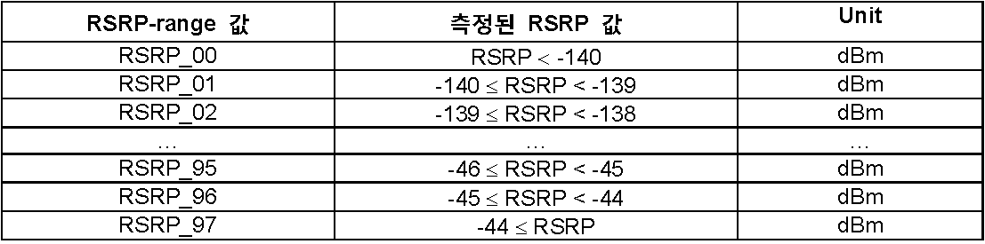
ReceivedQualWLAN_Result는 현재 무선 통신 시스템(LTE)에서 운용하는 신호 측정 방식을 통해, 현재 무선 통신 시스템의 대역 내에서 수신된 모든 수신 신호의 수신 전력 세기에 대한 현재 무선 통신 시스템의 대역 내에서 수신된 WLAN 신호의 수신 전력 세기를 측정한 값을 나타낸다. 이때, ReceivedQualWLAN_Result 값을 표현하는 방식은 특정될 수 있으며, 예컨대 RSRQ(Reference Signal Received Quality) 범위(range)로 표현되도록 특정될 수 있다. The ReceivedQualWLAN_Result is a signal of a WLAN signal received in a band of the current wireless communication system with respect to a received power intensity of all the received signals received in a band of the current wireless communication system, It represents the measured value of the received power. At this time, the manner of expressing the ReceivedQualWLAN_Result value may be specified and may be specified to be expressed by, for example, a reference signal received quality (RSRQ) range.
예를 들어, 상기 RSRQ-range는 정수 값 0 내지 34 중에 하나로 설정될 수 있으며 각 RSRQ-range 값은 [표 10]에 의해 정의된 값으로 대응된다.For example, the RSRQ-range may be set to one of integer values 0 to 34, and each RSRQ-range value corresponds to a value defined by [Table 10].

ReceivedPowerFrom_WLAN은 현재 WLAN 시스템에서 운용하는 신호 측정 방식을 통해, 현재 무선 통신 시스템(LTE)의 대역 내에서 수신된 WLAN 신호의 수신 전력 세기를 측정한 값을 나타낸다. 이때, ReceivedPowerFrom_WLAN 값을 표현하는 방식은 특정될 수 있으며, 예컨대 WLAN 시스템에서 수신 전력을 측정하는데 사용되는 값의 범위(WLAN_RP -range)로 표현되도록 특정될 수 있다. ReceivedPowerFrom_WLAN represents a value obtained by measuring a received power intensity of a WLAN signal received in a band of a current wireless communication system (LTE) through a signal measurement method operated in a current WLAN system. At this time, the manner of expressing the ReceivedPowerFrom_WLAN value may be specified, and may be specified to be expressed by, for example, a range of values (WLAN_RP-range) used for measuring the received power in the WLAN system.
ReceivedQualFrom_WLAN은 현재 WLAN 시스템에서 운용하는 신호 측정 방식을 통해, 현재 무선 통신 시스템(LTE)의 대역 내에서 수신된 모든 수신 신호의 수신 전력 세기에 대한 현재 무선 통신 시스템의 대역 내에서 수신된 WLAN 신호의 수신 전력 세기를 측정한 값을 나타낸다. 이때, ReceivedQualFrom_WLAN 값을 표현하는 방식은 특정될 수 있으며, 예컨대 WLAN 시스템에서 수신 품질을 측정하는데 사용되는 값의 범위(WLAN_RQ -range)로 표현되도록 특정될 수 있다.ReceivedQualFrom_WLAN is a signal indicating the reception of the WLAN signal received within the band of the current wireless communication system with respect to the received power intensity of all the received signals received within the band of the current wireless communication system (LTE) It represents the measured value of the power intensity. At this time, the manner of expressing the ReceivedQualFrom_WLAN value may be specified and may be specified to be expressed by, for example, a range (WLAN_RQ-range) of a value used for measuring the reception quality in the WLAN system.
UE 내 BT 시스템에 대한 필드Fields for BT systems in the UE
BT_Hopping_pattern_length는 현재 UE 내부에서 동작하는 BT 장치가 사용하는 주파수 호핑(frequency hopping) 패턴의 길이를 나타낸다. 호핑 패턴의 길이는 BT 규격에 의해 결정될 수 있으며, 예컨대 지정된 범위의 정수 값을 갖도록 할 수 있다. 반면에, BT 규격에서 사용하는 주파수 호핑 패턴을 인덱스 형식으로 지시할 수 있는 경우, 상기 BT_Hopping_pattern_length 필드는 인덱스 값을 지시하기 위한 필드로 인식되어 사용될 수도 있다. 이 경우 UE는 BT 규격에서 사용하는 인덱스와 대응되는 주파수 호핑 패턴 정보들을 미리 알고 있다.BT_Hopping_pattern_length indicates the length of a frequency hopping pattern used by the BT apparatus currently operating in the UE. The length of the hopping pattern may be determined by the BT standard, and may have an integer value within a specified range, for example. On the other hand, when the frequency hopping pattern used in the BT standard can be indicated in an index format, the BT_Hopping_pattern_length field may be recognized as a field for indicating an index value. In this case, the UE knows in advance the frequency hopping pattern information corresponding to the index used in the BT standard.
ReceivedPowerBT_Result는 현재 무선 통신 시스템(LTE)에서 운용하는 신호 측정 방식을 통해, 현재 무선 통신 시스템의 대역 내에서 수신된 BT 신호의 수신 전력 세기를 측정한 값을 나타낸다. 이때, ReceivedPowerBT_Result 값을 표현하는 방식은 특정될 수 있으며, 예컨대 RSRP-range로 표현되도록 특정될 수 있다. ReceivedPowerBT_Result represents a value obtained by measuring a received power intensity of a BT signal received in a band of a current wireless communication system through a signal measurement method operated in a current wireless communication system (LTE). At this time, the manner of expressing the ReceivedPowerBT_Result value may be specified, and may be specified to be expressed by RSRP-range, for example.
ReceivedQualBT_Result는 현재 무선 통신 시스템(LTE)에서 운용하는 신호 측정 방식을 통해, 현재 무선 통신 시스템의 대역 내에서 수신된 모든 수신 신호의 수신 전력 세기에 대한 현재 무선 통신 시스템의 대역 내에서 수신된 BT 신호의 수신 전력 세기를 측정한 값을 나타낸다. 이때, ReceivedQualBT_Result 값을 표현하는 방식은 특정될 수 있으며, 예컨대 RSRQ-range로 표현되도록 특정될 수 있다. The ReceivedQualBT_Result is a signal obtained by measuring a received BT signal received in a band of a current wireless communication system with respect to a received power intensity of all the received signals received in a band of a current wireless communication system, It represents the measured value of the received power. At this time, the manner of expressing the ReceivedQualBT_Result value may be specified, and may be specified to be expressed, for example, by an RSRQ-range.
ReceivedPowerFrom_BT는 현재 BT 시스템에서 운용하는 신호 측정 방식을 통해, 현재 무선 통신 시스템(LTE)의 대역 내에서 수신된 BT 신호의 수신 전력 세기를 측정한 값을 나타낸다. 이때, ReceivedPowerFrom_BT 값을 표현하는 방식은 특정될 수 있으며, 예컨대 BT 시스템에서 수신 전력을 측정하는데 사용되는 값의 범위(BT_RP -range)로 표현되도록 특정될 수 있다. ReceivedPowerFrom_BT is a value obtained by measuring a received power intensity of a BT signal received in a band of a current wireless communication system (LTE) through a signal measurement method operated in a current BT system. At this time, the manner of expressing the ReceivedPowerFrom_BT value may be specified, and may be specified to be expressed by, for example, a range of values (BT_RP-range) used for measuring the received power in the BT system.
ReceivedQualFrom_BT은 현재 BT 시스템에서 운용하는 신호 측정 방식을 통해, 현재 무선 통신 시스템(LTE)의 대역 내에서 수신된 모든 수신 신호의 수신 전력 세기에 대한 현재 무선 통신 시스템의 대역 내에서 수신된 BT 신호의 수신 전력 세기를 측정한 값을 나타낸다. 이때, ReceivedQualFrom_BT 값을 표현하는 방식은 특정될 수 있으며, 예컨대 BT 시스템에서 수신 품질을 측정하는데 사용되는 값의 범위(BT_RQ -range)로 표현되도록 특정될 수 있다.ReceivedQualFrom_BT indicates the reception of the BT signal received within the band of the current wireless communication system with respect to the received power intensity of all the received signals received in the band of the current wireless communication system (LTE) It represents the measured value of the power intensity. At this time, the manner of expressing the ReceivedQualFrom_BT value may be specified, and may be specified to be expressed by, for example, a range of values (BT_RQ-range) used for measuring the reception quality in the BT system.
BT_Hopping_pattern은 현재 UE 내부에서 동작하는 BT 장치가 사용하는 주파수 호핑(hopping) 패턴 정보를 나타낸다. 이때, 호핑 패턴의 길이는 BT 규격에 따라 결정될 수 있으며, BT_Hopping_pattern가 나타내는 BT 장치의 주파수 호핑 패턴은 비트맵으로 표현될 수 있다. 예를 들어, 비트정보가 '1'인 경우 미리 정해진 주파수 대역만큼 + 방향으로 호핑함을 의미하며 비트 정보가 '0'인 경우 - 방향으로 호핑함을 의미할 수 있다. 또는 2개 비트 또는 그 이상의 비트들을 하나의 호핑 정보로 판단하여 호핑 패턴을 표현할 수도 있다. BT_Hopping_pattern indicates frequency hopping pattern information used by the BT device currently operating in the UE. At this time, the length of the hopping pattern may be determined according to the BT standard, and the frequency hopping pattern of the BT device indicated by BT_Hopping_pattern may be expressed by a bitmap. For example, if the bit information is '1', it means hopping in the + direction by a predetermined frequency band, and if the bit information is '0', it means hopping in the direction. Alternatively, two or more bits may be determined as one hopping information to represent a hopping pattern.
예를 들어, 2개의 비트들을 하나의 호핑 정보로 판단하는 경우, 호핑을 4단계로 표현하는 것이 가능하며 (예를 들어 [00, 01, 10, 11] = {-2, -1, 1, 2}) 4개의 비트들을 하나의 호핑 정보로 판단하는 경우에는 호핑을 16단계로 표현하는 것이 가능하다. 상기 비트들에 대한 호핑 정보는 현재 ICO가 발생할 수 있는 UE들이 존재하고 면허 대역을 사용하는 무선 통신 시스템(LTE)에서 BT 규격을 참고하여 독자적으로 설정할 수 있다. 반면에, BT 규격에서 사용하는 주파수 호핑 패턴을 인덱스 형식으로 지시할 수 있는 경우, 상기 BT_Hopping_pattern 필드는 사용되지 않는다.For example, when two bits are judged as one hopping information, it is possible to express hopping in four stages (for example, [00, 01, 10, 11] = {-2, -1, 2}) When four bits are determined as one hopping information, hopping can be expressed in 16 steps. The hopping information for the bits can be independently established by referring to the BT standard in a wireless communication system (LTE) in which there are UEs in which ICO can occur and the license band is used. On the other hand, when the frequency hopping pattern used in the BT standard can be indicated in an index format, the BT_Hopping_pattern field is not used.
UE 내 GPS 시스템에 대한 필드Fields for the GPS system in the UE
ReceivedPowerGPS_Result는 현재 무선 통신 시스템(LTE)에서 운용하는 신호 측정 방식을 통해, 현재 무선 통신 시스템의 대역 내에서 수신된 GPS 신호의 수신 전력 세기를 측정한 값을 나타낸다. 이때, ReceivedPowerGPS_Result 값을 표현하는 방식은 특정될 수 있으며, 예컨대 RSRP-range로 표현되도록 특정될 수 있다. ReceivedPowerGPS_Result represents a value obtained by measuring a received power intensity of a GPS signal received in a band of a current wireless communication system through a signal measuring method operated in a current wireless communication system (LTE). At this time, the manner of expressing the ReceivedPowerGPS_Result value may be specified, and may be specified to be expressed by RSRP-range, for example.
ReceivedQualGPS_Result는 현재 무선 통신 시스템(LTE)에서 운용하는 신호 측정 방식을 통해, 현재 무선 통신 시스템의 대역 내에서 수신된 모든 수신 신호의 수신 전력 세기에 대한 현재 무선 통신 시스템의 대역 내에서 수신된 GPS 신호의 수신 전력 세기를 측정한 값을 나타낸다. 이때, ReceivedQualGPS_Result 값을 표현하는 방식은 특정될 수 있으며, 예컨대 RSRQ-range로 표현되도록 특정될 수 있다. The ReceivedQualGPS_Result is a signal of a GPS signal received within the band of the current wireless communication system with respect to the received power intensity of all the received signals received in the band of the current wireless communication system through the signal measuring method operated in the current wireless communication system (LTE) It represents the measured value of the received power. At this time, the manner of expressing the ReceivedQualGPS_Result value may be specified, and may be specified to be expressed, for example, by an RSRQ-range.
ReceivedPowerFrom_GPS은 현재 GPS 시스템에서 운용하는 신호 측정 방식을 통해, 현재 무선 통신 시스템(LTE)의 대역 내에서 수신된 GPS 신호의 수신 전력 세기를 측정한 값을 나타낸다. 이때, ReceivedPowerFrom_GPS 값을 표현하는 방식은 특정될 수 있으며, 예컨대 WLAN 시스템에서 수신 전력을 측정하는데 사용되는 값의 범위(GPS_RP -range)로 표현되도록 특정될 수 있다. ReceivedPowerFrom_GPS is a value obtained by measuring a received power intensity of a GPS signal received in a band of a current wireless communication system (LTE) through a signal measuring method operated in the current GPS system. At this time, the manner of expressing the ReceivedPowerFrom_GPS value may be specified, and may be specified to be expressed by, for example, a range (GPS_RP-range) of a value used for measuring the received power in the WLAN system.
ReceivedQualFrom_GPS은 현재 GPS 시스템에서 운용하는 신호 측정 방식을 통해, 현재 무선 통신 시스템(LTE)의 대역 내에서 수신된 모든 수신 신호의 수신 전력 세기에 대한 현재 무선 통신 시스템의 대역 내에서 수신된 GPS 신호의 수신 전력 세기를 측정한 값을 나타낸다. 이때, ReceivedQualFrom_GPS 값을 표현하는 방식은 특정될 수 있으며, 예컨대 GPS 시스템에서 수신 품질을 측정하는데 사용되는 값의 범위(GPS_RQ -range)로 표현되도록 특정될 수 있다.The ReceivedQualFrom_GPS is a function of the reception of the GPS signal received in the band of the current wireless communication system with respect to the received power intensity of all the received signals received in the band of the current wireless communication system (LTE) It represents the measured value of the power intensity. At this time, the manner of expressing the ReceivedQualFrom_GPS value may be specified and may be specified to be expressed by, for example, a range of values (GPS_RQ-range) used for measuring the reception quality in the GPS system.
그 외의 필드Other fields
ReceivedPowerOther_Result는 어느 시스템의 송수신 장치에 의한 것인지 구분할 수 없는 간섭 전력이나 둘 이상의 송수신 장치에 의한 간섭 전력에 대한 측정값을 지시하는데 사용할 수 있다. ReceivedPowerOther_Result는 현재 무선 통신 시스템(LTE)에서 운용하는 신호 측정 방식을 통해, 현재 무선 통신 시스템의 대역 내에서 수신된 신호 중 LTE 신호를 제외한 신호의 수신 전력 세기를 측정한 값을 나타낸다. 이때, ReceivedPowerOther_Result 값을 표현하는 방식은 특정될 수 있으며, 예컨대 RSRP-range로 표현되도록 특정될 수 있다. ReceivedPowerOther_Result can be used to indicate the interference power that can not be distinguished from the transmitting / receiving device of the system or the measured value of the interference power by two or more transmitting / receiving devices. ReceivedPowerOther_Result represents a value obtained by measuring a received power intensity of a signal received in a band of a current wireless communication system excluding a LTE signal through a signal measurement method operated in a current wireless communication system (LTE). At this time, the manner of expressing the ReceivedPowerOther_Result value may be specified, and may be specified to be expressed, for example, by an RSRP-range.
ReceivedQualOther_Result는 어느 시스템의 송수신 장치에 의한 것인지 구분할 수 없는 간섭 전력이나 둘 이상의 송수신 장치에 의한 간섭 전력에 대한 측정값을 지시하는데 사용할 수 있다. ReceivedQualOther_Result는 현재 무선 통신 시스템(LTE)에서 운용하는 신호 측정 방식을 통해, 현재 무선 통신 시스템의 대역 내에서 수신된 모든 수신 신호의 수신 전력 세기에 대한 현재 무선 통신 시스템의 대역 내에서 수신된 신호 중 LTE 신호를 제외한 신호의 수신 전력 세기를 측정한 값을 나타낸다. 이때, ReceivedOtherGPS_Result 값을 표현하는 방식은 특정될 수 있으며, 예컨대 RSRQ-range로 표현되도록 특정될 수 있다.ReceivedQualOther_Result can be used to indicate the interference power that can not be distinguished from the transmitting / receiving device of the system or the measured value of the interference power by two or more transmitting / receiving devices. The ReceivedQualOther_Result is a signal received from within the band of the current wireless communication system with respect to the received power intensity of all the received signals received in the band of the current wireless communication system through the signal measurement method operated in the current wireless communication system (LTE) And the received power of the signal excluding the signal is measured. At this time, the manner of expressing the ReceivedOtherGPS_Result value may be specified, and may be specified to be expressed by, for example, the RSRQ-range.
한편, 표 8에서는 UE 내 다른 송수신 장치에 의한 간섭 전력의 영향을 측정값을 통해 지시하는 것을 설명하였으나, 이와 달리 관련된 각 필드를 조건부로 설정하여 지시할 측정값이 있는 경우에만 설정되도록 할 수도 있다.In Table 8, it is described that the influence of the interference power by the other transceiver apparatuses in the UE is indicated through the measured values. Otherwise, it may be set only when there is a measurement value to be instructed by setting each related field conditionally .
예컨대, 측정값을 나타내는 ReceivedPowerWLAN_Result 등의 필드를 조건부로 설정할 수 있다. 즉, 해당 측정을 수행하지 않은 경우, 측정값이 0인 경우 혹은 측정값이 의미 있는 임계값에 미치지 못하는 경우 등에는 대응하는 필드를 설정하지 않도록 할 수도 있다.For example, a field such as ReceivedPowerWLAN_Result indicating the measured value can be set conditionally. That is, the corresponding field may not be set when the measurement is not performed, when the measured value is zero, or when the measured value does not reach a meaningful threshold value.
또한, UE 내 특정 통신 시스템의 송수신 장치에 대한 필드, 예컨대 measResultWLAN, measResultBT, measResultGPS, measResultOther 등도 조건부로 설정되도록 할 수 있다. 즉, 해당 시스템에 대해 측정을 수행하지 않은 경우, 측정값이 0인 경우 혹은 측정값이 의미 있는 임계값에 미치지 못하는 경우 등에는 대응하는 필드를 설정하지 않도록 할 수 있다.In addition, fields for a transceiver of a specific communication system in the UE, e.g., measResultWLAN, measResultBT, measResultGPS, measResultOther, and the like can also be set conditionally. That is, the corresponding field may not be set when the measurement is not performed for the system, when the measured value is 0, or when the measured value does not reach a meaningful threshold value.
또한, UE 내 다른 통신 시스템의 송수신 장치에 대한 필드, 예컨대 measResultIDC 역시 조건부로 설정되도록 할 수 있다. 즉, UE 내 다른 통신 시스템의 송수신 장치에 의한 간섭 전력의 영향이 없는 경우나 그 영향이 의미 있는 임계치에 미치지 못하는 경우 등에는 measResultIDC가 설정되지 않도록 할 수 있다. In addition, a field for a transceiver of another communication system in the UE, e.g., measResultIDC, may also be set to conditional. That is, the measResultIDC may not be set when there is no influence of the interference power by the transmitting / receiving apparatus of another communication system in the UE, or when the influence does not reach a meaningful threshold value.
(2) UE가 logMeasReportReq를 수신한 경우(2) When the UE receives the logMeasReportReq
표 11은 본 발명이 적용되는 시스템에서 UE가 logMeasReportReq를 수신하고 이에 대한 응답으로 eNB 또는 E-UTRAN에 전송하는 무선 통신 실패에 대한 정보를 나타내는 일 실시예이다. 이때, 무선 통신 실패에 관한 정보는 UE가 MDT를 통해 로그한 정보일 수 있다. 표 11은 ICO-RLF 정보가 UE 내 다른 송수신 장치에 의한 간섭 전력의 영향이 있었는지를 보고하는 예를 나타낸 것이다.Table 11 is an embodiment showing information on a wireless communication failure in which the UE receives the logMeasReportReq in the system to which the present invention is applied and transmits the response to the eNB or the E-UTRAN in response thereto. At this time, the information on the wireless communication failure may be the information that the UE logs through the MDT. Table 11 shows an example of reporting whether ICO-RLF information is affected by interference power from other transceivers in the UE.

표 11에서는 measResultIDC를 통해 UE 내 다른 송수신 장치에 의한 간섭 전력의 영향이 있었는지 지시한다. 예컨대, measResultIDC의 값이 True이면 UE 내 다른 송수신 장치에 의한 간섭의 영향이 있는 것을 지시하고, measResultIDC의 값이 False면 UE 내 다른 송수신 장치에 의한 간섭의 영향이 없는 것을 지시하도록 할 수 있다. 이때, measResultIDC는 조건부(optional)로 추가될 수 있으며, 따라서 UE 내 다른 송수신 장치에 의한 간섭의 영향이 있는 경우에만 설정되도록 할 수도 있다.In Table 11, it is indicated through measResultIDC whether interference power is affected by other transceivers in the UE. For example, if the value of measResultIDC is True, it indicates that interference is caused by other transceivers in the UE, and if the value of measResultIDC is false, it indicates that there is no influence of interference by other transceivers in the UE. At this time, measResultIDC may be added as an optional condition, and thus may be set only when there is an influence of interference by another transceiver in the UE.
표 11의 경우와 달리, UE 내 다른 송수신 장치에 의한 간섭 전력의 영향이 있었는지를 송수신 장치별로 보고 할 수도 있다. Unlike the case of Table 11, it can be reported whether there is an influence of interference power by other transmitting / receiving devices in the UE by the transmitting / receiving devices.
표 12는 본 발명이 적용되는 시스템에서 UE가 logMeasReportReq를 수신하고 이에 대한 응답으로 eNB 또는 E-UTRAN에 전송하는 무선 통신 실패에 대한 정보를 나타내는 다른 실시예이다. 이때, 무선 통신 실패에 관한 정보는 UE가 MDT를 통해 로그한 정보일 수 있다. 표 12는 ICO-RLF 정보가 UE 내 다른 송수신 장치에 의한 별로 간섭 전력의 영향이 있었는지를 송수신 장치별로 보고하는 예를 나타낸 것이다.Table 12 is another embodiment showing information on a wireless communication failure in which the UE receives the logMeasReportReq and transmits it to the eNB or the E-UTRAN in response thereto in the system to which the present invention is applied. At this time, the information on the wireless communication failure may be the information that the UE logs through the MDT. Table 12 shows an example of how the ICO-RLF information is affected by interference power by other transceivers in the UE by the transceiver.

표 12의 RLF 보고에서는, measResultIDC 필드를 통해 UE 내 다른 송수신 장치에 의한 간섭 전력의 영향이 있었는지를 지시할 수 있다. 예컨대, measResultIDC 필드의 서브 필드를 통해서 UE 내 다른 송수신 장치에 의한 간섭 전력이 있었는지를 송수신 장치별로 지시할 수 있다. 구체적으로, 표 7에서와 같이, measResultIDC 필드의 각 서브 필드의 값이 True 인지 False인지를 통해 UE 내 다른 송수신 장치별로 간섭 전력의 영향이 있는지를 지시할 수 있다.In the RLF report of Table 12, it is possible to indicate through the measResultIDC field whether interference power has been affected by other transceivers in the UE. For example, it is possible to indicate, via the subfields of the measResultIDC field, whether interference power caused by another transceiver apparatus in the UE exists for each transceiver apparatus. Specifically, as shown in Table 7, whether the value of each sub-field of the measResultIDC field is True or False may indicate whether interference power is influenced by other transceivers in the UE.
한편, ICO-RLF 정보로서 UE 내 다른 송수신 장치에 의한 간섭 전력의 영향이 있었는지만을 보고하는 표 10의 경우와 달리, UE 내 다른 송수신 장치의 수신 전력 및/또는 간섭 전력 값을 모두 보고할 수도 있다. On the other hand, unlike the case of Table 10, which reports only the influence of the interference power by other transmitting / receiving devices in the UE as ICO-RLF information, it is also possible to report all received power and / or interference power values of other transmitting / have.
표 13은 본 발명이 적용되는 시스템에서 UE가 logMeasReportReq를 수신하고 이에 대한 응답으로 eNB 또는 E-UTRAN에 전송하는 무선 통신 실패에 대한 정보를 나타내는 다른 실시예이다. 표 13은 ICO-RLF 정보가 UE 내 다른 송수신 장치의 수신 전력 및/또는 간섭 전력 값을 포함하는 예를 나타낸 것이다.Table 13 shows another embodiment of the present invention in which the UE receives the logMeasReportReq and transmits information to the eNB or the E-UTRAN in response thereto in the system in which the present invention is applied. Table 13 shows an example in which ICO-RLF information includes received power and / or interference power values of other transceivers in the UE.

표 13의 RLF 보고에서도, measResultIDC 필드를 통해 UE 내 다른 송수신 장치에 의한 간섭 전력의 영향이 있었는지를 지시할 수 있다. 예컨대, measResultIDC 필드의 서브 필드를 통해서 UE 내 다른 송수신 장치에 의한 간섭 전력이 있었는지를 송수신 장치별로 지시할 수 있다. 표 13의 경우에는 표 12의 경우와 달리, 각 서브 필드가 대응하는 통신 시스템에 대한 측정 결과를 통해 해당하는 통신 시스템의 송수신 장치에 의한 간섭 전력의 영향이 있는지를 지시하도록 할 수 있다.In the RLF report of Table 13, the measResultIDC field may also indicate whether interference power has been affected by other transceivers in the UE. For example, it is possible to indicate, via the subfields of the measResultIDC field, whether interference power caused by another transceiver apparatus in the UE exists for each transceiver apparatus. In the case of Table 13, different from the case of Table 12, it is possible to indicate whether there is influence of the interference power by the transmitting / receiving apparatus of the corresponding communication system through the measurement result of the corresponding communication system in each subfield.
구체적으로 표 13의 RLF 보고에서는, measResultIDC 필드의 각 서브 필드를 통해 UE 내 다른 송수신 장치별 측정 값을 지시하도록 할 수 있다. Specifically, in the RLF report of Table 13, it is possible to indicate the measurement values for different transceivers in the UE through each subfield of the measResultIDC field.
예컨대, measResultIDC 필드의 서브 필드인 measResultWLAN가 하위 서브 필드인 MeasResultWLAN을 지시하여, MeasResultWLAN의 서브 필드인 ReceivedPowerWLAN_Result, ReceivedQualWLAN_Result, ReceivedPowerFrom_WLAN, ReceivedQualFrom_WLAN 등을 통해 측정 결과를 지시하도록 할 수 있다. For example, measResultWLAN, which is a subfield of measResultIDC field, indicates MeasResultWLAN, which is a lower subfield, and can indicate measurement results through ReceivedPowerWLAN_Result, ReceivedQualWLAN_Result, ReceivedPowerFrom_WLAN, ReceivedQualFrom_WLAN, etc., which are subfields of MeasResultWLAN.
마찬가지로, measResultIDC 필드의 서브 필드인 measResultBT가 하위 서브 필드인 MeasResultBT을 지시하여, MeasResultBT의 서브 필드인 ReceivedPowerBT_Result, ReceivedQualBT_Result, ReceivedPowerFrom_BT, ReceivedQualFrom_BT, BT_Hopping_pattern_length, BT_Hopping_Pattern 등을 통해 측정 결과를 지시하도록 할 수 있고, measResultIDC 필드의 서브 필드인 measResultGPS가 하위 서브 필드인 MeasResultGPS을 지시하여, MeasResultGPS의 서브 필드인 ReceivedPowerGPS_Result, ReceivedQualGPS_Result, ReceivedPowerFrom_GPS, ReceivedQualFrom_GPS 등을 통해 측정 결과를 지시하도록 할 수 있다.MeasResultBT, which is a subfield of measResultIDC field, indicates MeasResultBT, which is a lower subfield, and can indicate measurement results through ReceivedPowerBT_Result, ReceivedQualBT_Result, ReceivedPowerFrom_BT, ReceivedQualFrom_BT, BT_Hopping_pattern_length, BT_Hopping_Pattern etc. of MeasResultBT, MeasResultGPS which is a subfield indicates MeasResultGPS which is a lower subfield and can indicate the measurement result through ReceivedPowerGPS_Result, ReceivedQualGPS_Result, ReceivedPowerFrom_GPS, ReceivedQualFrom_GPS, etc. which are subfields of MeasResultGPS.
이때, 어느 시스템의 송수신 장치에 의한 것인지 구분할 수 없는 간섭 전력이나 둘 이상의 송수신 장치에 의한 간섭 전력에 대해서는, measResultIDC 필드의 서브 필드로서 measResultOther 가 하위 서브 필드인 MeasResultOther를 지시하여, MeasResultOther의 서브 필드인 ReceivedPowerOther_Result, ReceivedQualOther_Result 등을 통해 측정 결과를 지시하도록 할 수 있다.At this time, as to the interference power which can not be distinguished by the transmission / reception device of the system or the interference power by two or more transmission / reception devices, measResultOther as the subfield of the measResultIDC field indicates MeasResultOther which is the lower subfield, and ReceivedPowerOther_Result , ReceivedQualOther_Result, or the like.
표 13에 있어서, UE 내의 WLAN 송수신 장치에 관하여 측정된 수신 전력 및/또는 간섭 전력을 나타내는 필드는 표 8의 각 필드와 동일하게 정의될 수 있다.In Table 13, the field indicating the measured received power and / or interference power with respect to the WLAN transceiver in the UE may be defined the same as each field in Table 8. [
한편, 표 6 내지 8 및 표 11 내지 표 13의 실시예에서 UE 내 다른 송수신 장치별로, 일부 송수신 장치에 대해서는 간섭 전력의 영향이 있는지 만을 지시하고, 일부 송수신 장치에 대해서는 수신 전력과 간섭 전력의 값을 지시하도록 RLF 보고를 구성할 수도 있다. 또한, UE 내 송수신 장치의 수신 전력과 간섭 전력 중 어느 하나만을 지시하도록 할 수도 있고, 일부 송수신 장치에 대해서는 수신 전력만을 지시하고 다른 일부 송수신 장치에 대해서는 간섭 전력만을 지시하며, 나머지 송수신 장치에 대해서는 수신 전력과 간섭 전력을 모두 지시하도록 RLF 보고를 구성할 수도 있다.On the other hand, in the embodiments of Tables 6 to 8 and Tables 11 to 13, only the effect of interference power is shown for some of the transceivers in the UE, and for some transceivers, the value of the received power and the interference power Lt; RTI ID = 0.0 > RLF < / RTI > In addition, only one of the reception power and the interference power of the transmission / reception device in the UE may be indicated, only the reception power may be indicated for some transmission / reception devices, only the interference power may be indicated for some other transmission / reception devices, The RLF report may be configured to indicate both power and interference power.
또한, 표 6 내지 8 및 표 11 내지 표 13의 실시예에서는, rlf-ReportReq 또는 logMeasReportReq를 받은 경우에 ICO-RLF 정보를 전송하는 것으로 설명하였으나, 이에 한하지 않고, UE 정보 제공 요구 메시지상에 ICO-RLF 정보를 구체적으로 요구하는 필드가 존재하고, 해당 필드를 통해 ICO-RLF 정보가 요구된 경우에만 ICO-RLF 정보를 UE가 UE 정보 제공 응답 메시지에 포함하여 전송하도록 할 수도 있다.In the embodiments of Tables 6 to 8 and Tables 11 to 13, it has been described that ICO-RLF information is transmitted when rlf-ReportReq or logMeasReportReq is received. However, the present invention is not limited to this, The UE may transmit the ICO-RLF information by including it in the UE information providing response message only when there is a field specifically requesting the -RLF information and ICO-RLF information is requested through the corresponding field.
도 11은 본 발명이 적용되는 시스템에서 수행되는 RLF 보고 절차를 개략적으로 설명하는 순서도이다.11 is a flowchart schematically illustrating an RLF reporting procedure performed in a system to which the present invention is applied.
도 11을 참조하면, UE와 eNBRel 사이에 RLF(RLF)가 발생한다(S1110). 이때, RLF는 인접한 (이종) 셀로부터의 간섭에 의한 것일 수도 있고, UE 내 다른 송수신 장치에 의한 간섭의 영향 때문에 발생한 것일 수도 있다. 또한 RLF는 네트워크 자체의 문제에 기반한 것일 수도 있다.Referring to FIG. 11, an RLF (RLF) is generated between the UE and the eNB Rel (S1110). At this time, the RLF may be due to interference from adjacent (heterogeneous) cells or may be caused by the influence of interference by other transceivers in the UE. RLF may also be based on the problem of the network itself.
UE는 셀 탐색을 통해 RRC 연결을 재설정하기에 적합한 셀을 찾는다.The UE searches for a cell suitable for re-establishing the RRC connection through cell search.
RRC 연결을 재설정하기에 적합한 셀로서 eNBCON을 선택한 경우에, UE는 eNBCON에 RRC 연결 재설정 메시지를 전송한다(S1120). 성공적인 핸드오버 이후에 일시적인 RLF가 있었던 경우에는 eNBCON가 UE와의 사이에서 RLF를 발생시킨 eNB일 수도 있다. UE로부터 eNBCON으로 전송되는 RRC 연결 재설정 메시지는 UE ID, PCI 등의 정보와 함께 원인 값으로서 RLF 정보를 포함할 수 있다. If eNB CON is selected as a cell suitable for re-establishing the RRC connection, the UE transmits an RRC connection re-establishment message to the eNB CON (S1120). If there is a temporary RLF after a successful handover, the eNB CON may be the eNB that generated the RLF with the UE. The RRC connection reestablishment message transmitted from the UE to the eNB CON may include RLF information as a cause value together with information such as UE ID, PCI, and the like.
eNBCON는 RRC 연결 재설정 요구 메시지를 수신하고, RRC 연결 재설정 메시지를 전송한다(S1130). The eNB CON receives the RRC connection re-establishment request message and transmits an RRC connection re-establishment message (S1130).
UE는 RRC 연결 재설정 메시지를 수신하고, RRC 연결 재설정 메시지에 포함된 정보를 기반으로 RRC 연결을 재설정하며, RRC 연결 재설정 완료 메시지를 eNBCON에 전송한다(S1140).The UE receives the RRC connection re-establishment message, re-establishes the RRC connection based on the information included in the RRC connection re-establishment message, and transmits an RRC connection re-establishment completion message to the eNB CON (S1140).
상술한 RRC 연결 재설정 절차를 통해서 eNBCON은 RRC 연결 재설정 요구 메시지에 원인 값으로 포함된 RLF 정보를 획득할 수 있다.Through the above-described RRC connection re-establishment procedure, the eNB CON can acquire the RLF information included as the cause value in the RRC connection re-establishment request message.
또한, eNBCON을 통해서, E-UTRAN은 필요한 정보를 획득하기 위해 UE에 UE 정보 제공 요구 메시지를 전송할 수도 있다(S1150). UE 정보 제공 요구 메시지는 rlf-ReportReq, logMeasReportReq 등과 같이 RLF 정보를 요구하는 필드를 포함할 수 있다.In addition, through the eNB CON , the E-UTRAN may transmit a UE information providing request message to the UE to acquire necessary information (S1150). The UE information providing request message may include a field for requesting RLF information such as rlf-ReportReq, logMeasReportReq, and the like.
UE는 UE 정보 제공 요구 메시지에 포함된 rlf-ReportReq, logMeasReportReq 등을 확인하고 대응하는 RLF 정보를 UE 정보 제공 응답 메시지에 포함시켜 eNBCON(E-UTRAN)에 전달할 수 있다(S1160).The UE confirms rlf-ReportReq and logMeasReportReq included in the UE information providing request message, and transmits the corresponding RLF information to the eNB CON (E-UTRAN) in step S1160.
RRC 연결 재설정 절차 또는 UE 정보 제공 절차를 통해 RLF 정보를 획득한 eNBCON(E-UTRAN)는 획득한 RLF 정보를 관련된 eNB(eNBRel)에 전달한다(S1170). 이때, RLF 정보는 X2 인터페이스를 통해 전달될 수 있다. CON eNB (E-UTRAN) obtaining the RLF information through the RRC connection procedure to reset or UE information providing procedure passes the acquired information to the RLF eNB (eNB Rel) associated (S1170). At this time, the RLF information can be transmitted through the X2 interface.
eNBRel는 PCI 등을 통해 확인할 수 있는 UE의 이전 셀 또는 이전 eNB일 수도 있고, 이 경우에 RLF 정보는 RLF 지시(RLF Indication)을 통해 eNBRel에 전달될 수 있다.The eNB Rel may be a previous cell of the UE or a previous eNB that can be identified through PCI or the like. In this case, the RLF information may be transmitted to the eNB Rel via the RLF indication (RLF Indication).
또한, RLF 정보는 핸드오버 보고(handover report)를 통해 eNBRel에 전달될 수도 있으며, 이 경우 eNBRel은 PCI 등을 통해 파악되는 UE의 원 소스 eNB, 소스 셀, 타겟 셀 등이 될 수 있다.In addition, the RLF information may be transmitted to the eNB Rel via a handover report. In this case, the eNB Rel may be a source eNB of the UE, a source cell, a target cell, etc.,
한편, eNBCON은 RLF가 네트워크의 문제에 기반한 것이 아닌 기기 내 공존 간섭에 의한 것인 경우에는, 해당 RLF 정보가 eNBRel에 필요한 정보라고 판단된 시기 또는 경우에만 RLF 정보를 eNBRel에 전송할 수도 있다. On the other hand, eNB CON is RLF is in the case of that obtained from the device in co-interference, rather than based on the problem of the network, may send an RLF information that RLF information when it is determined that the information required for the eNB Rel or only when the eNB Rel .
도 12는 본 발명이 적용되는 시스템에서 RLF를 겪은 UE가 수행하는 RLF 정보의 보고 절차를 개략적으로 설명하는 순서도이다.12 is a flowchart schematically illustrating a procedure of reporting RLF information performed by a UE that has undergone RLF in a system to which the present invention is applied.
도 12를 참조하면, UE는 우선 RLF가 발생한 것을 검지(detect)한다(S1210). Referring to FIG. 12, the UE detects that an RLF has occurred (S1210).
이때, UE는 RLF 정보를 획득하여 이를 기록할 수 있다(S1220). UE는 획득한 RLF 정보를 VarRLF-Report의 각 필드에 저장할 수 있다. UE가 획득한 RLF 정보가 MDT를 수행하는 과정에서 측정된 것이라면, UE는 MDT에 의해 작성된 로그를 VarLogMeasReport의 각 필드에 저장할 수 있다. At this time, the UE may acquire RLF information and record the RLF information (S1220). The UE may store the acquired RLF information in each field of the VarRLF-Report. If the RLF information obtained by the UE is measured in the course of performing the MDT, the UE may store the log created by the MDT in each field of the VarLogMeasReport.
UE는 eNB를 통해 RLF 정보를 전송해 달라는 요구를 수신한다(S1230). 이때, eNB는 RLF 후 RRC 연결이 재설정된 eNB일 수 있다. 또한, RLF 정보를 전송해 달라는 요구는 E-UTRAN으로부터의 UE 정보 제공 요구 메시지에 포함되어 전송될 수 있다. The UE receives a request to transmit RLF information through the eNB (S1230). At this time, the eNB may be the eNB with the RRC connection reset after the RLF. In addition, the request to transmit the RLF information may be transmitted in the UE information providing request message from the E-UTRAN.
UE는 전송할 RLF 보고를 구성한다(S1260). 이때, UE는 네트워크로 인한 RLF의 원인뿐만 아니라, 기기 내 공존 간섭에 의한 RLF의 원인도 포함하여 RLF 보고를 구성할 수 있다. The UE configures an RLF report to be transmitted (S1260). At this time, the UE can configure the RLF report including not only the cause of the RLF due to the network but also the cause of the RLF due to intra-device coexistence interference.
기기 내 공존 간섭에 관한 정보를 포함하는 경우에, UE는 기기 내 공존 간섭에 관한 정보가 기기 내 공존 간섭에 의한 영향이 있었다는 정보만을 포함하도록 할 수도 있고, UE 내 어떤 시스템의 송수신 장치로부터 간섭이 있었는지를 지시하는 정보를 포함할 수도 있으며, UE 내 각 시스템별로 간섭에 관한 측정 결과를 포함하도록 할 수도 있다. In the case where the UE includes information on coexistence interference in the UE, the UE may include only information indicating that coexistence interference in the UE has been affected by intra-UE coexistence interference, and interference from a transmission / , And may include measurement results on interference for each system in the UE.
RLF 보고가 어떤 정보를 포함할 것인지에 관하여는 UE에 미리 설정되어 있을 수도 있고 상위 계층 시그널링을 통해 전달될 수도 있다. 또한, eNB 또는 E-UTRAN으로부터 UE 정보 제공 요구 메시지 등을 통해 필요한 정보를 지정할 수도 있다.It may be preset in the UE as to what information the RLF report will contain or may be delivered via higher layer signaling. Further, it is also possible to designate necessary information through the UE information providing request message from the eNB or the E-UTRAN.
UE는 구성된 RLF 정보를 eNB(E-UTRAN)에 전송한다(S1250). 이때 RLF 정보는 eNB를 통해 E-UTRAN 측으로 전달될 수 있다. UE가 RLF에 대한 정보를 전송해 달라는 요구를 UE 정보 제공 요구 메시지를 통해 수신한 경우에는, RLF 정보를 UE 정보 제공 응답 메시지에 포함하여 전송할 수 있다.The UE transmits the configured RLF information to the eNB (E-UTRAN) (S1250). At this time, the RLF information may be transmitted to the E-UTRAN side through the eNB. When the UE receives a request to transmit information on the RLF through the UE information providing request message, the UE can transmit the RLF information by including it in the UE information providing response message.
또한, UE가 RLF 정보를 전송하는 eNB는 RRC 연결을 재설정하고자 하는 eNB일 수 있다. 이 경우에 UE는 eNB로부터의 요구, 즉 S1230 단계를 거치지 않고, RLF 정보를 RRC 연결 재설정 요구 메시지에 원인값으로 포함시켜 전송할 수 있다.Also, the eNB to which the UE transmits the RLF information may be an eNB that desires to reset the RRC connection. In this case, the UE may transmit the RLF information by including the RLF information as a cause value in the RRC connection re-establishment request message without going through the request from the eNB, that is, step S1230.
한편, 여기서는 UE가 UE 정보 제공 요구 메시지를 수신하고 RLF 보고를 구성하는 것으로 설명하였으나, 본 발명은 이에 한정되지 않으며, RLF 보고는 UE 정보 제공 요구 메시지가 수신되지 않더라도, RLF를 감지한 UE에 의해 작성될 수 있다. 이 경우에, UE는 UE 정보 제공 요구 메시지에 대한 응답으로 혹은 RRC 연결 재설정 요구 메시지에 포함시켜, 작성된 RLF 보고를 전송할 수 있다.Herein, it is described that the UE receives the UE information providing request message and configures the RLF report. However, the present invention is not limited to this, and the RLF reporting may be performed by the UE that has detected the RLF, Can be created. In this case, the UE may transmit the generated RLF report in response to the UE information providing request message or in the RRC connection re-establishment request message.
도 13은 본 발명이 적용되는 시스템에서 RLF 정보를 수신하는 eNB가 수행하는 동작을 개략적으로 설명하는 순서도이다.13 is a flowchart schematically illustrating an operation performed by an eNB receiving RLF information in a system to which the present invention is applied.
도 13을 참조하면, eNB는 무선 통신 실패가 발생한 UE에 무선 통신 실패에 관한 정보 요구 메시지를 전송할 수 있다(S1310). 무선 통신 실패가 발생한 UE와 RRC 연결을 재설정한 eNB는 UE 정보 제공 요구 메시지 등을 통하여 무선 통신 실패에 관한 정보를 요구할 수 있다.Referring to FIG. 13, the eNB may transmit an information request message regarding a failure of wireless communication to a UE in which a wireless communication failure occurs (S1310). The eNB that has reconnected the RRC connection with the UE where the radio communication failure has occurred may request information on the radio communication failure through the UE information providing request message or the like.
eNB는 UE로부터 RLF 보고를 수신한다(S1320). UE로부터 전송된 RLF 보고는 UE 정보 제공 요구 메시지에 대한 응답으로서, UE 정보 제공 응답 메시지에 포함되어 전송될 수 있다. The eNB receives the RLF report from the UE (S1320). The RLF report transmitted from the UE may be included in the UE information providing response message and transmitted as a response to the UE information providing request message.
한편, UE는 UE 정보 제공 요구 메시지의 수신 없이도 RLF 정보를 보고 할 수 있다. 즉, eNB는 S1310 단계를 거치지 않고 UE로부터 RLF 정보를 수신할 수 있는데, 이 경우 RLF 정보는 UE로부터의 RRC 연결 재설정 요구 메시지에 RRC 연결 재설정 요구에 대한 원인값으로 포함되어 전송될 수 있다. Meanwhile, the UE can report the RLF information without receiving the UE information providing request message. That is, the eNB may receive the RLF information from the UE without going through step S1310. In this case, the RLF information may be transmitted as a cause value for the RRC connection re-establishment request in the RRC connection re-establishment request message from the UE.
eNB는 UE로부터 수신한 RLF 정보를 분석한다(S1330). eNB는 RLF가 발생한 서빙 셀의 ID를 확인할 수 있으며, RLF의 원인을 확인할 수 있다.The eNB analyzes the RLF information received from the UE (S1330). The eNB can confirm the ID of the serving cell in which the RLF is generated, and can confirm the cause of the RLF.
eNB는 RLF 정보를 관련 eNB에 전송한다(S1340). 관련 eNB는 PCI 등을 통해 확인할 수 있는 UE의 이전 셀 또는 이전 eNB일 수도 있고, 이 경우에 RLF 정보는 RLF 지시(RLF Indication)을 통해 전달될 수 있다. 또한, RLF 정보는 핸드오버 보고(handover report)를 통해 전달될 수도 있으며, 이 경우 관련 eNB는 PCI 등을 통해 파악되는 UE의 원 소스 eNB, 소스 셀, 타겟 셀 등이 될 수 있다.The eNB transmits the RLF information to the associated eNB (S1340). The associated eNB may be the previous cell of the UE or a previous eNB that can be identified via PCI or the like, in which case the RLF information may be delivered via the RLF indication (RLF Indication). In addition, the RLF information may be transmitted through a handover report. In this case, the associated eNB may be a source eNB of the UE, a source cell, a target cell, etc.,
한편, eNB는 RLF가 네트워크의 문제에 기반한 것이 아닌 기기 내 공존 간섭에 의한 것인 경우에는, 해당 RLF 정보가 관련 eNB에 필요한 정보라고 판단된 시기 또는 경우에만 RLF 정보를 관련 eNB에 전송할 수도 있다.On the other hand, when the eNB is based on intra-device coexistence interference not based on the problem of the network, the eNB may transmit the RLF information to the related eNB only when the corresponding RLF information is determined to be necessary information for the related eNB.
도 14는 본 발명이 적용되는 시스템에서 RLF가 발생했던 eNB가 RLF 정보를 기반으로 수행하는 동작을 개략적으로 설명하는 순서도이다.FIG. 14 is a flowchart schematically illustrating an operation performed by an eNB that has generated an RLF based on RLF information in a system to which the present invention is applied.
도 14를 참조하면, RLF가 발생했던 eNB는 RLF 정보를 수신한다(S1410). RLF 정보는 RLF가 발생했던 UE와 새롭게 RRC 연결을 재설정한 eNB로부터 RLF 지시 또는 핸드오버 보고 등을 통해 수신할 수 있다.Referring to FIG. 14, the eNB in which the RLF has occurred receives the RLF information (S1410). The RLF information can be received from the UE where the RLF has occurred and the eNB that has newly reconfigured the RRC connection through RLF indication or handover report.
RLF가 발생했던 eNB는 RLF 정보를 분석해서 RLF의 원인을 분석할 수 있다(S1420). The eNB in which the RLF has occurred can analyze the cause of the RLF by analyzing the RLF information (S1420).
RLF가 발생했던 eNB는 분석한 RLF의 원인을 기반으로 RLF의 원인을 개선한다(S1430). RLF는 여러 가지 원인에 기반할 수 있다. RLF의 원인이 셀 간 간섭 등과 같은 네트워크에 기인한 원인인 경우에, eNB는 해당 원인을 반영하여 시스템이 운용되도록 할 수 있다. 또한, RLF의 원인이 UE 내부의 원인 예컨대 기기 내 공존 간섭 등인 경우에는 핸드오버 등을 통해 해당 UE와 다시 RRC 연결을 설정하는 경우에 해당 UE에 관한 정보로서 RLF의 원인을 활용할 수 있다.The eNB in which the RLF has occurred improves the cause of the RLF based on the cause of the analyzed RLF (S1430). RLF can be based on several causes. If the cause of the RLF is caused by a network such as inter-cell interference, the eNB can cause the system to operate by reflecting the cause. When the cause of the RLF is a cause of the UE, for example, intra-device coexistence interference, when the RRC connection is established again with the corresponding UE through handover or the like, the cause of the RLF can be utilized as information on the UE.
도 15는 본 발명이 적용되는 시스템에서 UE의 구성을 개략적으로 설명하는 블록도이다.15 is a block diagram schematically illustrating a configuration of a UE in a system to which the present invention is applied.
도 15를 참조하면, UE(1500)는 RF부(1510), 메모리(1520), 프로세서(1530)을 포함한다.Referring to FIG. 15, a
UE(1500)는 RF부(1510)을 통해서 필요한 정보를 송수신한다. 실제로 UE(1500)는 다양한 통신 시스템을 지원할 수 있는데, RF부(1510)는 UE(1500)가 다양한 통신 시스템을 이용할 수 있도록 각각의 시스템에 대한 RF부를 포함할 수 있다. 예컨대, RF부(1510)는 LTE 시스템에 대한 RF부(1540), WLAN 시스템에 대한 RF부(1550), BT 시스템에 대한 RF부(1560), GPS에 대한 RF부(1570) 등을 포함할 수 있다. The
각각의 시스템에 대한 RF부(1540~1560)는 각 시스템에서 규정된 대역을 이용하지만, 기기 내 공존 간섭에 관하여 상술한 바와 같이 동일 UE 내에서 서로 간에 간섭을 일으킬 수도 있다. The RF units 1540-1560 for each system use the defined bands in each system, but may also interfere with each other within the same UE as described above for coexistence interference in the equipment.
메모리(1520)는 UE(1500)가 통신을 수행하는데 필요한 정보를 저장한다. 예컨대, 메모리(1520)는 측정을 통한 네트워크 상태 또는 채널 상태에 대한 정보를 저장하며, MDT를 통해 작성한 로그를 저장한다. 또한, 메모리(1520)는 RLF가 발생한 경우에, 이에 대한 정보를 저장할 수 있다. RLF에 대한 정보가 MDT를 통해 측정된 경우에는 RLF에 대한 정보를 로그로 작성하여 저장할 수 있다.The
프로세서(1530)는 측정부(1580)와 제어부(1590)를 포함한다. 프로세서(1530)는 RF부(1510) 및 메모리(1520)와 연결되어, 제어부(1590)를 통해 이들을 제어할 수 있다.The
측정부(1580)는 네트워크 상태 또는 채널 상태 등을 판단하기 위한 측정을 수행한다. UE(1500)가 지원하는 각 통신 시스템은, 각 통신 시스템별 측정 방식을 규정하고 있다. 측정부(1580)는 각 통신 시스템별 측정 방식에 따라서 각 RF부(1540~1560)을 통해 수신되는 신호들의 세기를 측정할 수 있다. 또한, 측정부(1580)는 기기 내 공존 간섭에 의한 영향을 판단하기 위해, 해당 시스템의 대역 내에서 수신되는 이종 시스템의 신호를 측정할 수도 있다. 예컨대, 해당 시스템의 대역 내에서 수신되는 신호에서 해당 대역의 정해진 수신 신호를 제거하는 방식으로, 이종 시스템의 영향을 측정할 수도 있다. The
측정부(1580)는 RLF가 발생한 경우에, UE 또는 시스템의 상황을 측정할 수 있고, 측정부(1580)의 측정 결과는 메모리(1520)에 저장된다. The
제어부(1590)는 측정부(1580)의 측정 결과 또는 무선 통신 상황을 판단하여 RLF가 발생하였는지 판단할 수 있다. 제어부(1590)는 RLF 보고를 작성할 수 있다. 이때, 제어부(1590)는 측정부(1580)의 측정 결과를 기반으로 RLF 보고를 작성할 수 있다. The
제어부(1590)는 UE 정보 제공 요구 메시지에 대한 응답으로, 혹은 RRC 연결 재설정 요구 메시지에 포함시켜 RLF 보고를 RF부(1510)를 통해 전송할 수 있다. RLF 보고는 eNB로부터 수신한 RLF 정보 요구에 대응해서 구성될 수도 있고, 미리 정해진 방식에 따라서 구성될 수도 있다. 예컨대, 제어부(1590)는 기기 내 공존 간섭에 대하여, 기기 내 공존 간섭의 유무에 대한 정보만을 포함시킬 것인지, 시스템별 간섭의 유무에 대한 정보를 포함시킬 것인지, 시스템별 측정값을 포함시킬 것인지를 eNB로부터의 요구에 대응하여 혹은 미리 정해진 설정에 따라서 결정하고, 이에 따라서 RLF 보고를 작성할 수 있다. The
도 16은 본 발명이 적용되는 시스템에서 eNB의 구성을 개략적으로 설명하는 블록도이다.16 is a block diagram schematically illustrating the configuration of an eNB in a system to which the present invention is applied.
도 16을 참조하면, eNB(1600)는 RF부(1610), 메모리(1620), 프로세서(1630)를 포함한다.Referring to FIG. 16, the
eNB(1600)는 RF부(1610)를 통해서 필요한 정보를 송수신한다. The
메모리(1620)는 시스템 운용에 필요한 정보를 저장한다. 예컨대, 메모리(1620)는 RRC 연결 재설정을 위한 정보를 저장할 수 있다. RRC 연결 재설정을 위한 정보는 RRC 연결을 재설정하고자 하는 UE의 이전 셀의 ID, PCI, RRC 연결 재설정에 대한 원인값으로서 RLF 정보를 포함할 수 있다. 또한, 메모리(1620)는 UE 정보 제공 요구 메시지에 대한 응답으로서 수신한 UE 정보 제공 응답 메시지 내의 RLF 정보를 저장할 수 있다.The
프로세서(1630)는 UE와의 사이에서 RRC 연결 재설정 절차를 수행할 수 있다. 프로세서(1630)는 UE로부터 수신한 해당 UE의 RLF 정보를 분석하고, 이를 관련 eNB에 전송할 수 있다. 또한, 프로세서(1630)는 자신과의 사이에서 RLF가 발생했던 UE의 RLF 정보를 수신한 경우에는, 해당 정보를 분석하고 RLF의 원인을 개선할 수 있다. 프로세서(1630)은 E-UTRAN으로부터 UE 정보 제공 요구가 있는 경우, UE에 정보 제공 요구 메시지를 전송할 수도 있다.
이상의 설명은 본 발명의 기술 사상을 예시적으로 설명한 것에 불과한 것으로서, 본 발명이 속하는 기술 분야에서 통상의 지식을 가진 자라면 본 발명의 본질적인 특성에서 벗어나지 않는 범위에서 다양한 수정 및 변형이 가능할 것이다. 따라서, 본 발명에 개시된 실시 예들은 본 발명의 기술 사상을 한정하기 위한 것이 아니라 설명하기 위한 것이고, 이러한 실시 예에 의하여 본 발명의 기술 사상의 범위가 한정되는 것은 아니다. 본 발명의 보호 범위는 아래의 청구범위에 의하여 해석되어야 하며, 그와 동등한 범위 내에 있는 모든 기술 사상은 본 발명의 권리범위에 포함되는 것으로 해석되어야 할 것이다. The foregoing description is merely illustrative of the technical idea of the present invention, and various changes and modifications may be made by those skilled in the art without departing from the essential characteristics of the present invention. Therefore, the embodiments disclosed in the present invention are intended to illustrate rather than limit the scope of the present invention, and the scope of the technical idea of the present invention is not limited by these embodiments. The scope of protection of the present invention should be construed according to the following claims, and all technical ideas within the scope of equivalents should be construed as falling within the scope of the present invention.
Claims (12)
상기 무선 링크 실패에 관한 무선 링크 실패 보고를 구성하는 단계; 및
상기 무선 링크 실패 보고를 전송하는 단계를 포함하며,
상기 무선 링크 실패 보고는 상기 무선 링크 실패에 대하여 기기 내 공존 간섭에 의한 영향이 있었는지에 관한 정보를 포함하고,
상기 무선 링크 실패 보고는 기기 내 공존 간섭을 발생시킨 통신 시스템을 지시하는 정보를 포함하는 것을 특징으로 하는 단말의 무선 링크 실패 보고 방법.Detecting a radio link failure;
Configuring a radio link failure report on the radio link failure; And
And transmitting the radio link failure report,
Wherein the radio link failure report includes information on whether the radio link failure has been affected by intra-device coexistence interference,
Wherein the radio link failure report includes information indicating a communication system in which coexistence interference has occurred in the device.
상기 무선 링크 실패가 발생한 셀에 상기 무선 링크 실패에 관한 정보를 전송하는 단계를 포함하며,
상기 무선 링크 실패가 발생한 셀은 상기 무선 링크 실패 보고를 기반으로 판단하고,
상기 무선 링크 실패 보고는 기기 내 공존 간섭을 발생시킨 통신 시스템을 지시하는 정보를 포함하는 것을 특징으로 하는 기지국의 무선 링크 실패 보고 처리 방법.Receiving a radio link failure report; And
And transmitting information about the radio link failure to a cell where the radio link failure occurred,
Wherein the cell in which the radio link failure occurs is determined based on the radio link failure report,
Wherein the radio link failure report includes information indicating a communication system in which coexistence interference has occurred in the device.
상기 무선 링크 실패가 발생한 셀이 상기 기기 내 공존 간섭에 관한 정보를 필요로 하는 경우에만 상기 단말의 기기 내 공존 간섭 정보를 전송하는 것을 특징으로 하는 기지국의 무선 링크 실패 보고 처리 방법.9. The method of claim 8, wherein if the radio link failure report includes in-device coexistence interference information of a terminal related to a radio link failure,
And transmits the intra-device coexistence interference information of the terminal only when the cell in which the radio link failure has occurred needs information on the coexistence interference in the device.
Priority Applications (6)
| Application Number | Priority Date | Filing Date | Title |
|---|---|---|---|
| KR1020110039647A KR101796271B1 (en) | 2011-04-27 | 2011-04-27 | Apparatus And Method For Reporting Radio Link Failure |
| PCT/KR2012/003252 WO2012148195A2 (en) | 2011-04-27 | 2012-04-26 | Apparatus and method for reporting radio link failure |
| US13/457,183 US9042881B2 (en) | 2011-04-27 | 2012-04-26 | Apparatus and method for reporting radio link failure |
| JP2014508294A JP5747120B2 (en) | 2011-04-27 | 2012-04-26 | Radio link failure reporting apparatus and method |
| EP12777750.6A EP2702798B1 (en) | 2011-04-27 | 2012-04-26 | User equipment, enodeb and methods for reporting radio link failure relating to in-device coexistence interference |
| CN201280017949.1A CN103460750B (en) | 2011-04-27 | 2012-04-26 | For reporting the apparatus and method of Radio Link Failure |
Applications Claiming Priority (1)
| Application Number | Priority Date | Filing Date | Title |
|---|---|---|---|
| KR1020110039647A KR101796271B1 (en) | 2011-04-27 | 2011-04-27 | Apparatus And Method For Reporting Radio Link Failure |
Publications (2)
| Publication Number | Publication Date |
|---|---|
| KR20120121692A KR20120121692A (en) | 2012-11-06 |
| KR101796271B1 true KR101796271B1 (en) | 2017-11-10 |
Family
ID=47068263
Family Applications (1)
| Application Number | Title | Priority Date | Filing Date |
|---|---|---|---|
| KR1020110039647A KR101796271B1 (en) | 2011-04-27 | 2011-04-27 | Apparatus And Method For Reporting Radio Link Failure |
Country Status (5)
| Country | Link |
|---|---|
| US (1) | US9042881B2 (en) |
| EP (1) | EP2702798B1 (en) |
| JP (1) | JP5747120B2 (en) |
| KR (1) | KR101796271B1 (en) |
| WO (1) | WO2012148195A2 (en) |
Families Citing this family (43)
| Publication number | Priority date | Publication date | Assignee | Title |
|---|---|---|---|---|
| CN102137400B (en) * | 2010-01-23 | 2015-04-01 | 中兴通讯股份有限公司 | Safety treatment method and system when re-establishing RRC (radio resource control) connection |
| KR102092579B1 (en) | 2011-08-22 | 2020-03-24 | 삼성전자 주식회사 | Method and apparatus for support multiple frequency band in a mobile communication system |
| EP2804416B1 (en) * | 2012-01-09 | 2021-07-07 | Samsung Electronics Co., Ltd. | Method and apparatus for logging |
| CN104221422A (en) | 2012-01-27 | 2014-12-17 | 三星电子株式会社 | Method and apparatus for efficiently controlling access for system load adjustment in mobile communication systems |
| CN104081811B (en) * | 2012-02-01 | 2018-01-23 | Lg电子株式会社 | The method and apparatus for sending the radio link failure information in wireless communication system |
| JP5909284B2 (en) * | 2012-03-23 | 2016-04-26 | エルジー エレクトロニクス インコーポレイティド | PLMN information storage method of terminal in wireless communication system and apparatus therefor |
| US9609682B2 (en) * | 2012-05-11 | 2017-03-28 | Kyocera Corporation | Communication control method, user terminal, processor, storage medium, and base station |
| US9445388B2 (en) * | 2012-05-12 | 2016-09-13 | Lg Electronics Inc. | Variable-positioning based reporting method in wireless communication system and device supporting same |
| JP5823939B2 (en) * | 2012-09-13 | 2015-11-25 | 株式会社Nttドコモ | Mobile communication system, radio base station and mobile station |
| WO2014054890A2 (en) * | 2012-10-04 | 2014-04-10 | 엘지전자 주식회사 | Method for reporting denied connection in wireless communication system and apparatus supporting same |
| US9420511B2 (en) | 2012-11-01 | 2016-08-16 | Intel Corporation | Signaling QoS requirements and UE power preference in LTE-A networks |
| EP2733853A1 (en) * | 2012-11-19 | 2014-05-21 | Gemalto M2M GmbH | Method, device and system for detecting a jamming transmitter |
| CN114449603A (en) | 2012-12-24 | 2022-05-06 | 北京三星通信技术研究有限公司 | Base station in wireless communication system and method performed by the same |
| US9647818B2 (en) | 2013-01-03 | 2017-05-09 | Intel IP Corporation | Apparatus and method for single-tone device discovery in wireless communication networks |
| EP2928242B1 (en) * | 2013-01-04 | 2019-12-04 | Huawei Technologies Co., Ltd. | Positioning method, apparatus and system |
| WO2014106347A1 (en) * | 2013-01-07 | 2014-07-10 | 华为技术有限公司 | Method, apparatus and system for collecting access point information of wireless local area network |
| EP2963966B1 (en) | 2013-02-28 | 2018-03-14 | Nec Corporation | Radio link failure in a dual connectivity network |
| CN106060912B (en) | 2013-03-29 | 2020-02-07 | 英特尔Ip公司 | Extended paging Discontinuous Reception (DRX) cycle in a wireless communication network |
| JP6179663B2 (en) * | 2013-04-03 | 2017-08-16 | 富士通株式会社 | Information processing method, method and apparatus for triggering measurement report, and communication system |
| KR20140120806A (en) * | 2013-04-04 | 2014-10-14 | 주식회사 케이티 | Radio Link Failure detection on small cell |
| WO2014163419A1 (en) * | 2013-04-04 | 2014-10-09 | 주식회사 케이티 | Method for processing radio link failure and device therefor |
| US9160515B2 (en) * | 2013-04-04 | 2015-10-13 | Intel IP Corporation | User equipment and methods for handover enhancement using scaled time-to-trigger and time-of-stay |
| US9374151B2 (en) | 2013-08-08 | 2016-06-21 | Intel IP Corporation | Coverage extension level for coverage limited device |
| WO2015023067A1 (en) * | 2013-08-12 | 2015-02-19 | 삼성전자 주식회사 | Method for processing radio link failure in multiple base station connectivity based radio communication system, and apparatus for same |
| US20150049672A1 (en) * | 2013-08-14 | 2015-02-19 | Qualcomm Incorporated | Methods and apparatus for avoiding or escaping cell range expansion (cre) in a heterogeneous network |
| US9258747B2 (en) * | 2013-09-17 | 2016-02-09 | Intel IP Corporation | User equipment and methods for fast handover failure recovery in 3GPP LTE network |
| GB2519078A (en) * | 2013-10-08 | 2015-04-15 | Ibm | Obtaining a geographical position of a mobile device |
| CN105684496B (en) * | 2013-10-23 | 2019-05-31 | Lg电子株式会社 | Method and device thereof for report radio link problem |
| US9572171B2 (en) | 2013-10-31 | 2017-02-14 | Intel IP Corporation | Systems, methods, and devices for efficient device-to-device channel contention |
| EP3518595B1 (en) * | 2013-11-01 | 2020-09-16 | LG Electronics Inc. | Method and apparatus for performing operation related to radio link failure in a heterogeneous network |
| JP2015142363A (en) * | 2014-01-30 | 2015-08-03 | 株式会社Nttドコモ | mobile station, re-connection request method, base station and re-connection request processing method |
| EP2934039B1 (en) * | 2014-04-15 | 2019-03-20 | Telefonaktiebolaget LM Ericsson (publ) | Technique for event reporting |
| KR101849869B1 (en) * | 2014-04-25 | 2018-04-17 | 엘지전자 주식회사 | Method for declaring radio link failure performed by terminal in wireless communication system and terminal using the method |
| US9510281B2 (en) * | 2014-09-19 | 2016-11-29 | Qualcomm Incorporated | Priority arbitration for interference mitigation |
| EP3361814B1 (en) * | 2015-10-06 | 2021-02-24 | LG Electronics Inc. | Method and device for transmitting/receiving data to/from base station in wireless communication system |
| KR101942492B1 (en) * | 2016-08-24 | 2019-01-28 | (주)에프알텍 | Apparatus and system for monitoring mobile communication service |
| CN110574428A (en) | 2017-05-04 | 2019-12-13 | Oppo广东移动通信有限公司 | Report sending method, report receiving method, device and system |
| US10567064B2 (en) | 2017-09-08 | 2020-02-18 | At&T Intellectual Property I, L.P. | Beam recovery for partial control channel failure |
| JPWO2019049369A1 (en) * | 2017-09-11 | 2020-10-29 | 株式会社Nttドコモ | User terminal and wireless communication method |
| EP3780707A4 (en) * | 2018-04-23 | 2021-12-01 | Beijing Xiaomi Mobile Software Co., Ltd. | Method and device for configuring and reporting measurement, base station, and user equipment |
| CN110830182B (en) * | 2018-08-09 | 2023-08-01 | 北京三星通信技术研究有限公司 | Method and device for retransmitting data |
| CN111432419B (en) * | 2019-01-09 | 2023-02-24 | 中兴通讯股份有限公司 | Method and device for reporting drive test log information |
| CN111436058B (en) * | 2019-02-14 | 2022-11-11 | 维沃移动通信有限公司 | Information processing method, equipment and system |
Family Cites Families (6)
| Publication number | Priority date | Publication date | Assignee | Title |
|---|---|---|---|---|
| US8780732B2 (en) * | 2008-03-18 | 2014-07-15 | Qualcomm Incorporated | Method of network management by assistance from terminal using control-plane signaling between terminal and network |
| ES2368385T3 (en) * | 2009-01-29 | 2011-11-16 | Lg Electronics Inc. | SIGNAL TRANSMISSION SCHEME FOR EFFECTIVE MANAGEMENT OF THE COMMON IMPROVED DEDICATED CHANNEL. |
| JP4484960B1 (en) * | 2009-10-29 | 2010-06-16 | 京セラ株式会社 | Large cell base station and communication control method |
| US9246603B2 (en) * | 2010-08-12 | 2016-01-26 | Mediatek Inc. | Method of in-device interference mitigation for cellular, bluetooth, WiFi, and satellite systems coexistence |
| SG187831A1 (en) * | 2010-08-13 | 2013-03-28 | Interdigital Patent Holdings | In- device interference mitigation |
| US9357418B2 (en) * | 2011-02-11 | 2016-05-31 | Lg Electronics Inc. | Measurement reporting method of terminal in wireless communication system and apparatus therefor |
-
2011
- 2011-04-27 KR KR1020110039647A patent/KR101796271B1/en active IP Right Grant
-
2012
- 2012-04-26 EP EP12777750.6A patent/EP2702798B1/en active Active
- 2012-04-26 WO PCT/KR2012/003252 patent/WO2012148195A2/en active Application Filing
- 2012-04-26 JP JP2014508294A patent/JP5747120B2/en active Active
- 2012-04-26 US US13/457,183 patent/US9042881B2/en active Active
Non-Patent Citations (4)
| Title |
|---|
| 3GPP R2-104880* |
| 3GPP TR 36.816 V1.3.0 |
| 3GPP TS 36.300 V10.3.0* |
| 3GPP TS 36.331 V10.1.0* |
Also Published As
| Publication number | Publication date |
|---|---|
| JP5747120B2 (en) | 2015-07-08 |
| CN103460750A (en) | 2013-12-18 |
| US20120276897A1 (en) | 2012-11-01 |
| EP2702798B1 (en) | 2019-09-18 |
| US9042881B2 (en) | 2015-05-26 |
| JP2014512786A (en) | 2014-05-22 |
| WO2012148195A2 (en) | 2012-11-01 |
| EP2702798A2 (en) | 2014-03-05 |
| WO2012148195A3 (en) | 2013-03-21 |
| EP2702798A4 (en) | 2015-09-23 |
| KR20120121692A (en) | 2012-11-06 |
Similar Documents
| Publication | Publication Date | Title |
|---|---|---|
| KR101796271B1 (en) | Apparatus And Method For Reporting Radio Link Failure | |
| EP2698932B1 (en) | Method and apparatus for efficiently transmitting information acquired by a terminal to a base station | |
| CN107148789B (en) | Terminal device, base station device, and method | |
| US10904848B2 (en) | Synchronization method of user equipment in wireless communication system and user equipment using method | |
| US10440747B2 (en) | Terminal device, base station device, and communication method | |
| US11310858B2 (en) | Method and apparatus for managing radio link in unlicensed band | |
| RU2742603C1 (en) | Improved filtering configurations for administering radio link and administering radio resources | |
| US9161382B2 (en) | Method and apparatus for proximity-based service | |
| US20180220462A1 (en) | Terminal device, base station device, and communication method | |
| CN112075120A (en) | Method and apparatus for handling channel access failure in unlicensed frequency bands | |
| KR20140138617A (en) | Method for measuring location of user equipment in wireless access system and apparatus therefor | |
| KR20130125728A (en) | Method and apparatus for transmitting and receiving measurement information in mobile communication system | |
| JP2019047515A (en) | User device and radio communication method | |
| EP3145236A1 (en) | Device and method of handling information reporting in enhanced coverage and normal coverage | |
| US20140204924A1 (en) | Method and apparatus of performing a discovery procedure | |
| US20130083667A1 (en) | Accessibility Measurements | |
| KR101718623B1 (en) | Method and apparatus for performing carrier aggregation in a wireless system | |
| WO2016072488A1 (en) | Base station device, terminal device, and method | |
| WO2023003708A1 (en) | Data collection enhancements for secondary cell groups | |
| WO2023080038A1 (en) | Communication device, base station, and communication method | |
| WO2023080037A1 (en) | Communication device, base station, and communication method | |
| WO2023080036A1 (en) | Communication device, base station, and communication method | |
| CN103460750B (en) | For reporting the apparatus and method of Radio Link Failure | |
| WO2013051984A1 (en) | Accessibility measurements |
Legal Events
| Date | Code | Title | Description |
|---|---|---|---|
| A201 | Request for examination | ||
| N231 | Notification of change of applicant | ||
| E902 | Notification of reason for refusal | ||
| E701 | Decision to grant or registration of patent right | ||
| GRNT | Written decision to grant |