KR101653773B1 - Control device of concrete pump truck and the control method therefor - Google Patents
Control device of concrete pump truck and the control method therefor Download PDFInfo
- Publication number
- KR101653773B1 KR101653773B1 KR1020150082781A KR20150082781A KR101653773B1 KR 101653773 B1 KR101653773 B1 KR 101653773B1 KR 1020150082781 A KR1020150082781 A KR 1020150082781A KR 20150082781 A KR20150082781 A KR 20150082781A KR 101653773 B1 KR101653773 B1 KR 101653773B1
- Authority
- KR
- South Korea
- Prior art keywords
- boom
- center
- pump truck
- gravity
- weight
- Prior art date
Links
Images


Classifications
-
- B—PERFORMING OPERATIONS; TRANSPORTING
- B60—VEHICLES IN GENERAL
- B60P—VEHICLES ADAPTED FOR LOAD TRANSPORTATION OR TO TRANSPORT, TO CARRY, OR TO COMPRISE SPECIAL LOADS OR OBJECTS
- B60P3/00—Vehicles adapted to transport, to carry or to comprise special loads or objects
- B60P3/16—Vehicles adapted to transport, to carry or to comprise special loads or objects for carrying mixed concrete, e.g. having rotatable drums
-
- B—PERFORMING OPERATIONS; TRANSPORTING
- B60—VEHICLES IN GENERAL
- B60R—VEHICLES, VEHICLE FITTINGS, OR VEHICLE PARTS, NOT OTHERWISE PROVIDED FOR
- B60R21/00—Arrangements or fittings on vehicles for protecting or preventing injuries to occupants or pedestrians in case of accidents or other traffic risks
- B60R21/02—Occupant safety arrangements or fittings, e.g. crash pads
- B60R21/13—Roll-over protection
Landscapes
- Engineering & Computer Science (AREA)
- Mechanical Engineering (AREA)
- Health & Medical Sciences (AREA)
- Public Health (AREA)
- Transportation (AREA)
- Jib Cranes (AREA)
- On-Site Construction Work That Accompanies The Preparation And Application Of Concrete (AREA)
Abstract
The present invention relates to a boom control device for preventing overturning of a concrete pump truck and a control method thereof, and more particularly, to a boom control device for preventing overturning of a concrete pump truck, comprising: a boom provided on a pump truck for supplying concrete; A boom operating part for lifting up and down the boom; Outriggers for fixing the pump truck to the ground; And a boom control device for controlling the pump truck so as to prevent the pump truck from overturning when the boom is lifted up and down. The boom control device is characterized in that the boom control device comprises: Obtaining a weight and a center of gravity of the boom from each center of gravity and determining a virtual support point by the fulcrum of the outrigger or the fulcrum of the outrigger on the line connecting the center of gravity of the boom, And a second value obtained by multiplying the weight of the boom by the center-of-gravity point of the boom and the length of the support point, and comparing the first value obtained by multiplying the weight of the boom by the first value multiplied by the length between the support point and the first center- The boom operation portion is operated only within a range where the value of the boom operation portion is larger than the second value.
According to the boom control apparatus for preventing overturning of the concrete pump truck as described above and the control method thereof, an effect of expanding the rotatable range of the boom is obtained when the outrigger is shortened or when the outrigger is not completely shortened .

Description
[0001] The present invention relates to a boom control device for preventing overturning of a concrete pump truck, and more particularly, to a boom control device for preventing overturning of a concrete pump truck, and more particularly, To a boom control device for controlling the boom control device so as not to deviate from the safe range during rotation.
The concrete pump truck is connected to a hopper and a hopper, which receive and con- tain concrete supplied from the ready-mix truck and are connected to the hopper by a pipe or the like so as to extend the length of the agitated concrete to a working position to be poured, And a boom rotation unit is provided.
The pump truck equipped with such a boom is provided with an outrigger so as not to overturn by the expansion, undulation and rotation of the boom.
The outrigger is installed to extend laterally to the left and right of the front and rear sides of the pump truck to allow the pump truck to be firmly fixed to the ground.
With the pump truck firmly fixed to the ground, the operator can extend or reduce the length of the boom to feed the agitated concrete from the hopper to the working position where it is to be poured, undulate the boom to adjust the tilt of the boom, Rotate the boom towards the position.
However, when it is difficult to secure the space for maximizing the outrigger by other vehicles or obstacles at the construction site, the outrigger can not be fully expanded and the safety of the pump truck is deteriorated. Also, the space for maximizing the outrigger is maximized There is a problem that the safety of the pump truck is deteriorated.
Generally, even in the case of a high-altitude car or a ladder car in which a boom is installed to work in a high place, problems arise depending on the length, tilt and direction of the boom.
To solve this problem, a concrete pump truck equipped with a safety system is disclosed in
In the
In
The
The
The
The
The
The
The
The
Further, it is determined that there is a danger of overturning the
SUMMARY OF THE INVENTION It is therefore an object of the present invention to solve the above-mentioned conventional problems, and it is an object of the present invention to provide a boom for accurately measuring the center of gravity of the boom with respect to the fluctuated state, And a control method therefor.
Further, an object of the present invention is to provide a boom control device for preventing overturning, which extends the rotatable range of the boom when the outrigger is shortened in a truck using a boom, or when the outrigger is not completely shortened, Method.
Another object of the present invention is to provide a boom control apparatus for preventing rollover and a control method thereof for extending the rotatable range of the boom in accordance with the length and angle of the boom in a truck using the boom.
In order to achieve the above object, a boom control apparatus for a pump truck according to the present invention comprises: a boom installed on a pump truck to supply concrete; Wherein the boom has n (n is a natural number) mast arms, each of the booms has a boom actuating part for lifting up and down the mast arms; Outriggers for fixing the pump truck to the ground; And a boom control device for controlling the pump truck so as to prevent the pump truck from overturning when the boom ascends and descends; Wherein the boom control device controls the boom control device by means of a fulcrum point by a fulcrum point of the outrigger or a fulcrum point by the fulcrum points of the outrigger that are present on a line connecting the center of gravity of the pump truck and the changing center of gravity of the boom, weight (G T) and in the boom control device of the pump truck is controlled by comparing the weight (G B) of the boom, the boom control unit weight of the weight of the pump truck (G T) and the boom (G B ) the time to compare the weight center point of change of the boom (x B, Z B) of the n number of the mast arms, each having a weight of (g i) and the weight center point (x i, z i) ( i is 1 ~ n) And calculating a first value obtained by multiplying a weight (G T ) of the pump truck by a center-of-gravity point of the pump truck and a length (L 1 ) between the support points and a first value obtained by multiplying the boom weight (G B ) (L < 2 >) between said center of gravity and said supporting point Comparing the second value and controlling the boom operating section to operate only within a range where the first value is larger than the second value.
Further, in the boom control device for a pump truck according to the present invention, the position of the fulcrum of the outriggers is determined by a signal inputted from a length sensor and / or an angle sensor provided in the outrigger.
In the boom control apparatus for a pump truck according to the present invention, the weight (G B ) of the boom

Further, in the boom control apparatus for a pump truck according to the present invention, the center of gravity of the pump truck and the support point are determined by the positions of the support points of the outriggers.
In the boom control device for a pump truck according to the present invention, the center of gravity points (x i , z i ) of the mast arms for calculating the changing center of gravity (X B , Z B ) (X 0 , z 0 ) of the mast arms of the mast arm by the control of the boom operation unit, and obtains the positional information from the position information sensed by the respective sensors provided on the mast arms.
According to another aspect of the present invention, there is provided a method of controlling a boom of a pump truck, the boom being installed in a pump truck to supply concrete, Wherein the boom has n (n is a natural number) mast arms, each of the booms has a boom actuating part for lifting up and down the mast arms; Outriggers for fixing the pump truck to the ground; In the boom control method for a pump truck including the boom control device for controlling so that the mast arms of the boom are not the pump truck overturned when the upper and lower relief and rotation, the n the two mast arms each weight center point (x i, calculating a center of gravity of the boom (X B , Z B ) varying from z i (i = 1 to n); Determining an imaginary support point by a fulcrum point of the outrigger or a fulcrum of the outriggers on a line connecting a center of gravity of the pump truck and a center of gravity of the determined boom; Calculating a length (L 1 ) between a center-of-gravity point of the pump truck and the support point and a length (L 2 ) between the center-of-gravity point of the boom and the support point; Wherein a weight (G T ) of the pump truck is multiplied by a length (L 1 ) between the center of gravity of the pump truck and the support point and a first value obtained by multiplying the center of gravity of the boom (G B ) And a boom operation holding step of controlling the boom operation section to operate only within a range in which the first value is larger than the second value by comparing the second value multiplied by the length L 2 between the boom operation section .
In accordance with another aspect of the present invention, there is provided a boom control method for a pump truck, the boom control method comprising: a pump truck for supplying concrete; a plurality of mast arms; A boom actuating part for lifting up and down the plurality of mast arms; Outriggers for fixing the pump truck to the ground; The boom control method of a pump truck for controlling the pump truck so as not to overturn by using the center of gravity of the pump truck and the center of gravity of the boom when the boom equipped with the plurality of mast arms is lifted up and down, A center-of-gravity point of the boom for calculating the changing center of gravity (X B , Z B ) of the boom from the center-of-gravity points (x i , z i ) of each of the plurality of mast arms (i is 1 to n); Determining an actual or virtual support point on a line connecting the center of gravity of the pump truck and the center of gravity of the boom; Calculating a length between each of the center of gravity of the pump truck and the center of gravity of the boom about the support point; And determining whether the boom operation unit is operated according to the calculated value using the weight of the pump truck, the weight of the boom, and the respective lengths.
According to the boom control apparatus and control method for a concrete pump truck according to the present invention, even if the boom state changes, the center of gravity of the boom relative to the fluctuating state is accurately calculated and the operation range of the boom is maintained at the maximum Loses.
According to the boom control apparatus and control method for a concrete pump truck according to the present invention, the effect of expanding the rotatable range of the boom is obtained when the outrigger is shortened or when the outrigger is not completely shortened.
Further, according to the boom control apparatus and control method for a concrete pump truck according to the present invention, an effect of expanding the rotatable range of the boom according to the length and angle of the boom is also obtained.
1 is a side view of a concrete pump truck.
Figure 2 is a front view of a concrete pump truck in which the mast arm of the boom is deployed in any state;
3 is a circuit diagram of a conventional boom control apparatus for a concrete pump truck.
Figure 4 is a plan view showing the safe working range of the boom with the outrigger of the concrete pump truck fully extended.
5 is a plan view showing the length of the outrigger and the appearance of the angle sensor mounted on the outrigger.
6 is a circuit diagram of a boom control apparatus for a concrete pump truck according to the present invention.
7 is a plan view for explaining an extended state of an outrigger;
8 is a plan view for explaining a state in which one of the outriggers is short while the boom is being moved.
9 is a schematic view for explaining the center of gravity of each of the mast arms of the boom and the center of gravity of the boom according to the present invention.
10 is a flowchart illustrating a boom control method of a concrete pump truck according to the present invention.
First, the concept of the present invention will be described.
The present invention relates to a boom control device and a control method thereof for controlling up-and-down movement and rotation operation of a boom in accordance with the degree of extension of an outrigger of a concrete pump truck, When the operator operates the up and down undulation and rotation of the mast arms of the boom by detecting the extension state of the lower outrigger by the withdrawal length sensor attached to the outrigger outrigger, By preventing the boom's mast arms from rolling up and down automatically, the concrete pump truck can be prevented from rolling over.
The outrigger of the concrete pump truck according to the present invention is characterized in that the extended state and the shortened state are recognized by the length sensor and the angle sensor mounted on the outrigger thereof and the center of gravity of each mast arm is detected by the angle sensor mounted on each mast arm. I.e., the center of gravity is recognized.
The safe working range of the boom is thus determined by the extension states of the outriggers thus recognized and the center of gravity of the mast arms.
Figure 4 shows the safe working range of the boom with the outrigger (30) of the concrete pump truck fully extended.
The present invention uses the angle sensors and the rotation sensor mounted on the mast arms of the boom to calculate the current center of gravity of the boom which changes from time to time to judge whether the mast arm of the boom is out of safe working range do.
If the current state of the boom does not deviate from the safe working range, the mast arms of the boom can each be subjected to up-and-down undershooting operations and if the current center of gravity of the boom due to undulation of the mast arms is out of the safe working range, The upper and lower undulations of the mast arms of the boom and the rotation operation of the boom are automatically blocked, so that they always work within a safe working range.
6, the length sensor and the angle sensor mounted on the outrigger, the angle sensors mounted on the mast arms of the boom, and the signal detected by the rotation sensor of the boom are transmitted to the operation unit, The position of the center of gravity of the pump truck previously stored in the
The weight (G T ) of the
Weight of the boom 10 (G B) is the weight of the mast arm (gi) is the sum of (i is the number of mast arm), center of gravity (B) of the boom (10) (X B, Z B) of Is calculated from the weight G B of the boom 10 (the sum of the masses gi of the mast arms) and the center of gravity of the mast arms (xi, zi).
The weight (G B ) of the boom (10)
(i: the number of mast arms, which is a natural number).
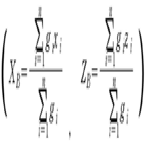
The coordinates (X B , Z B ) of the center-of-gravity point B of the

(The virtual fulcrum N is the same as the fulcrum of the outrigger) which is a fulcrum of the outrigger existing on the line connecting the center of gravity of the pump truck T and the center of gravity of the boom B or the fulcrum of the outrigger A first value obtained by multiplying the weight (G T ) of the pump truck by the center of gravity (T) of the pump truck and the length (L 1 ) between the support points (N) and the weight of the boom G B ) is compared with a second value obtained by multiplying the center of gravity of the boom by the length (L 2 ) between the support points in the
Hereinafter, preferred embodiments of the present invention will be described in detail with reference to the accompanying drawings.
5 is a plan view showing the outrigger length and the angle sensor installed on the outrigger.
In Fig. 5,
In FIG. 5, the length sensors and the angle sensors are omitted in the
7 is a plan view for explaining the extended state of the outrigger.
The length and angle of the
In addition, in the form of a length and angle of the mast arm of the
This transformation of the
Of course, it is also possible to directly process the position of each point with the polar coordinates length and angle without this conversion.
The
That is, the outrigger (30a) is a support point (x 1, y 1), the outrigger (30b) is a support point (x 2, y 2), the outrigger (30c) is a support point (x 3, y 3), Outrigger (30d) is described as being located at the support point (x 4, y 4). The location of the
The stable working range of the
Also outrigger in Fig. 7 (30a) (30b) ( 30d) are of an extended state, (30c) is a shortened state, the coordinates of their support point is (x 1, y 1) ( x 2, y 2) (x 31 , y 31 ) (x 4 , y 4 ). Each of the
Outrigger of (30a) (30b) (30c ) (30d) the geometric center of the extended state both is the point (P), the weight center point of the pump truck (1) is a point (T 0), the working The center of gravity of the
The circles represented by 0 °, + 30 °, + 150 °, -150 °, -30 °, and the like show a stable state in which the
8 is a plan view for explaining a state in which one of the outriggers is being shortened while the boom is being moved.
Outrigger (30c) support point (x 3, y 3) the coordinates (x of the coordinates (x T0, y T0) is a center of gravity (T 1) of the center of gravity (T 0) of the pump truck (1) as the speed of the T1 , y T1 ).
When moved to the center of gravity (B 0), the center of gravity (B 1) of the boom (10) center of gravity (B) is moved to the coordinates (x B1, B1 z) in the coordinate (x B0, B0 z).
In this case, in the
The center of gravity B of the

9 is a schematic view for explaining the center of gravity of each of the mast arms of the boom and the center of gravity of the boom according to the present invention.
9,
And g 1 (x 1, z 1 ), g 2 (x 2, z 2), g 3 (x 3, z 3), g 4 (x 4, z 4), g 5 (x 5, z 5) Represents the weight and the center of gravity of each of the
The X-axis in these X-Z coordinates is shown in the X-Y plane for the sake of convenience, omitting the Y-axis. Therefore, the value on the X-axis has a value on the X-Y plane.
The Z axis represents the value of the vertical axis of the mast arms.
The coordinates of the center of gravity of each mast arm have the length and angle ( 1 , 2 , 3 , 4 , 5 ) of each mast arm, Converted into the value of the XZ coordinate measured by the installed angle sensor and converted from the position information of the center of gravity (x 0 , z 0 ) of the initial mast arms stored in advance in the
Therefore, the weight (G B ) and the center of gravity (X B , Z B ) of the boom (10)

If there are 5 mast arms, n = 5
The center of gravity B 0 of the
Here, the coordinates (x B1 , y B1 ) of the center-of-gravity point B 1 in Fig. 8 are calculated as the center-of-gravity points X B5 and Z B5 in the above expression.
In order to prevent the
Therefore, in order that the mast arms of the
If the first value is not larger than the second value, the
If the first value is greater than the second value, it is determined that the
Although the position of the virtual support point N 1 has been described above as being on the line connecting the fulcrum point x 1 and y 1 of the
8 shows that the range of semicircle indicated by -30 °, 0 °, + 30 °, + 150 °, -150 °, etc. in the
Hereinafter, a preferred control method of the boom control apparatus according to the present invention will be described in detail.
10 is a flowchart for explaining a boom control method of a
A
The length of each of the sensors of the outrigger length sensor (210) (SL 1) ( SL 2) (SL 3) (SL 4) and brother each angle sensor on the trigger angle sensor (220) (SA 1) ( SA 2 The position information of the supporting points of the
When the positional information of the support points of the
The comparing
The angle sensor SBA 1 (SBA 2 ) of each of the
When the positional information of each of the mast arms is obtained as the values (x, y) of the rectangular coordinates, the process of calculating the values of the polar coordinates (r,?) As the values (x, y) of the rectangular coordinates is omitted in step S30.
When the fulcrum of the
The
The
If the first value is not larger than the second value, it is determined that the movement of the
When the operator continues the movement operation of the boom 10 (step S80), the operation proceeds to step S30. When the operator does not continue the movement operation of the boom 10 (step S80) The control of FIG.
The determination result of step S60 is displayed on the
The boom control apparatus and the control method thereof according to the present invention can be effectively used in the fields of high-altitude vehicles, ladder trucks, and concrete pump trucks.
121, 123, 125, 127, 129: mast arm
131, 133, 135, 137, 139: Joint axis
210: Outrigger Length Sensor Unit 220: Outrigger Angle Sensor Unit
230: Mast arm angle sensor unit 240: Boom rotation sensor unit
310: operation unit 320:
330: storage unit 340: operation control unit
410: mast arm relief operation part 420: boom rotation operation part
430: display 800:
Claims (6)
Wherein the boom has n (n is a natural number) mast arms, each of the booms has a boom actuating part for lifting up and down the mast arms;
Outriggers for fixing the pump truck to the ground;
And a boom control device for controlling the pump truck so as to prevent the pump truck from overturning when the boom ascends and descends;
Wherein the boom control device controls the boom control device by means of a fulcrum point by a fulcrum point of the outrigger or a fulcrum point by the fulcrum points of the outrigger which are on a line connecting the center of gravity of the pump truck and the changing center of gravity of the boom, A boom control apparatus for a pump truck, which is controlled by comparing a weight (G T ) with a weight (G B ) of the boom,
Wherein the boom control device calculates a change in the center of gravity (X B , Z B ) of the boom by comparing the weight (G T ) of the pump truck with the weight (G B ) of the boom, (g i ) and center of gravity points (x i , z i ) (i is 1 to n)
Wherein a weight (G T ) of the pump truck is multiplied by a first value obtained by multiplying a center-of-gravity point of the pump truck by a length (L 1 )
Comparing a second value obtained by multiplying the weight (G B ) of the boom by the length (L 2 ) between the changing center of gravity of the boom and the support point, and determining whether the first value is within a range Only the boom operation unit is operated,
Of the mast arms each weight center point (x i, z i) is the weight center point (x 0, z 0) of the initial mast arm of a previously stored for calculating the center of gravity (X B, Z B) the changing of the boom Wherein the position information is obtained by changing the position information under the control of the boom operating section and from the position information sensed by the respective sensors provided on the mast arms.
The weight (G B ) of the boom

Wherein the center of gravity of the pump truck and the support point are determined by the positions of the fulcrum points of the outriggers.
A boom actuating part for lifting up and down the plurality of mast arms;
Outriggers for fixing the pump truck to the ground;
A boom control method of a pump truck for controlling the pump truck to prevent overturning by using the center of gravity of the pump truck and the center of gravity of the boom when the boom equipped with the plurality of mast arms is lifted up and down,
Determining a center of gravity of the boom to calculate a changing center of gravity (X B , Z B ) of the boom from the center-of-gravity points (x i , z i ) of each of the plurality of mast arms (i is 1 to n);
Determining an actual or virtual support point on a line connecting the center of gravity of the pump truck and the center of gravity of the boom;
Calculating a length between each of the center of gravity of the pump truck and the center of gravity of the boom about the support point;
And determining whether the boom operation unit is operated based on the weight of the pump truck, the weight of the boom, and the calculated value using the respective lengths.
Priority Applications (1)
| Application Number | Priority Date | Filing Date | Title |
|---|---|---|---|
| KR1020150082781A KR101653773B1 (en) | 2015-06-11 | 2015-06-11 | Control device of concrete pump truck and the control method therefor |
Applications Claiming Priority (1)
| Application Number | Priority Date | Filing Date | Title |
|---|---|---|---|
| KR1020150082781A KR101653773B1 (en) | 2015-06-11 | 2015-06-11 | Control device of concrete pump truck and the control method therefor |
Publications (1)
| Publication Number | Publication Date |
|---|---|
| KR101653773B1 true KR101653773B1 (en) | 2016-09-06 |
Family
ID=56946183
Family Applications (1)
| Application Number | Title | Priority Date | Filing Date |
|---|---|---|---|
| KR1020150082781A KR101653773B1 (en) | 2015-06-11 | 2015-06-11 | Control device of concrete pump truck and the control method therefor |
Country Status (1)
| Country | Link |
|---|---|
| KR (1) | KR101653773B1 (en) |
Cited By (1)
| Publication number | Priority date | Publication date | Assignee | Title |
|---|---|---|---|---|
| KR20210144092A (en) | 2020-05-21 | 2021-11-30 | 대흥중공업 주식회사 | Crane vehicle |
Citations (3)
| Publication number | Priority date | Publication date | Assignee | Title |
|---|---|---|---|---|
| JP2639119B2 (en) * | 1989-07-31 | 1997-08-06 | 株式会社島津製作所 | crane |
| KR101104968B1 (en) | 2009-07-31 | 2012-01-12 | 주식회사 에버다임 | Safety system for concrete pump truck |
| KR20120116409A (en) * | 2010-03-30 | 2012-10-22 | 사니 헤비 인더스트리 컴패니, 리미티드 | Engineering machine and stability control system and control method thereof |
-
2015
- 2015-06-11 KR KR1020150082781A patent/KR101653773B1/en active IP Right Grant
Patent Citations (3)
| Publication number | Priority date | Publication date | Assignee | Title |
|---|---|---|---|---|
| JP2639119B2 (en) * | 1989-07-31 | 1997-08-06 | 株式会社島津製作所 | crane |
| KR101104968B1 (en) | 2009-07-31 | 2012-01-12 | 주식회사 에버다임 | Safety system for concrete pump truck |
| KR20120116409A (en) * | 2010-03-30 | 2012-10-22 | 사니 헤비 인더스트리 컴패니, 리미티드 | Engineering machine and stability control system and control method thereof |
Cited By (1)
| Publication number | Priority date | Publication date | Assignee | Title |
|---|---|---|---|---|
| KR20210144092A (en) | 2020-05-21 | 2021-11-30 | 대흥중공업 주식회사 | Crane vehicle |
Similar Documents
| Publication | Publication Date | Title |
|---|---|---|
| US10752479B2 (en) | System for stabilizing self-propelled operating machines | |
| JP6177400B1 (en) | Crane truck | |
| WO2014043997A1 (en) | Concrete pump truck monitoring method, concrete pump truck monitoring system, and concrete pump truck | |
| KR20120116409A (en) | Engineering machine and stability control system and control method thereof | |
| CN111017731A (en) | Machine, controller and control method | |
| EP3650396A1 (en) | Levelling system for a vehicle, and a method in relation to the system | |
| WO2019021123A1 (en) | A levelling system for work machines | |
| CN111721561B (en) | Method and device for judging stability of rotation operation and engineering machinery | |
| CN106585579A (en) | Leveling control method and leveling control system of firefighting vehicle | |
| KR101653773B1 (en) | Control device of concrete pump truck and the control method therefor | |
| US11713222B2 (en) | System and method for monitoring crane and crane having same | |
| JP7327052B2 (en) | HORIZONTAL POSITION DETERMINATION DEVICE FOR VEHICLE HAVING OUTRIGGER | |
| KR101653772B1 (en) | Control device of concrete pump truck | |
| KR101038523B1 (en) | Working radius of crane vehicle control device | |
| KR102153583B1 (en) | Display device of level adjusting of outrigger and the method there of | |
| CN113460912B (en) | Simulator for telescopic arm forklift | |
| JP3787058B2 (en) | Boom work vehicle body tilt angle detection device | |
| CN111017740B (en) | Crane, tower arm control method and tower arm control device | |
| KR101384512B1 (en) | Line-speed control method and apparatus for aerial work platform | |
| JP2001151491A (en) | Jack device for working vehicle | |
| JP4528688B2 (en) | Work vehicle | |
| JP6131097B2 (en) | Stroke end detection device for hoisting cylinder | |
| EP3694804A1 (en) | A predictive stability control method and system for truck-mounted cranes | |
| JP2003226492A (en) | Horizontally controlling device of workbench in vehicle for work at height | |
| JP2018104103A (en) | Inclination prevention apparatus for mobile crane |
Legal Events
| Date | Code | Title | Description |
|---|---|---|---|
| GRNT | Written decision to grant | ||
| FPAY | Annual fee payment |
Payment date: 20191023 Year of fee payment: 4 |