KR101613829B1 - Method and Apparatus for 3D Shape Measuring By Using Derivative Moire - Google Patents
Method and Apparatus for 3D Shape Measuring By Using Derivative Moire Download PDFInfo
- Publication number
- KR101613829B1 KR101613829B1 KR1020140055083A KR20140055083A KR101613829B1 KR 101613829 B1 KR101613829 B1 KR 101613829B1 KR 1020140055083 A KR1020140055083 A KR 1020140055083A KR 20140055083 A KR20140055083 A KR 20140055083A KR 101613829 B1 KR101613829 B1 KR 101613829B1
- Authority
- KR
- South Korea
- Prior art keywords
- moire
- absolute
- phase
- degree
- unit
- Prior art date
Links
Images

Classifications
-
- G—PHYSICS
- G01—MEASURING; TESTING
- G01B—MEASURING LENGTH, THICKNESS OR SIMILAR LINEAR DIMENSIONS; MEASURING ANGLES; MEASURING AREAS; MEASURING IRREGULARITIES OF SURFACES OR CONTOURS
- G01B11/00—Measuring arrangements characterised by the use of optical techniques
- G01B11/24—Measuring arrangements characterised by the use of optical techniques for measuring contours or curvatures
- G01B11/25—Measuring arrangements characterised by the use of optical techniques for measuring contours or curvatures by projecting a pattern, e.g. one or more lines, moiré fringes on the object
- G01B11/254—Projection of a pattern, viewing through a pattern, e.g. moiré
-
- G—PHYSICS
- G06—COMPUTING; CALCULATING OR COUNTING
- G06T—IMAGE DATA PROCESSING OR GENERATION, IN GENERAL
- G06T7/00—Image analysis
-
- G—PHYSICS
- G06—COMPUTING; CALCULATING OR COUNTING
- G06V—IMAGE OR VIDEO RECOGNITION OR UNDERSTANDING
- G06V10/00—Arrangements for image or video recognition or understanding
- G06V10/10—Image acquisition
- G06V10/12—Details of acquisition arrangements; Constructional details thereof
- G06V10/14—Optical characteristics of the device performing the acquisition or on the illumination arrangements
- G06V10/145—Illumination specially adapted for pattern recognition, e.g. using gratings
-
- G—PHYSICS
- G06—COMPUTING; CALCULATING OR COUNTING
- G06V—IMAGE OR VIDEO RECOGNITION OR UNDERSTANDING
- G06V20/00—Scenes; Scene-specific elements
- G06V20/60—Type of objects
- G06V20/64—Three-dimensional objects
Landscapes
- Engineering & Computer Science (AREA)
- Physics & Mathematics (AREA)
- General Physics & Mathematics (AREA)
- Computer Vision & Pattern Recognition (AREA)
- Theoretical Computer Science (AREA)
- Multimedia (AREA)
- Artificial Intelligence (AREA)
- Length Measuring Devices By Optical Means (AREA)
Abstract
미분 모아레를 이용한 3차원 형상 측정방법 및 장치를 개시한다.
본 실시예의 일 측면에 의하면, 모아레 간섭법을 이용한 3차원 형상 측정장치에 있어서, 인접한 두 측정점의 위상차를 이용하여 절대 모아레 차수의 상대적인 보정수치를 얻는 단위 보정부; 목표점에 이르기까지 상기 보정수치를 이용하여 절대 모아레 차수를 보정해 나가는 통합 보정부 및 상기 절대 모아레 차수를 이용하여 상기 목표점의 위상을 보정하는 위상 보정부를 포함하는 것을 특징으로 하는 모아레 간섭법을 이용한 3차원 형상 측정장치를 제공한다.A three-dimensional shape measuring method and apparatus using differential Moiré are disclosed.
According to an aspect of the present embodiment, there is provided a three-dimensional shape measuring apparatus using a moire interference method, comprising: a unit corrector for obtaining a relative correction value of an absolute moire degree by using a phase difference between two adjacent measurement points; And a phase correcting unit for correcting the phase of the target point by using the absolute moire degree, and a phase correcting unit for correcting the phase of the target point by using the absolute moire degree, Dimensional shape measuring apparatus.

Description
본 실시예는 미분 모아레(Derivative Moire)를 이용한 3차원 형상 측정방법 및 장치에 관한 것으로서, 보다 상세하게는 모아레 간섭법의 2π모호성(2π ambiguity)을 극복하도록 개선된 측정방법 및 장치에 관한 것이다.The present invention relates to a method and an apparatus for measuring a three-dimensional shape using a differential moire, and more particularly to an improved measuring method and apparatus for overcoming 2π ambiguity in a moire interference method.
이 부분에 기술된 내용은 단순히 본 실시예에 대한 배경정보를 제공할 뿐 종래기술을 구성하는 것은 아니다.The contents described in this section merely provide background information on the present embodiment and do not constitute the prior art.
3차원 형상 측정법은 최근 들어 많은 주목을 받고 있는 기술분야이다. 의료, 제조, 생체측정 등 공업적 적용범위의 확대로 인해 3차원 형상 측정 기술은 눈부시게 발전하고 있다. The 3D shape measurement method is a technology field that has received much attention in recent years. The three-dimensional shape measurement technology is remarkably developed due to the expansion of the industrial application range such as medical, manufacturing, and biometrics.
대표적인 3차원 형상 측정법으로는 레이저 스캐닝(Laser Scanning), 타임오브플라이트(TOF; Time of Flight), 스테레오 비전(Stereo Vision), 모아레 간섭법(Moire Interference) 등이 있다.Representative three-dimensional shape measurement methods include laser scanning, time of flight (TOF), stereo vision, moire interference, and the like.
레이저 스캐닝(Laser Scanning)은 물체 위에 레이저를 방사(emit)한 후 측면에서 보이는 레이저의 형태 변화를 관찰하여 물체의 3차원 정보를 취득하는 방법이다. 정밀한 3차원 정보를 취득할 수 있으나, 레이저 또는 물체를 움직여야 하므로 측정 속도가 느리다.Laser scanning is a method of acquiring three-dimensional information of an object by emulating a laser on the object and observing the shape change of the laser seen from the side. Precise three-dimensional information can be obtained, but the measurement speed is slow because a laser or an object must be moved.
타임오브플라이트(Time of Flight)는 물체 위에 Pulsed Light 또는 RF Modulated Light를 방사(emit)한 후 방사(emit)한 빛과 반사(reflected)된 빛을 비교하여 물체의 3차원 정보를 취득하는 방법이다. Pulsed Light 기법은 방사체로부터 방사된 빛이 물체 위에서 반사되어 돌아올 때까지의 시간을 측정하여 거리를 계산하는 방법이고, RF Modulated Light 기법은 물체 위에서 반사되어 돌아온 빛의 위상 변화(phase shift)를 측정하여 거리를 계산하는 방법이다. 측정속도가 빠르나, 빛이 방사체와 물체 사이를 오가는 도중에 왜곡되거나 산란되므로 정밀도가 떨어진다.Time of Flight is a method of acquiring three-dimensional information of an object by emulating Pulsed Light or RF Modulated Light on an object, then comparing the emitted light with the reflected light . The Pulsed Light technique is a method of calculating the distance by measuring the time from when the light emitted from the emitter is reflected on the object to returning. The RF Modulated Light technique measures the phase shift of the light reflected from the object It is a way to calculate the distance. Although the measurement speed is fast, the light is distorted or scattered while moving between the emitter and the object, and the accuracy is lowered.
스테레오 비전(Stereo Vision)은 인간이 두 눈을 이용하여 물체의 입체감을 느끼는 원리를 응용한 것으로서, 두 대의 카메라를 이용하여 동일한 대상을 촬영한 후, 두 영상을 비교하여 물체의 3차원 정보를 취득하는 방법이다. 비교적 저렴하고 간단한 방법으로 물체의 3차원 정보를 취득할 수 있으나, 원거리에 있는 물체를 측정하기 어렵고 두 영상 사이의 정합점(matching point)을 찾는 알고리즘이 복잡하다.Stereo Vision is the application of the principle that a human being feels stereoscopic effect of an object by using two eyes. It shoots the same object using two cameras and then compares two images and obtains three-dimensional information of the object . Although it is possible to acquire three-dimensional information of an object by a relatively inexpensive and simple method, it is difficult to measure an object at a distance and an algorithm for finding a matching point between two images is complicated.
그 때문에 현재 가장 주목받고 있는 3차원 형상 측정법은 모아레 간섭법(Moire Interference)이다. 모아레 간섭법은 물체 위에 일정한 간격(Grid)을 지닌 격자(grating)를 영사했을 때 물체 위에서 변형된 무늬(deformed grating)와 기준 무늬(reference grating)가 겹쳐졌을 때 발생하는 모아레(moire)를 관찰하여 물체의 3차원 정보를 취득하는 방법이다.Therefore, the three-dimensional shape measurement method which is currently attracting attention is Moire Interference. Moire interferometry is a method of observing the moire that occurs when a grating with a constant spacing (Grid) over an object overlaps a deformed grating and a reference grating on an object Dimensional information of an object.
모아레 간섭법을 이용하면 다른 측정법들에 비해 빠르고 효율적인 3차원 형상 측정이 가능하다. 그럼에도 불구하고 실제 산업현장에서 모아레 간섭법의 적용이 부진한 것은 모아레 간섭법이 지니는 두 가지 한계 때문이다. Using Moire interferometry, it is possible to perform 3D shape measurement faster and more efficiently than other measurement methods. Nevertheless, the lack of application of moire interferometry in real industry is due to two limitations of moire interferometry.
첫번째 한계는 모아레 간섭법으로 취득한 위상이 잡음(noise)으로 인해 분명하지 않은 것이고, 두번째 한계는 위상 펼치기(phase unwrapping)를 하는 과정에서 2π모호성이라고 불리는 측정오차가 발생하여 신뢰도가 떨어지는 것이다.The first limitation is that the phase acquired by the moire interferometry is not clear due to noise, and the second limit is the reliability of the phase unwrapping due to a measurement error called 2? Ambiguity.
첫번째 한계에 대해서는 코사인 트랜스폼(Cosine Transform), 웨이블렛 트랜스폼(Wavelet Transform) 등을 이용하여 잡음을 제거할 수 있다. 그러나 두번째 한계에 대해서는 명확한 해결 방법이 없다. 최소자승법(Least Square Method) 등을 이용하여 2π모호성의 문제를 해결하는 방법이 제안된 바 있지만, 최소자승법은 계산이 복잡할 뿐만 아니라 급작스러운 위상 변화를 제대로 반영하지 못하는 문제가 있다.For the first limit, noise can be removed using a cosine transform, a wavelet transform, or the like. However, there is no clear solution to the second limitation. Although a method of solving the problem of 2? Ambiguity has been proposed by using a Least Square Method, the least squares method has a problem in that calculation is complicated and the sudden phase change is not properly reflected.
본 실시예는 모아레 간섭법을 이용한 3차원 형상 측정방법 및 장치에 있어서, 기존 방법보다 빠르고 정확하게 2π모호성의 문제를 해결할 수 있도록 개선된 3차원 형상 측정방법 및 장치를 제공함에 그 목적이 있다.An object of the present invention is to provide a method and apparatus for measuring a three-dimensional shape using Moire interferometry, which can solve a problem of 2? Ambiguity more quickly and accurately than a conventional method.
본 실시예의 일 측면에 의하면, 모아레 간섭법을 이용한 3차원 형상 측정장치에 있어서, 인접한(adjacent) 두 측정점(measuring point)의 위상차를 이용하여 절대 모아레 차수(absolute moire order)의 상대적인(relative) 보정수치(adjust value)를 얻는 단위(unit) 보정부(adjust unit); 목표점(target point)에 이르기까지 상기 보정수치를 이용하여 절대 모아레 차수를 보정해 나가는 통합(integrated) 보정부(adjust unit) 및 상기 절대 모아레 차수를 이용하여 상기 목표점의 위상을 보정하는 위상(phase) 보정부(adjust unit)를 포함하는 것을 특징으로 하는 모아레 간섭법을 이용한 3차원 형상 측정장치(3D Shape Measuring Apparatus)를 제공한다.According to an aspect of the present embodiment, in a three-dimensional shape measuring apparatus using a moire interference method, relative phase correction of an absolute moire order is performed using a phase difference between two adjacent measuring points, An adjust unit for obtaining an adjust value; An integrated correction unit for correcting an absolute moire degree using the correction value to a target point and a phase adjusting unit for correcting the phase of the target point using the absolute moire degree, The present invention provides a 3D Shape Measuring Apparatus using a moire interference method, which includes an adjust unit.
본 실시예의 다른 측면에 의하면, 모아레 간섭법을 이용한 3차원 형상 측정법에 있어서, 인접한(adjacent) 두 측정점의 위상차(phase difference)를 이용하여 절대 모아레 차수의 상대적인(relative) 보정수치(adjust value)를 얻는 단위 보정 과정; 목표점에 이르기까지 상기 보정수치를 이용하여 절대 모아레 차수를 보정해 나가는 통합 보정 과정 및 상기 절대 모아레 차수를 이용하여 상기 목표점의 위상을 보정하는 위상 보정 과정을 포함하는 것을 특징으로 하는 모아레 간섭법을 이용한 3차원 형상 측정법(3D Shape Measuring Method)을 제공한다.According to another aspect of the present invention, in a three-dimensional shape measuring method using a moire interference method, a relative correction value of an absolute moire degree is calculated by using a phase difference between two adjacent measurement points A unit calibration process to obtain; And a phase correction step of correcting the phase of the target point by using the absolute moire degree. The method of
본 실시예에 의하면, 모아레 간섭법을 이용한 3차원 형상 측정에 있어서 인접한 두 측정점 사이의 높이 변화가 급격하더라도 정확한 높이 측정이 가능해짐으로써, 모아레 간섭법을 이용한 3차원 형상 측정에 대한 신뢰감을 향상시킴과 동시에 산업 전반에 걸쳐 모아레 간섭법의 적용 영역을 확장시킬 수 있다.According to this embodiment, in the three-dimensional shape measurement using the moire interference method, accurate height measurement can be performed even if the height change between adjacent two measurement points is abrupt, thereby improving the reliability of the three-dimensional shape measurement using the moire interference method It is possible to extend the application range of the moire interference method throughout the industry.
도 1은 모아레 무늬(moire pattern)를 도시한 도면이다.
도 2는 영사식 모아레 간섭법(Projection Moire Interference)의 측정원리를 도시한 도면이다.
도 3은 모아레 간섭법의 2π모호성(2π ambiguity)을 도시한 도면이다.
도 4는 위상천이식 모아레 간섭법(Phase Shifting Moire Interference)의 측정원리를 도시한 도면이다.
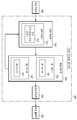
도 5는 미분 모아레(derivative moire)를 이용한 3차원 형상 측정장치의 블록도이다.
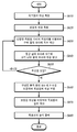
도 6은 미분 모아레(derivative moire)를 이용한 3차원 형상 측정방법의 흐름도이다.
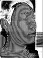
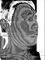
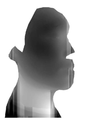
도 7은 본 실시예를 검증하기 위한 실험에서 측정대상이 된 사람의 얼굴이다.
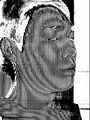
도 8 내지 11은 본 실시예를 검증하기 위한 실험에서 위상천이법(Phase Shifting Moire Interference)으로 취득한 변형된 격자(deformed grating)이다.
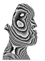
도 12는 본 실시예를 검증하기 위한 실험에서 위상천이법(Phase Shifting Moire Interference)으로 취득한 변형된 격자(deformed grating)를 기준 격자(reference grating) 위에 결상(imaging)시켰을 때 생기는 모아레 무늬이다.
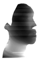
도 13은 본 실시예를 검증하기 위한 실험에서 위상천이법(Phase Shifting Moire Interference)으로 취득한 변형된 격자를 기준 격자 위에 결상(imaging)시켰을 때 생기는 모아레 무늬를 x축 방향으로 미분한 결과이다.
도 14는 본 실시예를 검증하기 위한 실험에서 위상천이법(Phase Shifting Moire Interference)으로 취득한 변형된 격자를 기준 격자 위에 결상시켰을 때 생기는 모아레 무늬를 y축 방향으로 미분한 결과이다.
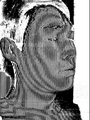
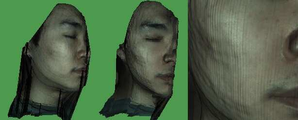
도 15는 본 실시예를 검증하기 위한 실험에서 미분 모아레(derivative moire)를 이용하여 계산한 절대 모아레 차수를 이용하여 얻은 최종적인 3차원 형상이다.FIG. 1 is a view showing a moire pattern. FIG.
FIG. 2 is a diagram showing a measurement principle of a projection moire interference method.
FIG. 3 is a diagram showing the 2? Ambiguity of the moire interference method. FIG.
4 is a diagram showing the principle of measurement of a phase shifting moire interference.
5 is a block diagram of a three-dimensional shape measuring apparatus using a derivative moire.
6 is a flowchart of a method of measuring a three-dimensional shape using a derivative moire.
7 is a face of a person to be measured in an experiment for verifying the present embodiment.
8 to 11 are deformed gratings obtained by phase shifting moire interference in an experiment for verifying the present embodiment.
12 is a moire pattern generated when a deformed grating obtained by a phase shifting moire interference is imaged on a reference grating in an experiment to verify the present embodiment.
FIG. 13 is a result of differentiating the moire pattern generated when the deformed grating acquired by the phase shifting Moire Interference is imaged on the reference grating in the x-axis direction in the experiment for verifying the present embodiment.
FIG. 14 is a result of differentiating the moire pattern generated when the deformed grating acquired by the Phase Shifting Moire Interference is imaged on the reference grating in the y-axis direction in the experiment for verifying the present embodiment.
FIG. 15 is a final three-dimensional shape obtained by using an absolute moire degree calculated using a derivative moire in an experiment for verifying the present embodiment.
이하 본 발명의 일부 실시예를 예시적인 도면을 통해 상세하게 설명한다. 각 도면의 구성요소들에 참조부호를 부가함에 있어서 동일한 구성요소들에 대해서는 비록 다른 도면상에 표시되더라도 가능한 한 동일한 부호를 가지도록 하고 있음에 유의해야 한다. 또한 본 실시예를 설명함에 있어서 관련된 공지 구성 또는 기능에 대한 구체적인 설명이 본 실시예의 요지를 흐릴 수 있다고 판단되는 경우에는 그 상세한 설명을 생략한다.Hereinafter, some embodiments of the present invention will be described in detail with reference to the accompanying drawings. It should be noted that, in the drawings, like reference numerals are used to denote like elements in the drawings, even if they are shown in different drawings. In the following description of the present invention, detailed description of known functions and configurations incorporated herein will be omitted when it may make the subject matter of the present disclosure rather unclear.
본 실시예의 구성요소를 설명하는 데 있어서 제1, 제2, ⅰ), ⅱ), a), b) 등의 부호를 사용할 수 있다. 이러한 부호는 그 구성요소를 다른 구성요소와 구별하기 위한 것일 뿐, 그 부호에 의해 해당 구성요소의 본질 또는 차례 또는 순서 등이 한정되지 않는다. 또한 명세서에서 어떤 부분이 어떤 구성요소를 '포함' 또는 '구비'한다고 할 때, 이는 명시적으로 반대되는 기재가 없는 한 다른 구성요소를 제외하는 것이 아니라 다른 구성요소를 더 포함할 수 있는 것을 의미한다. 또한 명세서에 기재된 '~부', '모듈' 등의 용어는 적어도 하나의 기능이나 동작을 처리하는 단위를 의미하며, 이는 '하드웨어' 또는 '소프트웨어' 또는 '하드웨어 및 소프트웨어의 결합'으로 구현될 수 있다.In describing the constituent elements of this embodiment, first, second, i), ii), a), b) and the like can be used. Such a code is intended to distinguish the constituent element from other constituent elements, and the nature of the constituent element, the order or the order of the constituent element is not limited by the code. It is also to be understood that when an element is referred to as being "comprising" or "comprising", it should be understood that it does not exclude other elements unless explicitly stated to the contrary, do. Also, the terms 'module', 'module' and the like described in the specification mean a unit for processing at least one function or operation, which can be implemented as 'hardware' or 'software' or 'combination of hardware and software' have.
본 실시예는 모아레 간섭법에서 필연적으로 발생하는 2π모호성을 극복하기 위한 측정방법 및 장치에 대한 것이다. This embodiment relates to a measurement method and apparatus for overcoming 2? Ambiguity necessarily occurring in the moire interference method.
2π모호성이란 모아레 무늬가 cos함수의 주기를 가지고 있음으로 인해 발생하는 문제로서, 2π모호성으로 인하여 모아레 무늬가 제공하는 정보만으로는 정확한 3차원 정보 취득이 불가능하다. 2π ambiguity is a problem caused by the fact that the moire pattern has a period of the cosine function. Due to the ambiguity of 2π, it is impossible to acquire accurate three-dimensional information by only information provided by the moire pattern.
지금까지 2π모호성을 극복하는 많은 방법들이 제시되어 왔으나, 2π모호성을 완벽하게 극복하기에는 부족한 점이 많거나 지나치게 복잡한 방법이었다. 본 실시예는 기존에 제시된 방법들과 달리, 모아레 무늬의 위상(phase of moire pattern)을 미분함으로써 간단하고 효율적으로 2π모호성의 문제를 해결하는 측정방법 및 장치를 제공한다.So far, many ways to overcome 2π ambiguity have been proposed, but it is either too much or too complicated to completely overcome 2π ambiguity. The present embodiment provides a measurement method and apparatus for solving the problem of 2? Ambiguity simply and efficiently by differentiating the phase of moire pattern unlike the existing methods.
본 실시예는 미분 연산을 이용하므로 본 실시예에 의한 측정방법 및 장치를 미분 모아레(Derivative Moire)를 이용한 측정방법 및 장치라고 한다.Since the present embodiment uses differential calculations, the measurement method and apparatus according to the present embodiment is referred to as a measurement method and apparatus using differential Moire.
본 실시예의 과제해결원리를 이해하기 위해서는 2π모호성에 대한 이해가 전제되어야 한다. ⅰ)모아레 간섭법(Moire Interference), ⅱ)영사식 모아레 간섭법(Projection Moire Interference), ⅲ)영사식 모아레 간섭법의 2π모호성, ⅳ)위상천이식 모아레 간섭법(Phase Shifting Moire Interference), ⅴ)위상천이식 모아레 간섭법의 2π모호성을 간단히 언급한 후, 미분 모아레에 대하여 상세히 설명한다.In order to understand the problem-solving principle of this embodiment, it is necessary to understand 2π ambiguity. I) Moire Interference, ii) Projection Moire Interference, iii) 2π ambiguity of projection moire interferometry, iv) Phase Shifting Moire Interference, v. ) Phase shifting After briefly mentioning the 2? Ambiguity of the moire interference method, the differential moire will be described in detail.
1. 모아레 간섭법1. moire interferometry
모아레 무늬(Moire Pattern)는 겹쳐진 비단이나 겹쳐진 모기장 등 일정한 간격을 갖는 무늬가 겹쳐졌을 때 생기는 무늬이다. 비슷한 주기를 갖는 여러 개의 무늬가 겹쳐졌을 때 맥놀이 현상(beating effect)에 의해 저주파에서 고유한 무늬가 생성되는데, 이를 모아레 무늬라고 한다.Moire Pattern is a pattern that occurs when overlapping patterns such as overlapping silk or overlapping mosquito nets overlap. When several patterns with similar cycles are overlapped, a beating effect generates a unique pattern at a low frequency, which is called a moire pattern.
모아레 무늬는 여러 가지 성질을 지니고 있다. 그 중 공학자들이 주목하는 것은 모아레 무늬가 물체의 움직임을 상당히 증폭해서 나타낼 수 있다는 점과 모아레 무늬가 물체의 형상에 대한 3차원 정보를 가지고 있다는 점이다. 이러한 성질을 이용하면 물체의 미세 거동 해석이나 물체의 3차원 형상 측정이 가능해진다.The moire pattern has various qualities. Among them, engineers note that the moire pattern can amplify the motion of the object considerably and that the moire pattern has three-dimensional information about the shape of the object. By using this property, it becomes possible to analyze the micro-behavior of the object or measure the three-dimensional shape of the object.
임의의 기준점에서 동시에 출발한 두 빛이 서로 다른 광경로(path of light)를 이동하면 간섭무늬(interference fringe)가 생겨난다. 이 때 생기는 간섭무늬는 광경로 차이에 의한 것이므로, 간섭무늬의 간격을 알면 역으로 광원에서 간섭무늬까지의 거리를 계산할 수 있다. 모아레 무늬도 간섭무늬의 일종으로서 이와 비슷한 방법으로 광원에서 물체의 표면까지의 높이를 구할 수 있다.An interference fringe is generated when two light sources that start at the same reference point travel in different paths of light. Since the interference pattern generated at this time is due to the difference in light path, if the interval of the interference fringes is known, the distance from the light source to the interference fringe can be calculated inversely. A moire pattern is also a kind of interference pattern, and the height from the light source to the surface of the object can be obtained in a similar way.
모아레 무늬는 모아레 간섭법에 의해 취득된다. 모아레 간섭법은 크게 그림자식 모아레 간섭법(shadow moire interference)과 영사식 모아레 간섭법(projection moire interference)으로 나뉜다.The moire pattern is acquired by the moire interference method. The moire interference method is divided into a shadow moire interference method and a projection moire interference method.
2. 영사식 모아레 간섭법2. Projection moire interference method
영사식 모아레 간섭법은 측정대상 위에 격자 무늬를 영사시킨 후, 측정대상 위에서 변형된 격자와 기준 격자가 겹쳐졌을 때 생기는 모아레 무늬를 관찰하는 방법이다. 영사식 모아레 간섭법을 이용하면 원거리에서 커다란 물체를 측정할 수 있다. 따라서 모아레 간섭법 중 일반적으로 이용되는 방법은 영사식이며, 본 실시예 또한 영사식 모아레 간섭법을 이용하고 있다.The projected moire interferometry is a method of observing a moire pattern generated when a grating pattern is projected on an object to be measured and then a deformed grating and a reference grating are overlapped on the object to be measured. Projection moire interferometry allows measurement of large objects over long distances. Therefore, the method generally used in the moire interference method is a projection type, and this embodiment also uses a projection moire interference method.
영사식 모아레 간섭법으로 물체의 3차원 형상을 측정하기 위해서는 먼저 기준 격자를 물체 위에 영사(projection)시켜야 한다. 영사된 격자는 물체의 형상에 따라 변형되는데, 변형된 격자(deformed grating)를 기준 격자(reference grating)위에 결상시키면 모아레 무늬가 나타난다. 이 때 생기는 모아레 무늬는 마치 등고선처럼 나타나기 때문에 이를 이용하여 물체의 편평도를 파악할 수 있다.In order to measure the three-dimensional shape of an object by projection-type moire interferometry, the reference grating must first be projected onto the object. The projected grating is deformed according to the shape of the object. When a deformed grating is imaged on a reference grating, a moire pattern appears. The Moire pattern that appears at this time looks like a contour line, so you can use it to grasp the flatness of an object.
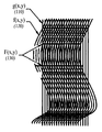
도 1은 모아레 무늬를 도시한 도면이다. 1 is a view showing a moire pattern.
도 1에서 물체 위에 세로로 반듯한 모양의 기준 격자(110)을 영사시키면 물체의 표면에서 물체의 굴곡에 따라 격자가 변형된다(120). 변형된 격자(120)를 기준 격자(110) 위에 결상시키면 결상 전에는 존재하지 않았던 가로 줄무늬가 생기는데, 이것이 모아레 무늬(130)이다. In FIG. 1, when a reference grating 110 having a vertical shape is projected on an object, the grating is deformed according to the bending of the object at the surface of the object (120). If the deformed grating 120 is imaged on the reference grating 110, there is a horizontal stripe that did not exist before the image formation, which is the
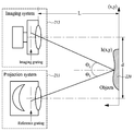
도 2는 영사식 모아레 간섭법의 측정원리를 도시한 도면이다.2 is a diagram showing the measurement principle of the projection type moire interference method.
영사시스템(projection system)(211)에서 물체(220)의 표면을 향해 기준 격자(Reference Grating)를 영사(projection)시킨다. 기준 격자는 물체(220)의 표면 위에서 변형되고, 변형된 격자(imaging grating)는 결상시스템(imaging system)(213)에서 기준 격자(reference grating) 위에 결상(imaging)되어 모아레 무늬를 형성한다.And projects a reference grating toward the surface of the
3. 영사식 모아레 간섭법의 2π모호성3. 2π ambiguity of projection-type moire interferometry
배율(magnification)이 M인 영사시스템(projection system)으로 피치(pitch)가 G인 격자(grating)를 영사(projection)했을 때, 물체의 표면의 측정점 x에 있는 변형된 격자는 수학식 1과 같은 광강도를 지닌다.When a grating with a pitch G is projected by a projection system with a magnification of M, the deformed grating at the measurement point x of the surface of the object can be expressed as in

수학식 1에서 I1(x, y)는 변형된 격자의 광강도(intensity of light), Isource는 광원의 세기(intensity of light source), R은 물체의 표면의 반사도, A는 격자의 모듈레이션(modulation), r(x, y)는 측정점(measuring point)의 거리, h(x, y)는 측정점의 높이, θ1은 측정점에 대한 영사시스템의 각도, M은 영사시스템의 배율, G는 격자(grating)의 피치(pitch)를 나타낸다.In
변형된 격자는 물체의 표면에서 반사된 후 결상시스템의 기준 격자 위에 결상되어 모아레 무늬를 형성한다. 이 때, 간단한 해석을 위하여 결상시스템에서 물체의 표면으로 기준 격자가 영사된다고 가정할 수 있다. 이 경우 기준 격자는 물체의 표면에서 수학식 2와 같은 광강도를 지닌다.The deformed grating is reflected on the surface of the object and is then imaged on the reference grating of the imaging system to form a moire pattern. At this time, it can be assumed that the reference grating is projected from the imaging system to the surface of the object for simple analysis. In this case, the reference grating has the light intensity as shown in Equation 2 on the surface of the object.

수학식 2에서 I2(x, y)는 기준 격자의 광강도, A는 격자의 모듈레이션, r(x, y)는 측정점의 거리, h(x, y)는 측정점의 높이, θ2는 측정점에 대한 결상시스템의 각도, M은 영사시스템의 배율, G는 격자의 피치를 나타낸다.In Equation 2 I 2 (x, y) is the light intensity of the reference grating, A is the modulation of the grating, r (x, y) is the distance of the measurement point, h (x, y) is height of measurement point, θ 2 is the measurement point M represents the magnification of the projection system, and G represents the pitch of the grating.
변형된 격자(deformed grating)가 기준 격자(reference grating) 위에 결상(imaging)되어 만들어지는 상은 수학식 3과 같은 광강도를 지닌다. An image formed by imaging a deformed grating on a reference grating has a light intensity as shown in Equation (3).

수학식 3에서 I(x, y)는 결상된 상의 광강도, I1(x, y)는 변형된 격자의 광강도, I2(x, y)는 기준 격자의 광강도를 나타낸다.In Equation 3, I (x, y) represents the light intensity of the image on the image, I 1 (x, y) represents the light intensity of the modified grating, and I 2 (x, y) represents the light intensity of the reference grating.
수학식 3을 전개하면 수학식 4가 도출된다.Expansion of equation (3) leads to equation (4).

수학식 4에서 I(x, y)는 결상된 상의 광강도, Isource는 광원의 세기, R은 물체의 표면의 반사도, A는 격자의 모듈레이션, r(x, y)는 측정점의 거리, h(x, y)는 측정점의 높이, θ1은 측정점에 대한 영사시스템의 각도, θ2는 측정점에 대한 결상시스템의 각도, M은 영사시스템의 배율, G는 격자의 피치를 나타낸다.In the equation (4), I (x, y) is the intensity of the image on the image, I source is the intensity of the light source , R is the reflectivity of the surface of the object, A is the modulation of the grating, r (x, y) is the height of the measuring point, θ 1 is the angle of the projection system relative to the measuring point, θ 2 is the angle of the imaging system with respect to the measuring point, M is the magnification of the projection system and G is the pitch of the grating.
또한 수학식 4에서 첫번째 항은 전체 영상의 배경영상, 두번째 항은 변형된 격자의 영상, 세번째 항은 기준 격자의 영상, 네번째 항은 두 격자의 간섭에 의한 영상을 각각 나타낸다.In Equation (4), the first term represents the background image of the entire image, the second term represents the image of the modified grating, the third term represents the image of the reference grating, and the fourth term represents the interference image of the two gratings.
네번째 항을 전개한 후 전개된 수학식에서 모아레 무늬에 해당하는 항만 따로 정리하면 수학식 5와 같다. Expression 5 is the sum of the term corresponding to the moire pattern in the expanded mathematical expression after developing the fourth term.

수학식 5에서 Imoire(x, y)는 결상된 상의 광강도, Isource는 광원의 세기, R은 물체의 표면의 반사도, A는 격자의 모듈레이션, h(x, y)는 측정점의 높이, θ1은 측정점에 대한 영사시스템의 각도, θ2는 측정점에 대한 결상시스템의 각도, M은 영사시스템의 배율, G는 격자의 피치를 나타낸다.I moire (x, y) is the light intensity on the image formation, I source is the intensity of the light source, R is the surface of the object reflectivity, A is the modulation of the grating, h (x, y) is the height of the measurement point in the equation (5), θ 1 is the angle of the projection system relative to the measuring point, θ 2 is the angle of the imaging system with respect to the measuring point, M is the magnification of the projection system, and G is the pitch of the grating.
수학식 5에서 알 수 있듯이, 모아레 무늬는 cos함수에 의한 주기를 가진다. 이 때 모아레 무늬의 위상 Φ는 수학식 6과 같다.As can be seen from Equation (5), the moire pattern has a period by the cosine function. At this time, the phase Φ of the moire pattern is expressed by Equation (6).

수학식 6에서 Φ(x, y)는 측정점에 생긴 모아레 무늬의 위상, h(x, y)는 측정점의 높이, θ1은 측정점에 대한 영사시스템의 각도, θ2는 측정점에 대한 결상시스템의 각도, M은 영사시스템의 배율, G는 격자의 피치를 나타낸다.H (x, y) is the height of the measurement point,? 1 is the angle of the projection system relative to the measurement point,? 2 is the phase of the imaging system for the measurement point Angle, M is the magnification of the projection system, and G is the pitch of the grating.
영사시스템에서 물체의 표면까지의 수평거리에 대하여 삼각함수를 적용하면 수학식 7이 성립한다. Applying a trigonometric function to the horizontal distance from the projection system to the surface of the object, Equation (7) holds.

수학식 7에서 θ1은 측정점에 대한 영사시스템의 각도, θ2는 측정점에 대한 결상시스템의 각도, d는 영사시스템과 결상시스템 사이의 간격, L은 영사시스템에서 기준면까지의 거리, h(x, y)는 측정점의 높이를 나타낸다.In equation (7), θ 1 is the angle of the projection system with respect to the measuring point, θ 2 is the angle of the imaging system with respect to the measuring point, d is the distance between the projection system and the imaging system, L is the distance from the projection system to the reference plane, h , y) represents the height of the measurement point.
수학식 6과 수학식 7을 연립하면 수학식 8이 도출된다.When Equation (6) and Equation (7) are combined, Equation (8) is derived.

수학식 8에서 Φ(x, y)는 측정점에 생긴 모아레 무늬의 위상(phase of moire pattern), d는 영사시스템과 결상시스템 사이의 간격, M은 영사시스템의 배율, G는 격자의 피치, L은 영사시스템에서 기준면(baseline)까지의 거리, h(x, y)는 측정점의 높이를 나타낸다.(X, y) is the phase of the moire pattern at the measurement point, d is the spacing between the projection system and the imaging system, M is the magnification of the projection system, G is the pitch of the grating, L Is the distance from the projection system to the baseline, and h (x, y) is the height of the measurement point.
모아레 무늬는 cos함수로 나타나므로 모아레 무늬의 위상은 2π를 주기로 반복된다. 따라서 수학식 8은 정확하게는 수학식 9과 같이 표현되어야 한다.Since the moire pattern is represented by the cosine function, the phase of the moire pattern is repeated with a period of 2π. Hence, Equation (8) should be exactly expressed as Equation (9).

수학식 9에서 Φ0은 모아레 무늬의 현재 위상, n은 절대 모아레 차수(absolute moire order), d는 영사시스템과 결상시스템 사이의 간격, M은 영사시스템의 배율, G는 격자의 피치, L은 영사시스템에서 기준면까지의 거리, h(x, y)는 측정점의 높이를 나타낸다.In equation (9), Φ 0 is the current phase of the moire pattern, n is the absolute moire order, d is the spacing between the projection system and the imaging system, M is the magnification of the projection system, G is the pitch of the grating, The distance from the projection system to the reference plane, h (x, y), represents the height of the measurement point.
절대 모아레 차수 n은 모아레 무늬의 현재 위상 Φ0이 몇 번의 2π의 주기를 거쳤는지에 대한 정보이다. 모아레 무늬의 현재 위상 Φ0을 아는 것만으로는 정확한 높이 측정이 불가능하므로, 측정점의 절대 모아레 차수 n을 알아야 한다.The absolute moire degree n is information on how many 2π cycles the current phase? 0 of the moire pattern has undergone. Knowing the current phase Φ 0 of the moire pattern does not allow accurate height measurement, so you need to know the absolute moire degree n of the measurement point.
측정점의 절대 모아레 차수 n을 알 수 없는 경우에는 인접한 두 측정점 사이의 위상차를 이용하여 상대적인 방법으로 위상을 계산한다.If the absolute moire degree n of the measurement point is not known, the phase is calculated in a relative manner using the phase difference between two adjacent measurement points.
두 측정점 사이가 아주 가깝다면 두 측정점 사이의 위상차가 2π보다 작을 것이라고 추정할 수 있다. 인접한 두 측정점 사이의 위상차가 2π보다 작다면 위상을 알고 있는 측정점에 인접한 측정점과의 위상차를 더함으로써 인접한 측정점의 위상을 계산할 수 있다. 이러한 방법으로 측정점의 위상을 계산하는 것을 위상 펼치기(phase unwrapping)이라고 한다.If the two measurement points are very close, it can be assumed that the phase difference between the two measurement points is less than 2 ?. If the phase difference between two adjacent measurement points is smaller than 2π, the phases of adjacent measurement points can be calculated by adding the phase difference from the measurement point adjacent to the measurement point whose phase is known. Calculating the phase of a measurement point in this way is called phase unwrapping.
그러나 위상펼치기는 인접한 두 측정점 사이의 위상 변화가 2π보다 작다는 가정을 전제로 한 것이므로, 인접한 두 측정점 사이의 위상 변화가 2π를 넘어서면 측정오류가 발생한다. 이것을 2π모호성이라고 한다.However, since the phase expansion is based on the assumption that the phase change between two adjacent measurement points is smaller than 2π, a measurement error occurs when the phase change between two adjacent measurement points exceeds 2π. This is called 2π ambiguity.
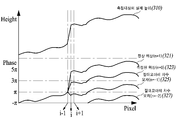
도 3은 모아레 간섭법의 2π모호성을 도시한 도면이다.3 is a diagram showing 2? Ambiguity in the moire interference method.
도 3을 보면 인접한 두 측정점 i-1과 i 사이에서 측정대상의 높이(310)가 급격하게 커진다. 그 결과 측정점 i-1과 i 사이의 모아레 무늬의 위상 변화가 2π를 초과한다. 모아레 무늬만으로는 2π를 초과하는 위상 변화를 파악할 수 없으므로, 모아레 무늬만으로 계산한 측정점의 높이(323)는 실제와 다르다.3, the height 310 of the measurement object suddenly increases between two adjacent measurement points i-1 and i. As a result, the phase shift of the moire pattern between measurement points i-1 and i exceeds 2 ?. Since the phase change exceeding 2? Can not be grasped only by the moire pattern, the height (323) of the measuring point calculated by only the moire pattern is different from the actual one.
이 경우 절대 모아레 차수 n을 이용하여 측정점 i의 위상을 보정해줘야 한다. 도 4에서 측정점 i의 위상을 보정하기 위한 절대 모아레 차수는 n=1이다. 따라서 n=1을 적용하면 올바른 위상(correct phase)(321)을 얻을 수 있다.In this case, the phase of the measurement point i must be corrected using the absolute moire degree n. In Fig. 4, the absolute moire degree for correcting the phase of the measurement point i is n = 1. Therefore, when n = 1 is applied, a correct phase 321 can be obtained.
절대 모아레 차수를 잘못 계산하면 잘못된 위상이 도출된다. 예컨대 n=-1을 적용하여 얻은 위상(325) 또는 n=-2를 적용하여 얻은 위상(327)은 측정대상의 실제 높이를 제대로 반영하지 못하고 있음을 알 수 있다.Incorrect calculation of the absolute moire order results in a false phase. For example, it can be seen that the phase 327 obtained by applying n = -1 or the phase 327 obtained by applying n = -2 does not properly reflect the actual height of the measurement object.
절대 모아레 차수 n을 알고 있다면 인접한 두 측정점 사이의 위상 변화가 2π를 초과하더라도 올바른 위상을 구할 수 있을 것이다. 그러나 절대 모아레 차수 n을 구하는 것은 쉽지 않은 문제로서 아직까지도 정확한 해법이 제시되지 않고 있다.If the absolute moire degree n is known, the correct phase will be obtained even if the phase change between two adjacent measurement points exceeds 2π. However, it is not easy to obtain the absolute moire degree n, and an accurate solution is not yet presented.
4. 위상천이식 모아레 간섭법4. Phase shifting moire interferometry
최근 들어 널리 활용되고 있는 위상천이식 모아레 간섭법(Phase Shifting Moire Interference)에서도 2π모호성이 문제된다. In the phase shifting moire interferometer, which is widely used in recent years, 2? Ambiguity is a problem.
일반적인 모아레 간섭법은 분해능이 낮아 정밀측정에 부적합하다. 이러한 모아레 간섭법의 분해능(resolution)을 높이기 위하여 개발된 기술이 위상천이식 모아레 간섭법이다. The general Moiré interference method is not suitable for precise measurement because of its low resolution. In order to increase the resolution of the Moire interferometry, a phase shifter moire interference technique is developed.
위상천이식 모아레 간섭법은 미세 구동기(Fine Actuator)를 장착하여 기준 미러(mirror)를 이동시키면서 여러 장의 간섭신호(interference signal)를 획득하고, 이로부터 영상 내의 각 측정점에서의 간섭신호의 형태와 높이와의 수학적 관계를 해석하는 방법이다. 위상천이식 모아레 간섭법은 분해능이 높고 모아레 무늬의 형태에 무관하게 3차원 형상 측정이 가능하다는 장점 때문에 광범위하게 이용되고 있다.The phase shifting moire interferometry is a method of acquiring a plurality of interference signals while moving a reference mirror with a fine actuator and obtaining the shape and the height of the interference signal at each measurement point in the image And is a way of interpreting the mathematical relationship with. Phase shifting moire interferometry is widely used because of its high resolution and its ability to measure three-dimensional shape irrespective of the shape of the moire pattern.
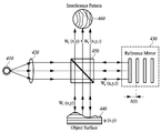
도 4는 위상천이식 모아레 간섭법의 측정원리를 도시한 도면이다.4 is a diagram showing the measurement principle of the phase-shifting moire interference method.
먼저 광원(410)에서 집광렌즈(condenser)(420)를 향해 빛(주로 백색광)을 방사한다. 집광렌즈를 통해 균일해진 빛은 분광기(spectrometer)(450)를 거쳐 기준 미러(reference mirror)(430)와 측정대상(440)의 표면에 도달한다. 기준 미러(430)에서 반사된 빛과 측정대상(440)의 표면에서 반사된 빛은 다시 분광기(450)를 거쳐 결상시스템에 도달한 후, 결상을 통해 모아레 무늬(460)를 형성한다.First, light (mainly white light) is emitted from the
위상천이식 모아레 간섭법에서 기준 미러(430)는 미세 구동기에 의해 이동하는데, 기준 미러(430)가 이동하면 광경로차(optical path difference)에 의해 위상차가 발생한다. 일반적으로 사용되는 4-버켓 알고리즘(4-Bucket Algorithm)에서는 위상차가 0˚, 90˚, 180˚, 270˚일 때의 광강도를 취득한 후, 그를 분석하여 측정대상의 3차원 정보를 취득한다.In the phase shifter moire interference method, the
5. 위상천이식 모아레 간섭법의 2π모호성5. 2π ambiguity of phase shifting moire interferometry
위상천이식 모아레 간섭법에서 측정점의 높이, 측정점의 위상, 영사하는 등가파장(equivalent wavelength)의 길이 사이의 관계는 수학식 10과 같다. In the phase shifting moire interferometry, the relationship between the height of the measurement point, the phase of the measurement point, and the length of the equivalent wavelength to be projected is shown in Equation (10).

수학식 10에서 h(x, y)는 측정점의 높이, λeq는 등가파장(equivalent wavelength)의 길이, Φ(x, y)는 측정점에 생긴 모아레 무늬의 위상을 나타낸다. In Equation (10), h (x, y) is the height of the measurement point, λ eq is the length of the equivalent wavelength, and Φ (x, y) indicates the phase of the moire pattern at the measurement point.
위상천이식 모아레 간섭법에서, 측정점 P(x, y)에 나타나는 모아레 무늬의 위상은 수학식 11과 같다.In the phase shifting moire interferometry, the phase of the moire pattern appearing at the measurement point P (x, y) is expressed by the following equation (11).

수학식 11에서 Φ0은 모아레 무늬의 현재 위상을 나타낸다. 그리고 위상천이식 모아레 간섭법에서 위상이동(phase shift)을 통해 두 격자 사이의 위상차(phase difference)가 순차적으로 0˚, 90˚, 180˚, 270˚가 될 때의 광강도를 각각 I1(x, y), I2(x, y), I3(x, y), I4(x, y)라고 한다.In Equation (11),? 0 represents the current phase of the moire pattern. In the phase-shifting moire interferometry, the light intensities when the phase differences between the two gratings are sequentially 0, 90, 180, and 270 degrees through phase shift are denoted by I 1 ( (x, y), I 2 (x, y), I 3 (x, y), and I 4 (x, y).
모아레 무늬는 cos함수로 나타나므로 모아레 무늬의 위상은 2π를 주기로 반복된다. 그러나 위상천이식 모아레 간섭법을 통해 취득하는 모아레 무늬의 위상(phase)은 아크탄젠트(arc-tangent)로 표현되고, 아크탄젠트는 -π/2에서 π/2까지의 값만을 가지므로, 위상천이식 모아레 간섭법에서 파악가능한 위상은 -π/2에서 π/2까지뿐이다. 따라서 위상천이식 모아레 간섭법을 이용하는 경우에는 인접한 두 측정점 사이의 기울기가 π를 넘으면 2π모호성의 문제가 발생한다. 구체적으로 수학식 10에 π를 대입하면 인접한 두 측정점의 높이차가 λeq/4를 넘으면 2π모호성의 문제가 발생함을 알 수 있다.Since the moire pattern is represented by the cosine function, the phase of the moire pattern is repeated with a period of 2π. However, since the phase of the moiré pattern obtained through the phase shifting moire interference method is represented by an arc tangent and the arc tangent has only a value from -π / 2 to π / 2, The phase that can be grasped by the transplant moiré interference method is only from -π / 2 to π / 2. Therefore, in the case of using the phase shifting moire interferometry, the problem of 2? Ambiguity occurs when the slope between adjacent two measurement points exceeds?. Specifically, if π is substituted in Equation 10, it can be seen that a problem of 2π ambiguity occurs when the height difference between two adjacent measurement points exceeds λ eq / 4.
수학식 10을 참조했을 때, 등가파장의 길이 λeq가 커지면, 측정가능한 두 인접점 사이의 높이차도 커진다. 즉, 등가파장의 길이 λeq를 늘림으로써 2π모호성을 방지할 수 있다. 그러나 등가파장의 길이 λeq가 커질수록 분해능이 낮아지기 때문에 실제로 잘 활용되는 방법은 아니다.Referring to Equation (10), when the length of the equivalent wavelength lambda eq is large, the height difference between two measurable adjacent points becomes large. That is, 2π ambiguity can be prevented by increasing the length λ eq of the equivalent wavelength. However, the larger the length of the equivalent wavelength λ eq , the lower the resolution.
수학식 11에 의할 때, 위상천이식 모아레 간섭법에서 구분가능한 위상은 -π/2에서 π/2까지의 π만큼의 범위이다. 따라서 위상천이식 모아레 간섭법에서 모아레 무늬의 위상은 정확하게는 수학식 12와 같이 표현되어야 한다.According to Equation (11), the phases that can be distinguished in the phase shifter moire interferometry range from -π / 2 to? / 2 by?. Therefore, in the phase shifting moire interference method, the phase of the moire pattern must be exactly expressed as: " (12) "

수학식 12에서 Φ(x, y)는 측정점에 생긴 모아레 무늬의 위상, Φ0은 모아레 무늬의 현재 위상, n은 절대 모아레 차수를 나타낸다.In Equation (12),? (X, y) represents the phase of the moire pattern at the measurement point,? 0 represents the current phase of the moire pattern, and n represents the absolute moire degree.
6. 미분 모아레 기법6. Differential moiré technique
본 실시예에서 제안하는 미분 모아레 기법은, 모아레 무늬의 위상을 미분함으로써 인접한 두 측정점 사이에서 절대 모아레 차수가 변하는 양상을 파악하고, 그를 통해 절대 모아레 차수를 구함으로써 2π모호성의 문제를 해결한다.The differential Moiré scheme proposed in this embodiment solves the problem of 2? Ambiguity by grasping the phase in which the absolute moire degree changes between two adjacent measurement points by differentiating the phase of the moire pattern and obtaining the absolute moire degree through it.
본 실시예는 미분을 이용하여 인접한 두 측정점 사이에서 절대 모아레 차수가 상승하는 경우와 하강하는 경우와 변하지 않는 경우를 구분함으로써 2π모호성의 문제를 해결한다. This embodiment solves the problem of 2? Ambiguity by distinguishing the case where the absolute moire degree rises between the two adjacent measurement points, the case where the absolute moire degree increases, and the case where it does not change.
구체적인 구분방법은 수학식 13과 같다.A specific method of classification is shown in Equation (13).

수학식 13에서 함수 u(t)는 t≥0일 때 u(t)=1이고, 그밖의 경우 u(t)=0인 함수이다. Φ0은 모아레 무늬의 현재 위상, Φd(Φdiscriminant)는 인접한 두 측정점 사이에서 절대 모아레 차수가 변하는 경우와 그렇지 않은 경우를 구분하기 위한 상수( constant number)를 나타낸다.The function u (t) in equation (13) is a function with u (t) = 1 when t? 0 and u (t) = 0 otherwise. Φ 0 is the current phase of the moiré pattern, and Φ d (Φ discriminant ) is a constant number to distinguish between cases where the absolute moire order varies between two adjacent measurement points.
수학식 13을 이용하면 현재 측정점에 대한 절대 모아레 차수의 보정수치를 얻을 수 있는데, 이를 단위(unit) 절대 모아레 차수라고 한다. 인접한 측정점들에 대하여 수학식 13을 연속하여 적용하면 x축에 대한 절대 모아레 차수를 계산할 수 있다.Using Equation (13), a correction value of the absolute moire degree for the current measurement point can be obtained, which is referred to as a unit absolute moire degree. The absolute moire degree for the x-axis can be calculated by applying Equation (13) successively to adjacent measurement points.
측정하고자 하는 목표점이 P(i, j)인 경우, y축 좌표를 j로 고정시킨 후 x축 좌표가 1일 때의 절대 모아레 차수의 변화량과 x축 좌표가 2일 때의 절대 모아레 차수의 변화량과 … x축 좌표가 i일 때의 절대 모아레 차수의 변화량을 계속 더해가면 목표점에서의 절대 모아레 차수의 보정값을 얻을 수 있는데, 이를 x축에 대한 통합(integrated) 절대 모아레 차수라고 한다. 이를 수학식으로 나타내면 수학식 14와 같다.When the target point to be measured is P (i, j), the variation of the absolute moire degree when the x-axis coordinate is 1 and the variation of the absolute moire degree when the x-axis coordinate is 2 after fixing the y- And ... If the variation of the absolute moire degree is continuously added when the x-axis coordinate is i, a correction value of the absolute moire degree at the target point can be obtained, which is referred to as an integrated absolute moire degree for the x-axis. This can be expressed by the following equation (14).

수학식 14에서 함수 u(t)는 t≥0일 때 u(t)=1이고, 그밖의 경우 u(t)=0인 함수이다. ni,j는 x축에 대한 통합 절대 모아레 차수, Φ0은 모아레 무늬의 현재 위상, Φd(Φdiscriminant)는 인접한 두 측정점 사이에서 절대 모아레 차수가 변하는 경우와 변하지 않는 경우를 구분하기 위한 상수를 나타낸다.The function u (t) in equation (14) is a function with u (t) = 1 when t? 0 and u (t) = 0 otherwise. Φ d (Φ discriminant ) is a constant for distinguishing between the case where the absolute moire degree is changed between the adjacent two measurement points and the case where the absolute moire degree is not changed between the adjacent two measurement points , n i, j is the integrated absolute moire degree for the x axis, Φ 0 is the current phase of the moire pattern, .
수학식 14에서 측정 방법 및 측정대상에 따라 Φd의 값은 달라질 수 있으며, 올바른 결과를 얻기 위한 Φd의 값은 실험적으로 결정된다. Φd의 값을 구하기 위한 실험은 본 발명이 속하는 기술분야에서 통상의 지식을 가진 자라면 용이하게 수행할 수 있는 것이다.In Equation (14), the value of? D may vary depending on the measurement method and the measurement object, and the value of? D for obtaining a correct result is determined experimentally. The experiment for obtaining the value of? D can be easily performed by a person having ordinary skill in the art to which the present invention belongs.
일반적으로 Φd는 0보다 크고 π보다 작은 값 중에서 π에 극히 가까운 값으로 선택된다. 예컨대 사람의 얼굴 및 석고상을 대상으로 한 실험에서는 Φd가 0.8π일 때 가장 정확한 결과가 도출되었다. In general, Φ d is selected to be extremely close to π among the values larger than 0 and smaller than π. For example, in experiments with human faces and plaster casts, the most accurate results were obtained when φ d was 0.8π.
수학식 14의 값은 수학식 15를 통해 계산할 수 있다.The value of Equation (14) can be calculated through Equation (15).

수학식 15에서 Φ0은 모아레 무늬의 현재 위상, I1(x, y), I2(x, y), I3(x, y), I4(x, y)는 위상천이식 모아레 간섭법에서 위상이동을 통해 두 격자 사이의 위상차가 순차적으로 0˚, 90˚, 180˚, 270˚가 될 때의 광강도를 나타낸다.Φ 0 is the current phase of the Moiré pattern in the equation 15, I 1 (x, y ), I 2 (x, y), I 3 (x, y), I 4 (x, y) is a phase shifter transplantation moire interference And the phase difference between the two gratings is sequentially 0, 90, 180, and 270 degrees.
x축에 대한 절대 모아레 차수를 이용하여 측정점 P(i, j)에서 x축 방향으로 위상 펼치기(phase unwrapping)를 해 준다(수학식 16 참조).the phase unwrapping is performed in the x-axis direction at the measurement point P (i, j) using the absolute moire degree for the x-axis (see Equation 16).

수학식 16에서 Φi,j x는 x축에 대한 위상 펼치기가 완료된 위상, Φ0은 모아레 무늬의 현재 위상, ni,j는 x축에 대한 통합 절대 모아레 차수를 나타낸다.In the equation (16), 陸i, j x represents a phase in which phase expansion is completed for the x axis, 陸0 represents a current phase of the moire pattern, and n i, j represents an integrated absolute moire degree for the x axis.
모아레 무늬를 미분하여 절대 모아레 차수를 구하고, 그를 통해 위상을 보정함에 있어서는, x축 방향뿐만 아니라 y축 방향도 고려해주어야 한다. 물체의 형태에 따라서는 가로축(x축)으로는 급격한 기울기의 변화가 없는 것이 세로축(y축)으로는 급격한 기울기의 변화가 일어나는 경우가 많기 때문이다. 예컨대 사람의 얼굴에서 코와 턱의 경우 가로축으로의 높이 변화는 적지만 세로축으로의 높이 변화는 크다. 이러한 경우 x축 방향으로만 위상 펼치기를 해주면 올바른 위상을 구할 수가 없으므로, y축 방향으로도 위상 펼치기를 해 주어야 한다.In order to obtain the absolute moire degree by differentiating the moire pattern and correct the phase through it, not only the x-axis direction but also the y-axis direction should be considered. This is because there is no abrupt gradient change along the horizontal axis (x axis) depending on the shape of the object, and a sudden gradient change occurs on the vertical axis (y axis) in many cases. For example, in the case of the nose and the jaw in the face of a person, the change in height to the horizontal axis is small, but the change in height to the vertical axis is large. In this case, if the phase expansion is performed only in the x-axis direction, the correct phase can not be obtained. Therefore, the phase expansion should also be performed in the y-axis direction.
y축에 대한 절대 모아레 차수는 다음과 같이 계산한다.The absolute moire degree for the y-axis is calculated as follows.
측정하고자 하는 목표점이 P(i, j)인 경우, x축 좌표를 i로 고정시킨 후 y축 좌표가 1일 때의 절대 모아레 차수의 변화량과 y축 좌표가 2일 때의 절대 모아레 차수의 변화량과 … y축 좌표가 j일 때의 절대 모아레 차수의 변화량을 계속 더해가면 목표점에서의 절대 모아레 차수의 보정값을 얻을 수 있는데, 이를 y축에 대한 통합 절대 모아레 차수라고 한다. 이를 수학식으로 나타내면 수학식 17과 같다.When the target point to be measured is P (i, j), the variation of the absolute moire degree when the y axis coordinate is 1 and the variation of the absolute moire degree when the y axis coordinate is 2 after fixing the x axis coordinate to i And ... If the variation of the absolute moire degree is continuously added when the y-axis coordinate is j, a correction value of the absolute moire degree at the target point can be obtained, which is referred to as an integrated absolute moire degree for the y-axis. This can be expressed by the following equation (17).

수학식 17에서 함수 u(t)는 t≥0일 때 u(t)=1이고, 그밖의 경우 u(t)=0인 함수이다. ni,j x는 y축에 대한 절대 모아레 차수, Φ0은 모아레 무늬의 현재 위상, Φd(Φdiscriminant)는 인접한 두 측정점 사이에서 절대 모아레 차수가 변하는 경우와 변하지 않는 경우를 구분하기 위한 상수를 나타낸다.In equation (17), the function u (t) is a function with u (t) = 1 when t? 0 and u (t) = 0 otherwise. Φ d (Φ discriminant ) is a constant for distinguishing between the case where the absolute moire degree changes between the adjacent two measurement points and the case where the absolute moire degree does not change between the adjacent two measurement points , n i, j x is the absolute moire degree for the y axis, Φ 0 is the current phase of the moire pattern, .
수학식 17의 값은 수학식 18을 통해 계산할 수 있다.The value of Equation (17) can be calculated through Equation (18).

수학식 18에서 Φ0은 모아레 무늬의 현재 위상, I1(x, y), I2(x, y), I3(x, y), I4(x, y)는 위상천이식 모아레 간섭법에서 위상이동을 통해 두 격자 사이의 위상차가 순차적으로 0˚, 90˚, 180˚, 270˚가 될 때의 광강도를 나타낸다.Φ 0 is the current phase of the Moiré pattern in the equation 18, I 1 (x, y ), I 2 (x, y), I 3 (x, y), I 4 (x, y) is a phase shifter transplantation moire interference And the phase difference between the two gratings is sequentially 0, 90, 180, and 270 degrees.
y축에 대한 절대 모아레 차수를 이용하여 측정점 P(i, j)에서 y축 방향으로 추가적인 위상 펼치기를 해 준다(수학식 19 참조).(see Equation 19) using the absolute moire degree for the y-axis at the measurement point P (i, j) in the y-axis direction.

수학식 19에서 Φi,j는 x축 및 y축에 대한 위상 펼치기가 완료된 위상, Φi,j x는 x축에 대한 위상 펼치기가 완료된 위상, ni,j x는 y축에 대한 절대 모아레 차수를 나타낸다.In the equation (19), 陸i, j is a phase in which phase expansion is completed with respect to the x and y axes, 陸i, j x is a phase in which phase expansion is completed with respect to the x axis, n i and j x are absolute moirés Represents the order.
이렇게 얻은 위상은 2π모호성의 문제가 없는 정확한 위상이므로, 이 위상을 이용하여 측정점의 정확한 높이를 구할 수 있다(수학식 10 참조).Since the obtained phase is an accurate phase without the problem of 2? Ambiguity, the accurate height of the measurement point can be obtained by using this phase (see Equation 10).
7. 미분 모아레 기법을 이용한 3차원 형상 측정장치7. 3D shape measuring device using differential Moiré technique
도 5는 미분 모아레를 이용한 3차원 형상 측정장치의 블록도이다.5 is a block diagram of a three-dimensional shape measuring apparatus using differential Moiré.
미분 모아레를 이용한 3차원 형상 측정장치는 모아레 측정장치의 위상 측정부(550)와 위상 출력부(570) 사이에 미분 모아레 연산부(500)를 추가함으로써 2π모호성의 문제를 해결한다. The three-dimensional shape measuring apparatus using differential Moiré solves the problem of 2? Ambiguity by adding the differential
미분 모아레 연산부(500)는 단위 보정부(510), 통합 보정부(520), 위상 보정부(530)를 포함한다.The differential
단위 보정부(510)는 단위 미분부(511)를 포함한다. 단위 미분부(511)은 모아레 무늬의 위상을 미분하는 기능을 수행한다. The
단위 미분부(511)는 단위 절대 모아레 차수 연산부(513)을 포함한다. 단위 절대 모아레 차수 연산부(513)는 수학식 13을 이용하여 절대 모아레 차수가 상대적으로 변하는 정도를 판단한다. The unit
통합 보정부(520)는 단위 절대 모아레 차수를 합산한다.The
통합 보정부(520)는 제1 보정부(521)를 포함한다. 제1 보정부(521)는 x축에 대한 단위 절대 모아레 차수를 합산한다. The
제1 보정부(521)는 제1 연산부(523)을 포함한다. 제1 연산부(523)는 수학식 14를 이용하여 x축에 대한 통합 절대 모아레 차수를 구한다.The
통합 보정부(520)는 또한 제2 보정부(521)를 포함한다. 제2 보정부(525)는 y축에 대한 단위 절대 모아레 차수를 합산한다. The
제2 보정부(525)는 제2 연산부(527)를 포함한다. 제2 연산부(527)는 수학식 17을 이용하여 y축에 대한 통합 절대 모아레 차수를 구한다.The
위상 보정부(530)는 최종적으로 구해진 통합 절대 모아레 차수를 이용하여 목표점의 위상을 보정하게 된다.The
이렇게 얻은 위상은 2π모호성의 문제가 없는 정확한 위상이므로, 이 위상을 이용하여 측정점의 정확한 높이를 구할 수 있다(수학식 10 참조).Since the obtained phase is an accurate phase without the problem of 2? Ambiguity, the accurate height of the measurement point can be obtained by using this phase (see Equation 10).
8. 미분 모아레 기법을 이용한 3차원 형상 측정방법8. 3D shape measurement method using differential Moiré technique
도 6은 미분 모아레를 이용한 3차원 형상 측정방법의 흐름도이다.6 is a flowchart of a method of measuring a three-dimensional shape using differential moire.
미분 모아레를 이용한 3차원 형상 측정방법은 목표점의 위상 측정 과정(S610)과 목표점의 높이 출력 과정(S680) 사이에 미분 모아레 연산 과정(S620~S670)을 추가함으로써 2π모호성의 문제를 해결한다. Dimensional shape measurement method using differential moiré solves the problem of 2? Ambiguity by adding the differential moiré calculation process (S620 to S670) between the phase measurement step S610 of the target point and the height output step S680 of the target point.
미분 모아레 연산을 위하여 원점(the starting point)의 위상을 측정한다(S620).The phase of the starting point is measured for the differential moiré calculation (S620).
원점에서 시작하여 인접한 측정점 사이의 단위 절대 모아레 차수를 구한다(S630). A unit absolute moire degree between the adjacent measurement points starting from the origin is obtained (S630).
목표점에 도달하기까지 인접한 측정점 사이의 단위 절대 모아레 차수를 합산함으로써 통합 절대 모아레 차수를 계산한다(S640). The integrated absolute moire degree is calculated by summing the unit absolute moire degree between adjacent measurement points until the target point is reached (S640).
목표점에 도달하면 합산을 중지하고(S650), 최종적으로 구해진 통합 절대 모아레 차수를 이용하여 목표점의 위상을 보정한다(S660).When the target point is reached, the summing is stopped (S650), and the phase of the target point is corrected using the finally obtained integrated absolute moire degree (S660).
이렇게 얻은 위상은 2π모호성의 문제가 없는 정확한 위상이므로, 이 위상을 이용하여 측정점의 정확한 높이를 구할 수 있다(수학식 10 참조).Since the obtained phase is an accurate phase without the problem of 2? Ambiguity, the accurate height of the measurement point can be obtained by using this phase (see Equation 10).
9. 미분 모아레 기법에 대한 검증9. Verification of differential Moiré technique
이하, 미분 모아레를 이용하여 2π모호성의 문제를 해결하는 것을 검증한 결과이다.Hereinafter, it is verified that the problem of 2? Ambiguity is solved by using differential Moiré.
도 7은 본 실시예를 검증하기 위한 실험에서 측정대상이 된 사람의 얼굴이다.7 is a face of a person to be measured in an experiment for verifying the present embodiment.
측정대상이 된 사람의 얼굴은 영사시스템에서 60cm 만큼 이격되었다. 영사시스템은 측정대상을 향하여 간격이 1mm이고 크기가 28cm x 35cm인 기준 격자를 영사하였다. The face of the person to be measured was separated by 60 cm from the projection system. The projection system projects a reference grating with a 1 mm gap and a size of 28 cm x 35 cm towards the object being measured.
도 8 내지 11은 본 실시예를 검증하기 위한 실험에서 위상천이법으로 취득한 변형된 격자이다. Figs. 8 to 11 are modified gratings acquired by the phase shift method in the experiment for verifying the present embodiment.
위상천이식 모아레 간섭법에서 위상이동(phase shift)을 통해 두 격자 사이의 위상차를 0˚, 90˚, 180˚, 270˚로 바꾸었을 때의 변형된 격자를 차례대로 도시하였다.In the phase shifting moire interferometry, the deformed lattices are shown in order when the phase difference between the two gratings is changed to 0 °, 90 °, 180 ° and 270 ° through phase shift.
도 12는 본 실시예를 검증하기 위한 실험에서 위상천이법으로 취득한 변형된 격자를 기준 격자 위에 결상시켰을 때 생긴 모아레 무늬이다. Fig. 12 is a moire pattern obtained when an image obtained by phase-shifting a deformed grating is imaged on a reference grating in an experiment to verify the present embodiment.
2π모호성 때문에 측정대상의 3차원 정보가 정상적으로 취득되지 못하였음을 알 수 있다.It can be seen that the 3-dimensional information of the measurement object can not be acquired normally due to the 2? Ambiguity.
도 13은 본 실시예를 검증하기 위한 실험에서 위상천이법으로 취득한 변형된 격자를 기준 격자 위에 결상시켰을 때 생기는 모아레 무늬를 x축 방향으로 미분한 결과이다.13 is a result of differentiating the moire pattern generated when the deformed grating acquired by the phase shift method is imaged on the reference grating in the x-axis direction in the experiment for verifying the present embodiment.
도 14는 본 실시예를 검증하기 위한 실험에서 위상천이법으로 취득한 변형된 격자를 기준 격자 위에 결상시켰을 때 생기는 모아레 무늬를 y축 방향으로 미분한 결과이다.14 is a result of differentiating the moire pattern generated when the deformed grating acquired by the phase shift method is imaged on the reference grating in the y axis direction in the experiment to verify the present embodiment.
도 15는 본 실시예를 검증하기 위한 실험에서 미분 모아레를 이용하여 계산한 절대 모아레 차수를 이용하여 얻은 최종적인 3차원 형상이다.15 is a final three-dimensional shape obtained by using the absolute moire degree calculated using the differential moiré in the experiment for verifying the present embodiment.
미분 모아레를 이용하면 2π모호성의 문제 없이 측정대상의 3차원 정보를 정확하게 취득할 수 있음을 알 수 있다.It can be seen that the use of the differential Moiré can accurately acquire the three-dimensional information of the measurement object without the problem of 2? Ambiguity.
본 실시예는 위상천이식 모아레 간섭법에 대해 미분 모아레를 적용하고 있으나, 본 발명이 속하는 기술분야에서 통상의 지식을 가진 자라면 위상천이식 모아레 간섭법 뿐만 아니라 영사식 모아레 간섭법, 그림자식 모아레 간섭법, 기타 다른 종류의 모아레 간섭법에 대해서도 본 실시예의 방법 또는 장치를 이용하여 2π모호성의 문제를 해결할 수 있을 것이다.The present embodiment applies differential phase moiré to the phase-shifting moire interferometry. However, those skilled in the art will appreciate that the phase-shifting moire interferometry as well as the projection moire interferometry, It is possible to solve the problem of 2? Ambiguity by using the method or apparatus of this embodiment also for the interference method and other kinds of moire interference methods.
본 실시예는 본 발명의 기술 사상을 예시적으로 설명한 것에 불과하고, 본 발명이 속하는 기술 분야에서 통상의 지식을 가진 자라면 본 발명의 본질적인 특성에서 벗어나지 않는 범위에서 본 실시예의 다양한 수정 및 변형이 가능할 것이다. 본 실시예는 본 발명의 기술 사상을 한정하기 위한 것이 아니라 설명하기 위한 것이고, 따라서 본 실시예에 의하여 본 발명의 권리범위가 한정되는 것은 아니다. 본 발명의 보호범위는 청구범위에 의하여 해석되어야 하며, 그와 동등하거나 균등하다고 인정되는 모든 기술 사상은 본 발명의 권리범위에 포함되는 것으로 해석되어야 한다.It will be apparent to those skilled in the art that various modifications and variations can be made in the present invention without departing from the spirit and scope of the invention as defined by the appended claims. It will be possible. The present invention is not intended to limit the scope of the present invention but to limit the scope of the present invention. The scope of protection of the present invention should be construed according to the claims, and all technical ideas considered to be equivalent or equivalent thereto should be construed as being included in the scope of the present invention.
110: 기준 격자 120: 변형된 격자
130: 모아레 무늬 211: 영사시스템
213: 결상시스템 220: 측정대상
310: 측정대상의 실제 높이 321: n=1일 때의 위상
323: n=0일 때의 위상 325: n=-1일 때의 위상
327: n=-2일 때의 위상 410: 광원
420: 집광렌즈 430: 기준 미러
440: 측정대상 450: 분광기
460: 모아레 무늬 500: 미분 모아레 연산부
510: 단위 보정부 511: 단위 미분부
513: 단위 절대 모아레 차수 연산부 520: 통합 보정부
521: 제1 보정부 523: 제1 연산부
525: 제2 보정부 527: 제2 연산부
530: 위상 보정부 550: 위상 측정부
570: 위상 출력부 110: reference grid 120: deformed grid
130: moire pattern 211: projection system
213: image forming system 220: measurement object
310: actual height of the measurement object 321: phase when n = 1
323: phase when n = 0 325: phase when n = -1
327: phase when n = -2 410: light source
420: condenser lens 430: reference mirror
440: object to be measured 450: spectroscope
460: moire pattern 500: differential moire calculator
510: unit correction unit 511: unit differential unit
513: unit absolute moire degree calculation unit 520:
521: first correction unit 523: first calculation unit
525: second correction unit 527: second operation unit
530: phase correction unit 550: phase measurement unit
570: phase output section
Claims (11)
인접한 두 측정점의 위상차를 이용하여 절대 모아레 차수의 상대적인 보정수치를 얻는 단위 보정부;
목표점에 이르기까지 상기 보정수치를 이용하여 절대 모아레 차수를 보정해 나가는 통합 보정부; 및
상기 절대 모아레 차수를 이용하여 상기 목표점의 위상을 보정하는 위상 보정부를 포함하되,
상기 단위 보정부는 상기 두 측정점 중 원점과 가까운 측의 측정점의 위상을 미분함으로써 상기 상대적인 보정 수치를 얻는 단위 미분부
를 포함하는 것을 특징으로 하는 모아레 간섭법을 이용한 3차원 형상 측정장치.A three-dimensional shape measuring apparatus using a moire interference method,
A unit corrector for obtaining a relative correction value of an absolute moire degree by using a phase difference between two adjacent measurement points;
An integral corrector for correcting an absolute moire degree by using the correction value to a target point; And
And a phase correcting unit for correcting the phase of the target point using the absolute moire degree,
Wherein the unit correction unit differentiates the phase of the measurement point on the side closer to the origin of the two measurement points to obtain the relative correction value,
Dimensional shape measuring device using a moire interference method.
상기 단위 미분부는,

(u(t)는 t≥0일 때 u(t)=1이고, 그밖의 경우 u(t)=0인 함수. Φ0은 모아레 무늬의 현재 위상. Φd(Φdiscriminant)는 인접한 두 측정점 사이에서 절대 모아레 차수가 변하는 경우와 그렇지 않은 경우를 구분하기 위한 상수)를 연산하는 단위 절대 모아레 차수 연산부
를 포함하는 것을 특징으로 하는 모아레 간섭법을 이용한 3차원 형상 측정장치.The method according to claim 1,
Wherein the unit differential section comprises:
(t) is a function with u (t) = 1 when t ≥ 0 and u (t) = 0 otherwise Φ 0 is the current phase of the moiré pattern Φ d (Φ discriminant ) A constant for dividing the case where the absolute moire degree varies between a case where the absolute moire degree is changed and a case where the absolute moire degree is not changed)
Dimensional shape measuring device using a moire interference method.
상기 통합 보정부는,
x축에 대한 절대 모아레 차수를 보정해 나가는 제1보정부; 및
y축에 대한 절대 모아레 차수를 보정해 나가는 제2보정부
를 포함하는 것을 특징으로 하는 모아레 간섭법을 이용한 3차원 형상 측정장치.The method according to claim 1,
The integrated correction unit may include:
a first correcting unit for correcting the absolute moire degree for the x axis; And
a second correction unit for correcting the absolute moire degree for the y-
Dimensional shape measuring device using a moire interference method.
상기 제1보정부는

(u(t)는 t≥0일 때 u(t)=1이고, 그밖의 경우 u(t)=0인 함수. ni,j는 x축에 대한 절대 모아레 차수. Φ0은 모아레 무늬의 현재 위상. Φd(Φdiscriminant)는 인접한 두 측정점 사이에서 절대 모아레 차수가 변하는 경우와 그렇지 않은 경우를 구분하기 위한 상수)를 연산하는 제1연산부를 포함하고,
상기 제2보정부는

(u(t)는 t≥0일 때 u(t)=1이고, 그밖의 경우 u(t)=0인 함수. ni,j x는 y축에 대한 절대 모아레 차수. Φ0은 모아레 무늬의 현재 위상. Φd(Φdiscriminant)는 인접한 두 측정점 사이에서 절대 모아레 차수가 변하는 경우와 그렇지 않은 경우를 구분하기 위한 상수)를 연산하는 제2연산부
를 포함하는 것을 특징으로 하는 모아레 간섭법을 이용한 3차원 형상 측정장치.5. The method of claim 4,
The first correction unit
(t) is a function with u (t) = 1 when t≥0 and otherwise u (t) = 0. n i, j is the absolute moiré order for the x axis, Φ 0 is the moiré pattern The present phase Φ d (Φ discriminant ) includes a first arithmetic unit for calculating a constant for distinguishing between the case where the absolute moire degree changes between the two adjacent measurement points and the case where the absolute moire degree is not changed,
The second correction unit
(t) is a function with u (t) = 1 when t ≥ 0 and otherwise u (t) = 0. n i, j x is the absolute moiré order for the y axis Φ 0 is the moiré pattern The second phase angle Φ d (Φ discriminant ) is a constant for distinguishing between the case where the absolute moire degree varies between two adjacent measurement points and the case where the absolute moire degree is not changed)
Dimensional shape measuring device using a moire interference method.
인접한 두 측정점 중 원점과 가까운 측의 측정점의 위상을 미분함으로써 절대 모아레 차수의 상대적인 보정수치를 얻는 단위 미분 과정;
목표점에 이르기까지 상기 보정수치를 이용하여 절대 모아레 차수를 보정해 나가는 통합 보정 과정; 및
상기 절대 모아레 차수를 이용하여 상기 목표점의 위상을 보정하는 위상 보정 과정
을 포함하는 것을 특징으로 하는 모아레 간섭법을 이용한 3차원 형상 측정법.In the three-dimensional shape measuring method using the moire interference method,
A unit derivative process of obtaining a relative correction value of an absolute moire degree by differentiating a phase of a measurement point near the origin among two adjacent measurement points;
An integrated correction process for correcting an absolute moire degree by using the correction value until reaching a target point; And
A phase correction process for correcting the phase of the target point using the absolute moire degree;
Dimensional shape measuring method using a moire interference method.
상기 단위 미분 과정은,

(u(t)는 t≥0일 때 u(t)=1이고, 그밖의 경우 u(t)=0인 함수. Φ0은 모아레 무늬의 현재 위상. Φd(Φdiscriminant)는 인접한 두 측정점 사이에서 절대 모아레 차수가 변하는 경우와 그렇지 않은 경우를 구분하기 위한 상수)을 연산하는 단위 절대 모아레 차수 연산 과정
을 포함하는 것을 특징으로 하는 모아레 간섭법을 이용한 3차원 형상 측정법.The method according to claim 6,
The unit differentiation process includes:
(t) is a function with u (t) = 1 when t ≥ 0 and u (t) = 0 otherwise Φ 0 is the current phase of the moiré pattern Φ d (Φ discriminant ) A constant for dividing the case where the absolute moire degree varies between the case where the absolute moire degree is changed and the case where the absolute moire degree is not changed)
Dimensional shape measuring method using a moire interference method.
상기 통합 보정 과정은,
x축에 대한 절대 모아레 차수를 보정해 나가는 제1 보정 과정; 및
y축에 대한 절대 모아레 차수를 보정해 나가는 제2 보정 과정
을 포함하는 것을 특징으로 하는 모아레 간섭법을 이용한 3차원 형상 측정법.The method according to claim 6,
The integrated correction process may include:
a first correction process for correcting the absolute moire degree for the x-axis; And
a second correction process for correcting the absolute moire degree for the y axis
Dimensional shape measuring method using a moire interference method.
x축에 대한 절대 모아레 차수를 보정해 나가는 제1 보정 과정은

(u(t)는 t≥0일 때 u(t)=1이고, 그밖의 경우 u(t)=0인 함수. ni,j는 x축에 대한 절대 모아레 차수. Φ0은 모아레 무늬의 현재 위상. Φd(Φdiscriminant)는 인접한 두 측정점 사이에서 절대 모아레 차수가 변하는 경우와 그렇지 않은 경우를 구분하기 위한 상수)을 연산하는 제1 연산 과정을 포함하고,
y축에 대한 절대 모아레 차수를 보정해 나가는 제2 보정 과정은

(u(t)는 t≥0일 때 u(t)=1이고, 그밖의 경우 u(t)=0인 함수. ni,j x는 y축에 대한 절대 모아레 차수. Φ0은 모아레 무늬의 현재 위상. Φd(Φdiscriminant)는 인접한 두 측정점 사이에서 절대 모아레 차수가 변하는 경우와 그렇지 않은 경우를 구분하기 위한 상수)을 연산하는 제2 연산 과정
을 포함하는 것을 특징으로 하는 모아레 간섭법을 이용한 3차원 형상 측정법.10. The method of claim 9,
The first correction process for correcting the absolute moire degree for the x-axis
(t) is a function with u (t) = 1 when t≥0 and otherwise u (t) = 0. n i, j is the absolute moiré order for the x axis, Φ 0 is the moiré pattern The current phase 陸d (陸discriminant ) includes a first calculation process for calculating a constant for distinguishing between the case where the absolute moire degree changes between the adjacent two measurement points and the case where the absolute moire degree is not changed,
The second correction process, which corrects the absolute moire degree for the y-axis,
(t) is a function with u (t) = 1 when t ≥ 0 and otherwise u (t) = 0. n i, j x is the absolute moiré order for the y axis Φ 0 is the moiré pattern The second phase of the second calculation process for calculating the phase difference Φ d (Φ discriminant ) is a constant for distinguishing between the case where the absolute moire degree changes between the two adjacent measurement points and the case where the absolute moire degree is not changed
Dimensional shape measuring method using a moire interference method.
Priority Applications (2)
| Application Number | Priority Date | Filing Date | Title |
|---|---|---|---|
| KR1020140055083A KR101613829B1 (en) | 2014-05-08 | 2014-05-08 | Method and Apparatus for 3D Shape Measuring By Using Derivative Moire |
| US14/299,079 US20150324657A1 (en) | 2014-05-08 | 2014-06-09 | Method and apparatus for measuring 3d shape by using derivative moire |
Applications Claiming Priority (1)
| Application Number | Priority Date | Filing Date | Title |
|---|---|---|---|
| KR1020140055083A KR101613829B1 (en) | 2014-05-08 | 2014-05-08 | Method and Apparatus for 3D Shape Measuring By Using Derivative Moire |
Publications (2)
| Publication Number | Publication Date |
|---|---|
| KR20150129184A KR20150129184A (en) | 2015-11-19 |
| KR101613829B1 true KR101613829B1 (en) | 2016-04-20 |
Family
ID=54368106
Family Applications (1)
| Application Number | Title | Priority Date | Filing Date |
|---|---|---|---|
| KR1020140055083A KR101613829B1 (en) | 2014-05-08 | 2014-05-08 | Method and Apparatus for 3D Shape Measuring By Using Derivative Moire |
Country Status (2)
| Country | Link |
|---|---|
| US (1) | US20150324657A1 (en) |
| KR (1) | KR101613829B1 (en) |
Families Citing this family (2)
| Publication number | Priority date | Publication date | Assignee | Title |
|---|---|---|---|---|
| US11982521B2 (en) * | 2017-02-23 | 2024-05-14 | Nikon Corporation | Measurement of a change in a geometrical characteristic and/or position of a workpiece |
| US11351810B2 (en) * | 2020-09-10 | 2022-06-07 | Ecole polytechnique fédérale de Lausanne (EPFL) | Synthesis of moving and beating moiré shapes |
Citations (4)
| Publication number | Priority date | Publication date | Assignee | Title |
|---|---|---|---|---|
| JP2006064590A (en) | 2004-08-27 | 2006-03-09 | Wakayama Univ | Line sensor, and shape measuring method and device by linear projector |
| JP2008241483A (en) | 2007-03-27 | 2008-10-09 | Matsushita Electric Works Ltd | Three-dimensional measurement method and three-dimensional shape measuring apparatus using the same |
| KR100893883B1 (en) | 2007-03-30 | 2009-04-20 | 주식회사 고영테크놀러지 | Apparatus and Method for Three Dimensional Measurement Using Moire and Dynamic Stereo Vision |
| KR101001894B1 (en) | 2008-10-13 | 2010-12-17 | 한국표준과학연구원 | Apparatus and method for 3-D profilometry using color projection moire technique |
Family Cites Families (4)
| Publication number | Priority date | Publication date | Assignee | Title |
|---|---|---|---|---|
| US5069548A (en) * | 1990-08-08 | 1991-12-03 | Industrial Technology Institute | Field shift moire system |
| DE60141848D1 (en) * | 2000-11-02 | 2010-05-27 | Zygo Corp | METHOD AND DEVICE FOR HEAVY-ABBEASTING INTERFEROMETRY WITH PHASE DIFFERENTIAL ANALYSIS |
| GB0119036D0 (en) * | 2001-08-06 | 2001-09-26 | South Bank Univ Entpr Ltd | Three dimensional imaging |
| US6842254B2 (en) * | 2002-10-16 | 2005-01-11 | Fiso Technologies Inc. | System and method for measuring an optical path difference in a sensing interferometer |
-
2014
- 2014-05-08 KR KR1020140055083A patent/KR101613829B1/en not_active IP Right Cessation
- 2014-06-09 US US14/299,079 patent/US20150324657A1/en not_active Abandoned
Patent Citations (4)
| Publication number | Priority date | Publication date | Assignee | Title |
|---|---|---|---|---|
| JP2006064590A (en) | 2004-08-27 | 2006-03-09 | Wakayama Univ | Line sensor, and shape measuring method and device by linear projector |
| JP2008241483A (en) | 2007-03-27 | 2008-10-09 | Matsushita Electric Works Ltd | Three-dimensional measurement method and three-dimensional shape measuring apparatus using the same |
| KR100893883B1 (en) | 2007-03-30 | 2009-04-20 | 주식회사 고영테크놀러지 | Apparatus and Method for Three Dimensional Measurement Using Moire and Dynamic Stereo Vision |
| KR101001894B1 (en) | 2008-10-13 | 2010-12-17 | 한국표준과학연구원 | Apparatus and method for 3-D profilometry using color projection moire technique |
Also Published As
| Publication number | Publication date |
|---|---|
| US20150324657A1 (en) | 2015-11-12 |
| KR20150129184A (en) | 2015-11-19 |
Similar Documents
| Publication | Publication Date | Title |
|---|---|---|
| KR100919166B1 (en) | Stereo Moire Measurement Apparatus and Method | |
| KR102149707B1 (en) | 3D shape measurement device, 3D shape measurement method and program | |
| Felipe-Sese et al. | Simultaneous in-and-out-of-plane displacement measurements using fringe projection and digital image correlation | |
| US20090097039A1 (en) | 3-Dimensional Shape Measuring Method and Device Thereof | |
| EP1643210A1 (en) | Method and apparatus for measuring shape of an object | |
| CN104215193B (en) | Object plane distortion measurement method and measuring system | |
| EP3631757B1 (en) | Deriving topology information of a scene | |
| WO1997036144A1 (en) | Method and apparatus for measuring shape of objects | |
| US9441959B2 (en) | Calibration method and shape measuring apparatus | |
| CN108332684A (en) | A kind of measuring three-dimensional profile method based on Structured Illumination microtechnic | |
| KR102218215B1 (en) | Mutual reflection detection device, mutual reflection detection method and program | |
| US9036157B2 (en) | System of computing surface reconstruction, in-plane and out-of-plane displacements and strain distribution | |
| KR101613829B1 (en) | Method and Apparatus for 3D Shape Measuring By Using Derivative Moire | |
| RU2616070C2 (en) | Method for determining position of, at least, one object edge by assessment of fresnel diffraction border profiles | |
| Rodríguez | Online self-calibration for mobile vision based on laser imaging and computer algorithms | |
| Boukamcha et al. | Robust technique for 3D shape reconstruction | |
| Lim et al. | A novel one-body dual laser profile based vibration compensation in 3D scanning | |
| Bräuer-Burchardt et al. | Phase unwrapping in fringe projection systems using epipolar geometry | |
| CN112212805B (en) | Efficient three-dimensional phase unwrapping method based on composite coding | |
| Poroykov et al. | Development of a Phasogrammetric Measurement System for Error Estimation in Close-Range Photogrammetry | |
| JP5359565B2 (en) | Waveform analysis apparatus, computer-executable waveform analysis program, interferometer apparatus, pattern projection shape measurement apparatus, and waveform analysis method | |
| KR100681885B1 (en) | Profilometry | |
| JP2013024737A (en) | Method and device for measuring three-dimensional shape, and microscope device for three-dimensional shape measurement | |
| KR20090091093A (en) | Stereo moire measurement apparatus and method | |
| Lee et al. | An active vision sensor system employing adaptive digital fringe pattern generated by SLM pattern projector |
Legal Events
| Date | Code | Title | Description |
|---|---|---|---|
| A201 | Request for examination | ||
| E902 | Notification of reason for refusal | ||
| E701 | Decision to grant or registration of patent right | ||
| GRNT | Written decision to grant | ||
| LAPS | Lapse due to unpaid annual fee |