KR101453327B1 - Fundus imaging method, fundus imaging apparatus, and storage medium - Google Patents
Fundus imaging method, fundus imaging apparatus, and storage medium Download PDFInfo
- Publication number
- KR101453327B1 KR101453327B1 KR1020110135165A KR20110135165A KR101453327B1 KR 101453327 B1 KR101453327 B1 KR 101453327B1 KR 1020110135165 A KR1020110135165 A KR 1020110135165A KR 20110135165 A KR20110135165 A KR 20110135165A KR 101453327 B1 KR101453327 B1 KR 101453327B1
- Authority
- KR
- South Korea
- Prior art keywords
- aberration
- unit
- function
- correction
- reference value
- Prior art date
Links
Images


Classifications
-
- A—HUMAN NECESSITIES
- A61—MEDICAL OR VETERINARY SCIENCE; HYGIENE
- A61B—DIAGNOSIS; SURGERY; IDENTIFICATION
- A61B3/00—Apparatus for testing the eyes; Instruments for examining the eyes
- A61B3/10—Objective types, i.e. instruments for examining the eyes independent of the patients' perceptions or reactions
- A61B3/12—Objective types, i.e. instruments for examining the eyes independent of the patients' perceptions or reactions for looking at the eye fundus, e.g. ophthalmoscopes
-
- A—HUMAN NECESSITIES
- A61—MEDICAL OR VETERINARY SCIENCE; HYGIENE
- A61B—DIAGNOSIS; SURGERY; IDENTIFICATION
- A61B3/00—Apparatus for testing the eyes; Instruments for examining the eyes
- A61B3/10—Objective types, i.e. instruments for examining the eyes independent of the patients' perceptions or reactions
- A61B3/14—Arrangements specially adapted for eye photography
-
- A—HUMAN NECESSITIES
- A61—MEDICAL OR VETERINARY SCIENCE; HYGIENE
- A61B—DIAGNOSIS; SURGERY; IDENTIFICATION
- A61B3/00—Apparatus for testing the eyes; Instruments for examining the eyes
- A61B3/10—Objective types, i.e. instruments for examining the eyes independent of the patients' perceptions or reactions
- A61B3/1015—Objective types, i.e. instruments for examining the eyes independent of the patients' perceptions or reactions for wavefront analysis
Abstract
안저 촬상장치는 피검사물에 측정광을 조사해서 얻은 반사광의 수차를 측정하는 수차측정유닛과, 상기 측정된 수차에 따라 빛의 수차를 보정하는 수차보정유닛과, 상기 수차측정유닛과 상기 수차보정유닛의 처리를 반복해서 제어하는 제어유닛과, 상기 수차측정유닛의 측정 결과 및 상기 제어유닛의 제어 결과 중 적어도 한 개에 따라, 상기 수차를 나타내는 소정의 차수의 제1의 함수를, 상기 소정의 차수보다도 높은 차수를 포함하는 제2의 함수로 변경하는 변경유닛을 구비한다. 상기 수차보정유닛은, 상기 제2의 함수로 나타낸 수차를 보정한다.The funduscopic imaging apparatus includes an aberration measurement unit that measures aberration of reflected light obtained by irradiating a measurement object with a measurement light, an aberration correction unit that corrects aberration of light according to the measured aberration, A first function of a predetermined degree representing the aberration in accordance with at least one of a measurement result of the aberration measurement unit and a control result of the control unit; To a second function including a higher degree than the first function. The aberration correction unit corrects the aberration represented by the second function.
Description
본 발명은, 안저 촬상방법, 안저 촬상장치, 및 기억매체에 관한 것이다.
The present invention relates to a funduscopic imaging method, a funduscopic imaging device, and a storage medium.
최근, 안과용의 촬상장치로서, 안저에 2차원적으로 레이저 빔을 조사하고, 그 반사광을 수광해서 화상화하는 SLO(Scanning Laser Ophthalmoscope)이 개발되어 있다. 또한, 안과용의 촬상장치로서, 저코히렌스광의 간섭을 이용한 이미징 장치가 개발되어 있다. 저코히렌스광의 간섭을 이용한 이미징 장치는, OCT(Optical Coherence Tomography)이라고 불리며, 특히, 안저 혹은 그 근방 영역의 단층 화상을 취득할 목적으로 이용되고 있다. TD-OCT(Time Domain OCT)와, SD-OCT(Spectral Domain OCT)을 포함하는 다양한 종류의 OCT가 개발되어 있다. 안과용의 촬상장치는, 최근에 있어서, 조사 레이저의 고 NA화 등에 의해 더욱 고해상도화가 진행되고 있다.2. Description of the Related Art In recent years, as an imaging apparatus for ophthalmology, an SLO (Scanning Laser Ophthalmoscope) has been developed in which a fundus is irradiated two-dimensionally with a laser beam and the reflected light is received and imaged. Further, as an imaging apparatus for ophthalmology, an imaging apparatus using interference of low coherence light has been developed. An imaging apparatus using interference of low coherence light is called OCT (Optical Coherence Tomography), and is used particularly for acquiring a tomographic image of the fundus or its vicinity. Various types of OCTs including TD-OCT (Time Domain OCT) and SD-OCT (Spectral Domain OCT) have been developed. [0003] In recent years, imaging apparatuses for ophthalmology have progressed to higher resolutions by increasing the NA of the irradiation laser.
그렇지만, 안저를 촬상할 경우에는, 각막과 수정체 등의 눈의 광학 조직을 통해서 촬상을 해야만 한다. 그 때문에 고해상도화가 진행함에 따라, 이들 각막과 수정체의 수차가 촬상 화상의 화질에 크게 영향을 주게 되었다.However, when imaging fundus images, it is necessary to perform imaging through the optical tissues of the eye such as the cornea and the lens. Therefore, as the resolution increases, the aberrations of the cornea and the lens greatly affect the image quality of the captured image.
그러한 사정 때문에, 눈의 수차를 측정하고, 그 수차를 보정하는 AO(Adaptive Optics) 기능을 광학계에 포함하고 있는 AO-SLO과 AO-OCT의 연구가 진행되고 있다. 예를 들면, 비특허문헌 1(Y. Zhang et al, Optics Express, Vol. 14, No. 10, 15 May 2006)에, AO-OCT의 예가 개시되어 있다. 이들 AO-SLO와 AO-OCT는, 샥-하트만(Shack-Hartmann) 파면 센서 방식에 의해 눈의 파면을 측정한다. 샥-하트만 파면 센서 방식은, 눈에 측정광을 인가해서 그 반사광을 마이크로렌즈 어레이를 통과시켜서 CCD 카메라가 수광함으로써 눈의 파면을 측정하도록 설계되어 있다. 측정한 파면을 보정하도록 가변형 미러와 공간 위상 변조기를 구동하여, 그들을 통해서 안저의 촬상을 행함으로써, AO-SLO나 AO-OCT는 고분해능 촬상이 가능해진다.Due to such circumstances, studies on AO-SLO and AO-OCT, which include an adaptive optics (AO) function for measuring aberrations of the eye and correcting the aberrations, are underway. For example, an example of AO-OCT is disclosed in Non-Patent Document 1 (Y. Zhang et al, Optics Express, Vol. 14, No. 10, May 15, 2006). These AO-SLO and AO-OCT measure the wavefront of the eye by the Shack-Hartmann wavefront sensor method. The 샥-Hartmann wavefront sensor system is designed to measure the wavefront of the eye by applying the measurement light to the eye and passing the reflected light through the microlens array and receiving it by the CCD camera. The variable mirror and the spatial phase modulator are driven to correct the measured wavefront, and imaging of the fundus is performed through them, so that AO-SLO or AO-OCT can perform high resolution imaging.
눈의 수차의 대부분은, 근시, 원시, 및 난시 등의 저차의 수차이다. 그렇지만, 수차는 또한 눈의 광학계의 미세한 요철과 누액층의 디스터번스(disturbance)에 기인하는, 보다 고차의 수차를 포함한다. 눈의 수차를 제르니케 함수계로 표현할 경우, 이 수차를 표현하는 제르니케 함수의 대부분은 근시, 원시, 및 난시를 표현하는 제르니케 2차 함수이다. 이들 함수는 제르니케 3차 함수와 제르니케 4차 함수를 약간 포함하고, 한층 더 제르니케 5차 함수와 제르니케 6차 함수 등의 보다 고차의 함수를 조금 포함한다.Most of the aberrations of the eye are aberration of lower order such as nearsightedness, primacy, and astigmatism. However, the aberration also includes a higher order aberration due to the microscopic unevenness of the optical system of the eye and the disturbance of the leakage layer. When the aberrations of the eye are expressed in the Zernike function system, most of the Zernike functions expressing this aberration are Zernike quadratic functions expressing myopic, primitive, and astigmatism. These functions include some Zernike cubic functions and Zernike quadratic functions, and even a few higher order functions such as the Zernike fifth order function and the Zernike sixth order function.
일반적으로, 안과장치에 사용하는 AO(Adaptive Optics)는, 파면 센서로 측정한 수차를 제르니케 함수와 같은 함수로 모델화하고, 그 함수를 사용해서 파면 보정기의 보정량을 계산한다. 함수로 수차를 모델화해서 정량적으로 취득한 양을, 수차량이라고 칭한다. 또한, 파면 보정기가 그 함수를 사용해서 수차를 보정하기 위한 파면 보정값을 보정량이라고 칭한다. 복잡한 형상을 보정하기 위해서는, 많은 차수를 갖는 함수로 수차를 모델화해서 보정량을 산출하고, 파면 보정기를 제어할 필요가 있다.Generally, Adaptive Optics (AO) used in ophthalmic devices models the aberration measured by a wavefront sensor with a function such as a Zernike function, and calculates the correction amount of the wavefront compensator using the function. The quantity quantitatively obtained by modeling the aberration as a function is referred to as an aberration amount. The wavefront correction value for correcting the aberration by using the function of the wavefront compensator is referred to as a correction amount. In order to correct a complicated shape, it is necessary to model the aberration by a function having many orders and to calculate a correction amount, and to control the wavefront compensator.
그렇지만, 많은 차수를 갖는 함수로 수차를 모델화해서 보정량을 산출하면, 계산 부하가 매우 커져서, 계산 시간이 증대해, 큰 문제가 되고 있다. 특히, 눈의 수차에 대해서는, 눈물의 상태와 시도(dioptic) 조절의 상태가 항상 변화되고, 단층 화상의 취득은 수차보정을 고속으로 반복할 필요가 있기 때문에, 처리 속도의 향상이 매우 중요하다.However, if the correction amount is calculated by modeling the aberration with a function having many orders, the calculation load becomes very large, and the calculation time increases, which is a big problem. Particularly, regarding the aberration of the eye, it is very important to improve the processing speed because the state of the tear and the state of the dioptic adjustment are always changed, and the acquisition of the tomographic image requires repetition of the aberration correction at high speed.
본 발명은, 상기의 문제를 감안하여 이루어진 것으로, 수차보정을 위한 연산 처리를 고속으로 행하는 것이 가능한 안저 촬상 기술을 제공한다.The present invention has been made in view of the above-described problems, and provides a funduscopic imaging technique capable of performing arithmetic processing for aberration correction at high speed.
본 발명의 일 국면에 의하면, 피검사물에 측정광을 조사해서 취득한 반사광의 수차를 측정하는 수차측정 유닛과, 상기 측정된 수차에 따라 빛의 수차를 보정하는 수차보정유닛과, 상기 수차측정유닛과 상기 수차보정유닛의 처리를 반복해서 제어하는 제어유닛을 포함하는 안저 촬상장치의 안저 촬상방법으로서, 상기 수차측정유닛에 의해 취득된 측정 결과와 상기 제어유닛에 의해 취득된 제어 결과 중 적어도 한 개에 따라, 수차를 나타내는 미리 정해진 차수를 포함하는 제1의 함수 및 상기 미리 정해진 차수보다 높은 차수를 포함하는 제2의 함수 중 하나를 선택하는 선택 단계와, 상기 선택 단계의 결과에 근거하여, 상기 제1의 함수 또는 상기 제2의 함수로 나타낸 수차를 보정하는 수차보정단계를 포함한다. According to an aspect of the present invention, there is provided an aberration measuring apparatus comprising: an aberration measuring unit for measuring aberration of reflected light acquired by irradiating a measurement object with an object to be measured; an aberration correcting unit correcting aberration of light according to the measured aberration; And a control unit for repeatedly controlling the process of the aberration correction unit, wherein the at least one of the measurement result obtained by the aberration measurement unit and the control result acquired by the control unit A selection step of selecting one of a first function including a predetermined order representing the aberration and a second function including an order higher than the predetermined order; and a selection step of selecting, based on the result of the selection step, 1 or an aberration correction step of correcting the aberration represented by the second function.
본 발명의 다른 국면에 의하면, 피검사물에 측정광을 조사해서 취득한 반사광의 수차를 측정하는 수차측정유닛과, 상기 측정된 수차에 따라 빛의 수차를 보정하는 수차보정유닛과, 상기 수차측정유닛과 상기 수차보정유닛의 처리를 반복해서 제어하는 제어유닛과, 상기 수차측정유닛에 의해 취득된 측정 결과와 상기 제어유닛에 의해 취득된 제어 결과 중 적어도 한 개에 따라, 상기 수차를 나타내는 미리 정해진 차수를 포함하는 제1의 함수 및 상기 미리 정해진 차수보다도 높은 차수를 포함하는 제2의 함수 중 하나를 선택하는 선택유닛을 구비하고, 상기 수차보정유닛은, 상기 선택 유닛에 의한 선택에 근거하여, 상기 제1의 함수 또는 상기 제2의 함수로 나타낸 수차를 보정한다.According to another aspect of the present invention, there is provided an aberration measuring apparatus comprising: an aberration measuring unit that measures aberration of reflected light acquired by irradiating a measurement object with an object to be measured; an aberration correction unit that corrects aberration of light according to the measured aberration; A control unit that repeatedly controls the processing of the aberration correction unit and a control unit that sets a predetermined order representing the aberration according to at least one of a measurement result obtained by the aberration measurement unit and a control result obtained by the control unit And a selection unit for selecting one of a first function including a first function and a second function including a degree higher than the predetermined order, wherein the aberration correction unit corrects, based on the selection by the selection unit, 1 or the aberration represented by the second function.
본 발명에 의하면, 수차 보정을 위한 연산 처리를 고속으로 행하는 것이 가능하게 된다.According to the present invention, it is possible to perform the arithmetic processing for aberration correction at high speed.
본 발명의 그외의 특징들은 첨부도면을 참조하면서 이하의 예시적인 실시예의 설명으로부터 밝혀질 것이다.Other features of the present invention will become apparent from the following description of exemplary embodiments with reference to the attached drawings.
도 1은 제1 실시예에 있어서의 보상 광학계를 구비한 SLO에 의한 안저 촬상장치의 구성 예를 도시한 도면이다.
도 2는 제1 실시예에 있어서의 파면 보정 디바이스의 일례를 나타내는 모식도이다.
도 3은 파면 보정 디바이스의 다른 구성 예를 도시한 도면이다.
도 4a 및 4b는 샥-하트만 파면 센서의 구성을 나타내는 모식도이다.
도 5는 파면을 측정하는 광선이 CCD 센서 위에 포커스된 상태를 나타내는 모식도이다.
도 6은 구면 수차를 갖는 파면을 측정했을 때의 모식도이다.
도 7은 제1 실시예에 있어서의 안저 촬상장치의 제어 스텝을 도시한 플로차트이다.
도 8은 제2 실시예에 있어서의 안저 촬상장치의 제어 스텝을 도시한 플로차트이다.
도 9는 제3 실시예에 있어서의 안저 촬상장치의 제어 스텝을 도시한 플로차트이다
도 10은 제4 실시예에 있어서의 보상 광학계를 구비한 SLO에 의거한 안저 촬상장치의 구성 예를 도시한 도면이다.
도 11은 제4 실시예에 있어서의 안저 촬상장치의 제어 스텝을 도시한 플로차트이다.Fig. 1 is a view showing an example of the configuration of a funduscopic imaging apparatus using SLO equipped with a compensation optical system according to the first embodiment. Fig.
2 is a schematic diagram showing an example of a wavefront compensation device according to the first embodiment.
3 is a diagram showing another example of the configuration of the wavefront compensation device.
4A and 4B are schematic diagrams showing the configuration of a 샥-Hartmann wavefront sensor.
5 is a schematic diagram showing a state in which a light beam for measuring a wavefront is focused on a CCD sensor.
Fig. 6 is a schematic diagram when a wave front having spherical aberration is measured.
Fig. 7 is a flowchart showing a control step of the funduscopic imaging apparatus according to the first embodiment. Fig.
8 is a flowchart showing the control step of the funduscopic imaging apparatus according to the second embodiment.
9 is a flow chart showing a control step of the funduscopic imaging apparatus according to the third embodiment
10 is a diagram showing a configuration example of a funduscopic imaging apparatus based on an SLO having a compensation optical system according to the fourth embodiment.
11 is a flowchart showing the control step of the funduscopic imaging apparatus according to the fourth embodiment.
이하, 도면을 참조하여, 본 발명의 바람직한 실시예를 예시적으로 자세하게 설명한다. 다만, 이 실시예에 기재되어 있는 구성요소는 어디까지나 예시이며, 본 발명의 기술적 범위는, 특허청구범위에 의해 확정되는 것이며, 이하의 개별의 실시예에 의해 한정되는 것은 아니다.Hereinafter, preferred embodiments of the present invention will be described in detail with reference to the drawings. However, the constituent elements described in this embodiment are merely examples, and the technical scope of the present invention is determined by the claims, and is not limited to the following specific embodiments.
(제1 실시예)(Embodiment 1)
본 발명의 제1 실시예에 따른 안저 촬상장치의 구성에 대해서 도 1을 참조하여 설명한다. 또한, 본 실시예에 있어서는, 측정 대상인 피검사물을 눈이라고 하고, 눈에서 발생하는 수차를 보상 광학계(adaptive optics system)로 보정하며, 안저를 촬상하는 경우를 예시할 것이다.A configuration of a funduscopic imaging apparatus according to a first embodiment of the present invention will be described with reference to Fig. In this embodiment, a case will be exemplified in which an object to be measured is an eye, an aberration generated in the eye is corrected by an adaptive optics system, and a fundus image is picked up.
도 1에 있어서, 이 장치는 광원(101)으로서 파장 840nm의 SLD(Super Luminescent Diode) 광원을 사용하고 있다. 광원(101)의 파장은 특히 제한되는 것은 아니고, 안저 촬상용으로서는 피검자의 눈부심의 경감과 분해능 유지를 위해서, 800nm∼1500nm정도의 파장을 사용한다. 본 실시예에 있어서는 SLD 광원을 사용했지만, 레이저 등을 사용하는 것이 가능하다. 본 실시예에서는 안저 촬상과 파면 측정을 위해 같은 광원을 이용하고 있지만, 서로 다른 광원을 사용해서 광로의 도중에서 빛을 멀티플레싱하는 구성을 형성하는 것이 가능하다.1, this apparatus uses an SLD (Super Luminescent Diode) light source having a wavelength of 840 nm as the
광원(101)으로부터 조사된 빛은, 단일 모드 광파이버(102)를 통과하고, 콜리메이터(103)를 통해서 평행 광선(측정광(105))으로서 조사된다. 조사된 측정광(105)은 빔 스플리터(beam splitter)로부터 형성된 광 분할부(104)를 투과하여, 보상 광학계로 도광된다. 보상 광학계는, 광 분할부(106), 파면 센서(115), 파면 보정 디바이스(108) 및 그들로 도광하기 위한 반사 미러 107-1∼107-4로 구성된다. 본 실시예는 광 분할부(106)로서 빔 스플리터를 사용하고 있다. 반사 미러 107-1∼107-4은, 적어도 눈(111)의 동공, 파면 센서(115), 및 파면 보정 디바이스(108)가 광학적으로 공역관계가 되도록 배치되어 있다.The light emitted from the
광 분할부(106)를 투과한 측정광(105)은, 반사 미러 107-1과 107-2에서 반사되어서 파면 보정 디바이스(108)에 입사한다. 파면 보정 디바이스(108)에서 반사된 측정광(105)은, 반사 미러 107-3에 출사된다. 본 실시예에서는, 파면 보정 디바이스(108)로서 액정소자를 사용한 공간 위상 변조기(반사형 액정 광 변조기)를 사용하고 있다. 도 2는 반사형 액정 광변조기의 모식도를 나타낸다. 반사형 액정 광변조기는 베이스부(122)와 커버(123)에 의해 정의된 공간에 액정분자가 밀봉되어 있는 구조를 갖는다. 베이스부(122)는 복수의 화소 전극(124)을 갖고, 커버(123)는 (도면에 나타내지 않은) 투명한 대향 전극을 갖는다. 전극 사이에 전압을 인가하지 않을 경우에는, 액정분자는 "125-1"과 같은 배향 상태를 한다. 전극 사이에 전압을 인가하면, 액정분자는 "125-2"과 같은 배향상태로 천이하고, 입사광에 대한 굴절율이 변화된다. 각각의 화소 전극(124)에의 전압을 제어해서 각 화소의 굴절율을 변화시킴으로써, 공간적인 위상 변조가 가능해진다. 예를 들면, 입사광(126)이 반사형 액정 광변조기에 입사했을 경우, 액정분자 125-2을 통과하는 빛은 액정분자 125-1을 통과하는 빛에 대한 위상 지연(phase lag)을 나타낸다. 결과적으로, 도 2 중의 파선 127로 나타낸 바와 같은 파면을 형성한다. 일반적으로, 반사형 액정 광변조기는, 몇만∼몇십만 개의 화소로 구성되어 있다. 또한, 반사형 액정 광변조기는 편광 특성을 갖도록 입사광의 편광을 조정하기 위한 편광소자를 구비할 수도 있다.The
파면 보정 디바이스(108)의 다른 예로서는, 가변형 미러가 이용가능하다. 가변형 미러는, 국소적으로 빛의 반사 방향을 바꿀 수 있다. 다양한 종류의 가변형 미러가 이용가능하다. 가변형 미러는, 예를 들면 도 3에 나타낸 단면을 갖는 디바이스로서 형성되고, 입사광을 반사하는 변형가능한 막의 형태의 미러면(129)과, 베이스부(128)와, 미러면(129)과 베이부(128) 사이에 삽입된 액추에이터(130)와, 미러면(129)을 그 주위에서 지지하는 (도면에 나타내지 않은) 지지부로 구성되어 있다. 액추에이터(130)의 동작 원리로서는, 정전력, 자기력, 혹은 압전 효과를 이용한 것이 있다. 동작 원리에 따라 액추에이터(130)의 구성이 다르다. 액추에이터(130)는 베이스부(128) 위에 이차원적으로, x-y평면 내에, 복수의 어레이로 배열되어 있다. 액추에이터(130)를 선택적으로 구동하는 것에 의해, 미러면(129)을 도 3 중의 z방향으로 자유롭게 변형할 수 있다. 일반적으로, 가변형 미러는 몇십∼몇백의 액추에이터로 구성되어 있다.As another example of the
도 1에 있어서, 반사 미러 107-3, 107-4로 반사된 빛은, 주사 광학계(109)에 의해, 1차원 혹은 2차원으로 주사된다. 본 실시예에서는, 주사 광학계(109)는 주주사 동작(안저의 수평방향)과 부주사 동작(안저의 수직방향)에 대해서 각각 사용된 2개의 갈바노미터(Galvanometer)를 포함하고 있다. 보다 빠른 촬상 동작을 위해서, 주사 광학계(109)의 주주사 동작에 대해서 공진 스캐너를 사용할 수도 있다. 주사 광학계(109) 내의 각 스캐너를 광학적으로 공역한 상태로 설정하기 위해서, 주사 광학계(109)는 각 스캐너 사이에 미러와 렌즈 등의 광학소자를 사용하는 구성을 가져도 된다.In Fig. 1, the light reflected by the reflection mirrors 107-3 and 107-4 is scanned one-dimensionally or two-dimensionally by the scanning
주사 광학계(109)에 의해 주사된 측정광(105)은, 접안 렌즈 110-1 및 110-2을 통과하여 눈(111)에 조사된다. 눈(111)에 조사된 측정광(105)은 안저에서 반사 혹은 산란된다. 접안 렌즈 110-1 및 110-2의 위치를 조정함으로써, 눈(111)의 시도에 맞춰서 최적의 조사를 행하는 것이 가능해진다. 이 경우, 접안부에 접안 렌즈를 사용했지만, 구면 미러 등을 사용하는 것도 가능하다.The
눈(111)의 망막으로부터 반사 혹은 산란된 광은, 입사광의 경로를 따라 반대로 진행한다. 광분할부(106)는 파면 센서(115)에 광의 일부를 반사하여, 광선의 파면을 측정하는 데에 사용한다.Light reflected or scattered from the retina of the
본 실시예에서는 파면 센서(115)로서 샥-하트만 파면 센서를 사용하고 있다. 도 4a 및 4b는 샥-하트만 파면 센서의 모식도를 나타낸다. 참조번호 131은 파면을 측정하는 광선이며, 마이크로렌즈 어레이(132)를 통과하여, CCD 센서(133) 상의 초점면(134)에 포커스된다. 도 4b는 도 4A의 A-A' 단면을 따라 취한 단면도이다. 마이크로렌즈 어레이(132)는, 복수의 마이크로렌즈(135)로 구성되어 있다. 광선(131)은 각각의 마이크로렌즈(135)를 통해서 CCD 센서(133) 상에 포커스된다. 그 결과, 광선(131)은 마이크로렌즈(135)의 개수에 해당하는 스폿으로 분할되어서 포커스된다. 도 5는 빛이 CCD 센서(133) 위에 포커스된 상태를 나타낸다. 각 마이크로렌즈를 통과한 광선은 스폿(136)에 포커스된다. 그리고, 파면 센서는 각각의 스폿(136)의 위치부터 입사한 광선의 파면을 계산한다. 예를 들면, 도 6은 구면 수차를 갖는 파면을 측정했을 경우의 모식도를 나타낸다. 광선(131)은 파선 137로 나타낸 것과 같은 파면으로 형성되어 있다. 광선(131)은 마이크로렌즈 어레이(132)에 의해, 파면에 국소적으로 수직인 방향의 위치에 포커스된다. 도 6은, 이 경우의 CCD 센서(133)의 포커스된 상태를 나타낸다. 광선(131)이 구면 수차를 갖기 때문에, 스폿(136)은 중앙부에 오프셋된 상태로 포커스된다. 이 위치를 계산함으로써, 광선(131)의 파면을 취득할 수 있다. 본 실시예에서는 파면 센서(115)에 대해서 샥-하트만 파면 센서를 사용했다. 그렇지만, 본 발명의 요지는 이 예에 한정되는 것은 아니다. 예를 들면, 곡률 센서와 같은 다른 형태의 파면 측정 유닛이나 형성된 포인트 화상으로부터 역계산으로 파면을 취득하는 방법을 사용해도 된다.In the present embodiment, a 샥-Hartmann wavefront sensor is used as the
도 1로 되돌아가서, 도 1의 광분할부(106)를 투과한 반사광은 광분할부(104)에 의해 일부가 반사되어, 콜리메이터(112) 및 광파이버(113)를 통해서 광강도 센서(114)로 도광된다. 광강도 센서(114)는 빛을 전기신호로 변환한다. 제어부(117)는 신호를 안저 화상으로 형성하여 표시부(118)에 표시한다.1, reflected light that has passed through the
파면 센서(115)는 보상 광학 제어부(116)에 접속되어, 수광한 파면을 보상 광학 제어부(116)에 전한다. 파면 보정 디바이스(108)도 보상 광학 제어부(116)에 접속되어, 보상 광학 제어부(116)로부터 지시된 변조를 행한다. 보상 광학 제어부(116)는 파면 센서(115)의 측정 결과에 의해 취득된 파면에 근거해서, 수차가 없는 파면 쪽으로의 보정에 대한 변조량(보정량)을 계산한다. 그리고, 보상 광학 제어부(116)는 보상 광학 제어부(116)가 계산한 변조량(보정량)에 근거해서 변조를 행하도록 파면 보정 디바이스(108)에 지시한다. 파면 센서(115)에 의한 파면의 측정과, 측정 결과에 의거하여 계산된 변조량(보정량)에 근거해서, 보상 광학 제어부(116)는 파면 보정 디바이스(108)에 반복해 지시해서, 항상 최적의 파면을 취득하도록 피드백 제어를 행한다. 본 실시예에서는, 보상 광학 제어부(116)는 측정된 파면을 제르니케 함수로 모델화해서 함수의 각 차수에 적용된 계수를 산출한다. 또, 보상 광학 제어부(116)는 그 계수를 바탕으로 파면 보정 디바이스(108)의 변조량을 산출한다. 보상 광학 제어부(116)는 변조량의 산출에 있어서, 모든 제르니케 차수의 계수에 관해서 파면 보정 디바이스(108)가 각 제르니케 차수의 형상을 형성하기 위한 기준 변조량을 곱하고, 그 모든 적을 가산함으로써, 최종적인 변조량을 얻는다. 본 실시예에서는, 파면 보정 디바이스(108)로서 화소수 600×600의 반사형 액정 광변조기를 사용했으므로, 360,000 화소 각각의 변조량을 상기의 산출 방법에 따라 산출한다. 예를 들면, 본 실시예에서는, 제르니케 함수의 1차∼4차의 계수를 사용한 계산을 행할 경우, Z1-1, Z1+1, Z2-2, Z2-0, Z2+2, Z3-3, Z3-1, Z3+1, z3+3, Z4-4, Z4-2, Z4-0, Z4+2, Z4+4의 14의 계수에 관해서 360,000 화소의 각각에 대한 기준 변조량을 곱한다. 또한, 제르니케 함수의 1차∼6차의 계수를 사용한 계산을 행할 경우에는, 본 실시예에서는 Z1-1, Z1+1, Z2-2, Z2-0, Z2+2, Z3-3, Z3-1, Z3+1, Z3+3, Z4-4, Z4-2, Z4-0, Z4+2, Z4+4, Z5-5, Z5-3, Z5-1, Z5+1, Z5+3, Z5+5, Z6-6, Z6-4, z6-2, Z6-0, Z6+2, Z6+4, Z6+6의 27의 계수에 관해서 360,000 화소의 각각에 대한 기준 변조량을 곱한다. 광학계의 일부에 피검안이 포함되어 있기 때문에, 광학계의 상태가 불확정하게 된다. 이 때문에, 일반적으로 1회의 수차 측정과 보정으로는 낮은 수차의 파면에 도달하는 것은 곤란하다. 따라서, 수차 측정과 보정을 반복해서 촬상 가능한 수차까지 보정한다.The
상기한 바와 같이, 눈의 수차의 대부분은 저차의 수차다. 이 때문에, 본 실시예에 있어서는, 보정 시작의 초기에는 제르니케 함수의 1차 ~ 4차의 저차의 계수를 사용해서 고속으로 수차 보정 피드백을 행한다(제1의 수차 보정 피드백). 수차 보정이 어느 정도 진행한 단계에서, 제르니케 함수의 1차 ~ 6차의 고차의 계수를 사용해서 보다 상세한 수차 보정 피드백을 행한다(제2의 수차 보정 피드백). 이러한 제어를 행함으로써, 비교적 고속으로 낮은 수차상태까지 수차 보정을 행하는 것이 가능해진다. 이것에 의해 촬상 동작 시작까지의 시간을 단축하는 것이 가능하게 된다.As described above, most of the aberrations of the eye are the lower orders of magnitude. For this reason, in the present embodiment, at the beginning of correction, aberration correction feedback is performed at a high speed (first aberration correction feedback) using the coefficients of the first to fourth lower order of the Zernike function. At a stage where the aberration correction proceeds to some extent, more detailed aberration correction feedback is performed using the coefficients of the first to sixth higher order coefficients of the Zernike function (second aberration correction feedback). By performing such control, it becomes possible to perform aberration correction to a low aberration state at a relatively high speed. This makes it possible to shorten the time until the start of the imaging operation.
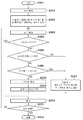
본 실시예에 따른 안저 촬상장치의 처리를 도 7의 플로차트를 참조하여 설명한다. 스텝 S101에서, 안저 촬상장치의 제어 동작을 시작한다. 스텝 S102에 있어서, 상기 장치는 수차를 다항식의 함수인 제르니케 함수로 나타내기 위해서 N차(N은 자연수(이하, 마찬가지))까지의 계수를 설정한다. 본 실시예에서는, 장치는 수차의 보정에서 사용하는 제르니케 함수의 계수를 1차∼4차의 저차의 계수로 설정한다. 그리고, 장치는 (이하에 설명하는) 스텝 S103로부터 스텝 S109까지의 보상 광학의 기본 절차를 실행한다. 이하는 보상 광학의 기본적인 절차의 개요이다. 스텝 S103에서, 파면 센서(115)는 수차를 측정한다. 측정한 결과에 의거해서 스텝 S108에서 보상 광학 제어부(116)는 보정량을 계산한다. 그리고, 장치는 스텝 S109에서, 보상 광학 제어부(116)의 제어 하에 파면 보정 디바이스(108)를 반복해 구동한다.The processing of the funduscopic imaging apparatus according to the present embodiment will be described with reference to the flowchart of FIG. In step S101, the control operation of the fundal image capturing apparatus is started. In step S102, the apparatus sets a coefficient up to an Nth order (N is a natural number (the same applies to the following description)) in order to express the aberration as a Zernike function as a function of a polynomial. In this embodiment, the apparatus sets the coefficients of the Zernike function used in the correction of the aberrations to the coefficients of the first order to the fourth order. Then, the apparatus executes the basic procedure of the compensation optics from step S103 to step S109 (to be described below). The following is an overview of the basic procedure of compensation optics. In step S103, the
다음에, 보상 광학의 각 스텝의 내용을 설명한다. 스텝 S103에서, 파면 센서(115)는 수차를 측정하여, 수차량을 취득한다. 본 실시예에 있어서, 수차량은, 취득한 수차로부터 얻은 파면의 디스터번스(disturbance)의 총량을 나타낸다. 그렇지만, 이 양은 기준 파면(평탄 파면)으로부터의 어긋남의 총량 등을 나타낸다. 스텝 S1004(제1 판정 공정)에서, 보상 광학 제어부(116)는, 스텝 S103에서 취득한 수차량이 미리 설정된 제1 기준값 미만(기준 1)인지의 여부를 판정한다. 제1 기준값(기준 1)은 안저 촬상장치의 고유한 값이어도 좋고, 촬상자가 설정해도 좋다. 수차량이 제1 기준값(기준 1)보다 작은 경우(스텝 S104에서 Yes), 처리는 스텝 S110로 진행된다. 한편, 수차량이 제1 기준값(기준 1)이상인 경우(스텝 S104에서 No), 처리는 스텝 S105로 진행되어, 스텝 S105 이후의 처리가 실행된다.Next, the content of each step of the compensation optical system will be described. In step S103, the
스텝 S105(제2 판정 공정)에 있어서, 보상 광학 제어부(116)는, 측정된 수차량(예를 들면, 전회에 측정된 수차량)과 이번의 측정에 의해 취득된 수차량의 차분으로부터, 수차량의 변화를 취득한다. 그리고, 보상 광학 제어부(116)는, 수차량의 변화가 제2 기준값 미만(기준 2)인지의 여부를 판정한다. 제2 기준값(기준 2)으로서는, 예를 들면, 전회의 수차량과 이번의 수차량의 차분의 변화율을 나타내는 값이나 촬상자에 의해 미리 정해진 값 등을 사용할 수 있다. 수차량의 변화가 제2 기준값 미만(기준 2)인 경우(스텝 S105에서 Yes), 보상 광학 제어부(116)는 현재 사용하고 있는 차수의 계수에서는 충분히 보정을 행할 수 없을 가능성이 높다고 판단한다. 그래서, 처리를 스텝 S107로 진행시킨다. 스텝 S107에 있어서, 보상 광학 제어부(116)는 측정된 수차량과 보정된 후에 측정된 수차량과의 사이의 변화에 따라, N차의 다항식의 함수를, N차보다 높은 차수를 포함하는 M차(M은 M>N의 관계를 충족시키는 자연수(이하 마찬가지))의 함수로 변경한다. 보상 광학 제어부(116)는 수차보정에서 사용하는 제르니케 함수의 계수를 1차 내지 6차의 고차의 차수를 포함하는 함수의 계수로 설정한다. 그리고, 처리가 스텝 S103로 되돌아간다. 한편, 본 실시예에서는 고차의 계수로서 1차 내지 6차의 계수의 설정을 예시하고 있다. 그렇지만, 저차의 계수로서 1차 내지 4차의 계수가 설정되어 있을 경우, 고차의 계수는 1차 내지 6차의 계수에 한정되지 않는다. 예를 들면, 1차 내지 4차의 계수를 포함하는 1차 내지 5차의 계수 또는 1차 내지 6차의 계수를 설정하는 것이 가능하다. 또한, 6차의 계수가 상한의 계수로서 한정되는 것이 아니고, 사용하는 계수는 더욱 고차의 계수를 포함하는 것도 가능하다.In step S105 (second determination step), the compensation
스텝 S103 이후의 스텝에 있어서, 보상 광학 제어부(116)는 전번에 실행된 스텝 S107에서 설정된 고차의 계수를 포함하는 함수를 사용해서 같은 수차 보정의 처리를 행한다.In the step after step S103, the compensation
한편, 보상 광학 제어부(116)는 스텝 S105에서 수차량의 변화가 제2 기준값 이상(기준 2)인 경우(스텝 S105에서 No), 현재 사용하고 있는 차수의 함수에 대응하는 수차 보정이 충분하지 않다고 판단한다. 따라서, 보상 광학 제어부(116)는, 처리를 스텝 S106로 진행시키고, 현재 사용하고 있는 차수의 계수를 변경하지 않고 보정을 계속한다.On the other hand, when the change of the aberration amount is equal to or more than the second reference value (reference 2) (No in step S105), the compensation
스텝 S106(제3 판정 공정)에 있어서, 보상 광학 제어부(116)는 수차 보정의 시작으로부터의 보정 제어의 반복 회수가 제3 기준값(기준 3)을 넘는지 아닌지를 판정한다. 반복 회수가 제3 기준값(기준 3)을 넘는 경우(스텝 S106에서 Yes)에, 보상 광학 제어부(116)는 처리를 스텝 S107로 진행시킨다. 스텝 S107에 있어서, 보상 광학 제어부(116)는 파면 센서(115)의 측정 결과에 따라 소정의 차수의 함수(제1의 함수)를, 소정의 차보다도 고차의 차수를 포함하는 함수(제2의 함수)로 변경한다. 이 경우, 파면 센서(115)의 측정 결과에는, 파면 센서(115)에 의해 측정된 수차량과, 이미 측정되어 있는 수차량과 파면 센서(115)에 의해 측정된 수차량과의 차분으로부터 취득한 수차량의 변화 중 적어도 한 개가 포함된다. 보상 광학 제어부(116)는 사용하는 제르니케 함수의 계수를, 예를 들면 1차 내지 6차의 고차를 포함하는 차수를 갖는 함수의 계수로 변경하고, 처리는 스텝 S103로 되돌아간다. 한편, 스텝 S106에서는, 보정 제어의 반복 회수를 제3 기준으로서 사용한 보상 광학 제어부(116)에 의한 제어 결과를 예시했지만, 본 발명의 요지는 이 예에 한정되지 않는다. 예를 들면, 보정 제어의 처리의 시작으로부터의 시간의 경과를 나타내는 반복 시간을 제3 기준으로서 사용하여 제어 결과를 취득하는 것도 가능하다. 보상 광학 제어부(116)는, 처리의 시작으로부터의 시간의 경과를 측정 가능한 계시(計時)부(예를 들면, 타이머)를 구비하고, 보정 제어의 처리의 시작으로부터 소정의 반복 시간이 경과했는지 아닌지를 판정한다(S106). 그리고, 처리의 시작으로부터 소정의 반복 시간이 경과한 후에(스텝 S106에서 Yes), 처리는 스텝 S107로 진행된다. 그리고, 스텝 S107에 있어서, 보상 광학 제어부(116)는, 파면 센서(115)의 측정 결과에 따라 소정의 차수의 함수(제1의 함수)를, 소정의 차수보다 높은 차수를 포함하는 차수를 갖는 함수(제2의 함수)로 변경하는 처리를 실행한다.In step S106 (third determination step), the compensation
한편, 보상 광학 제어부(116)는, 스텝 S106에 있어서, 수차보정의 시작으로부터의 보정 제어의 반복 회수가 제3 기준값 이하(기준 3)라고 판정될 경우(스텝 S106에서 No), 처리는 스텝 S108로 진행된다. 스텝 S108에서, 보상 광학 제어부(116)는 변경된 함수에 의해 나타내는 수차를 보정하기 위한 보정량을 산출한다. 스텝 S109에 있어서, 장치는 보상 광학 제어부(116)의 제어 하에 파면 보정 디바이스(108)를 구동하고, 변경된 함수에 의해 나타낸 수차를 보정하기 위한 보정처리를 실행한다. 그리고, 처리는 스텝 S103로 되돌아간다. 장치는, 스텝 S104에 있어서, 보상 광학 제어부(116)가 수차량이 제1 기준값 미만(기준 1)이라고 판정할 때까지, 스텝 S103로부터 스텝 S109까지의 처리를 반복한다.On the other hand, when it is determined in step S106 that the number of repetitions of the correction control from the start of the aberration correction is equal to or less than the third reference value (reference 3) (No in step S106), the compensation
스텝 S110에 있어서, 안저 촬상장치는 피검안의 안저를 촬상하고, 스텝 S111에서 처리를 종료했는지 아닌지를 판정한다. 종료 요구가 입력되지 않은 경우(스텝 S111에서 No), 처리가 스텝 S103로 되돌아가서, 스텝 S103로부터 스텝 S109까지의 보상 광학의 처리를 행하고, 스텝 S110에서 촬상을 행한다. 도 7에 나타낸 안저 촬상장치의 제어 동작의 예에서는, 장치는 촬상의 처리와 수차보정의 처리를 연속해서 행한다. 그렇지만, 양쪽 처리를 동시에 행하는 것도 가능하다. 장치가 스텝 S111에서 종료 요구를 확인했을 경우(스텝 S111에서 Yes), 장치는 스텝 S112에서 제어 동작을 종료한다.In step S110, the funduscopic imaging apparatus images the eye fundus of the eye to be examined and determines whether or not the processing is terminated in step S111. If the end request is not input (No in step S111), the process returns to step S103 to perform the compensation optical processing from step S103 to step S109, and imaging is performed in step S110. In the example of the control operation of the funduscopic imaging apparatus shown in Fig. 7, the apparatus continuously performs the imaging process and the aberration correction process. However, it is also possible to perform both processes at the same time. When the apparatus confirms the end request in step S111 (Yes in step S111), the apparatus ends the control operation in step S112.
수차 보정의 처리에 있어서는, 변조량(보정량)의 계산 시간이 총 처리 시간 중 매우 높은 비율을 차지하기 때문에, 계산량의 경감이 처리의 고속화에 매우 유효하다. 제르니케 함수의 1차 내지 4차의 차수의 계수를 이용해서 변조량을 계산할 경우에 걸리는 시간은, 제르니케 함수의 1차 내지 6차의 차수의 계수를 이용해서 변조량을 계산할 경우에 걸리는 시간과 거의 2배 가까이 다르다. 본 실시예와 같이, 보정 개시 시에 제르니케 함수의 1차로부터 4차까지의 차수의 계수를 이용해서 보정을 행함으로써 처리가 대단히 고속화된다. 측정 수차의 대부분이 제르니케 함수의 1차 내지 4차의 차수에 대응하는 수차인 경우에는, 제르니케 함수의 1차로부터 4차까지의 차수의 계수를 사용하여 수차를 충분히 보정하는 것이 가능하다. 따라서, 처리가 스텝 S104로부터 스텝 S110로 진행되어, 신속히 촬상을 시작할 수 있다. 또한, 제르니케 함수의 1차로부터 4차까지의 차수의 계수를 이용해서 충분한 보정을 행할 수 없는 경우에는, 장치는 보정할 수 없었던 잔존 수차만을 제르니케 함수의 고차의 차수를 포함하는 차수의 계수를 사용해서 처리하므로, 적은 보정 회수로 촬영 가능한 상태에 도달한다. 이러한 처리를 행함으로써, 처리의 시작부터 보다 고차의 차수의 계수를 포함하는 계수를 이용해서 반복 제어보다 빠른 촬상을 가능하게 하는 수차에 도달하는 것이 가능해진다. 본 실시예에서는 수차의 모델화에 제르니케 함수를 사용했다. 그렇지만, 장치가 그 밖의 함수계를 사용하는 경우도 같다.In the aberration correction processing, since the calculation time of the modulation amount (correction amount) occupies a very high proportion of the total processing time, the reduction of the calculation amount is very effective for increasing the processing speed. The time taken to calculate the modulation amount using the coefficients of the first to fourth order of the Zernike function is determined by the time taken to calculate the modulation amount using the coefficients of the first to sixth order of the Zernike function Which is almost twice as much. As in the present embodiment, the correction is performed by using the coefficient of the order from the first order to the fourth order of the Zernike function at the start of the correction, and the process is greatly speeded up. When a large part of the measurement aberration is an aberration corresponding to the order of the first to fourth orders of the Zernike function, it is possible to sufficiently correct the aberration by using the coefficient of the order from the first order to the fourth order of the Zernike function. Therefore, the processing advances from step S104 to step S110, and imaging can be started quickly. In the case where sufficient correction can not be performed by using the coefficient of order from the first order to the fourth order of the Zernike function, only the residual aberration that can not be corrected is corrected by the coefficient of order including the order of the higher order of the Zernike function So that the state of being able to take a picture with a small number of corrections is reached. By performing such processing, it becomes possible to reach the aberration enabling the imaging to be performed faster than the iterative control by using the coefficient including the coefficients of the higher order degree from the beginning of the processing. In the present embodiment, a Zernike function is used for modeling aberration. However, the same is true for devices that use other functional systems.
본 실시예에 의하면, 보정상태에 따라 적절한 보정방법을 취하는 것이 가능해지므로, 수차 보정의 처리가 고속화되어서 신속한 촬상이 가능해진다.According to this embodiment, it is possible to take an appropriate correction method according to the correction state, so that the processing of the aberration correction is speeded up, and rapid imaging is possible.
(제2 실시예)(Second Embodiment)
제2 실시예에 따른 안저 촬상장치의 처리를 도 8의 플로차트를 사용하여 설명한다. 기본적인 장치 구성은 제1 실시예와 같다. 본 실시예는, 피검안의 수차 중에서 큰 수차에 대응하는 계수를 수차 보정에 지배적인 계수로서 사용해서 수차보정을 행하는 것을 특징으로 한다. 스텝 S201에서는, 안저 촬상장치가 제어 동작을 시작한다. 스텝 S213에서는, 장치가 보정 전의 수차를 측정한다. 보상 광학 제어부(116)는 측정한 수차를 제르니케 함수의 1차 내지 6차의 차수를 이용해서 모델화하고, 모델화한 항(차수) 중 큰 계수를 갖는 항(차수)을 확인한다. 그리고, 스텝 S202에 있어서, 장치는 보정 제어에 사용하는 계수로서, 스텝 S213에서 확인한 큰 값을 갖는 항(차수)의 계수를 설정한다. 그리고, 장치는 보상 광학의 기본적인 절차를 실행한다.The processing of the funduscopic imaging apparatus according to the second embodiment will be described with reference to the flow chart of Fig. The basic device configuration is the same as the first embodiment. The present embodiment is characterized in that the aberration correction is performed by using a coefficient corresponding to a large aberration in the aberration of the eye to be examined as a coefficient dominant to the aberration correction. In step S201, the funduscopic imaging apparatus starts the control operation. In step S213, the apparatus measures the aberration before correction. The compensation
이하는 보상 광학의 기본적인 절차의 개요이다. 스텝 S203에서는, 파면 센서(115)가 수차를 측정한다. 보상 광학 제어부(116)는 측정한 결과를 바탕으로 스텝 S208에서 보정량을 계산한다. 그리고, 스텝 S209에서, 장치는 보상 광학 제어부(116)의 제어 하에 파면 보정 디바이스(108)를 반복해서 구동한다. 다음에, 보상 광학의 각 스텝의 내용을 설명한다. 스텝 S203에서, 파면 센서(115)에 의해 수차를 측정하고, 수차량을 취득한다.The following is an overview of the basic procedure of compensation optics. In step S203, the
스텝 S204에서, 보상 광학 제어부(116)는, 스텝 S203에서 취득한 수차량이 미리 설정된 제1 기준값 미만(기준 1)인지의 여부를 판정한다. 제1 기준값(기준 1)은 안저 촬상장치의 고유한 값이어도 좋고, 촬상자가 설정해도 좋다. 수차량이 제1 기준값(기준 1)보다 작은 경우(스텝 S204에서 Yes), 처리가 스텝 S110로 진행된다. 한편, 수차량이 제1 기준값(기준 1)이상인 경우(스텝 S204에서 No), 처리는 스텝 S205로 진행되어, 스텝 S205 이후의 스텝의 처리가 실행된다.In step S204, the compensation
스텝 S205에 있어서, 보상 광학 제어부(116)는 수차량의 변화가 제2 기준값(기준 2)을 넘는지 아닌지를 판정한다. 수차량의 변화가 제2 기준값 미만(기준 2)인 경우(스텝 S205에서 Yes), 보상 광학 제어부(116)는 현재 사용하고 있는 차수의 계수의 사용이 충분한 보정을 행할 수 없을 가능성이 높다고 판단한다. 그래서, 처리를 스텝 S207로 진행시킨다. 스텝 S207에 있어서, 보상 광학 제어부(116)는 사용하는 제르니케 함수의 계수를, 1차로부터 6차까지의 고차의 차수를 갖는 함수(고차의 보정계수를 갖는 함수)의 계수로 변경하고, 처리가 스텝 S203로 되돌아간다. 스텝 S203 이후의 스텝에 있어서, 보상 광학 제어부(116)는 스텝 S207에서 변경된 고차의 차수를 갖는 함수를 사용해서 같은 수차 보정의 처리를 행한다.In step S205, the compensation
한편, 보상 광학 제어부(116)는 스텝 S205에서 수차량의 변화가 제2 기준값(기준 2)이상이라고 판정한 경우(스텝 S205에서 No), 현재 사용하고 있는 함수의 계수에 대응하는 수차 보정이 충분하지 않는다고 판정한다. 따라서, 보상 광학 제어부(116)는, 처리를 스텝 S206로 진행시키고, 현재 사용하고 있는 차수의 계수를 변경하는 일없이 보정을 계속한다.On the other hand, if the compensation
스텝 S206에 있어서, 보상 광학 제어부(116)는 수차 보정의 시작으로부터의 보정 제어의 반복수가 제3 기준값(기준 3)을 넘는지 아닌지를 판정한다. 이 경우, 제3 기준값(기준 3)은, 미리 설정되어 있는 정수 N(N은 2이상의 자연수)이다. 반복 회수가 제3 기준값(기준 3)을 넘는 경우(스텝 S206에서 Yes)에, 보상 광학 제어부(116)는 처리를 스텝 S207로 진행시킨다. 스텝 S207에 있어서, 보상 광학 제어부(116)는 사용하는 제르니케 함수의 계수를 1차로부터 6차까지의 고차를 포함하는 차수의 계수(고차의 보정계수)로 변경하고, 처리는 스텝 S203로 되돌아간다.In step S206, the compensation
한편, 보상 광학 제어부(116)는 스텝 S206에서, 수차 보정의 시작으로부터의 보정 제어의 반복수가 제3 기준값(기준 3)이하라고 판정한 경우(스텝 S206에서 No), 처리는 스텝 S208로 진행된다. 스텝 S208에 있어서, 보상 광학 제어부(116)는 보정량을 계산한다. 스텝 S209에 있어서, 상기의 장치는 보상 광학 제어부(116)의 제어 하에 파면 보정 디바이스(108)를 구동한다. 그리고, 처리는 스텝 S203로 되돌아간다. 장치는 스텝 S204에 있어서, 보상 광학 제어부(116)가 수차량이 제1 기준값(기준1)보다 작다고 판정할 때까지, 스텝 S203로부터 스텝 S209까지의 처리를 반복한다.On the other hand, when the compensation
스텝 S210에 있어서, 안저 촬상장치는 피검안의 안저의 촬상을 행하고, 스텝 S211에서 처리의 종료 여부를 판정한다. 종료 요구가 입력되지 않은 경우(스텝 S211에서 No), 처리는 스텝 S203로 되돌아가서 스텝 S203로부터 스텝 S209까지의 보상 광학의 처리를 행하고, 스텝 S210에서 촬상을 행한다. 도 8에 나타낸 안저 촬상장치의 제어의 예에서는, 장치는 촬상의 처리와 수차 보정의 처리를 연속해서 행한다. 그렇지만, 양쪽 처리를 동시에 행하는 것도 가능하다. 장치가 스텝 S211에서 종료 요구를 확인한 경우(스텝 S211에서 Yes), 장치는 스텝 S212에서 제어 동작을 종료한다.In step S210, the funduscopic imaging apparatus performs imaging of the fundus of the eye to be examined, and determines whether or not the processing ends in step S211. If the end request is not inputted (No in step S211), the process returns to step S203 to perform the compensation optical processing from step S203 to step S209, and the imaging is performed in step S210. In the control example of the funduscopic imaging apparatus shown in Fig. 8, the apparatus continuously performs the imaging process and the aberration correction process. However, it is also possible to perform both processes at the same time. When the apparatus confirms the termination request in step S211 (Yes in step S211), the apparatus ends the control operation in step S212.
보정 개시 시에 보정하는 차수를, 수차가 큰 부분에 한정함으로써, 처리가 매우 고속화된다. 큰 수차를 갖는 차수가 보정 대상이기 때문에, 이들의 차수를 보정함으로써, 촬영가능한 수차 상태에 도달할 가능성이 높다. 이것에 의해 신속히 촬상을 시작할 수 있다. 또한, 초기의 설정으로 수차를 보정할 수 없는 경우에도, 장치는 보정할 수 없었던 잔존 수차만을 보정하기 때문에, 처리의 시작으로부터 높은 차수를 포함하는 차수의 계수를 사용해서 반복 제어하는 것보다도 신속히 촬상 가능한 수차 상태에 도달하는 것이 가능해진다. 본 실시예에서는 수차의 모델화에 제르니케 함수를 사용한다. 장치가 그 밖의 함수계를 사용하는 경우도 같다.By limiting the degree to be corrected at the start of correction to a portion having a large aberration, the processing speed is extremely high. Since the order with large aberrations is the object to be corrected, there is a high possibility of reaching a photographable aberration state by correcting these orders. Thus, imaging can be started quickly. Further, even when the aberration can not be corrected by the initial setting, since the apparatus corrects only the remaining aberrations that could not be corrected, It becomes possible to reach a possible aberration state. In this embodiment, a Zernike function is used for modeling aberration. The same is true for devices that use other functional systems.
본 실시예에 의하면, 피검안의 수차상태에 따라 적절한 보정방법을 이용하는 것이 가능해져, 수차 보정 처리가 고속화되어서 신속한 촬상이 가능해진다.According to this embodiment, it is possible to use an appropriate correction method in accordance with the aberration state of the eye to be examined, and the aberration correction processing is speeded up, enabling rapid imaging.
(제3 실시예)(Third Embodiment)
제3 실시예에 따른 안저 촬상장치의 처리를 도 9의 플로차트를 참조하여 설명한다. 기본적인 장치 구성은 제1 실시예와 같다. 본 실시예는, 안저 촬상을 허용하는 수차까지 보정이 완료한 후에 저수차 상태를 유지하는 구성에 있어서, 유지 정밀도를 향상시키기 위해서 보정 제어를 고속화하는 것을 특징으로 한다.The processing of the funduscopic imaging apparatus according to the third embodiment will be described with reference to the flowchart of FIG. The basic device configuration is the same as the first embodiment. The present embodiment is characterized in that the correction control is performed at a high speed in order to improve the holding precision in a configuration in which the low aberration state is maintained after the correction to the aberration allowing the funduscopic imaging is completed.
스텝 S301에서, 안저 촬상장치가 제어 동작을 시작한다. 스텝 S302에 있어서, 장치는 수차를 다항식의 함수인 제르니케 함수로 나타내기 위해서 N차까지의 계수를 설정한다. 본 실시예에서는, 장치는 수차보정에서 사용하는 제르니케 함수의 계수를 1차∼4차의 저차의 계수로 설정한다. 그리고, 장치는 (이하에 설명하는) 스텝 S303로부터 스텝 S309까지의 보상 광학의 기본 절차를 실행한다. 이하는 보상 광학의 기본적인 절차의 개요이다. 스텝 S303에서, 파면 센서(115)에 의해 수차를 측정한다. 측정한 결과를 바탕으로 스텝 S308에서 보상 광학 제어부(116)에 의해 보정량을 계산한다. 그리고, 스텝 S309에서, 장치는 보상 광학 제어부(116)의 제어 하에 파면 보정 디바이스(108)를 반복해서 구동한다.In step S301, the funduscopic imaging apparatus starts the control operation. In step S302, the apparatus sets the coefficients up to the Nth order to express the aberration as a Zernike function, which is a function of the polynomial. In this embodiment, the apparatus sets the coefficients of the Zernike function used in the aberration correction to the coefficients of the first order to the fourth order lower. Then, the apparatus executes the basic procedure of the compensation optics from step S303 to step S309 (to be described below). The following is an overview of the basic procedure of compensation optics. In step S303, the
다음에, 보상 광학의 각 스텝의 내용을 설명한다. 스텝 S303에서, 파면 센서(115)에 의해 수차를 측정하고, 수차량을 취득한다.Next, the content of each step of the compensation optical system will be described. In step S303, the
스텝 S304에서, 보상 광학 제어부(116)는, 스텝 S303에서 취득한 수차량이 미리 설정된 제1 기준값(기준 1) 미만인지의 여부를 판정한다. 제1 기준값(기준 1)은 안저 촬상장치의 고유한 값이어도 좋고, 촬상자가 설정해도 좋다. 수차량이 제1 기준값(기준 1) 미만인 경우(스텝 S304에서 Yes), 처리가 스텝 S310로 진행된다. 한편, 수차량이 제1 기준값(기준 1) 이상인 경우(스텝 S304에서 No), 처리는 스텝 S305로 진행되어, 스텝 S305 이후의 처리가 실행된다. 보상 광학 제어부(116)는, 제1 실시예의 스텝 S105 및 S106의 처리와 같이, 스텝 S305 및 S306에서 수차량의 변화율과 반복 회수를 판정한다. 보상 광학 제어부(116)는 각 값을 그에 대응하는 기준값과 비교한다. 그들이 서로 일치하면(스텝 S305에서 Yes, 스텝 S306에서 Yes), 처리를 스텝 S307로 진행시킨다. 스텝 S307에 있어서, 보상 광학 제어부(116)는 측정된 수차량과, 보정된 후에 측정된 수차량과의 사이의 변화에 따라, N차(N은 자연수) 함수를, N차보다도 높은 차수를 포함하는 M차(M은 M > N의 관계를 충족시키는 자연수) 함수로 변경한다. 보상 광학 제어부(116)는 사용하는 제르니케 함수의 계수를, 1차 내지 6차의 고차의 차수를 갖는 함수의 계수로 설정한다. 그리고, 처리는 스텝 S103로 되돌아간다. 한편, 본 실시예에서는, 고차의 계수로서 1차 내지 6차의 계수의 설정을 예시하고 있다. 그렇지만, 저차의 계수로서 1차 내지 4차의 계수가 설정되어 있는 경우, 고차의 계수는 1차 내지 6차의 계수에 한정되지 않는다. 예를 들면, 1차 내지 4차의 계수를 포함하는 1차 내지 5차의 계수 또는 1차 내지 6차의 계수를 설정하는 것이 가능하다. 또한, 6차의 계수가 상한의 계수로서 한정되는 것이 아니고, 사용하는 계수는 더욱 고차의 계수를 포함하는 것도 가능하다.In step S304, the compensation
한편, 스텝 S305 및 S306에 있어서, 보상 광학 제어부(116)가 각각의 기준값과 비교해서 각 값이 설정된 조건과 일치하지 않는다고 판정한 경우(스텝 S305에서No, 스텝 S306에서 No), 처리가 스텝 S308로 진행된다. 스텝 S308에 있어서, 보상 광학 제어부(116)는 보정량을 계산한다. 스텝 S309에 있어서, 장치는 보상 광학 제어부(116)의 제어 하에 파면 보정 디바이스(108)를 구동한다. 그리고, 처리는 스텝 S303로 되돌아간다. 스텝 S304에 있어서는, 보상 광학 제어부(116)가 수차량이 제1 기준값(기준 1) 미만이라고 판정할 때까지, 스텝 S303로부터 스텝 S309까지의 처리가 반복해서 행해진다.On the other hand, when the compensation
스텝 S310에 있어서, 안저 촬상장치는 피검안의 안저의 촬상을 행하고, 스텝 S311에서 처리 종료 여부를 판정한다. 스텝 S311에서, 장치가 종료 요구를 확인한 경우(스텝 S311에서 Yes), 스텝 S312에서 제어 동작을 종료한다.In step S310, the funduscopic imaging apparatus performs imaging of the fundus of the eye to be examined, and determines whether or not the process has ended in step S311. In step S311, if the apparatus confirms the termination request (Yes in step S311), the control operation is terminated in step S312.
한편, 보상 광학 제어부(116)가 스텝 S311에서, 종료 요구가 입력되지 않았다고 판정한 경우(스텝 S311에서 No), 처리는 스텝 S314로 진행된다. 스텝 S314에서는, 보상 광학 제어부(116)가 측정한 수차로부터 큰 변화(변동)를 나타내는 차수의 계수를 선택하고, 그 차수의 계수를 보정에 사용하는 계수로서 설정한다. 변동량이 큰 몇 개의 계수 혹은 일정 이상의 변동량에 대응한 차수의 계수를, 보정에 사용하는 계수로서 설정하는 것이 가능하다. 예를 들면, 산동(散瞳)하고 있지 않은 눈의 측정에 있어서는, 눈의 굴절 조정이 항상 변동하기 때문에, 고화질 촬상을 행하기 위해서는, 이 굴절 상태를 추종할 필요가 있다. 이 경우에, 저차의 수차의 변동이 크므로, 수차 보정을 저차의 계수를 사용해서 행함으로써 추종 성능이 향상한다. 또한, 누액의 상태에 따라 고차의 수차가 변동하는 것도 알려져 있다. 그러므로, 고차의 수차 변동이 큰 경우에, 고차의 계수를 사용해서 수차 보정을 행하면 된다.On the other hand, if the compensation
계수를 설정한 후, 장치는 스텝 S303 이후의 보상 광학의 기본 처리를 행하고, 스텝 S310에서 다음 촬상 동작을 행한다. 도 9에 나타낸 안저 촬상장치의 제어동작의 예에서는, 장치는 촬상의 처리와 수차보정의 처리를 연속해서 행한다. 그렇지만, 양쪽 처리를 동시에 행하는 것도 가능하다.After setting the coefficient, the apparatus performs the basic processing of the compensation optical system after step S303, and performs the next imaging operation in step S310. In the example of the control operation of the funduscopic imaging apparatus shown in Fig. 9, the apparatus continuously performs imaging processing and aberration correction processing. However, it is also possible to perform both processes at the same time.
본 실시예 에 의하면, 연속 촬상 시의 수차 보정의 추수성이 향상하고, 고화질의 복수의 화상을 단시간으로 촬상하는 것이 가능해진다.According to this embodiment, the follow-up performance of the aberration correction at the time of continuous imaging is improved, and it becomes possible to capture a plurality of images of high image quality in a short time.
(제4 실시예)(Fourth Embodiment)
제4 실시예에 따른 안저 촬상장치의 구성을, 도 10을 참조해서 설명한다. 도 10에 나타낸 기본적인 구성은 제1 실시예의 안저 촬상장치와 같아서, 같은 구성요소에는 동일한 참조번호를 부착하고 있다. 제4 실시예에 따른 안저 촬상장치에 있어서는, 파면 보정 디바이스(108)가 제1의 파면 보정 디바이스(108-1)와 제2의 파면 보정 디바이스(108-2)로 구성된다. 또한, 안저 촬상장치는, 제1의 파면 보정 디바이스(108-1)와 제2의 파면 보정 디바이스(108-2)를 광학적으로 결합하기 위한 반사 미러 107-5과 107-6를 구비하고 있다. 이 경우, 제1의 파면 보정 디바이스(108-1)는 주로 저차의 수차를 보정하도록 설계되어 있다. 예를 들면, 이 디바이스로서 엘리먼트(element)의 수가 적은 가변형 미러가 적합하게 사용될 수 있다. 제2의 파면 보정 디바이스(108-2)는 고차의 수차를 포함하는 수차를 보정하도록 설계되어 있다. 이 디바이스로서는 엘리먼트의 수가 많은 가변형 미러나 액정소자를 사용한 공간 위상 변조기(반사형 액정 광변조기)가 적합하게 사용될 수 있다. 보상 광학 제어부(116)는, 파면 센서(115)와 제1의 파면 보정 디바이스(108-1)가 행하는 처리, 또는 파면 센서(115)와 제1의 파면 보정 디바이스(108-1)와 제2의 파면 보정 디바이스(108-2)가 행하는 처리를 반복해 제어한다.The configuration of the funduscopic imaging apparatus according to the fourth embodiment will be described with reference to Fig. The basic configuration shown in Fig. 10 is the same as that of the funduscopic imaging apparatus of the first embodiment, and the same reference numerals are attached to the same constituent elements. In the funduscopic imaging apparatus according to the fourth embodiment, the
제4 실시예의 안저 촬상장치의 처리를 도 11의 플로차트를 사용하여 설명한다. 스텝 S401에서, 안저 촬상장치는 제어동작을 시작한다. 스텝 S402에 있어서, 장치는 수차를 다항식의 함수인 제르니케 함수로 나타내기 위해서 N차(N은 자연수)까지의 계수를 설정한다. 본 실시예에서는, 장치가 수차 보정에서 사용하는 제르니케 계수를 1차∼2차의 계수로 설정한다. 그리고, 장치는 (이하에 설명하는) 스텝 S403로부터 스텝 S409까지의 보상 광학의 기본 절차를 실행한다. 이하는 보상 광학의 기본적인 절차의 개요이다. 스텝 S403에서, 파면 센서(115)에 의해 수차를 측정한다. 스텝 S408(제1의 산출 공정)에서, 보상 광학 제어부(116)가 측정 결과에 근거해서 제1의 파면 보정 디바이스(108-1)의 보정량을 산출한다. 한편, 스텝 S408에 있어서, 보상 광학 제어부(116)는 제2의 파면 보정 디바이스(108-2)의 보정량을 산출하지 않는다. 보정량을 산출하는 대상을 제1의 파면 보정 디바이스(108-1)로 한정함으로써, 계산량을 저감하는 것이 가능하게 되고, 처리가 매우 고속화된다. 스텝 S409에서는, 보상 광학 제어부(116)의 제어 하에 제1의 파면 보정 디바이스(108-1)의 구동이 반복해서 행해진다.The processing of the funduscopic imaging apparatus of the fourth embodiment will be described with reference to the flow chart of Fig. In step S401, the funduscopic imaging apparatus starts the control operation. In step S402, the apparatus sets coefficients to the Nth order (N is a natural number) in order to express the aberration as a Zernike function which is a function of a polynomial. In this embodiment, the Zernike coefficients used by the apparatus in the aberration correction are set as coefficients of the first to second orders. Then, the apparatus executes the basic procedure of the compensation optics from step S403 to step S409 (described below). The following is an overview of the basic procedure of compensation optics. In step S403, the
다음에, 보상 광학의 각 스텝의 내용을 설명한다. 스텝 S403에서, 파면 센서(115)에 의해 수차를 측정하고, 수차량을 취득한다. 스텝 S404에서, 보상 광학 제어부(116)는, 스텝 S403에서 취득한 수차량이 미리 설정된 제1 기준값 미만(기준 1)인지의 여부를 판정한다. 제1 기준값(기준 1)은 안저 촬상장치의 고유한 값이어도 좋고, 촬상자가 설정해도 좋다. 수차량이 제1 기준값(기준 1)보다 작은 경우(스텝 S404에서 Yes), 처리가 스텝 S410로 진행된다. 한편, 수차량이 제1 기준값(기준 1)이상인 경우(스텝 S404에서 No), 처리는 스텝 S405로 진행되어, 스텝 S405 이후의 처리가 실행된다.Next, the content of each step of the compensation optical system will be described. In step S403, the
보상 광학 제어부(116)는 제1 실시예의 스텝 S105 및 S106의 처리와 같이, 스텝 S405 및 S406에서 수차량의 변화율과 반복 회수를 판정한다. 보상 광학 제어부(116)는 각각의 값과 그에 대응하는 기준값을 비교한다. 그들이 서로 일치하면(스텝 S405에서 Yes, 스텝 S406에서 Yes), 처리를 스텝 S407로 진행시킨다. 스텝 S407에 있어서, 보상 광학 제어부(116)는 측정된 수차량과, 보정된 후에 측정된 수차량과의 사이의 변화에 따라, N차(N은 자연수)의 함수를, N차보다도 높은 차수를 포함하는 M차(M은 M>N의 관계를 충족시키는 자연수)의 함수로 변경한다. 보상 광학 제어부(116)는 사용하는 제르니케 함수의 계수를 1차로부터 6차까지의 고차를 포함하는 함수의 계수로 설정한다. 한편, 본 실시예에서는 고차의 계수로서 1차 내지 6차의 계수의 설정을 예시하고 있다. 그렇지만, 저차의 계수로서 1차로부터 2차까지의 계수가 설정되어 있는 경우, 고차의 계수는 1차 내지 6차의 계수에 한정되지 않는다. 예를 들면, 1차 및 2차의 계수를 포함하는 1차 내지 3차의 계수, 1차 내지 4차의 계수, 및 1차 내지 5차의 계수 또는 1차 내지 6차의 계수를 설정하는 것이 가능하다. 또한, 6차의 계수가 상한의 계수로서 한정되는 것이 아니고, 사용하는 계수는 고차의 계수를 포함하는 것도 가능하다. 고차로서의 M차는, 항상 저차로서 N차의 계수를 모두 포함해야 필요가 없다. N차의 계수로서, 예를 들면, 1차 및 2차의 계수가 설정되었을 경우, N차의 계수의 일부인 2차의 계수와, N차의 계수보다도 고차의 계수(예를 들면, 3차 및 4차의 계수)를 포함하도록 계수를 설정하여, 수차를 나타내는 함수의 차수를 정의하는 것도 가능하다.The compensation
보상 광학 제어부(116)는, 스텝 S405 및 S406에서, 각각의 기준값과 비교해서 각각의 값이 설정된 조건과 일치하지 않는다고 판정한 경우(스텝 S405에서 No, 스텝 S406에서 No), 보상 광학 제어부(116)는 소정의 차수(예를 들면, N차)의 다항식에 의해 나타낸 함수(제1의 함수)를 변경하지 않는다고 판정한다.If the comparison
처리가 스텝 S408로 진행된다. 스텝 S408(제3의 산출 공정)에 있어서, 보상 광학 제어부(116)는 제1의 파면 보정 디바이스(108-1)의 보정량을 산출한다. 스텝 S409(제3의 수차보정공정)에 있어서, 장치는 보상 광학 제어부(116)의 제어 하에 제1의 파면 보정 디바이스(108-1)를 구동하고, S408에서 산출된 보정량에 의거하여 소정의 차수(예를 들면, N차)의 수차를 보정한다. 그리고, 처리는 스텝 S403로 되돌아간다. 장치는 스텝 S404에 있어서, 보상 광학 제어부(116)가 수차량이 제1 기준값 미만(기준 1)이라고 판정할 때까지, 스텝 S403로부터 스텝 S409까지의 처리를 반복한다.The process proceeds to step S408. In step S408 (third calculation step), the compensation
스텝 S410에 있어서, 안저 촬상장치는 피검안의 안저의 촬상을 행하고, 스텝 S411에서 처리를 종료한다. 한편, 제1 실시예의 스텝 S111와 같이, 장치는 스텝 S412 전에 촬상 종료를 확인하고, 연속 촬상을 행하는 것도 가능하다.In step S410, the fundal-image-capturing device performs imaging of the fundus of the eye to be examined, and ends the process in step S411. On the other hand, as in step S111 of the first embodiment, the apparatus can confirm the end of image capture before step S412 and perform continuous image capture.
한편, 스텝 S407에 있어서, 제르니케 계수를 변경한 후, 장치는 사용하는 함수를, 소정의 차수(예를 들면, N차)의 함수(제1의 함수)보다도 고차의 차수(예를 들면, M차(M은 M>N인 자연수)를 포함하는 함수(제2의 함수)로 변경한다. 그리고, 처리는 스텝 S415로 진행된다. 스텝 S415로부터 S420까지의 처리는, 먼저 설명한 보상 광학의 기본 절차와 같은 처리이지만, 제1의 파면 보정 디바이스(108-1)뿐만 아니라 제2의 파면 보정 디바이스(108-2)도 파면 보정의 대상이 되는 점에서 상위하다.On the other hand, after changing the Zernike coefficients in step S407, the apparatus sets the function to be used to a higher order (for example, a first function) than a function of a predetermined order (for example, N-th order) (Second function) including the M-th order (M is a natural number with M > N), and the process proceeds to step S415. The processes from step S415 to step S420 are the same as those Process is the same as in the procedure, but the first wavefront correcting device 108-1 as well as the second wavefront correcting device 108-2 are also subjected to wavefront correction.
스텝 S415에 있어서, 파면 센서(115)에 의해 수차를 측정하고, 수차량을 취득한다. 스텝 S416에 있어서, 보상 광학 제어부(116)는, 스텝 S415에서 취득한 수차량이 미리 설정된 제1 기준값 미만(기준 1)인지의 여부를 판정한다. 수차량이 제1 기준값(기준 1)보다 작은 경우(스텝 S416에서 Yes), 처리가 스텝 S410로 진행된다. 스텝 S410에서 안저의 촬상을 행한 후, 장치는 스텝 S412에서 처리를 종료한다.In step S415, the
한편, 장치는 스텝 S416에서, 수차량이 제1 기준값(기준 1) 이상이라고 판정한 경우(스텝 S416에서 No), 처리는 스텝 S417로 진행되어, 스텝 S417 이후의 처리가 실행된다.On the other hand, when the apparatus determines in step S416 that the aberration amount is equal to or greater than the first reference value (reference 1) (No in step S416), the processing proceeds to step S417, and the processing after step S417 is executed.
스텝 S417에 있어서, 장치는 측정된 수차를, 소정의 차수보다도 고차의 계수를 갖는 함수로 나타낸다. 그리고, 보상 광학 제어부(116)는, 그 함수로 나타낸 수차에 대해서 제1의 파면 보정 디바이스(108-1)(제1의 수차 보정부)가 소정의 차수의 수차 보정을 행하는 보정량을 산출한다. 제1의 파면 보정 디바이스(108-1)가 저차의 수차만을 보정하므로, 보상 광학 제어부(116)는, 스텝 S415에서 측정된 수차 중에서 저차의 수차에 대한 보정량만을 스텝 S417에서 계산한다.In step S417, the apparatus displays the measured aberration as a function having a higher order coefficient than a predetermined order. Then, the compensation
스텝 S418(제2의 산출 공정)에 있어서, 장치는 측정된 수차를, 소정의 차수보다도 고차의 계수를 갖는 함수로 나타낸다. 그리고, 그 함수로 나타낸 수차에 대해서 제2의 파면 보정 디바이스(108-2)(제2의 수차 보정부)가, 소정 차수보다도 고차의 수차 보정을 행하는 보정량을 보상 광학 제어부(116)가 산출한다. 제2의 파면 보정 디바이스(108-2)는 고차의 수차만을 보정하므로, 보상 광학 제어부(116)는 스텝 S415에서 측정된 수차 중에서 고차의 수차에 대한 보정량만을 스텝 S148에서 계산한다.In step S418 (second calculating step), the apparatus displays the measured aberration as a function having a higher order coefficient than the predetermined order. Then, the compensation
스텝 S419(제1의 수차 보정 공정)에 있어서, 장치는 보상 광학 제어부(116)의 제어 하에서 제1의 파면 보정 디바이스(108-1)를 구동하여, 변경된 고차의 계수를 포함하는 함수로 나타낸 수차 중에서 소정 차수의 수차를 보정한다. 스텝 S420(제2의 수차 보정 공정)에 있어서, 장치는 제2의 파면 보정 디바이스(108-2)를 구동해서, 변경된 고차의 계수를 포함하는 함수로 나타낸 수차 중에서, 소정 차수보다도 고차의 차수를 갖는 수차를 보정한다.In step S419 (the first aberration correction step), the apparatus drives the first wave-front correction device 108-1 under the control of the compensation
스텝 S415 이후의 처리에 있어서, 장치는 2개의 파면 보정 디바이스를 동시에 제어하도록 구성되어 있다. 그렇지만, 장치는 스텝 S415 이후의 스텝에서는 제2의 파면 보정 디바이스만을 이용해서 수차 보정을 행하도록 구성될 수 있다. 이 경우, 스텝 S408 및 S409에 있어서, 제1의 파면 보정 디바이스에 의해 충분히 보정될 수 없었던 저차 및 고차의 수차를 포함하는 수차를 제2의 파면 보정 디바이스가 보정한다.In the process after step S415, the apparatus is configured to simultaneously control two wavefront compensation devices. However, the apparatus can be configured to perform the aberration correction using only the second wave front correction device in the step after step S415. In this case, in the steps S408 and S409, the second wavefront correction device corrects the aberration including the lower and higher order aberrations that could not be sufficiently corrected by the first wavefront correction device.
본 실시예에 의하면, 복수의 파면 보정 디바이스를 효율적으로 제어하는 것이 가능해서, 고화질의 화상을 신속히 촬상하는 것이 가능해진다.According to the present embodiment, it is possible to efficiently control a plurality of wave-front correction devices, and it becomes possible to quickly pick up a high-quality image.
(그 외의 실시예)(Other Embodiments)
본 발명의 국면들은, 상술한 실시예(들)의 기능들을 행하도록 메모리 디바이스 상에 기록된 프로그램을 판독 및 실행하는 시스템 또는 장치의 컴퓨터(또는 CPU 혹은 MPU와 같은 디바이스)에 의해서도 실현될 수 있고, 또 예를 들면 상술한 실시예의 기능을 행하도록 메모리 디바이스 상에 기록된 프로그램을 판독 및 실행함으로써 시스템 또는 장치의 컴퓨터에 의해 행해지는 방법의 스텝들에 의해 실현될 수 있다. 이 목적을 위해서, 이 프로그램을, 예를 들면 메모리 디바이스(예를 들면, 컴퓨터 판독가능한 매체)로서 기능을 하는 다양한 형태의 기록매체로부터 또는 네트워크를 통해서 컴퓨터에 제공한다.Aspects of the present invention may also be realized by a computer (or a device such as a CPU or MPU) of a system or apparatus that reads and executes a program recorded on a memory device to perform the functions of the above-described embodiment (s) , And also by steps of a method performed by a computer of the system or apparatus, for example, by reading and executing a program recorded on a memory device to perform the functions of the above-described embodiments. For this purpose, the program is provided to the computer from various types of recording media, for example functioning as a memory device (e.g., a computer readable medium) or via a network.
본 발명은 예시적인 실시 예를 참조하면서 설명되었지만, 본 발명은 이 개시된 예시적인 실시 예에 한정되는 것이 아니라는 것이 이해될 것이다. 이하의 특허청구범위의 범주는 모든 변형 및 균등구조 및 기능을 포함하도록 가장 넓게 해석되어야 할 것이다.While the present invention has been described with reference to exemplary embodiments, it is to be understood that the invention is not limited to the disclosed exemplary embodiments. The scope of the following claims is to be accorded the broadest interpretation so as to encompass all such modifications and equivalent structures and functions.
Claims (17)
상기 수차측정유닛에 의해 취득된 측정 결과와 상기 제어유닛에 의해 취득된 제어 결과 중 적어도 한 개에 따라, 수차를 나타내는 미리 정해진 차수를 포함하는 제1의 함수 및 상기 미리 정해진 차수보다 높은 차수를 포함하는 제2의 함수 중 하나를 선택하는 선택 단계와,
상기 선택 단계의 결과에 근거하여, 상기 제1의 함수 또는 상기 제2의 함수로 나타낸 수차를 보정하는 수차보정단계를 포함하는, 안저 촬상방법.
An aberration measurement unit for measuring the aberration of the reflected light acquired by irradiating the measurement object with the measurement light, an aberration correction unit for correcting the aberration of light in accordance with the measured aberration, and a processing of the aberration measurement unit and the aberration correction unit A control method for a funduscopic imaging method of a funduscopic imaging apparatus,
A first function including a predetermined order representing aberration and an order higher than the predetermined order according to at least one of the measurement result obtained by the aberration measurement unit and the control result acquired by the control unit Selecting one of the first and second functions to be performed;
And aberration correcting step of correcting the aberration represented by the first function or the second function based on the result of the selection step.
상기 수차측정유닛에 의해 취득된 측정 결과는, 측정된 수차량과, 이미 측정되어 있던 수차량과 상기 측정된 수차량과의 차분으로부터 취득된 수차량의 변화 중 적어도 한 개를 포함하고,
상기 제어유닛에 의해 취득된 제어 결과는, 상기 처리의 반복 회수 및 상기 처리의 시작으로부터의 시간 경과를 나타내는 반복 시간 중 하나인, 안저 촬상방법.
The method according to claim 1,
Wherein the measurement result acquired by the aberration measurement unit includes at least one of a measured aberration amount and a change in an aberration amount obtained from a difference between a previously measured aberration amount and the measured aberration amount,
Wherein the control result obtained by the control unit is one of a repetition number indicating the number of repetitions of the processing and a time lapse from the start of the processing.
상기 수차측정유닛으로 측정된 상기 반사광의 수차량이 제1 기준값 미만인지의 여부를 판정하는 제1 판정 단계와,
상기 수차량이 상기 제1 기준값 미만이 아닌 경우에, 상기 수차량의 변화가 제2 기준값 미만인지의 여부를 판정하는 제2 판정 단계를 더 구비하고,
상기 수차량의 변화가 상기 제2 기준값 미만이라고 판정되었을 경우, 상기 선택 단계에서, 상기 제2의 함수를 선택하는, 안저 촬상방법.
The method according to claim 1,
A first judging step of judging whether or not the number vehicle of the reflected light measured by the aberration measuring unit is less than a first reference value,
Further comprising a second determination step of determining whether or not the change in the number of vehicles is less than a second reference value when the number vehicle is not less than the first reference value,
Wherein the second function is selected in the selecting step when it is determined that the change in the number of times is less than the second reference value.
상기 수차량의 변화가 제2 기준값 미만이 아닌 경우에, 상기 수차보정유닛에 의한 처리의 반복 회수가 제3 기준값을 초과하는지 아닌지를 판정하는 제3 판정 단계를 더 포함하고,
상기 처리의 반복 회수가 상기 제3 기준값을 초과하는 것으로 판정되었을 경우, 상기 선택 단계에서, 상기 제2의 함수를 선택하는, 안저 촬상방법.
The method of claim 3,
Further comprising a third determination step of determining whether or not the number of repetitions of the processing by the aberration correction unit exceeds a third reference value when the change of the aberration amount is not less than the second reference value,
Wherein the second function is selected in the selecting step when it is determined that the number of repetitions of the processing exceeds the third reference value.
상기 처리가 미리 정해진 반복 회수만큼 반복된 후, 또는 상기 처리의 시작으로부터 미리 정해진 반복 시간이 경과한 후에, 상기 선택 단계에서, 상기 수차측정유닛에 의해 취득된 측정 결과에 따라 상기 제2의 함수를 선택하는, 안저 촬상방법.
The method according to claim 1,
After the process is repeated a predetermined number of times or after a predetermined repetition time elapses from the start of the process, in the selecting step, the second function is determined in accordance with the measurement result acquired by the aberration measurement unit Selecting a funduscopic imaging method.
상기 선택 단계에서 선택된 함수로 나타낸 수차를 보정하기 위한 보정량을 산출하는 산출 단계를 더 포함하는, 안저 촬상방법.
The method according to claim 1,
Further comprising a calculating step of calculating a correction amount for correcting the aberration represented by the function selected in the selecting step.
상기 수차보정유닛이, 제1의 수차보정유닛 및 제2의 수차보정유닛을 포함하고,
상기 제어유닛은, 상기 수차측정유닛 및 상기 제1의 수차보정유닛에 의한 처리와 상기 수차측정유닛, 상기 제1의 수차보정유닛, 및 상기 제2의 수차보정유닛의 처리 중 한 개를 반복해서 제어하고,
상기 수차보정단계는,
상기 제2의 함수가 상기 선택 단계에서 선택되었을 경우, 상기 제1의 수차보정유닛이, 상기 선택 단계에서 선택된 상기 제2의 함수로 나타낸 수차 중, 미리 정해진 차수를 갖는 수차를 보정하는 제1의 수차보정단계와,
상기 제2의 수차보정유닛이, 상기 선택 단계에서 선택된 상기 제2의 함수로 나타낸 수차 중, 상기 미리 정해진 차수보다도 높은 차수를 갖는 수차를 보정하는 제2의 수차보정단계와,
상기 미리 정해진 차수의 수차를 보정하도록 구성된 상기 제1의 수차보정유닛이 상기 미리 정해진 차수를 포함하는 상기 제1의 함수로 나타낸 수차를 보정하는 제3의 수차보정단계를 포함하는, 안저 촬상방법.
The method according to claim 1,
Wherein the aberration correction unit includes a first aberration correction unit and a second aberration correction unit,
Wherein the control unit repeats the processing by the aberration measurement unit and the first aberration correction unit and the processing by the aberration measurement unit, the first aberration correction unit and the second aberration correction unit Control,
The aberration correction step may include:
When the second function is selected in the selecting step, the first aberration correcting unit corrects the aberration having a predetermined order among the aberrations represented by the second function selected in the selecting step Aberration correction step,
A second aberration correction step of correcting the aberration having an order higher than the predetermined order among the aberrations represented by the second function selected in the selection step,
And a third aberration correction step in which the first aberration correction unit configured to correct the aberration of the predetermined order corrects the aberration represented by the first function including the predetermined order.
상기 제1의 수차보정단계는, 상기 제1의 수차보정유닛이, 상기 선택 단계에서 선택된 상기 제2의 함수로 나타낸 수차를 보정하기 위한 보정량을 산출하는 제1의 산출 단계를 포함하고,
상기 제2의 수차보정단계는, 상기 제2의 수차보정유닛이, 상기 선택 단계에서 선택된 상기 제2의 함수로 나타낸 수차를 보정하기 위한 보정량을 산출하는 제2의 산출 단계를 포함하며,
상기 제3의 수차보정단계는, 상기 제1의 수차보정유닛이, 상기 미리 정해진 차수를 포함하는 상기 제1의 함수로 나타낸 수차를 보정하기 위한 보정량을 산출하는 제3의 산출 단계를 포함하는, 안저 촬상방법.8. The method of claim 7,
The first aberration correction step includes a first calculation step in which the first aberration correction unit calculates a correction amount for correcting the aberration represented by the second function selected in the selection step,
The second aberration correction step includes a second calculation step in which the second aberration correction unit calculates a correction amount for correcting the aberration represented by the second function selected in the selection step,
Wherein the third aberration correction step includes a third calculation step in which the first aberration correction unit calculates a correction amount for correcting the aberration represented by the first function including the predetermined order, Funduscopic imaging method.
상기 제1 및 제2의 함수는 제르니케(Zernike) 함수인, 안저 촬상방법.
The method according to claim 1,
Wherein the first and second functions are Zernike functions.
상기 측정된 수차에 따라 빛의 수차를 보정하는 수차보정유닛과,
상기 수차측정유닛과 상기 수차보정유닛의 처리를 반복해서 제어하는 제어유닛과,
상기 수차측정유닛에 의해 취득된 측정 결과와 상기 제어유닛에 의해 취득된 제어 결과 중 적어도 한 개에 따라, 상기 수차를 나타내는 미리 정해진 차수를 포함하는 제1의 함수 및 상기 미리 정해진 차수보다도 높은 차수를 포함하는 제2의 함수 중 하나를 선택하는 선택유닛을 구비하고,
상기 수차보정유닛은, 상기 선택 유닛에 의한 선택에 근거하여, 상기 제1의 함수 또는 상기 제2의 함수로 나타낸 수차를 보정하는, 안저 촬상장치.
An aberration measurement unit that measures aberration of the reflected light obtained by irradiating the object to be inspected with the measurement light,
An aberration correcting unit for correcting the aberration of light according to the measured aberration,
A control unit for repeatedly controlling the processing of the aberration measurement unit and the aberration correction unit,
A first function including a predetermined degree indicating the aberration and a second function including a degree higher than the predetermined degree according to at least one of the measurement result obtained by the aberration measurement unit and the control result acquired by the control unit And a selection unit for selecting one of the second functions,
Wherein the aberration correction unit corrects the aberration represented by the first function or the second function based on the selection by the selection unit.
상기 수차측정유닛에 의해 취득된 측정 결과는, 측정된 수차량과, 이미 측정되어 있던 수차량과 상기 측정된 수차량과의 차분으로부터 취득한 수차량의 변화 중 적어도 한 개를 포함하고,
상기 제어 유닛에 의해 취득된 제어 결과는, 상기 처리의 반복 회수와 상기 처리의 시작으로부터의 시간 경과를 나타내는 반복 시간 중 하나인, 안저 촬상장치.
11. The method of claim 10,
Wherein the measurement result acquired by the aberration measurement unit includes at least one of a measured aberration amount and a change in an aberration amount obtained from a difference between a previously measured aberration amount and the measured aberration amount,
Wherein the control result obtained by the control unit is one of a repetition time indicating the number of repetitions of the processing and a time elapsed from the start of the processing.
상기 수차측정유닛으로 측정된 상기 반사광의 수차량이 제1 기준값 미만인지의 여부를 판정하는 제1 판정유닛과,
상기 수차량이 상기 제1 기준값 미만이 아닌 경우에, 상기 수차량의 변화가 제2 기준값 미만인지의 여부를 판정하는 제2 판정유닛을 더 구비하고,
상기 수차량의 변화가 상기 제2 기준값 미만이라고 판정되었을 경우, 상기 선택유닛이 상기 제2의 함수를 선택하는, 안저 촬상장치.
11. The method of claim 10,
A first determination unit that determines whether or not the number of vehicles of the reflected light measured by the aberration measurement unit is less than a first reference value,
Further comprising a second determination unit that determines whether or not a change in the number of vehicles is less than a second reference value when the number of vehicles is not less than the first reference value,
And the selection unit selects the second function when it is determined that the change of the aberration amount is less than the second reference value.
상기 수차측정유닛에 의해 측정된 상기 반사광의 수차량에 있어서의 변화가 상기 제2 기준값 미만이 아닌 경우에, 상기 수차보정유닛에 의한 처리의 반복 회수가 제3 기준값을 초과하는지 아닌지를 판정하는 제3 판정유닛을 더 구비하고,
상기 처리의 반복 회수가 상기 제3 기준값을 초과한다고 판정되었을 경우, 상기 선택 유닛은, 상기 제2의 함수를 선택하는, 안저 촬상장치.
11. The method of claim 10,
A determination unit that determines whether or not the number of repetitions of the processing by the aberration correction unit exceeds a third reference value when the change in the aberration amount of the reflected light measured by the aberration measurement unit is not less than the second reference value 3 judgment unit,
And the selection unit selects the second function when it is determined that the number of repetitions of the processing exceeds the third reference value.
상기 처리가 미리 정해진 반복 회수만큼 반복된 후에, 또는 상기 처리의 시작으로부터 미리 정해진 반복 시간이 경과한 후에, 상기 선택유닛이, 상기 수차측정유닛에 의해 취득된 측정 결과에 따라 상기 제2의 함수를 선택하는, 안저 촬상장치.
11. The method of claim 10,
After the predetermined number of repetitions of the processing is repeated or after a predetermined repetition time has elapsed from the start of the processing, the selection unit sets the second function as a function of the measurement result acquired by the aberration measurement unit A funduscopic imaging device to select.
상기 수차 보정단계에서, 상기 수차 보정유닛은 상기 선택 단계의 결과에 근거하여, 상기 제1의 함수 또는 상기 제2의 함수로 나타낸 수차를 보정하고,
상기 수차보정유닛은, 가변형 미러 또는 액정소자를 사용하는 공간 위상 변조기인, 안저 촬상방법.The method according to claim 1,
In the aberration correction step, the aberration correction unit corrects the aberration represented by the first function or the second function based on a result of the selection step,
Wherein the aberration correction unit is a spatial phase modulator using a variable mirror or a liquid crystal element.
상기 수차보정유닛은, 가변형 미러 또는 액정소자를 사용하는 공간 위상 변조기인, 안저 촬상장치.11. The method of claim 10,
Wherein the aberration correction unit is a spatial phase modulator using a variable mirror or a liquid crystal element.
Applications Claiming Priority (2)
| Application Number | Priority Date | Filing Date | Title |
|---|---|---|---|
| JPJP-P-2010-283728 | 2010-12-20 | ||
| JP2010283728A JP5731815B2 (en) | 2010-12-20 | 2010-12-20 | Imaging method, imaging apparatus, and program |
Publications (2)
| Publication Number | Publication Date |
|---|---|
| KR20120069573A KR20120069573A (en) | 2012-06-28 |
| KR101453327B1 true KR101453327B1 (en) | 2014-10-21 |
Family
ID=45318752
Family Applications (1)
| Application Number | Title | Priority Date | Filing Date |
|---|---|---|---|
| KR1020110135165A KR101453327B1 (en) | 2010-12-20 | 2011-12-15 | Fundus imaging method, fundus imaging apparatus, and storage medium |
Country Status (5)
| Country | Link |
|---|---|
| US (1) | US8955970B2 (en) |
| EP (1) | EP2465414A1 (en) |
| JP (1) | JP5731815B2 (en) |
| KR (1) | KR101453327B1 (en) |
| CN (1) | CN102551660B (en) |
Families Citing this family (13)
| Publication number | Priority date | Publication date | Assignee | Title |
|---|---|---|---|---|
| JP5997450B2 (en) | 2012-02-08 | 2016-09-28 | キヤノン株式会社 | Aberration correction method and aberration correction apparatus |
| JP5955020B2 (en) | 2012-02-21 | 2016-07-20 | キヤノン株式会社 | Fundus imaging apparatus and method |
| JP6021394B2 (en) | 2012-04-06 | 2016-11-09 | キヤノン株式会社 | Imaging method and imaging apparatus |
| KR102094500B1 (en) * | 2012-07-20 | 2020-03-27 | 삼성전자주식회사 | Apparatus and method for generating tomography image |
| US9541375B2 (en) | 2012-07-20 | 2017-01-10 | Samsung Electronics Co., Ltd. | Method and apparatus for generating tomography images |
| JP6062688B2 (en) * | 2012-08-30 | 2017-01-18 | キヤノン株式会社 | Ophthalmic apparatus, method for controlling ophthalmic apparatus, and program |
| EP2727516B1 (en) | 2012-10-30 | 2020-01-01 | Canon Kabushiki Kaisha | Ophthalmologic apparatus |
| JP6224908B2 (en) | 2013-04-17 | 2017-11-01 | キヤノン株式会社 | Imaging device |
| JP6444666B2 (en) * | 2014-09-08 | 2018-12-26 | 株式会社トプコン | Ophthalmic photographing apparatus and ophthalmic information processing apparatus |
| CN105167738B (en) | 2015-10-19 | 2017-03-01 | 中国科学院光电技术研究所 | Adaptive optics optic nerve function objective determination instrument |
| US10052018B2 (en) | 2016-04-06 | 2018-08-21 | Canon Kabushiki Kaisha | Wavefront measuring method for adaptive optics system |
| CN109645956B (en) * | 2018-12-25 | 2021-08-06 | 重庆远视科技有限公司 | Eye diopter measuring device |
| CN111008945B (en) * | 2019-12-31 | 2024-03-29 | 哈工大机器人(中山)无人装备与人工智能研究院 | Multi-image quality parameter self-adaptive aberration correction method and device based on machine learning |
Citations (1)
| Publication number | Priority date | Publication date | Assignee | Title |
|---|---|---|---|---|
| US20080218694A1 (en) | 2006-10-18 | 2008-09-11 | Lawrence Livermore National Security, Llc. | High-resolution Adaptive Optics Scanning Laser Ophthalmoscope with Multiple Deformable Mirrors |
Family Cites Families (11)
| Publication number | Priority date | Publication date | Assignee | Title |
|---|---|---|---|---|
| US5777719A (en) | 1996-12-23 | 1998-07-07 | University Of Rochester | Method and apparatus for improving vision and the resolution of retinal images |
| JP2004059779A (en) | 2002-07-30 | 2004-02-26 | Toyota Motor Corp | Epoxy resin composition with dispersed metal oxide fine particles and method for producing the same |
| JP3898108B2 (en) | 2002-09-26 | 2007-03-28 | 株式会社トプコン | Eye characteristics measuring device |
| US20070019159A1 (en) * | 2005-07-20 | 2007-01-25 | Michiko Nakanishi | Deforming method for deformable mirror, aberration compensation method for optical apparatus, aberration compensation method of ocular fundus observation apparatus, aberration compensation apparatus, optical apparatus and ocular funds observation apparatus |
| US7726811B2 (en) * | 2006-02-14 | 2010-06-01 | Lai Shui T | Subjective wavefront refraction using continuously adjustable wave plates of Zernike function |
| JP2008161406A (en) * | 2006-12-28 | 2008-07-17 | Topcon Corp | Ophthalmologic apparatus |
| JP2008220771A (en) * | 2007-03-14 | 2008-09-25 | Topcon Corp | Wavefront aberration correction apparatus |
| JP2008220770A (en) * | 2007-03-14 | 2008-09-25 | Topcon Corp | Wavefront aberration correction apparatus |
| JP5448353B2 (en) | 2007-05-02 | 2014-03-19 | キヤノン株式会社 | Image forming method using optical coherence tomography and optical coherence tomography apparatus |
| CN101869466B (en) | 2010-07-13 | 2012-07-18 | 苏州微清医疗器械有限公司 | Confocal scanning and optical coherence tomograph based on self-adaptive optical technology |
| JP5539089B2 (en) | 2010-07-23 | 2014-07-02 | キヤノン株式会社 | Ophthalmic apparatus, control method and program for ophthalmic apparatus |
-
2010
- 2010-12-20 JP JP2010283728A patent/JP5731815B2/en not_active Expired - Fee Related
-
2011
- 2011-11-29 EP EP11009434A patent/EP2465414A1/en not_active Withdrawn
- 2011-12-02 US US13/309,841 patent/US8955970B2/en not_active Expired - Fee Related
- 2011-12-15 KR KR1020110135165A patent/KR101453327B1/en active IP Right Grant
- 2011-12-20 CN CN201110430451.5A patent/CN102551660B/en not_active Expired - Fee Related
Patent Citations (1)
| Publication number | Priority date | Publication date | Assignee | Title |
|---|---|---|---|---|
| US20080218694A1 (en) | 2006-10-18 | 2008-09-11 | Lawrence Livermore National Security, Llc. | High-resolution Adaptive Optics Scanning Laser Ophthalmoscope with Multiple Deformable Mirrors |
Also Published As
| Publication number | Publication date |
|---|---|
| CN102551660A (en) | 2012-07-11 |
| JP2012130444A (en) | 2012-07-12 |
| CN102551660B (en) | 2015-08-05 |
| US20120154746A1 (en) | 2012-06-21 |
| KR20120069573A (en) | 2012-06-28 |
| JP5731815B2 (en) | 2015-06-10 |
| EP2465414A1 (en) | 2012-06-20 |
| US8955970B2 (en) | 2015-02-17 |
Similar Documents
| Publication | Publication Date | Title |
|---|---|---|
| KR101453327B1 (en) | Fundus imaging method, fundus imaging apparatus, and storage medium | |
| US9339183B2 (en) | Aberration correction method, photographing method and photographing apparatus | |
| JP4105237B2 (en) | Device for improving visual acuity and retinal image resolution | |
| JP5511324B2 (en) | Compensating optical device, compensating optical method, imaging device, and imaging method | |
| JP5539089B2 (en) | Ophthalmic apparatus, control method and program for ophthalmic apparatus | |
| JP5511323B2 (en) | Compensating optical device, compensating optical method, imaging device, and imaging method | |
| JP6494198B2 (en) | Fundus imaging apparatus, aberration correction method, and program | |
| JP5997450B2 (en) | Aberration correction method and aberration correction apparatus | |
| JP2005501587A (en) | Retinal region imaging method and system for living eye | |
| JP5744450B2 (en) | Imaging apparatus and control method thereof | |
| US9211063B2 (en) | Compensation optical apparatus and image sensing apparatus | |
| JP6456085B2 (en) | Deformable mirror system, control method thereof, and ophthalmic apparatus | |
| JP6021394B2 (en) | Imaging method and imaging apparatus | |
| JP2016036588A (en) | Imaging apparatus and imaging method | |
| JP2021153786A (en) | Image processing device, image processing method and program | |
| JP6108810B2 (en) | Ophthalmic apparatus and control method thereof | |
| JP5943953B2 (en) | Imaging apparatus and control method thereof |
Legal Events
| Date | Code | Title | Description |
|---|---|---|---|
| A201 | Request for examination | ||
| E902 | Notification of reason for refusal | ||
| E701 | Decision to grant or registration of patent right | ||
| GRNT | Written decision to grant | ||
| FPAY | Annual fee payment |
Payment date: 20170925 Year of fee payment: 4 |
|
| FPAY | Annual fee payment |
Payment date: 20180928 Year of fee payment: 5 |