JP6224908B2 - Imaging device - Google Patents
Imaging device Download PDFInfo
- Publication number
- JP6224908B2 JP6224908B2 JP2013086790A JP2013086790A JP6224908B2 JP 6224908 B2 JP6224908 B2 JP 6224908B2 JP 2013086790 A JP2013086790 A JP 2013086790A JP 2013086790 A JP2013086790 A JP 2013086790A JP 6224908 B2 JP6224908 B2 JP 6224908B2
- Authority
- JP
- Japan
- Prior art keywords
- aberration
- slo
- change
- irradiation position
- unit
- Prior art date
- Legal status (The legal status is an assumption and is not a legal conclusion. Google has not performed a legal analysis and makes no representation as to the accuracy of the status listed.)
- Active
Links
Images


Classifications
-
- A—HUMAN NECESSITIES
- A61—MEDICAL OR VETERINARY SCIENCE; HYGIENE
- A61B—DIAGNOSIS; SURGERY; IDENTIFICATION
- A61B3/00—Apparatus for testing the eyes; Instruments for examining the eyes
- A61B3/10—Objective types, i.e. instruments for examining the eyes independent of the patients' perceptions or reactions
- A61B3/12—Objective types, i.e. instruments for examining the eyes independent of the patients' perceptions or reactions for looking at the eye fundus, e.g. ophthalmoscopes
-
- A—HUMAN NECESSITIES
- A61—MEDICAL OR VETERINARY SCIENCE; HYGIENE
- A61B—DIAGNOSIS; SURGERY; IDENTIFICATION
- A61B3/00—Apparatus for testing the eyes; Instruments for examining the eyes
- A61B3/10—Objective types, i.e. instruments for examining the eyes independent of the patients' perceptions or reactions
- A61B3/1025—Objective types, i.e. instruments for examining the eyes independent of the patients' perceptions or reactions for confocal scanning
-
- A—HUMAN NECESSITIES
- A61—MEDICAL OR VETERINARY SCIENCE; HYGIENE
- A61B—DIAGNOSIS; SURGERY; IDENTIFICATION
- A61B3/00—Apparatus for testing the eyes; Instruments for examining the eyes
- A61B3/0008—Apparatus for testing the eyes; Instruments for examining the eyes provided with illuminating means
-
- A—HUMAN NECESSITIES
- A61—MEDICAL OR VETERINARY SCIENCE; HYGIENE
- A61B—DIAGNOSIS; SURGERY; IDENTIFICATION
- A61B3/00—Apparatus for testing the eyes; Instruments for examining the eyes
- A61B3/10—Objective types, i.e. instruments for examining the eyes independent of the patients' perceptions or reactions
- A61B3/113—Objective types, i.e. instruments for examining the eyes independent of the patients' perceptions or reactions for determining or recording eye movement
-
- A—HUMAN NECESSITIES
- A61—MEDICAL OR VETERINARY SCIENCE; HYGIENE
- A61B—DIAGNOSIS; SURGERY; IDENTIFICATION
- A61B3/00—Apparatus for testing the eyes; Instruments for examining the eyes
- A61B3/10—Objective types, i.e. instruments for examining the eyes independent of the patients' perceptions or reactions
- A61B3/14—Arrangements specially adapted for eye photography
Description
本発明は、眼底撮像装置及び方法に関し、特に、眼底に照射光を走査する事で眼底画像を得る眼底撮像装置及び撮像方法に関するものである。 The present invention relates to a fundus imaging apparatus and method, and more particularly to a fundus imaging apparatus and an imaging method for obtaining a fundus image by scanning irradiation light on the fundus.
近年、眼底を撮像する機器として、高解像度あるいは動画を取得する共焦点レーザ走査検眼鏡(Scanning Laser Ophthalmoscope:SLO)など、照射光を走査して眼底を撮像する眼底撮像装置が盛んに用いられている。このような眼底撮像装置では、撮像開始から終了までに多少の時間がかかる。このため、固視微動と呼ばれる不随意的な眼球運動や固視不良による眼球運動あるいは顔の動きに伴う眼の動きの影響を受けやすくなり、眼底の動きを追尾する眼底追尾がより重要になっている(特許文献1)。 2. Description of the Related Art In recent years, fundus imaging apparatuses that scan the irradiation light and image the fundus, such as a confocal laser scanning ophthalmoscope (SLO) that acquires high resolution or moving images, are widely used as devices for imaging the fundus. Yes. In such a fundus imaging apparatus, it takes some time from the start to the end of imaging. For this reason, involuntary eye movements called fixation micromotion, eye movements due to poor fixation, or eye movements associated with facial movements are easily affected, and fundus tracking that tracks fundus movement becomes more important. (Patent Document 1).
また、このような眼科用の撮像装置は、近年において、照射レーザの高NA化等によってさらなる高解像度化が進められている。しかしながら、眼底を撮像する場合には、角膜や水晶体等の眼の光学組織を通して撮像をしなければならない。高解像度化が進むに連れて、これら角膜や水晶体の収差の影響が撮像画像の画質に大きく影響するようになってきた。そこで、眼の収差を測定し、その収差を補正する補償光学系であるAO(Adaptive Optics)を光学系に組み込んだ、AO−SLOやAO−OCTの研究が進められている。例えば、非特許文献1に、AO−OCTの例が示されている。これらAO−SLOやAO−OCTは、一般的にはシャックハルトマン波面センサ方式によって眼の波面を測定し、測定した波面を補正するように可変形状ミラーや、空間位相変調器を駆動している。それらを通して眼底の撮像を行うことにより、AO−SLOやAO−OCTは高分解能な撮像が可能となる。
In addition, in recent years, such ophthalmic imaging devices have been further improved in resolution by increasing the NA of the irradiation laser. However, when imaging the fundus, the image must be captured through the optical tissue of the eye such as the cornea or the crystalline lens. As the resolution increases, the influence of the aberration of the cornea and the crystalline lens has greatly influenced the image quality of the captured image. Therefore, research on AO-SLO and AO-OCT, in which AO (Adaptive Optics), which is an adaptive optical system that measures aberrations of the eye and corrects the aberrations, is incorporated in the optical system. For example, Non-Patent
撮影装置の撮影分解能が向上することに伴って、撮影する眼底の動きに追従する追尾の精度も同時に向上させる必要があるが、眼の動きは複雑であり特許文献1で用いられているような従来の光軸調整手段を用いただけでは高精度で追従する事が困難である。
As the imaging resolution of the imaging device is improved, it is necessary to simultaneously improve the tracking accuracy to follow the movement of the fundus to be photographed. However, the movement of the eye is complicated and used in
本発明は、上記課題に鑑み、高い撮影分解能を有する撮像装置においても高精度な眼球追尾を実現し、高画質な眼底像の撮像を可能とするものである。 In view of the above problems, the present invention realizes high-accuracy eyeball tracking even in an imaging apparatus having high imaging resolution, and enables imaging of a fundus image with high image quality.
上記課題を解決するために、本発明の一態様に係る撮像装置は、
被検査物に走査手段を介してビームを照射し、前記ビームの戻り光に基づき前記被検査物の画像を撮像する撮像手段と、
前記被検査物で発生する収差を測定する収差測定手段と、
前記測定した収差に応じて前記収差の補正を行う収差補正手段と、
前記被検査物の動き量を検出する検出手段と、
前記検出された動き量と所定の閾値とを比較する比較手段と、
前記走査手段による前記ビームの照射位置の変更と、前記収差補正手段による前記ビームの照射位置の変更との少なくとも何れを実行するかを決定する決定手段と、
前記比較手段による比較結果に基づいて、前記決定手段による決定に従って、前記ビームの照射位置を制御する制御手段と、を備えることを特徴とする。
In order to solve the above problems, engaging Ru imaging device in one embodiment of the present invention,
An imaging unit that irradiates the inspection object with a beam via a scanning unit and that captures an image of the inspection object based on the return light of the beam;
An aberration measuring means for measuring an aberration generated in the inspection object;
Aberration correction means for correcting the aberration according to the measured aberration;
Detecting means for detecting the amount of movement of the inspection object;
Comparing means for comparing the detected amount of motion with a predetermined threshold;
Determining means for determining at least which of the change of the irradiation position of the beam by the scanning means and the change of the irradiation position of the beam by the aberration correction means;
Control means for controlling the irradiation position of the beam in accordance with the determination by the determination means based on the comparison result by the comparison means .
本発明により、眼球運動の影響が少なく高分解能な眼底の画像を撮影する事が可能となる。 According to the present invention, it is possible to take a high-resolution fundus image with little influence of eye movement.
本発明を実施するための形態を、以下の実施例により説明する。但し、本発明は以下の実施例の構成によって何ら限定されるものではない。 The mode for carrying out the present invention will be described with reference to the following examples. However, the present invention is not limited to the configurations of the following examples.
[第一の実施形態]
以下、本発明の第一の実施形態について説明する。
本実施形態では、第一の眼底撮像装置を追尾装置として用い、第二の眼底撮像装置をAO(Adaptive Optics)−SLO装置として用い、眼底に追尾装置ビームとAO−SLOビームを同時に入射し、追尾データをAO−SLOに反映し、安定した高画質なAO−SLO画像を取得した例について述べる。
[First embodiment]
Hereinafter, a first embodiment of the present invention will be described.
In the present embodiment, the first fundus imaging device is used as a tracking device, the second fundus imaging device is used as an AO (Adaptive Optics) -SLO device, and a tracking device beam and an AO-SLO beam are simultaneously incident on the fundus. An example in which tracking data is reflected in AO-SLO and a stable and high-quality AO-SLO image is acquired will be described.
<装置の全体構成>
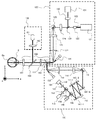
本実施形態の眼底撮像装置の光学概要図について、図1を用いて説明する。
本実施例で用いる眼底撮像装置は、第一の眼底撮像装置、第二の眼底撮像装置と、内部固視灯装置を有している。
<Overall configuration of device>
An optical schematic diagram of the fundus imaging apparatus of the present embodiment will be described with reference to FIG.
The fundus imaging apparatus used in this embodiment includes a first fundus imaging apparatus, a second fundus imaging apparatus, and an internal fixation lamp device.
第一の眼底撮像装置は、接眼レンズユニット100、SLO120により構成されている。レーザ光源121は、半導体レーザやSLD光源(Super Luminescent Diode)が好適に用いることができる。用いる波長は、眼底観察として被検者の眩しさの軽減と分解能維持のために、700nm〜1000nmの近赤外の波長域が好適に用いられる。本実施の形態においては、波長780nmの半導体レーザを用いる。レーザ光源121から出射されたレーザはファイバ122を介して、ファイバコリメータ123から平行なビーム(計測光)となって出射される。
The first fundus imaging apparatus includes an
出射されたビームは、レンズ124、SLOスキャナ(Y)125、リレーレンズ126、127を経由し、SLOスキャナ(X)128に導かれる。当該ビームは、更に、スキャンレンズ101と接眼レンズ102を通り、被検眼Eに入射される。ここで、本実施形態では、SLOスキャナ(X)(Y)128、125としてガルバノスキャナを用いている。
The emitted beam is guided to the SLO scanner (X) 128 via the
以後、本実施形態における座標は、眼軸方向をz、眼底画像に対し水平方向をx、垂直方向をyとする。本実施形態ではx方向が主走査方向でy方向が副走査方向となる。 Hereinafter, the coordinates in the present embodiment are z for the axial direction, x for the horizontal direction with respect to the fundus image, and y for the vertical direction. In the present embodiment, the x direction is the main scanning direction and the y direction is the sub scanning direction.
被検眼Eに入射したビームは、被検眼Eの眼底Eaに点状のビームとして照射される。このビームが、被検眼Eの眼底Eaで反射あるいは散乱され、同一光路をたどり、リングミラー129まで戻る。眼底Eaに照射されているビームが反射散乱した光のうち、瞳孔周辺部を通った光(反射光)が、リングミラー129によって反射され、レンズ130を経由しアバランシェ・フォトダイオード(以下、APDと記述する)131に受光される。
The beam incident on the eye E is irradiated on the fundus Ea of the eye E as a dotted beam. This beam is reflected or scattered by the fundus oculi Ea of the eye E to be examined, follows the same optical path, and returns to the
第二の眼底撮像装置は、前述した第一の眼底撮像装置と同様の構成からなる接眼レンズユニット100と、AO装置を有するAO−SLOユニット140とから構成されている。光源141は、波長840nmのSLD光源を用いている。本実施形態では眼底撮像と波面測定のための光源を共用しているが、それぞれを別光源とし、光路の途中で合波する構成としても良い。
The second fundus imaging apparatus includes an
光源141から出射された光は、ファイバ142を通ってファイバコリメータ143により、平行な測定光として照射される。照射された測定光はビームスプリッタ144を透過し、補償光学系に導光される。
Light emitted from the
該補償光学系は、ビームスプリッタ145、収差を測定する波面センサ146、波面補正デバイス148および、それらに導光するための反射ミラー147−1〜4から構成される。反射ミラー147−1〜4は、少なくとも被検眼Eの瞳と波面センサ146、波面補正デバイス148とが光学的に共役関係になるように設置されている。また、本実施形態では、波面補正デバイス148として液晶素子を用いた空間位相変調器を用いている。
The compensation optical system includes a
測定光は波面補正デバイス148に入射して反射し、反射ミラー147−3に出射する。同様に、被検眼Eの眼底Eaから帰ってきた光も波面補正デバイス148に入射した後、反射ミラー147−2に出射する。また、測定光は、AO−SLOスキャナ(X)149、AO−SLOスキャナ(Y)152によって2次元に走査される。本実施形態ではAO−SLOスキャナ(X)149として高速な共振スキャナ(主走査用のスキャナ)、AO−SLOスキャナ(Y)152としてガルバノスキャナ(副走査用のスキャナ)を用いている。
The measurement light is incident on the
AO−SLOスキャナ(X)、(Y)149、152で走査された測定光は、ビームスプリッタ104で反射し、スキャンレンズ101、接眼レンズ102を通り被検眼Eに入射する。被検眼Eに入射した測定光は、眼底Eaで反射あるいは散乱し、同一光路を通り、ビームスプリッタ145によって一部は波面センサ146に入る。波面センサ146はビームの波面を測定するもので、シャックハルトマンセンサを用いている。ビームスプリッタ145を透過した反射散乱光は、今度はビームスプリッタ144によって一部が反射され、ファイバコリメータ153、ファイバ154を通して、光電子増倍管であるPM(Photomultiplier Tube)から成る光強度センサ155に導光される。
Measurement light scanned by the AO-SLO scanners (X), (Y) 149, 152 is reflected by the
導光された光は光強度センサ155で電気信号に変換され、制御部(不図示)によって画像化の処理が行われる。そして制御部が、AO−SLOスキャナ(X)149である共振スキャナと、AO−SLOスキャナ152であるガルバノスキャナを微小角度回転させると、眼底Eaの撮像対象領域からの光強度情報が得られ、眼底画像として画像が構成されて、制御部の制御により表示装置(図2参照)に表示される。なお、微小角度とはSLO120のスキャン角度と比べた場合に小さいとの意味である。
The guided light is converted into an electrical signal by the
また、波面センサ146、波面補正デバイス148は制御部に接続されている。制御部は、波面センサ146の測定結果によって取得された波面を基に、収差のない波面へと補正するような変調量(補正量)を計算し、波面補正デバイス148にその変調を指令する。波面の測定と波面補正デバイス148への指示は繰り返し処理され、常に最適な波面となるようにフィードバック制御が行われる。その結果被検眼において発生した収差の除去或いは低減が実行される。本実施形態では波面補正デバイス148として画素数600×600の反射型液晶空間位相変調器を用いた。波面補正デバイス148の他の例としては、膜状のミラーとそのミラーを駆動する複数のアクチュエータから構成される可変形状ミラーがある。本例のような液晶空間位相変調器も可変形状ミラーも、反射面もしくは透過部において局所的に光の方向を変えることが可能で、透過もしくは反射する光の波面を変化させることが可能である。
The
内部固視灯160は、光源161、レンズ162で構成される。光源161として複数の発光ダイオード(LD)がマトリックス状に配置されたものを用いる。発光ダイオードの点灯位置は、制御部の制御により撮像したい部位に合わせて変更される。光源161からの光は、レンズ162を介し、ダイクロイックミラー103により被検眼Eに導かれる。光源161から出射される光は520nmで、制御部により所望のパターンが表示される。
The
<機能構成>
本実施形態の機能構成に関して、図2を用い説明する。各機能部材を制御する制御部(PC)200は表示装置212、CPU201、記録装置HDD202と、各装置の制御部である固視灯制御部203、SLO制御部210とAO−SLO制御部209から構成されている。CPU201からの指示の下、固視灯表示する表示装置204(図1の光源161に対応)は固視灯制御部203の制御により、SLO装置のX,Yスキャナ205(図1のSLOスキャナ125と128に対応)とSLO光源206(図1のレーザ光源121に対応)はSLO制御部210の制御により、AO−SLO装置のX,Yスキャナ208(図1のAO−SLOスキャナ149と152に対応)とAO−SLO光源207(図1の光源141に対応)はAO−SLO制御部209の制御により各装置が動作する。補償光学の構成要素である、波面センサ146および波面補正デバイス148もAO−SLO制御部209により制御される。
<Functional configuration>
The functional configuration of this embodiment will be described with reference to FIG. A control unit (PC) 200 that controls each functional member includes a
また、被検眼Eからの信号は、AO−SLOの受光部材PM214(図1の光強度センサ155に対応する)、SLOの受光部材APD215(図1のAPD131に対応する)を介して、得られる。得られた信号はCPU201で画像化され、表示装置212に表示される。
Further, a signal from the eye E is obtained via the light receiving member PM214 of AO-SLO (corresponding to the
<フロー>
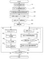
以上の装置を用い、第一の眼底装置SLO装置を追尾に用い、追尾結果をAO−SLO装置のスキャナおよび波面補正デバイスにフィードバックする事で所望位置のAO−SLO画像を安定して取得する。そのフローを図3に示す。なお、特に記載がない場合は、CPU201によって実行される処理である。
<Flow>
Using the above apparatus, the first fundus apparatus SLO apparatus is used for tracking, and the tracking result is fed back to the scanner and wavefront correction device of the AO-SLO apparatus, thereby stably acquiring an AO-SLO image at a desired position. The flow is shown in FIG. Unless otherwise specified, the processing is executed by the
先ず、第一の眼底撮像装置により、固視灯161を点灯して被検眼Eに提示した状態で、レーザ光源121からレーザを出力してAPD131で反射光を受光することでSLO眼底画像を取得する(ステップ301)。該第一の眼底撮像装置は、被検眼の眼底全体の眼底画像を撮像する手段として機能している。
First, with the first fundus imaging device, the SLO fundus image is obtained by outputting the laser from the
操作者の入力装置(不図示)からの指示に基づき、SLO画像内にAO−SLOの撮像範囲を決定する(ステップ302)。当該処理はCPU201において第一のビームであるAO−SLO光が照射される被検眼の第一の範囲を設定する第一の範囲設定手段として機能するモジュール領域により実行される。当該第一の範囲は予め撮像された眼底画像に基づいて設定される。設定されたAO−SLO光による撮像範囲を、CPU201のメモリに保存する(ステップ303)。
Based on an instruction from the operator's input device (not shown), an AO-SLO imaging range is determined in the SLO image (step 302). The processing is executed by the module area functioning as first range setting means for setting the first range of the eye to be inspected that is irradiated with the AO-SLO light that is the first beam in the
撮像された眼底画像から追尾の為のテンプレートを少なくとも1つ抽出する(処理A:ステップ304)。即ち、第一の範囲設定手段で設定された第一の範囲に基づいて、第二のビームである追尾用のSLO光が照射される被検眼の第二の範囲がテンプレートとして設定、抽出される。この第二の範囲の設定はCPU201において第二の範囲設定手段として機能するモジュール領域により実行される。抽出したテンプレートの周囲の一定範囲を追尾スキャン範囲とする(ステップ305)。
At least one tracking template is extracted from the captured fundus image (Process A: Step 304). That is, based on the first range set by the first range setting means, the second range of the eye to be examined that is irradiated with the tracking SLO light as the second beam is set and extracted as a template. . The setting of the second range is executed by the module area functioning as second range setting means in the
眼底画像の撮像を開始し(ステップ306)、AO−SLO装置とSLO装置を動作させる。AO−SLO装置は、x、yスキャナ208を駆動させステップ302で決定された撮像範囲をスキャンし(ステップ307)、AO−SLO信号を取得し、信号を画像化する(ステップ309)。即ち、第一のビームたるAO−SLO光による戻り光に基づいて、被検眼の第一の画像であるAO−SLOの画像を生成する。当該画像生成は、CPU201において第一の生成手段として機能するモジュール領域により実行される。その後、該AO−SLOの画像をHDD202に保存する(ステップ310)。
Imaging of the fundus image is started (step 306), and the AO-SLO device and the SLO device are operated. The AO-SLO device drives the x and
本実施例では、ステップ308で収差補正処理を行っている。収差補正処理は、波面センサからの信号をもとに収差の測定を行い、その収差測定結果に応じて波面補正デバイスを駆動することによって収差を補正する。
In this embodiment, the aberration correction process is performed in
本実施例では、測定した波面をZernike関数にモデル化して各次数にかかる係数を算出し、その係数を元に波面補正デバイス148の変調量を算出する。変調量の算出においては、波面補正デバイス148がZernike各次数の形状を形成するための基準変調量を元に、測定された全てのZernike次数の係数に関して基準変調量を乗算し、さらにそれらをすべて積算することによって最終的な変調量を得る。一般的に眼用に補償光学を構築する場合には、測定した波面をZernike関数の1次から6次程度の次数の範囲をモデル化のために使用する。例えば、Zernikeの1次は水平垂直の進行方向を表し、2次はフォーカスや乱視を表す。
In the present embodiment, the measured wavefront is modeled as a Zernike function to calculate a coefficient for each order, and the modulation amount of the
ステップ308は上記処理をある程度繰り返して、収差量が任意の閾値以下に低下するまで続ける。また、撮影と全く同期せずに収差補正の処理を行う構成も可能である。
同時に、SLO装置のX,Yスキャナ205を用い、ステップ305で決定した範囲を走査させ(ステップ311)、SLO画像を取得する。即ち、前述した第二のビームの被検眼からの戻り光に基づいて、追尾のための被検眼の第二の画像が生成される。当該画像の生成は、CPU201において第二の生成手段として機能するモジュール領域により実行される。
Step 308 repeats the above process to some extent and continues until the aberration amount falls below an arbitrary threshold value. In addition, a configuration in which aberration correction processing is performed without any synchronization with photographing is possible.
At the same time, the range determined in
取得したSLO画像において、テンプレートマッチングを行い、テンプレートの座標とマッチングした座標を比較する事で、眼球の動き(移動量と向き)を算出する(処理B:ステップ312)。この算出処理は、CPU201において第二の画像に基づいて被検眼の動きを検出する検出手段として機能するモジュール領域により実行される。なお、当該検出手段は、テンプレートとして抽出された領域画像と、この段階で得られている新たに生成された第二の画像とを比較することで動きの検出をなしており、当該比較を行う被検眼の動きを検出する手段も包含している。
In the acquired SLO image, template matching is performed, and the movement of the eyeball (movement amount and direction) is calculated by comparing the coordinate with the coordinate of the template (Process B: Step 312). This calculation process is executed by the module area that functions as a detection unit that detects the movement of the eye to be examined based on the second image in the
次に、検出された被検眼の動き量である移動量と、移動量における規定値(m)μmとの比較を行う(ステップ313)。該規定値(m)は当該ステップ313の比較工程にて動き量と比較される所定の閾値に対応する。また、当該比較工程はCPU201において比較手段として機能するモジュール領域により実行される。ここで、移動量が規定値(m)を超えていない場合は、ステップ314に進み、超えている場合はAO−SLO装置の撮影範囲補正に反映される(ステップ313のYes)。この撮影範囲の補正は検出された被検眼の動きに基づいて行われ、当該処理はCPU201において第一の範囲を補正する補正手段として機能するモジュール領域により実行される。即ち、ここで述べる規定値(m)は、眼球の動きに関して追尾を実行して撮像範囲を調整する必要があるか否かを判定するための基準値として設定される。また、該規定値(m)は標準の値が予め定められているが、被検眼ごとに設定する、記録装置HDD202に格納されたデータより読み出す等、種々態様により被検眼に応じて設定しても良い。
Next, a comparison is made between the detected amount of movement, which is the amount of movement of the eye to be examined, and a specified value (m) μm in the amount of movement (step 313). The prescribed value (m) corresponds to a predetermined threshold value that is compared with the amount of movement in the comparison step of
ステップ314(処理C)で行なわれる当該撮影範囲の補正、即ち撮影範囲の修正は、走査手段たるスキャナの走査範囲の補正および収差補正デバイスによるチルト補正により行われる。なお、本実施形態ではビームの照射範囲たる走査範囲の補正はビームの照射方向の変更により好適に行われるが、本発明は当該変更様式に限定されるものではない。
AO−SLOの撮像が終了したら、処理を終了させる(ステップ315のYes)。
The correction of the imaging range, that is, the correction of the imaging range performed in step 314 (Process C) is performed by correcting the scanning range of the scanner as a scanning unit and tilt correction by the aberration correction device. In this embodiment, the correction of the scanning range, which is the beam irradiation range, is preferably performed by changing the beam irradiation direction, but the present invention is not limited to this change mode.
When the AO-SLO imaging is completed, the process is terminated (Yes in step 315).
ステップ304の処理Aについて、図4(a)を用いて、説明する。SLO画像とSLO撮像禁止エリアを読みだす(ステップ401)。禁止エリア外のSLO画像からテンプレートを抽出する(ステップ402)。テンプレートの座標と画像をメモリに保存する(ステップ403)。 The processing A of Step 3 04, using 4 (a), will be described. The SLO image and the SLO imaging prohibition area are read out (step 401). A template is extracted from the SLO image outside the prohibited area (step 402). The template coordinates and image are stored in the memory (step 403).
処理Bについて、図4(b)を用いて、説明する。テンプレート画像と座標をメモリから読みだす(ステップ410)。読みだしたテンプレート画像と新規に取得したSLO画像を用い、テンプレートマッチングを行う(ステップ411)。マッチングしたマッチング画像と座標をメモリに保存する(ステップ412)。テンプレート座標とマッチング座標から眼底の動き(移動量と方向)を算出する(ステップ413)。 Process B will be described with reference to FIG. The template image and coordinates are read from the memory (step 410). Template matching is performed using the read template image and the newly acquired SLO image (step 411). The matched matching image and coordinates are stored in the memory (step 412). The movement (movement amount and direction) of the fundus is calculated from the template coordinates and the matching coordinates (step 413).
処理Cについて、図4(c)を用いて説明する。ステップ312で算出した眼球の移動量を読みだす(ステップ414)。本例では、眼底の移動量が一定範囲内の場合には収差補正デバイスで撮影位置を調整し、一定の範囲を超える場合にはビーム走査手段の走査範囲を調整する。より詳細には、ステップ415で眼の移動量が一定の閾値(n)μmを超えているかを判断し、(n)μm超えている場合にはステップ416に進みスキャナの走査中心を被検眼の移動量を基に調整して、ビームの照射範囲の調整をする。当該ステップ415の操作も、本発明における比較工程の一態様として把握される。眼移動量が閾値(n)を超えていない場合には、ステップ417において収差補正デバイスに対してチルトを指示する。即ち、ここで述べた閾値(n)は、被検眼の追尾操作に関して、ガルバノスキャナ等を動作させて撮像範囲を変化させて追尾を行ったほうが好適であるか、或いは収差補正デバイスによってチルトを与えることによって追尾を行ったほうが好適であるかを判断する基準値として設定される。更に当該閾値(n)は、比較工程における所定の閾値の一態様に対応する。ここで、収差補正デバイスに対してチルトを指示する場合には、即座に収差補正デバイスを駆動しても良いし、ステップ308のAO処理の際に波面センサが測定した波面に眼移動量に対応したZernike1次の収差を加算したうえで補正デバイスを駆動するように制御しても良い。以上のステップ415は、ステップ313での比較結果に応じて、ビームの照射方向の変更による照射範囲の変更と、収差補正手段によるビームの照射範囲の変更との少なくとも何れを実行するかを決定する決定工程に対応し、CPU201において決定手段として機能するモジュール領域により実行される。また、ステップ416及び417はビームの照射範囲を調整する調整工程に対応し、CPU201において調整手段として機能するモジュール領域により実行される。眼の移動に対して以上の処理を行ったら、ステップ418で撮影範囲をスキャンするように制御する。
Process C will be described with reference to FIG. The movement amount of the eyeball calculated in
また、処理Cの他例について図6を用いて説明する。ステップ312において算出された眼球の移動量の履歴を保存しておき、ステップ601でその履歴を読みだす。読みだした移動量の履歴から眼の動きを周波数分解する(ステップ602)。より詳細には、検出された位置情報をフーリエ変換等で周波数分解して眼の動きの成分を高周波成分と低周波成分とに分離して取得する。なお、この分離に際しては、特定の閾値より大きい値からなる部分を高周波成分とし、小さい値からなる部分を低周波成分としているが、この特定の閾値は装置構成、被検者等に応じて変更されることが好ましい。本実施形態では初期値として、この特定の閾値を10Hzとしている。一般的に眼の動きは低周波で動き即ち振幅の大きいドリフトと呼ばれるものと、周波数が高く振幅の小さいトレモアと呼ばれるもの、突発的に大きく移動するサッケードと呼ばれるものによって大部分が占められている。そこで、微小高周波の動きと大低周波の動きを前述した様式にて分解し、それぞれ異なる装置で補正する。ステップ603で高周波成分を補正するように、収差補正デバイスにチルトの指示を与える。本例においても即時に補正を行っても良いし、AOの制御のタイミングで補正するように制御しても良い。また、一般的に収差補正デバイスは大きな動きは不可能であるので、さらに動きの量を判断して、可能な範囲に限定して収差補正デバイスに指示して、残りは別のデバイスを制御することによって補正する方法も可能である。ステップ604で低周波成分を補正するようにスキャナ走査の中心位置を設定する。
Another example of the process C will be described with reference to FIG. A history of the movement amount of the eyeball calculated in
このようにAO−SLOの撮像が行われている間も追尾を行う事で、所望の位置の画像を取得する事が出来る。これにより、画像の重ね合せによる視細胞解析、血管をモニタする事による血流解析が可能となる。撮像中、表示装置212には図5の様な画像が表示される。初期に取得したSLO画像501上に最新の追尾画像505と最新のAO−SLOの撮像画像507と固視灯位置506を同一画面に表示し、眼球の移動量をグラフ化した504、波面センサ情報503、AO−SLO画像502、が表示装置に表示される。本実施例では、最新の情報の表示方法として、初期に取得した広画角を撮像したSLO画像501と固視灯表示506を眼球の動きに合わせて動かして表示している。表示方法として、広画角のSLO画像501上で、最新の追尾画像505とAO−SLO画像が動く表示方法でも良い。
In this way, an image at a desired position can be acquired by performing tracking while AO-SLO is being imaged. Thereby, photoreceptor analysis by superimposing images and blood flow analysis by monitoring blood vessels are possible. During imaging, an image as shown in FIG. 5 is displayed on the
被検眼の固視微動は、上述したようにトレモア、ドリフト、及びサッケードの各成分の合成からなる。このため、従来のように単一の光軸調整手段であるガルバノスキャナで該固視微動の影響を受けた画像を補正しようとしても追従精度上難点がある。これに対して例えば他の光軸調整手段によって追従精度を高めることも考えられるが、例えば共振スキャナについては固定位置に制御することが難しくトラッキングに用いることができない。これに対して収差補正デバイスはもともとチルト成分を補正することから光軸調整機能も有し、微小な光軸調整が可能である。本発明では従来共振スキャナを用いてスキャンを行っていた方向についてのトラッキングをこの収差補正デバイスによって行い、複数の方向でのトラッキングの追従精度を高めている。 As described above, the fixation fine movement of the eye to be inspected is composed of a combination of tremor, drift, and saccade components. For this reason, there is a difficulty in tracking accuracy even if an image affected by the fixation micromotion is corrected by a galvano scanner which is a single optical axis adjusting means as in the prior art. On the other hand, for example, it is conceivable to increase the tracking accuracy by using another optical axis adjusting means. However, it is difficult to control the resonance scanner to a fixed position, for example, and it cannot be used for tracking. On the other hand, since the aberration correction device originally corrects the tilt component, it also has an optical axis adjustment function, and fine optical axis adjustment is possible. In the present invention, tracking in the direction in which scanning is conventionally performed using a resonance scanner is performed by this aberration correction device, and tracking tracking accuracy in a plurality of directions is improved.
以上のように、複数のデバイスを撮影位置調整に用いることにより、分解能が高いAO−SLOにおいても精度の高い追尾が可能となり、高画質なAO−SLO画像を得る事が出来る。即ち、本発明によれば、補償光学の波面補正装置である収差補正デバイスを撮影位置調整手段にも用いることにより、高精度な眼球追尾を実現し、高画質な眼底像の撮像が可能となる。 As described above, by using a plurality of devices for adjusting the photographing position, it is possible to perform tracking with high accuracy even in AO-SLO with high resolution, and a high-quality AO-SLO image can be obtained. In other words, according to the present invention, by using an aberration correction device, which is a wavefront correction device for adaptive optics, as a photographing position adjusting means, high-accuracy eye tracking can be realized and high-quality fundus images can be captured. .
[第二の実施形態]
以下、本発明の第二の実施形態について説明する。
本実施形態では、AO−SLO画像から眼底位置を算出し、眼底位置データをAO−SLOの撮影範囲制御に反映し、安定した高画質なAO−SLO画像を取得した例について述べる。
<装置の全体構成>
本実施形態の眼底撮像装置の光学概要図について、図7を用いて説明する。
AO−SLOと内部固視灯装置に関しては、第一の実施形態と同様の構成の為、説明は割愛する。
[Second Embodiment]
Hereinafter, a second embodiment of the present invention will be described.
In the present embodiment, an example will be described in which the fundus position is calculated from the AO-SLO image, the fundus position data is reflected in the imaging range control of the AO-SLO, and a stable high-quality AO-SLO image is acquired.
<Overall configuration of device>
An optical schematic diagram of the fundus imaging apparatus of the present embodiment will be described with reference to FIG.
Since the AO-SLO and the internal fixation lamp device have the same configuration as that of the first embodiment, description thereof is omitted.
ただし、本例においては収差補正用のための波面測定光を入射する。レーザ光源170は半導体レーザやSLD光源(Super Luminescent Diode)が好適に用いることができる。用いる波長は、AO−SLOとなるべく近い700nm〜1000nmの近赤外の波長域が好適に用いられる。本実施の形態においては、波長760nmのSLDを用いた。レーザ光源170から出射されたレーザはファイバ171を介して、ファイバコリメータ172から平行なビーム(計測光)となって出射される。出射されたビームは、AO−SLOの測定光と同様にビームスプリッタ104、スキャンレンズ101と接眼レンズ102を通り、被検眼Eに入射される。ビームスプリッタ104は例えば、波面測定光は50%透過し、AO−SLO測定光は100%反射するように構成すれば、AO−SLOの信号光を最小限の損失で受光することが可能となる。
However, in this example, wavefront measuring light for aberration correction is incident. As the
波面センサであるシャックハルトマンセンサ146の直前のビームスプリッタ145は、波面測定光を100%反射し、AO−SLO測定光を100%透過するようにすれば、波面測定および眼底撮影共に高い効率で測定する事が可能となる。
If the
眼底Eaから反射散乱した波面測定光は、AO−SLOと同様の経路でビームスプリッタ145まで到達し、波面センサ146に入射する。波面センサ146は入射した波面測定光から収差を測定し、その収差を基にAO制御をおこなう。
The wavefront measurement light reflected and scattered from the fundus oculi Ea reaches the
<機能構成>
本実施形態の機能構成に関して、図8を用い説明する。各機能部材を制御する制御部(PC)200は表示装置212、CPU201、記録装置HDD202と、各装置の制御部である固視灯制御部203、AO−SLO制御部209から構成されている。CPU201からの指示の下、固視灯表示する表示装置204(図7の光源161に対応)は固視灯制御部203の制御により、AO−SLO装置のX,Yスキャナ208(図7のAO−SLOスキャナ149と152に対応)とAO−SLO光源207(図7の光源141に対応)と波面測定光源801(図7の光源170に対応)はAO−SLO制御部209の制御により各装置が動作する。補償光学の構成要素である、波面センサ146および波面補正デバイス148もAO−SLO制御部209により制御される。
<Functional configuration>
The functional configuration of this embodiment will be described with reference to FIG. A control unit (PC) 200 that controls each functional member includes a
また、被検眼Eからの信号は、AO−SLOの受光部材PM214(図7の光強度センサ155に対応する)を介して得られる。得られた信号はCPU201で画像化され、表示装置212に表示される。
Further, a signal from the eye E is obtained through the light receiving member PM214 of AO-SLO (corresponding to the
<フロー>
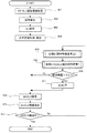
以上の装置を用い、AO−SLO画像から位置情報を算出し、その位置変化をAO−SLO装置のスキャナおよび波面補正デバイスにフィードバックする事で所望位置のAO−SLO画像を安定して取得する。そのフローを図9に示す。なお、特に記載がない場合は、CPU201によって実行される処理である。
<Flow>
Using the above apparatus, position information is calculated from the AO-SLO image, and the change in position is fed back to the scanner and the wavefront correction device of the AO-SLO apparatus, thereby stably acquiring the AO-SLO image at the desired position. The flow is shown in FIG. Unless otherwise specified, the processing is executed by the
先ず、操作者の入力装置(不図示)からの指示に基づき、SLO画像内にAO−SLOの撮像範囲を決定する(ステップ901)。実際には、固視灯161の点灯位置を変更することで撮影位置を調整する。
First, an AO-SLO imaging range is determined in an SLO image based on an operator's instruction from an input device (not shown) (step 901). Actually, the shooting position is adjusted by changing the lighting position of the
ステップ902で撮影を開始する。このステップで波面測定光が眼底に照射される。ステップ903で一連のAO処理が実行される。具体的には、波面センサからの信号をもとに波面補正デバイスを駆動することによって収差を補正する。当該ステップは上記処理をある程度繰り返して、収差量が任意の閾値以下に低下するまで続ける。一定閾値まで低下した段階で収差補正デバイスの状態を維持しても良いし、AO−SLO撮影中のAO処理を継続する構成も可能である。
In
ステップ904で基準となるAO−SLO画像を取得する。取得した画像は基準画像として保存される。この基準画像全体がテンプレートとして利用される。
In
AO−SLO装置は、X、Yスキャナ208を駆動させステップ901で決定された撮像範囲をスキャンし、AO−SLO信号を取得して信号を画像化する(ステップ905)。即ち、第一のビームたるAO−SLO光による戻り光に基づいて、被検眼の第一の画像であるAO−SLOの画像を生成する。その後、該AO−SLOの画像をHDD202に保存する(ステップ906)。
The AO-SLO device drives the X and
AO−SLO画像を更に得ようとする場合、取得したAO−SLO画像において、テンプレートマッチングを行い、テンプレートの座標とマッチングした座標を比較する事で、眼球の動き(移動量と向き)を算出する(処理B:ステップ908)。なお、当該検出手段は、テンプレートとして保存されている基準画像と、この段階で得られている新たに生成された画像とを比較することで動きの検出をなしており、当該比較を行う被検眼の動きを検出する手段も包含している。処理Bであるステップ908の動作は、第一の実施形態の処理Bの動作と同様である。
When further obtaining an AO-SLO image, template matching is performed on the acquired AO-SLO image, and the movement of the eyeball (movement amount and direction) is calculated by comparing the coordinate of the template with the coordinate of the template. (Process B: Step 908). The detection means detects a movement by comparing a reference image stored as a template with a newly generated image obtained at this stage, and the eye to be examined is subjected to the comparison. It also includes means for detecting the movement of. The operation of
また、一般的にAO−SLO画像は撮影範囲が小さいので大きく目が動いてしまうと撮影画像が基準画像の撮影範囲外に移動してしまう可能性があるので、顔位置や瞳位置確認用のモニタ機能等で眼の大きな動きを測定しても良い。さらに、波面センサ146を用いても、瞳位置の平行移動および回転が検出可能であるので、眼底画像と併せて波面センサの測定値も位置情報算出に用いることにより、精度の高い位置検出が可能となる。
In general, an AO-SLO image has a small shooting range, so if the eye moves greatly, the shot image may move outside the shooting range of the reference image. A large eye movement may be measured by a monitor function or the like. Furthermore, since the translation and rotation of the pupil position can be detected using the
ここで算出された移動量はAO−SLO装置の撮影範囲補正に反映される。当該補正は、走査手段たるスキャナの走査範囲の補正および収差補正デバイスにより行われる(処理C:ステップ909)。処理Cであるステップ909の動作は、第一の実施形態の処理Cの動作と同様である。
The movement amount calculated here is reflected in the photographing range correction of the AO-SLO device. The correction is performed by the correction of the scanning range and the aberration correction device of the scanner as the scanning means (Process C: Step 909). The operation of
ここで、眼底の移動量が任意の閾値(o)μm以上で合った場合(ステップ910)には、収差の状態が大きく変化していると考えられるので、ステップ911に進みAO処理が再度実行される。AO処理はステップ903と同様である。ただし、AO−SLO撮影中もAO処理を行う構成であれば、このステップは必要ない。即ち、ここで述べる任意の閾値(o)μmは、撮像範囲が移ることによって収差が変化して好適な画像が得られるか否かを判定するための閾値であって、当該閾値以下の移動量である場合には得られる画像は診断に使用可能な眼底画像が得られると認められることとなる。
Here, when the amount of movement of the fundus matches with an arbitrary threshold (o) μm or more (step 910), it is considered that the aberration state has changed greatly, so the process proceeds to step 911 and the AO process is executed again. Is done. The AO process is the same as
その後ステップ905に進み、AO−SLO撮像が継続される。
AO−SLOの撮像が終了したら、処理を終了させる(ステップ907のYes)。
Thereafter, the process proceeds to step 905, and AO-SLO imaging is continued.
When the AO-SLO imaging is completed, the process is terminated (Yes in step 907).
以上のように、AO−SLOと別の眼底撮像手段を用いなくても撮影位置の追尾が可能となる。複数のデバイスを撮影位置調整に用いることにより、分解能が高いAO−SLOにおいても精度の高い追尾が可能となり、高画質なAO−SLO画像を得る事が出来る。 As described above, the shooting position can be tracked without using a fundus imaging unit different from AO-SLO. By using a plurality of devices for adjusting the photographing position, it becomes possible to perform tracking with high accuracy even in AO-SLO with high resolution, and high-quality AO-SLO images can be obtained.
(その他の実施形態)
また、本発明は、以下の処理を実行することによっても実現される。即ち、上述した実施形態の機能を実現するソフトウェア(プログラム)を、ネットワーク又は各種記憶媒体を介してシステム或いは装置に供給し、そのシステム或いは装置のコンピュータ(またはCPUやMPU等)がプログラムを読み出して実行する処理である。
(Other embodiments)
The present invention can also be realized by executing the following processing. That is, software (program) that realizes the functions of the above-described embodiments is supplied to a system or apparatus via a network or various storage media, and a computer (or CPU, MPU, or the like) of the system or apparatus reads the program. It is a process to be executed.
更に、本件は上記の実施形態に限定されるものではなく、本発明の趣旨を逸脱しない範囲内において、種々の変形、変更して実施することができる。例えば、上記の実施形態では、被測定物が眼の場合について述べているが、眼以外の皮膚や臓器等の被測定物に本発明を適用することも可能である。この場合、本発明は眼科装置以外の、例えば内視鏡等の医療機器としての態様を有する。従って、本発明は眼科装置に例示される検査装置として把握され、被検眼は被検査物の一態様として把握されることが望ましい。 Furthermore, the present invention is not limited to the above-described embodiment, and various modifications and changes can be made without departing from the spirit of the present invention. For example, in the above-described embodiment, the case where the object to be measured is the eye has been described, but the present invention can also be applied to the object to be measured such as skin or organ other than the eye. In this case, the present invention has an aspect as a medical device such as an endoscope other than the ophthalmologic apparatus. Therefore, it is desirable that the present invention is grasped as an inspection apparatus exemplified by an ophthalmologic apparatus, and the eye to be examined is grasped as one aspect of the object to be examined.
E:被検眼
120:SLO装置
140:AO−SLO装置
160:内部固視灯装置
501:眼底画像
E: Eye to be examined 120: SLO device 140: AO-SLO device 160: Internal fixation lamp device 501: Fundus image
Claims (15)
前記被検査物で発生する収差を測定する収差測定手段と、An aberration measuring means for measuring an aberration generated in the inspection object;
前記測定した収差に応じて前記収差の補正を行う収差補正手段と、Aberration correction means for correcting the aberration according to the measured aberration;
前記被検査物の動き量を検出する検出手段と、Detecting means for detecting the amount of movement of the inspection object;
前記検出された動き量と所定の閾値とを比較する比較手段と、Comparing means for comparing the detected amount of motion with a predetermined threshold;
前記走査手段による前記ビームの照射位置の変更と、前記収差補正手段による前記ビームの照射位置の変更との少なくとも何れを実行するかを決定する決定手段と、Determining means for determining at least which of the change of the irradiation position of the beam by the scanning means and the change of the irradiation position of the beam by the aberration correction means;
前記比較手段による比較結果に基づいて、前記決定手段による決定に従って、前記ビームの照射位置を制御する制御手段と、を備えることを特徴とする撮像装置。An imaging apparatus comprising: a control unit that controls an irradiation position of the beam according to a determination by the determination unit based on a comparison result by the comparison unit.
前記決定手段は、前記振幅が大きく周波数が低い変化に対しては前記走査手段による前記ビームの照射位置の変更を実行することに決定し、前記振幅が小さく周波数が高い変化に対しては前記収差補正手段による前記ビームの照射位置の変更を実行することに決定する、ことを特徴とする請求項6に記載の撮像装置。 The detection means decomposes the detected amount of movement into a change with a large amplitude and a low frequency and a change with a small amplitude and a high frequency,
Said determining means, said relative amplitude is large lower frequency changes decides to implement a change in irradiation position of the beam by the scanning means, the aberration with respect to the amplitude is small higher frequency change The imaging apparatus according to claim 6 , wherein the correction unit determines to change the irradiation position of the beam.
Priority Applications (5)
| Application Number | Priority Date | Filing Date | Title |
|---|---|---|---|
| JP2013086790A JP6224908B2 (en) | 2013-04-17 | 2013-04-17 | Imaging device |
| US14/251,820 US9757029B2 (en) | 2013-04-17 | 2014-04-14 | Fundus imaging apparatus and imaging method |
| GB1406876.1A GB2516146B (en) | 2013-04-17 | 2014-04-16 | Fundus imaging apparatus and imaging method |
| DE201410207328 DE102014207328A1 (en) | 2013-04-17 | 2014-04-16 | Fundus imaging device and imaging method |
| US15/662,404 US10939817B2 (en) | 2013-04-17 | 2017-07-28 | Fundus imaging apparatus and imaging method |
Applications Claiming Priority (1)
| Application Number | Priority Date | Filing Date | Title |
|---|---|---|---|
| JP2013086790A JP6224908B2 (en) | 2013-04-17 | 2013-04-17 | Imaging device |
Publications (3)
| Publication Number | Publication Date |
|---|---|
| JP2014209980A JP2014209980A (en) | 2014-11-13 |
| JP2014209980A5 JP2014209980A5 (en) | 2016-06-09 |
| JP6224908B2 true JP6224908B2 (en) | 2017-11-01 |
Family
ID=50845122
Family Applications (1)
| Application Number | Title | Priority Date | Filing Date |
|---|---|---|---|
| JP2013086790A Active JP6224908B2 (en) | 2013-04-17 | 2013-04-17 | Imaging device |
Country Status (4)
| Country | Link |
|---|---|
| US (2) | US9757029B2 (en) |
| JP (1) | JP6224908B2 (en) |
| DE (1) | DE102014207328A1 (en) |
| GB (1) | GB2516146B (en) |
Families Citing this family (8)
| Publication number | Priority date | Publication date | Assignee | Title |
|---|---|---|---|---|
| JP6224908B2 (en) * | 2013-04-17 | 2017-11-01 | キヤノン株式会社 | Imaging device |
| JP6322042B2 (en) | 2014-04-28 | 2018-05-09 | キヤノン株式会社 | Ophthalmic photographing apparatus, control method thereof, and program |
| JP6552200B2 (en) | 2015-01-09 | 2019-07-31 | キヤノン株式会社 | Optical tomographic imaging apparatus, control method thereof, and program |
| JP6701587B2 (en) | 2015-03-31 | 2020-05-27 | 国立大学法人東北大学 | Image display device, processing method, and program |
| JP6590513B2 (en) * | 2015-04-30 | 2019-10-16 | キヤノン株式会社 | Information processing apparatus, operating method thereof, and computer program |
| US9867538B2 (en) * | 2016-03-21 | 2018-01-16 | Canon Kabushiki Kaisha | Method for robust eye tracking and ophthalmologic apparatus therefor |
| CN107157439B (en) * | 2017-05-31 | 2019-01-18 | 温州医科大学 | A kind of confocal laser scanning fundus imaging and optical projection system |
| CN111568368B (en) * | 2020-05-25 | 2023-06-06 | 歌尔科技有限公司 | Eyeball movement abnormality detection method, device and equipment |
Family Cites Families (48)
| Publication number | Priority date | Publication date | Assignee | Title |
|---|---|---|---|---|
| US6271914B1 (en) * | 1996-11-25 | 2001-08-07 | Autonomous Technologies Corporation | Objective measurement and correction of optical systems using wavefront analysis |
| US6199986B1 (en) * | 1999-10-21 | 2001-03-13 | University Of Rochester | Rapid, automatic measurement of the eye's wave aberration |
| US20060238710A1 (en) * | 1999-12-03 | 2006-10-26 | Manfred Dick | Method for determining vision defects and for collecting data for correcting vision defects of the eye by interaction of a patient with an examiner and apparatus therefor |
| DE19958436B4 (en) * | 1999-12-03 | 2014-07-17 | Carl Zeiss Meditec Ag | Apparatus and method for active, physiologically evaluated, comprehensive correction of the aberrations of the human eye |
| US7284862B1 (en) * | 2003-11-13 | 2007-10-23 | Md Lasers & Instruments, Inc. | Ophthalmic adaptive-optics device with a fast eye tracker and a slow deformable mirror |
| JP4510534B2 (en) * | 2004-06-22 | 2010-07-28 | 株式会社トプコン | Optical characteristic measuring device and fundus image observation device |
| EP1858402B1 (en) | 2005-01-21 | 2017-11-29 | Massachusetts Institute Of Technology | Methods and apparatus for optical coherence tomography scanning |
| EP1928294B1 (en) * | 2005-08-18 | 2010-09-08 | Imagine Eyes | Method and system for correcting aberrations of the eye for an ophthalmic instrument |
| US7742213B2 (en) * | 2005-12-29 | 2010-06-22 | Rensselaer Polytechnic Institute | Adaptive-scanning optical microscope |
| US7758189B2 (en) | 2006-04-24 | 2010-07-20 | Physical Sciences, Inc. | Stabilized retinal imaging with adaptive optics |
| JP5038703B2 (en) * | 2006-12-22 | 2012-10-03 | 株式会社トプコン | Ophthalmic equipment |
| JP5448353B2 (en) | 2007-05-02 | 2014-03-19 | キヤノン株式会社 | Image forming method using optical coherence tomography and optical coherence tomography apparatus |
| JP5306041B2 (en) | 2008-05-08 | 2013-10-02 | キヤノン株式会社 | Imaging apparatus and method thereof |
| JP5495506B2 (en) | 2008-05-13 | 2014-05-21 | キヤノン株式会社 | Laser apparatus and optical tomographic imaging apparatus |
| JP5478840B2 (en) | 2008-05-19 | 2014-04-23 | キヤノン株式会社 | Optical tomographic imaging apparatus and control method for optical tomographic imaging apparatus |
| JP5437755B2 (en) | 2009-04-15 | 2014-03-12 | 株式会社トプコン | Fundus observation device |
| JP5259484B2 (en) * | 2009-04-30 | 2013-08-07 | 株式会社ニデック | Fundus photographing device |
| JP5511323B2 (en) | 2009-11-17 | 2014-06-04 | キヤノン株式会社 | Compensating optical device, compensating optical method, imaging device, and imaging method |
| JP5836564B2 (en) | 2010-03-12 | 2015-12-24 | キヤノン株式会社 | Ophthalmic imaging apparatus, ophthalmic imaging method, and program thereof |
| US8998412B2 (en) | 2010-03-12 | 2015-04-07 | Canon Kabushiki Kaisha | Ophthalmologic apparatus and control method for the same |
| JP5818409B2 (en) | 2010-06-17 | 2015-11-18 | キヤノン株式会社 | Fundus imaging apparatus and control method thereof |
| JP5820154B2 (en) | 2010-07-05 | 2015-11-24 | キヤノン株式会社 | Ophthalmic apparatus, ophthalmic system, and storage medium |
| JP5539089B2 (en) | 2010-07-23 | 2014-07-02 | キヤノン株式会社 | Ophthalmic apparatus, control method and program for ophthalmic apparatus |
| JP5879830B2 (en) * | 2011-09-02 | 2016-03-08 | 株式会社ニデック | Fundus imaging device with wavefront compensation |
| JP5635898B2 (en) | 2010-12-17 | 2014-12-03 | キヤノン株式会社 | Fundus imaging apparatus and control method thereof |
| JP5731815B2 (en) | 2010-12-20 | 2015-06-10 | キヤノン株式会社 | Imaging method, imaging apparatus, and program |
| JP2012161382A (en) * | 2011-02-03 | 2012-08-30 | Nidek Co Ltd | Ophthalmological instrument |
| JP5917004B2 (en) | 2011-03-10 | 2016-05-11 | キヤノン株式会社 | IMAGING DEVICE AND IMAGING DEVICE CONTROL METHOD |
| JP5721478B2 (en) | 2011-03-10 | 2015-05-20 | キヤノン株式会社 | IMAGING DEVICE AND IMAGING DEVICE CONTROL METHOD |
| US9161690B2 (en) | 2011-03-10 | 2015-10-20 | Canon Kabushiki Kaisha | Ophthalmologic apparatus and control method of the same |
| JP5901124B2 (en) | 2011-03-10 | 2016-04-06 | キヤノン株式会社 | Imaging apparatus and control method thereof |
| US8950863B2 (en) | 2011-03-10 | 2015-02-10 | Canon Kabushiki Kaisha | Image photographing apparatus and image photographing method |
| US9033510B2 (en) * | 2011-03-30 | 2015-05-19 | Carl Zeiss Meditec, Inc. | Systems and methods for efficiently obtaining measurements of the human eye using tracking |
| JP5845608B2 (en) * | 2011-03-31 | 2016-01-20 | 株式会社ニデック | Ophthalmic imaging equipment |
| JP5850637B2 (en) * | 2011-04-27 | 2016-02-03 | キヤノン株式会社 | Fundus imaging apparatus, fundus imaging apparatus control method, and program |
| JP5913999B2 (en) | 2012-01-16 | 2016-05-11 | キヤノン株式会社 | Ophthalmic imaging apparatus and control method thereof |
| JP5997450B2 (en) | 2012-02-08 | 2016-09-28 | キヤノン株式会社 | Aberration correction method and aberration correction apparatus |
| JP6101048B2 (en) * | 2012-02-20 | 2017-03-22 | キヤノン株式会社 | Image processing apparatus and image processing method |
| JP5997457B2 (en) | 2012-02-21 | 2016-09-28 | キヤノン株式会社 | IMAGING DEVICE AND IMAGING DEVICE CONTROL METHOD |
| JP5955020B2 (en) | 2012-02-21 | 2016-07-20 | キヤノン株式会社 | Fundus imaging apparatus and method |
| JP6025349B2 (en) | 2012-03-08 | 2016-11-16 | キヤノン株式会社 | Image processing apparatus, optical coherence tomography apparatus, image processing method, and optical coherence tomography method |
| US9282887B2 (en) * | 2012-03-21 | 2016-03-15 | Utsunomiya University | Three-dimensional retina image generator |
| JP6021394B2 (en) | 2012-04-06 | 2016-11-09 | キヤノン株式会社 | Imaging method and imaging apparatus |
| EP2713195B1 (en) * | 2012-09-28 | 2017-04-12 | Universität Heidelberg | High resolution microscopy by means of structured illumination at large working distances |
| EP2712542B1 (en) * | 2012-09-28 | 2017-04-12 | Ruprecht-Karls-Universität Heidelberg | Structured illumination ophthalmoscope |
| JP6184114B2 (en) | 2013-01-31 | 2017-08-23 | キヤノン株式会社 | Optical coherence tomography apparatus and control method thereof |
| JP6460618B2 (en) | 2013-01-31 | 2019-01-30 | キヤノン株式会社 | Optical coherence tomography apparatus and control method thereof |
| JP6224908B2 (en) | 2013-04-17 | 2017-11-01 | キヤノン株式会社 | Imaging device |
-
2013
- 2013-04-17 JP JP2013086790A patent/JP6224908B2/en active Active
-
2014
- 2014-04-14 US US14/251,820 patent/US9757029B2/en active Active
- 2014-04-16 GB GB1406876.1A patent/GB2516146B/en not_active Expired - Fee Related
- 2014-04-16 DE DE201410207328 patent/DE102014207328A1/en not_active Withdrawn
-
2017
- 2017-07-28 US US15/662,404 patent/US10939817B2/en active Active
Also Published As
| Publication number | Publication date |
|---|---|
| US9757029B2 (en) | 2017-09-12 |
| GB2516146A (en) | 2015-01-14 |
| GB201406876D0 (en) | 2014-05-28 |
| GB2516146B (en) | 2015-05-27 |
| US20170332902A1 (en) | 2017-11-23 |
| DE102014207328A1 (en) | 2014-10-23 |
| US20140313479A1 (en) | 2014-10-23 |
| US10939817B2 (en) | 2021-03-09 |
| JP2014209980A (en) | 2014-11-13 |
Similar Documents
| Publication | Publication Date | Title |
|---|---|---|
| JP6224908B2 (en) | Imaging device | |
| JP5955020B2 (en) | Fundus imaging apparatus and method | |
| US9687148B2 (en) | Photographing apparatus and photographing method | |
| JP5635898B2 (en) | Fundus imaging apparatus and control method thereof | |
| US8939583B2 (en) | Ophthalmic apparatus, method of controlling ophthalmic apparatus and storage medium | |
| JP6025349B2 (en) | Image processing apparatus, optical coherence tomography apparatus, image processing method, and optical coherence tomography method | |
| US8919959B2 (en) | Photographing apparatus and image processing method | |
| JP2011156035A (en) | Optical imaging apparatus, controlling method thereof, program thereof, and recording medium | |
| US20210038071A1 (en) | Ophthalmic apparatus, method of controlling the same, and recording medium | |
| US9339185B2 (en) | Imaging apparatus that acquires a first image and, via an aberration correction unit, a second image of an area corresponding to a part of the first image | |
| JP2016127900A (en) | Optical tomographic imaging device, control method of the same, and program | |
| US10321819B2 (en) | Ophthalmic imaging apparatus | |
| JP2017158836A (en) | Ophthalmologic apparatus and imaging method | |
| JP2019080793A (en) | Tomographic imaging apparatus, image processing device, control method of tomographic imaging apparatus and program | |
| JP2017127578A (en) | Imaging method, imaging apparatus, and program for executing the imaging method | |
| JP6995504B2 (en) | Inspection device control method, control device and program | |
| JP6021394B2 (en) | Imaging method and imaging apparatus | |
| JP2019128180A (en) | Optical tomographic imaging apparatus | |
| JP2020151094A (en) | Ophthalmologic apparatus | |
| JP2016083318A (en) | Ophthalmologic apparatus, and method to control ophthalmologic apparatus | |
| JP2020151096A (en) | Ophthalmologic apparatus | |
| JP5718154B2 (en) | Interfering light measuring device | |
| JP2019054981A (en) | Inspection device, control method and program of inspection device |
Legal Events
| Date | Code | Title | Description |
|---|---|---|---|
| A521 | Request for written amendment filed |
Free format text: JAPANESE INTERMEDIATE CODE: A523 Effective date: 20160414 |
|
| A621 | Written request for application examination |
Free format text: JAPANESE INTERMEDIATE CODE: A621 Effective date: 20160414 |
|
| A977 | Report on retrieval |
Free format text: JAPANESE INTERMEDIATE CODE: A971007 Effective date: 20170125 |
|
| A131 | Notification of reasons for refusal |
Free format text: JAPANESE INTERMEDIATE CODE: A131 Effective date: 20170207 |
|
| A521 | Request for written amendment filed |
Free format text: JAPANESE INTERMEDIATE CODE: A523 Effective date: 20170410 |
|
| TRDD | Decision of grant or rejection written | ||
| A01 | Written decision to grant a patent or to grant a registration (utility model) |
Free format text: JAPANESE INTERMEDIATE CODE: A01 Effective date: 20170907 |
|
| A61 | First payment of annual fees (during grant procedure) |
Free format text: JAPANESE INTERMEDIATE CODE: A61 Effective date: 20171006 |
|
| R151 | Written notification of patent or utility model registration |
Ref document number: 6224908 Country of ref document: JP Free format text: JAPANESE INTERMEDIATE CODE: R151 |