KR101440552B1 - Reinforcement structure and method for reinforcing soft ground using unit module of steel grid - Google Patents
Reinforcement structure and method for reinforcing soft ground using unit module of steel grid Download PDFInfo
- Publication number
- KR101440552B1 KR101440552B1 KR1020120100108A KR20120100108A KR101440552B1 KR 101440552 B1 KR101440552 B1 KR 101440552B1 KR 1020120100108 A KR1020120100108 A KR 1020120100108A KR 20120100108 A KR20120100108 A KR 20120100108A KR 101440552 B1 KR101440552 B1 KR 101440552B1
- Authority
- KR
- South Korea
- Prior art keywords
- soft ground
- horizontal member
- steel grid
- grid unit
- reinforcement structure
- Prior art date
- Legal status (The legal status is an assumption and is not a legal conclusion. Google has not performed a legal analysis and makes no representation as to the accuracy of the status listed.)
- Expired - Fee Related
Links
Images


Classifications
-
- E—FIXED CONSTRUCTIONS
- E02—HYDRAULIC ENGINEERING; FOUNDATIONS; SOIL SHIFTING
- E02D—FOUNDATIONS; EXCAVATIONS; EMBANKMENTS; UNDERGROUND OR UNDERWATER STRUCTURES
- E02D3/00—Improving or preserving soil or rock, e.g. preserving permafrost soil
- E02D3/02—Improving by compacting
- E02D3/08—Improving by compacting by inserting stones or lost bodies, e.g. compaction piles
-
- E—FIXED CONSTRUCTIONS
- E02—HYDRAULIC ENGINEERING; FOUNDATIONS; SOIL SHIFTING
- E02D—FOUNDATIONS; EXCAVATIONS; EMBANKMENTS; UNDERGROUND OR UNDERWATER STRUCTURES
- E02D27/00—Foundations as substructures
- E02D27/28—Stressing the soil or the foundation structure while forming foundations
-
- E—FIXED CONSTRUCTIONS
- E02—HYDRAULIC ENGINEERING; FOUNDATIONS; SOIL SHIFTING
- E02D—FOUNDATIONS; EXCAVATIONS; EMBANKMENTS; UNDERGROUND OR UNDERWATER STRUCTURES
- E02D2250/00—Production methods
- E02D2250/0023—Cast, i.e. in situ or in a mold or other formwork
Landscapes
- Engineering & Computer Science (AREA)
- Life Sciences & Earth Sciences (AREA)
- Structural Engineering (AREA)
- General Life Sciences & Earth Sciences (AREA)
- Mining & Mineral Resources (AREA)
- Paleontology (AREA)
- Civil Engineering (AREA)
- General Engineering & Computer Science (AREA)
- Agronomy & Crop Science (AREA)
- Environmental & Geological Engineering (AREA)
- Soil Sciences (AREA)
- Working Measures On Existing Buildindgs (AREA)
Abstract
본 발명은 연약지반 보강용 강그리드 단위모듈과 이를 이용한 보강구조체 및 연약지반 강화시공방법을 제공한다.
상기 연약지반 보강구조체는, 수직부재; 및 상기 수직부재의 상측과 하측에 결합되는 판부재로 이루어지며, 중심부에 십자형태로 일체로 결합된 복수의 아암부를 구비하는 수평부재;를 구비하는 연약지반 보강용 강그리드 단위모듈을 수평방향으로 복수개 연결하여 형성된 연약지반 보강구조체로서, 상기 수직부재는 상기 수평부재의 중심부와 연결되며, 상기 아암부의 단부에는 결합부가 형성되고, 복수의 상기 강그리드 단위모듈은 상기 아암부의 단부가 연결되어 격자형으로 배치되며, 이웃하게 연결되는 상기 강그리드 단위모듈은, 상기 결합부에 구비된 연결재 삽입구가 서로 연통되도록 중첩되게 연결된 상태에서, 상측 수평부재의 결합부의 하면과 하측 수평부재의 결합부의 상면 사이를 수직방향으로 연결하면서 상기 상측 수평부재의 아암부의 단부를 지지하는 연결재에 의해 연결될 수 있다. The present invention provides a steel grid unit module for soft ground reinforcement, a reinforcement structure using the same, and a method for strengthening and softening the ground.
The soft ground reinforcement structure includes: a vertical member; And a horizontal member which is composed of a plate member coupled to upper and lower sides of the vertical member and has a plurality of arms integrally joined in a cross shape at a central portion, Wherein the vertical member is connected to a central portion of the horizontal member, the coupling portion is formed at an end of the arm portion, and a plurality of the steel grid unit modules are connected to each other at an end portion of the arm portion, Wherein the steel grid unit module is disposed between the lower horizontal member and the lower horizontal member in a state in which the coupling member insertion ports provided in the coupling unit are connected to each other so as to communicate with each other, And a connection member for supporting the end portion of the arm portion of the upper horizontal member while being connected in the vertical direction Can.
Description
본 발명은 강그리드 단위모듈을 이용한 연약지반 보강구조체 및 연약지반 강화시공방법에 관한 것이며, 더욱 상세하게는 건축물 기초부의 연약지반 특히, 지반을 국부적인 위치에서 선택적으로 보강하며 제작성과 시공성이 향상된 강그리드 단위모듈을 이용한 연약지반 보강구조체 및 연약지반 강화시공방법에 관한 것이다.
BACKGROUND OF THE INVENTION 1. Field of the Invention The present invention relates to a soft ground reinforcement structure and a soft ground reinforcement construction method using a steel grid unit module. More particularly, the present invention relates to a soft ground reinforcement The present invention relates to a soft ground reinforcement structure using a grid unit module and a method of strengthening and softening a soft ground.
최근 토목, 건축분야에서 연약지반강화, 웅벽보호, 배수, 경사면 안정등 흙과 관련된 분야에 토목섬유를 많이 적용하고 있다.Recently, geo-fiber has been widely applied to soil-related fields such as soft soil strengthening, wall protection, drainage, and slope stability in civil engineering and construction fields.
이와 같은 토목섬유는 종래 사용되어 오던 자갈, 모래, 거적 등의 빈약한 건축, 토목용 지반강화제에 비하여 사용이 간편하고, 운반이 용이하며, 기능성 및 물성이 뛰어나고 경제적으로 유리하여 많이 사용되고 있다.Such geosynthetic fibers are easier to use, easier to transport, have superior functionality and physical properties, are economically advantageous, and are widely used compared to poorly constructed structures such as gravel, sand, and gypsum that have been used in the past.
1960년대초에 개발되어 적용되기 시작한 고분자 합성섬유제품인 토목섬유는 우수한 내구성과 시공성, 경제성 등을 가지고 있어서 건축 및 토목분야의 새로운 전기를 마련하였다.The polymeric synthetic fiber product, which was developed and applied in the early 1960s, has excellent durability, workability and economical efficiency, thus providing new electricity in the field of construction and civil engineering.
그러나 1970년대까지 각종 건축 및 토목구조물에 보강재로서 사용되어온 직포, 부직포 등의 토목섬유제품은 인장강도, 인장탄성계수, 크리프 등의 측면에서 제약이 있어 높은 인장강도와 인장탄성계수를 요구하는 건축, 토목구조물의 적용에 제한이 되어 왔다.However, civil engineering fiber products such as woven fabric and nonwoven fabric, which have been used as reinforcing materials for various architectural and civil engineering structures until the 1970s, are limited in terms of tensile strength, tensile elastic modulus and creep, The application of civil engineering structures has been limited.
이러한 문제는 1979년 영국에서 개발한 고장도 토목섬유제품인 지오그리드의 개발로 해결되었으며, 이후 지오그리드는 전세계적으로 각종 건축 및 토목공사에서 다양한 용도로 사용되면서 급격한 발전을 하고 있다.This problem was solved by the development of Geogrid, a geomorphic fiber product developed in England in 1979. Since then, geogrids have been developed rapidly for various uses in various construction and civil engineering works around the world.
국내에서는 1990년대에 들어 지오그리드의 사용을 모색해 왔으며, 1993년도에 보강토 옹벽설계시 지오그리드를 처음 적용하였고, 1990년대 후반 국내에서 코팅형태의 결합형 연성 지오그리드가 자체 생산되면서 지오그리드의 사용이 활성화되고 있는 실정이다.In Korea, geogrids have been used for the first time in the 1990s. In 1993, Geogrids were applied for the design of reinforced earth retaining walls. In the late 1990s, cohesive flexible geogrids were produced in Korea and the use of geogrids was activated It is true.
종래 건물의 지반을 강화시키는 공법으로서는 연약지반 치환공법, 샌드드레인, 퍼이퍼드레인, 기성콘크리트파일, 팽이파일, 마이크로파일, JSP공법, C.G.S공법 등의 시공방법이 제공되고 있으나 시공시 소음 및 진동이 심하여 많은 민원이 야기되고 있는 실정이다.
As a method of strengthening the ground of a conventional building, there is provided a construction method such as a soft ground replacement method, a sand drain, a perforated drain, an established concrete file, a top file, a micro file, a JSP method, a CGS method, Many complaints have been caused by severe cases.
따라서 이러한 문제를 해결하기 위하여 최근에 들어 지오그리드의 사용이 활성화되고 있다. 현재 일반적으로 시공되고 있는 지오그리드의 시공방법은 지면을 일정깊이로 굴착하여 지반을 다진 다음, 그 위에 지오그리드를 깔고, 토사를 40~60㎝정도로 깔고 토사를 다지고, 다시 그 위에 지오그리드를 깔고, 토사를 채운 다음 다지는 순서의 반복으로 연약지반을 강화하는 시공을 하고 있다.Therefore, in order to solve this problem, the use of geogrid has been activated recently. Currently, the construction method of the geogrid, which is currently being applied, is to excavate the ground to a certain depth and then laying the geogrid on it, laying the gravel around 40 to 60 cm, laying the gravel on the gravel, And then reinforce the soft ground by repetition of filling and filling.
그러나, 이러한 지오그리드를 이용한 연약지반 강화시공방법은 건물의 하중이 집중되는 기둥과 같은 곳의 지반을 국부적으로 보강하는 데에는 다소 미흡한 문제가 있다. However, there is a problem that the soft ground reinforcement construction method using the geogrid is somewhat insufficient to locally reinforce the ground such as the column where the load of the building is concentrated.
또한, 수직 또는 수평으로 연결된 지오그리드를 이용한 연악지반 강화시공방법의 경우에 탄소섬유를 사용함으로 인하여 지반 내 연결부가 파손되거나, 수직과 수평으로 만나는 부분의 접합디테일이 미흡하여 지반접착성이 부족하고 지오그리드의 연결시공성이 저하되는 문제점이 있다.
In addition, in the case of the reinforced construction method using the geogrid connected vertically or horizontally, since the connection part in the ground is broken due to the use of carbon fiber, or the detail of the joining part in the vertical and horizontal parts is insufficient, There is a problem in that the connection workability of the connecting member is deteriorated.
본 발명은 상기와 같은 종래 문제점을 해소하기 위하여 제안된 것으로서 그 목적 측면은, 조립 및 해체가 용이하고 설치후 이탈이나 이격을 방지하여 시공성과 구조적 안정성이 향상된 강그리드 단위모듈을 이용한 연약지반 보강구조체 및 연약지반 강화시공방법을 제공하는 데에 있다. It is an object of the present invention to provide a soft ground reinforcement structure using a steel grid unit module which is easy to assemble and disassemble and prevents detachment or separation after installation to improve workability and structural stability. And to provide a method of strengthening soft ground.
또한 본 발명은 일 측면으로써, 연약지반 중 하중이 집중되는 부분의 국부적인 보강이 가능한 강그리드 단위모듈을 이용한 연약지반 보강구조체 및 연약지반 강화시공방법을 제공하는 것을 목적으로 한다.
Another object of the present invention is to provide a soft ground reinforcement structure and a soft ground reinforcement construction method using a steel grid unit module capable of locally reinforcing a portion where loads are concentrated in a soft ground.
상기와 같은 목적을 달성하기 위한 기술적인 측면으로서 본 발명은, 수직부재; 및 상기 수직부재의 상측과 하측에 결합되는 판부재로 이루어지며, 중심부에 십자형태로 일체로 결합된 복수의 아암부를 구비하는 수평부재;를 구비하는 연약지반 보강용 강그리드 단위모듈을 수평방향으로 복수개 연결하여 형성된 연약지반 보강구조체로서, 상기 수직부재는 상기 수평부재의 중심부와 연결되며, 상기 아암부의 단부에는 결합부가 형성되고, 복수의 상기 강그리드 단위모듈은 상기 아암부의 단부가 연결되어 격자형으로 배치되며, 이웃하게 연결되는 상기 강그리드 단위모듈은, 상기 결합부에 구비된 연결재 삽입구가 서로 연통되도록 중첩되게 연결된 상태에서, 상측 수평부재의 결합부의 하면과 하측 수평부재의 결합부의 상면 사이를 수직방향으로 연결하면서 상기 상측 수평부재의 아암부의 단부를 지지하는 연결재에 의해 연결되는, 강그리드 단위모듈을 이용한 연약지반 보강구조체를 제공한다.Technical features of the present invention to attain the above object are as follows. And a horizontal member which is composed of a plate member coupled to upper and lower sides of the vertical member and has a plurality of arms integrally joined in a cross shape at a central portion, Wherein the vertical member is connected to a central portion of the horizontal member, the coupling portion is formed at an end of the arm portion, and the plurality of the steel grid unit modules are connected to each other at an end portion of the arm portion, Wherein the steel grid unit module is disposed between the lower horizontal member and the lower horizontal member in a state in which the coupling member insertion ports provided in the coupling unit are connected to each other so as to communicate with each other, And a connection member for supporting the end portion of the arm portion of the upper horizontal member while being connected in the vertical direction , Provides a soft ground reinforcement structure using steel grid unit modules.
바람직하게, 상기 수평부재는, 상기 수직부재와 접합되는 중심부의 일면에 상기 수직부재의 단부가 끼워지도록 고정홈을 구비한 고정구가 일체로 형성될 수 있다. Preferably, the horizontal member is integrally formed with a fixing member having a fixing groove such that an end of the vertical member is fitted to one surface of a central portion joined to the vertical member.
바람직하게, 상기 고정구는, 상기 수직부재의 단부가 나사결합되도록 상기 고정구의 내주면에 나사산이 형성될 수 있다. Preferably, the fastener may be threaded on an inner circumferential surface of the fastener so that the end of the vertical member is threaded.
삭제delete
바람직하게, 상기 아암부는, 단부로 갈수로 폭이 좁아질 수 있다.
Preferably, the arm portion may be narrowed to the end portion thereof.
삭제delete
삭제delete
삭제delete
바람직하게, 상기 연결재는, 상기 상측 수평부재의 결합부의 하면과 상기 하측 수평부재의 결합부의 상면 사이를 연결하도록 수직으로 배치되는 몸체부;와, 상기 몸체부의 양 단부에 연장되어 형성되며, 외주면에 나사산이 형성되어 상기 결합부에 구비된 연결재 삽입구에 삽입되어 설치되는 나사산부; 및, 상기 나사산부에 체결되는 고정너트;를 포함할 수 있다.
Preferably, the connecting member includes: a body vertically disposed to connect between a lower surface of the engaging portion of the upper horizontal member and an upper surface of the engaging portion of the lower horizontal member; and a second body extending from both ends of the body, A threaded portion formed in a threaded portion and inserted into a connector insertion port provided in the coupling portion; And a fixing nut fastened to the threaded portion.
한편, 다른 측면으로서 본 발명은, 전술한 강그리드 단위모듈을 이용한 연약지반 보강구조체를 지면에 안착시키는 보강구조체 설치단계; 및, 건축물의 기초부와 상기 보강구조체가 일체로 결합되도록 상기 보강구조체가 매설되게 지반에 콘크리트를 타설하는 콘크리트 타설단계;를 포함하는 강그리드 단위모듈을 이용한 연약지반 강화시공방법을 제공한다. According to another aspect of the present invention, there is provided a method of manufacturing a rigid grid module, the method comprising: installing a reinforcing structure for placing the soft ground reinforcement structure using the steel grid unit module on the ground; And a concrete pouring step of pouring concrete into the ground with the reinforcing structural body embedded so that the base part of the building and the reinforcing structural body are integrally joined to each other.
바람직하게, 상기 보강구조체 설치단계는, 상기 연약지반 보강구조체가 건축물의 기둥의 하부 위치에 배치되게 설치함으로써 수행될 수 있다. Preferably, the step of installing the reinforcement structure may be performed by installing the soft ground reinforcement structure at a lower position of a column of the building.
삭제delete
삭제delete
바람직하게, 상기 콘크리트 타설단계 전에, 타설되는 콘크리트와 일체화되어 상기 건축물의 기초부를 보강토록, 상기 수평부재의 상면에 수직으로 보강부재를 설치하는 보강부재 설치단계;를 포함할 수 있다.
Preferably, the reinforcing member is installed vertically on the upper surface of the horizontal member so that the foundation of the building is integrated with the concrete to be laid before the concrete pouring step.
이와 같은 본 발명의 실시예에 의한 연약지반 보강용 강그리드 단위모듈을 이용한 보강구조체 및 연약지반 강화시공방법에 의하면, 연결재를 이용하여 강그리드 단위모듈을 견고하게 연결하여 보강구조체를 제작하므로, 조립 및 해체가 용이하고, 설치 후 이탈이나 이격을 방지할 수 있어 시공성과 구조적 안정성이 향상된 보강구조체를 제공하는 효과를 얻을 수 있다. 따라서, 내구성이 우수한 건축물을 시공할 수 있다. According to the reinforcement structure and the soft ground reinforcement construction method using the steel grid unit module for soft ground reinforcement according to the embodiment of the present invention, since the reinforcement structure is manufactured by firmly connecting the steel grid unit module using the connecting material, It is possible to obtain an effect of providing a reinforced structure having improved ease of disassembly and preventing detachment and separation after installation, thereby improving workability and structural stability. Therefore, a building having excellent durability can be constructed.
또한, 본 발명의 실시예에 의하면, 연약지반 중 건축물의 하중이 집중되는 부분에 보강구조체를 설치하므로 연약지반의 국부적인 보강에 효과적일 수 있다. In addition, according to the embodiment of the present invention, since the reinforcing structure is installed in the portion where the load of the building is concentrated in the soft ground, it can be effective for locally reinforcing the soft ground.
또한, 본 발명의 실시예에 의하면, 강그리드 단위모듈을 미리 제작하고 현장의 필요에 따라 다양한 크기의 보강구조체를 신속하게 제작할 수 있으므로, 지반의 대규모 보강작업시에도 공사기간을 단축시키는 효과를 얻을 수 있다.
Further, according to the embodiment of the present invention, it is possible to manufacture a reinforced structure having various sizes in advance according to the needs of the site, by preliminarily manufacturing a unit module of a steel grid unit, so that the construction period is shortened even in a large- .
도 1은 본 발명의 실시예에 의한 연약지반 보강용 강그리드 단위모듈의 사시도.
도 2는 본 발명에 적용되는 수평부재의 일실시예를 나타내는 평면도.
도 3은 본 발명에 적용되는 수평부재의 다른 실시예를 나타내는 평면도.
도 4는 본 발명의 일실시예에 의한 연약지반 보강구조체를 나타내는 사시도.
도 5는 도 4에 도시된 연약지반 보강구조체의 일부를 나타내는 평면도.
도 6은 도 4에 도시된 연약지반 보강구조체의 일부를 나타내는 입면도.
도 7은 본 발명의 다른 실시예에 의한 연약지반 보강구조체를 나타내는 입면도.
도 8은 본 발명의 실시예에 의한 보강구조체의 설치상태를 나타내는 개념도.
도 9는 본 발명의 실시예에 의한 연약지반 강화시공방법을 나타내는 플로우차트.1 is a perspective view of a steel grid unit module for soft ground reinforcement according to an embodiment of the present invention;
2 is a plan view showing an embodiment of a horizontal member applied to the present invention;
3 is a plan view showing another embodiment of a horizontal member applied to the present invention.
4 is a perspective view of a soft ground reinforcement structure according to an embodiment of the present invention.
5 is a plan view showing a part of the soft ground reinforcement structure shown in Fig.
Fig. 6 is an elevation view showing a part of the soft ground reinforcement structure shown in Fig. 4; Fig.
7 is an elevation view showing a soft ground reinforcement structure according to another embodiment of the present invention.
8 is a conceptual view showing an installation state of a reinforcing structure according to an embodiment of the present invention.
9 is a flowchart showing a method of reinforcing a soft ground according to an embodiment of the present invention.
이하, 첨부된 도면에 따라 본 발명을 상세하게 설명한다.Hereinafter, the present invention will be described in detail with reference to the accompanying drawings.
먼저, 이하에서 설명되는 실시예들은 본 발명인 연약지반 보강용 강그리드 단위모듈과 이를 이용한 보강구조체 및 연약지반 강화시공방법의 기술적인 특징을 이해시키기에 적합한 실시예들이다. 다만, 본 발명이 이하에서 설명되는 실시예에 한정하여 적용되거나 설명되는 실시예들에 의하여 본 발명의 기술적 특징이 제한되는 것이 아니며, 본 발명의 기술 범위 내에서 다양한 변형 실시가 가능하다.
First, the embodiments described below are embodiments suitable for understanding the technical features of the steel grid unit module for soft ground reinforcement according to the present invention, the reinforcing structure using the same, and the method for reinforcing and hardening soft ground. However, the technical features of the present invention are not limited by the embodiments to which the present invention is applied or explained in the following embodiments, and various modifications are possible within the technical scope of the present invention.
본 발명은 연약지반을 보강하기 위한 것으로, 건축물 등의 구조물의 기초에 적용하되, 격자형으로 배치되는 강재 그리드를 지반에 설치하여 지반의 허용지지력을 증가시키는 것을 기초로 한다. 또한, 이러한 강재 그리드를 상기 구조물의 하부 중 구조상 하중이 집중되는 부분에 설치함으로써 지반의 국부적인 보강하는 보강구조에 관한 것이다. The present invention is based on reinforcing a soft ground by applying a grid of steel to a foundation to be applied to the foundation of a structure such as a building to increase the allowable bearing capacity of the ground. Further, the present invention relates to a reinforcement structure for locally reinforcing a ground by providing such a steel material grid at a portion where a structural load is concentrated in a lower portion of the structure.
도 1 내지 도 3에는 본 발명의 일실시예에 의한 연약지반 보강용 강그리드 단위모듈이 도시되고, 도 4 내지 도 7은 본 발명의 실시예에 의한 보강구조체로서 상기 단위모듈의 연결관계를 나타내며, 도 8은 이러한 보강구조체가 건축물이 설치되는 지반에 설치된 상태를 나타낸다.
FIGS. 1 to 3 show a steel grid unit module for soft ground reinforcement according to an embodiment of the present invention, and FIGS. 4 to 7 illustrate a connection relationship of the unit modules as a reinforcing structure according to an embodiment of the present invention And Fig. 8 shows a state in which the reinforcing structure is installed on the ground where the building is installed.
먼저, 본 발명의 일실시예에 의한 연약지반 보강용 강그리드 단위모듈(100)은, 도 1 내지 도 4에 도시된 실시예와 같이, 수직부재(110)와 수평부재(130)를 포함할 수 있다. First, a soft ground reinforcement steel
상기 수직부재(110)는 수직으로 설치되는 강봉이나 핀 등의 강재로 제공될 수 있다. 또한, 상기 수직부재(110)의 단면의 형상은 제한없이 적용될 수 있으며, 예를 들어, 십자형상, 일자형상, 원형, 타원형 등으로 형성될 수 있다. The
한편, 상기 수평부재(130)는, 상기 수직부재(110)의 상측과 하측에 결합되는 판부재로 이루어지며, 중심부(131)에 십자형태로 일체로 결합된 복수의 아암부(133)를 구비할 수 있다. The
즉, 상기 수평부재(130)는 상기 중심부(131)를 중심으로 4개의 아암부(133)가 일체로 결합된 판 형상으로 형성될 수 있다. 그리고, 상기 수직부재(110)는 수평으로 평행하게 배치되는 상기 수평부재(130)의 상, 하부 중심부(131)에 직각으로 그 단부가 결합될 수 있다. 상기 수직부재(110)와 상기 수평부재(130)의 결합방식에는 제한 없이 적용될 수 있으나, 바람직하게는 후술하는 바와 같이 볼트체결할 수 있다. That is, the
이때, 상기 아암부(133)의 단부에는 결합부(150)가 형성될 수 있다. 상기 결합부(150)는 복수의 강그리드 단위모듈(100)을 결합하기 위한 구성으로 이에 대한 자세한 설명은 후술한다.
At this time, the
한편, 상기 수평부재(130)는, 상기 수직부재(110)와 접합되는 중심부(131)의 일면에 상기 수직부재(110)의 단부가 끼워지도록 고정홈을 구비한 고정구(135)가 일체로 형성될 수 있다. The
즉, 상기 고정구(135)는 예를 들어 원통형상으로 상기 수평부재(130)의 중심부(131)에 일측이 접합되어 고정홈이 형성될 수 있으며, 상기 고정홈에는 상기 수직부재(110)의 단부가 끼워짐으로써 수직부재(110)와 상기 수평부재(130)가 고정결합될 수 있다. 상기 고정부는 상, 하부에 설치되는 수평부재(130)의 서로 마주보는 일면에 설치될 수 있다. In other words, the
한편, 상기 고정구(135)는, 상기 수직부재(110)의 단부가 나사결합되도록 상기 고정구(135)의 내주면에 나사산이 형성될 수 있다.The
즉, 상기 수직부재(110)의 단부에 나사산이 형성되고 상기 고정구(135)의 내주면에 나사산이 형성되어 상기 수직부재(110)를 상기 고정구(135)에 삽입한 후 돌려서 나사결합할 수 있다. 이에 따라, 상기 수직부재(110)와 상기 수평부재(130)의 결합이 용이해질 수 있다. That is, a thread is formed at the end of the
한편, 상기 결합부(150)는 상기 아암부(133)의 단부에 관통형성된 연결재 삽입구(151)를 포함할 수 있다. The
즉, 도 1 내지 도 3에 도시된 실시예와 같이, 상기 연결재 삽입구(151)는 복수의 상기 아암부(133)들의 단부에 홀 형상으로 상,하부를 관통하도록 형성될 수 있다. 상기 연결재 삽입구(151)에는 후술하는 바와 같이 이웃하는 강그리드 단위모듈(100)을 연결하는 연결재(210)가 삽입 고정될 수 있다.
1 to 3, the
한편, 상기 아암부(133)는 상기 중심부(131)에서 수평으로 연장되게 결합되어, 상기 강그리드 단위모듈(100)이 연결된 후 격자형태의 그리드 형상으로 결합될 수 있다면, 그 형상은 제한없이 적용될 수 있다. The
예를 들어, 도 2에 도시된 실시예와 같이, 상기 아암부(133)는 단부로 갈수록 폭이 좁아지게 형성될 수 있다. 이때, 상기 아암부(133)의 단부에는 연결재 삽입구(151)가 형성된 상기 결합부(150)가 구비되므로 일정한 폭을 유지하면서 형성될 수 있다.For example, as in the embodiment shown in FIG. 2, the
이에 따라, 상기 수평부재(130)는 수직하중을 부담하는 중심부(131)의 폭은 넓게 하고 상기 아암부(133)는 상기 중심부(131)에서 멀어질수록 좁아지게 형성되므로, 상기 수평부재(130)에 강재를 효율적으로 배치하여 경제적인 효과를 얻을 수 있다. The width of the
다만, 상기 수평부재(130)의 형상은 도 2에 도시된 경우에 한정되는 것은 아니며, 예를 들어 도 3에 도시된 일 예와 같이, 상기 아암부(133)의 단부가 중심부(131)의 폭과 동일하게 형성될 수도 있다.
However, the shape of the
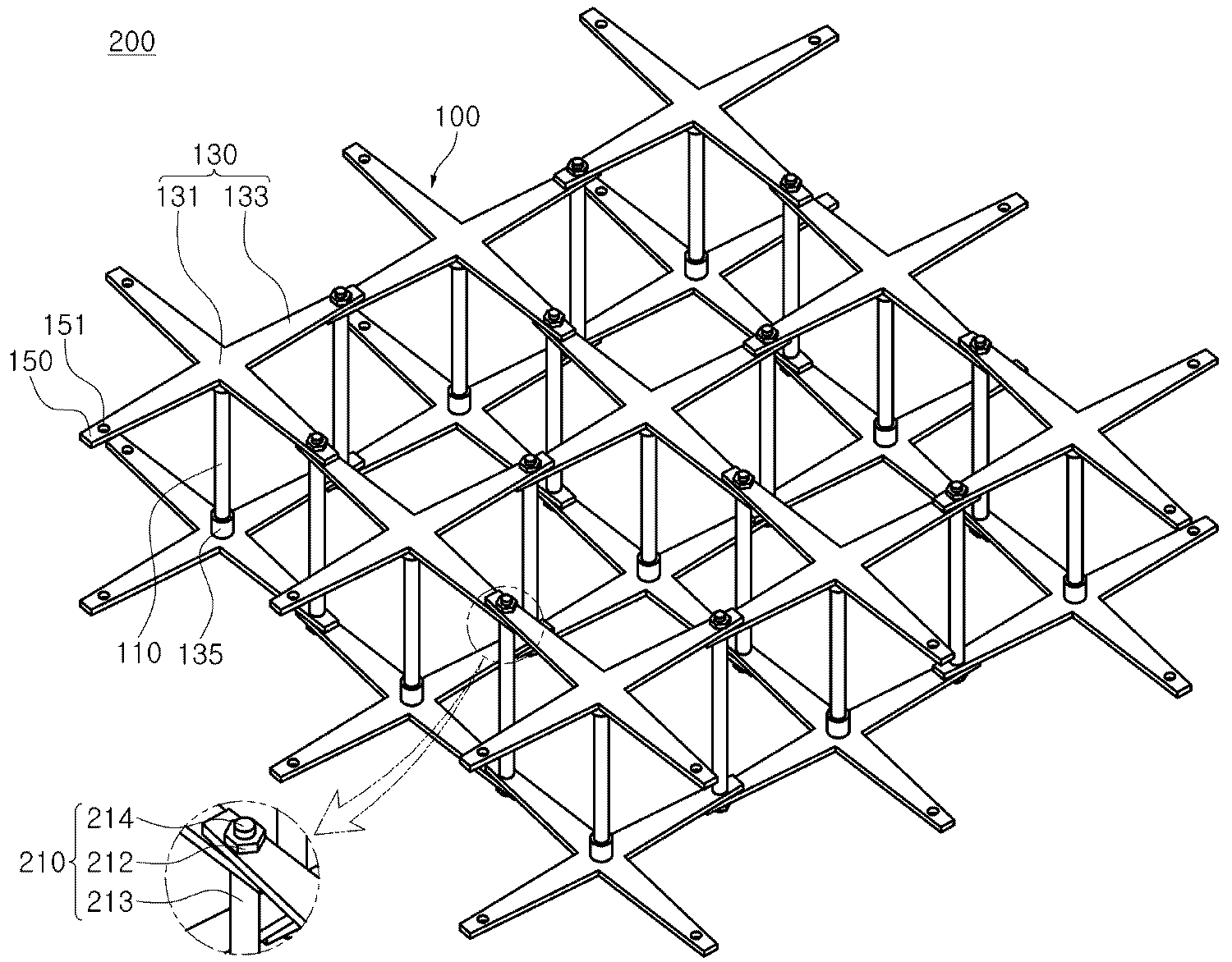
한편, 이하에서는 도 4 내지 도 7을 참조하여 본 발명의 또 다른 측면에 의한 연약지반 보강구조체(200)에 대하여 살펴본다. Hereinafter, a soft
도 4는 본 발명의 일실시예에 의한 연약지반 보강구조체(200)를 나타내는 사시도이고, 도 5는 도 4에 도시된 연약지반 보강구조체(200)의 일부를 나타내는 평면도이며, 도 6은 도 4에 도시된 연약지반 보강구조체(200)의 일부를 나타내는 입면도이고, 도 7은 본 발명의 다른 실시예에 의한 연약지반 보강구조체(200)를 나타내는 입면도이다. FIG. 4 is a perspective view showing a soft
본 발명의 실시예에 의한 연약지반 보강구조체(200)는 상기 강그리드 단위모듈(100)을 연결하여 격자형태로 배치되게 하여 건축물(300)이 설치되는 지반, 특히 연약지반에 설치되어 지반의 허용지지력을 증가시키도록 구성될 수 있다. 이때, 상기 건축물은 건축구조물과 토목구조물 등의 건설구조물을 통합한 개념이다.
The soft
본 발명의 실시예에 의한 연약지반 보강구조체(200)는, 도시된 실시예와 같이, 상기 강그리드 단위모듈(100)이 수평방향으로 복수 개가 연결되어 구성될 수 있다. The soft
또한, 복수의 강그리드 단위모듈(100)은 상기 아암부(133)의 단부가 중첩되게 연결되어 격자형태로 배치되도록 할 수 있다. In addition, the plurality of steel
이에 따라, 상기 보강구조체(200)는 도 4에 도시된 실시예와 같이, 상, 하부 수평부재(130)들과 상기 수직부재(110)로 구성된 입체 강그리드 구조로 형성될 수 있다. 이와 같은 연약지반 보강구조체(200)는 미리 제작된 단위모듈을 수평으로 복수 개를 구비함으로써 지반을 보강하는 입체 구조체로 형성되므로 연약지반을 보강하는 구조체의 제작성과 시공성이 향상될 수 있다. 4, the reinforcing
한편, 이웃하게 연결되는 상기 강그리드 단위모듈(100)은 상기 결합부(150)에 구비된 연결재 삽입구(151)가 서로 연통되도록 중첩되게 연결될 수 있다. 그리고, 연통된 상기 연결재 삽입구(151)를 통해 결합되어 상기 복수의 강그리드 단위모듈(100)을 연결하는 연결재(210)를 더 포함할 수 있다. Meanwhile, the steel
이와 같이, 연결되는 상기 결합부(150)가 중첩되게 연결되고 연통된 연결재 삽입구(151)를 통해 상기 연결재(210)를 결합하므로, 지반보강용 입체그리드 구조의 연결부분이 견고해지는 효과를 얻을 수 있다. 이에 따라, 상기 보강구조체(200)가 설치되는 지반의 상부에 설치되는 건축물의 구조적 안정성이 향상될 수 있다. As described above, since the
도 6 및 도 7에는 상기 연결재(210)의 실시예가 도시되어 있다. Figs. 6 and 7 show an embodiment of the
먼저, 도 6에 도시된 상기 연결재(210)의 일 예를 참조하면, 상기 연결재(210)는, 상기 연결재 삽입구(151)에 관통 체결되는 체결볼트(211)와 상기 체결볼트(211)를 고정하는 고정너트(212)로 구성될 수 있다. 6, the
즉, 상기 복수의 강그리드 단위모듈(100)을 각 단위모듈의 아암부(133)의 단부가 중첩되게 배치한 후 상기 연결재 삽입구(151)에 체결볼트(211)를 삽입한 후 상기 고정너트(212)로 고정함으로써 상기 복수의 강그리드 단위모듈(100)을 연결할 수 있다. That is, after arranging the plurality of steel
한편, 도 7에 도시된 상기 연결재(210)의 다른 예를 참조하면, 상기 연결재(210)는, 상측 수평부재(130)의 결합부(150)와 하측 수평부재(130)의 결합부(150) 사이를 연결하도록 수직으로 배치되는 몸체부(213)와, 상기 몸체부(213)의 양 단부에 연장되어 형성되며, 외주면에 나사산이 형성되어 상기 결합부(150)에 구비된 연결재 삽입구(151)에 나사결합되는 나사산부(214)와, 상기 나사산부(214)에 체결되는 고정너트(212)를 포함하여 구성될 수 있다. 7, the
즉, 상기 복수의 강그리드 단위모듈(100)을 각 단위모듈의 아암부(133)의 단부가 중첩되게 배치한 후 상기 상,하부 수평부재(130)의 결합부(150) 사이에 상기 연결재(210)의 몸체부(213)를 수직으로 설치한 후 상기 나사산부(214)를 연통되는 상기 연결재 삽입구(151)들에 끼운후 돌려서 결합할 수 있다. 그리고, 상기 나사산부(214)에 고정너트(212)를 체결하여 상기 연결재(210)가 이탈되어 결합부(150)가 분리되는 것을 방지하도록 고정할 수 있다. That is, after the plurality of steel
이때, 상기 몸체부(213)는 상기 수직부재(110)와 마찬가지로 강봉이나 핀 등의 강재로 제공될 수 있으며, 단면은 다양하게 형성될 수 있다. At this time, the
이와 같이, 도 6 및 도 7에 도시된 실시예들에 의해, 상기 연결재(210)는 상기 결합부(150)에 볼트 체결되고 관통삽입되어 결합됨으로써 용이하고 견고하게 상기 강그리드 단위모듈(100)을 연결할 수 있다. 그리고, 상기 연결재(210)를 상기 상, 하부를 연결하는 강봉 또는 핀 등으로 구성함으로써 지상의 건축물(300)에서 전달되는 하중에 대한 저항력이 향상되어 연약지반의 지지력이 더욱 증대될 수 있다. 6 and 7, the
또한, 연결되는 상기 강그리드 단위모듈(100)의 개수는, 연약지반의 환경이나, 시공되는 건축물(300)의 면적 및 하중에 따라 결정될 수 있다. 상기 강그리드 단위모듈(100)은 공장에서 모듈단위로 제작되므로, 현장의 상태에 따라 개수를 달리하여 수평으로 접합설치하면 되므로 시공성 및 보강구조체(200)의 제작성이 향상될 수 있다.
The number of the steel
한편, 이하에서는 도 1 내지 도 8을 참조하여 본 발명의 또 다른 측면에 의한 연약지반 강화시공방법에 대하여 살펴본다.Hereinafter, a soft ground reinforcement construction method according to another aspect of the present invention will be described with reference to FIGS. 1 to 8. FIG.
이하에서는, 본 발명의 실시예에 의한 상기 강그리드 단위모듈(100)과 상기 연약지반 보강구조체(200)와 동일한 구성에 대한 자세한 설명은 생략한다. Hereinafter, detailed description of the same components as those of the steel
본 발명의 실시예에 의한 연약지반 강화시공방법은, 상기 강그리드 단위모듈(100)을 제작하는 강그리드 단위모듈 제작단계(S110)와, 상기 강그리드 단위모듈(100)을 격자형태로 복수 개를 배치하고 상기 아암부(133)의 단부를 수평으로 연결하여 연약지반 보강구조체(200)를 제작하는 보강구조체 제작단계(S130)와, 상기 연약지반 보강구조체(200)를 지면에 안착시키는 보강구조체 설치단계(S150)와, 건축물(300)의 기초부(330)와 상기 보강구조체(200)가 일체로 결합되도록 상기 보강구조체(200)가 매설되게 지반에 콘크리트를 타설하는 콘크리트 타설단계(S170)를 포함하여 구성될 수 있다. The soft ground reinforcement construction method according to an embodiment of the present invention includes a steel grid unit module manufacturing step S110 for manufacturing the steel
상기 강그리드 단위모듈 제작단계(S110)는, 상술한 바와 같이 상기 수직부재(110)와 상기 수직부재(110) 상, 하부로 상기 수평부재(130)를 결합설치함으로써 수행될 수 있다. 이때, 상기 수직부재(110)는 상기 수평부재(130)의 중심부(131)에 구비된 고정구(135)에 단부가 끼워짐으로써 볼트체결될 수 있다. The steel grid unit module manufacturing step S110 may be performed by joining the
상기 강그리드 단위모듈 제작단계(S110)는, 상기 보강구조체(200)를 상기 지반에 설치하기 전에 공장제작이나 현장제작을 통해서 수행될 수 있으나, 바람직하게는 공장에서 모듈단위로 제작하여 현장에 필요한 만큼 이송될 수 있다.The steel grid unit module manufacturing step (S110) may be carried out through factory production or on-site production before installing the reinforcing
한편, 상기 보강구조체 제작단계(S130)는, 이웃하게 연결되는 상기 강그리드 단위모듈(100)의 결합부(150)에 구비된 연결재 삽입구(151)가 서로 연통되도록 중첩되게 연결하고, 연통된 상기 연결재 삽입구(151)를 통해 연결재(210)를 결합하여 상기 복수의 강그리드 단위모듈(100)을 연결함으로써 수행될 수 있다. In the meantime, the reinforcing structure manufacturing step (S130) may include the step of connecting the connecting
이때, 상기 연결재(210)는 상기 연결재 삽입구(151)와 볼트체결될 수 있다. At this time, the
상기 보강구조체 제작단계(S130)는 공장이나 현장에서 수행될 수 있으며, 현장에서 수행되는 경우에는 상기 보강구조체(200)를 지반의 정해진 위치에 설치하기 전에 조립하여 제작할 수 있다. The step of constructing the reinforcing structure (S130) may be performed at a factory or a site. If the reinforcing
또한, 상기 보강구조체(200)는 상기 강그리드 단위모듈(100)의 결합개수에 따라 크기가 결정될 수 있다. 따라서, 대규모의 연약지반을 보강하기 위한 경우에도 미리 제작된 상기 강그리드 단위모듈(100)을 연결접합함으로써 제작할 수 있으므로, 대규모 연약지반 보강이나 대규모 건축물 설치시에도 공사기간을 단축시키는 효과를 얻을 수 있다. Also, the size of the reinforcing
이 후에, 상기 연약지반 보강구조체(200)를 지면에 안착시킴으로써 상기 보강구조체 설치단계를 수행할 수 있다. Thereafter, the soft
이때, 상기 보강구조체(200)는 상기한 바와 같이 공장이나 현장에서 미리 제작한 후 크레인 등으로 양중되어 지면(E)에 안착시킴으로써 설치될 수 있다. 이와 같이, 입체 보강구조체(200)를 미리 제작하여 현장에 설치함으로써 시공성이 향상될 수 있다. At this time, the reinforcing
한편, 도 8에 도시된 실시예와 같이, 상기 보강구조체(200) 설치단계는, 상기 연약지반 보강구조체(200)가 건축물(300)의 기둥(310)의 하부 위치에 배치되게 설치할 수 있다. 8, the step of installing the reinforcing
즉, 건축물(300)의 기둥(310) 하부에는 하중집중현상으로 응력이 집중되어 기둥하부 지반의 허용지지력이 감소될 수 있다. 따라서, 상기 건축물(300)의 기둥의 하부 위치에 상기 보강구조체(200)를 설치하여 연약지반의 국부적인 부분의 허용지지력을 증대시킬 수 있다. In other words, stress is concentrated on the lower portion of the
다만, 상기 연약지반 보강구조체(200)가 배치되는 위치는 상기 건축물(300)의 기둥(310) 하부에 한정되는 것은 아니며, 건축물(300) 하부의 연약지반 전반에 걸쳐 설치될 수도 있으며, 상기 기둥 이외에 하중이 집중되어 보강이 필요한 부분에 국부적으로 설치될 수도 있다. The location where the soft
한편, 상기 콘크리트 타설단계(S170)는, 지반에 상기 연약지반 보강구조체(200)를 설치한 후 입체적으로 결합된 상기 수평부재(130)와 수직부재(110)로 생성되는 공간부에 콘크리트(C)를 채움으로써 수행될 수 있다. 콘크리트를 타설함으로써 상기 결합부(150)가 콘크리트에 매설되어 상기 강그리드 단위모듈(100)의 연결부분이 더욱 견고해질 수 있다. The concrete pouring step S170 may include placing the soft
또한, 콘크리트 타설시에 상기 건축물(300)의 기초부(330)를 설치를 병행하여, 상기 콘크리트에 의해 상기 건축물(300)의 기초부(330)와 상기 보강구조체(200)가 일체로 결합되게 할 수 있다. The
한편, 콘크리트 타설단계(S170) 전에, 타설되는 콘크리트와 일체화되어 상기 건축물(300)의 기초부(330)를 보강토록, 상기 수평부재(130)의 상면에 수직으로 보강부재(230)를 설치하는 보강부재 설치단계를 포함할 수 있다. The reinforcing
즉, 상기 보강부재(230)는 상기 수평부재(130)의 상면, 즉 상기 수직부재(110)가 접합되지 않는 면에 설치되어 상기 건축물(300)의 기초부(330)의 하면을 지지할 수 있다. 상기 보강부재(230)와 상기 수평부재(130)의 연결방식에는 제한이 없으며, 예를 들어 상기 수직부재(110)와 상기 수평부재(130)의 결합방식과 유사하게 설치할 수 있다. 즉, 상기 수평부재(130)의 중심부(131) 상면에 고정부재를 설치하고 상기 보강부재(230)의 단부를 고정함으로써 상기 보강부재(230)를 상기 수평부재(130)에 대하여 수직으로 설치할 수 있다. 또한, 상기 보강부재(230)는 강봉이나 핀 등의 강재가 다양하게 적용될 수 있다. That is, the reinforcing
이 후, 상기 콘크리트가 타설되면 상기 보강부재(230)가 매설됨으로써 상기 건축물(300)의 기초부(330)와 상기 보강구조체(200)가 일체로 결합될 수 있다.
Thereafter, when the concrete is poured, the reinforcing
이와 같은 본 발명의 실시예에 의한 연약지반 보강용 강그리드 단위모듈과 이를 이용한 보강구조체 및 연약지반 강화시공방법에 의하면, 연결재를 이용하여 강그리드 단위모듈을 견고하게 연결하여 보강구조체를 제작하므로, 조립 및 해체가 용이하고, 설치후 이탈이나 이격을 방지할 수 있어 시공성과 구조적 안정성이 향상된 보강구조체를 제공하는 효과를 얻을 수 있다. 따라서, 내구성이 우수한 건축물을 시공할 수 있다.
According to the steel grid unit module for soft ground reinforcement according to the embodiment of the present invention and the reinforcement structure and the soft ground reinforcement construction method using the unit, the steel grid unit module is rigidly connected by using the connecting material, It is possible to obtain an effect of providing a reinforced structure which is easy to assemble and disassemble, can prevent departure or separation after installation, and has improved workability and structural stability. Therefore, a building having excellent durability can be constructed.
본 발명은 지금까지 특정한 실시 예에 관련하여 도시하고 설명하였지만, 이하의 특허청구범위에 의해 마련되는 본 발명의 정신이나 분야를 벗어나지 않는 한 도내에서 본 발명이 다양하게 개조 및 변화될 수 있다는 것을 당 업계에서 통상의 지식을 가진 자는 용이하게 알 수 있음을 밝혀두고자 한다.
While the present invention has been particularly shown and described with reference to specific embodiments thereof, it will be apparent to those skilled in the art that various modifications and variations can be made in the present invention without departing from the spirit or scope of the invention, It will be appreciated that those skilled in the art will readily understand the present invention.
100 : 연약지반 보강용 강그리드 단위모듈 110 : 수직부재
130 : 수평부재 131 : 중심부
133 : 아암부 150 : 결합부
151 : 연결재 삽입구 200 : 연약지반 보강구조체
210 : 연결재 230 : 보강부재 100: Steel grid unit for soft ground reinforcement module 110: Vertical member
130: horizontal member 131: center
133: arm portion 150:
151: connector fitting 200: soft ground reinforcement structure
210: connecting member 230: reinforcing member
Claims (14)
상기 수직부재는 상기 수평부재의 중심부와 연결되며, 상기 아암부의 단부에는 결합부가 형성되고,
복수의 상기 강그리드 단위모듈은 상기 아암부의 단부가 연결되어 격자형으로 배치되며,
이웃하게 연결되는 상기 강그리드 단위모듈은, 상기 결합부에 구비된 연결재 삽입구가 서로 연통되도록 중첩되게 연결된 상태에서, 상측 수평부재의 결합부의 하면과 하측 수평부재의 결합부의 상면 사이를 수직방향으로 연결하면서 상기 상측 수평부재의 아암부의 단부를 지지하는 연결재에 의해 연결되는,
강그리드 단위모듈을 이용한 연약지반 보강구조체.
A vertical member; And a horizontal member which is composed of a plate member coupled to upper and lower sides of the vertical member and has a plurality of arms integrally joined in a cross shape at a central portion, A soft ground reinforcement structure formed by connecting a plurality of soft ground reinforcement structures,
Wherein the vertical member is connected to the central portion of the horizontal member, the coupling portion is formed at the end of the arm portion,
Wherein the plurality of the steel grid unit modules are disposed in a lattice shape with their end portions connected to each other,
The steel grid unit module connected adjacent to each other is connected vertically between the lower surface of the coupling portion of the upper horizontal member and the upper surface of the coupling portion of the lower horizontal member in a state in which the coupling- The upper horizontal member being connected to the lower horizontal member by a connecting member for supporting an end of the upper horizontal member,
Soft ground reinforcement structure using steel grid unit module.
상기 수평부재는, 상기 수직부재와 접합되는 중심부의 일면에 상기 수직부재의 단부가 끼워지도록 고정홈을 구비한 고정구가 일체로 형성된 것을 특징으로 하는 강그리드 단위모듈을 이용한 연약지반 보강구조체.
The method according to claim 1,
Wherein the horizontal member is integrally formed with a fastener having a fixing groove so that an end of the vertical member is fitted to one surface of a center portion joined to the vertical member.
상기 고정구는, 상기 수직부재의 단부가 나사결합되도록 상기 고정구의 내주면에 나사산이 형성된 것을 특징으로 하는 강그리드 단위모듈을 이용한 연약지반 보강구조체.
3. The method of claim 2,
Wherein the fastener is formed with threads on the inner circumferential surface of the fastener so that the end of the vertical member is threaded.
상기 아암부는, 단부로 갈수로 폭이 좁아지는 것을 특징으로 하는 강그리드 단위모듈을 이용한 연약지반 보강구조체.
The method according to claim 1,
Wherein the arm portion is narrowed toward the end portion of the soft ground reinforcement structure.
상기 상측 수평부재의 결합부의 하면과 상기 하측 수평부재의 결합부의 상면 사이를 연결하도록 수직으로 배치되는 몸체부;
상기 몸체부의 양 단부에 연장되어 형성되며, 외주면에 나사산이 형성되어 상기 연결재 삽입구에 삽입되어 설치되는 나사산부; 및,
상기 나사산부에 체결되는 고정너트;
를 포함하는 것을 특징으로 하는 강그리드 단위모듈을 이용한 연약지반 보강구조체.
The connector according to claim 1,
A body portion vertically arranged to connect between a lower surface of the coupling portion of the upper horizontal member and an upper surface of the coupling portion of the lower horizontal member;
A threaded portion extending from both ends of the body portion and having threads formed on an outer circumferential surface thereof and inserted into the connecting member insertion port; And
A fixing nut fastened to the threaded portion;
And a soft ground reinforcement structure using the steel grid unit module.
건축물의 기초부와 상기 보강구조체가 일체로 결합되도록 상기 보강구조체가 매설되게 지반에 콘크리트를 타설하는 콘크리트 타설단계;
를 포함하는 강그리드 단위모듈을 이용한 연약지반 강화시공방법.
A reinforcing structure mounting step of placing the soft ground reinforcement structure using the steel grid unit module according to any one of claims 1, 2, 3, 5, and 9 on the ground; And
A concrete casting step of placing concrete in a ground with the reinforcing structural body embedded so that the foundation of the building and the reinforcing structural body are integrally joined;
A method of strengthening soft ground using a steel grid unit module comprising a plurality of steel grid units.
상기 보강구조체 설치단계는, 상기 연약지반 보강구조체가 건축물의 기둥의 하부 위치에 배치되게 설치함으로써 수행되는 것을 특징으로 하는 강그리드 단위모듈을 이용한 연약지반 강화시공방법.
11. The method of claim 10,
Wherein the step of installing the reinforcing structure is performed by installing the soft ground reinforcement structure at a lower position of a column of the building.
타설되는 콘크리트와 일체화되어 상기 건축물의 기초부를 보강토록, 상기 수평부재의 상면에 수직으로 보강부재를 설치하는 보강부재 설치단계;를 포함하는 것을 특징으로 하는 강그리드 단위모듈을 이용한 연약지반 강화시공방법. 11. The method of claim 10, wherein before the concrete pouring step
And installing a reinforcing member vertically on the upper surface of the horizontal member so as to be integrated with the concrete to be laid to reinforce the foundation of the building. .
Priority Applications (1)
| Application Number | Priority Date | Filing Date | Title |
|---|---|---|---|
| KR1020120100108A KR101440552B1 (en) | 2012-09-10 | 2012-09-10 | Reinforcement structure and method for reinforcing soft ground using unit module of steel grid |
Applications Claiming Priority (1)
| Application Number | Priority Date | Filing Date | Title |
|---|---|---|---|
| KR1020120100108A KR101440552B1 (en) | 2012-09-10 | 2012-09-10 | Reinforcement structure and method for reinforcing soft ground using unit module of steel grid |
Publications (2)
| Publication Number | Publication Date |
|---|---|
| KR20140034965A KR20140034965A (en) | 2014-03-21 |
| KR101440552B1 true KR101440552B1 (en) | 2014-09-17 |
Family
ID=50645092
Family Applications (1)
| Application Number | Title | Priority Date | Filing Date |
|---|---|---|---|
| KR1020120100108A Expired - Fee Related KR101440552B1 (en) | 2012-09-10 | 2012-09-10 | Reinforcement structure and method for reinforcing soft ground using unit module of steel grid |
Country Status (1)
| Country | Link |
|---|---|
| KR (1) | KR101440552B1 (en) |
Families Citing this family (1)
| Publication number | Priority date | Publication date | Assignee | Title |
|---|---|---|---|---|
| KR102062254B1 (en) * | 2017-10-26 | 2020-01-03 | 부산대학교 산학협력단 | Non-point source reduction using ground reinforcement grid and road pavement structure using it |
Citations (3)
| Publication number | Priority date | Publication date | Assignee | Title |
|---|---|---|---|---|
| JPS59125529U (en) * | 1983-02-08 | 1984-08-23 | 三井プレコン株式会社 | artificial ground |
| KR100780216B1 (en) * | 2007-05-03 | 2007-11-27 | 주식회사 남원건설엔지니어링 | Method to install honeycomb mat |
| JP2009155997A (en) * | 2007-12-28 | 2009-07-16 | Hyokin Rei | Structure of fitting type spatial lattice |
-
2012
- 2012-09-10 KR KR1020120100108A patent/KR101440552B1/en not_active Expired - Fee Related
Patent Citations (3)
| Publication number | Priority date | Publication date | Assignee | Title |
|---|---|---|---|---|
| JPS59125529U (en) * | 1983-02-08 | 1984-08-23 | 三井プレコン株式会社 | artificial ground |
| KR100780216B1 (en) * | 2007-05-03 | 2007-11-27 | 주식회사 남원건설엔지니어링 | Method to install honeycomb mat |
| JP2009155997A (en) * | 2007-12-28 | 2009-07-16 | Hyokin Rei | Structure of fitting type spatial lattice |
Also Published As
| Publication number | Publication date |
|---|---|
| KR20140034965A (en) | 2014-03-21 |
Similar Documents
| Publication | Publication Date | Title |
|---|---|---|
| KR101890860B1 (en) | Double PC wall assembly and construction method of composite wall structure using the same | |
| JP5023219B2 (en) | Precast temporary structure and construction method thereof | |
| KR101687495B1 (en) | Partial top-down construction method for building underground structures | |
| KR101698995B1 (en) | the improved prefabricated reinforcing bar net unit for easy mechanical Re-bar splicing, spacing and leveling on the site | |
| JP2011157812A (en) | Retaining wall and construction method therefor | |
| JP6430271B2 (en) | Footing-integrated foundation pile structure and construction method of footing-integrated foundation pile | |
| KR20160079458A (en) | Hybrid bridge connecting structure and method for constructing thereof | |
| KR20140047924A (en) | Construction method of cast-in-place step retaining wall using pc panel needless of concrete forms for slope reinforcement | |
| KR101183785B1 (en) | Fixing structure for column to footing and column-footing connecting structure using the same | |
| JP3241998U (en) | Slope shoring structure | |
| KR101227680B1 (en) | Connection method for cast-in-place concrete pile and drilled pile | |
| KR101440552B1 (en) | Reinforcement structure and method for reinforcing soft ground using unit module of steel grid | |
| KR101200993B1 (en) | Precast concrete column material for permanent column pre-establishment method | |
| KR101893658B1 (en) | Apparatus for a mold for joint part between case in place uper end of pile and rear bridge for monopile construnction | |
| KR101249603B1 (en) | Steel pipe installing structure for resistance in vertical stress of none-excavation underground structure and construction method at the same | |
| KR200440989Y1 (en) | Block, coupler, and reinforced earth retaining wall structure using the same | |
| KR20160106357A (en) | PHC Pile having Steel Bands, Retaining Wall using such PHC Piles, and Constructing Method of such Retaining Wall | |
| KR101058982B1 (en) | Interlaminar beam of soil wall composed of PA piles and construction method | |
| KR101545713B1 (en) | Composite type cutoff wall of steel temporary facility and construction method of the same | |
| KR102123666B1 (en) | Implant pile installer in architecture foundation system and a universal implant pile method | |
| KR101627658B1 (en) | Pile beam with shear-keys and Construction method of mixed bridge using Piled beams with shear-key | |
| KR100545398B1 (en) | Reinforced soil retaining wall and its installation method | |
| KR100823348B1 (en) | Steel composite retaining wall construction method | |
| KR101803767B1 (en) | Assembly for reinforcing head part of steel tube pile and steel tubepile assembly including the same | |
| JP6496464B2 (en) | Joint structure of ready-made pillar and footing |
Legal Events
| Date | Code | Title | Description |
|---|---|---|---|
| A201 | Request for examination | ||
| PA0109 | Patent application |
St.27 status event code: A-0-1-A10-A12-nap-PA0109 |
|
| PA0201 | Request for examination |
St.27 status event code: A-1-2-D10-D11-exm-PA0201 |
|
| PN2301 | Change of applicant |
St.27 status event code: A-3-3-R10-R13-asn-PN2301 St.27 status event code: A-3-3-R10-R11-asn-PN2301 |
|
| D13-X000 | Search requested |
St.27 status event code: A-1-2-D10-D13-srh-X000 |
|
| D14-X000 | Search report completed |
St.27 status event code: A-1-2-D10-D14-srh-X000 |
|
| E902 | Notification of reason for refusal | ||
| PE0902 | Notice of grounds for rejection |
St.27 status event code: A-1-2-D10-D21-exm-PE0902 |
|
| T11-X000 | Administrative time limit extension requested |
St.27 status event code: U-3-3-T10-T11-oth-X000 |
|
| T11-X000 | Administrative time limit extension requested |
St.27 status event code: U-3-3-T10-T11-oth-X000 |
|
| PG1501 | Laying open of application |
St.27 status event code: A-1-1-Q10-Q12-nap-PG1501 |
|
| E13-X000 | Pre-grant limitation requested |
St.27 status event code: A-2-3-E10-E13-lim-X000 |
|
| P11-X000 | Amendment of application requested |
St.27 status event code: A-2-2-P10-P11-nap-X000 |
|
| P13-X000 | Application amended |
St.27 status event code: A-2-2-P10-P13-nap-X000 |
|
| E701 | Decision to grant or registration of patent right | ||
| PE0701 | Decision of registration |
St.27 status event code: A-1-2-D10-D22-exm-PE0701 |
|
| GRNT | Written decision to grant | ||
| PR0701 | Registration of establishment |
St.27 status event code: A-2-4-F10-F11-exm-PR0701 |
|
| PR1002 | Payment of registration fee |
St.27 status event code: A-2-2-U10-U11-oth-PR1002 Fee payment year number: 1 |
|
| PG1601 | Publication of registration |
St.27 status event code: A-4-4-Q10-Q13-nap-PG1601 |
|
| P22-X000 | Classification modified |
St.27 status event code: A-4-4-P10-P22-nap-X000 |
|
| R18-X000 | Changes to party contact information recorded |
St.27 status event code: A-5-5-R10-R18-oth-X000 |
|
| FPAY | Annual fee payment |
Payment date: 20170901 Year of fee payment: 4 |
|
| PR1001 | Payment of annual fee |
St.27 status event code: A-4-4-U10-U11-oth-PR1001 Fee payment year number: 4 |
|
| FPAY | Annual fee payment |
Payment date: 20180903 Year of fee payment: 5 |
|
| PR1001 | Payment of annual fee |
St.27 status event code: A-4-4-U10-U11-oth-PR1001 Fee payment year number: 5 |
|
| P22-X000 | Classification modified |
St.27 status event code: A-4-4-P10-P22-nap-X000 |
|
| FPAY | Annual fee payment |
Payment date: 20190902 Year of fee payment: 6 |
|
| PR1001 | Payment of annual fee |
St.27 status event code: A-4-4-U10-U11-oth-PR1001 Fee payment year number: 6 |
|
| R18-X000 | Changes to party contact information recorded |
St.27 status event code: A-5-5-R10-R18-oth-X000 |
|
| FPAY | Annual fee payment |
Payment date: 20200904 Year of fee payment: 7 |
|
| PR1001 | Payment of annual fee |
St.27 status event code: A-4-4-U10-U11-oth-PR1001 Fee payment year number: 7 |
|
| R18-X000 | Changes to party contact information recorded |
St.27 status event code: A-5-5-R10-R18-oth-X000 |
|
| FPAY | Annual fee payment |
Payment date: 20210902 Year of fee payment: 8 |
|
| PR1001 | Payment of annual fee |
St.27 status event code: A-4-4-U10-U11-oth-PR1001 Fee payment year number: 8 |
|
| PC1903 | Unpaid annual fee |
St.27 status event code: A-4-4-U10-U13-oth-PC1903 Not in force date: 20220905 Payment event data comment text: Termination Category : DEFAULT_OF_REGISTRATION_FEE |
|
| PC1903 | Unpaid annual fee |
St.27 status event code: N-4-6-H10-H13-oth-PC1903 Ip right cessation event data comment text: Termination Category : DEFAULT_OF_REGISTRATION_FEE Not in force date: 20220905 |
|
| R18-X000 | Changes to party contact information recorded |
St.27 status event code: A-5-5-R10-R18-oth-X000 |
|
| R18 | Changes to party contact information recorded |
Free format text: ST27 STATUS EVENT CODE: A-5-5-R10-R18-OTH-X000 (AS PROVIDED BY THE NATIONAL OFFICE) |
|
| R18-X000 | Changes to party contact information recorded |
St.27 status event code: A-5-5-R10-R18-oth-X000 |