KR101394151B1 - Apparatus and method for encoding image using a psycho-visual characteristic - Google Patents
Apparatus and method for encoding image using a psycho-visual characteristic Download PDFInfo
- Publication number
- KR101394151B1 KR101394151B1 KR20070099969A KR20070099969A KR101394151B1 KR 101394151 B1 KR101394151 B1 KR 101394151B1 KR 20070099969 A KR20070099969 A KR 20070099969A KR 20070099969 A KR20070099969 A KR 20070099969A KR 101394151 B1 KR101394151 B1 KR 101394151B1
- Authority
- KR
- South Korea
- Prior art keywords
- value
- pixel
- range
- calculated
- error
- Prior art date
Links
Images

Classifications
-
- H—ELECTRICITY
- H04—ELECTRIC COMMUNICATION TECHNIQUE
- H04N—PICTORIAL COMMUNICATION, e.g. TELEVISION
- H04N19/00—Methods or arrangements for coding, decoding, compressing or decompressing digital video signals
- H04N19/10—Methods or arrangements for coding, decoding, compressing or decompressing digital video signals using adaptive coding
- H04N19/169—Methods or arrangements for coding, decoding, compressing or decompressing digital video signals using adaptive coding characterised by the coding unit, i.e. the structural portion or semantic portion of the video signal being the object or the subject of the adaptive coding
- H04N19/184—Methods or arrangements for coding, decoding, compressing or decompressing digital video signals using adaptive coding characterised by the coding unit, i.e. the structural portion or semantic portion of the video signal being the object or the subject of the adaptive coding the unit being bits, e.g. of the compressed video stream
-
- H—ELECTRICITY
- H04—ELECTRIC COMMUNICATION TECHNIQUE
- H04N—PICTORIAL COMMUNICATION, e.g. TELEVISION
- H04N19/00—Methods or arrangements for coding, decoding, compressing or decompressing digital video signals
- H04N19/10—Methods or arrangements for coding, decoding, compressing or decompressing digital video signals using adaptive coding
- H04N19/102—Methods or arrangements for coding, decoding, compressing or decompressing digital video signals using adaptive coding characterised by the element, parameter or selection affected or controlled by the adaptive coding
- H04N19/103—Selection of coding mode or of prediction mode
- H04N19/11—Selection of coding mode or of prediction mode among a plurality of spatial predictive coding modes
-
- H—ELECTRICITY
- H04—ELECTRIC COMMUNICATION TECHNIQUE
- H04N—PICTORIAL COMMUNICATION, e.g. TELEVISION
- H04N19/00—Methods or arrangements for coding, decoding, compressing or decompressing digital video signals
- H04N19/10—Methods or arrangements for coding, decoding, compressing or decompressing digital video signals using adaptive coding
- H04N19/102—Methods or arrangements for coding, decoding, compressing or decompressing digital video signals using adaptive coding characterised by the element, parameter or selection affected or controlled by the adaptive coding
- H04N19/119—Adaptive subdivision aspects, e.g. subdivision of a picture into rectangular or non-rectangular coding blocks
-
- H—ELECTRICITY
- H04—ELECTRIC COMMUNICATION TECHNIQUE
- H04N—PICTORIAL COMMUNICATION, e.g. TELEVISION
- H04N19/00—Methods or arrangements for coding, decoding, compressing or decompressing digital video signals
- H04N19/10—Methods or arrangements for coding, decoding, compressing or decompressing digital video signals using adaptive coding
- H04N19/102—Methods or arrangements for coding, decoding, compressing or decompressing digital video signals using adaptive coding characterised by the element, parameter or selection affected or controlled by the adaptive coding
- H04N19/124—Quantisation
-
- H—ELECTRICITY
- H04—ELECTRIC COMMUNICATION TECHNIQUE
- H04N—PICTORIAL COMMUNICATION, e.g. TELEVISION
- H04N19/00—Methods or arrangements for coding, decoding, compressing or decompressing digital video signals
- H04N19/10—Methods or arrangements for coding, decoding, compressing or decompressing digital video signals using adaptive coding
- H04N19/134—Methods or arrangements for coding, decoding, compressing or decompressing digital video signals using adaptive coding characterised by the element, parameter or criterion affecting or controlling the adaptive coding
- H04N19/136—Incoming video signal characteristics or properties
- H04N19/14—Coding unit complexity, e.g. amount of activity or edge presence estimation
-
- H—ELECTRICITY
- H04—ELECTRIC COMMUNICATION TECHNIQUE
- H04N—PICTORIAL COMMUNICATION, e.g. TELEVISION
- H04N19/00—Methods or arrangements for coding, decoding, compressing or decompressing digital video signals
- H04N19/10—Methods or arrangements for coding, decoding, compressing or decompressing digital video signals using adaptive coding
- H04N19/134—Methods or arrangements for coding, decoding, compressing or decompressing digital video signals using adaptive coding characterised by the element, parameter or criterion affecting or controlling the adaptive coding
- H04N19/154—Measured or subjectively estimated visual quality after decoding, e.g. measurement of distortion
-
- H—ELECTRICITY
- H04—ELECTRIC COMMUNICATION TECHNIQUE
- H04N—PICTORIAL COMMUNICATION, e.g. TELEVISION
- H04N19/00—Methods or arrangements for coding, decoding, compressing or decompressing digital video signals
- H04N19/10—Methods or arrangements for coding, decoding, compressing or decompressing digital video signals using adaptive coding
- H04N19/169—Methods or arrangements for coding, decoding, compressing or decompressing digital video signals using adaptive coding characterised by the coding unit, i.e. the structural portion or semantic portion of the video signal being the object or the subject of the adaptive coding
- H04N19/182—Methods or arrangements for coding, decoding, compressing or decompressing digital video signals using adaptive coding characterised by the coding unit, i.e. the structural portion or semantic portion of the video signal being the object or the subject of the adaptive coding the unit being a pixel
-
- H—ELECTRICITY
- H04—ELECTRIC COMMUNICATION TECHNIQUE
- H04N—PICTORIAL COMMUNICATION, e.g. TELEVISION
- H04N19/00—Methods or arrangements for coding, decoding, compressing or decompressing digital video signals
- H04N19/50—Methods or arrangements for coding, decoding, compressing or decompressing digital video signals using predictive coding
- H04N19/593—Methods or arrangements for coding, decoding, compressing or decompressing digital video signals using predictive coding involving spatial prediction techniques
Abstract
본 발명은 인간의 시감 특성을 고려하여 영상을 부호화하는 장치 및 방법에 관한 것으로, 각 픽셀에 대응하여 예측된 픽셀의 값에 대한 오차값 가운데 인간의 시감 특성상 인지할 수 있는 범위에 해당하는 값만 부호화한다.The present invention relates to an apparatus and a method for encoding an image in consideration of a human sensibility characteristic. The apparatus and method include encoding only a value corresponding to a range that can be perceived by a human sensibility characteristic among error values of predicted pixel values corresponding to each pixel do.
Description
본 발명은 영상을 부호화하는 방법 및 장치에 관한 것으로, 보다 상세하게는 인간의 시감 특성을 고려하여 영상을 부호화하는 방법 및 장치에 관한 것이다.BACKGROUND OF THE
오디오 코딩(audio coding)에서는 인간의 청각 특성을 이용한 심리-음향 모델(psycho-acoustic model)을 적용하여 마스킹 임계값(masking threshold)를 설정한 후 주파수 영역별 비트를 달리 할당하여 부호화한다.In the audio coding, a masking threshold is set by applying a psycho-acoustic model using the human auditory characteristics, and then different bits are assigned to different frequency regions to be encoded.
그리고 비디오 또는 영상 코딩에 있어서도 인간의 시감 특성을 이용하여 코딩하는 기술들이 있다. 예를 들어, YUV 포멧(format)을 사용하는 방법 또는 DCT에서 양자화 행렬(quantization matrix)를 사용하는 방법 등이 있다. 첫째, YUV 포멧의 경우 주로 인간이 색도 변화에 취약하다는 특성을 이용하여 색차(chrominance)에 대한 비트를 적게 할당하는 방법으로 압축을 실시한다. 둘째, DCT에서는 저주파 영역과 고주파 영역으로 구별하고 인간의 시감 특성상 고주파 영역에 둔감한 특성을 이용함으로써 고주파 영역의 양자화를 크게 할당되는 비트를 줄인다.In video and / or image coding, there are techniques for coding using human visual characteristics. For example, using the YUV format, or using a quantization matrix in the DCT. First, in the YUV format, compression is performed by allocating a small number of bits for chrominance using the characteristic that human being is vulnerable to chromaticity change. Second, the DCT distinguishes between a low frequency region and a high frequency region, and uses a characteristic that is insensitive to a high frequency region due to the human sensibility characteristic, thereby reducing a bit to which quantization of a high frequency region is largely allocated.
본 발명이 이루고자 하는 기술적 과제는, 인간의 시감 특성을 고려하여 인지할 수 있는 범위만 부호화하는 장치 및 방법을 제공하는 것이다.SUMMARY OF THE INVENTION An object of the present invention is to provide an apparatus and a method for encoding only a range that can be perceived in consideration of human visual characteristics.
상기의 과제를 이루기 위한 본 발명에 의한 시감 특성을 이용한 영상 부호화 방법은, 영상을 구성하는 픽셀들 중 소정 픽셀의 값과 상기 소정 픽셀에 대응하는 참조 픽셀의 값에 대한 오차를 계산하는 단계; 상기 계산된 오차 가운데 부호화할 범위를 시감 특성상 인지할 수 있는 범위를 판단할 수 있는 기 설정된 방식으로 결정하는 단계; 및 상기 결정된 범위에 해당하는 상기 계산된 오차값만 부호화하는 단계를 포함하는 것을 특징으로 한다.According to an aspect of the present invention, there is provided a method of encoding an image using a luminance characteristic, the method comprising: calculating an error between a value of a predetermined pixel and a value of a reference pixel corresponding to the predetermined pixel; Determining a range to be encoded among the calculated errors as a predetermined method capable of determining a range in which the sensory characteristics can be recognized; And encoding only the calculated error value corresponding to the determined range.
상기의 과제를 이루기 위한 본 발명에 의한 기록 매체는, 영상을 구성하는 픽셀들 중 소정 픽셀의 값과 상기 소정 픽셀에 대응하는 참조 픽셀의 값에 대한 오차를 계산하는 단계; 상기 계산된 오차 가운데 부호화할 범위를 시감 특성상 인지할 수 있는 범위를 판단할 수 있는 기 설정된 방식으로 결정하는 단계; 및 상기 결정된 범위에 해당하는 상기 계산된 오차값만 부호화하는 단계를 포함하는 방법을 컴퓨터에서 실행시키기 위한 프로그램을 기록한 컴퓨터로 읽을 수 있다.According to an aspect of the present invention, there is provided a recording medium including: an error calculation unit calculating an error between a value of a predetermined pixel and a value of a reference pixel corresponding to the predetermined pixel among pixels constituting an image; Determining a range to be encoded among the calculated errors as a predetermined method capable of determining a range in which the sensory characteristics can be recognized; And encoding only the calculated error value corresponding to the determined range. The method may be read by a computer recording a program for causing a computer to execute the method.
상기의 과제를 이루기 위한 본 발명에 의한 시감 특성을 이용한 영상 부호화 장치는, 영상을 구성하는 픽셀들 중 소정 픽셀의 값과 상기 소정 픽셀에 대응하는 참조 픽셀의 값에 대한 오차를 계산하는 오차 계산부; 상기 계산된 오차 가운데 부호화할 범위를 시감 특성상 인지할 수 있는 범위를 판단할 수 있는 기 설정된 방식으로 결정하는 부호화범위 결정부; 및 상기 결정된 범위에 해당하는 상기 계산된 오차값만 부호화하는 부호화부를 포함하는 것을 특징으로 한다.According to an aspect of the present invention, there is provided an image encoding apparatus using an image sensor, the image encoding apparatus including an error calculation unit for calculating an error between a value of a predetermined pixel and a value of a reference pixel corresponding to the predetermined pixel, ; A coding range determination unit that determines a range to be coded among the calculated errors as a predetermined method that can determine a range in which a sensible characteristic can be recognized; And an encoding unit encoding only the calculated error value corresponding to the determined range.
이하, 첨부된 도면들을 참조하여 본 발명에 따른 시감 특성을 이용한 영상 부호화 장치 및 방법의 실시예에 대해 상세히 설명한다.DETAILED DESCRIPTION OF THE PREFERRED EMBODIMENTS Hereinafter, embodiments of an image encoding apparatus and method using a spectral characteristic according to the present invention will be described in detail with reference to the accompanying drawings.
도 1은 본 발명에 의한 시감 특성을 이용한 영상 부호화 장치에 대한 일 실시예를 블록도로 도시한 것으로서, 시감 특성을 이용한 영상 부호화 장치는 예측부(100), 오차 계산부(110), 부호화범위 결정부(120) 및 부호화부(130)를 포함하여 이루어진다.FIG. 1 is a block diagram of an image encoding apparatus according to an embodiment of the present invention. Referring to FIG. 1, an image encoding apparatus using a spectral characteristic includes a
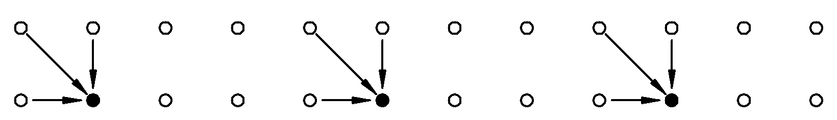
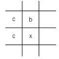
예측부(100)는 입력단자 IN으로부터 영상을 구성하는 픽셀들을 입력받아 기 설정된 방식에 따라 각 픽셀에 대응하는 참조 픽셀의 값을 예측한다. 도 10은 예측부(100)에서 소정 픽셀의 값을 예측하는 일 실시예를 도시한 개념도이다. 도 10에서는 소정 픽셀에 대하여 상 방향, 좌 방향 및 좌상 방향에 마련된 픽셀들의 값을 이용하여 소정 픽셀의 값을 예측할 수 있다. 예측부(100)에서 참조 픽셀의 값을 예측하는 데 이용하는 기 설정된 방식의 일 실시예로 엣지 검출법(edge detecting method)을 사용하여 예측할 수 있다. 이러한 엣지 검출법으로 IEEE Trans. On Consumer Electronics, Vol 47, No.3, 2001, pp466-476 에 있는 "Two low cost algorithms for improved diagonal edge detection in JPEG-LS" 에 개시된 방법을 사용할 수 있다. 엣지 검출법을 이용하여 소정 픽셀 'x'의 값을 예측하는 일 실시예를 도 11을 이용하여 설명하기로 한다. 픽셀 'x'에 대한 에지 검출법의 알고리즘은 다음과 같다.The
if (c >= max(a,b)) P = min(a,b);if (c > = max (a, b)) P = min (a, b);
else{ else {
if (c <= min(a,b)) P = max(a,b);if (c < = min (a, b)) P = max (a, b);
else P = a+b-c;else P = a + b-c;
}}
여기서, 'P'는 'x' 픽셀에 대응하는 참조 픽셀의 값이며, 'a'는 좌 방향에 위치한 픽셀의 값이고, 'b'는 상 방향에 위치한 픽셀의 값이며, 'c'는 좌상 방향에 위치한 픽셀의 값이다.Here, 'P' is the value of the reference pixel corresponding to the 'x' pixel, 'a' is the value of the pixel located in the left direction, 'b' is the value of the pixel located in the upward direction, 'c' Lt; RTI ID = 0.0 > direction.
이 알고리즘에 의하면, 참조 픽셀의 값 'P'는 엣지(edge)가 수평 방향인지 수직 방향인지 여부와 'a' 와 'b' 중에 큰 값이 무엇인지에 따라 결정된다. 만일 'a' 및 'b' 가운데 더 큰 값 보다 'c'가 더 크거나 같다고 가정하면, 'a' 및 'b' 가운데 더 작은 값이 'a'일 경우 수평 방향의 엣지를 가지며 참조 픽셀의 값 'P'는 'a'로 결정되고, 'a' 및 'b' 가운데 더 작은 값이 'b'일 경우 수직 방향의 에지를 가지며 참조 픽셀의 값 'P'는 'b'로 결정된다. 반면에 'a' 및 'b' 가운데 더 작은 값이 'c' 더 크거나 같다고 가정하면, 'a' 및 'b' 가운데 더 큰 값이 'a'일 경우 수평 방향의 엣지를 가지며 참조 픽셀의 값 'P'는 'a'로 결정되고, 'a' 및 'b' 가운데 더 큰 값이 'b'일 경우 수직 방향의 엣지를 가지며 참조 픽셀의 값 'P'는 'b'로 결정된다. 또한, 'c'가 'a' 및 'b' 가운데 더 작은 값 보다 크고 'a' 및 'b' 가운데 더 큰 값 보다 작다고 가정하면, 엣지의 방향을 판정하기 어려우므로 참조 픽셀의 값 'P'는 'a', 'b', 'c' 모두를 고려하여 'a'에 'b'를 가산하고 'c'를 감산 한 값으로 결정한다.According to this algorithm, the value 'P' of the reference pixel is determined according to whether the edge is horizontal or vertical and what is a large value between 'a' and 'b'. Assuming that 'c' is greater than or equal to the larger of 'a' and 'b', if the smaller of 'a' and 'b' is 'a' The value 'P' is determined as 'a', and if the smaller value of 'a' and 'b' is 'b', the edge has a vertical edge and the reference pixel value 'P' is determined as 'b'. On the other hand, assuming that the smaller value of 'a' and 'b' is greater than or equal to 'c', if the larger of 'a' and 'b' is 'a' The value 'P' is determined as 'a', and when a larger value of 'a' and 'b' is 'b', the edge has a vertical direction and the reference pixel value 'P' is determined as 'b'. Also, assuming that 'c' is larger than a smaller value of 'a' and 'b' and smaller than a larger value of 'a' and 'b', it is difficult to determine the direction of the edge, Is determined by adding 'b' to 'a' and subtracting 'c', considering both 'a', 'b' and 'c'.
오차 계산부(110)는 입력단자 IN으로부터 입력받은 픽셀들의 값과 예측부(100)에서 각 픽셀에 대응하여 예측한 참조 픽셀의 값에 대한 오차(error)를 계산한다.The
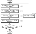
부호화범위 결정부(120)는 오차 계산부(110)에서 계산된 오차 가운데 부호화할 범위를 결정한다. 부호화범위 결정부(120)에서 범위를 결정함에 있어서, 인간의 시감 특성상 인지할 수 있는 범위를 판단할 수 있는 기 설정된 방식을 이용한다. 다시 말하면, 부호화범위 결정부(120)는 오차 계산부(110)에서 계산된 오차 가운데 인간의 시감 특성상 인지할 수 있는 상위 비트에 해당하는 값과 인간의 시감 특성상 인지할 수 없는 하위 비트에 해당하는 값을 구별한다.The coding
이러한 부호화범위 결정부(120)의 실시예로 도 2, 3, 및 4가 있다.Examples of the coding
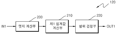
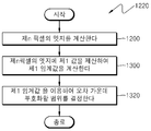
도 2는 소정 픽셀의 엣지를 이용하여 오차 계산부(110)에서 계산된 오차 가운데 부호화할 범위를 결정하는 일 실시예를 블록도로 도시한 것으로서, 부호화범위 결정부(120)는 엣지 계산부(200), 제1 임계값 계산부(210) 및 범위 결정부(220)를 포함하여 이루어진다.FIG. 2 is a block diagram of an embodiment for determining a range to be coded based on an error calculated by the
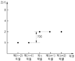
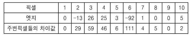
엣지 계산부(200)는 각 픽셀의 엣지를 계산한다. 여기서, 엣지는 소정 픽셀의 값과 소정 픽셀의 주변에 마련된 주변 픽셀의 값 간 차이값을 말한다. 도 7을 예를 들어 설명하면, 제n 펙셀의 엣지는 제(n-1) 픽셀의 값에 대한 제n 픽셀의 차이값을 말하고, 식별번호 700에 도시된 간격에 해당한다.The
제1 임계값 계산부(210)는 엣지 계산부(200)에서 계산된 각 픽셀의 엣지에 기 설정된 제1 값을 제산하여 제1 임계값을 계산한다.The first threshold
범위 결정부(220)는 제1 임계값 계산부(210)에서 계산된 제1 임계값을 이용하여 오차 계산부(110)에서 계산된 오차 가운데 부호화할 범위를 결정한다. 범위 결정부(220)에서 제1 임계값을 이용하여 오차 가운데 부호화할 범위를 결정하는 실시예로 다음 기재된 두 가지가 있을 수 있다.The
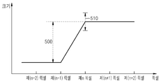
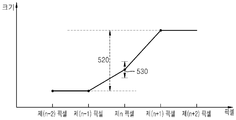
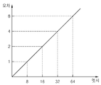
첫째, 오차 계산부(110)에서 계산된 오차 가운데 제1 임계값에 포함되지 않는 값만 부호화하는 범위로 결정한다. 도 5a를 예를 들어 설명하면, 엣지 계산부(200)에서는 제n 펙셀의 엣지로 식별번호 500에 해당하는 간격을 계산하고, 제1 임계값 계산부(210)에서는 도 6에 도시된 그래프와 같이 제1 임계값을 제산하는 값으로 '8'이 기 설정되면 식별번호 500에 해당하는 간격에 '8'을 제산하여 제1 임계값을 계산하며, 범위 결정부(220)는 제n 픽셀의 값에 대하여 제1 임계값에 해당하는 오차를 허용하는 식별번호 510에 해당하는 범위를 결정한다. First, a range in which only the values not included in the first threshold value among the errors calculated by the
도 9a에 도시된 제4 픽셀을 예를 들어 엣지 계산부(200)에서 제4 픽셀의 엣지로 '25'가 계산되었다고 가정하고 설명하기로 한다. 단, 도 9a 및 9b의 실시예에서는 예측부(100)에서 참조 픽셀을 예측함에 있어서 주변 픽셀을 이용하는 것이 일반적이므로 엣지와 오차는 같다고 가정한다. 제1 임계값 계산부(210)에서는 제4 픽셀의 엣지인 '25'에 기 설정된 제1 값인 '8'을 제산하여 제1 임계값인 '3.125'를 계산하며, 범위 결정부(220)는 제1 임계값인 '3.125' 이하에 해당하는 하위 2비트를 부호화하지 않는 범위로 결정하고 제1 임계값인 '3.125' 이상에 해당하는 상위 3비트를 부호화하는 범위로 결정한다. 이에 따라 범위 결정부(220)는 제4 픽셀의 오차인 '25'에 해당하는 '11001' 가운데 상위 3비트인 '110'만 부호화하는 범위로 결정하고 하위 2비트인 '01'는 부호화하지 않는 범위로 결정한다.Assume that the fourth pixel shown in FIG. 9A, for example, the
둘째, 오차 계산부(110)에서 계산된 오차 가운데 제1 임계값에 포함되지 않는 범위 및 부호화기에서 부호화되지 않은 오류값을 복호화기에서 복원하는 알고리즘를 고려하여 부호화하는 범위로 결정한다. 부호화기에서 부호화되지 않는 오류값은 복호화기에서 기 설정된 알고리즘에 의하여 복원된다. 여기서 기 설정된 알고리즘의 예로 부호화기에서 부호화되지 않은 오류값의 범위 내에서 가능한 모든 수의 기대값, 평균값 및 중간값으로 복호화단에서 복원할 수 있으며, 각 오류값에 대응하는 복원될 값을 테이블로 기 저장하여 독출함으로써 복원할 수 있다. 만일 부호화기에서 부호화되지 않은 오류값의 범위 내에서 가능한 모든 수의 중간값으로 복호화단에서 복원할 경우 제1 임계값에 의해 결정된 부호화하지 않을 하위 비트를 1비트 증가시킬 수 있으므로 제1 임계값에 의해 결정된 부호화할 상위 비트를 1비트 감소시킬 수 있다. Second, a range not to be included in the first threshold value among the errors calculated by the
예를 들어, 첫번째 방식에서 설명한 예인 도 9a에 도시된 제4 픽셀의 경우 제1 임계값 계산부(210)에서 계산된 제1 임계값인 '3.125'를 기준으로 하여 범위 결정부(220)는 제1 임계값인 '3.125' 이하에 해당하는 하위 2비트를 부호화하지 않는 범위로 결정하고 제1 임계값인 '3.125' 이상에 해당하는 상위 3비트를 부호화하는 범위로 결정한다. 이에 따라 범위 결정부(220)는 제4 픽셀의 오차인 '25'에 해당하는 '11001' 가운데 상위 3비트인 '110'만 부호화하는 범위로 결정하고 하위 2비트인 '01'는 부호화하지 않는 범위로 결정한다.For example, in the case of the fourth pixel shown in FIG. 9A, which is the example described in the first method, the
그러나 두번째 방식에 따라 부호화기에서 부호화되지 않은 오류값의 범위 내에서 가능한 모든 수의 중간 값으로 복호화단에서 복원할 경우 상위 비트 가운데 1비트를 더 부호화하지 않고 상위 2비트인 '11'만 부호화하는 범위로 결정하고 하위 3비트는 부호화하지 않는 범위로 결정한다. 이 경우도 부호화기에서 전송하지 않은 하위 3비트로 표현할 수 있는 '000' 내지 '111'의 중간값인 '100'로 복호화기에서 하위 3비트를 복원하므로 부호화단에서 전송된 상위 2비트인 '11'과 합성하여 최종적으로 '11100'으로 복원한다. 이렇게 복원된 '11100'은 제4 픽셀의 오차인 '11001'와 '11' 밖에 차이가 나지 않으므로 제1 임계값에 포함된다. 그러므로 제1 임계값으로 결정된 상위 비트 가운데 1비트를 덜 부호화하는 범위로 결정하더라고 복호화기에서 임계값 범위 내에 해당하는 픽셀의 값으로 복원되기 때문에 인간의 시감 특성상 인지할 수 없다.However, according to the second scheme, when decoding is performed at the decoding end with all possible intermediate values within the range of error values not encoded in the encoder, one bit of the upper bits is not further encoded but only the upper two bits '11' And the lower 3 bits are determined as a range not to be encoded. In this case, too, the lower 3 bits are recovered from the decoder to '100' which is an intermediate value of '000' to '111' which can be represented by lower 3 bits not transmitted by the encoder. And finally restored to '11100'. The reconstructed '11100' is included in the first threshold since there is no difference between '11001' and '11', which are errors of the fourth pixel. Therefore, even though one bit among the upper bits determined as the first threshold value is determined as a range for encoding less, the decoder can not recognize the human sensibility because it is restored to the value of the pixel within the threshold value range in the decoder.
이와 동일한 방식으로 도 9a에 도시된 제1 내지 제3 픽셀 및 제5 내지 제10 픽셀에 대한 엣지로 제1 임계값을 계산함으로써 도 9b에 도시된 바와 같이 점선 보다 상위 비트에 해당하는 비트를 부호화할 범위로 결정할 수 있다. 도 9a 및 9b의 실시예는 제1값이 '8'로 기 설정하여 가정하였으므로 상위 2비트만 부호화할 범위로 결정할 수 있다.In the same manner, by calculating the first threshold value with the edges for the first through third pixels and the fifth through tenth pixels shown in FIG. 9A, bits corresponding to higher bits than the dotted line are encoded Can be determined as the range to do. Since the embodiment of FIGS. 9A and 9B assumes that the first value is set to '8' in advance, it can be determined that only the upper two bits are to be encoded.
다시 말해, 소정 픽셀의 엣지와 참조 픽셀의 오차가 같고 제1 임계값을 제산하는 기 설정된 값이 '8'이라고 가정하면, 첫번째 방식에 의해 구현할 경우 상위 3비트만 부호화하는 범위로 결정하고, 두번째 방식에 의해 구현할 경우 부호화기에서 부호화되지 않은 하위 비트를 복호화기에서 복원할 때 중간값을 가산하는 방식 의 알고리즘을 취하면 상위 2비트만 부호화하는 범위로 결정하면 한다. 그러나 여기서 기 설정된 값인 '8'에 한정하여 실시하는 것은 아니며 디스플레이 특성과 같은 실시 환경에 따라 다른 값을 기 설정하여 실시할 수도 있다.In other words, if the error of the reference pixel and the edge of a certain pixel are the same and a preset value for dividing the first threshold is 8, the range is determined to be the range of encoding only the upper 3 bits when implemented by the first method, Scheme, when the decoder decodes lower bits that are not encoded by the encoder, an algorithm of a method of adding an intermediate value is used. However, the present invention is not limited to the preset value '8', but may be performed by setting other values according to the operating environment such as display characteristics.
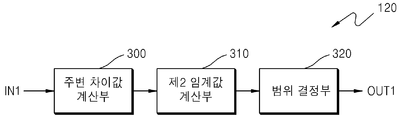
도 3은 소정 픽셀의 주변에 마련된 주변 픽셀들을 이용하여 오차 계산부(110)에서 계산된 오차 가운데 부호화할 범위를 결정하는 일 실시예를 블록도로 도시한 것으로서, 부호화범위 결정부(120)는 주변차이값 계산부(300), 제2 임계값 계산부(310) 및 범위 결정부(320)를 포함하여 이루어진다.FIG. 3 is a block diagram of an embodiment for determining a range to be coded based on errors calculated by the
주변차이값 계산부(300)는 각 픽셀의 주변에 마련된 주변 픽셀들 사이의 차이값을 계산한다. 도 8을 예를 들어 설명하면, 제n 픽셀의 주변 픽셀들 사이의 차이값은 제n 픽셀의 주변에 마련된 제(n-1) 픽셀과 제(n+1) 픽셀 사이의 차이값을 말하고, 식별번호 800에 도시된 간격에 해당한다.The neighboring difference
제2 임계값 계산부(310)는 주변차이값 계산부(300)에서 계산된 각 픽셀의 주변 픽셀들 사이의 차이값에 기 설정된 제2 값을 제산하여 제2 임계값을 계산한다. The second threshold
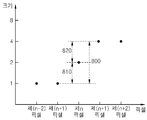
여기서, 기 설정된 값은 도 2에 기술된 제1 값과 서로 상이할 수 있다. 특정 픽셀의 주변에 마련된 주변 픽셀들 사이의 차이값은 특정 픽셀과 주변 픽셀 사이의 최대 차이값에 '2'를 승산한 값 이상에 해당한다. 이러한 관계를 도 8을 이용하여 설명하면 제n 픽셀의 주변 픽셀에는 제(n-1) 픽셀과 제(n+1) 픽셀이 있다. 제n 픽셀과 그 주변 픽셀 중 하나인 제(n-1) 픽셀의 차이값인 제1 엣지는 식별번호 810에 해당하는 값이고, 제n 픽셀과 나머지 주변 픽셀인 제(n+1) 픽셀의 차이값인 제2 엣지는 식별번호 820에 해당한다. 이들 관계를 수학식으로 기재하면 다음과 같다.Here, the preset value may be different from the first value described in FIG. The difference value between neighboring pixels provided in the vicinity of a specific pixel corresponds to a value obtained by multiplying the maximum difference value between the specific pixel and the neighboring pixel by " 2 ". Referring to FIG. 8, the neighboring pixels of the n-th pixel include (n-1) th and (n + 1) th pixels. The first edge, which is the difference between the (n-1) th pixel and the (n + 1) th pixel, is a value corresponding to the identification number 810, The second edge, which is the difference value, corresponds to the identification number 820. These relations are expressed in the following equations.
[수학식 1][Equation 1]
![]()
![]()
여기서, "edge1"은 제1 엣지이고, "edge2"는 제2 엣지이며, "neighbor"는 주변 픽셀들 사이의 차이값을 말한다.Here, "edge1" is the first edge, "edge2" is the second edge, and "neighbor"
엣지와 주변 픽셀들 사이의 차이값이 수학식 1과 같은 관계를 갖기 때문에 엣지가 주변 픽셀들 사이의 차이값과 같다고 가정하고 제1 값에 '2'를 제산한 값을 제2 값으로 기 설정할 수 있다.Since the difference value between the edge and the neighboring pixels has the relationship as expressed by
범위 결정부(320)는 제2 임계값 계산부(310)에서 계산된 제2 임계값을 이용하여 오차 계산부(110)에서 계산된 오차 가운데 부호화할 범위를 결정한다. 범위 결정부(320)에서 제2 임계값을 이용하여 오차 가운데 부호화할 범위를 결정하는 실시예로 다음 기재된 두 가지가 있을 수 있다.The
첫째, 오차 계산부(110)에서 계산된 오차 가운데 제2 임계값에 포함되지 않는 값만 부호화하는 범위로 결정한다. 도 5b를 예를 들어 설명하면, 주변차이값 계산부(300)에서는 제n 펙셀의 주변 픽셀들에 해당하는 제(n-1) 픽셀과 제(n+1) 픽셀의 차이값인 식별번호 520에 해당하는 간격을 계산하고, 제2 임계값 계산부(310)에서는 제2 임계값을 제산하는 제2 값으로 '16'이 기 설정되면 식별번호 520에 해당하는 간격에 '16'을 제산하여 제2 임계값을 계산하며, 범위 결정부(320)는 제n 픽셀의 값에 대하여 제2 임계값에 포함되는 오차를 허용한다. First, it is determined that only a value that is not included in the second threshold among the errors calculated by the
도 9a에 도시된 제4 픽셀을 예를 들어 주변차이값 계산부(300)에서 제4 픽셀의 주변 픽셀들의 차이값으로 '46'이 계산되었다고 가정하고 설명한다. 단, 도 9a 및 9b의 실시예에서는 예측부(100)에서 참조 픽셀을 예측함에 있어서 주변 픽셀을 이용하는 것이 일반적이므로 엣지와 오차는 같다고 가정한다. 제2 임계값 계산부(310)에서는 제4 픽셀의 주변 픽셀들의 차이값인 '46'에 '16'을 제산하여 제2 임계값인 '2.875'를 계산하며, 범위 결정부(320)는 제2 임계값인 '2.875' 이하에 해당하는 하위 2비트를 부호화하지 않는 범위로 결정하고 제2 임계값인 '2.875' 이상에 해당하는 상위 3비트를 부호화하는 범위로 결정한다. 이에 따라 범위 결정부(320)는 제4 픽셀의 오차인 '25'에 해당하는 '11001' 가운데 상위 3비트인 '110'만 부호화하는 범위로 결정하고 하위 2비트인 '01'는 부호화하지 않는 범위로 결정한다.Assuming that the fourth pixel shown in FIG. 9A, for example, '46' is calculated as the difference value of the neighboring pixels of the fourth pixel in the neighboring
둘째, 오차 계산부(110)에서 계산된 오차 가운데 제2 임계값에 포함되지 않는 범위 및 부호화기에서 부호화되지 않은 오류값을 복호화기에서 복원하는 알고리즘을 고려하여 부호화하는 범위로 결정한다. 부호화기에서 부호화되지 않는 오류값은 복호화기에서 기 설정된 알고리즘에 의하여 복원된다. 여기서 기 설정된 알고리즘의 예로 부호화기에서 부호화되지 않은 오류값의 범위 내에서 가능한 모든 수의 기대값, 평균값 및 중간값으로 복호화단에서 복원할 수 있으며, 각 오류값에 대응하는 복원될 값을 테이블로 기 저장하여 독출함으로써 복원할 수 있다. 만일 부호화기에서 부호화되지 않은 오류값의 범위 내에서 가능한 모든 수의 중간값으로 복호화단에서 복원할 경우 제2 임계값에 의해 결정된 부호화하지 않을 하위 비트를 2비트 증가시킬 수 있으므로 제2 임계값에 의해 결정된 부호화할 상위 비트를 1비트 감소시킬 수 있다. 이와 같은 방식으로 도 9a에 도시된 제1 내지 제3 픽셀 및 제5 내지 제10 픽셀에 대한 주변 픽셀들의 차이값으로 제2 임계값을 계산함으로써 도 9b에 도시된 바와 같이 굵은 실선 보다 상위 비트에 해당하는 비트를 부호화할 범위로 결정할 수 있다. 도 9a 및 9b의 실시예는 제2 값이 '16'으로 기 설정하여 가정하였으므로 상위 3비트만 부호화할 범위로 결정할 수 있다.Second, a range that is not included in the second threshold value among the errors calculated by the
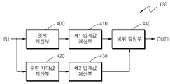
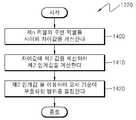
도 4는 소정 픽셀의 엣지 또는 소정 픽셀의 주변에 마련된 주변 픽셀들의 차이값을 이용하여 오차 계산부(110)에서 계산된 오차 가운데 부호화할 범위를 결정하는 일 실시예를 블록도로 도시한 것으로서, 부호화범위 결정부(120)는 엣지 계산부(400), 제1 임계값 계산부(410), 주변차이값 계산부(420), 제2 임계값 계산부(430) 및 범위 결정부(440)를 포함하여 이루어진다.FIG. 4 is a block diagram of an embodiment for determining a range to be coded based on the error calculated by the
엣지 계산부(400)는 각 픽셀의 엣지를 계산한다. 여기서, 엣지는 소정 픽셀의 값과 소정 픽셀의 주변에 마련된 주변 픽셀의 값 간 차이값을 말한다. 도 7을 예를 들어 설명하면, 제n 펙셀의 엣지는 제(n-1) 픽셀의 값에 대한 제n 픽셀의 차이값을 말하고, 식별번호 700에 도시된 간격에 해당한다.The
제1 임계값 계산부(410)는 엣지 계산부(400)에서 계산된 각 픽셀의 엣지에 기 설정된 제1 값을 제산하여 제1 임계값을 계산한다.The first threshold
주변차이값 계산부(420)는 각 픽셀의 주변에 마련된 주변 픽셀들 사이의 차이값을 계산한다. 도 8을 예를 들어 설명하면, 제n 픽셀의 주변 픽셀들 사이의 차 이값은 제n 픽셀의 주변에 마련된 제(n-1) 픽셀과 제(n+1) 픽셀 사이의 차이값을 말하고, 식별번호 800에 도시된 간격에 해당한다.The peripheral difference
제2 임계값 계산부(430)는 주변차이값 계산부(420)에서 계산된 각 픽셀의 주변 픽셀들 사이의 차이값에 기 설정된 제2 값을 제산하여 제2 임계값을 계산한다. 여기서, 기 설정된 값은 도 2에 기술된 제1 값과 서로 상이할 수 있다. 특정 픽셀의 주변에 마련된 주변 픽셀들 사이의 차이값은 특정 픽셀과 주변 픽셀 사이의 최대 차이값에 '2'를 승산한 값 이상에 해당한다. 이러한 관계를 도 8을 이용하여 설명하면 제n 픽셀의 주변 픽셀에는 제(n-1) 픽셀과 제(n+1) 픽셀이 있다. 제n 픽셀과 그 주변 픽셀 중 하나인 제(n-1) 픽셀의 차이값인 제1 엣지는 식별번호 810에 해당하는 값이고, 제n 픽셀과 나머지 주변 픽셀인 제(n+1) 픽셀의 차이값인 제2 엣지는 식별번호 820에 해당한다. 이들 관계를 수학식으로 기재하면 다음과 같다.The second threshold
[수학식 2]&Quot; (2) "
![]()
![]()
여기서, "edge1"은 제1 엣지이고, "edge2"는 제2 엣지이며, "neighbor"는 주변 픽셀들 사이의 차이값을 말한다.Here, "edge1" is the first edge, "edge2" is the second edge, and "neighbor"
엣지와 주변 픽셀들 사이의 차이값이 수학식 2과 같은 관계를 갖기 때문에 엣지가 주변 픽셀들 사이의 차이값과 같다고 가정하고 제1 값에 '2'를 제산한 값을 제2 값으로 기 설정할 수 있다.Since the difference value between the edge and the neighboring pixels has the relationship as shown in
범위 결정부(440)는 제1 임계값 계산부(410)에서 계산된 제1 임계값과 제2 임계값 계산부(430)에서 계산된 제2 임계값 가운데 가장 큰 임계값을 선택하고, 가장 큰 임계값을 이용하여 오차 계산부(110)에서 계산된 오차 가운데 부호화할 범위를 결정한다. 만일 제1 임계값이 제2 임계값 보다 크다면, 도 2에 개시된 범위 결정부(220)와 동일한 방식으로 오차 계산부(110)에서 계산된 오차 가운데 부호화할 범위를 결정하고, 만일 제2 임계값이 제1 임계값 보다 크다면, 도 3에 개시된 범위 결정부(320)와 동일한 방식으로 오차 계산부(110)에서 계산된 오차 가운데 부호화할 범위를 결정한다. The
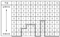
도 9a 및 9b는 범위 결정부(440)에서 범위를 결정하는 실시예를 테이블로 도시한 것이다. 도 9a는 제1 내지 제10 픽셀의 엣지와 제1 내지 제10 픽셀의 주변 픽셀들의 차이값을 테이블로 도시한 것이고, 도 9b는 제1 내지 제10 픽셀의 오차를 상위 비트부터 하위 비트 순으로 비트-플레인(bit-plane) 단위로 표현한 테이블을 도시한 것이다. 단, 도 9a 및 9b의 실시예에서는 예측부(100)에서 참조 픽셀을 예측함에 있어서 주변 픽셀을 이용하는 것이 일반적이므로 엣지와 오차는 같다고 가정한다.9A and 9B are tables showing an embodiment for determining the range in the
제1 임계값 계산부(410)에서 계산된 제1 임계값은 도 9b에서 점선으로 표시되어 있으며, 제2 임계값 계산부(430)에서 계산된 제2 임계값은 도 9b에서 실선으로 표시되어 있다. 범위 결정부(440)는 점선과 실선 가운데 더 큰 값을 임계값으로 결정하고 결정된 임계값 보다 상위 비트에 마련된 오차의 비트-플레인을 부호화하는 범위로 결정한다.The first threshold value calculated by the first threshold
다시 도 1에 도시된 실시예를 설명하면, 부호화부(130)는 부호화범위 결정 부(120)에서 결정된 범위에 해당하는 오차 계산부(110)에서 계산된 오차만 부호화한다. 보다 상세하게 말하면, 부호화부(130)는 부호화범위 결정부(120)에서 부호화하기로 결정한 상위 비트에 해당하는 오차 계산부(110)에서 계산된 오차만 부호화하여 비트스트림을 생성함으로써 출력단자 OUT을 통해 출력한다.1, the
도 12는 본 발명에 의한 시감 특성을 이용한 영상 부호화 방법에 대한 일 실시예를 흐름도로 도시한 것이다.FIG. 12 is a flowchart illustrating an image encoding method using a spectral characteristic according to the present invention.
먼저, 영상을 구성하는 픽셀들을 입력받아 기 설정된 방식에 따라 제n 픽셀에 대응하는 참조 픽셀의 값을 예측한다(제1200단계). 도 10은 제1200단계에서 소정 픽셀의 값을 예측하는 일 실시예를 도시한 개념도이다. 도 10에서는 소정 픽셀에 대하여 상 방향, 좌 방향 및 좌상 방향에 마련된 픽셀들의 값을 이용하여 소정 픽셀의 값을 예측할 수 있다. 제1200단계에서 참조 픽셀의 값을 예측하는 데 이용하는 기 설정된 방식의 일 실시예로 엣지 검출법(edge detecting method)을 사용하여 예측할 수 있다. 이러한 엣지 검출법으로 IEEE Trans. On Consumer Electronics, Vol 47, No.3, 2001, pp466-476 에 있는 "Two low cost algorithms for improved diagonal edge detection in JPEG-LS" 에 개시된 방법을 사용할 수 있다. 엣지 검출법을 이용하여 소정 픽셀 'x'의 값을 예측하는 일 실시예를 도 11을 이용하여 설명하기로 한다. 픽셀 'x'에 대한 에지 검출법의 알고리즘은 다음과 같다.First, the pixels constituting the image are input and a value of a reference pixel corresponding to the n-th pixel is predicted according to a predetermined method (operation 1200). FIG. 10 is a conceptual diagram illustrating an embodiment for predicting a value of a predetermined pixel in
if (c >= max(a,b)) P = min(a,b);if (c > = max (a, b)) P = min (a, b);
else{ else {
if (c <= min(a,b)) P = max(a,b);if (c < = min (a, b)) P = max (a, b);
else P = a+b-c;else P = a + b-c;
}}
여기서, 'P'는 'x' 픽셀에 대응하는 참조 픽셀의 값이며, 'a'는 좌 방향에 위치한 픽셀의 값이고, 'b'는 상 방향에 위치한 픽셀의 값이며, 'c'는 좌상 방향에 위치한 픽셀의 값이다.Here, 'P' is the value of the reference pixel corresponding to the 'x' pixel, 'a' is the value of the pixel located in the left direction, 'b' is the value of the pixel located in the upward direction, 'c' Lt; RTI ID = 0.0 > direction.
이 알고리즘에 의하면, 참조 픽셀의 값 'P'는 엣지(edge)가 수평 방향인지 수직 방향인지 여부와 'a' 와 'b' 중에 큰 값이 무엇인지에 따라 결정된다. 만일 'a' 및 'b' 가운데 더 큰 값 보다 'c'가 더 크거나 같다고 가정하면, 'a' 및 'b' 가운데 더 작은 값이 'a'일 경우 수평 방향의 엣지를 가지며 참조 픽셀의 값 'P'는 'a'로 결정되고, 'a' 및 'b' 가운데 더 작은 값이 'b'일 경우 수직 방향의 에지를 가지며 참조 픽셀의 값 'P'는 'b'로 결정된다. 반면에 'a' 및 'b' 가운데 더 작은 값이 'c' 더 크거나 같다고 가정하면, 'a' 및 'b' 가운데 더 큰 값이 'a'일 경우 수평 방향의 엣지를 가지며 참조 픽셀의 값 'P'는 'a'로 결정되고, 'a' 및 'b' 가운데 더 큰 값이 'b'일 경우 수직 방향의 엣지를 가지며 참조 픽셀의 값 'P'는 'b'로 결정된다. 또한, 'c'가 'a' 및 'b' 가운데 더 작은 값 보다 크고 'a' 및 'b' 가운데 더 큰 값 보다 작다고 가정하면, 엣지의 방향을 판정하기 어려우므로 참조 픽셀의 값 'P'는 'a', 'b', 'c' 모두를 고려하여 'a'에 'b'를 가산하고 'c'를 감산한 값으로 결정한다.According to this algorithm, the value 'P' of the reference pixel is determined according to whether the edge is horizontal or vertical and what is a large value between 'a' and 'b'. Assuming that 'c' is greater than or equal to the larger of 'a' and 'b', if the smaller of 'a' and 'b' is 'a' The value 'P' is determined as 'a', and if the smaller value of 'a' and 'b' is 'b', the edge has a vertical edge and the reference pixel value 'P' is determined as 'b'. On the other hand, assuming that the smaller value of 'a' and 'b' is greater than or equal to 'c', if the larger of 'a' and 'b' is 'a' The value 'P' is determined as 'a', and when a larger value of 'a' and 'b' is 'b', the edge has a vertical direction and the reference pixel value 'P' is determined as 'b'. Also, assuming that 'c' is larger than a smaller value of 'a' and 'b' and smaller than a larger value of 'a' and 'b', it is difficult to determine the direction of the edge, Is determined by adding 'b' to 'a' and subtracting 'c', considering both 'a', 'b' and 'c'.
제1200단계에서 제n 픽셀에 대응하여 예측된 참조 픽셀의 값과 제n 픽셀의 값에 대한 오차(error)를 계산한다(제1210단계).In
제1210단계에서 계산된 제n 픽셀의 오차 가운데 부호화할 범위를 결정한다(제1220단계). 제1220단계에서 범위를 결정함에 있어서, 인간의 시감 특성상 인지할 수 있는 범위를 판단할 수 있는 기 설정된 방식을 이용한다. 다시 말하면, 제1220단계에서는 제1210단계에서 계산된 오차 가운데 인간의 시감 특성상 인지할 수 있는 상위 비트에 해당하는 값과 인간의 시감 특성상 인지할 수 없는 하위 비트에 해당하는 값을 구별한다.In
이러한 제1220단계의 실시예로 도 13, 14 및 15가 있다.13, 14, and 15 are examples of this
도 13은 제n 픽셀의 엣지를 이용하여 제1210단계에서 계산된 제n 픽셀의 오차 가운데 부호화할 범위를 결정하는 일 실시예를 흐름도로 도시한 것이다.FIG. 13 is a flowchart illustrating an embodiment of determining a range to be coded based on the error of the n-th pixel calculated in
먼저, 제n 픽셀의 엣지를 계산한다(제1300단계). 여기서, 엣지는 소정 픽셀의 값과 소정 픽셀의 주변에 마련된 주변 픽셀의 값 간 차이값을 말한다. 도 7을 예를 들어 설명하면, 제n 펙셀의 엣지는 제(n-1) 픽셀의 값에 대한 제n 픽셀의 차이값을 말하고, 식별번호 700에 도시된 간격에 해당한다.First, the edge of the n-th pixel is calculated (operation 1300). Here, the edge refers to a difference value between a value of a predetermined pixel and a value of a peripheral pixel provided in the periphery of the predetermined pixel. 7, the edge of the n-th pixel is the difference value of the n-th pixel with respect to the value of the (n-1) pixel, and corresponds to the interval shown in the
제1300단계에서 계산된 제n 픽셀의 엣지에 기 설정된 제1 값을 제산하여 제1 임계값을 계산한다(제1310단계).In operation 1310, the first threshold value is calculated by dividing the first value preset in the edge of the n-th pixel calculated in
제1310단계에서 계산된 제n 픽셀의 제1 임계값을 이용하여 제1210단계에서 계산된 제n 픽셀의 오차 가운데 부호화할 범위를 결정한다(제1320단계). 제1320단계에서 제1 임계값을 이용하여 오차 가운데 부호화할 범위를 결정하는 실시예로 다음 기재된 두 가지가 있을 수 있다.In
첫째, 제1210단계에서 계산된 오차 가운데 제1 임계값에 포함되지 않는 값만 부호화하는 범위로 결정한다. 도 5a를 예를 들어 설명하면, 제1300단계에서는 제n 펙셀의 엣지로 식별번호 500에 해당하는 간격을 계산하고, 제1310단계에서는 도 6에 도시된 그래프와 같이 제1 임계값을 제산하는 값으로 '8'이 기 설정되면 식별번호 500에 해당하는 간격에 '8'을 제산하여 제1 임계값을 계산하며, 제1320단계에서는 제n 픽셀의 값에 대하여 제1 임계값에 해당하는 오차를 허용하는 식별번호 510에 해당하는 범위를 결정한다. First, a range in which only the values not included in the first threshold value among the errors calculated in
도 9a에 도시된 제4 픽셀을 예를 들어 제1300단계에서 제4 픽셀의 엣지로 '25'가 계산되었다고 가정하고 설명하기로 한다. 단, 도 9a 및 9b의 실시예에서는 제1200단계에서 참조 픽셀을 예측함에 있어서 주변 픽셀을 이용하는 것이 일반적이므로 엣지와 오차는 같다고 가정한다. 제1310단계에서는 제4 픽셀의 엣지인 '25'에 기 설정된 제1 값인 '8'을 제산하여 제1 임계값인 '3.125'를 계산하며, 제1320단계에서는 제1 임계값인 '3.125' 이하에 해당하는 하위 2비트를 부호화하지 않는 범위로 결정하고 제1 임계값인 '3.125' 이상에 해당하는 상위 3비트를 부호화하는 범위로 결정한다. 이에 따라 제1320단계에서는 제4 픽셀의 오차인 '25'에 해당하는 '11001' 가운데 상위 3비트인 '110'만 부호화하는 범위로 결정하고 하위 2비트인 '01'는 부호화하지 않는 범위로 결정한다.Assume that the fourth pixel shown in FIG. 9A, for example, in
둘째, 제1210단계에서 계산된 오차 가운데 제1 임계값에 포함되지 않는 범위 및 부호화기에서 부호화되지 않은 오류값을 복호화기에서 복원하는 알고리즘를 고려하여 부호화하는 범위로 결정한다. 부호화기에서 부호화되지 않는 오류값은 복 호화기에서 기 설정된 알고리즘에 의하여 복원된다. 여기서 기 설정된 알고리즘의 예로 부호화기에서 부호화되지 않은 오류값의 범위 내에서 가능한 모든 수의 기대값, 평균값 및 중간값으로 복호화단에서 복원할 수 있으며, 각 오류값에 대응하는 복원될 값을 테이블로 기 저장하여 독출함으로써 복원할 수 있다. 만일 부호화기에서 부호화되지 않은 오류값의 범위 내에서 가능한 모든 수의 중간값으로 복호화단에서 복원할 경우 제1 임계값에 의해 결정된 부호화하지 않을 하위 비트를 1비트 증가시킬 수 있으므로 제1 임계값에 의해 결정된 부호화할 상위 비트를 1비트 감소시킬 수 있다. Second, a range to be included in the first threshold value among the errors calculated in
예를 들어, 첫번째 방식에서 설명한 예인 도 9a에 도시된 제4 픽셀의 경우 제1310단계에서 계산된 제1 임계값인 '3.125'를 기준으로 하여 제1320단계에서는 제1 임계값인 '3.125' 이하에 해당하는 하위 2비트를 부호화하지 않는 범위로 결정하고 제1 임계값인 '3.125' 이상에 해당하는 상위 3비트를 부호화하는 범위로 결정한다. 이에 따라 제1320단계에서는 제4 픽셀의 오차인 '25'에 해당하는 '11001' 가운데 상위 3비트인 '110'만 부호화하는 범위로 결정하고 하위 2비트인 '01'는 부호화하지 않는 범위로 결정한다.For example, in the case of the fourth pixel shown in FIG. 9A, which is the example described in the first method, the first threshold value '3.125' calculated in step 1310 is used as a reference, and in
그러나 두번째 방식에 따라 부호화기에서 부호화되지 않은 오류값의 범위 내에서 가능한 모든 수의 중간 값으로 복호화단에서 복원할 경우 상위 비트 가운데 1비트를 더 부호화하지 않고 상위 2비트인 '11'만 부호화하는 범위로 결정하고 하위 3비트는 부호화하지 않는 범위로 결정한다. 이 경우도 부호화기에서 전송하지 않은 하위 3비트로 표현할 수 있는 '000' 내지 '111'의 중간값인 '100'로 복호화기에 서 하위 3비트를 복원하므로 부호화단에서 전송된 상위 2비트인 '11'과 합성하여 최종적으로 '11100'으로 복원한다. 이렇게 복원된 '11100'은 제4 픽셀의 오차인 '11001'와 '11' 밖에 차이가 나지 않으므로 제1 임계값에 포함된다. 그러므로 제1 임계값으로 결정된 상위 비트 가운데 1비트를 덜 부호화하는 범위로 결정하더라고 복호화기에서 임계값 범위 내에 해당하는 픽셀의 값으로 복원되기 때문에 인간의 시감 특성상 인지할 수 없다.However, according to the second scheme, when decoding is performed at the decoding end with all possible intermediate values within the range of error values not encoded in the encoder, one bit of the upper bits is not further encoded but only the upper two bits '11' And the lower 3 bits are determined as a range not to be encoded. In this case, too, the lower 3 bits are recovered from the decoders to '100', which is an intermediate value of '000' to '111' which can be expressed by the lower 3 bits not transmitted by the encoder, And finally restored to '11100'. The reconstructed '11100' is included in the first threshold since there is no difference between '11001' and '11', which are errors of the fourth pixel. Therefore, even though one bit among the upper bits determined as the first threshold value is determined as a range for encoding less, the decoder can not recognize the human sensibility because it is restored to the value of the pixel within the threshold value range in the decoder.
이와 동일한 방식으로 도 9a에 도시된 제1 내지 제3 픽셀 및 제5 내지 제10 픽셀에 대한 엣지로 제1 임계값을 계산함으로써 도 9b에 도시된 바와 같이 점선 보다 상위 비트에 해당하는 비트를 부호화할 범위로 결정할 수 있다. 도 9a 및 9b의 실시예는 제1값이 '8'로 기 설정하여 가정하였으므로 상위 2비트만 부호화할 범위로 결정할 수 있다.In the same manner, by calculating the first threshold value with the edges for the first through third pixels and the fifth through tenth pixels shown in FIG. 9A, bits corresponding to higher bits than the dotted line are encoded Can be determined as the range to do. Since the embodiment of FIGS. 9A and 9B assumes that the first value is set to '8' in advance, it can be determined that only the upper two bits are to be encoded.
다시 말해, 소정 픽셀의 엣지와 참조 픽셀의 오차가 같고 제1 임계값을 제산하는 기 설정된 값이 '8'이라고 가정하면, 첫번째 방식에 의해 구현할 경우 상위 3비트만 부호화하는 범위로 결정하고, 두번째 방식에 의해 구현할 경우 부호화기에서 부호화되지 않은 하위 비트를 복호화기에서 복원할 때 중간값을 가산하는 방식의 알고리즘을 취하면 상위 2비트만 부호화하는 범위로 결정하면 한다. 그러나 여기서 기 설정된 값인 '8'에 한정하여 실시하는 것은 아니며 디스플레이 특성과 같은 실시 환경에 따라 다른 값을 기 설정하여 실시할 수도 있다.In other words, if the error of the reference pixel and the edge of a certain pixel are the same and a preset value for dividing the first threshold is 8, the range is determined to be the range of encoding only the upper 3 bits when implemented by the first method, Scheme, when the decoder decodes lower bits that are not encoded by the encoder, an algorithm of a method of adding an intermediate value is used. However, the present invention is not limited to the preset value '8', but may be performed by setting other values according to the operating environment such as display characteristics.
도 14는 제n 픽셀의 주변에 마련된 주변 픽셀들을 이용하여 제1210단계에서 계산된 오차 가운데 부호화할 범위를 결정하는 일 실시예를 흐름도로 도시한 것이 다.FIG. 14 is a flowchart illustrating an example of determining a range to be coded based on the error calculated in
먼저, 제n 픽셀의 주변에 마련된 주변 픽셀들 사이의 차이값을 계산한다(제1400단계). 도 8을 예를 들어 설명하면, 제n 픽셀의 주변 픽셀들 사이의 차이값은 제n 픽셀의 주변에 마련된 제(n-1) 픽셀과 제(n+1) 픽셀 사이의 차이값을 말하고, 식별번호 800에 도시된 간격에 해당한다.First, a difference value between neighboring pixels provided around the nth pixel is calculated (operation 1400). 8, the difference value between neighboring pixels of the n-th pixel refers to a difference value between the (n-1) -th pixel and the (n + 1) -th pixel provided in the periphery of the n-th pixel, Corresponds to the interval shown in the
제1400단계에서 계산된 각 픽셀의 주변 픽셀들 사이의 차이값에 기 설정된 제2 값을 제산하여 제2 임계값을 계산한다(제1410단계). In
여기서, 기 설정된 값은 도 2에 기술된 제1 값과 서로 상이할 수 있다. 특정 픽셀의 주변에 마련된 주변 픽셀들 사이의 차이값은 특정 픽셀과 주변 픽셀 사이의 최대 차이값에 '2'를 승산한 값 이상에 해당한다. 이러한 관계를 도 8을 이용하여 설명하면 제n 픽셀의 주변 픽셀에는 제(n-1) 픽셀과 제(n+1) 픽셀이 있다. 제n 픽셀과 그 주변 픽셀 중 하나인 제(n-1) 픽셀의 차이값인 제1 엣지는 식별번호 810에 해당하는 값이고, 제n 픽셀과 나머지 주변 픽셀인 제(n+1) 픽셀의 차이값인 제2 엣지는 식별번호 820에 해당한다. 이들 관계를 수학식으로 기재하면 다음과 같다.Here, the preset value may be different from the first value described in FIG. The difference value between neighboring pixels provided in the vicinity of a specific pixel corresponds to a value obtained by multiplying the maximum difference value between the specific pixel and the neighboring pixel by " 2 ". Referring to FIG. 8, the neighboring pixels of the n-th pixel include (n-1) th and (n + 1) th pixels. The first edge, which is the difference between the (n-1) th pixel and the (n + 1) th pixel, is a value corresponding to the identification number 810, The second edge, which is the difference value, corresponds to the identification number 820. These relations are expressed in the following equations.
[수학식 3]&Quot; (3) "
![]()
![]()
여기서, "edge1"은 제1 엣지이고, "edge2"는 제2 엣지이며, "neighbor"는 주변 픽셀들 사이의 차이값을 말한다.Here, "edge1" is the first edge, "edge2" is the second edge, and "neighbor"
엣지와 주변 픽셀들 사이의 차이값이 수학식 1과 같은 관계를 갖기 때문에 엣지가 주변 픽셀들 사이의 차이값과 같다고 가정하고 제1 값에 '2'를 제산한 값을 제2 값으로 기 설정할 수 있다.Since the difference value between the edge and the neighboring pixels has the relationship as expressed by
제1410단계에서 계산된 제2 임계값을 이용하여 제1210단계에서 계산된 오차 가운데 부호화할 범위를 결정한다(제1420단계). 제1420단계에서 제2 임계값을 이용하여 오차 가운데 부호화할 범위를 결정하는 실시예로 다음 기재된 두 가지가 있을 수 있다.In
첫째, 제1410단계에서 계산된 오차 가운데 제2 임계값에 포함되지 않는 값만 부호화하는 범위로 결정한다. 도 5b를 예를 들어 설명하면, 제1400단계에서는 제n 펙셀의 주변 픽셀들에 해당하는 제(n-1) 픽셀과 제(n+1) 픽셀의 차이값인 식별번호 520에 해당하는 간격을 계산하고, 제1410단계에서는 제2 임계값을 제산하는 제2 값으로 '16'이 기 설정되면 식별번호 520에 해당하는 간격에 '16'을 제산하여 제2 임계값을 계산하며, 제1420단계에서는 제n 픽셀의 값에 대하여 제2 임계값에 포함되는 오차를 허용한다. First, a range in which only values that are not included in the second threshold value among the errors calculated in
도 9a에 도시된 제4 픽셀을 예를 들어 제1400단계에서 제4 픽셀의 주변 픽셀들의 차이값으로 '46'이 계산되었다고 가정하고 설명한다. 단, 도 9a 및 9b의 실시예에서는 제1200단계에서 참조 픽셀을 예측함에 있어서 주변 픽셀을 이용하는 것이 일반적이므로 엣지와 오차는 같다고 가정한다. 제1410단계에서는 제4 픽셀의 주변 픽셀들의 차이값인 '46'에 '16'을 제산하여 제2 임계값인 '2.875'를 계산하며, 제1420단계에서는 제2 임계값인 '2.875' 이하에 해당하는 하위 2비트를 부호화 하지 않는 범위로 결정하고 제2 임계값인 '2.875' 이상에 해당하는 상위 3비트를 부호화하는 범위로 결정한다. 이에 따라 제1420단계에서는 제4 픽셀의 오차인 '25'에 해당하는 '11001' 가운데 상위 3비트인 '110'만 부호화하는 범위로 결정하고 하위 2비트인 '01'는 부호화하지 않는 범위로 결정한다.For example, assuming that '46' is calculated as the difference value of the neighboring pixels of the fourth pixel in
둘째, 제1210단계에서 계산된 오차 가운데 제2 임계값에 포함되지 않는 범위 및 부호화기에서 부호화되지 않은 오류값을 복호화기에서 복원하는 알고리즘을 고려하여 부호화하는 범위로 결정한다. 부호화기에서 부호화되지 않는 오류값은 복호화기에서 기 설정된 알고리즘에 의하여 복원된다. 여기서 기 설정된 알고리즘의 예로 부호화기에서 부호화되지 않은 오류값의 범위 내에서 가능한 모든 수의 기대값, 평균값 및 중간값으로 복호화단에서 복원할 수 있으며, 각 오류값에 대응하는 복원될 값을 테이블로 기 저장하여 독출함으로써 복원할 수 있다. 만일 부호화기에서 부호화되지 않은 오류값의 범위 내에서 가능한 모든 수의 중간값으로 복호화단에서 복원할 경우 제2 임계값에 의해 결정된 부호화하지 않을 하위 비트를 2비트 증가시킬 수 있으므로 제2 임계값에 의해 결정된 부호화할 상위 비트를 1비트 감소시킬 수 있다. 이와 같은 방식으로 도 9a에 도시된 제1 내지 제3 픽셀 및 제5 내지 제10 픽셀에 대한 주변 픽셀들의 차이값으로 제2 임계값을 계산함으로써 도 9b에 도시된 바와 같이 굵은 실선 보다 상위 비트에 해당하는 비트를 부호화할 범위로 결정할 수 있다. 도 9a 및 9b의 실시예는 제2 값이 '16'으로 기 설정하여 가정하였으므로 상위 3비트만 부호화할 범위로 결정할 수 있다.Second, a range not to be included in the second threshold value among the errors calculated in
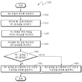
도 15는 제n 픽셀의 엣지 또는 제n 픽셀의 주변에 마련된 주변 픽셀들의 차 이값을 이용하여 제1210단계에서 계산된 오차 가운데 부호화할 범위를 결정하는 일 실시예를 흐름도로 도시한 것이다.FIG. 15 is a flowchart illustrating an embodiment of determining a range to be coded based on an error calculated in
먼저, 제n 픽셀의 엣지를 계산한다(제1500단계). 여기서, 엣지는 소정 픽셀의 값과 소정 픽셀의 주변에 마련된 주변 픽셀의 값 간 차이값을 말한다. 도 7을 예를 들어 설명하면, 제n 펙셀의 엣지는 제(n-1) 픽셀의 값에 대한 제n 픽셀의 차이값을 말하고, 식별번호 700에 도시된 간격에 해당한다.First, the edge of the n-th pixel is calculated (operation 1500). Here, the edge refers to a difference value between a value of a predetermined pixel and a value of a peripheral pixel provided in the periphery of the predetermined pixel. 7, the edge of the n-th pixel is the difference value of the n-th pixel with respect to the value of the (n-1) pixel, and corresponds to the interval shown in the
제1500단계에서 계산된 제n 픽셀의 엣지에 기 설정된 제1 값을 제산하여 제1 임계값을 계산한다(제1510단계).The first threshold value is calculated by dividing the first value preset in the edge of the n-th pixel calculated in operation 1500 (operation 1510).
제n 픽셀의 주변에 마련된 주변 픽셀들 사이의 차이값을 계산한다(제1520단계). 도 8을 예를 들어 설명하면, 제n 픽셀의 주변 픽셀들 사이의 차이값은 제n 픽셀의 주변에 마련된 제(n-1) 픽셀과 제(n+1) 픽셀 사이의 차이값을 말하고, 식별번호 800에 도시된 간격에 해당한다.A difference value between neighboring pixels provided around the nth pixel is calculated (operation 1520). 8, the difference value between neighboring pixels of the n-th pixel refers to a difference value between the (n-1) -th pixel and the (n + 1) -th pixel provided in the periphery of the n-th pixel, Corresponds to the interval shown in the
제1520단계에서 계산된 각 픽셀의 주변 픽셀들 사이의 차이값에 기 설정된 제2 값을 제산하여 제2 임계값을 계산한다(제1530단계). In
여기서, 기 설정된 값은 도 2에 기술된 제1 값과 서로 상이할 수 있다. 특정 픽셀의 주변에 마련된 주변 픽셀들 사이의 차이값은 특정 픽셀과 주변 픽셀 사이의 최대 차이값에 '2'를 승산한 값 이상에 해당한다. 이러한 관계를 도 8을 이용하여 설명하면 제n 픽셀의 주변 픽셀에는 제(n-1) 픽셀과 제(n+1) 픽셀이 있다. 제n 픽셀과 그 주변 픽셀 중 하나인 제(n-1) 픽셀의 차이값인 제1 엣지는 식별번호 810에 해당하는 값이고, 제n 픽셀과 나머지 주변 픽셀인 제(n+1) 픽셀의 차이값인 제2 엣지는 식별번호 820에 해당한다. 이들 관계를 수학식으로 기재하면 다음과 같다.Here, the preset value may be different from the first value described in FIG. The difference value between neighboring pixels provided in the vicinity of a specific pixel corresponds to a value obtained by multiplying the maximum difference value between the specific pixel and the neighboring pixel by " 2 ". Referring to FIG. 8, the neighboring pixels of the n-th pixel include (n-1) th and (n + 1) th pixels. The first edge, which is the difference between the (n-1) th pixel and the (n + 1) th pixel, is a value corresponding to the identification number 810, The second edge, which is the difference value, corresponds to the identification number 820. These relations are expressed in the following equations.
[수학식 4]&Quot; (4) "
![]()
![]()
여기서, "edge1"은 제1 엣지이고, "edge2"는 제2 엣지이며, "neighbor"는 주변 픽셀들 사이의 차이값을 말한다.Here, "edge1" is the first edge, "edge2" is the second edge, and "neighbor"
엣지와 주변 픽셀들 사이의 차이값이 수학식 2과 같은 관계를 갖기 때문에 엣지가 주변 픽셀들 사이의 차이값과 같다고 가정하고 제1 값에 '2'를 제산한 값을 제2 값으로 기 설정할 수 있다.Since the difference value between the edge and the neighboring pixels has the relationship as shown in
제1510단계에서 계산된 제1 임계값과 제1530단계에서 계산된 제2 임계값 가운데 어느 임계값이 더 큰지 여부를 판단한다(제1540단계). In
제1540단계에서 제1 임계값이 제2 임계값 보다 더 크다고 판단되면, 제1510단계에서 계산된 제1 임계값을 이용하여 제1210단계에서 계산된 오차 가운데 부호화할 범위를 결정한다(제1550단계). 제1550단계에서는 도 13의 제1320단계에서 개시된 실시예와 동일하게 실시할 수 있다.If it is determined in
제1540단계에서 제2 임계값이 제1 임계값 보다 더 크다고 판단되면, 제1510단계에서 계산된 제2 임계값을 이용하여 제1210단계에서 계산된 오차 가운데 부호화할 범위를 결정한다(제1560단계). 제1560단계에서는 도 14의 제1420단계에서 개시된 실시예와 동일하게 실시할 수 있다.If it is determined in
도 9a 및 9b는 제1540단계 내지 제1560단계에서 범위를 결정하는 실시예를 테이블로 도시한 것이다. 도 9a는 제1 내지 제10 픽셀의 엣지와 제1 내지 제10 픽셀의 주변 픽셀들의 차이값을 테이블로 도시한 것이고, 도 9b는 제1 내지 제10 픽셀의 오차를 상위 비트부터 하위 비트 순으로 비트-플레인(bit-plane) 단위로 표현한 테이블을 도시한 것이다. 단, 도 9a 및 9b의 실시예에서는 예측부(100)에서 참조 픽셀을 예측함에 있어서 주변 픽셀을 이용하는 것이 일반적이므로 엣지와 오차는 같다고 가정한다.FIGS. 9A and 9B are tables illustrating embodiments for determining ranges in
제1510단계에서 계산된 제1 임계값은 도 9b에서 점선으로 표시되어 있으며, 제1530단계에서 계산된 제2 임계값은 도 9b에서 실선으로 표시되어 있다. 제1540단계 내지 제1560단계는 점선과 실선 가운데 더 큰 값을 임계값으로 결정하고 결정된 임계값 보다 상위 비트에 마련된 오차의 비트-플레인을 부호화하는 범위로 결정한다.The first threshold value calculated in
다시 도 12에 도시된 실시예를 설명하면, 제1220단계에서 결정된 범위에 해당하는 제1230단계에서 계산된 제n 픽셀의 오차만 부호화한다(제1230단계). 보다 상세하게 말하면, 제1230단계에서는 제1220단계에서 부호화하기로 결정한 상위 비트에 해당하는 제1210단계에서 계산된 오차만 부호화한다.Referring again to FIG. 12, in
제1230단계 후에, 제n 픽셀이 부호화할 마지막 픽셀인지 여부를 판단한다(제1240단계).After
만일 제n 픽셀이 부호화할 마지막 픽셀이 아니라고 판단되면, 'n'에 '1'을 가산하고 제1200단계 내지 제1230단계를 반복하여 수행한다.If it is determined that the n-th pixel is not the last pixel to be encoded, '1' is added to 'n', and
이러한 본 발명에 대한 이해를 돕기 위하여 도면에 도시된 실시예를 참고로 설명되었으나, 이는 예시적인 것에 불과하며, 당해 분야에서 통상적 지식을 가진 자라면 이로부터 다양한 변형 및 균등한 타 실시예가 가능하다는 점을 이해할 것이다. 따라서, 본 발명의 진정한 기술적 보호 범위는 첨부된 특허청구범위에 의해 정해져야 할 것이다.While the present invention has been particularly shown and described with reference to exemplary embodiments thereof, it is to be understood that the invention is not limited to the disclosed embodiments, but, on the contrary, is intended to cover various modifications and equivalent arrangements included within the spirit and scope of the appended claims. . Accordingly, the true scope of the present invention should be determined by the appended claims.
또한, 본 발명은 컴퓨터로 읽을 수 있는 기록 매체에 컴퓨터(정보 처리 기능을 갖는 장치를 모두 포함한다)가 읽을 수 있는 코드로서 구현하는 것이 가능하다. 컴퓨터가 읽을 수 있는 기록 매체는 컴퓨터 시스템에 의하여 읽혀질 수 있는 데이터가 저장되는 모든 종류의 기록 장치를 포함한다. 컴퓨터가 읽을 수 있는 기록 장치의 예로는 ROM, RAM, CD-ROM, 자기 테이프, 플로피 디스크, 광데이터 저장 장치 등이 있다.Furthermore, the present invention can be embodied as a computer-readable code on a computer-readable recording medium (including all devices having an information processing function). A computer-readable recording medium includes all kinds of recording apparatuses in which data that can be read by a computer system is stored. Examples of computer-readable recording devices include ROM, RAM, CD-ROM, magnetic tape, floppy disk, optical data storage, and the like.
도 1은 본 발명에 의한 시감 특성을 이용한 영상 부호화 장치에 대한 일 실시예를 블록도로 도시한 것이다.FIG. 1 is a block diagram of an embodiment of an image encoding apparatus using a spectral characteristic according to the present invention.
도 2는 소정 픽셀의 엣지를 이용하여 오차 계산부(110)에서 계산된 오차 가운데 부호화할 범위를 결정하는 일 실시예를 블록도로 도시한 것이다.FIG. 2 is a block diagram of an embodiment for determining a range to be coded using the error calculated by the
도 3은 소정 픽셀의 주변에 마련된 주변 픽셀들을 이용하여 오차 계산부(110)에서 계산된 오차 가운데 부호화할 범위를 결정하는 일 실시예를 블록도로 도시한 것이다.FIG. 3 is a block diagram of an embodiment for determining a range to be coded based on errors calculated by the
도 4는 소정 픽셀의 엣지 또는 소정 픽셀의 주변에 마련된 주변 픽셀들의 차이값을 이용하여 오차 계산부(110)에서 계산된 오차 가운데 부호화할 범위를 결정하는 일 실시예를 블록도로 도시한 것이다.FIG. 4 is a block diagram of an embodiment for determining a range to be coded based on the error calculated by the
도 5a는 제n 픽셀의 엣지를 이용하여 계산한 제n 픽셀의 오차의 범위를 설명하기 위한 그래프를 도시한 것이다.5A is a graph for explaining the error range of the n-th pixel calculated using the edge of the n-th pixel.
도 5b는 제n 픽셀의 주변 픽셀들의 차이값을 이용하여 계산한 제n 픽셀의 오차의 범위를 설명하기 위한 그래프를 도시한 것이다.FIG. 5B is a graph illustrating a range of an error of an n-th pixel calculated using a difference value of neighboring pixels of an n-th pixel.
도 6은 임계값을 기울기로 하여 엣지와 오차간의 관계를 설명하기 위한 그래프를 도시한 것이다.6 is a graph for explaining a relationship between an edge and an error with a threshold value being a slope.
도 7은 제n 픽셀의 엣지를 설명하기 위한 그래프를 도시한 것이다.Fig. 7 shows a graph for explaining the edge of the n-th pixel.
도 8은 제n 픽셀의 주변 픽셀들의 차이값을 설명하기 위한 그래프를 도시한 것이다.8 is a graph for explaining difference values of neighboring pixels of the n-th pixel.
도 9a는 제1 내지 제10 픽셀의 엣지와 제1 내지 제10 픽셀의 주변 픽셀들의 차이값을 테이블로 도시한 것이다.FIG. 9A is a table showing differences between the edges of the first to tenth pixels and the neighboring pixels of the first to tenth pixels.
도 9b는 제1 내지 제10 픽셀의 오차를 상위 비트부터 하위 비트 순으로 비트-플레인(bit-plane) 단위로 표현한 테이블을 도시한 것이다.FIG. 9B shows a table in which the errors of the first to tenth pixels are expressed in bit-plane units in order from upper bit to lower bit.
도 10은 제1200단계에서 소정 픽셀의 값을 예측하는 일 실시예를 도시한 개념도이다. FIG. 10 is a conceptual diagram illustrating an embodiment for predicting a value of a predetermined pixel in
도 11은 소정 픽셀 'x'의 값을 예측하는 일 실시예를 설명하기 위해 도시한 개념도이다.11 is a conceptual diagram for explaining an embodiment for predicting a value of a predetermined pixel 'x'.
도 12는 본 발명에 의한 시감 특성을 이용한 영상 부호화 방법에 대한 일 실시예를 흐름도로 도시한 것이다.FIG. 12 is a flowchart illustrating an image encoding method using a spectral characteristic according to the present invention.
도 13은 제n 픽셀의 엣지를 이용하여 제1210단계에서 계산된 제n 픽셀의 오차 가운데 부호화할 범위를 결정하는 일 실시예를 흐름도로 도시한 것이다.FIG. 13 is a flowchart illustrating an embodiment of determining a range to be coded based on the error of the n-th pixel calculated in
도 14는 제n 픽셀의 주변에 마련된 주변 픽셀들을 이용하여 제1210단계에서 계산된 오차 가운데 부호화할 범위를 결정하는 일 실시예를 흐름도로 도시한 것이다.FIG. 14 is a flowchart illustrating an embodiment of determining a range to be coded based on the error calculated in
도 15는 제n 픽셀의 엣지 또는 제n 픽셀의 주변에 마련된 주변 픽셀들의 차이값을 이용하여 제1210단계에서 계산된 오차 가운데 부호화할 범위를 결정하는 일 실시예를 흐름도로 도시한 것이다.FIG. 15 is a flowchart illustrating an embodiment of determining a range to be coded based on an error calculated in
〈도면의 주요 부호에 대한 간단한 설명〉BRIEF DESCRIPTION OF THE DRAWINGS FIG.
100: 예측부 110: 오차 계산부100: prediction unit 110: error calculation unit
120: 부호화범위 결정부 130: 부호화부120: encoding range determination unit 130: encoding unit
Claims (17)
Priority Applications (4)
| Application Number | Priority Date | Filing Date | Title |
|---|---|---|---|
| KR20070099969A KR101394151B1 (en) | 2007-10-04 | 2007-10-04 | Apparatus and method for encoding image using a psycho-visual characteristic |
| US12/155,540 US8526749B2 (en) | 2007-10-04 | 2008-06-05 | Apparatus, method, and medium encoding/decoding images through application of psycho-visual characteristics |
| EP20080161057 EP2046051B1 (en) | 2007-10-04 | 2008-07-24 | Apparatus, method, and medium for encoding/decoding images through application of psycho- visual characteristics |
| JP2008260172A JP4995171B2 (en) | 2007-10-04 | 2008-10-06 | Video encoding apparatus and method using visual characteristics |
Applications Claiming Priority (1)
| Application Number | Priority Date | Filing Date | Title |
|---|---|---|---|
| KR20070099969A KR101394151B1 (en) | 2007-10-04 | 2007-10-04 | Apparatus and method for encoding image using a psycho-visual characteristic |
Publications (2)
| Publication Number | Publication Date |
|---|---|
| KR20090034624A KR20090034624A (en) | 2009-04-08 |
| KR101394151B1 true KR101394151B1 (en) | 2014-05-14 |
Family
ID=40269469
Family Applications (1)
| Application Number | Title | Priority Date | Filing Date |
|---|---|---|---|
| KR20070099969A KR101394151B1 (en) | 2007-10-04 | 2007-10-04 | Apparatus and method for encoding image using a psycho-visual characteristic |
Country Status (4)
| Country | Link |
|---|---|
| US (1) | US8526749B2 (en) |
| EP (1) | EP2046051B1 (en) |
| JP (1) | JP4995171B2 (en) |
| KR (1) | KR101394151B1 (en) |
Families Citing this family (4)
| Publication number | Priority date | Publication date | Assignee | Title |
|---|---|---|---|---|
| CN102067603B (en) * | 2008-06-20 | 2012-11-14 | 杜比实验室特许公司 | Video compression under multiple distortion constraints |
| CN107205155B (en) * | 2017-05-24 | 2019-09-27 | 上海交通大学 | Two dimensional code based on human eye vision fusion characteristics on airspace hides picture system |
| US11647193B2 (en) * | 2020-12-18 | 2023-05-09 | Meta Platforms Technologies, Llc | Adaptive range packing compression |
| US11270468B1 (en) | 2020-12-18 | 2022-03-08 | Facebook Technologies, Llc. | Joint color image and texture data compression |
Citations (2)
| Publication number | Priority date | Publication date | Assignee | Title |
|---|---|---|---|---|
| US6295379B1 (en) * | 1997-09-29 | 2001-09-25 | Intel Corporation | DPCM image compression with plural quantization table levels |
| US20070009163A1 (en) * | 2005-07-11 | 2007-01-11 | Kabushiki Kaisha Toshiba | Image transmitting apparatus and image receiving apparatus |
Family Cites Families (24)
| Publication number | Priority date | Publication date | Assignee | Title |
|---|---|---|---|---|
| JPH04119763A (en) * | 1990-09-11 | 1992-04-21 | Toshiba Corp | Image processor |
| JPH07115664A (en) | 1993-10-15 | 1995-05-02 | Mitsubishi Electric Corp | High efficiency coding/decoding device |
| US5724097A (en) | 1993-10-18 | 1998-03-03 | Mitsubishi Denki Kabushiki Kaisha | Adaptive quantization of video based on edge detection |
| KR0150150B1 (en) * | 1994-07-14 | 1998-10-15 | 김광호 | System of error diffusion algorithm with edge enhancement |
| US20030012445A1 (en) | 1997-05-08 | 2003-01-16 | Nekka Matsuura | Image processing system for compressing image data including binary image data and continuous tone image data by a sub-band transform method with a high-compression rate |
| EP0978200A2 (en) | 1998-02-20 | 2000-02-09 | Koninklijke Philips Electronics N.V. | Method and device for coding a sequence of pictures |
| FR2792798B1 (en) | 1999-04-26 | 2001-05-25 | Thomson Multimedia Sa | QUANTIFICATION METHOD AND DEVICE FOR VIDEO COMPRESSION |
| US6931058B1 (en) * | 2000-05-19 | 2005-08-16 | Scientific-Atlanta, Inc. | Method and apparatus for the compression and/or transport and/or decompression of a digital signal |
| EP1126693B1 (en) * | 1999-10-29 | 2003-01-08 | Ricoh Company, Ltd. | Image processing method , image processing apparatus and recording medium |
| JP2001268565A (en) * | 2000-03-15 | 2001-09-28 | Fuji Xerox Co Ltd | Image encoding device and image decoding device |
| US20050063596A1 (en) * | 2001-11-23 | 2005-03-24 | Yosef Yomdin | Encoding of geometric modeled images |
| GB0228556D0 (en) * | 2002-12-06 | 2003-01-15 | British Telecomm | Video quality measurement |
| JP4443165B2 (en) * | 2003-08-20 | 2010-03-31 | 株式会社リコー | Image compression apparatus and image compression method |
| EP1515278B1 (en) * | 2003-09-11 | 2007-02-28 | STMicroelectronics S.r.l. | Video compression using dithering |
| US7454050B2 (en) * | 2004-06-18 | 2008-11-18 | Csi Technology, Inc. | Method of automating a thermographic inspection process |
| US8442108B2 (en) | 2004-07-12 | 2013-05-14 | Microsoft Corporation | Adaptive updates in motion-compensated temporal filtering |
| US7486834B2 (en) * | 2005-01-18 | 2009-02-03 | Lexmark International, Inc. | System and method for dynamically shifting error diffusion data |
| US7570819B2 (en) * | 2005-01-28 | 2009-08-04 | Chih-Ta Star Sung | Method and apparatus for displaying images with compression mechanism |
| JP4150730B2 (en) | 2005-02-14 | 2008-09-17 | 株式会社東芝 | Image encoding apparatus and image encoding method |
| KR100745164B1 (en) | 2005-02-22 | 2007-08-01 | (주)애드팍테크놀러지 | Luminance-dependent chrominance quantization method for high compression video coding |
| US7702169B2 (en) * | 2005-08-18 | 2010-04-20 | Qualcomm Incorporated | Systems, methods, and apparatus for table construction and use in image processing |
| KR100750138B1 (en) | 2005-11-16 | 2007-08-21 | 삼성전자주식회사 | Method and apparatus for image encoding and decoding considering the characteristic of human visual system |
| US7847251B1 (en) * | 2006-08-08 | 2010-12-07 | Fluke Corporation | System and method for creating equipment inspection routes |
| KR101375662B1 (en) | 2007-08-06 | 2014-03-18 | 삼성전자주식회사 | Method and apparatus for image data compression |
-
2007
- 2007-10-04 KR KR20070099969A patent/KR101394151B1/en active IP Right Grant
-
2008
- 2008-06-05 US US12/155,540 patent/US8526749B2/en active Active
- 2008-07-24 EP EP20080161057 patent/EP2046051B1/en active Active
- 2008-10-06 JP JP2008260172A patent/JP4995171B2/en not_active Expired - Fee Related
Patent Citations (2)
| Publication number | Priority date | Publication date | Assignee | Title |
|---|---|---|---|---|
| US6295379B1 (en) * | 1997-09-29 | 2001-09-25 | Intel Corporation | DPCM image compression with plural quantization table levels |
| US20070009163A1 (en) * | 2005-07-11 | 2007-01-11 | Kabushiki Kaisha Toshiba | Image transmitting apparatus and image receiving apparatus |
Also Published As
| Publication number | Publication date |
|---|---|
| US8526749B2 (en) | 2013-09-03 |
| JP2009095023A (en) | 2009-04-30 |
| KR20090034624A (en) | 2009-04-08 |
| US20090092324A1 (en) | 2009-04-09 |
| EP2046051A3 (en) | 2009-12-02 |
| JP4995171B2 (en) | 2012-08-08 |
| EP2046051B1 (en) | 2013-10-16 |
| EP2046051A2 (en) | 2009-04-08 |
Similar Documents
| Publication | Publication Date | Title |
|---|---|---|
| JP5039777B2 (en) | Quantization adjustment for DC shift artifacts | |
| JP5124562B2 (en) | Quantization adjustment based on texture level | |
| US20080025406A1 (en) | Image coding method and apparatus using spatial predictive coding of chrominance and image decoding method and apparatus | |
| KR20090107539A (en) | Reducing contours in digital images | |
| US9883188B2 (en) | Image compression system for dynamically adjusting compression parameters by content sensitive detection in video signal | |
| US10123021B2 (en) | Image encoding apparatus for determining quantization parameter, image encoding method, and program | |
| WO2010032334A1 (en) | Quality index value calculation method, information processing device, dynamic distribution system, and quality index value calculation program | |
| KR101394151B1 (en) | Apparatus and method for encoding image using a psycho-visual characteristic | |
| KR20100102386A (en) | Method and apparatus for encoding/decoding image based on residual value static adaptive code table selection | |
| WO2016189404A1 (en) | Foreground motion detection in compressed video data | |
| WO2015137201A1 (en) | Method for coding and decoding videos and pictures using independent uniform prediction mode | |
| KR101455647B1 (en) | Method and apparatus for adjusting a predicted value based on color, method and apparatus for compressing/recovering image using the same | |
| US8520742B2 (en) | Moving image compression-coding device, method of compression-coding moving image, and H.264 moving image compression-coding device | |
| WO2012160626A1 (en) | Image compression device, image restoration device, and program | |
| KR101073938B1 (en) | Method for encoding image using estimation of color space | |
| JP2001251627A (en) | Coder, coding method and recording medium recorded with program | |
| US20210112242A1 (en) | Image decoding device, image encoding device, image processing system, image decoding method, and program | |
| JP6168020B2 (en) | Image processing apparatus, image processing method, and image processing program | |
| KR101519653B1 (en) | Image compressing apparatus of lossless and lossy type | |
| JP4415651B2 (en) | Image encoding apparatus and image decoding apparatus | |
| KR20040027047A (en) | Encoding/decoding apparatus and method for image using predictive scanning | |
| KR20180092652A (en) | Method for adaptive scene change detection based on resolution and apparatus for the same | |
| US8818121B2 (en) | Motion detector, image processing device, and image processing system | |
| JP5637010B2 (en) | Motion vector detection apparatus, motion vector detection method, and motion vector detection program | |
| KR20190132077A (en) | Method of detection of video double compression based on prediction of encoding parameters |
Legal Events
| Date | Code | Title | Description |
|---|---|---|---|
| A201 | Request for examination | ||
| E902 | Notification of reason for refusal | ||
| E902 | Notification of reason for refusal | ||
| E701 | Decision to grant or registration of patent right | ||
| GRNT | Written decision to grant | ||
| FPAY | Annual fee payment |
Payment date: 20170427 Year of fee payment: 4 |
|
| FPAY | Annual fee payment |
Payment date: 20180427 Year of fee payment: 5 |