KR101363871B1 - Scroll compressor having non symmetrical key coupling contact and the method of controlling backlash in a scroll compressor - Google Patents
Scroll compressor having non symmetrical key coupling contact and the method of controlling backlash in a scroll compressor Download PDFInfo
- Publication number
- KR101363871B1 KR101363871B1 KR1020107017954A KR20107017954A KR101363871B1 KR 101363871 B1 KR101363871 B1 KR 101363871B1 KR 1020107017954 A KR1020107017954 A KR 1020107017954A KR 20107017954 A KR20107017954 A KR 20107017954A KR 101363871 B1 KR101363871 B1 KR 101363871B1
- Authority
- KR
- South Korea
- Prior art keywords
- scroll
- scroll compressor
- key
- drive
- sliding
- Prior art date
Links
Images


Classifications
-
- F—MECHANICAL ENGINEERING; LIGHTING; HEATING; WEAPONS; BLASTING
- F01—MACHINES OR ENGINES IN GENERAL; ENGINE PLANTS IN GENERAL; STEAM ENGINES
- F01C—ROTARY-PISTON OR OSCILLATING-PISTON MACHINES OR ENGINES
- F01C17/00—Arrangements for drive of co-operating members, e.g. for rotary piston and casing
- F01C17/06—Arrangements for drive of co-operating members, e.g. for rotary piston and casing using cranks, universal joints or similar elements
- F01C17/066—Arrangements for drive of co-operating members, e.g. for rotary piston and casing using cranks, universal joints or similar elements with an intermediate piece sliding along perpendicular axes, e.g. Oldham coupling
-
- F—MECHANICAL ENGINEERING; LIGHTING; HEATING; WEAPONS; BLASTING
- F04—POSITIVE - DISPLACEMENT MACHINES FOR LIQUIDS; PUMPS FOR LIQUIDS OR ELASTIC FLUIDS
- F04C—ROTARY-PISTON, OR OSCILLATING-PISTON, POSITIVE-DISPLACEMENT MACHINES FOR LIQUIDS; ROTARY-PISTON, OR OSCILLATING-PISTON, POSITIVE-DISPLACEMENT PUMPS
- F04C18/00—Rotary-piston pumps specially adapted for elastic fluids
- F04C18/02—Rotary-piston pumps specially adapted for elastic fluids of arcuate-engagement type, i.e. with circular translatory movement of co-operating members, each member having the same number of teeth or tooth-equivalents
- F04C18/0207—Rotary-piston pumps specially adapted for elastic fluids of arcuate-engagement type, i.e. with circular translatory movement of co-operating members, each member having the same number of teeth or tooth-equivalents both members having co-operating elements in spiral form
- F04C18/0215—Rotary-piston pumps specially adapted for elastic fluids of arcuate-engagement type, i.e. with circular translatory movement of co-operating members, each member having the same number of teeth or tooth-equivalents both members having co-operating elements in spiral form where only one member is moving
Abstract
스크롤 압축기는 냉매의 압축을 원활하게 하기 위해 서로에 대하여 상대적인 선회궤도 움직임을 위해 배열되는 이동 스크롤 압축기 몸체 및 고정 스크롤 압축기 몸체를 포함한다. 이러한 선회궤도 움직임을 안내하기 위해, 올드함 키 커플링이 제공되고, 가로축을 따라 직선적인 전사 경로에 따른 스크롤 압축기 몸체의 안내 움직임을 위해 분리된 사분면에 이격 배열되는 4개의 키를 포함할 수 있다. 이에 더하여, 스크롤 압축기 몸체 중의 어느 하나의 원하지 않는 회전을 방지하고 그에 의한 원하지 않는 모서리 하중을 방지하기 위해, 구동 간격이 부등하게 또한 비대칭적으로 배열될 수 있다. The scroll compressor includes a moving scroll compressor body and a fixed scroll compressor body that are arranged for pivotal movement relative to each other to facilitate compression of the refrigerant. To guide this pivotal movement, an Oldham key coupling is provided and may comprise four keys spaced apart in quadrants for guiding movement of the scroll compressor body along a straight transfer path along the transverse axis. . In addition, the drive intervals can be arranged unevenly and asymmetrically to prevent unwanted rotation of any of the scroll compressor bodies and thereby prevent unwanted corner loads.
Description
본 발명은 냉매를 압축하기 위한 스크롤 압축기에 관한 것이고, 보다 상세하게는 서로에 대하여 선회궤도 운동하는 스크롤 부재들 사이의 상대적인 각운동을 방지하기 위하여 스크롤 부재와 당 기술분야에서 소위 “올드함 커플링 Oldham Coupling"이라고 불리는 키 커플링 사이의 슬라이딩 접촉에 대한 것이다.
The present invention relates to a scroll compressor for compressing a refrigerant, and more particularly to the scroll member and the so-called "old-box coupling" in the art in order to prevent relative angular movement between the scroll members which pivotally move relative to each other. For sliding contact between key couplings called "Oldham Coupling".
스크롤 압축기는 냉동, 공기조화, 산업용 냉각 및 냉동고와 같은 응용분야 및/또는 압축 유체가 사용되는 응용분야를 위한 냉매를 압축하는데 사용되는 압축기이다. 종래의 스크롤 압축기는 예를들면 Hasemann의 미국특허 6,398,530, Kammhoff 등의 미국특허 6,814,551, Kammhoff 등의 미국특허 6,960,070 및 Kammhoff 등의 미국특허 7,112,046 에 예시되어 있고, 이들은 모두 본 출원의 양수인과 밀접한 관계인 Bitzer entity에 양도되어 있다. 본 개시물이 이와 같은 또는 다른 스크롤 압축기 디자인을 충족할 수 있는 개량된 것에 속하기 때문에, 미국특허 6,398,530; 7,112,046; 6,814,551; 및 6,960,070 의 모든 게시물은 여기서 전체로써 참고로 결합되어 있다.
Scroll compressors are compressors used to compress refrigerants for applications such as refrigeration, air conditioning, industrial refrigeration and freezers, and / or applications where compressed fluid is used. Conventional scroll compressors are illustrated, for example, in US Patent 6,398,530 to Hasemann, U.S. Patent 6,814,551 to Kammhoff et al, U.S. Patent 6,960,070 to Kammhoff et al, and U.S. Patent 7,112,046 to Kammhoff, all of which are incorporated herein by reference in their entirety, . Because the present disclosure belongs to an improved one that can meet these or other scroll compressor designs, U.S. Patent 6,398,530; 7,112,046; 6,814,551; And 6,960,070 are hereby incorporated by reference in their entirety.
이와 같은 특허들에 의해 예시된 바와 같이, 스크롤 압축기는 통상적으로 그 안에 스크롤 압축기가 담겨있는 외부 하우징을 포함한다. 스크롤 압축기는 제1 및 제2 스크롤 압축기 부재를 포함한다. 제1 압축기 부재는 통상적으로 고정되어 배열되고 외부 하우징에 고정되어 있다. 제2 스크롤 압축기 부재는 각각의 베이스들 위에 있고 서로 맞물려 있는 각각의 스크롤 리브들 사이에서 냉매를 압축하기 위해 상기 제1 스크롤 압축기 부재에 대하여 움직일 수 있다. 통상적으로 이동 스크롤 압축기 부재는 냉매를 압축하기 위한 목적 하에 중심축에 대하여 선회궤도 경로로 구동된다. 일반적으로 전자 모터와 같은 적절한 구동 유닛이 상기 이동 스크롤 부재를 구동하기 위하여 같은 하우징 내에 제공된다.
As exemplified by such patents, scroll compressors typically include an outer housing in which a scroll compressor is contained. The scroll compressor includes first and second scroll compressor members. The first compressor element is typically fixedly arranged and secured to the outer housing. The second scroll compressor member can move relative to the first scroll compressor member to compress the refrigerant between respective scroll ribs on each of the bases and engaged with each other. Typically the mobile scroll compressor member is driven by a orbital path with respect to the central axis for the purpose of compressing the refrigerant. Generally, a suitable drive unit, such as an electric motor, is provided in the same housing for driving the scrollable scroll member.
서로에 대하여 궤도운동하기 때문에 상기 스크롤 부재들 사이의 상대적인 회전 또는 움직임을 방지하기 위한 일반적인 시도 중의 하나는 일반적으로 "올드함 커플링(Oldham coupling)"이라고 언급되는 것을 사용하는 것이다. 여기에서 참고로 하는 특허들에 예시되어 있는 바와 같이, 올드함 커플링은 통상적으로 두개의 키 조합을 갖고 있는 링 구조를 포함한다. 다른 키 조합이 '551 특허에 도시된 바와 같은('530 특허에서 90번 올드함 키 커플링을 또한 참조) 고정된 스크롤 압축기 몸체를 따르는 것과 같이 고정된 표면에서 우측 각도로 미끄러지는 반면에, 하나의 키 조합은 궤도를 선회하는 스크롤 압축기 몸체의 표면에서 하나의 직선방향으로 미끄러진다. 하나의 키 조합에서, 궤도를 선회하는 스크롤 압축기 몸체는 통상적으로 예를 들어 도 10에 도시된 바와 같은 상호간에 수직인 축들에 의해 정의되는 분리된 사분면에 180°간격으로 떨어져있는 두개의 슬롯을 사용한다. 이와 같은 슬롯들은 하나의 가로축을 따라 직선 병진 이동을 안내하는 올드함 커플링의 두개의 키를 수용한다. 또한 도 10에서와 같이, 상기 슬롯들은 통상적으로 외측으로 돌출된 귀 부분의 제공을 통해 마련된다. 움직일 수 있는 또한 고정된 스크롤 압축기 몸체 사이에서 상호간의 각 운동을 방지하기 위하여 필요한 모멘트 하중을 전달하기 위하여 이동 스크롤 압축기 몸체 슬롯들은 각각의 축에 대하여 실질적인 공간 관계로 배열된다.
One common attempt to prevent relative rotation or movement between the scroll members because they are orbiting relative to each other is to use what is generally referred to as "Oldham coupling". As illustrated in the patents referenced herein, the oldham coupling typically includes a ring structure having two key combinations. While the other key combinations slide at right angles on the fixed surface, such as along the fixed scroll compressor body as shown in the '551 patent (see also 90's oldham key coupling in the' 530 patent), one The key combination of slides in one straight direction on the surface of the scroll compressor body that orbits the track. In one key combination, the orbiting scroll compressor body typically uses two slots spaced 180 degrees apart in separate quadrants defined by mutually perpendicular axes, for example as shown in FIG. do. Such slots accommodate two keys of the old box coupling that guide a straight translation along one transverse axis. Also as in FIG. 10, the slots are typically provided through provision of an outwardly protruding ear portion. The mobile scroll compressor body slots are arranged in a substantial spatial relationship about their respective axes in order to transfer the moment loads necessary to prevent mutual angular movement between the movable and fixed scroll compressor bodies.
본 발명은 종래의 올드함 커플링 구성 및 스크롤 몸체 결합물들과 이와 결합된 스크롤 압축기에 대하여 보다 진보한 것을 제시하기 위한 것이다.
The present invention seeks to provide further advances over conventional Oldham coupling configurations and scroll body combinations and scroll compressors associated therewith.
제1특징으로, 본 발명은 적어도 하나의 스크롤 압축기 몸체와 키 커플러 사이의 비대칭적 슬라이딩 접촉을 제공한다. 이러한 특징에 따라, 스크롤 압축기는 제1 스크롤 몸체 및 제2 스크롤 몸체를 포함하는 스크롤 압축기 몸체를 포함한다. 상기 제1 및 제2 스크롤 몸체는 각각의 베이스 및 상기 각각의 베이스로부터 돌출되어 서로 맞물리는 각각의 스크롤 리브를 갖는다. 상기 스크롤 리브는 중심축을 감싸고 있고, 상기 스크롤 몸체는 서로 수직인 제1 및 제2 가로축을 따라 서로에 대하여 움직일 수 있다. 키 커플러는 제2 스크롤 몸체 상에서 작동한다.(예를 들어, 제2 스크롤 몸체는 이동 또는 고정 스크롤 압축기 몸체 중의 어느 하나가 될 수 있고 바람직한 실시예에서는 이동 스크롤 압축기 몸체가 될 수 있다.) 상기 제2 스크롤 압축기 몸체는 상기 키 커플러에 대하여 제2 가로축을 따라서 움직인다. 비대칭 슬라이딩 접촉 배열이 상기 키 커플러와 상기 제2 스크롤 압축기 몸체 사이에 제공된다. 이러한 배열은 서로 대향하는 관계로 배열되는 제1 및 제2 슬라이딩 접촉을 포함하고, 제2 슬라이딩 접촉과 비교하여 작은 구동 간격이 제1 슬라이딩 접촉을 따라 제공된다.
In a first aspect, the present invention provides an asymmetrical sliding contact between at least one scroll compressor body and a key coupler. According to this feature, the scroll compressor comprises a scroll compressor body comprising a first scroll body and a second scroll body. The first and second scroll bodies have respective bases and respective scroll ribs protruding from and engaging each other. The scroll ribs surround a central axis, and the scroll body can move relative to each other along first and second horizontal axes perpendicular to each other. The key coupler operates on the second scroll body (for example, the second scroll body can be either a moving or fixed scroll compressor body and in a preferred embodiment can be a moving scroll compressor body). The two scroll compressor bodies move along a second transverse axis relative to the key coupler. An asymmetric sliding contact arrangement is provided between the key coupler and the second scroll compressor body. This arrangement includes first and second sliding contacts arranged in opposing relations with each other, and a smaller drive distance is provided along the first sliding contact as compared to the second sliding contact.
다른 특징은 구동 간격에 의한 키 간격 반발을 정정하는 수단을 갖는 스크롤 압축기에 대한 것이다. 이러한 특징은, 각각의 베이스 및 상기 각각의 베이스로부터 돌출되어 서로 맞물리는 각각의 스크롤 리브를 갖는 스크롤 압축기 몸체를 포함한다. 상기 스크롤 리브는 중심축을 감싸고 있고, 상기 스크롤 몸체는 서로 수직인 가로축들을 따라 서로에 대하여 움직일 수 있다. 적어도 하나의 가로축을 따라 안내 움직임을 위하여 적어도 하나의 스크롤 몸체 상에서 작용하는 커플링 수단이 제공되고, 구동 간격이 상기 커플링 수단 및 적어도 하나의 스크롤 몸체 사이에 제공된다. 구동 간격에 따른 키 간격 반발을 정정하는 수단(예를 들면, 구동 간격의 불균등한 배열과 같은)이 제공된다. Another feature is for a scroll compressor having means for correcting key spacing repulsion by drive spacing. This feature includes a scroll compressor body having a respective base and respective scroll ribs protruding from and engaging each other. The scroll ribs surround a central axis, and the scroll body can move relative to each other along horizontal axes perpendicular to each other. Coupling means are provided which act on at least one scroll body for guiding movement along at least one horizontal axis, and a drive gap is provided between said coupling means and at least one scroll body. Means are provided for correcting key spacing repulsion along the drive spacing (e.g., an uneven arrangement of drive spacing).
스크롤 압축기 내의 반발(backlash)을 제어하기 위한 방법이 추가적인 특징이 된다. 이러한 특징은 상호 수직인 제1 및 제2 가로축에서의 제1 및 제2 스크롤 몸체 사이의 상대적인 움직임을 각각 안내하는 단계; 각각의 베이스 및 상기 각각의 베이스로부터 돌출되어 서로 맞물리는 각각의 스크롤 리브 내에서 제1 및 제2 스크롤 몸체 사이에서 점진적으로 유체를 압축하는 단계; 및 적어도 하나의 가로축을 따른 상대적인 움직임 동안 회전 반발을 방지하기 위해 구동 간격의 불균일한 분배를 유지하는 단계;를 포함한다.
An additional feature is a method for controlling backlash in a scroll compressor. These features include guiding relative movement between the first and second scroll bodies, respectively, in the first and second horizontal axes, which are perpendicular to each other; Progressively compressing the fluid between the first and second scroll bodies within each base and each scroll rib that protrudes from and engages with each other; And maintaining a non-uniform distribution of drive intervals to prevent rotational repulsion during relative movement along at least one transverse axis.
본 발명의 다른 특징들, 본 발명의 목적 및 장점은 도면을 참고하여 아래의 상세한 설명을 통해 더욱 명확하게 될 것이다.
Other features, objects and advantages of the present invention will become more apparent from the following detailed description when read in conjunction with the accompanying drawings.
명세서와 함께 그 일부로 첨부한 도면은 본 발명의 다양한 측면을 도시하고, 상세한 설명과 함께 본 발명의 원리를 설명하도록 한다.
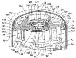
도 1은 본 발명의 일 실시예에 따른 스크롤 압축기 어셈블리의 단면도이다.
도 2는 도 1의 스크롤 압축기 실시예의 상부의 부분 단면 및 절단면도이다.
도 3은 도 2와 유사하지만 확대되고 다른 구조적 특징을 보여주기 위하여 다른 각도 및 단면을 고려한 도면이다.
도 4는 도 1의 실시예의 하부의 부분 단면 및 절단면도이다.
도 5는 본 발명의 실시예에 따른 스크롤 압축기 몸체와 올드함 키 커플링의 부분 단면 절개도이다.
도 6은 앞선 실시예에서 사용되는 이동 스크롤 부재 및 올드함 키 커플링의 전개도이다.
도 7은 구동 간격(여기서 구동 간격은 입증의 목적으로 크게 과장되어 있다)를 보여주는 이동 스크롤 부재와 본 발명의 실시예에서 보이는 올드함 키 접촉의 평면도이다.
도 8 및 도 9는 의도하지 않은 스크롤의 회전 및 키 표면의 모서리하중이 도 7의 비 대칭 키 접촉 표면이 없다면 일어날 수 있다는 것을 설명하는 대칭의 올드함 키 배열을 보여주는 점을 제외하고는 도 7과 유사한 도면이다.
도 10은 올드함 커플링의 두개의 키를 수용하는 보다 통상적인 두개의 슬롯 배열을 사용하는 이동 스크롤 부재의 평면도이다.
본 발명은 임의의 바람직한 실시예에 대하여 설명될 것이지만, 이러한 실시예들이 본 발명의 권리범위를 한정하는 것은 아니다. 반대로, 다른 모든 대체물, 수정, 등가물이 본 발명의 특허청구범위에 의해 정해지는 본 발명의 범위 내에 포함될 것이다. The accompanying drawings, which are incorporated in and constitute a part of the specification, illustrate various aspects of the invention and, together with the description, serve to explain the principles of the invention.
1 is a cross-sectional view of a scroll compressor assembly in accordance with an embodiment of the present invention.
2 is a partial cross-sectional and sectional view of an upper portion of the scroll compressor embodiment of FIG. 1;
Fig. 3 is similar to Fig. 2, but with different angles and cross sections taken into account in order to enlarge and show different structural features.
4 is a partial cross-sectional view and a cross-sectional view of the lower portion of the embodiment of FIG.
5 is a partial cross-sectional cutaway view of a scroll compressor body and old key key coupling in accordance with an embodiment of the present invention.
6 is an exploded view of the moving scroll member and oldham key coupling used in the previous embodiment.
7 is a plan view of the old scroll key contact as seen in an embodiment of the present invention with a moving scroll member showing the drive spacing (where the drive spacing is greatly exaggerated for demonstration purposes).
8 and 9 illustrate an symmetrical Oldham key arrangement illustrating that unintended scroll rotation and edge loading of the key surface may occur without the asymmetric key contact surface of FIG. Similar drawings.
10 is a plan view of a moving scroll member using a more conventional two slot arrangement to receive two keys of an old box coupling.
While the present invention will be described with respect to certain preferred embodiments, these embodiments are not intended to limit the scope of the present invention. On the contrary, it is intended to cover all alternatives, modifications, and equivalents falling within the scope of the invention as defined by the appended claims.
본 발명의 실시예에서, 구동 유닛(16)에 의해 구동될 수 있는 스크롤 압축기(14)를 내부에 갖는 외부 하우징(12)을 포함하는 스크롤 압축기 어셈블리(10)를 도시하고 있다. 스크롤 압축기 어셈블리는 냉동, 산업용 냉각, 냉각, 공기조화 또는 압축 유체가 필요한 다른 적절한 응용을 위한 냉동 회로에 배열될 수 있다. 적절한 연결 포트가 냉동 회로에의 연결을 위하여 제공되고 외부 하우징(12)를 통하여 확장되는 냉매 유입 포트(18)와 냉매 유출 포트(20)를 포함한다. 스크롤 압축기 어셈블리(10)는 스크롤 압축기(14)를 작동하기 위한 구동 유닛(16)의 작동을 통해 작동가능하고, 냉매 유입 포트(18)로 들어오고 압축된 고압 상태로 냉매 유출 포트(20)로 나가는 적절한 냉매 또는 다른 유체를 압축하게 된다.
In an embodiment of the present invention, there is shown a
외부 하우징(12)은 다양한 형태를 가질 수 있다. 바람직한 실시예에서는, 상기 외부 하우징은 다수의 셀(shell) 부분을 포함하고 바람직하게는 중앙 원통형 하우징 섹션(24), 상부 끝 하우징 섹션(26) 및 하부 끝 하우징 섹션(28)을 포함하는 3개의 셀 섹션이 된다. 바람직하게는, 하우징 섹션(24,26,28)은 적절한 강판으로 형성되고 외부 하우징(12)를 영구적으로 밀봉하기 위해 서로 용접된다. 그러나, 하우징의 해체가 요구되는 경우, 금속 캐스팅 또는 기계가공된 요소를 포함할 수 있도록 다른 외부 하우징 설비가 제공될 수 있다.
The
중앙 하우징 섹션(24)은 바람직하게는 원통형이고 상부와 하부 끝 하우징 섹션(26,28)과 포개어 끼워진다. 이는 스크롤 압축기(14)와 구동 유닛(16)을 보호하도록 밀봉된 챔버(30)을 형성하게 된다. 각각의 상부 및 하부 끝 하우징 섹션(26,28)은 중앙 섹션(24)과 짝이 되고 외부 하우징(12)의 상부 및 하부 끝을 폐쇄하도록 일반적으로 돔 형상이고 각각 실린더형의 측면 벽 영역(32,34)을 포함한다. 도 1에서와 같이, 상부 측면 벽 영역(32)은 텔레스코픽하게 중앙 하우징 섹션(24)과 겹쳐져 있고 외부적으로 환상형의 용접 영역을 따라 중앙 하우징 섹션(24)의 상부 끝까지 용접된다. 이와 유사하게 하부 끝 하우징 섹션(28)의 하부 측면 벽 영역(34)은 텔레스코픽하게 상기 중앙 하우징 섹션(24)과 겹쳐져 있고(그러나 중앙 하우징 섹션(24)의 외부보다는 내부측으로 장착된다), 환상의 용접 영역으로 외부적으로 용접된다.
The
구동 유닛(16)은 바람직하게는 전기 모터 어셈블리(40)가 되며, 상부 및 하부 베어링 부재(42,44)에 의해 지지된다. 상기 모터 어셈블리(40)는 축(46)을 회전시키고 구동한다. 상기 전기 모터 어셈블리(40)는 일반적으로 외부 중공형 모터 하우징(48), 전기 코일을 포함하는 스테이터(50) 및 구동 축(46)과 함께 회전하기 위해 결합되어 있는 로터(52)를 포함한다. 스테이터(50)에 전원을 인가하면 회전가능하게 로터(52)를 구동하고 그에 의해 구동 축(46)이 중앙 축(54)을 중심으로 회전한다.
The
도 1 및 도 4를 참고하면, 하부 베어링 부재(44)는 구동축(46)이 회전 지지를 위하여 연결되는 원통형의 베어링(60)을 제공하기 위한 중심 부싱 및 개구부를 포함하는 중심 원통형 허브(58)를 포함한다. 복수개의 암(62) 및 통상적으로 적어도 3개의 암이 바람직하게는 등 각도 간격으로 배열된 채로 베어링 중심 허브(58)로부터 외측으로 방사상으로 돌출된다. 이러한 지지암(62)들은 하부 외부 하우징 섹션(28)의 하부 측벽 영역(34)의 종단 원형 모서리에 의해 제공되는 원형 장착 표면(64)에 맞물리고 장착된다. 이와 같이 상기 하부 하우징 섹션(28)은 하부 베어링 부재(44)를 배열하고, 지지할 뿐 아니라 장착하도록 할 수 있고, 이에 의해 스크롤 압축기 어셈블리의 내부 구성요소들이 지지될 수 있도록 베이스의 역할을 하게 된다.
1 and 4, the
하부 베어링 부재(44)는 순차적으로 중심 허브(58)의 꼭대기를 따라 외측으로 돌출되는 하부 베어링 부재(44)의 평판형 턱(ledge) 영역(68)에 형성되는 원형 시트(66)에 의해 원통형 모터 하우징(48)을 지지한다. 지지암(62)은 또한 바람직하게는 중앙 하우징 섹션의 내부 직경과 거의 근접하게 공차를 갖는다. 상기 지지암(62)은 하부 베어링 부재(44)를 중심에 맞추어 배열하기 위하여 중앙 하우징 섹션(24)의 내경 표면과 맞물리게 될 수 있고, 이에 의해 중심축(54)의 위치를 유지한다. 이는 하부 베어링 부재(44) 및 외부 하우징(12) 사이의 억지 끼워맞춤 지지 배열에 의해 가능하게 된다.(도 4 참조) 도 1에 도시한 바와 같이, 보다 바람직한 다른 구성에 따르면, 하부 베어링은 중심 하우징 섹션(24)에 차례로 부착되는 하부 하우징 섹션(28)과 맞물린다. 이와 같이, 외부 모터 하우징(48)은 하부 베어링 부재(44)의 단차가 형성된 시트(66)을 따라 억지 끼워맞춤되는 방식으로 지지될 수 있다. 도시한 바와 같이, 나사가 모터 하우징을 하부 베어링 부재(44)에 단단히 체결하는데 사용될 수 있다.
The
구동축(46)은 중심축(54)과 동심원적인 배열을 이루고 있는 복수개의 점진적으로 작아지는 직경을 갖는 섹션(46a-46d)으로 형성된다. 가장 작은 직경 섹션(46d)은 하부 베어링 부재(44) 내에 다음으로 작은 섹션(46c)과 함께 하부 베어링 부재(44) 상에 구동축(46)의 축방향 지지를 위한 단차(72)를 형성하도록 회전을 위해 지지된다. 가장 큰 섹션(46a)은 상부 베어링 부재(42) 내에 회전을 위해 지지된다.
The
구동축(46)은 중심축(54)에 대하여 오프셋(offset)이 형성되는 오프셋 축에 대하여 원통형 구동 표면(75)을 갖도록 편심 오프셋 구동 섹션(74)을 추가적으로 포함하게 된다. 이러한 오프셋 구동 섹션(74)은 구동축(46)이 중심축(54)을 따라 회전할 때 스크롤 압축기의 이동 부재가 선회궤도를 형성하면서 구동하도록 스크롤 압축기(14)의 이동 스크롤 부재의 캐비티(cavity) 내에 지지된다. 이와 같은 모든 베어링 표면의 윤활을 제공하기 위하여, 외부 하우징(12)은 하부 끝단에 적절한 오일 윤활이 제공되도록 오일 윤활 섬프(sump, 웅덩이)(76)를 제공한다. 구동축(46)은 오일 윤활 파이프 및 구동축이 회전할 때 오일 펌프로써 작동하는 임펠러(78)를 갖고, 이에 의해 윤활 섬프(76)로부터 구동축(46) 내에 형성되는 내부 윤활 통로(80) 내로 오일을 퍼올리게 된다. 구동축(46)의 회전동안, 원심력이 중력에 대항하여 윤활 통로(80)를 통해 윤활 오일을 상승시키게 된다. 윤활 통로(80)는 도시한 바와 같이 적절한 베어링 표면에 오일을 원심력을 통해 공급하기 위해 다양한 방사상의 통로를 포함하게 되고, 이에 의해 원하는 바와 같이 슬라이딩 표면을 윤활하게 된다.
The
상부 베어링 부재(42)는 그 안에 구동축(46)의 가장 큰 섹션(46a)이 회전을 위해 지지되는 중심 베어링 허브(84)를 포함한다. 외부 말단 지지 림(88)에 합쳐지는 지지 웨브(web)(86)가 베어링 허브(84)로부터 외측으로 연장 형성된다. 지지 웨브(86)를 따라 중공형의 단차형성되는 장착 표면(90)이 제공되는데, 이는 원통형의 모터 하우징(48)의 상부 끝단과 함께 억지 끼워맞춤되며, 이에 의해 축방향 및 반경방향 위치를 제공하게 된다. 모터 하우징(48)은 또한 상부 베어링 부재(42)에 나사를 통해 체결될 수 있다. 외부 말단 지지 림(88)은 또한 외부 하우징(12)과 억지 끼워맞춤될 수 있는 외부 중공형의 단차형성되는 장착 표면(92)을 포함할 수 있다. 예를 들면, 외부 말단 림(88)은 축방향으로 장착 표면(92)과 맞물릴 수 있는데, 이는 직경을 통해서가 아닌 축(54)에 수직인 가로 평면 상에서 맞물리게 되는 것이다. 중심맞춤을 위하여, 중심 하우징 섹션(24)과 지지 림(88) 사이의 표면(92) 바로 밑에 직경방향의 끼워맞춤이 제공된다. 특히, 텔레스코픽 중심부와 상부 끝 하우징 섹션(24,26) 사이에 내부 원형 단차(94)가 정의되는데, 이는 상부 베어링 부재(42)의 외부 중공형 단차(92)에 대하여 축방향으로 또한 반경방향으로 배열된다.
The
또한 상부 베어링 부재(42)가 축방향 트러스트(thrust) 표면(96)에 의한 베어링 지지를 통해 이동 스크롤 부재에 축방향 트러스트 지지를 제공한다. 이는 단일 유닛 요소에 의해 일체로 제공될 수 있는 반면에, 단차진 중공형 계면(100)을 따라 상부 베어링 부재(42)의 상부 부분에 끼워맞춰지는 분리된 칼라(collar) 부재(98)에 의해 제공되는 것으로 도시되고 있다. 칼라 부재(98)는, 편심 오프셋 구동 섹션(74)을 수용하기 위해 제공되고, 이동 스크롤 압축기 부재(112)의 수용부 내에 제공되는 선회궤도 편심 운동을 허용하는데 있어서, 충분한 크기의 중심 개구부(102)를 형성하게 된다.
The
스크롤 압축기(14)의 상세한 사항으로 돌아가면, 바람직하게는 고정되는 고정 스크롤 압축기 몸체(110) 및 이동 스크롤 압축기 몸체(112)를 포함하는 제1 및 제2 스크롤 압축기 몸체에 의해 스크롤 압축기 몸체가 제공된다. 상기 이동 스크롤 압축기 몸체(112)는 냉매를 압축하기 위한 목적으로 고정 스크롤 압축기 몸체(110)에 대하여 선회궤도 운동하도록 배열된다. 상기 고정 스크롤 압축기 몸체는 평판형 베이스(116)로부터 축방향으로 돌출되는 제1 리브(114)를 포함하고 나선형상으로 설계된다. 이와 유사하게, 제2 이동 스크롤 압축기 몸체(112)는 평판형 베이스(120)로부터 축방향으로 돌출되는 제2 스크롤 리브(118)를 포함하고 유사한 나선형으로 설계된다. 상기 스크롤 리브(114,118)는 각각의 다른 압축기 몸체(112,110)의 각각의 베이스 표면(120,116)에 밀봉되도록 서로 맞물린다. 이러한 결과로, 복수의 압축 챔버(122)가 스크롤 리브(114,118)와 압축기 몸체(112,110)의 베이스(120,116) 사이에 형성된다. 챔버(122) 내에서, 냉매의 점진적인 압축이 수행된다. 냉매는 외부 방사상 영역(도 2-3 참조) 내에 스크롤 리브(114,118)를 둘러싸는 유입 영역(124)을 거쳐 초기 낮은 압력으로 흐른다. 챔버(122) 내의 점진적인 압축을 따라(챔버는 방사상 내부로 점진적으로 한정됨에 따라), 냉매는 고정 스크롤 압축기 몸체(110)의 베이스(116) 내에서 중심부에 형성되는 압축 유출부(126)를 거쳐 유출된다. 고압으로 압축되는 냉매는 스크롤 압축기가 작동하는 동안 압축 유출부(126)를 거쳐 챔버(122)를 나갈 수 있게 된다.
Returning to the details of the
이동 스크롤 압축기 몸체(112)는 구동축(46)의 편심 오프셋 구동 섹션(74)과 맞물린다. 보다 상세하게는, 이동 스크롤 압축기 몸체(112)의 수용부는 미끄러질 수 있는 베어링 표면을 갖는 편심 오프셋 구동 섹션(74)을 슬라이딩 가능하도록 수용하는 원통형 부싱 구동 허브(128)를 포함한다. 상세하게, 편심 오프셋 구동 섹션(74)은 구동축(46)의 중심축(54)에 대한 회전동안 중심축(54)에 대한 선회궤도로 상기 이동 스크롤 압축기 몸체(112)를 움직이기 위하여 원통형 구동 허브(128)와 맞물리게 된다. 이와 같은 오프셋 관계가 중심축(54)에 대하여 무게 불균형을 초래하는 점을 고려하여, 상기 어셈블리는 바람직하게는 구동축(46)에 고정 각도방향으로 고정되어 장착되는 카운터 웨이트(130)를 포함하게 된다. 상기 카운터 웨이트(130)는 선회궤도 경로로 구동되는 이동 스크롤 압축기 몸체(112) 및 편심 오프셋 구동 섹션(74)에 의해 발생하는 무게 불균형의 오프셋으로 작동하게 된다. 상기 카운터 웨이트(130)는 부착 칼라(attachment collar, 132) 및 오프셋 웨이트 영역(134)을 포함하게 되고, 이는 카운터 웨이트 효과를 제공하게 되고 하부 카운터 웨이트(135)와 함께 중심축(54)에 대하여 회전하는 전체 무게의 균형을 이루게 된다. 이는 내부적으로 균형을 주는 것 또는 외부 관성력을 제거하는 것에 의해 전체 어셈블리의 진동 및 노이즈를 감소시키게 된다.
The movable
도 1-3을 참고하면, 특히 도 2에서, 스크롤 압축기의 가이드 움직임을 볼 수 있다. 고정 스크롤 압축기 몸체(110)에 대하여 이동 스크롤 압축기 몸체(112)의 선회 궤도 운동을 가이드하기 위하여, 적절한 키 커플링(140)이 제공될 수 있다. 키 커플링은 종종 스크롤 압축기 분야에서 "올드함 커플링(Oldham Coupling)"으로 불린다. 본 실시예에서, 상기 키 커플링(140)은 외부 링 몸체(142)를 포함하고, 제1 가로축(146)을 따라 선형으로 배열되고, 제1 가로축(146)을 따라 선형으로 배열되고 정렬되는 두 개의 각각의 키웨이 트랙(148) 내에서 인접하게 또한 선형으로 슬라이딩 되는, 두개의 제1 키(144)를 포함한다. 제1 가로축(146)을 따른 키 커플링(140)의 직선 움직임이 외부 하우징(12)에 대하여 선형이고 중심축(54)에 대하여 수직이 되도록 하기 위하여, 상기 키웨이 트랙(148)은 고정적인 고정 스크롤 압축기 몸체(110)에 의해 형성된다. 상기 키는 슬롯, 그로브(groove), 또는 도시한 바와 같이, 키 커플링(140)의 링 몸체(142)에서 돌출되는 돌출부를 포함할 수 있다. 제1 가로축(146) 상에서의 움직임의 이와 같은 제어는 이동 스크롤 압축기 몸체(112)의 전체 중의 일부의 선회궤도를 가이드하게 된다.
Referring to Figs. 1-3, in particular in Fig. 2, the guide movement of the scroll compressor can be seen. A suitable
추가적으로, 상기 키 커플링은 제2 키(152)의 대향하는 페어(pair, 쌍)들이 제1 가로축(146)에 수직인 제2 횡단 가로축(154)에 대하여 실질적으로 평행하게 배열되는 4개의 제2 키(152)를 포함한다. 두 세트의 제2 키(152)가 이동 스크롤 압축기 몸체의 반대측면의 베이스(120)로부터 돌출되는 돌출 슬라이딩 가이드 부분(156)을 수용하도록 함께 작동한다. 상기 가이드 부분(156)은 제2 키(152)의 세트를 따라 가이드 부분(156)의 슬라이딩 선형 안내 움직임에 의해 제2 횡단 가로축을 따라 선형 움직임을 하도록 안내되고 선형으로 맞물리게 된다.
In addition, the key coupling may include four (4) pairs of opposing pairs of
키 커플링(140)에 의해, 이동 스크롤 압축기 몸체(112)는 제1 가로축(146) 및 제2 횡단 가로축(154)를 따라 고정 스크롤 압축기 몸체(110)에 대하여 구속되는 움직임을 갖는다. 이는 이동 스크롤 몸체가 병진운동만을 허용하도록 어떠한 상대적인 회전도 방지하게 된다. 보다 상세하게는, 상기 고정 스크롤 압축기 몸체(110)는 키 커플링(140)이 제1 가로축(146)을 따라 선형 움직임을 하도록 움직임을 제한하게 되고; 차례로, 상기 키 커플링(140)이 제1 가로축(146)을 따라 이동할 때 제1 가로축(146)을 따라 이동 스크롤(112)을 같이 수반하게 된다. 부가적으로, 이동 스크롤 압축기 몸체는 제1 키(152)들 사이에서 수용되고 슬라이딩되는 가이드 부분(156)에 의해 제공되는 상대적인 슬라이딩 움직임에 의해 제2 횡단 가로축(154)을 따라 키 커플링(140)에 대하여 독립적으로 움직일 수 있게 된다. 두 개의 수직인 축(146,154)에서의 동시에 움직이는 것이 허용되기 때문에, 이동 스크롤 압축기 몸체(112)의 원통형 구동 허브(128) 상의 구동축(46)의 편심 오프셋 구동 섹션(74)에 의해 허용되는 편심 움직임이 고정 스크롤 압축기 몸체(110)에 대한 이동 스크롤 압축기 몸체(112)의 선회 궤도 움직임으로 전사된다.
The movable
고정 스크롤 압축기 몸체(110)에 대하여 보다 상세하게 언급하면, 몸체(110)는 그들 사이에서 축방향으로 또한 수직으로 연장되는 연장부에 의해 상부 베어링 부재(42)에 고정되고, 또한 이동 스크롤 압축기 몸체(112)의 외부를 감싸도록 고정된다. 도시된 실시예에서, 고정 스크롤 압축기 몸체(110)는 베이스(116)로부터 스크롤 리브와 같이 같은 측면에서 돌출되는 복수개의 축방향 돌출 레그(158, 도 2)를 포함한다. 이러한 레그(158)들은 상부 베어링 부재(42)의 상부 측과 맞물리게 되고 장착된다. 바람직하게는, 볼트(160, 도 2)가 고정 스크롤 압축기 몸체(110)를 상부 베어링 부재(42)에 고정하도록 체결하는데 제공된다. 볼트(160)는 고정 스크롤 압축기 몸체의 레그(158)를 통해 축방향으로 연장되고 상부 베어링 부재(42)의 대응하는 나사 개구부에 나사결합되고 체결된다. 고정 스크롤 압축기 몸체(110)의 추가적인 지지 및 고정을 위하여, 고정 스크롤 압축기 몸체의 외주부는 외부 하우징(10), 보다 상세하게는 상부 끝 하우징 섹션(26)의 원통형 내부 표면에 인접하게 수용되는 원통형 표면(162)을 포함한다. 상기 표면(162)과 측면벽(32) 사이의 공차 간격은 상부 하우징(26) 어셈블리가 압축기 어셈블리 위에 오도록 허용하게 되고 그 후에 O링 씰(O-ring seal)(164)을 포함하도록 한다. O링 씰(164)은 압축된 고압 유체가 외부 하우징(12) 내부의 압축되지 않은 섹션/섬프 영역으로 누설되는 것을 방지하도록 원통형 배열 표면(162)과 외부 하우징(12) 사이의 영역을 밀봉하게 된다. 상기 씰(164)은 반경방향으로 외측방향으로 형성되는 중공형의 그루브(166)에 장착될 수 있다.
In more detail with respect to the fixed
도 1-3, 특히 도 3을 참고하면, 고정 스크롤(110)의 상부 측면(예를 들어, 스크롤 리브의 반대측면)은 부유성 배플(baffle) 부재(170)를 지지한다. 고정 스크롤 압축기 몸체(110)의 상부 측면은 중공형의, 보다 상세하게는 원통형의 내부 허브 영역(172)과 베이스(116)의 방사상으로 뻗어있는 디스크 영역(176)에 의해 연결되는 외측으로 배열된 주변부 림(174)을 포함한다. 허브(172)와 림(174) 사이에는 배플 부재(170)가 수용되는 중공형의 피스톤형 챔버(178)가 제공된다. 이러한 배열과 함께, 배플 부재(170) 및 고정 스크롤 압축기 몸체(110)의 조합은 하우징(10) 내에서 고압 챔버(180)와 저압 영역을 분리하는 역할을 한다. 배플 부재(170)가 고정 스크롤 압축기 몸체(110)의 외부 주변부 림(174) 내에서 맞물리고 방사상으로 장착되는 것으로 도시되어 있지만, 상기 배플 부재(170)는 선택적으로 외부 하우징(12)의 내부 표면에 원통형으로 직접 배열될 수도 있다.
1-3, and particularly FIG. 3, the upper side of the fixed scroll 110 (e.g., the opposite side of the scroll rib) supports the floating
실시예에 도시된 바와 같이, 또한 특히 도 3을 참고하면, 상기 배플 부재(170)는 내부 허브 영역(184), 디스크 영역(186) 및 외부 주변부 림 영역(188)을 포함한다. 강성을 제공하기 위하여, 허브 영역(184)과 주변부 림 영역(188) 사이의 디스크 영역(186)의 상부 측면을 따라 뻗어있는 복수개의 방사상의 확장 리브(190)가 일체로 제공될 수 있고 또한 바람직하게는 등 각도간격으로 중심축(54)에 대하여 배열될 수 있다. 외부 하우징(12)의 나머지부분으로부터 고압 챔버(180)를 분리하는 부가적 기능에 더하여 배플 부재(170)는 또한 고압 챔버(180)에 의해 발생하는 압력 하중을 고정 스크롤 압축기 몸체(110)의 내부 영역으로부터 고정 스크롤 압축기 몸체(110)의 외부 주변부 영역을 향해 전달하는 기능을 갖는다. 외부 주변부 영역에서, 압력 하중은 외부 하우징(12)에 의해서 전달될 수 있고 또한 보다 직접적으로 이동될 수 있고, 그에 의해 구성요소들에 압력이 가해지는 것을 피하거나 적어도 최소화할 수 있으며, 실질적으로 스크롤 몸체와 같은 작동 구성요소의 변형 또는 편차를 피할 수 있다. 바람직하게는, 상기 배플 부재(170)는 내부 주변부 영역을 따라 고정 스크롤 압축기 몸체(110)에 대하여 부유가능하게 된다. 이는 예를 들면, 각각의 허브 영역을 따라 고정 스크롤 압축기 몸체의 원통형 슬라이딩 표면과 배플 부재 사이의 슬라이딩 원통형 계면(192)에 의해 도시된 바와 같이 달성될 수 있다. 고압 챔버(180) 내의 압축된 고압 냉매가 배플 부재(170) 상에서 작동하기 때문에, 다른 경우라면 마찰 접촉에 의해 일어날 수 있는 하중이 실질적으로 내부 영역으로 전달되지 않을 수 있게 된다. 대신하여, 축 접촉 인터페이스 링(194)이 각각의 림 영역이 고정 스크롤 압축기 몸체(110) 및 배플 부재(170)에 배열되는 위치인 방사상의 외부 주변부에 제공된다. 바람직하게는, 중공형의 축 간격(196)이 배플 부재(170)의 내경과 고정 스크롤 압축기 몸체(110)의 상부면 사이에 제공된다. 상기 중공형의 축 간격(196)은 배플 부재의 방사상의 가장 내부 부분과 스크롤 부재와의 사이에 형성되고 고압 챔버(180) 내에 압축되는 고압 냉매에 의해 야기되는 압력 하중에 대응하여 크기를 감소하게 된다. 상기 간격(196)은 압력과 하중의 덜어짐에 따라 이완된 크기로 확장할 수 있게 된다.
3, the
하중 전달을 가장 효과적으로 가능하게 하기 위하여, 중공형의 중간 또는 낮은 압력 챔버(198)가 배플 부재(170)와 고정 스크롤 압축기 몸체(110) 사이에 형성된다. 이러한 중간 또는 낮은 압력 챔버는 도시한 바와 같은 낮은 섬프 압력이거나, 중간 압력이 될 수 있다.(예를 들면, 고정 스크롤 압축기 몸체를 통해 형성되어 각각의 압력 챔버(122)들 중 하나를 챔버(198)와 연결하기 위한 유체 이동 통로를 통해) 그러므로 하중 전달 특성은 최선의 응력/변형 관리를 위해 선택되는 낮은 또는 중간의 압력에 기초하여 구성될 수 있다. 어떤 경우에도, 작동 중에 중간 또는 낮은 압력 챔버(198) 내의 압력은 실질적으로 고압 챔버(180) 보다 낮고, 이에 의해 압력 차이와 배플 부재(170)를 경유하여 생기는 하중을 야기하게 된다.
A hollow intermediate or
누설을 방지하고 보다 나은 하중 전달을 가능하게 하기 위하여, 내부 및 외부 씰(204,206)이 제공될 수 있고, 이들 둘은 모두 탄력있고, 탄성적인 O링 씰 부재이다. 내부 씰(204)은 바람직하게는 방사상의 씰이고 배플 부재(170)의 내경을 따라 형성되는 내부 그루브(208)에 방사상으로 내접하도록 배열된다. 유사하게 외부 씰(206)은 주변부 림 영역(188) 내에 배플 부재(170)의 외경을 따라 형성되는 외부 그루브(210)에 방사상으로 외접하도록 배열된다. 방사상의 씰이 외부 영역에서 도시됨에도 불구하고, 이를 대신하여 또는 이에 더하여 축방향 씰이 축 접촉 인터페이스 링(194)를 따라 제공될 수 있다.
In order to prevent leakage and enable better load transfer, inner and
배플 부재(170)는 스탬핑된(stamped) 스틸 요소가 될 수 있는 반면에, 바람직하게는 또한 도시된 바와 같이, 배플 부재(170)는 앞서 논의된 바와 같은 다양한 구조적 특징을 갖도록 확장된 특성을 제공하기 위하여 주조 및/또는 기계가공된 부재가 될 수 있다.(또한 알루미늄이 될 수 있다.) 이러한 방식으로 배플 부재를 만드는 것에 의해, 이러한 배플의 중 스탬핑(heavy stamping)을 피할 수 있게 된다.
The
부가적으로, 상기 배플 부재(170)는 고정된 스크롤 압축기 몸체(110)에 장착될 수 있다. 상세하게는, 도시된 바와 같이, 배플 부재(170)의 내부 허브 영역(184)의 방사상으로 돌출되는 중공형 플랜지(214)는 멈춤 플레이트(212) 및 고정 스크롤 압축기 몸체(110) 사이에 축방향으로 갖히게 된다. 상기 멈춤 플레이트(212)는 고정 스크롤 압축기 몸체(210)에 볼트(216)로 장착된다. 상기 멈춤 플레이트(212)는 고정 스크롤 압축기 몸체(110)의 내부 허브(172)를 지나 방사상으로 돌출되는 외부 턱(218)을 포함한다. 멈츰 플레이트 턱(218)은 배플 부재(170)를 위한 멈춤 및 유지를 위한 기능을 하게 된다. 이러한 방식으로, 상기 멈춤 플레이트(212)는 배플 부재(170)가 그에 의해 이송되도록 고정 스크롤 압축기 몸체(110)에 배플 부재(170)를 유지하는 기능을 하게 된다.
Additionally, the
도시한 바와 같이, 멈춤 플레이트(212)는 체크 밸브(220)의 일부가 될 수 있다. 체크 밸브는 내부 허브(172) 내에 고정 스크롤 압축기 몸체의 유출 영역에 형성되는 챔버 내에 포함되는 이동 밸브 플레이트 요소(222)를 포함하게 된다. 따라서 멈춤 플레이트(212)는 이동 밸브 플레이트 요소(222)가 위치하는 체크 밸브 챔버(224)를 폐쇄하게 된다. 체크 밸브 챔버 내에는 중심축(54)을 따라 체크 밸브(220)의 움직임을 가이드하는 원통형 가이드 벽 표면(226)이 제공된다. 오목부(228)는 이동 밸브 플레이트 요소(222)가 밸브 시트(230)로부터 들어올려질 때 체크 밸브를 통해 압축된 냉매를 통과하는 것을 허용하기 위하여 가이드 벽(226)의 상부 영역 내에 제공된다. 개구부(232)가 스크롤 압축기로부터 고압 챔버(180)로의 압축 가스의 이동을 가능하게 하기 위하여 멈춤 플레이트(212) 내에 제공된다. 체크 밸브는 스크롤 압축기가 작동할 때 압축된 냉매가 밸브 플레이트 요소(222)가 그 밸브 시트(230)로부터 떨어지는 것에 의해 압축 유출구(126)를 통해 스크롤 압축기 몸체가 빠져나가는 것을 허용하기 위해, 일방향 유동을 허용하도록 작동한다. 그러나, 구동 유닛이 정지되거나 스크롤 압축기가 더 이상 작동하지 않게 되면, 고압 챔버(180) 내의 고압이 이동 밸브 플레이트 요소(222)를 밸브 시트(230) 상으로 돌아가게 만든다. 이는 체크 밸브(220)를 폐쇄시키고, 이에 의해 압축된 냉매의 스크롤 압축기를 경유하는 역류를 방지하게 된다.
As shown, the
운전 동안에, 스크롤 압축기 어셈블리(10)는 하우징 유입 포트(18)에서 낮은 압력의 냉매를 수용하도록 작동하고, 하우징 유출 포트(20)를 통한 유출물로 형성될 수 있는 고압 챔버(180)로 전달하기 위해 냉매를 압축하게 된다. 도 4에서 도시한 바와 같이, 내부 관로(234)가 낮은 압력의 냉매를 유입 포트(18)로부터 모터 하우징 유입구(238)를 거쳐 모터 하우징 내로 안내하도록 하우징(12)의 내부으로 연결될 수 있다. 이는 낮은 압력의 냉매가 모터를 경유하여 유동하도록 하게 되고 모터의 운전에 의해 발생하는 열을 모터로부터 제거할 수 있게 된다. 그리고 나서 낮은 압력 냉매는 모터 하우징을 통하여 또한 여유 공간을 통과하여 그 안에서 중심축(54)에 대해 등각도 간격으로 배열되는 복수개의 모터 하우징 유출구(240) (도 2)를 통해 유출될 수 있는 상부 끝단을 향해 길이방향으로 통과할 수 있게 된다. During operation, the
모터 하우징 유출구(240)는 모터 하우징(48), 상부 베어링 부재(42) 또는 모터 하우징과 상부 베어링 부재의 조합(도 2에 도시한 바와 같이 그들 사이에 형성되는 간격에 의해)에 의한 것 중 어느 하나에 의해 형성될 수 있다. 모터 하우징 유출구(240)의 출구에서, 낮은 압력의 냉매는 모터 하우징과 외부 하우징 사이에 형성되는 중공형 챔버(242)로 들어간다. 그곳에서부터, 낮은 압력의 냉매가 도 3에 도시된 바와 같은 베어링 부재(42)와 하우징(12) 사이의 간격(또는 대신해서 베어링 부재(42) 내의 홀)을 형성하기 위해 상부 베어링 부재(42)의 반대편 상의 오목부에 형성되는 한쌍의 다른 외부 주변부 관통 포트(244)를 통해 상부 베어링 부재를 통과할 수 있게 된다. 관통 포트(244)는 모터 하우징 유출구(240)에 대하여 각도를 이루며 배열될 수 있다. 상부 베어링 부재(42)를 통과하면서, 낮은 압력의 냉매는 결국 스크롤 압축기 몸체(110,112)의 유입 영역(124)으로 들어가게 된다. 유입 영역(124)으로부터, 상기 낮은 압력의 냉매는 결국 반대편의 스크롤 리브(14,118)에 들어가게 되고(고정 스크롤 압축기 몸체의 각 면마다 하나의 유입), 다음에 체크 밸브(220)를 통과하여 고압 챔버(180)로 들어가도록 하는 압축 유출구(126)에서 최대의 압축 상태에 도달하게 하는 챔버(122)를 통해 점진적으로 압축하게 된다. 그곳에서부터, 고압으로 압축된 냉매가 냉매 하우징 유출 포트(20)를 통하여 스크롤 압축기 어셈블리(10)로부터 통과할 수 있게 된다.
The
본 발명에 의하면, 도시한 실시예는 하나 또는 모든 스크롤 몸체와 키 커플링 사이의 접촉 배열에 대하여 보다 진보한 부분을 또한 포함하게 되며, 이는 이하에서 상세하게 설명된다.
According to the present invention, the illustrated embodiment will also include more advanced parts with respect to the contact arrangement between one or all scroll bodies and the key coupling, which is described in detail below.
도 5-7, 특히 도 7을 참고하면, 4개의 슬라이딩 접촉(250)이 키 커플링(140)과 이동 스크롤 압축기 몸체(112) 사이에 제공된다. 도시한 바와 같이, 각각의 슬라이딩 접촉(250)은 그 자체의 분리된 사분면(252) 내에 포함된다.(상기 사분면(252)은 서로 수직한 가로축(146, 154)에 의해 형성된다.) 각각의 슬라이딩 접촉(250)은 이동 스크롤 압축기 몸체와 키 커플링(140)의 키(152) 중의 하나에 의해 형성되는 다른 슬라이딩 면(256)에 의해 형성되는 슬라이딩 면(254)(예를 들면, 모서리와 같은 것)에 의해 제공된다. 도시한 바와 같이, 슬라이딩 접촉(250)의 조합된 쌍(258)이 제1 가로축(146)의 각각의 사이드에 제공된다.
5-7, in particular with reference to FIG. 7, four sliding
바람직하게는, 4개의 키(152)가 키 커플링(140)에 의해 제공되고 슬라이딩 면(256)을 제공하기 위해 링 몸체(142)로부터 돌출되며, 키(152)는 링 몸체(142)로부터 이동 스크롤 압축기 몸체(112)를 향해 축방향으로 돌출된다. 이를 대신하여, 모든 또는 몇몇의 키들이 반대로 이동 스크롤 압축기 몸체(112)의 베이스(120)로부터 돌출될 수 있다는 것이 또한 고려되고 여기서 개시되고 있다.
Preferably, four
도시한 바와 같이, 이동 스크롤 압축기 몸체 베이스(120)의 가이드 부분(156)이 이동 압축기 몸체 스크롤 리브(118)로부터 멀어지는 방향으로 제2 가로축(154)을 따라 서로 반대 방향으로 돌출되는 가로방향 확장 플랜지 부분(262)에 의해 제공된다. 스크롤 리브(118)로부터 멀어지도록 돌출되는 것에 의해, 상기 플랜지 부분(262)은 중심축(54)과 제2 가로축(154)에 의해 형성되는 평면과 평행한 평면에 놓여지는 슬라이딩 면(254)의 모서리를 제공할 수 있게 된다. 부가적으로, 플랜지 부분(262)이 제2 가로축(154) 상에 교차하여 대칭적으로 놓여지는 것을 볼 수 있다.
As shown, a transverse expansion flange in which the
바람직하게는, 도시한 바와 같이, 이동 스크롤 압축기 몸체(112)의 베이스(120)는 예를 들면 도 10에서 도시된 바와 같은 보다 일반적인 디자인과 비교할 때 본 디자인에서 제시되는 바와 같은 키 커플링에 의해 슬롯으로부터 자유롭고 또한 슬롯을 형성할 필요가 없게 된다. 이러한 시도의 하나의 잇점은 올드함 키 커플링과 상호작용하기 위하여 스크롤 베이스로부터 외측방향으로 돌출되는 귀 부분에 의한 공간을 확보할 필요가 없게 된다는 점이다. 본 디자인에서는, 귀 부분 구조가 없고 이러한 결과로 패키지의 전체 직경이 감소될 수 있다. 예를 들면, 적어도 30톤의 출력 용량을 갖는 스크롤 압축기를 위해, 하우징은 320mm 보다 작은 직경을 가질 수 있게 된다. 귀 부분 구조를 제거하는 것에 의해 이루어지는 사이즈의 감소가 귀 부분을 갖는 경우의 직경(264)과 귀 부분 없이 이루어지는 보다 작은 직경(266)을 도식화 한 도 10에 도시된다. 특히, 중심 셀은 35톤의 용량 또는 적절한 모터와 함께 그보다 잠재적으로 큰 용량(예를 들면 40톤의 용량이 가능하다)을 제공하면서도 직경이 310 mm 이하에서 가장 작게는 305mm 까지 줄어들 수 있다. 이러한 것은 또한 직경의 감소에 따른 셀의 무게의 감소가 대략적으로는 5-10kg을 포함하는 중요한 무게 감소가 이루어질 수 있다. 이는 스크롤 압축기 어셈블리(10)의 전체 무게를 줄이는데 중요한 이점을 제시할 수 있고 이에 의해 보다 쉬운 양산, 장착, 소재 절감을 포함하는 다양한 관점에서 보다 매력적으로 만들 수 있다. 반면에, 비교대상으로 32톤 스크롤 압축기 변위 용량을 갖는 것은 예를 들면 331 또는 333 mm 와 같은 330mm보다 큰 셀 사이즈를 갖게 된다.
Preferably, as shown, the
축방향 트러스트 하중을 전달하기 위해, 이동 스크롤 압축기 몸체(112)는 또한 가이딩 플랜지 부분(262)에 대하여 수직인 방향으로 돌출되는 플랜지 부분(268)을 포함하게 된다. 이러한 부가적인 플랜지 부분(268)은 바람직하게는 사이즈 절감 효과를 얻기 위해 가이드 플랜지 부분(262)에 의해 생성되는 직경 경계 내에 포함된다. 본 디자인의 추가적인 장점은 이동 스크롤 압축기 몸체(112)의 슬라이딩 면(254)이 개구되어 있고 슬롯을 포함하지 않는다는 것이다. 이는 원하는 공차 및 구동 간격을 생성하기 위한 피니싱 밀링과 같은 후속 기계 가공을 가능하게 하는 점에서 제조과정 중 장점을 제공할 수 있다.
To transmit the axial thrust load, the moving
바람직하게는, 본 출원에 대하여는 선택적으로는, 비 대칭 접촉 관계가 도 7에 도시된 바와 같이 또한 상기 키 커플러 및 적어도 하나의 스크롤 압축기 몸체 사이에 제공된다. 도 7의 비대칭적 배열과 도 8 및 9의 대칭적 배열을 비교하면, 대칭적 접촉 배열은 원하지 않는 회전 및 도 9에 도시한 바와 같은 키 표면의 모서리 하중을 초래할 수 있다. 이러한 도면들은 구동 간격이 제조 디자인 기준(공차를 고려하지 않고)에서 10 미크론 내지는 100 미크론 사이에 통상적으로 있다는 것을 고려할 때 구동 간격(270)들의 과장된 배열을 도시하고 있다. 이러한 구동 간격(270)들은 이동 스크롤 압축기 몸체(112)의 보다 쉬운 슬라이딩 움직임을 허용하고 쉬운 어셈블리를 허용하기 위해 제시된다. 예를 들면, 제조 공차는 표면이 보다 커지거나 또는 작아지도록 하는 것을 초래할 수 있다. 또한 몇몇 구동 간격은 끼워맞춤 관계 또는, 마찰력, 일시적으로 또는 항상 일어날 수 있는 온도변화에 의한 확장/수축, 및 다른 유사한 이유들에 의한 결합 관계와 반대로 슬라이딩 움직임을 원활하게 하기 위해 제공될 수 있다. 바람직하게는 도 7에 도시된 것과 같이, 구동 간격(270)은 슬라이딩 접촉(250)의 각각의 접촉쌍(258)들에서 서로 동일하지 않다. 특히, 모든 또는 거의 대부분의 구동 공차가 다른 슬라이딩 접촉(250b)에 제공되는 반면에 운전동안 계속적으로 관여하게 되는 슬라이딩 접촉(250a)은 대략 제로(zero)의 구동 간격으로 세팅된다. 슬라이딩 접촉(250b)은 예를 들면 스크롤 압축기가 정지하였을 때 및 반대방향으로의 상대적인 회전을 방지하기 위하여, 또한 그에 의해 제2 가로축(154)을 따라 스크롤 압축기가 선형 변형되는 것을 제한하기 위해 관여할 수 있다.
Preferably, optionally for the present application, a non-symmetrical contact relationship is also provided between the key coupler and the at least one scroll compressor body as shown in FIG. 7. Comparing the asymmetrical arrangement of FIG. 7 with the symmetrical arrangement of FIGS. 8 and 9, the symmetrical contact arrangement can result in unwanted rotation and edge loading of the key surface as shown in FIG. 9. These figures show an exaggerated arrangement of
키의 슬라이딩 면(256)을 약간 오프셋을 갖게 하고 제2 가로축에 대하여 대칭적이지 않게 하는 것, 및/또는 이동 스크롤 압축기 몸체(112)의 슬라이딩 면(254)이 약간 오프셋을 갖고 또한/또는 제2 가로축(154)에 대하여 대칭적이지 않게 하는 것, 또는 이들의 조합을 포함하는 비 대칭의 구동 간격 배열을 위한 많은 방법이 존재한다. 도 7에 도시한 바와 같이, 페어 중 하나의 키가 그 페어의 다른 키와 비교할 때 제2 가로축(154)으로부터 약간 멀게 배열되도록 각각의 독립적인 키(152)의 페어(258)가 비 대칭적인 배열을 하게 된다. 이러한 인접한 키의 오프셋 배열은 스크롤 회전을 최소화하게 되고 하중이 냉매의 압축 동안 접촉(250a)에 부과되는 정상 운전 동안 스크롤 압축기 몸체 슬라이딩 면(254)과 키 커플링 슬라이딩 면(256)의 평행한 표면 하중을 제공한다. 다시말하자면, 정상 운전 동안 다른 접촉(250b)에 하중이 가해지지 않음을 고려할 때, 슬라이딩 접촉(250b)을 따라 구동 간격을 주로 또는 전체적으로 제공하면, 운전 정지시 스크롤 압축기 몸체의 약간 큰 반대방향 회전을 허용하게 되더라도 이는 보다 덜 중요한 요소가 되는데, 즉 스크롤 압축기가 작동하고 연속적인 베이스에 고 하중이 작용하는 동안에 스크롤의 원하지 않는 회전 및 키 표면의 모서리 하중이 보다 더 중요하게 된다. Making the sliding
이러한 대비는 도 7과 도 9를 통해 볼 수 있고, 여기서 스크롤 압축기 몸체는 도 7에 도시된 바와 같은 제2 가로축에 대하여 구동하게 되는 반면에, 도 9의 이동 스크롤 압축기 몸체(112)가 제2 가로축을 따라 직선적으로 전사될 때 스크롤의 원하지 않는 회전 및 키 표면의 모서리 하중이 도 9에서 도시한 경우에는 일어날 수 있다.
This contrast can be seen through FIGS. 7 and 9, where the scroll compressor body is driven about a second horizontal axis as shown in FIG. 7, while the moving
상술한 실시예 및 그와 관계된 다른사항들(예를 들면 구동 간격의 오프셋 배열이 제공될 수 있다)이 여기서 구동 간격의 제공에 의해 간격 반발을 정정하기 위한 수단을 제공하게 된다.
The above-described embodiment and other related matters (for example, an offset arrangement of driving intervals can be provided) provide a means for correcting the gap repulsion by providing the driving interval here.
유사한 공급이 또한 보다 통상적인 키 커플링을 위한 도 10에 도시된 바와 같이 실시예도에 제공될 수 있다. 상세하게는, 원하지 않는 회전 및 운전 동안의 원하지 않는 모서리 하중을 방지하기 위해 슬롯 내의 키의 슬라이딩 면을 보다 평행하게 유지하기 위해서, 이와 같은 비 대칭 관계가 슬롯 벽 중의 하나를 따라 구동 간격을 주는 것을 통해 유사하게 사용될 수 있다.
Similar supply may also be provided in the embodiment diagrams as shown in FIG. 10 for more conventional key couplings. Specifically, this non-symmetric relationship allows the driving distance along one of the slot walls to be more parallel to keep the sliding face of the key in the slot to prevent unwanted corner loads during rotation and operation. Can be similarly used.
본 발명에서 인용된 공개문헌, 특허출원 및 특허를 비롯한 모든 참조자료는 그 전체 내용이 개별적이고 구체적으로 참조로서 포함되는 것과 마찬가지로 본 발명에서 참조로서 포함된다.
All references, including published documents, patent applications, and patents, cited in the present invention, are incorporated by reference into the present disclosure as if they were each individually and specifically incorporated by reference.
본 발명을 기술하는 문맥(구체적으로는 첨부된 특허청구범위)에 사용된 "하나" 및 "전술한(상기)" 등의 용어는 본원에 달리 기재하거나 문맥상 명백히 모순되지 않는다면 단수 및 복수 형태를 모두 포함하는 것으로 해석해야 한다. "구비", "가짐", "포함" 및 "함유"라는 용어는 달리 언급하지 않는 한 "제한 없는 용어(open ended term)", 즉 (해당 내용을) 포함하지만 그에 한정되지 않는 용어로 해석해야 한다. 본원에서 여러 값들의 범위들을 기재하는 것은 그 범위에 속하는 각각의 값을 개별적으로 참조하는 축약방법일 뿐이며, 각각의 값은 본원에 개별적으로 개재되는 것과 마찬가지로 본원에 포함된다. 본원에 기재한 모든 방법들은 본원에 달리 기재하거나 문맥상 명백히 모순되지 않는다면 임의의 적절한 순서로 수행될 수 있다. 본원에 제공된 임의 또는 모든 예 또는 바람직한 용어(예를 들면 "등" 또는 "~와 같은")의 사용은 본 발명을 더 잘 설명하기 위한 것일 뿐이며 달리 특허청구범위에 정의되지 않는 한 본 발명의 범위를 한정하는 것은 아니다. 명세서의 어떠한 용어라도, 특허청구범위에 정의되지 않은 것을 본 발명의 실시에 필수적인 요소로 나타내는 것은 없다.
As used in the context of describing the invention (specifically, the appended claims), terms such as " one "and" Should be interpreted to include both. The terms "comprising", "having", "including" and "containing" are to be interpreted as including, but not limited to, an "open ended term" do. Describing a range of values herein is merely a shorthand method of individually referencing each value within that range, and each value is included herein as if it were individually recited herein. All methods described herein may be performed in any suitable order unless otherwise indicated herein or otherwise clearly contradicted by context. Use of any or all of the examples or preferred terms provided herein (e.g., "such" or "such as") is intended to better illustrate the present invention and, unless otherwise defined, But is not limited to. Nothing in the specification shall be construed as an essential element of the practice of the invention unless it is defined in the claims.
본 발명의 실시를 위해 발명자가 인지하는 최선 모드를 포함하는 본 발명의 바람직한 실시예에 대해 설명하였다. 해당 분야의 통상의 지식을 가진 자(당업자)는 전술한 상세한 설명으로부터 바람직한 실시예를 변형할 수 있을 것이다. 발명자는 당업자가 그와 같은 변형물을 적절하게 채용할 것을 예상하며, 본 발명은 본원에 특정된 것과 달리 실행되도록 의도되었다. 따라서, 본 발명은 적용 가능한 법이 허용하는 한 첨부한 특허청구범위에 정의된 주제의 모든 수정물과 등가물을 포함한다. 또한, 전술한 요소들의 모든 조합의 가능한 모든 변형물은 본원에 달리 기재하거나 문맥상 명백히 모순되지 않는 한 본 발명에 포함된다.
Preferred embodiments of the invention have been described, including the best mode known to the inventors for carrying out the invention. Those skilled in the art will be able to modify preferred embodiments from the foregoing detailed description. The inventors expect skilled artisans to employ such variations as appropriate, and the invention is intended to be practiced otherwise than as specified herein. Accordingly, the invention includes all modifications and equivalents of the subject matter defined in the appended claims as far as applicable law permits. In addition, all possible variations of all combinations of the foregoing elements are included in the present invention unless otherwise described herein or otherwise clearly contradicted by context.
Claims (16)
상기 제2 스크롤 몸체 상에서 작동하는 키 커플러; 및
서로 대향하는 관계로 배열되는 제1 및 제2 슬라이딩 접촉을 포함하고, 제2 슬라이딩 접촉과 비교하여 작은 구동 간격이 제1 슬라이딩 접촉을 따라 제공되고, 상기 키 커플러와 상기 제2 스크롤 몸체 사이의 비대칭 슬라이딩 접촉 배열;을 포함하고,
상기 스크롤 압축기 몸체는 각각의 베이스 및 상기 각각의 베이스로부터 돌출되어 서로 맞물리는 각각의 스크롤 리브를 갖고, 상기 스크롤 리브는 중심축을 감싸고 있고, 상기 스크롤 압축기 몸체는 제1 및 제2 가로축을 따라 서로에 대하여 움직일 수 있고, 상기 제1 및 제2 가로축은 상기 중심축에 대하여 수직인 평면상에서 서로 수직이고,
상기 제2 스크롤 몸체는 상기 키 커플러에 대하여 제2 가로축을 따라서 움직일 수 있는 것을 특징으로 하는 스크롤 압축기.
A scroll compressor body comprising a first scroll body and a second scroll body;
A key coupler operative on the second scroll body; And
A first and second sliding contact arranged in an opposite relationship to each other, wherein a small drive distance is provided along the first sliding contact as compared to the second sliding contact, and is asymmetrical between the key coupler and the second scroll body A sliding contact arrangement;
The scroll compressor body has a respective base and respective scroll ribs protruding from the respective bases and engaged with each other, the scroll ribs enclosing a central axis, and the scroll compressor bodies are connected to each other along the first and second horizontal axes. Moveable relative to each other, the first and second horizontal axes being perpendicular to each other on a plane perpendicular to the central axis,
And the second scroll body is movable along a second horizontal axis with respect to the key coupler.
상기 제1 및 제2 슬라이딩 접촉의 상기 구동 간격은 10에서 200 미크론(micron) 사이인 것을 특징으로 하는 스크롤 압축기.
The method of claim 1,
And said drive spacing of said first and second sliding contacts is between 10 and 200 microns.
상기 제1 슬라이딩 접촉은 영인 구동 간격을 갖고, 모든 구동 간격은 제2 슬라이딩 접촉에 제공되는 것을 특징으로 하는 스크롤 압축기.
3. The method of claim 2,
And the first sliding contact has a drive interval that is zero and all drive intervals are provided in the second sliding contact.
상기 키 커플러는 상기 가로축의 대향측으로 두 쌍을 포함하는 4개의 키를 포함하고, 상기 제2 스크롤 몸체는 대향하는 플랜지 부분을 포함하고, 각각의 플랜지 부분은 제1 및 제2 슬라이딩 접촉을 형성하도록 어느 한쌍의 키들 사이에 미끄러질 수 있도록 수용되는 것을 특징으로 하는 스크롤 압축기.
The method of claim 1,
The key coupler includes four keys comprising two pairs on opposite sides of the transverse axis, the second scroll body comprising opposing flange portions, each flange portion forming first and second sliding contacts. A scroll compressor, characterized in that it is accommodated to slide between any one pair of keys.
각각의 플랜지 부분은 각각의 키에 접촉하는 제1 및 제2 슬라이딩 표면을 갖고, 상기 제1 및 제2 슬라이딩 표면은 서로 다른 거리로 상기 제1 가로축으로부터 이격배열되는 것을 특징으로 하는 스크롤 압축기.
5. The method of claim 4,
Wherein each flange portion has first and second sliding surfaces in contact with each key, the first and second sliding surfaces being spaced apart from the first transverse axis at different distances.
각각의 키 쌍들은 제2 가로축의 대향 측면에 제1 및 제2 키를 포함하고, 각각의 키는 어느 하나의 플랜지 부분과 맞물리는 슬라이딩 표면을 갖고, 상기 슬라이딩 표면에서 상기 제1 키는 제2 키와 비교할 때 제2 가로축으로부터 더 멀리 이격 배열되는 것을 특징으로 하는 스크롤 압축기.
5. The method of claim 4,
Each key pair includes first and second keys on opposite sides of a second transverse axis, each key having a sliding surface that engages any one flange portion, where the first key is a second key. And arranged farther away from the second transverse axis as compared to the key.
상기 키 커플러는 키 커플러의 제1 가로축을 따른 움직임을 위하여 제1 스크롤 몸체에 형성되는 제1 스크롤 몸체 키 슬롯과 맞물리는 제5 및 제6 키를 포함하는 것을 특징으로 하는 스크롤 압축기.
5. The method of claim 4,
And the key coupler includes fifth and sixth keys engaged with a first scroll body key slot formed in the first scroll body for movement along the first horizontal axis of the key coupler.
상기 제2 스크롤 몸체는 상기 베이스로부터 외측으로 돌출되는 귀 및 슬롯을 포함하지 않는 것을 특징으로 하는 스크롤 압축기.
The method of claim 1,
And the second scroll body does not include ears and slots protruding outward from the base.
상기 스크롤 압축기 몸체를 담는 하우징을 추가적으로 포함하고, 상기 제1 스크롤 몸체는 상기 하우징에 대하여 고정되고, 상기 제2 스크롤 몸체는 상기 제1 스크롤 몸체에 대하여 선회궤도 경로로 상기 하우징에 대해 움직일 수 있도록 하는 것을 특징으로 하는 스크롤 압축기.
The method of claim 1,
A housing containing the scroll compressor body, wherein the first scroll body is fixed relative to the housing, and the second scroll body is movable relative to the housing in a pivotal path relative to the first scroll body. Scroll compressor, characterized in that.
상기 제1 및 제2 슬라이딩 접촉은 상기 키 커플러 및 상기 제2 스크롤 몸체 사이에서 중심축에 대하여 반대되는 각각의 제1 및 제2 회전 방향으로의 상대적인 회전을 방지하도록 하는 것을 특징으로 하는 스크롤 압축기.
The method of claim 1,
And the first and second sliding contacts prevent relative rotation between the key coupler and the second scroll body in respective first and second rotational directions opposite to a central axis.
적어도 하나의 가로축을 따라 안내 움직임을 위하여 적어도 하나의 스크롤 몸체 상에서 작동하는 커플링 수단;
구동 간격에 따른 키 간격 반발을 정정하는 수단;을 포함하고,
상기 스크롤 리브는 중심축을 감싸고 있고, 상기 스크롤 몸체는 상기 중심축에 대하여 수직인 평면상에서 서로 수직인 가로축들을 따라 서로에 대하여 움직일 수 있고,
구동 간격이 상기 커플링 수단 및 적어도 하나의 스크롤 몸체 사이에 제공되는 것을 특징으로 하는 스크롤 압축기.
A scroll body having a respective base and respective scroll ribs protruding from the respective bases and engaging each other;
Coupling means operating on at least one scroll body for guiding movement along at least one transverse axis;
Means for correcting a key interval repulsion according to the drive interval;
The scroll ribs surround a central axis, the scroll body can move relative to each other along horizontal axes perpendicular to each other on a plane perpendicular to the central axis,
A scroll compressor, characterized in that a drive gap is provided between said coupling means and at least one scroll body.
상기 적어도 하나의 스크롤 몸체 및 상기 커플링 수단 사이의 구동 간격은 10에서 200 미크론(micron) 사이인 것을 특징으로 하는 스크롤 압축기.
12. The method of claim 11,
And a drive spacing between said at least one scroll body and said coupling means is between 10 and 200 microns.
상기 정정 수단은 제1 및 제2 슬라이딩 접촉을 포함하고, 상기 제1 슬라이딩 접촉은 영인 구동 간격을 갖고, 모든 구동 간격은 상기 제2 슬라이딩 접촉에 제공되는 것을 특징으로 하는 스크롤 압축기.
13. The method of claim 12,
And said correcting means comprises first and second sliding contacts, said first sliding contacts having a drive gap that is zero, and all drive gaps are provided in said second sliding contact.
각각의 베이스 및 상기 각각의 베이스로부터 돌출되어 서로 맞물리는 각각의 스크롤 리브 내에서 제1 및 제2 스크롤 몸체 사이에서 점진적으로 유체를 압축하는 단계; 및
적어도 하나의 가로축을 따른 상대적인 움직임 동안 회전 반발을 방지하기 위해 구동 간격의 불균일한 분배를 유지하는 단계;를 포함하는 스크롤 압축기 내의 반발을 제어하기 위한 방법.
Guiding relative movement between the first and second scroll bodies in the first and second horizontal axes, which are perpendicular to each other;
Progressively compressing the fluid between the first and second scroll bodies within each base and each scroll rib that protrudes from and engages with each other; And
Maintaining a non-uniform distribution of drive intervals to prevent rotational repulsion during relative movement along at least one transverse axis.
상기 안내하는 단계는 적어도 하나의 스크롤 몸체의 안내 움직임을 위한 키를 갖는 키 커플러에 의해 제공되고,
압축 동안 스크롤 회전을 최소화하기 위해 제2 가로축에 인접한 키들을 오프셋 배열하는 단계를 추가적으로 포함하는 것을 특징으로 하는 방법.
The method of claim 14,
The guiding step is provided by a key coupler having a key for guiding movement of at least one scroll body,
And offsetting keys adjacent to the second horizontal axis to minimize scroll rotation during compression.
조립 및 슬라이딩 움직임을 가능하게 하기 위하여 상기 키 커플러 및 상기 제2 스크롤 몸체 사이의 구동 간격을 조정하고, 압축 동안 맞물리는 슬라이딩 접촉 표면과 비교하여 압축 동안 맞물리지 않는 슬라이딩 접촉 표면에 보다 많은 구동 간격을 부여하도록 조정하는 단계를 추가적으로 포함하는 것을 특징으로 하는 방법.16. The method of claim 15,
Adjust the drive spacing between the key coupler and the second scroll body to enable assembly and sliding movement, and give more drive spacing to the sliding contact surface that does not engage during compression as compared to the sliding contact surface that engages during compression. And further adjusting to adjust.
Applications Claiming Priority (3)
| Application Number | Priority Date | Filing Date | Title |
|---|---|---|---|
| US12/015,589 | 2008-01-17 | ||
| US12/015,589 US7918658B2 (en) | 2008-01-17 | 2008-01-17 | Non symmetrical key coupling contact and scroll compressor having same |
| PCT/US2009/031071 WO2009091871A1 (en) | 2008-01-17 | 2009-01-15 | Non symmetrical key coupling contact and scroll compressor having same |
Publications (2)
| Publication Number | Publication Date |
|---|---|
| KR20100123690A KR20100123690A (en) | 2010-11-24 |
| KR101363871B1 true KR101363871B1 (en) | 2014-02-17 |
Family
ID=40593092
Family Applications (1)
| Application Number | Title | Priority Date | Filing Date |
|---|---|---|---|
| KR1020107017954A KR101363871B1 (en) | 2008-01-17 | 2009-01-15 | Scroll compressor having non symmetrical key coupling contact and the method of controlling backlash in a scroll compressor |
Country Status (6)
| Country | Link |
|---|---|
| US (1) | US7918658B2 (en) |
| EP (1) | EP2245271B1 (en) |
| JP (1) | JP2011510212A (en) |
| KR (1) | KR101363871B1 (en) |
| CN (1) | CN101952552B (en) |
| WO (1) | WO2009091871A1 (en) |
Families Citing this family (18)
| Publication number | Priority date | Publication date | Assignee | Title |
|---|---|---|---|---|
| US7878780B2 (en) | 2008-01-17 | 2011-02-01 | Bitzer Kuhlmaschinenbau Gmbh | Scroll compressor suction flow path and bearing arrangement features |
| US20090185927A1 (en) * | 2008-01-17 | 2009-07-23 | Bitzer Scroll Inc. | Key Coupling and Scroll Compressor Incorporating Same |
| US7967581B2 (en) | 2008-01-17 | 2011-06-28 | Bitzer Kuhlmaschinenbau Gmbh | Shaft mounted counterweight, method and scroll compressor incorporating same |
| US8142175B2 (en) | 2008-01-17 | 2012-03-27 | Bitzer Scroll Inc. | Mounting base and scroll compressor incorporating same |
| US9568002B2 (en) | 2008-01-17 | 2017-02-14 | Bitzer Kuehlmaschinenbau Gmbh | Key coupling and scroll compressor incorporating same |
| US7963753B2 (en) * | 2008-01-17 | 2011-06-21 | Bitzer Kuhlmaschinenbau Gmbh | Scroll compressor bodies with scroll tip seals and extended thrust region |
| US8133043B2 (en) | 2008-10-14 | 2012-03-13 | Bitzer Scroll, Inc. | Suction duct and scroll compressor incorporating same |
| US8167595B2 (en) | 2008-10-14 | 2012-05-01 | Bitzer Scroll Inc. | Inlet screen and scroll compressor incorporating same |
| US8328543B2 (en) | 2009-04-03 | 2012-12-11 | Bitzer Kuehlmaschinenbau Gmbh | Contoured check valve disc and scroll compressor incorporating same |
| US8297958B2 (en) * | 2009-09-11 | 2012-10-30 | Bitzer Scroll, Inc. | Optimized discharge port for scroll compressor with tip seals |
| TWM434837U (en) * | 2012-02-13 | 2012-08-01 | Fu Sheng Ind Co Ltd | Anti rotation mechanism of scroll compressor |
| US9057269B2 (en) | 2012-03-23 | 2015-06-16 | Bitzer Kuehlmaschinenbau Gmbh | Piloted scroll compressor |
| FR3000143B1 (en) * | 2012-12-21 | 2018-11-09 | Danfoss Commercial Compressors | SPIRAL COMPRESSOR HAVING OLDHAM FIRST AND SECOND JOINTS |
| US10400770B2 (en) | 2016-02-17 | 2019-09-03 | Emerson Climate Technologies, Inc. | Compressor with Oldham assembly |
| US11136977B2 (en) | 2018-12-31 | 2021-10-05 | Emerson Climate Technologies, Inc. | Compressor having Oldham keys |
| KR102204619B1 (en) * | 2019-03-12 | 2021-01-19 | 엘지전자 주식회사 | A compressor |
| CN113544360B (en) * | 2019-04-08 | 2023-05-05 | 日立江森自控空调有限公司 | Oldham coupling for co-rotating scroll compressor |
| US11353022B2 (en) | 2020-05-28 | 2022-06-07 | Emerson Climate Technologies, Inc. | Compressor having damped scroll |
Citations (3)
| Publication number | Priority date | Publication date | Assignee | Title |
|---|---|---|---|---|
| US6398530B1 (en) | 1999-03-10 | 2002-06-04 | Bitzer Kuehlmaschinenbau Gmbh | Scroll compressor having entraining members for radial movement of a scroll rib |
| US6814551B2 (en) | 2000-12-22 | 2004-11-09 | Bitzer Kuehlmaschinenbau Gmbh | Compressor |
| US6960070B2 (en) | 2002-10-15 | 2005-11-01 | Bitzer Kuehlmaschinenbau Gmbh | Compressor |
Family Cites Families (18)
| Publication number | Priority date | Publication date | Assignee | Title |
|---|---|---|---|---|
| JPS6073080A (en) | 1983-09-30 | 1985-04-25 | Toshiba Corp | Scroll type compressor |
| US4655696A (en) | 1985-11-14 | 1987-04-07 | American Standard Inc. | Anti-rotation coupling for a scroll machine |
| US5219281A (en) | 1986-08-22 | 1993-06-15 | Copeland Corporation | Fluid compressor with liquid separating baffle overlying the inlet port |
| US4927339A (en) | 1988-10-14 | 1990-05-22 | American Standard Inc. | Rotating scroll apparatus with axially biased scroll members |
| JPH03151585A (en) * | 1989-11-07 | 1991-06-27 | Shin Meiwa Ind Co Ltd | Scroll type fluid device |
| EP0479412B1 (en) | 1990-10-01 | 1994-08-24 | Copeland Corporation | Oldham coupling for scroll compressor |
| US5090878A (en) | 1991-01-14 | 1992-02-25 | Carrier Corporation | Non-circular orbiting scroll for optimizing axial compliancy |
| US5141421A (en) | 1991-12-17 | 1992-08-25 | Carrier Corporation | Nested coupling mechanism for scroll machines |
| US5501351A (en) | 1992-07-17 | 1996-03-26 | Minnesota Mining And Manufacturing Company | Reusable, multiple-piece storage container |
| JPH07305687A (en) | 1994-05-11 | 1995-11-21 | Daikin Ind Ltd | Scroll compressor |
| GB2341640B (en) * | 1998-04-29 | 2002-08-07 | Chunkyung Kim | Fluid pump |
| JPH11324943A (en) * | 1998-05-08 | 1999-11-26 | Mitsubishi Heavy Ind Ltd | Scroll type compressor |
| US6227830B1 (en) | 1999-08-04 | 2001-05-08 | Scroll Technologies | Check valve mounted adjacent scroll compressor outlet |
| US6231324B1 (en) * | 2000-02-02 | 2001-05-15 | Copeland Corporation | Oldham coupling for scroll machine |
| US6761541B1 (en) | 2000-02-02 | 2004-07-13 | Copeland Corporation | Foot plate for hermetic shell |
| US6488489B2 (en) | 2001-02-26 | 2002-12-03 | Scroll Technologies | Method of aligning scroll compressor components |
| US6682327B2 (en) | 2001-02-26 | 2004-01-27 | Scroll Technologies | Method of aligning scroll compressor components |
| US6439867B1 (en) | 2001-05-14 | 2002-08-27 | Copeland Corporation | Scroll compressor having a clearance for the oldham coupling |
-
2008
- 2008-01-17 US US12/015,589 patent/US7918658B2/en active Active
-
2009
- 2009-01-15 CN CN200980102294.6A patent/CN101952552B/en active Active
- 2009-01-15 EP EP09701802.2A patent/EP2245271B1/en active Active
- 2009-01-15 JP JP2010543224A patent/JP2011510212A/en active Pending
- 2009-01-15 WO PCT/US2009/031071 patent/WO2009091871A1/en active Application Filing
- 2009-01-15 KR KR1020107017954A patent/KR101363871B1/en not_active IP Right Cessation
Patent Citations (3)
| Publication number | Priority date | Publication date | Assignee | Title |
|---|---|---|---|---|
| US6398530B1 (en) | 1999-03-10 | 2002-06-04 | Bitzer Kuehlmaschinenbau Gmbh | Scroll compressor having entraining members for radial movement of a scroll rib |
| US6814551B2 (en) | 2000-12-22 | 2004-11-09 | Bitzer Kuehlmaschinenbau Gmbh | Compressor |
| US6960070B2 (en) | 2002-10-15 | 2005-11-01 | Bitzer Kuehlmaschinenbau Gmbh | Compressor |
Also Published As
| Publication number | Publication date |
|---|---|
| US7918658B2 (en) | 2011-04-05 |
| JP2011510212A (en) | 2011-03-31 |
| WO2009091871A1 (en) | 2009-07-23 |
| CN101952552B (en) | 2015-05-06 |
| EP2245271A1 (en) | 2010-11-03 |
| CN101952552A (en) | 2011-01-19 |
| KR20100123690A (en) | 2010-11-24 |
| EP2245271B1 (en) | 2016-11-30 |
| US20090185933A1 (en) | 2009-07-23 |
Similar Documents
| Publication | Publication Date | Title |
|---|---|---|
| KR101363871B1 (en) | Scroll compressor having non symmetrical key coupling contact and the method of controlling backlash in a scroll compressor | |
| KR101342409B1 (en) | Key coupling and scroll compressor incorporating same | |
| KR101409008B1 (en) | Scroll compressor and the method of compressing fluid | |
| KR101363390B1 (en) | Scroll compressor and the method of carrying reverse thrust loads while axially sealing whithin a scroll compressor | |
| KR101420477B1 (en) | Scroll compressor and the method of mounting a counterweight to a drive shaft in a scroll compressor assembly | |
| KR101283348B1 (en) | Scroll compressor build assembly | |
| KR20100126301A (en) | Scroll compressor with housing shell location | |
| CN102705234A (en) | Scroll compressor | |
| KR20040016897A (en) | Scroll type fluid machine | |
| EP2839162B1 (en) | Press-fit bearing housing with large gas passages | |
| KR101384484B1 (en) | Optimized discharge port for scroll compressor with tip seals | |
| JPH07253094A (en) | Axial leakage preventive device for scroll compressor | |
| KR20120006015A (en) | Contoured check valve disc and scroll compressor incorporating same | |
| US9568002B2 (en) | Key coupling and scroll compressor incorporating same | |
| US20170022989A1 (en) | Unfastened thrust plate |
Legal Events
| Date | Code | Title | Description |
|---|---|---|---|
| A201 | Request for examination | ||
| E902 | Notification of reason for refusal | ||
| E701 | Decision to grant or registration of patent right | ||
| GRNT | Written decision to grant | ||
| LAPS | Lapse due to unpaid annual fee |