KR101297592B1 - Pipe connector - Google Patents
Pipe connector Download PDFInfo
- Publication number
- KR101297592B1 KR101297592B1 KR1020110116443A KR20110116443A KR101297592B1 KR 101297592 B1 KR101297592 B1 KR 101297592B1 KR 1020110116443 A KR1020110116443 A KR 1020110116443A KR 20110116443 A KR20110116443 A KR 20110116443A KR 101297592 B1 KR101297592 B1 KR 101297592B1
- Authority
- KR
- South Korea
- Prior art keywords
- circumference
- circumferential
- hole
- plate
- pipe
- Prior art date
Links
Images


Classifications
-
- E—FIXED CONSTRUCTIONS
- E03—WATER SUPPLY; SEWERAGE
- E03F—SEWERS; CESSPOOLS
- E03F3/00—Sewer pipe-line systems
- E03F3/04—Pipes or fittings specially adapted to sewers
-
- F—MECHANICAL ENGINEERING; LIGHTING; HEATING; WEAPONS; BLASTING
- F16—ENGINEERING ELEMENTS AND UNITS; GENERAL MEASURES FOR PRODUCING AND MAINTAINING EFFECTIVE FUNCTIONING OF MACHINES OR INSTALLATIONS; THERMAL INSULATION IN GENERAL
- F16L—PIPES; JOINTS OR FITTINGS FOR PIPES; SUPPORTS FOR PIPES, CABLES OR PROTECTIVE TUBING; MEANS FOR THERMAL INSULATION IN GENERAL
- F16L41/00—Branching pipes; Joining pipes to walls
- F16L41/08—Joining pipes to walls or pipes, the joined pipe axis being perpendicular to the plane of the wall or to the axis of another pipe
- F16L41/086—Joining pipes to walls or pipes, the joined pipe axis being perpendicular to the plane of the wall or to the axis of another pipe fixed with screws
Abstract
본 발명은 연결관을 합성수지재로 구성하고 연결관의 전방 둘레에 탄성 걸림링을 삽입한 상태에서, 연결관을 주배관의 관통홀에 관통시킨 후 상기 탄성 걸림링의 전방에 형성된 유동 걸림둘레판을 연결관의 전방 누름판의 누름력을 통해 주배관의 관통홀에 견고하게 걸리게 고정 할 수 있도록 하는 하수관 연결구에 관한 것이다. 본 발명은, 주배관에 형성된 관통홀에 삽입되고 신축성이 없는 합성수지재로 구성되고, 후방의 외주면에는 나사부가 형성되며, 나사부 후방에는 둘레 함몰홈이 형성된 연결관과, 상기 연결관의 전방 둘레에 상기 관통홀의 둘레와 관통홀의 둘레 전방의 대응되는 위치에 내측으로 함몰되게 형성된 둘레 함몰부와, 상기 둘레 함몰부에 고정되어 상기 관통홀에 삽입 관통되어 연결관을 주배관의 관통홀에 걸리게 고정하는 탄성 걸림링과, 상기 주 연결관의 외주면에 삽입되고 전방의 둘레 외측에는 상기 관통홀의 외측 둘레에 밀착되는 전방 둘레수밀판이 형성된 수밀관과, 상기 나사부에 체결되어 상기 수밀관을 눌러주는 고정너트와, 상기 둘레 함몰홈에 장착되어 연결배관을 연결관의 후방 내부에 고정하는 밴드 클램프를, 포함하는 것을 특징으로 한다. The present invention consists of a synthetic resin material and in the state in which the elastic locking ring is inserted in the front circumference of the connecting pipe, the connecting pipe is passed through the through hole of the main pipe and the flow locking circumference plate formed in front of the elastic locking ring It relates to a sewer pipe connector that can be firmly fixed to the through hole of the main pipe through the pressing force of the front pressing plate of the connector. The present invention is made of a synthetic resin material which is inserted into the through-hole formed in the main pipe and has no elasticity, the outer peripheral surface of the rear threaded portion is formed, the rear of the threaded portion is formed with a circumferential recessed groove, and the front circumference of the connector A circumferential depression formed to be recessed inward at a corresponding position in the periphery of the through hole and the circumference of the through hole, and an elastic latch that is fixed to the circumferential depression and inserted into the through hole to secure the connection pipe to the through hole of the main pipe A watertight tube having a ring, a watertight tube inserted into an outer circumferential surface of the main connecting tube, and having a front circumferential watertight plate which is in close contact with the outer circumference of the through hole at a front circumference; And a band clamp mounted on the circumferential recessed groove to fix the connecting pipe to the rear inside of the connecting pipe.
Description
본 발명은 하수관 연결구에 관한 것으로, 보다 상세하게는, 연결관을 합성수지재로 구성하고 연결관의 전방 둘레에 탄성 걸림링을 삽입한 상태에서, 연결관을 주배관의 관통홀에 관통시킨 후 상기 탄성 걸림링의 전방에 형성된 유동 걸림둘레판을 연결관의 전방 누름판의 누름력을 통해 주배관의 관통홀에 견고하게 걸리게 고정 할 수 있도록 하는 하수관 연결구에 관한 것이다.
The present invention relates to a sewer pipe connector, and more particularly, the connector pipe is made of a synthetic resin material, and the elastic locking ring is inserted into the front circumference of the connector pipe, and the connector pipe passes through the through hole of the main pipe, and then the elastic The present invention relates to a sewer pipe connector that can securely fasten a flow locking circumference plate formed at the front of the locking ring to be securely fastened to the through hole of the main pipe through the pressing force of the front pressing plate of the connector.
일반적으로 하수관은 콘크리트 옹벽으로 이루어진 지하시설물로서의 하수관과, 필요에 의해 교체하거나 보수할 수 있는 하수관으로 구분할 수 있으며, 이러한 하수관은 사람이 사용하고 버리는 생활하수를 일정한 장소 즉, 생활하수를 정화하는 하수정화처리장으로 흘러갈 수 있도록 지하에 매설하는 관을 지칭하는 것이다.In general, sewage pipes can be divided into sewage pipes as underground facilities consisting of concrete retaining walls, and sewage pipes that can be replaced or repaired as necessary. It refers to a pipe buried underground to flow to the purification plant.
이와 같은 하수관은 사람이 거주하는 주택지나 사무실(빌딩)과 같은 건물을 건축하는데 필수적으로 지하에 매설되며, 지하에 매설된 하수관은 자연적으로 흐르도록 매설되고, 그 재질은 콘크리트이며 원통형으로 형성되어 있으며, 그 내경에는 방수코팅이 되어 생활하수의 누수를 방지하도록 되어 있다.These sewer pipes are essentially buried underground to build inhabited houses or offices (buildings), and sewer pipes buried underground flow naturally, and the material is concrete and cylindrical. Its inner diameter is waterproof coated to prevent leakage of domestic sewage.
상기와 같은 하수관이 지하에 매설되어 있는 상태에서 주변에 사람이 거주하고 생활하는 새로운 건축물(주택이나 빌딩)을 건축할 경우에 주변에 매설되어 있는 하수관에 새로운 하수관을 연결하게 된다. When building a new building (house or building) where people live and live in the state where the sewer pipe is buried underground, the new sewer pipe is connected to the sewer pipe buried nearby.
이에 본 발명은 상기 새로운 하수관을 연결하기 위한 하수구 연결구를 개량한 것으로, 먼저 본 출원인 기출원한 공개특허공보 제2011-0082365호의 "하수관 연결구"(이하, "종래의 하수관 연결구"라 한다.)를 살펴보면 다음과 같다.Accordingly, the present invention is an improvement of the sewer connector for connecting the new sewer pipe, first, the "sewer pipe connector" (hereinafter, referred to as "conventional sewer pipe connector") of the present applicant Patent Application Publication No. 2011-0082365. Looking at it as follows.
종래의 하수관 연결구는, 주배관에 형성된 관통홀의 내측 둘레면에 내측 외부에 형성된 둘레 돌출부가 밀착되게 삽입 관통되고, 외측 외부에는 나선부가 형성되며, 내부의 둘레에는 연결배관의 단부가 밀착되는 밀착 돌출턱이 형성된 연결구본체와; 상기 연결구본체의 외부에 삽입되는 수밀링과; 상기 나선부에 체결되어 잠금 체결을 통해 수밀링을 눌러주는 누름너트를; 포함한다.
The conventional sewer pipe connector is inserted into the inner peripheral surface of the through hole formed in the main pipe in close contact with the peripheral protrusion formed on the inner side, the outer outer side is formed with a spiral portion, the inner periphery of the close contact protrusion that the end of the connecting pipe is in close contact A formed connector body; A water sealing ring inserted into the outside of the connector body; A push nut which is fastened to the spiral part and presses a water-tight ring through a lock fastening; .
그런데, 상기와 같이 구성된 종래의 하수관 연결구를 사용하여 주배관과 연결배관을 연결한 후에는, 상기 연결구 본체가 탄성력을 가진 고무재로 구성됨에 따라 연결구 본체의 내측 외부에 형성된 둘레 돌출부가 하수의 흐름을 통해 유동되는 현상이 발생된다.By the way, after connecting the main pipe and the connection pipe using the conventional sewer pipe connector configured as described above, as the connector body is made of a rubber material having an elastic force, the circumferential protrusion formed on the inside and the outside of the connector body is a flow of sewage Flowing through occurs.
따라서 종래의 하수관 연결구를 시공한 후, 장기간이 경과되면 연결구 본체의 둘레 돌출부와 주배관의 관통홀의 내측 둘레면의 사이가 벌어져 누수가 발생되는 문제점을 가지고 있었다.
Therefore, after constructing the conventional sewer pipe connector, if a long time passes, the gap between the circumferential protrusion of the connector body and the inner circumferential surface of the through hole of the main pipe has a problem of leaking.
본 발명은 상기와 같은 문제점을 해소하기 위하여 안출된 것으로,The present invention has been made to solve the above problems,
본 발명의 목적은, 연결관을 합성수지재로 구성하고 연결관의 전방 둘레에 탄성 걸림링을 삽입한 상태에서, 연결관을 주배관의 관통홀에 관통시킨 후 상기 탄성 걸림링의 전방에 형성된 유동 걸림둘레판을 연결관의 전방 누름판의 누름력을 통해 주배관의 관통홀에 견고하게 걸리게 고정 할 수 있도록 하는 하수구 연결구를 제공함에 있다.An object of the present invention is a flow locking formed in the front of the elastic locking ring after the connecting pipe is made of a synthetic resin material and the elastic locking ring is inserted around the front of the connecting pipe, and the connecting pipe is passed through the through hole of the main pipe. It is to provide a sewer connector to secure the circumferential plate securely to the through hole of the main pipe through the pressing force of the front pressing plate of the connector.
또한, 본 발명의 다른 목적은, 연결관의 전방 둘레에 구비된 탄성 걸림링의 유동 걸림둘레판의 형상과 연결관의 전방에 형성된 전방 둘레판의 형상을 상응되게 형성함으로써, 유동 걸림둘레판을 전체적으로 눌러주어 걸림력을 좀 더 향상시킬 수 있도록 하는 하수구 연결구를 제공함에 있다.In addition, another object of the present invention, by forming the shape of the flow locking circumference plate of the elastic locking ring provided in the front circumference of the connector and the shape of the front circumference plate formed in front of the connection pipe, thereby forming the flow locking circumference plate It is to provide a sewer connector that can be pushed as a whole to further improve the locking force.
또한, 본 발명의 또 다른 목적은, 상기 탄성 걸림링을 구성하는 둘레 수평판의 외측에 주배관에 형성된 관통홀의 둘레면에 밀착되는 수직 수밀링을 더 형성함으로써, 밀봉력을 좀 더 향상시킬 수 있도록 하는 하수구 연결구를 제공함에 있다.In addition, another object of the present invention, by further forming a vertical water-tight ring in close contact with the circumferential surface of the through-hole formed in the main pipe on the outside of the circumferential horizontal plate constituting the elastic locking ring, so that the sealing force can be further improved To provide a sewer connector.
또한, 본 발명의 또 다른 목적은, 연결관의 전방에 형성된 둘레 함몰부의 후방 둘레 수직판과 연결배관의 전방 단부의 사이에 저항 감소링을 더 장착함에 따라, 연결배관에서 주배관으로 하수가 원활하게 유입될 수 있도록 하는 하수구 연결구를 제공함에 있다.In addition, another object of the present invention, by further mounting a resistance reducing ring between the rear peripheral vertical plate of the peripheral recess formed in the front of the connecting pipe and the front end of the connecting pipe, the sewage from the connecting pipe to the main pipe smoothly. It is to provide a sewer connection for the inflow.
또한, 본 발명의 또 다른 목적은, 상기 저항 감소링과 연결배관의 전방 사이에 밀봉링을 더 구비함으로써, 밀봉 효과를 좀 더 향상시킬 수 있도록 하는 하수구 연결구를 제공함에 있다. In addition, another object of the present invention, by further providing a sealing ring between the resistance reduction ring and the front of the connection pipe, to provide a sewer connector to further improve the sealing effect.
또한, 본 발명의 또 다른 목적은, 연결관의 내주연과 연결배관의 외주연의 사이에 연결수단을 더 구비함으로써, 연결배관을 연결관에 좀 더 견고하게 고정할 수 있는 하수구 연결구를 제공함에 있다. In addition, another object of the present invention, by further providing a connection means between the inner periphery of the connecting pipe and the outer periphery of the connecting pipe, to provide a sewer connector that can be more securely fixed to the connecting pipe. have.
상기와 같은 목적을 달성하기 위한 본 발명은, 주배관에 형성된 관통홀의 내경보다 외경이 작게 형성되어 상기 관통홀에 관통되며, 후방의 외주면에는 나사부가 형성되고, 나사부 후방에는 둘레 함몰홈이 형성된 합성수지재의 연결관과; 상기 연결관의 전방의 외측 둘레에 상기 관통홀의 둘레와 관통홀의 둘레 전방의 대응되는 위치에 내측으로 함몰되게 형성되고, 후방 둘레 수직판과 후방 둘레 수직판의 내측 둘레에서 전방으로 돌출된 둘레 수평판 및 둘레 수평판의 전방 둘레에서 외측으로 돌출되게 형성된 전방 둘레판으로 구성된 둘레 함몰부와; 상기 둘레 함몰부에 끼워지며, 내측 둘레에는 상기 둘레 수평판의 외주면에 접착되는 내측 둘레판이 형성되고, 내측 둘레판의 전방 둘레에는 상기 전방 둘레판보다 더 외측으로 돌출되어 상기 관통홀에 삽입되는 과정에서는 접혀졌다가 관통홀에 관통된 후 복원되면서 상기 전방 둘레판에 밀착됨에 따라 상기 관통홀의 내부 둘레면에 걸리는 유동 걸림둘레판이 형성된 탄성 걸림링과; 상기 주 연결관의 외주면에 삽입되고, 전방의 둘레 외측에는 상기 관통홀의 외측 둘레에 밀착되는 전방 둘레수밀판이 형성된 수밀관과; 상기 나사부에 체결되어 상기 수밀관을 눌러주는 고정너트와; 상기 둘레 함몰홈에 장착되어 연결배관을 연결관의 후방 내부에 고정하는 밴드 클램프를; 포함하는 것을 특징으로 한다.The present invention for achieving the above object, the outer diameter is smaller than the inner diameter of the through hole formed in the main pipe is penetrated through the through hole, the outer peripheral surface of the rear screw portion is formed, the rear of the screw portion is formed of a synthetic resin material With connector; Peripheral horizontal plate is formed to be recessed inward at a corresponding position of the periphery of the through hole and the perimeter of the through hole in the outer periphery of the front of the connecting pipe, and protrude forward from the inner periphery of the rear perimeter vertical plate and the rear perimeter vertical plate And a circumferential depression formed of a front circumference plate formed to protrude outward from the front circumference of the circumference horizontal plate; The inner periphery is inserted into the periphery, the inner periphery is formed on the inner periphery bonded to the outer peripheral surface of the peripheral horizontal plate, the front periphery of the inner periphery is protruded outward more than the front periphery is inserted into the through hole An elastic locking ring which is folded and penetrated through the through hole, and is then restored to be in close contact with the front circumferential plate and is formed on the inner circumferential surface of the through hole; A watertight tube inserted into an outer circumferential surface of the main connecting tube and having a front circumferential watertight plate formed on the outer circumferential outer side of the front to be in close contact with the outer circumference of the through hole; A fastening nut fastened to the screw part to press the watertight tube; A band clamp mounted to the circumferential recessed groove to fix the connection pipe to the rear inside of the connection pipe; .
또한, 상기 유동 걸림둘레판은 관통홀의 내부 둘레면에 밀착되도록 절곡되어 있고, 상기 전방 둘레판은 상기 유통 걸림둘레판의 전면을 밀착되게 눌러 줄 수 있도록 절곡되게 형성되는 것을 특징으로 한다.
여기서, 상기 관통홀은 단면상 원형을 이루고 있는 주배관의 외주면에 형성되어 있으므로 단면상 만곡형의 곡면을 이룸으로 관통홀의 내부 둘레면에 순차적으로 밀착되는 유동 걸림둘레판과 전방 둘레판은 관통홀의 내부 둘레면과 동일한 곡면을 이루는 것이 특징이다.In addition, the flow locking circumference plate is bent to be in close contact with the inner circumferential surface of the through hole, the front circumference plate is characterized in that it is formed to be bent to be pressed in close contact with the front surface of the distribution locking circumference.
Here, the through hole is formed on the outer circumferential surface of the main pipe which is circular in cross section, so that the flow circumference circumference plate and the front circumferential plate which are in close contact with the inner circumferential surface of the through hole are formed on the curved surface of the cross section in the cross sectional shape. It is characterized by forming the same curved surface.
또한, 상기 탄성 걸림링은, 둘레 수평판의 외측으로 돌출되어 외측의 둘레 단부가 상기 관통홀의 둘레면에 밀착되는 수직 수밀판을, 더 포함하는 것을 특징으로 한다. The elastic locking ring may further include a vertical watertight plate protruding to the outside of the circumferential horizontal plate such that the outer circumferential end thereof is in close contact with the circumferential surface of the through hole.
또한, 상기 둘레 함몰부의 후방 둘레 수직판의 후방과 연결배관의 전방 단부의 사이에는, 상기 후방 둘레 수직판의 내측 둘레와 연결배관의 내측 둘레 사이를 단차를 줄일 수 있도록 후방의 내경이 넓고 전방의 내경이 좁은 내측 경사면을 가진 저항 감소링이 더 구비되는 것을 특징으로 한다. Further, between the rear of the rear circumferential vertical plate of the circumferential recess and the front end of the connecting pipe, the inner diameter of the rear is wide and the front of the rear circumferential vertical plate so as to reduce the step between the inner circumference of the rear circumferential vertical plate and the inner circumference of the connecting pipe. It is characterized in that the resistance reduction ring having an inner inclined surface with a narrow inner diameter is further provided.
또한, 상기 저항 감소링의 후방과 연결배관의 전방 단부의 사이에는, 밀봉링이 더 구비되는 것을 특징으로 한다.In addition, the sealing ring is further provided between the rear of the resistance reduction ring and the front end of the connection pipe.
또한, 상기 연결배관의 외주연과 연결관의 내주연의 사이에는 연결수단이 더 구비되는 것을 특징으로 한다. In addition, the connecting means is further provided between the outer periphery of the connecting pipe and the inner periphery of the connecting pipe.
또한, 상기 연결수단은, 상기 연결배관의 외주연에 형성된 나사부와, 상기 연결관의 내주연에 형성되어 상기 나사부가 체결되는 탭부를, 포함하는 것을 특징으로 한다. In addition, the connection means, characterized in that it comprises a screw portion formed on the outer periphery of the connection pipe, and a tab portion formed on the inner periphery of the connection pipe is fastened to the screw portion.
또한, 상기 연결수단은, 상기 연결배관의 외주연에 형성된 하나 이상의 둘레 돌출턱과, 상기 연결관의 내주연에 형성되어 상기 둘레 돌출턱이 걸리는 하나 이상의 둘레 걸림홈을 포함하는 것을 특징으로 한다. In addition, the connection means, characterized in that it comprises one or more circumferential projection jaw formed on the outer periphery of the connection pipe, and one or more circumferential engaging groove formed on the inner circumference of the connection pipe to catch the circumferential projection jaw.
또한, 상기 연결수단은, 상기 연결관의 내주연에 다수로 형성된 걸림돌기와; 상기 연결배관의 외주연에 다수로 형성되고, 전방이 개방되어 상기 걸림돌기가 삽입되는 종형홈과 종형홈의 후방에서 측부로 함몰 형성되어 상기 종형홈에 삽입된 걸림돌기를 걸리게 하는 횡형 걸림홈으로 구성된 삽입 걸림홈부를; 포함하는 것을 특징으로 한다.
In addition, the connecting means, the engaging projection formed in a plurality of inner periphery of the connecting pipe; Is formed of a plurality of outer periphery of the connecting pipe, the front is opened is formed of a vertical groove in which the locking projection is inserted and recessed from the rear of the vertical groove to the side portion to lock the locking projection inserted into the vertical groove is inserted Locking groove; .
상술한 바와 같은 본 발명은, 연결관을 합성수지재로 구성하고 연결관의 전방 둘레에 탄성 걸림링을 삽입한 상태에서, 연결관을 주배관의 관통홀에 관통시킨 후 상기 탄성 걸림링의 전방에 형성된 유동 걸림둘레판을 연결관의 전방 누름판의 누름력을 통해 주배관의 관통홀에 견고하게 걸리게 함으로써, 시공후 하수의 흐름으로 인하여 연결관의 전방 둘레와 주배관에 형성된 관통홀의 내부 둘레면의 사이가 벌어져 누수가 발생되는 것을 방지함에 따라, 하수관 연결구를 시공한 후 장기간이 경과되더라도 누수를 방지할 수 있는 효과가 있다. The present invention as described above is formed in the front of the elastic locking ring after passing through the connecting pipe through the through hole of the main pipe in a state in which the connecting pipe is made of a synthetic resin and the elastic locking ring is inserted around the front of the connecting pipe. The flow locking circumference plate is firmly caught in the through hole of the main pipe through the pressing force of the front pressing plate of the connection pipe, and there is a gap between the front circumference of the connection pipe and the inner circumference of the through hole formed in the main pipe due to the flow of sewage after construction. As the leak is prevented from occurring, there is an effect of preventing the leak even after a long period of time after constructing the sewer pipe connector.
또한, 연결관의 전방 둘레에 구비된 탄성 걸림링의 유동 걸림둘레판의 형상과 연결관의 전방에 형성된 전방 둘레판의 형상을 상응되게 형성함에 따라, 유동 걸림둘레판을 전체적으로 눌러주어 걸림력을 좀 더 향상시킴으로써, 시공 후 하수의 흐름을 통해 연결관이 미세하게 유동되는 것을 방지할 수 있는 효과도 있다. In addition, according to the shape of the flow locking circumference plate of the elastic locking ring provided on the front circumference of the connector and the shape of the front circumference plate formed on the front of the connection pipe correspondingly, pressing the flow locking circumference as a whole to reduce the locking force By further improving, there is also an effect that can prevent the flow of the connecting pipe finely through the flow of sewage after construction.
또한, 연결관의 전방 둘레에 구비된 탄성 걸림링을 구성하는 둘레 수평판의 외측에 주배관에 형성된 관통홀의 둘레면에 밀착되는 수직 수밀링을 더 형성하여 밀봉력을 좀 더 향상시킴으로써, 수밀성을 좀 더 향상시키는 효과도 있다. In addition, by further forming a vertical water-tight ring in close contact with the circumferential surface of the through-hole formed in the main pipe on the outer side of the circumferential horizontal plate constituting the elastic locking ring provided in the front circumference of the connecting pipe to further improve the sealing force, There is also the effect of further improving.
또한, 연결관의 전방에 형성된 둘레 함몰부의 후방 둘레 수직판과 연결배관의 전방 단부의 사이에 저항 감소링을 더 장착함에 따라, 연결배관에서 주배관으로 하수가 원활하게 유입될 수 있도록 함으로써, 배수를 원활하게 하는 하수과 연결구를 제공하는 효과도 있다. In addition, by further installing a resistance reduction ring between the rear peripheral vertical plate of the periphery recessed portion formed in front of the connecting pipe and the front end of the connecting pipe, drainage can be smoothly introduced from the connecting pipe to the main pipe. There is also the effect of providing sewage and joints to facilitate.
또한, 저항 감소링과 연결배관의 전방 사이에는 밀봉링의 더 구비함으로써, 밀봉력을 좀 더 향상시킴으로써, 수밀성을 좀 더 향상시키는 효과도 있다. In addition, by further providing a sealing ring between the resistance reduction ring and the front of the connection pipe, there is also an effect of further improving the watertightness by further improving the sealing force.
또한, 연결관과 내주연과 연결배관의 외주연의 사이에 연결수단을 더 구비하여 연결배관을 좀 더 견고하게 고정함으로써, 수밀성을 좀 더 향상시키는 효과도 있다. In addition, by further providing a connecting means between the connecting pipe and the inner circumferential edge and the outer circumferential edge of the connecting pipe to more firmly fix the connecting pipe, there is also an effect of improving the water tightness.
도 1은 본 발명의 하수관 연결구를 나타낸 사시도.
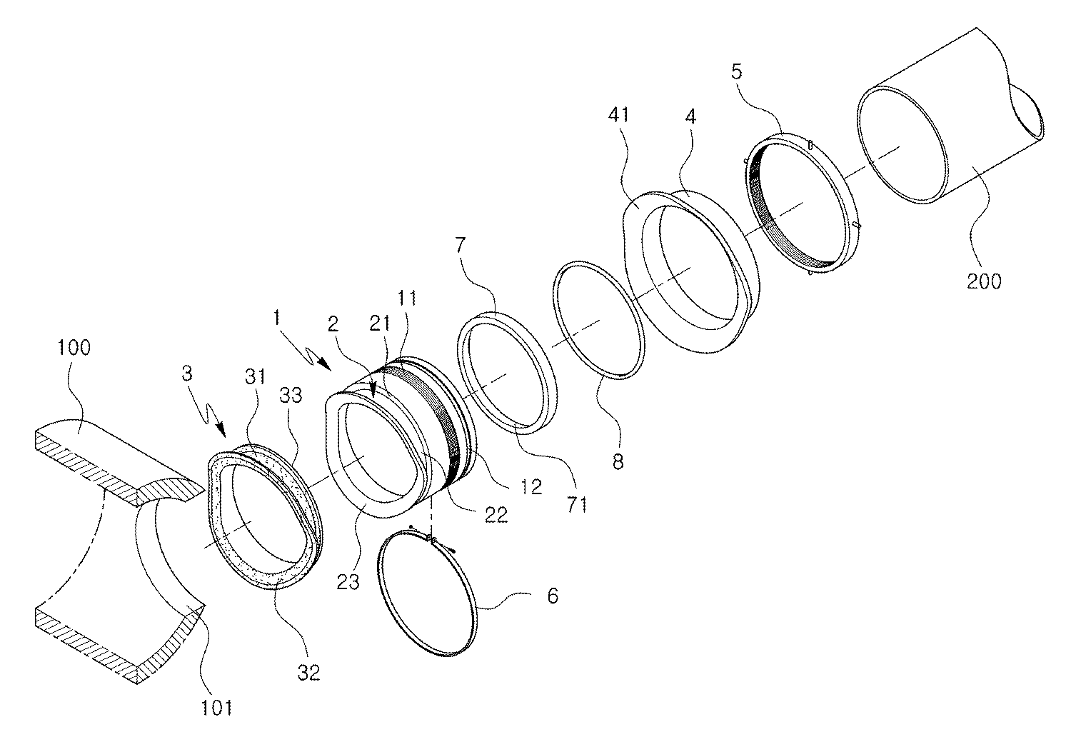
도 2는 본 발명의 하수관 연결구를 나타낸 분해 사시도.
도 3은 내부를 도시한 횡 단면도.
도 4는 본 발명에 따른 연결수단의 다른 실시예를 나타낸 단면도.
도 5는 본 발명에 따른 연결수단의 또 다른 실시예를 나타낸 개략 분해 사시도.
도 6은 본 발명에 따른 하수구 연결관의 시공과정을 나타낸 것으로,
도 6a는 주배관의 관통홀에 연결관을 삽입하는 상태를 나타낸 단면도이고,
도 6b는 주배관의 관통홀에 연결관을 관통시켜 고정한 상태를 나타낸 단면도.1 is a perspective view showing a sewer pipe connector of the present invention.
Figure 2 is an exploded perspective view showing a sewer pipe connector of the present invention.
3 is a horizontal cross-sectional view showing the inside thereof;
Figure 4 is a cross-sectional view showing another embodiment of the connecting means according to the invention.
Figure 5 is a schematic exploded perspective view showing another embodiment of the connecting means according to the present invention.
Figure 6 shows the construction process of the sewer connector according to the invention,
6A is a cross-sectional view illustrating a state in which a connector is inserted into a through hole of a main pipe;
Figure 6b is a cross-sectional view showing a state fixed through the connecting pipe through the through-hole of the main pipe.
이하, 본 발명을 첨부된 도면에 의거하여, 보다 구체적으로 설명한다. 다만, 첨부된 도면은 본 발명의 기술사상을 보다 상세하게 설명하기 위한 것일 뿐이며, 본 발명의 기술사상이 이에 한정되는 것이 아님은 당연하다.
Hereinafter, with reference to the accompanying drawings, the present invention will be described in more detail. However, the accompanying drawings are only intended to describe the technical spirit of the present invention in more detail, and the technical spirit of the present invention is not limited thereto.
도 1은 본 발명의 하수관 연결구를 나타낸 사시도이고, 도 2는 본 발명의 하수관 연결구를 나타낸 분해 사시도이며, 도 3은 내부를 도시한 횡 단면도이다. 1 is a perspective view showing a sewer pipe connector of the present invention, Figure 2 is an exploded perspective view showing a sewer pipe connector of the present invention, Figure 3 is a horizontal cross-sectional view showing the inside.
도면에 도시된 바와 같이, 본 발명의 하수관 연결구는, 주배관(100)에 형성된 관통홀(101)에 삽입되고 신축성이 없는 합성수지재로 구성되고, 후방의 외주면에는 나사부(11)가 형성되며, 나사부(11) 후방에는 둘레 함몰홈(12)이 형성된 연결관(1)과, 상기 연결관(1)의 전방 둘레에 상기 관통홀(101)의 둘레와 관통홀(101)의 둘레 전방의 대응되는 위치에 내측으로 함몰되게 형성된 둘레 함몰부(2)와, 상기 둘레 함몰부(2)에 고정되어 상기 관통홀(101)에 삽입 관통되어 연결관(1)을 주배관(100)의 관통홀(101)에 걸리게 고정하는 탄성 걸림링(3)과, 상기 주 연결관(1)의 외주면에 삽입되고 전방의 둘레 외측에는 상기 관통홀(101)의 외측 둘레에 밀착되는 전방 둘레수밀판(41)이 형성된 수밀관(4)과, 상기 나사부(11)에 체결되어 상기 수밀관(4)을 눌러주는 고정너트(5)와, 상기 둘레 함몰홈(12)에 장착되어 연결배관(200)을 연결관(1)의 후방 내부에 고정하는 밴드 클램프(6)를, 포함한다. As shown in the figure, the sewer pipe connector of the present invention is inserted into the through-
상기 둘레 함몰부(2)의 후방 둘레 수직판(21)의 후방과 연결배관(200)의 전방 단부의 사이에는, 상기 후방 둘레 수직판(21)의 내측 둘레와 연결배관(200)의 내측 둘레 사이에 형성된 단차를 줄일 수 있도록 전방의 내경이 넓고 후방의 내경이 좁은 내측 경사면을 가진 저항 감소링(7)이 더 구비되어 있는 것이다. 따라서, 상기 저항 감소링(7)을 통해 연결배관(200)에서 주배관(100)으로 하수가 원활하게 유입될 수 있도록 함으로써, 배수를 원활하게 하는 하수관 연결구를 제공하는 장점이 있다. Between the rear of the rear circumferential
상기 저항 감소링(7)의 후방과 연결배관(200)의 전방 단부의 사이에는 밀봉링(8)이 더 구비됨으로써, 수밀성을 좀 더 향상시킬 수 있는 장점도 있다.
Since the
또한, 본 발명에 따른 상기 연결관(1)은, 도 1 내지 도 3에 도시된 바와 같이, 신축성이 없는 합성수지재로 구성되어 연결배관(200)을 견고하게 주배관(100)의 관통홀(101)에 고정하는 역할을 한다. 그리고 상기 연결관(1)은 상기 주배관(100)에 형성된 관통홀(101)의 내경보다 외경이 작게 형성되어 상기 관통홀(101)에 관통 삽입되는 것이다.In addition, the connecting
상기 연결관(1)은 합성수지재로 구성되는데, 통상적으로 고강도를 유지하면서 값이 싼 PVC의 재질로 제조하는 것이 바람직하다.
The connecting
또한, 본 발명에 따른 상기 둘레 함몰부(2)는, 도 2 및 도 3에 도시된 바와 같이, 연결관(1)의 전방의 외측 둘레에 형성되어 상기 탄성 걸림링(3)을 끼워 고정하는 역할을 한다. 그리고 상기 둘레 함몰부(2)는, 상기 연결관(1)의 전방의 외측 둘레에 상기 관통홀(101)의 둘레와 관통홀(101)의 둘레 전방의 대응되는 위치에 내측으로 함몰되게 형성됨에 따라, 상기 탄성 걸림링(3)의 전방을 관통홀(101)의 내부로 돌출되게 끼울 수 있는 것이다. In addition, the
상기 둘레 함몰부(2)는, 후방의 둘레에 수직으로 세워지는 후방 둘레 수직판(21)과, 후방 둘레 수직판(21)의 내측 둘레에서 전방으로 돌출된 둘레 수평판(22)과, 둘레 수평판(22)의 전방 둘레에서 외측으로 돌출되게 형성된 전방 둘레판(23)을 포함한다. 상기 후방 둘레 수직판(21)의 전면과 둘레 수평판(22)의 외면 및 전방 둘레판(23)의 후면의 사이에 상기 탄성 걸림링(3)을 끼울 수 있는 함몰 공간이 형성되는 것이다.
The
또한, 본 발명에 따른 상기 탄성 걸림링(3)은, 도 2 및 도 3에 도시된 바와 같이, 상기 연결관(1)의 전방 둘레에 형성된 둘레 함몰부(2)에 끼워져 연결관(1)을 주배관(100)의 관통홀(101)에 끼워서 걸림을 통해 고정하는 역할을 한다. 그리고 상기 탄성 걸림링(3)은, 내측 둘레에 형성되어 상기 둘레 함몰부(2)를 구성하는 둘레 수평판(22)의 외주면에 접착되는 내측 둘레판(31)과, 내측 둘레판(31)의 전방 둘레에 상기 전방 둘레판(23)보다 더 외측으로 돌출되게 형성되어 상기 주배관(100)의 관통홀(101)에 삽입되는 과정에서는 접혀졌다가 관통홀(101)에 관통된 후 복원되면서 상기 관통홀(101)의 내부 둘레면(102)에 걸리는 유동 걸림둘레판(32)을 포함한다. In addition, the
상기 유동 걸림둘레판(32)은, 관통홀(101)에 관통된 후 복원되는 과정에서 상기 둘레 함몰부(2)를 구성하는 전방 둘레판(23)에 밀착되게 된다. 따라서 연결관(1)을 주배관(100)의 관통홀(101)에 삽입 관통시킨 상태에서 상기 유동 걸림둘레판(32)이 복원되게 한 후, 연결관(1)을 다시 후방으로 당기게 되면 유동 걸림둘레판(32)의 외측 둘레가 상기 관통홀(101)의 내부 둘레면(102)에 걸리게 된다. 그리고 상기 연결관(1)의 전방 둘레에 형성된 전방 둘레판(23)이 상기 유동 걸림둘레판(32)의 전면을 눌러 주게 되는 것이다. The flow engaging
상기 유동 걸림둘레판(32)은, 관통홀(101)의 내부 둘레면(102)에 밀착되도록 절곡되어 있다. 그리고, 상기 전방 둘레판(23)은 상기 유동 걸림둘레판(32)이 관통홀(101)의 내부 둘레면(102)에 밀착되도록 눌러 줄 수 있도록 유동 걸림둘레판(32)과 동일한 형상으로 절곡되어 있다. 그러므로 상기 탄성 걸림링(3)의 유동 걸림둘레판(32)의 형상과 연결관(1)의 전방에 형성된 전방 둘레판(23)의 형상을 서로 상응하는 동일한 형상을 이루게 함으로써 탄성 걸림링(3)의 유동 걸림둘레판(32)이 관통홀(101)의 내부 둘레면(102)에 접한 상태에서 연결관(1)의 전방 둘레판(23)이 유동 걸림둘레판(32)을 전체적으로 눌러주게 됨으로써 유동 걸림둘레판(32)은 관통홀(101)의 내부 둘레면(102)에 밀착됨으로 걸림력을 좀 더 향상시킬 수 있는 것이다. The flow locking
따라서 상기 연결관(1)을 주배관(100)의 관통홀(101)에 관통시킨 후 상기 탄성 걸림링(3)의 전방에 형성된 유동 걸림둘레판(32)을 연결관(1)의 전방 누름판의 누름력을 통해 주배관(100)의 관통홀(101)에 견고하게 걸리게 함으로써, 시공후 하수의 흐름으로 인하여 연결관(1)의 전방 둘레와 주배관(100)에 형성된 관통홀(101)의 내부 둘레면(102)의 사이가 벌어져 누수가 발생되는 것을 방지할 수 있는 장점이 있다.
Therefore, after passing through the connecting pipe (1) through the through
또한, 본 발명에 따른 상기 탄성 걸림링(3)은, 도 2 및 도 3에 도시된 바와 같이, 둘레 수평판(22)의 외측으로 돌출되어 외측의 둘레 단부가 상기 관통홀(101)의 둘레면에 밀착되는 수직 수밀판(33)을 더 포함한다. In addition, the
따라서 상기 탄성 걸림링(3)을 구성하는 둘레 수평판(22)의 외측에 주배관(100)에 형성된 관통홀(101)의 둘레면에 밀착되는 수직 수밀판(33)을 더 형성함으로써, 밀봉력을 좀 더 향상시킬 수 있는 장점도 있다.
Therefore, by further forming a vertical
한편, 본 발명의 하수관 연결구는, 도 1 내지 도 4에 도시된 바와 같이, 상기 연결배관(200)의 외주연과 연결관(1)의 내주연의 사이에는 연결수단(9)이 더 구비되는 것이다. On the other hand, the sewer pipe connector of the present invention, as shown in Figure 1 to 4, the connecting
즉 상기 연결수단(9)은, 연결배관(200)을 연결관(1)에 견고하게 고정시키면서 수밀성을 향상시키기 위한 것이다.
That is, the connecting
이에, 상기 연결수단(9)의 일 실시예는, 도 2 및 도 3에 도시된 바와 같이, 상기 연결배관(200)의 외주연에 형성된 나사부(91)와, 상기 연결관(1)의 내주연에 형성되어 상기 나사부(91)가 체결되는 탭부(92)를, 포함한다. Thus, one embodiment of the connecting
따라서, 연결배관(200)을 연결관(1)에 삽입 고정하는 과정에서 연결배관(200)을 회전시키면서 연결배관(200)의 나사부(91)를 연결관(1)의 탭부(92)에 견고하게 체결함으로써, 연결배관(200)을 연결관(1)에 견고하게 고정할 수 있는 것이다.
Therefore, while rotating the
도 4는 본 발명에 따른 연결수단의 다른 실시예를 나타낸 단면도이다. Figure 4 is a cross-sectional view showing another embodiment of the connecting means according to the invention.
본 발명에 따른 상기 연결수단(9)의 다른 실시예는, 도 4에 도시된 바와 같이, 상기 연결배관(200)의 외주연에 형성된 하나 이상의 둘레 돌출턱(93)과, 상기 연결관(1)의 내주연에 형성되어 상기 둘레 돌출턱(93)이 걸리는 하나 이상의 돌레 걸림홈(94)을 포함한다. Another embodiment of the connecting
따라서, 연결배관(200)을 연결관(1)에 삽입 고정하는 과정에서 연결배관(200)의 둘레 돌출턱(93)이 연결관(1)의 돌레 걸림홈(94)에 걸리게 함으로써, 연결배관(200)을 연결관(1)에 견고하게 고정할 수 있는 것이다.
Therefore, in the process of inserting and fixing the
도 5는 본 발명에 따른 연결수단의 또 다른 실시예를 나타낸 개략 분해 사시도이다. Figure 5 is a schematic exploded perspective view showing another embodiment of the connecting means according to the present invention.
본 발명에 따른 상기 연결수단(9)의 또 다른 실시예는, 도 5에 도시된 바와 같이, 상기 연결관(1)의 내주연에 다수로 형성된 걸림돌기(95)와; 상기 연결배관(200)의 외주연에 다수로 형성되고, 전방이 개방되어 상기 걸림돌기(95)가 삽입되는 종형홈(961)과 종형홈(961)의 후방에서 측부로 함몰 형성되어 상기 종형홈(961)에 삽입된 걸림돌기(95)를 걸리게 하는 횡형 걸림홈(962)으로 구성된 삽입 걸림홈부(96)를; 포함한다. Another embodiment of the connecting means (9) according to the present invention, as shown in Figure 5, the engaging projection (95) formed on the inner periphery of the connecting pipe (1); It is formed in the outer periphery of the connecting
따라서, 연결배관(200)을 연결관(1)에 고정하는 과정에서 연결관(1)의 걸림돌기(95)와 상기 연결배관(200)의 종형홈(961)을 일치시켜 연결배관(200)을 연결관(1)에 삽입한 다음, 연결배관(200)을 회전시키게 되면 상기 연결관(1)의 걸림돌기(95)가 상기 연결배관(200)의 횡형 걸림홈(962)에 삽입되어 걸리게 됨으로써, 연결배관(200)을 연결관(1)에 견고하게 고정할 수 있는 것이다.
Therefore, in the process of fixing the
이하, 상기와 같이 구성된 본 발명의 작용관계를 설명하면 다음과 같다. Hereinafter, the working relationship of the present invention configured as described above is as follows.
도 6은 본 발명에 따른 하수구 연결관의 시공과정을 나타낸 것으로, 도 6a는 주배관의 관통홀에 연결관을 삽입하는 상태를 나타낸 단면도이고, 도 6b는 주배관의 관통홀에 연결관을 관통시켜 고정한 상태를 나타낸 단면도이다.
6 is a view showing the construction process of the sewer connector according to the present invention, Figure 6a is a cross-sectional view showing a state in which the connecting pipe is inserted into the through hole of the main pipe, Figure 6b is fixed through the connecting pipe through the through hole of the main pipe It is sectional drawing which showed state.
도 1 내지 도 3 및 도 6에 도시된 바와 같이, 본 발명의 하수관 연결구를 시공 과정을 설명하면 다음과 같다. As shown in Figures 1 to 3 and 6, when describing the construction process of the sewer pipe connector of the present invention.
먼저 연결관(1)의 전방 둘레 형성된 둘레 함몰부(2)의 둘레 수평판(22)의 외면에 탄성 걸림링(3)의 내측 둘레판(31)을 접착제로 접착 고정한다(도 2 참조). First, the inner
다음 탄성 걸림링(3)의 전방 둘레에 고정된 연결관(1)을 주배관(100)의 관통에 삽입하게 되면, 연결관(1)의 전방 둘레에 형성된 전방 둘레판(23)은 관통홀(101)을 통과하고, 상기 탄성 걸림링(3)의 전방 둘레에 형성된 유동 걸림둘레판(32)의 외측 단부는 상기 관통링의 둘레면에 밀착되면서 유동 걸림둘레판(32)이 접히게 된다(도 6a 참조). Next, when the connecting
다음 상기와 같이 유동 걸림둘레판(32)이 접힌 상태에서 연결관(1)을 전방으로 관통되게 더 삽입하면, 상기 유동 걸림둘레판(32)의 둘레 단부가 관통홀(101)을 통과하여 관통홀(101)의 내부에 위치되면서 유동 걸림둘레판(32)이 원래의 위치로 복원되면서 펴지게 된다(도 6b 참조). Next, when the flow engaging
다음 상기 유동 걸림둘레판(32)이 복원되어 펴진 상태에서, 연결관(1)을 후방으로 당기게 되면, 상기 연결관(1)의 전방 둘레에 형성된 전방 둘레판(23)의 누름력으로 인하여 유동 걸림둘레판(32)이 주배관(100)의 내부 둘레면(102)에 밀착되어 걸리게 됨으로써, 연결관(1)을 주배관(100)의 관통홀(101)에 걸리게 고정한다(도 3 참조). Next, when the flow engaging
다음, 연결관(1)의 후방 외주연에 수밀관(4)을 삽입시킨후, 고정너트(5)의 체결을 통해 수밀관(4)을 고정한다(도 3 참조).Next, after the
다음, 연결관(1)의 내부 후방에 연결배관(200)을 삽입한 후, 연결관(1)의 외주연 후방 둘레의 둘레 함몰홈(12)에 밴드 클램프(6)를 조임으로 통해 고정함으로써, 연결관(1)의 내부에 연결배관(200)을 장착함으로써, 본 발명에 따른 하수관 연결구의 시공을 완료하는 것이다(도 3 참조). Next, after inserting the connecting
따라서, 상기 연결관(1)을 주배관(100)의 관통홀(101)에 관통시킨 후 상기 탄성 걸림링(3)의 전방에 형성된 유동 걸림둘레판(32)을 상기 연결관(1)의 전방 누름판의 누름력을 통해 주배관(100)의 관통홀(101)에 견고하게 걸리게 함으로써, 시공후 하수의 흐름으로 인하여 연결관(1)의 전방 둘레와 주배관(100)에 형성된 관통홀(101)의 내부 둘레면(102)의 사이가 벌어져 누수가 발생되는 것을 방지할 수 있는 장점이 있다. Therefore, after passing through the connecting pipe (1) through the through
이상에서 본 발명에 의한 하수관 연결구를 구체적으로 설명하였으나, 이는 본 발명의 가장 바람직한 실시양태를 기재한 것일 뿐, 본 발명이 이에 한정되는 것은 아니며, 첨부된 특허청구범위에 의해서 그 범위가 결정되어지고 한정되어진다. 또한, 이 기술분야에서 통상의 지식을 가진 자라면 누구나 본 발명의 명세서에 기재내용에 의하여 다양한 변형 및 모방을 행할 수 있는 것이나, 이 역시 본 발명의 범위를 벗어난 것이 아님은 명백하다고 할 것이다. Although the sewage pipe connector according to the present invention has been described in detail above, this is only for describing the most preferred embodiment of the present invention, and the present invention is not limited thereto, and the scope thereof is determined by the appended claims. It is limited. In addition, any one of ordinary skill in the art can make various modifications and imitations according to the description in the specification of the present invention, but it will be apparent that this is also outside the scope of the present invention.
Claims (9)
상기 연결관(1)의 전방의 외측 둘레에 상기 관통홀(101)의 둘레와 관통홀(101)의 둘레 전방의 대응되는 위치에 내측으로 함몰되게 형성되고, 후방 둘레 수직판(21)과 후방 둘레 수직판(21)의 내측 둘레에서 전방으로 돌출된 둘레 수평판(22) 및 둘레 수평판(22)의 전방 둘레에서 외측으로 돌출되게 형성된 전방 둘레판(23)으로 구성된 둘레 함몰부(2)와;
상기 둘레 함몰부(2)에 끼워지며, 내측 둘레에는 상기 둘레 수평판(22)의 외주면에 접착되는 내측 둘레판(31)이 형성되고, 내측 둘레판(31)의 전방 둘레에는 상기 전방 둘레판(23)보다 더 외측으로 돌출되어 상기 관통홀(101)에 삽입되는 과정에서는 접혀졌다가 관통홀(101)에 관통된 후 복원되면서 상기 전방 둘레판(23)에 밀착됨에 따라 상기 관통홀(101)의 내부 둘레면(102)에 걸리는 유동 걸림둘레판(32)이 형성된 탄성 걸림링(3)과;
상기 주 연결관(1)의 외주면에 삽입되고, 전방의 둘레 외측에는 상기 관통홀(101)의 외측 둘레에 밀착되는 전방 둘레수밀판(41)이 형성된 수밀관(4)과;
상기 나사부(11)에 체결되어 상기 수밀관(4)을 눌러주는 고정너트(5)와;
상기 둘레 함몰홈(12)에 장착되어 연결배관(200)을 연결관(1)의 후방 내부에 고정하는 밴드 클램프(6)를;
포함하는 것을 특징으로 하는 하수관 연결구. The outer diameter is smaller than the inner diameter of the through-hole 101 formed in the main pipe 100 penetrates the through-hole 101, the threaded portion 11 is formed on the outer peripheral surface of the rear, the peripheral recessed groove behind the screwed portion (11) A connection pipe 1 of a synthetic resin material (12) formed;
It is formed to be recessed inward at a corresponding position of the periphery of the through hole 101 and the perimeter of the through hole 101 in the outer periphery of the front of the connecting pipe 1, the rear periphery vertical plate 21 and the rear Peripheral depression 2 consisting of a perimeter horizontal plate 22 protruding forward from the inner perimeter of the perimeter vertical plate 21 and a front perimeter plate 23 protruding outward from the front perimeter of the perimeter horizontal plate 22. Wow;
An inner circumference plate 31 fitted to the circumference recess 2 and adhered to an outer circumferential surface of the circumference horizontal plate 22 is formed at an inner circumference, and the front circumference plate is formed at a front circumference of the inner circumference plate 31. In the process of protruding more outward than the 23 to be inserted into the through hole 101 is folded and then penetrated through the through hole 101 and restored to the front circumferential plate 23 as it is restored to the through hole 101 An elastic locking ring (3) formed with a flow locking circumference plate (32) caught on the inner circumferential surface (102) of the upper and lower surfaces;
A watertight tube (4) inserted into an outer circumferential surface of the main connecting tube (1) and having a front circumferential watertight plate (41) formed on the outer circumference of the front and in close contact with the outer circumference of the through hole (101);
A fastening nut (5) fastened to the screw part (11) to press the watertight tube (4);
A band clamp 6 mounted on the circumferential recessed groove 12 to fix the connection pipe 200 to the rear inside of the connection pipe 1;
Sewer pipe connector characterized in that it comprises.
상기 유동 걸림둘레판(32)은 관통홀(101)의 내부 둘레면(102)에 밀착되도록 절곡되게 형성되고,
상기 전방 둘레판(23)은 상기 유동 걸림둘레판(32)의 전면을 밀착되게 눌러 줄 수 있도록 절곡되게 형성되는 것을 특징으로 하는 하수관 연결구.
The method of claim 1,
The flow locking circumference plate 32 is bent to be in close contact with the inner circumferential surface 102 of the through hole 101,
The front circumferential plate 23 is sewer pipe connector characterized in that it is formed to be bent so as to press the front surface of the flow engaging circumference plate 32 in close contact.
상기 탄성 걸림링(3)은,
둘레 수평판(22)의 외측으로 돌출되어 외측의 둘레 단부가 상기 관통홀(101)의 둘레면에 밀착되는 수직 수밀판(33)을,
더 포함하는 것을 특징으로 하는 하수관 연결구.
The method of claim 1,
The elastic locking ring 3,
The vertical watertight plate 33 which protrudes outward of the circumferential horizontal plate 22 and adheres to the circumferential surface of the through hole 101 to the outer peripheral end thereof,
Sewer pipe connector characterized in that it further comprises.
상기 둘레 함몰부(2)의 후방 둘레 수직판(21)의 후방과 연결배관(200)의 전방 단부의 사이에는,
상기 후방 둘레 수직판(21)의 내측 둘레와 연결배관(200)의 내측 둘레 사이를 단차를 줄일 수 있도록 후방의 내경이 넓고 전방의 내경이 좁은 내측 경사면을 가진 저항 감소링(7)이 더 구비되는 것을 특징으로 하는 하수관 연결구.
The method of claim 1,
Between the rear of the rear circumferential vertical plate 21 of the circumferential depression 2 and the front end of the connecting pipe 200,
In order to reduce the step between the inner circumference of the rear circumferential vertical plate 21 and the inner circumference of the connecting pipe 200, a resistance reduction ring 7 having an inner inclined surface having a wide inner diameter of the rear and a narrow inner diameter of the front is further provided. Sewer pipe connector characterized in that it is.
상기 저항 감소링(7)의 후방과 연결배관(200)의 전방 단부의 사이에는,
밀봉링(8)이 더 구비되는 것을 특징으로 하는 하수관 연결구.
5. The method of claim 4,
Between the rear of the resistance reduction ring 7 and the front end of the connection pipe 200,
Sewer pipe connector characterized in that the sealing ring (8) is further provided.
상기 연결배관(200)의 외주연과 연결관(1)의 내주연 사이에는 연결수단(9)이 더 구비되는 것을 특징으로 하는 하수관 연결구.
6. The method according to any one of claims 1 to 5,
The sewer pipe connector, characterized in that the connection means (9) is further provided between the outer circumferential edge of the connecting pipe 200 and the inner circumferential edge of the connecting pipe (1).
상기 연결수단(9)은,
상기 연결배관(200)의 외주연에 형성된 나사부(91)와,
상기 연결관(1)의 내주연에 형성되어 상기 나사부(91)가 체결되는 탭부(92)를,
포함하는 것을 특징으로 하는 하수관 연결구.
The method according to claim 6,
The connecting means 9,
Screw portion 91 formed on the outer periphery of the connecting pipe 200,
A tab portion 92 formed at an inner circumference of the connecting pipe 1 to which the screw portion 91 is fastened,
Sewer pipe connector characterized in that it comprises.
상기 연결수단(9)은,
상기 연결배관(200)의 외주연에 형성된 하나 이상의 둘레 돌출턱(93)과,
상기 연결관(1)의 내주연에 형성되어 상기 둘레 돌출턱(93)이 걸리는 하나 이상의 둘레 걸림홈(94)을 포함하는 것을 특징으로 하는 하수관 연결구.
The method according to claim 6,
The connecting means 9,
One or more circumferential protrusions 93 formed on an outer circumference of the connection pipe 200;
Sewer pipe connector, characterized in that formed on the inner periphery of the connecting pipe (1) comprises one or more peripheral locking grooves (94) on which the circumferential projection jaw (93) is caught.
상기 연결수단(9)은,
상기 연결관(1)의 내주연에 다수로 형성된 걸림돌기(95)와;
상기 연결배관(200)의 외주연에 다수로 형성되고, 전방이 개방되어 상기 걸림돌기(95)가 삽입되는 종형홈(961)과 종형홈(961)의 후방에서 측부로 함몰 형성되어 상기 종형홈(961)에 삽입된 걸림돌기(95)를 걸리게 하는 횡형 걸림홈(962)으로 구성된 삽입 걸림홈부(96)를;
포함하는 것을 특징으로 하는 하수관 연결구.The method according to claim 6,
The connecting means 9,
A plurality of locking protrusions 95 formed on an inner circumference of the connecting pipe 1;
It is formed in the outer periphery of the connecting pipe 200, the front is opened and formed in the rear of the longitudinal groove (961) and the longitudinal groove (961) into which the engaging projection (95) is inserted into the side of the vertical groove An insertion locking groove portion 96 composed of a horizontal locking groove 962 for locking the locking protrusion 95 inserted into the 961;
Sewer pipe connector characterized in that it comprises.
Priority Applications (1)
| Application Number | Priority Date | Filing Date | Title |
|---|---|---|---|
| KR1020110116443A KR101297592B1 (en) | 2011-11-09 | 2011-11-09 | Pipe connector |
Applications Claiming Priority (1)
| Application Number | Priority Date | Filing Date | Title |
|---|---|---|---|
| KR1020110116443A KR101297592B1 (en) | 2011-11-09 | 2011-11-09 | Pipe connector |
Publications (2)
| Publication Number | Publication Date |
|---|---|
| KR20130051222A KR20130051222A (en) | 2013-05-20 |
| KR101297592B1 true KR101297592B1 (en) | 2013-08-19 |
Family
ID=48661287
Family Applications (1)
| Application Number | Title | Priority Date | Filing Date |
|---|---|---|---|
| KR1020110116443A KR101297592B1 (en) | 2011-11-09 | 2011-11-09 | Pipe connector |
Country Status (1)
| Country | Link |
|---|---|
| KR (1) | KR101297592B1 (en) |
Cited By (2)
| Publication number | Priority date | Publication date | Assignee | Title |
|---|---|---|---|---|
| KR101490720B1 (en) | 2013-11-19 | 2015-02-09 | 최승선 | Coupler of Branch Pipe in Drainage System and Coupler of Branch Pipe in Drainage System Connecting Method Using the Same |
| WO2016114592A1 (en) * | 2015-01-14 | 2016-07-21 | 종호 신하워드 | Water-resistant floor structure of prefabricated bathroom, and construction method thereof |
Citations (4)
| Publication number | Priority date | Publication date | Assignee | Title |
|---|---|---|---|---|
| KR100779987B1 (en) * | 2007-06-19 | 2007-11-28 | 주식회사천마산업사 | A pipe connector for connecting branching pipes in a main pipe |
| KR20090126156A (en) * | 2008-06-03 | 2009-12-08 | 정우통신 주식회사 | Coupling for connecting branch pipe |
| KR100959735B1 (en) * | 2008-09-02 | 2010-05-25 | 성기필 | a pipe diverging structure |
| KR20110113552A (en) * | 2010-04-09 | 2011-10-17 | 오정호 | Blind branch outlet fitting system |
-
2011
- 2011-11-09 KR KR1020110116443A patent/KR101297592B1/en active IP Right Grant
Patent Citations (4)
| Publication number | Priority date | Publication date | Assignee | Title |
|---|---|---|---|---|
| KR100779987B1 (en) * | 2007-06-19 | 2007-11-28 | 주식회사천마산업사 | A pipe connector for connecting branching pipes in a main pipe |
| KR20090126156A (en) * | 2008-06-03 | 2009-12-08 | 정우통신 주식회사 | Coupling for connecting branch pipe |
| KR100959735B1 (en) * | 2008-09-02 | 2010-05-25 | 성기필 | a pipe diverging structure |
| KR20110113552A (en) * | 2010-04-09 | 2011-10-17 | 오정호 | Blind branch outlet fitting system |
Cited By (2)
| Publication number | Priority date | Publication date | Assignee | Title |
|---|---|---|---|---|
| KR101490720B1 (en) | 2013-11-19 | 2015-02-09 | 최승선 | Coupler of Branch Pipe in Drainage System and Coupler of Branch Pipe in Drainage System Connecting Method Using the Same |
| WO2016114592A1 (en) * | 2015-01-14 | 2016-07-21 | 종호 신하워드 | Water-resistant floor structure of prefabricated bathroom, and construction method thereof |
Also Published As
| Publication number | Publication date |
|---|---|
| KR20130051222A (en) | 2013-05-20 |
Similar Documents
| Publication | Publication Date | Title |
|---|---|---|
| US11713840B2 (en) | System and method of releasably connecting pipe sections | |
| RU2515721C2 (en) | Flexible drain bellows | |
| US20050062283A1 (en) | Tank fitting and method of use | |
| KR101011018B1 (en) | Water supply and drainage pipe | |
| KR101297592B1 (en) | Pipe connector | |
| KR20130068911A (en) | Pipe connector | |
| KR101051267B1 (en) | Branch pipe socket attachment | |
| KR102137111B1 (en) | sewer pipe connection device | |
| KR20080033131A (en) | Coupler for branc pipe | |
| KR101350205B1 (en) | A coupler for connecting drain pipe | |
| KR100765851B1 (en) | A coupling apparatus for divergence of synthetic resin pipe | |
| KR101647280B1 (en) | Flange type waterproof sleeve for piping | |
| KR102286404B1 (en) | Double pipeing system into structure | |
| KR20110082365A (en) | A clamp for connecting drain pipe | |
| KR200466523Y1 (en) | Connector assemble of electric conduit | |
| KR101294759B1 (en) | Connecting structure of pipe | |
| KR200464364Y1 (en) | Connecting Parts for Between a Drainpipe and a Manhole | |
| KR101045798B1 (en) | Double wall pipe with step removal ring | |
| KR100743487B1 (en) | Connecting tube for hume | |
| KR20130039037A (en) | Pipe connector | |
| KR200435655Y1 (en) | Manhole having tightly coupling structure for drain pipe connecter | |
| CN210423705U (en) | Novel rubber seal ring | |
| KR100894896B1 (en) | Drain-pipe connection structure of manhole | |
| KR100821902B1 (en) | A socket assembly for pipe | |
| CN218386766U (en) | Waterproof splicing sleeve |
Legal Events
| Date | Code | Title | Description |
|---|---|---|---|
| A201 | Request for examination | ||
| E902 | Notification of reason for refusal | ||
| E701 | Decision to grant or registration of patent right | ||
| GRNT | Written decision to grant | ||
| FPAY | Annual fee payment |
Payment date: 20160624 Year of fee payment: 4 |
|
| FPAY | Annual fee payment |
Payment date: 20170801 Year of fee payment: 5 |
|
| FPAY | Annual fee payment |
Payment date: 20180725 Year of fee payment: 6 |
|
| FPAY | Annual fee payment |
Payment date: 20190722 Year of fee payment: 7 |