KR101260647B1 - Wireless localization method based on an efficient multilateration algorithm over a wireless sensor network and a recording medium in which a program for the method is recorded - Google Patents
Wireless localization method based on an efficient multilateration algorithm over a wireless sensor network and a recording medium in which a program for the method is recorded Download PDFInfo
- Publication number
- KR101260647B1 KR101260647B1 KR1020110082840A KR20110082840A KR101260647B1 KR 101260647 B1 KR101260647 B1 KR 101260647B1 KR 1020110082840 A KR1020110082840 A KR 1020110082840A KR 20110082840 A KR20110082840 A KR 20110082840A KR 101260647 B1 KR101260647 B1 KR 101260647B1
- Authority
- KR
- South Korea
- Prior art keywords
- estimated
- distance
- error correction
- node
- estimated position
- Prior art date
Links
Images
Classifications
-
- H—ELECTRICITY
- H04—ELECTRIC COMMUNICATION TECHNIQUE
- H04W—WIRELESS COMMUNICATION NETWORKS
- H04W64/00—Locating users or terminals or network equipment for network management purposes, e.g. mobility management
-
- G—PHYSICS
- G01—MEASURING; TESTING
- G01S—RADIO DIRECTION-FINDING; RADIO NAVIGATION; DETERMINING DISTANCE OR VELOCITY BY USE OF RADIO WAVES; LOCATING OR PRESENCE-DETECTING BY USE OF THE REFLECTION OR RERADIATION OF RADIO WAVES; ANALOGOUS ARRANGEMENTS USING OTHER WAVES
- G01S5/00—Position-fixing by co-ordinating two or more direction or position line determinations; Position-fixing by co-ordinating two or more distance determinations
- G01S5/02—Position-fixing by co-ordinating two or more direction or position line determinations; Position-fixing by co-ordinating two or more distance determinations using radio waves
- G01S5/14—Determining absolute distances from a plurality of spaced points of known location
-
- G—PHYSICS
- G01—MEASURING; TESTING
- G01S—RADIO DIRECTION-FINDING; RADIO NAVIGATION; DETERMINING DISTANCE OR VELOCITY BY USE OF RADIO WAVES; LOCATING OR PRESENCE-DETECTING BY USE OF THE REFLECTION OR RERADIATION OF RADIO WAVES; ANALOGOUS ARRANGEMENTS USING OTHER WAVES
- G01S11/00—Systems for determining distance or velocity not using reflection or reradiation
- G01S11/02—Systems for determining distance or velocity not using reflection or reradiation using radio waves
- G01S11/06—Systems for determining distance or velocity not using reflection or reradiation using radio waves using intensity measurements
-
- G—PHYSICS
- G01—MEASURING; TESTING
- G01S—RADIO DIRECTION-FINDING; RADIO NAVIGATION; DETERMINING DISTANCE OR VELOCITY BY USE OF RADIO WAVES; LOCATING OR PRESENCE-DETECTING BY USE OF THE REFLECTION OR RERADIATION OF RADIO WAVES; ANALOGOUS ARRANGEMENTS USING OTHER WAVES
- G01S5/00—Position-fixing by co-ordinating two or more direction or position line determinations; Position-fixing by co-ordinating two or more distance determinations
- G01S5/02—Position-fixing by co-ordinating two or more direction or position line determinations; Position-fixing by co-ordinating two or more distance determinations using radio waves
- G01S5/0284—Relative positioning
- G01S5/0289—Relative positioning of multiple transceivers, e.g. in ad hoc networks
Abstract
무선센서네트워크 상에서 효율적인 다변측량을 이용한 무선측위기술이 개시된다. 적어도 3개의 기준노드가 브라인드노드로부터 무선수신한 수신신호의 수신신호세기(RSS)를 이용하여 각 기준노드에서 브라인드노드까지의 추정거리를 산출한 다음, 그 산출된 추정거리를 이용하여 다변측량(multilateration)으로 브라인드노드의 추정 위치를 구한다. 그 추정위치에 포함된 에러 보정을 위해, 산출된 추정거리를 이용하되 추정위치에 가장 가까운 기준노드에 가장 큰 가중치를 적용하여 추정위치의 에러보정 방향과 에러보정 거리를 산출한다. 산출된 브라인드노드의 추정위치를 산출한 에러보정 방향과 에러보정 거리만큼 이동하여 추정위치의 에러를 보정한다. 추정거리만을 이용하여 추정위치의 에러보정을 계산이 간단하여 신속한 에러보정이 가능하며, 따라서 실시간 측위서비스에 적용할 수 있다. Disclosed is a wireless positioning technique using an efficient multivariate survey on a wireless sensor network. Calculate the estimated distance from each reference node to the blind node using the received signal strength (RSS) of the received signal wirelessly received from the blind node by at least three reference nodes, and then use the calculated estimated distance to calculate the multivariate The estimated position of the blind node is obtained by multilateration. For error correction included in the estimated position, the calculated estimated distance is used, and the error correction direction and the error correction distance of the estimated position are calculated by applying the largest weight to the reference node closest to the estimated position. The error of the estimated position is corrected by moving by the calculated error correction direction and the error correction distance. The error correction of the estimated position using only the estimated distance is simple, so that quick error correction is possible, and thus it can be applied to the real-time positioning service.
Description
본 발명은 무선센서네트워크 상에서의 무선측위방법에 관한 것으로서, 보다 상세하게는 수신신호강도(Received Signal Strength Indicator: RSSI)를 이용하여 다변측량으로 무선측위를 할 때 측위 에러를 실시간으로 정확하게 보정할 수 있는 무선측위방법에 관한 것이다. 여기서, 용어 '다변측량'은 삼변측량을 포함하는 개념으로서 3개 이상의 기준노드를 이용하여 브라인드노드의 추정위치를 추정하는 방법을 의미한다.The present invention relates to a wireless positioning method on a wireless sensor network, and more particularly, it is possible to accurately correct a positioning error in real time when performing wireless positioning by multivariate measurement using Received Signal Strength Indicator (RSSI). The present invention relates to a wireless positioning method. Here, the term 'multivariate survey' refers to a method of estimating the estimated position of a blind node using three or more reference nodes as a concept including a trilateral survey.
최근 스마트 폰에 대한 관심이 폭발적으로 증가하면서 위치기반 서비스(LBS, Location Based Service)가 큰 주목을 받고 있으며, 예컨대 증강현실, 건강관리(medical care), 홈 네트워크, 모니터링 애플리케이션과 같은 위치인식 애플리케이션들이 인기를 끌고 있다. 위치기반 서비스를 위해서는 서비스를 요구하는 사용자의 위치에 대한 측위가 정확하게 이루어져야 한다. With the recent explosion of interest in smartphones, location-based services (LBS) are receiving a lot of attention, such as location-aware applications such as augmented reality, medical care, home networks, and monitoring applications. Is gaining popularity. Location-based services require accurate positioning of the user requesting services.
잘 알려진 측위시스템으로는 모바일 내비게이션과 같은 애플리케이션을 갖춘 GPS(Global Positioning System)을 들 수 있다. 그런데 GPS방식은 옥외 환경에서는 좋은 성능을 제공하지만, 위성을 이용하여 위치정보를 얻기 때문에 실내 환경에서는 정확한 측위가 어렵다는 한계가 있다. 그러므로 GPS 시스템은 실내 채널환경이나 저비용 장치를 갖는 환경에서의 측위 시스템으로서는 적절하지 않다. A well-known positioning system is the Global Positioning System (GPS) with applications such as mobile navigation. However, the GPS method provides a good performance in the outdoor environment, but has a limitation that accurate positioning is difficult in an indoor environment because location information is obtained using satellites. Therefore, the GPS system is not suitable as a positioning system in an indoor channel environment or an environment having a low cost device.
이러한 이유로 '실내'에서의 무선 측위를 위한 기술로서, 무선랜(Wireless Local Area Network: WLAN), 초광대역(UWB, Ultra Wide Band) 통신 그리고 무선센서네트워크(Wireless Sensor Network: WSN) 등의 방식이 제안되고 많은 연구가 진행되었다. WLAN이나 UWB 시스템은 비용, 배터리, 시스템 디바이스 크기 등에 관련하여 여러 가지 한계를 가진다. 반면에, WSN은 크기가 작은 센서 노드(Sensor Node)를 많이 확보하여 측위에 이용하는 방법으로서, 저비용, 설치 용이성, 작은 사이즈, 그리고 수많은 노드들과의 연결 가능성 등의 장점을 지닌다. 실내 환경 특성상 벽, 문, 기둥 등과 같은 방해물이 많이 존재하는데, 특히 금속 재질의 소재가 분포되어 있는 경우에는 가시경로환경과 비 가시경로환경에 따라 수신신호의 세기의 차이가 매우 심하게 나타난다. WSN은 이런 환경적 요소를 트리 토폴로지 네트워크(tree topology network)를 구성하여 최적의 환경으로 만들어줄 수 있다. 많은 수의 노드를 연결할 수 있으므로 방 사이 벽들을 피해 네트워크를 구성할 수 있기 때문이다. 이러한 특징들 때문에 WSN은 실내 채널 환경에서 매우 유용한 시스템으로 평가되고 있다. 지그비(Zigbee) 기술은 IEEE 802. 15. 4 기반의 저가, 저전력, 저속의 근거리 무선통신 기술이다. 이 지그비 기술이 적용된 노드 디바이스는 매우 간단한 하드웨어 구조를 지니고 있고 하나의 네트워크에 많은 노드를 연결할 수 있어서, 이를 이용하면 초저가의 WSN을 효과적으로 구성할 수 있다.For this reason, technologies such as wireless local area network (WLAN), ultra wide band (UWB) communication, and wireless sensor network (WSN) are used for wireless positioning in an indoor environment. Many studies have been proposed and proceeded. WLAN or UWB systems have several limitations in terms of cost, battery, and system device size. WSN, on the other hand, is a method of securing many small sensor nodes and using them for positioning. The WSN has advantages such as low cost, ease of installation, small size, and connection with many nodes. Due to the characteristics of the indoor environment, there are many obstacles such as walls, doors, columns, and the like. In particular, when metal materials are distributed, the difference in the intensity of the received signal is very severe depending on the visible path environment and the non-visible path environment. The WSN can make these environmental elements optimal by constructing a tree topology network. This is because a large number of nodes can be connected so that a network can be avoided between barriers. These features make WSN a very useful system in indoor channel environments. Zigbee technology is a low-cost, low-power, low-speed, short-range wireless communication technology based on IEEE 802.11. The node device with this ZigBee technology has a very simple hardware structure and can connect many nodes to a single network, which makes it possible to effectively configure an ultra low-cost WSN.
한편, 현재까지 알려진 대표적인 무선 측위 방법으로는 범위무제한 위치추정방식(Range free approach)과 범위기반 위치추정방식(Range based approach)이 있다. 사용자의 위치를 추정함에 있어서 송신단과 수신단 사이의 거리에 대한 정보 없이 위치를 추정하는 접근 방법이 범위무제한 위치추정방식인데, 이 방법은 비용이 많이 들고 방대한 양을 기억해야 하기 때문에 실질적 타당성이 낮다. 반면에 범위기반 위치추정방식은 수신단과 송신단 사이의 거리에 대한 정보를 바탕으로 위치를 추정하는 방법으로서, 삼변측량법(trilateration estimation), 최소제곱법(least square estimation: LSE), 가중최소제곱법(weight least square estimation: WLSE) 등이 이 방식에 속한다. Meanwhile, representative wireless positioning methods known to date include a range-free location estimation method and a range-based location estimation method. In estimating the location of a user, the approach to estimating the location without information about the distance between the transmitter and the receiver is a range-limited location estimation method. This method is low in practical feasibility because it is expensive and must remember a large amount. On the other hand, the range-based position estimation method is a method of estimating the position based on the information on the distance between the receiver and the transmitter, and includes trilateration estimation, least square estimation (LSE), and weighted least square method ( weight least square estimation (WLSE)).
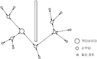
범위기반 위치추정방식에 사용되는 송신단과 수신단의 거리를 추정하는 대표적인 방법으로는 수신신호강도(Received Signal Strength Indicator: RSSI)가 있다. RSSI방식은 수신단에서 수신된 신호의 세기만을 이용하여 송수신단의 거리를 추정하는 방법으로 신호의 통과손실(Pass loss) 모델을 사용한다. 이 방법은 송수신단의 동기화와 같은 복잡한 방법을 거치지 않기 때문에 간단하지만, 신호의 특성상 비가시거리(NLOS, None Line of Sight)가 형성되어 있는 지역에서는 정확도가 떨어진다. 하지만 지그비와 같은 저가의 노드를 사용할 경우 다수의 센서 노드를 좁은 지역에 위치시켜 네트워크를 구성하면 각 노드들이 가시거리(LOS, Line of Sight)를 형성할 수 있는 환경을 만들 수 있다. 이러한 환경적 요소를 이용하여 도 1과 같이 나뭇가지 구조(Tree Topology) 네트워크를 구성하면 실내 환경에서 RSSI를 이용하여 위치를 추정할 수 있는 최적의 환경으로 만들 수 있다. A representative method for estimating the distance between a transmitter and a receiver used in the range-based position estimation method is a received signal strength indicator (RSSI). The RSSI method uses a pass loss model of the signal as a method of estimating the distance between the transmitter and the receiver using only the strength of the signal received at the receiver. This method is simple because it does not go through complicated methods such as synchronization of the transmitter and receiver, but it is inaccurate in the area where the NLB (None Line of Sight) is formed due to the characteristics of the signal. However, when using low-cost nodes such as ZigBee, a network can be constructed by placing a large number of sensor nodes in a small area so that each node can form a line of sight (LOS). Using such environmental factors, a tree topology network as shown in FIG. 1 may be used to make an optimal environment for estimating a location using RSSI in an indoor environment.
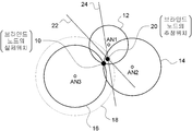
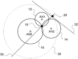
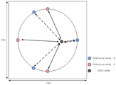
RSSI와 같은 방법으로 추정된 송수신단의 거리를 이용하여 사용자의 위치를 추정하는 기본적인 방법으로 삼변측량이 널리 이용된다. 삼변측량을 이용한 정확한 측위를 위해서는 위치를 알고 있는 노드(이하, '기준노드'(reference node)라 함)를 중심으로 하고, RSSI 방법으로 추정된 거리를 반지름으로 하는 3개의 원들이 교직선을 형성해야 하고, 이러한 교직선들이 도 2와 같이 하나의 교점을 형성해야 한다. 그런데 송수신단의 거리를 추정함에 있어 큰 에러가 포함되면, 거리가 매우 크거나 작게 추정되어 1개의 원이 다른 원과 완전히 분리되거나, 1개의 원이 다른 원을 완전히 포함하는 경우 즉, 도 3과 같이 3개의 원이 교직선을 형성하지 못하는 경우가 실질적인 환경에서는 발생할 수도 있다. 1개의 원이 다른 원과 완전히 분리되어 있거나, 다른 원을 완전하게 포함하는 경우 그렇지 않은 경우에 비해 상대적으로 큰 위치 추정 에러를 갖게 된다. 그러므로 RSSI 방법에 기반한 삼변측량은 이러한 측위 에러를 현저히 개선하는 방법이 모색될 필요가 있다. Trilateral surveying is widely used as a basic method of estimating a user's position using the estimated distance of a transmitter / receiver in the same manner as RSSI. For accurate positioning using trilateration, three circles centered around nodes whose location is known (hereinafter referred to as 'reference nodes') and whose distances are estimated by the RSSI method are radial. And these intersection lines should form one intersection as shown in FIG. However, if a large error is included in estimating the distance of the transmitting and receiving end, the distance is estimated to be very large or small so that one circle is completely separated from another circle, or one circle completely includes another circle, Likewise, the case where three circles do not form a straight line may occur in a practical environment. If one circle is completely separated from another circle or completely includes another circle, it will have a relatively large position estimation error as compared to the case otherwise. Therefore, trilateration based on RSSI method needs to find a way to significantly improve these positioning errors.
종래에는 측위 에러를 보정하기 위해, 삼변측량을 이용한 추정 위치를 산출하기에 앞서, RSSI를 이용하여 구한 추정거리에 포함된 에러 보정을 먼저 하였고, 그 에러 보정된 추정거리를 이용하여 삼변측량을 하여 추정 위치를 구하였다. 삼변측량에 이용된 추정거리가 에러를 보정한 것이므로 삼변측량으로 구한 추정 위치에 대한 에러 보정은 더 이상 수행하지 않고 최종적으로 얻고자 하는 추정 위치로 확정하였다. 그런데 추정거리의 에러보정에 의거한 종래의 무선 측위방법은 알고리즘이 복잡하고 반복적(recursive)인 연산이 많고, 특히 측위의 정확도를 높이기 위해서는 연산량이 더욱 증대하여 문제가 있어서 실시간 무선측위 서비스에 적용하는 데 부적합하였다. Conventionally, in order to correct a positioning error, prior to calculating an estimated position using trilateration, an error correction included in an estimated distance obtained using RSSI is first performed, and then trilateration is performed using the error corrected estimated distance. The estimated position was obtained. Since the estimated distance used for the trilateration is an error correction, the error correction for the estimated position obtained by the trilateration is no longer performed and the final estimated position is determined. However, the conventional wireless positioning method based on the error correction of the estimated distance has many algorithms that are complicated and recursive, and in particular, in order to increase the accuracy of the positioning, the computational amount is increased so that the problem is applied to the real-time wireless positioning service. It was inadequate.
기존의 가중 최소제곱 추정법(Weight Least Square Estimation: WLSE)에 따른 무선 측위 방식은 채널 요소인 채널지수(channel exponent)와 로그노말 쉐도우잉 (lognormal shadowing)의 크기를 이용하여 보정 값을 정하기 때문에 그 한계가 있다. 왜냐하면 채널 요소 2개를 정확히 아는 것이 매우 힘들기 때문이다. 그렇기에 실용적인 방법이 못된다. The conventional wireless positioning method based on the weighted least square estimation (WLSE) has its limitation because the correction value is determined by using the channel exponent and the lognormal shadowing, which are channel elements. There is. This is because it is very difficult to know exactly two channel elements. That is not a practical way.
본 발명은 RSSI을 이용하여 다변측량으로 브라인드노드의 위치 추정을 함에 있어서 브라인드노드와 기준노드들 간의 추정거리만을 이용한 간단한 계산을 통해 추정위치의 측위에러를 실시간으로 정확하게 보정할 수 있으며, 그렇기 때문에 실시간 무선측위서비스에도 적용할 수 있는 무선측위방법과 이를 실현하기 위한 프로그램이 기록된 기록매체를 제공하는 것을 목적으로 한다. In the present invention, in the estimation of the position of a blind node by multivariate survey using RSSI, the positioning error of the estimated position can be accurately corrected in real time through a simple calculation using only the estimated distance between the blind node and the reference node. An object of the present invention is to provide a radiometric method applicable to a radiolocation service and a recording medium on which a program for realizing the same is recorded.
상기와 같은 목적을 달성하기 위한 본 발명의 일 측면에 따르면, 위치를 알고 있는 적어도 3개의 기준 노드와 위치를 알고자 하는 1개의 브라인드노드, 그리고 무선측위서버를 적어도 포함하는 무선 네트워크에서 상기 무선측위서버에 의해 실행되는 무선측위방법 있어서, 상기 무선측위서버에서, 상기 적어도 3개의 기준노드가 브라인드노드로부터 무선수신한 수신신호의 수신신호세기(RSS)를 상기 적어도 3개의 기준노드로부터 제공받아 상기 적어도 3개의 기준노드 각각에서 상기 브라인드노드까지 적어도 3개의 추정 거리를 산출하는 제1 단계; 상기 무선측위서버에서, 산출된 상기 적어도 3개의 추정 거리를 이용하여 다변측량(multilateration)으로 상기 브라인드노드의 추정 위치를 산출하는 제2단계; 상기 무선측위서버에서, 산출된 상기 추정위치에 포함된 에러 보정을 위해, 상기 제1단계에서 산출한 상기 추정거리를 이용하되 상기 추정위치에 가장 가까운 기준노드를 중심으로 상기 추정위치의 에러보정 방향과 에러보정 거리를 산출하는 제3단계; 및 상기 무선측위서버에서, 상기 제2단계에서 산출한 상기 브라인드노드의 추정위치를 상기 제3단계에서 산출한 상기 에러보정 방향과 상기 에러보정 거리만큼 이동한 위치를 보정된 추정위치로 산출하는 제4단계를 구비하는 것을 특징으로 하는 무선 측위 방법이 제공된다.According to an aspect of the present invention for achieving the above object, the wireless positioning in a wireless network including at least three reference nodes that know the location, one blind node to know the location, and at least a wireless positioning server A wireless positioning method executed by a server, the wireless positioning server, wherein the at least three reference nodes receive a received signal strength (RSS) of a received signal wirelessly received from a blind node from the at least three reference nodes; Calculating at least three estimated distances from each of the three reference nodes to the blind node; Calculating, by the radiolocation server, an estimated position of the blind node by multilateration using the calculated at least three estimated distances; In the wireless positioning server, an error correction direction of the estimated position is used based on the reference node closest to the estimated position using the estimated distance calculated in the first step for correcting the error included in the estimated position. A third step of calculating an error correction distance; And calculating, by the radio positioning server, a position at which the estimated position of the blind node calculated in the second step is moved by the error correction direction and the error correction distance calculated in the third step as a corrected estimated position. Provided is a wireless positioning method comprising four steps.
상기 무선 측위 방법에 있어서, 상기 제3단계에서 상기 에러보정 방향은, 상기 제2단계에서 산출된 상기 추정위치에서 가장 가까운 기준노드로 향하는 제1각도벡터![]()
![]()
![]()
![]()


여기서, 상기 가중치 α와 β는 그 값이 각각 1인 것이 보다 바람직하다. Here, it is more preferable that the weights α and β each have a value of 1.
상기 무선 측위 방법에 있어서, 상기 제3단계에서 상기 에러보정 거리는, 상기 추정위치로부터 가장 가까운 기준노드의 추정거리 disti와 상기 추정 위치에서 상기 가장 가까운 기준노드까지의 거리 distiep를 각각 산출하는 제3-3단계; 및 아래 식을 이용하여 에러보정용 거리 CompD를 산출하는 제3-4단계 (가중치 γ는 추정위치에서 가장 가까운 기준노드로부터 CRLB에 의거하여 정해지는 값이며, i는 기준노드를 특정 하는 값이며, CRLBi는 기준노드(i)의 추정하고자 하는 거리에 대한 최소의 편차(variance)임)의 실행을 통해 산출되는 것이 바람직하다. In the wireless positioning method, in the third step, the error correction distance is calculated by calculating an estimated distance dist i of a reference node closest to the estimated position and a distance dist iep from the estimated position to the nearest reference node, respectively. Steps 3-3; And a 3-4 step of calculating the error correction Comp distance D by using the following equation: (weight γ is a value determined on the basis of the CRLB from the closest reference node at the estimated position, i is a value that specifies a reference node, The CRLB i is preferably calculated through the execution of a minimum deviation of the distance to be estimated of the reference node i).
![]()
![]()
여기서, 상기 가중치 γ의 값은 1인 것이 보다 바람직하다. Here, it is more preferable that the value of the said weight ( gamma ) is 1.
상기 무선 측위 방법에 있어서, 상기 제2단계는 3개의 추정거리를 이용하는 삼변측량(trilateration)으로 상기 브라인드노드의 추정위치를 산출하는 것이 바람직하다. In the wireless positioning method, the second step is to calculate the estimated position of the blind node by trilateration using three estimated distances.
상기 무선 측위 방법은, 상기 제2단계를 수행하기 전에, 상기 제1단계에서 산출된 상기 3개의 추정거리 중에서 한계치 이상의 에러가 존재하는 경우에는 에러보정을 수행하는 제5단계를 더 포함하는 것이 바람직하다. The wireless positioning method may further include a fifth step of performing error correction when an error equal to or larger than a threshold value exists among the three estimated distances calculated in the first step before performing the second step. Do.
바람직하게, 상기 제5단계는, 상기 적어도 3개의 기준노드 각각을 중심으로 각 기준노드에 대응하는 추정거리를 반지름으로 하는 적어도 3개의 추정거리 원을 각각 구하는 제5-1단계; 및 상기 적어도 3개의 추정거리 원들 중에서 가장 넓은 범위(range)를 갖는 추정거리 원이 나머지 두 개의 추정거리 원을 포함하여 교점을 만들 수 없을 때, 상기 가장 넓은 범위를 갖는 추정거리 원이 가장 좁은 범위를 갖는 추정거리 원에 접하도록 상기 가장 넓은 범위를 갖는 추정거리 원의 추정거리를 감축 보정하는 제5-2단계를 구비한다.
Preferably, the fifth step may further include: obtaining each of at least three estimated distance circles each having a radius of an estimated distance corresponding to each reference node with respect to each of the at least three reference nodes; And when the estimated distance circle having the widest range among the at least three estimated distance circles cannot make an intersection including the remaining two estimated distance circles, the estimated distance circle having the widest range is the narrowest range. And reducing and correcting the estimated distance of the estimated distance circle having the widest range so as to contact the estimated distance circle having the maximum distance.
한편, 본 발명의 상기 목적을 달성하기 위한 다른 측면에 따르면, 위치를 알고 있는 적어도 3개의 기준 노드와 위치를 알고자 하는 1개의 브라인드노드, 그리고 무선측위서버를 적어도 포함하는 무선 네트워크에서, 무선측위 프로그램이 기록되어 있고 상기 무선측위서버로 읽을 수 있는 기록매체로서, 상기 무선측위 프로그램은, 상기 무선측위서버에서, 상기 적어도 3개의 기준노드가 브라인드노드로부터 무선수신한 수신신호의 수신신호세기(RSS)를 상기 적어도 3개의 기준노드로부터 제공받아 상기 적어도 3개의 기준노드 각각에서 상기 브라인드노드까지 적어도 3개의 추정 거리를 산출하는 제1 기능; 상기 무선측위서버에서, 산출된 상기 적어도 3개의 추정 거리를 이용하여 다변측량(multilateration)으로 상기 브라인드노드의 추정 위치를 산출하는 제2 기능; 상기 무선측위서버에서, 산출된 상기 추정위치에 포함된 에러 보정을 위해, 상기 제1 기능을 통해 산출한 상기 추정거리를 이용하되 상기 추정위치에 가장 가까운 기준노드를 중심으로 이용하여 상기 추정위치의 에러보정 방향과 에러보정 거리를 산출하는 제3 기능; 및 상기 무선측위서버에서, 상기 제2 기능을 통해 산출한 상기 브라인드노드의 추정위치를 상기 제3 기능을 통해 산출한 상기 에러보정 방향과 상기 에러보정 거리만큼 이동한 위치를 보정된 추정위치로 산출하는 제4 기능을 구비하는 것을 특징으로 하는 무선측위 프로그램이 기록된 기록 매체가 제공된다.On the other hand, according to another aspect for achieving the above object of the present invention, in a wireless network comprising at least three reference nodes that know the location, one blind node to know the location, and at least a wireless positioning server, A recording medium in which a program is recorded and can be read by the wireless positioning server, wherein the wireless positioning program includes a received signal strength (RSS) of a received signal wirelessly received from the blind node by the at least three reference nodes in the wireless positioning server. Receiving at least three reference distances from the at least three reference nodes and calculating at least three estimated distances from each of the at least three reference nodes to the blind node; A second function of calculating, at the radiolocation server, an estimated position of the blind node by multilateration using the calculated at least three estimated distances; In the radiolocation server, for the error correction included in the estimated position, the estimated position calculated using the estimated distance calculated through the first function is used as the center of the reference node closest to the estimated position. A third function of calculating an error correction direction and an error correction distance; And calculating, by the wireless positioning server, a position at which the estimated position of the blind node calculated by the second function is moved by the error correction direction and the error correction distance calculated by the third function as a corrected estimated position. There is provided a recording medium on which a radiolocation program is recorded, which has a fourth function.
본 발명에 의하면, 다변측량을 이용한 무선측위를 함에 있어서 상대적으로 큰 추정에러를 포함하는 추정 거리를 찾아내어 그 추정 거리에 포함된 에러를 감소시켜 브라인드노드의 추정 위치의 정확도를 크게 개선할 수 있다. According to the present invention, it is possible to greatly improve the accuracy of the estimated position of a blind node by finding an estimated distance including a relatively large estimated error and reducing the error included in the estimated distance in performing radio positioning using multivariate survey. .
기존의 WLSE의 추정 알고리즘은 램덤 요소와 채널 지수(channel exponent)를 정확히 알아야 가중치(weight)를 줄 수 있으며, 추정 위치의 에러 보정을 위해 반복적인 연산을 수행해야 한다. 이에 비해, 본 발명은 각 기준노드에서 브라인드노드까지의 추정거리에 대한 비교만으로 위치를 보정할 수 있기 때문에 보다 위치추정을 위한 계산이 간단하며 매우 효율적으로 수행될 수 있다. 그러므로 본 발명의 무선측위방법은 실시간 위치 추적에 매우 효율적인 방법이 될 수 있다. Existing WLSE's estimation algorithm needs to know the random element and channel exponent correctly to give weight, and it is necessary to perform repetitive calculation for error correction of estimated position. In contrast, the present invention can correct the position only by comparing the estimated distance from each reference node to the blind node, so that the calculation for the position estimation can be performed more simply and very efficiently. Therefore, the radiolocation method of the present invention can be a very efficient method for real-time location tracking.
본 발명은 또한 모든 노드의 개수에서 보다 나은 측위의 정확도를 보인다. 특히 가장 작은 3개의 노드를 이용했을 때 종래방법들에 비해 획기적인 성능 개선 효과를 볼 수 있다. The present invention also shows better positioning accuracy in the number of all nodes. In particular, when the smallest three nodes are used, the performance improvement can be remarkable compared to the conventional methods.
도 1은 RSSI를 이용하여 위치를 추정할 수 있는 최적의 환경을 설명하기 위한 네트워크의 나뭇가지 구조를 도시하며,
도 2는 삼변측량의 교차 케이스(Intersection Case)의 예를 도시하며,
도 3은 삼변측량의 비교차 케이스(None Intersection Case)의 예를 도시하며,
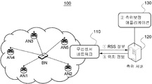
도 4는 본 발명에 따른 에러보정 측위 방법을 실행하기 위한 무선 측위 시스템(100)의 개략적인 구성을 도시하며,
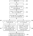
도 5는 본 발명에 따른 에러보정 측위방법 설명하기 위한 흐름도이며,
도 6은 모든 가능한 경우의 삼변측량의 예를 보여주며,
도 7은 크래머-라오 하한식(Cramer-Rao Lower Bound: CRLB)이 추정 거리와 쉐도우잉 요소에 따라 결정되는 것을 보여주는 그래프이며,
도 8의 (a)와 (b)는 에러보정 각도(방향)와 에러보정 거리를 각각 산출하는 방법을 도식적으로 나타낸 것이고, 도 8의 (c)는 산출된 에러보정 각도(방향)와 에러보정 거리를 적용하여 삼변측량으로 추정한 위치를 보정하는 방법을 도식적으로 나타낸 것이다.
도 9는 본 발명의 성능을 측정하기 위한 IEEE 802.15.4a 실내 채널 시뮬레이션 모델을 도시한다. FIG. 1 illustrates a tree branch structure for explaining an optimal environment for estimating a location using RSSI.
2 shows an example of an intersection case of trilateration,
3 shows an example of a non-intersection case of trilateration,
4 shows a schematic configuration of a
5 is a flowchart illustrating an error correction positioning method according to the present invention;
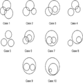
6 shows examples of trilateration in all possible cases,
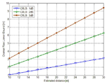
7 is a graph showing that the Cramer-Rao Lower Bound (CRLB) is determined according to the estimated distance and the shadowing factor.
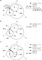
(A) and (b) of FIG. 8 schematically show a method of calculating the error correction angle (direction) and the error correction distance, respectively, and FIG. 8 (c) shows the calculated error correction angle (direction) and the error correction. It shows the method of correcting the position estimated by trilateration by applying distance.
9 illustrates an IEEE 802.15.4a indoor channel simulation model for measuring the performance of the present invention.
이하에서는 첨부한 도면을 참조하여 본 발명을 실시할 수 있도록 보다 구체적으로 설명할 것이다. Hereinafter, with reference to the accompanying drawings will be described in more detail to enable the present invention.
본 발명이 제안하는 무선측위방법은 수신신호강도(RSS) 값을 이용하여 브라이드 노드로부터 각 기준노드까지의 거리를 추정하고, 그 추정거리 값을 이용하여 삼변측량으로 브라인드노드의 위치를 추정한다. In the proposed wireless positioning method, the distance from the braid node to each reference node is estimated using the received signal strength (RSS) value, and the position of the blind node is estimated by trilateration using the estimated distance value.
(1) 실내 경로 손실 모델(1) indoor path loss model
RSS는 각 기준노드가 브라인드노드로부터 수신한 각각의 패킷에 대하여 측정될 수 있다. 송신된 신호의 세기는 송신단과 수신단의 거리에 비례하게 감소된다는 것이 알려져 있다. 쉐도우잉의 랜덤한 특성 때문에 수신 신호의 세기는 특정한 평균값을 갖고, 그 평균값을 중심으로 가우시안 분포를 따르게 된다(송신단과 수신단의 거리가 일정한 경우). 가우시안 모델을 사용할 경우, i 번째 기준노드(수신단)에서 j 번째 브라인드노드(송신단)로부터 수신한 신호의 세기(RSS의 앙상블의 평균값) ![]()
![]()

여기서, PO는 짧은 기준 거리 dO(통상적으로 1m 임)에서 수신된 신호의 세기를 의미하며, n은 환경에 따라 변하는 경로손실지수(path loss exponent)를 의미하고 일반적으로 2~4 사이의 값을 가지며, ![]()
![]()
![]()
![]()
위와 같이 RSSI를 이용하여 거리를 추정하는 데 있어서 에러가 발생하는 이유는 크게 3가지가 있다. 하드웨어와 관련된 에러, 거리추정 알고리즘의 한계 그리고 환경적인 요소이다. 하드웨어와 관련된 에러는 일반적인 ZigBee소자에서 약 3dB ~ 4dB정도의 에러가 발생한다고 알려져 있다. 실제 채널에서, 다중경로 신호 페이딩(다양한 경로를 통과한 신호들이 각각 다른 크기와 다른 페이저를 갖고 수신단에 들어오면서 해당 주파수에 보강간섭 또는 상쇄간섭으로 합쳐져서 생기는 에러유발현상)과 쉐도우잉(환경적인 요인으로 인해 수신되는 신호에 손실이 발생하는 현상)은 그 측정된 RSS의 에러를 유발하는 2 가지 환경적인 에러요인이다. 다중경로 신호 페이딩은 주파수-선택적 페이딩을 야기하므로, 이런 류의 페이딩 효과는 확산 스펙트럼(spread spectrum)을 이용하여 줄일 수 있다. WSN이 주파수-선택적 효과들은 직접 시퀀스 확산 스펙트럼(direct sequence spread spectrum)을 이용할 수 있기 때문에, 주파수-선택적 효과들은 감소된다고 볼 수 있다. 그러므로 환경적인 에러들은 벽, 나무, 의자 등과 같은 것들에 의해 일어나는 쉐도우잉 효과에 의해 야기되는 것이 주가 된다. 그러므로 무선 측위에서 RSS를 이용하여 거리를 추정할 때는 멀티패스 페이딩에 대한 영향은 무시하고, 쉐도우잉의 영향만을 고려한다. 장애물들에 의한 쉐도우잉 효과들은 랜덤 방식으로 모델화된다. 위의 식에서 RSSI(dBm)은 수신 신호 세기를 이용하여 측정된 값이므로 1m에서의 전력손실인 PO와 경로손실지수 n값은 실험측정실험을 통해 검증해야한다. 이는 수신신호세기로부터 정확한 거리를 추정하기 위해 반드시 선행되어야 하는 작업이다.There are three main reasons for error in estimating distance using RSSI. Errors related to hardware, limitations of distance estimation algorithms, and environmental factors. Errors related to hardware are known to cause errors of about 3dB to 4dB in general ZigBee devices. In a real channel, multipath signal fading (errors caused by the signals passing through the various paths, each having a different size and different phaser, entering the receiver at the frequency combined with constructive or destructive interference) and shadowing (environmental factors) Loss of the received signal) are two environmental error factors that cause errors in the measured RSS. Since multipath signal fading results in frequency-selective fading, this kind of fading effect can be reduced by using a spread spectrum. Since the WSN can use the direct sequence spread spectrum, the frequency-selective effects can be seen to be reduced. Therefore, environmental errors are mainly caused by shadowing effects caused by things such as walls, trees, chairs, and the like. Therefore, when estimating the distance using RSS in radio location, the effect on multipath fading is ignored and only shadowing is considered. Shadowing effects by obstacles are modeled in a random manner. In the above equation, RSSI (dBm) is measured by using the received signal strength. Therefore, the power loss P O and the path loss index n value at 1m should be verified through experimental measurement experiments. This is a task that must be performed to estimate the correct distance from the received signal strength.
(2) 삼변측량(Trilateration)(2) Trilateration
삼변측량 방법은 추정된 거리를 바탕으로 위치를 추정하는 방법으로서, 위치를 알고 있는 3개의 고정 노드(기준노드)를 이용하여 위치를 알고자 하는 노드(브라인드노드)의 위치를 추정하는 방법이다. 모든 노드들이 비용 상의 고려 때문에 전방향성 안테나를 가지고 있고, 각 고정 노드는 상기 경로 손실 모델을 이용하여 그 자신의 위치와 브라인드노드의 위치 간의 거리 ![]()
![]()
로그-노말 쉐도우잉을 갖는 RSSI로 표현되는 RSS에 관하여, 추정거리 ![]()
![]()
![]()
![]()
![]()
![]()
![]()
![]()
![]()
![]()
여기서, xi와 yi (단, i=1,2,3)는 기준노드의 직교 좌표 지점이고, xr과 yr 은 동일한 좌표계에서 브라인드노드의 추정 위치를 나타내며, ![]()
![]()
식 (2)를 이용하여 다음과 같은 연산을 수행하면 브라인드노드의 추정 위치를 구할 수 있다. 식 (2)는 3개의 기준노드의 위치(원의 중심)와 3개의 추정거리 ![]()
![]()
![]()
![]()
![]()
![]()
그 두 직선의 방정식을 연립하여 풀면 그 해가 바로 브라인드노드의 추정 위치가 된다. If you solve the equations of the two straight lines, the solution is the estimated position of the blind node.
구체적으로, 위의 식을 행렬형태로 표현하면 아래와 같다. Specifically, the above equation is expressed as a matrix as follows.
![]()
![]()
여기서 ![]()
![]()
![]()
![]()
![]()
![]()
![]()
![]()
결과적으로 브라인드노드의 위치는 최소제곱법(least square method)을 이용하여 추정된다.As a result, the location of the blind node is estimated using the least square method.
삼변측량을 기하학적으로 설명하면 아래와 같다. 3개의 기준노드(AN1, AN2, AN3)와 브라인드노드간의 거리가 정확하게 추정되면, 도 2와 같이 3개의 원(12, 14, 16)이 1개의 점(10)에서 만나게 된다. 이렇게 1개의 점에서 3개의 원이 만나는 경우는 정확한 거리측정에 따른 매우 정확한 위치추정이 이루어지는 경우이다. 하지만 기준노드와 브라인드노드 간의 추정 거리에 에러가 포함되어 있으면, 3개의 원이 1개의 점에서 만나지 않는다. 예컨대 기준노드 AN3에서 브라인드노드까지의 추정거리가 부정확한 경우, 점선(18)과 같이 원이 형성되는 경우가 발생한다. 이러한 경우 기존의 삼변측량법에 따르면, 도시된 바와 같이 2개의 원 (12, 18)과 또 다른 2개의 원(14, 18)이 형성하는 두 직선(22, 24)의 교점(20)이 추정된 위치가 된다. 2개의 원이 교차하지 않도록 거리가 추정되면(즉, 하나의 원(12)이 다른 하나의 원(26)에 포함되도록 추정되면), 그 두 원의 방정식을 풀면 하나의 직선(32)의 방정식이 얻어진다. 그러면 도 3과 같이 그 직선(32)과 또 다른 두 원(12, 14)의 두 교점을 지나는 직선(30)의 교점이 브라인드노드의 추정 위치가 된다.The trilateration is described geometrically as follows. If the distance between the three reference nodes (AN1, AN2, AN3) and the blind node is accurately estimated, as shown in FIG. 2, three
이하에서 설명하는 본 발명의 무선측위방법은 브라인드노드까지의 추정거리를 구하는 데 이용되는 기준노드를 적어도 3개를 이용한다. 3개를 이용하는 경우에는 삼변측량법으로, 4개 이상을 이용하는 경우에는 다변측량법(multilateration)으로 각 기준노드에서 브라인드노드까지의 추정거리를 구한다. 다변측량법은 삼변측량법의 확장으로서, 최소제곱법(least square method)을 이용하여 각 기준노드에서의 추정거리를 구하고, 그 구한 추정거리를 이용하여 최소제곱법으로 브라인드노드의 추정위치를 산출하는 점에서는 동일하며, 이미 잘 알려진 것이므로 설명을 생략한다.The wireless positioning method of the present invention described below uses at least three reference nodes used to obtain an estimated distance to a blind node. If three are used, triangulation is used, and if four or more are used, the estimated distance from each reference node to a blind node is obtained by multilateration. The multivariate method is an extension of the trilateration method, and uses the least square method to obtain an estimated distance from each reference node, and uses the estimated distance to calculate the estimated location of the blind node using the least square method. Are the same and are already well known, so the description is omitted.
(3) 본 발명이 제안하는 효율적인 에러보정기능을 갖는 무선측위방법(3) Wireless positioning method with efficient error correction function proposed by the present invention
브라인드노드의 위치 추정을 함에 있어서, 발생하는 에러의 요인들에 대해 살펴본다. 브라인드노드에 대한 측위 에러는 위에서 언급한 바와 같이 환경적인 요인들에 의해 발생한다. 전력 차원에 있어서, RSS는 쉐도우잉 요소에 의해 영향을 받는다. 따라서 RSSI는 측정값에 관한 노이즈 범위들을 갖는데, 그 노이즈 범위들은 삼변측량을 이용하여 세 개의 추정 원들의 교점을 형성하지 않을 수 있다. 도 6은 모든 가능한 경우의 삼변측량의 예를 보여준다.In the estimation of the position of the blind node, the causes of error occurring are discussed. The positioning error for the blind node is caused by environmental factors as mentioned above. In terms of power, RSS is influenced by the shadowing factor. Thus RSSI has noise ranges for the measured values, which may not form the intersection of three estimate circles using trilateration. 6 shows examples of trilateration in all possible cases.
케이스 1에서의 측위 에러는 다른 케이스에 비하여 낮다. 그것은 모든 추정 거리들이 작은 편차를 가지기 때문이다. 이것은 아래 식 (3)으로 나타내지는 크래머-라오 하한식(CRLB)에 의해 정의된다. 신호세기는 dB 스케일이며 이를 거리로 바꿀 때 지수 함수로 표현되며, 이는 뒤의 쉐도우잉 요소가 로그-노말 분포를 따르기 때문이다. 따라서 신호세기를 통해 거리를 추정하게 되면 이 또한 확률적 모델로 바뀌게 되는데, 추정한 거리의 확률적 분포, 즉 편차(variance) 값을 CRLB로 정의할 수 있다. CRLB는 바이어스 되지 않은 추정기의 편차에 대한 하한(a lower bound)을 설정한다.The positioning error in
![]()
![]()
여기서, ![]()
![]()
![]()
![]()

p(RSS;d)는 d를 파라미터로서 갖는 RSS의 확률밀도함수이며, 다음과 같이 정의된다.p (RSS; d) is a probability density function of RSS having d as a parameter, and is defined as follows.

따라서 추정 거리의 하한값의 편차를 다음과 같이 계산할 수 있다. Therefore, the deviation of the lower limit of the estimated distance can be calculated as follows.
![]()
![]()
식 (6)의 ![]()
![]()
그렇지만, 쉐도우잉 요소는 기준노드들이 유사한 평면에 있을 때에는 그 기준노드 전부는 서로 유사할 것이다. 가장 먼 추정거리를 갖는 기준노드는 정확도를 떨어뜨린다. 반면에 가장 짧은 추정 거리를 갖는 기준노드는 다른 모든 기준노드들보다 가장 신뢰할만한 노드이다. 그러므로 에러 보상 방법을 만들고 도 6과 같은 기하학적 문제들을 완화하기 위해, 두 개의 기준노드 즉, 가장 짧은 추정거리를 갖는 기준노드와 가장 긴 추정거리를 갖는 기준노드를 고려하는 것이 바람직하다.However, the shadowing elements will all be similar to each other when the reference nodes are in a similar plane. The reference node with the farthest estimated distance degrades accuracy. On the other hand, the reference node with the shortest estimated distance is the most reliable node than all other reference nodes. Therefore, in order to make an error compensation method and to mitigate geometrical problems as shown in FIG. 6, it is desirable to consider two reference nodes, that is, a reference node having the shortest estimated distance and a reference node having the longest estimated distance.
이런 관점에 따라, 위치 추정의 노이즈 범위에 의해 야기되는 기하학적 문제들을 보상하기 위해 본 발명은 개선된 에러보정 기능을 갖는 위치 추정방법(이하, '에러보정 측위방법'이라 함)을 제안한다. 도 4는 본 발명에 따른 에러보정 측위 방법을 실행하기 위한 무선 측위 시스템(100)의 개략적인 구성을 도시한다. 무선 측위 시스템(100)은 위치를 알고 있는 적어도 3개의 기준노드(AN1, AN2, AN3)와 위치를 알고자 하는 측위대상 단말기 즉, 브라인드노드(BN)를 포함하는 무선 네트워크(110)와, 측위보정 애플리케이션(130)을 실행하여 무선 네트워크(110)로부터 제공된 수신신호강도(Received Signal Strength: RSS) 정보를 처리하여 브라인드노드(BN)의 위치 정보를 정확하게 산출하는 무선네트워크 측위서버(120)를 포함한다. 그 측위서버(120)에서 실행되는 측위보정 애플리케이션(130)은 본 발명에 따른 '에러보정 측위방법'을 구현한 것이다. 이 측위보정 애플리케이션(130) 프로그램은 CD, DVD, 하드디스크, 비휘발성 메모리 등과 같은 컴퓨터 가독형 기록매체에 기록되고, 측위서버(120)와 같은 컴퓨터 장치에 연결되어 실행될 수 있다. According to this aspect, the present invention proposes a position estimation method (hereinafter referred to as an 'error correction positioning method') with an improved error correction function in order to compensate for geometric problems caused by the noise range of the position estimation. 4 shows a schematic configuration of a
도 5는 본 발명에 따른 에러보정 측위방법 설명하기 위한 흐름도이다. 본 발명에 따른 에러보정 측위방법은 추정거리 산출단계, 기하학적 에러 보정단계, 삼변측량 단계, 에러보정 각도 산출 단계, 에러보정 거리 산출단계를 포함한다. 그런데 기하학적 에러 보정단계는 필요한 경우에만 수행하면 된다. 이하에서 설명되는 에러보정 측위방법은 측위서버(120)가 측위보정 애플리케이션(130)을 실행하는 것을 통해 수행된다. 구체적으로 설명하면, 추정거리 산출단계는 먼저 브라인드노드의 위치를 추정하기 위해 측위서버(120)가 무선네트워크(110)의 각 기준노드(AN1, AN2, AN3, ...)로부터 RSS 값을 제공받는다(S10 단계). 각 RSS 값은 각 기준노드(AN1, AN2, AN3, ...)가 브라인드노드(BN)로부터 무선 수신한 신호로부터 결정되는 값이다. RSS 값이 입력받은 측위서버(120)는 그 RSS 값들 중에서 브라인드노드(BN)와 이 브라인드노드(BN)의 위치 추정을 위한 기준노드인 3개 이상의 기준노드를 선택한다(S12 단계). 통상 신호 세기가 가장 좋은 3-5개 정도의 노드를 기준노드로 이용한다. 이하에서는 3개의 기준노드(AN1, AN2, AN3)를 선택한 경우를 예로 하여 설명한다. 측위서버(120)는 기준노드를 선택한 다음에는, RSS 값을 이용하여 3개의 기준노드(AN1, AN2, AN3) 각각에서 브라인드노드(BN)까지의 거리를 추정한다(S14 단계). 각 기준노드(AN1, AN2, AN3)와 브라인드노드(BN) 간의 3개의 추정 거리는 위에서 설명한 식 (1-2)를 이용하여 구한다. 5 is a flowchart illustrating an error correction positioning method according to the present invention. The error correction positioning method according to the present invention includes an estimation distance calculation step, a geometric error correction step, a trilateral measurement step, an error correction angle calculation step, and an error correction distance calculation step. However, the geometric error correction step only needs to be performed when necessary. The error correction positioning method described below is performed by the
브라인드노드(BN)로부터 세 개의 기준노드까지의 추정거리가 얻어지면, 그 추정거리를 이용하여 삼변측량으로 브라인드노드(BN)의 위치를 추정한다(S18 단계). 즉, 그 세 개의 추정거리에 따른 원의 방정식을 구하여 브라인드노드(BN)의 위치를 추정할 수 있다. When the estimated distances from the blind node BN to the three reference nodes are obtained, the position of the blind node BN is estimated by trilateration using the estimated distance (step S18). That is, the position of the blind node BN may be estimated by obtaining a circle equation according to the three estimated distances.
그런데 삼변측량으로 추정 위치를 구하기에 앞서, S14단계에서 구한 추정거리의 에러를 보정할 필요가 있는 경우에는 그 에러를 보정하는 처리를 수행한다. 앞서 설명한 것처럼 무선 센서를 이용한 위치 측위 방식은 신호 세기를 이용하여 거리를 추정하고 이에 따른 원의 방정식을 구하여 위치를 추정한다. RSS를 이용한 거리추정 방식은 주변 환경에 따른 쉐도우잉과 반사파에 의해서 정확한 거리를 추정하기 힘들어서 삼변측량 시 도 6과 같은 10가지 케이스를 만들어 낸다. 예컨대 케이스 1의 경우는 다른 케이스에 비해서 보다 낮은 에러를 발생시킨다. 이 점은 앞에서 살펴본 CRLB로부터 그 근거를 알 수 있다(도 7 참조). CRLB는 확률적 모델을 이용하여 추정하고자 하는 요소의 최소 편차(variance) 값을 나타내는 값으로 (확률적 모델: 경로손실 식(1)로부터 추정거리 d의 최소 편차 지수) 식 (3) ~ (6)의 순서로 구할 수 있다. CRLB 값을 근거로 살펴보면 추정 거리의 크기가 작으면 작을수록 그 값의 편차(variance)는 더 작다는 것을 알 수 있다. 따라서 추정거리가 작으면 작을수록 더 신뢰할 수 있는 값이라고 할 수 있다(이 점이 추정위치로부터 가장 가까운 기준노드에 가중치를 더 크게 부여하는 이유인데, 이에 관해서는 후술한다). 본 발명은 이러한 점을 이용하여 에러 보정을 수행한다. However, before it is necessary to correct the error of the estimated distance obtained in step S14, the process of correcting the error is performed before obtaining the estimated position by trilateration. As described above, the positioning method using the wireless sensor estimates the distance by using the signal strength and estimates the position by obtaining the circle equation accordingly. In the distance estimation method using RSS, it is difficult to estimate the exact distance by shadowing and reflected waves according to the surrounding environment, thus creating ten cases as shown in FIG. For example,
에러 보정의 첫 번째는 S14 단계에서 산출된 각 기준노드(AN1, AN2, AN3)와 브라인드노드(BN) 간의 거리 추정값에 대한 에러 보정이다(S16 단계). 추정 거리에 대한 에러 보정은 기하학적 에러보정법(Geometric method)을 이용하여 수행할 수 있다. 기하학적 에러보정법은 거리가 멀리 떨어져 있는 기준노드의 추정 원(식(2))이 다른 기준노드의 추정 원을 포함하는 상태가 발생할 때 크게 추정된 원을 가장 작은 원에 접하도록 추정 거리를 보정하는 방법이다. 달리 표현하면, 각 기준노드가 갖는 추정거리 원들 중에서 가장 넓은 범위(range)를 갖는 추정거리 원(추정거리를 반지름으로 하는 원)이 다른 기준노드가 갖는 추정거리 원을 포함할 경우(즉, 추정거리 원들이 교점을 만들 수 없을 때), 큰 추정 범위를 갖는 추정거리 원(즉, 다른 추정거리 원들을 내포하는 추정거리 원)을 가장 작은 추정거리 원에 맞춰줌(matching)으로써 측위 에러를 보상하는 방법이다. 이를 식으로 표현하면 다음 식 (7)과 같다.The first of the error corrections is an error correction for the distance estimation value between each of the reference nodes AN1, AN2, and AN3 and the blind node BN calculated in step S14 (step S16). Error correction for the estimated distance may be performed using a geometric error correction method. Geometric error correction corrects the estimated distance so that the large estimated circle is in contact with the smallest circle when the estimated source (Equation (2)) of the reference node with a long distance includes the estimated circle of another reference node. That's how. In other words, if the estimated distance circle (circle whose estimated distance is the radius) having the widest range among the estimated distance circles of each reference node includes the estimated distance circle of another reference node (that is, the estimated Compensate for positioning errors by matching distance sources with large estimated ranges (ie, estimated distance circles containing other estimated distance circles) to the smallest estimated distance circle when the distance circles cannot intersect. That's how. This is expressed by the following equation (7).

여기서, di와 dj는 i와 j의 노드 번호를 갖는 추정거리이고, distij는 기준노드 i와 j 사이의 거리이다. i는 추정 위치로부터 가장 멀리 떨어져 있는 기준노드의 번호이며, j는 추정 위치로부터 가장 가까이 있어 범위가 가장 작게 나타나는 기준노드의 번호이다.Here, d i and d j are estimated distances having node numbers i and j, and dist ij is a distance between reference nodes i and j. i is the number of the reference node that is farthest from the estimated position, and j is the number of the reference node that is closest to the estimated position and has the smallest range.
이 기하학적 에러 보정방법은 삼변측량 시 실제로 에러 없이 추정할 경우 하나의 추정 원은 다른 추정 원과 적어도 하나의 교점을 갖는다는 특징을 고려하여, 가장 편차(variance)가 작은 원에 맞춰주어 에러를 보정함으로써 매우 간단하게 에러를 보정할 수 있다. 그러므로 이 기하학적 보정방법은 도 6의 케이스 3, 6, 7, 8, 9, 10처럼 큰 원이 다른 작은 원들을 포함하는 경우에 적용될 수 있다. 선택된 기준노드들에 대해 산출된 추정거리들이 도 6의 케이스 3, 6, 7, 8, 9, 10 중 어느 한 가지에 해당하는 원들을 구성하는 경우에는 식 (7)을 적용하여 추정거리에 대한 에러보정을 수행하면 되고, 그 밖의 케이스에 해당하면 단계 16의 기하학적 에러보정 절차는 수행하지 않는다. 이 기하학적 보정방법은 에러보정을 매우 간단하게 할 수 있으면서도 우수한 성능(정확도 개선_을 보여준다는 점이 장점이다.This geometric error correction method corrects the error by fitting the circle with the smallest variation, taking into account the characteristic that one estimation circle has at least one intersection point with another estimation source when the trilateral survey is actually estimated without errors. The error can be corrected very simply. Therefore, this geometric correction method can be applied to a case where a large circle such as
위와 같이 과정(S14, S16 단계)을 통해 에러 보정이 적용된 또는 에러 보정이 필요 없는 추정거리가 얻어지면, 그 구한 추정거리와 기준노드의 알려진 좌표값을 식(2)에 적용하여 앞서 언급한 삼변측량을 이용하여 브라인드노드(BN)의 위치를 추정하는 단계(S18 단계)를 수행한다. When the estimated distance to which the error correction is applied or the error correction is not obtained through the above processes (steps S14 and S16) is obtained, the above-mentioned three sides are applied by applying the obtained estimated distance and the known coordinate value of the reference node to equation (2). The step of estimating the position of the blind node BN is performed by using the survey (step S18).
브라인드노드의 위치 추정값이 구해지면 그 위치 추정값을 이용하여 그 추정 위치에 포함되어 있는 에러를 보정할 크기를 계산한다. 추정 위치에 포함된 에러를 보정하는 것은 그 추정 위치를 에러를 최소화하는 방향으로 에러 최소화에 필요한 거리만큼 이동하는 것과 같다. 그러므로 에러보정 각도(방향) 산출(S20, S22 단계)과 에러보정 거리 산출(S24, S26 단계)을 수행한다. 도 8의 (a)와 (b)는 에러보정 각도(방향)와 에러보정 거리를 각각 산출하는 방법을 도식적으로 나타낸 것이고, 도 8의 (c)는 산출된 에러보정 각도(방향)과 에러보정 거리를 적용하여 삼변측량으로 추정한 위치를 보정하는 방법을 도식적으로 나타낸 것이다. 이를 참조하여 에러보정 각도(방향)과 에러보정 거리를 산출하여 추정위치를 보정하는 방법을 설명하기로 한다.When the position estimate of the blind node is obtained, the position estimate is used to calculate a size to correct an error included in the estimated position. Correcting an error included in the estimated position is equivalent to moving the estimated position by a distance necessary to minimize the error in the direction of minimizing the error. Therefore, the error correction angle (direction) calculation (steps S20 and S22) and the error correction distance calculation (steps S24 and S26) are performed. (A) and (b) of FIG. 8 schematically show a method of calculating the error correction angle (direction) and the error correction distance, respectively, and FIG. 8 (c) shows the calculated error correction angle (direction) and error correction. It shows the method of correcting the position estimated by trilateration by applying distance. A method of correcting the estimated position by calculating the error correction angle (direction) and the error correction distance will be described with reference to this.
먼저, 에러보정 각도(방향)를 정하는 방법을 설명한다. 에러보정 각도(방향)를 정하기 위해서 각 기준노드와 추정 위치의 좌표값들을 이용하여 각 기준노드(AN1, AN2, AN3)에서 추정위치(EP)로 향하는 직선의 위상(각도)을 구한다(S20 단계). 아래 식 (8)이 이를 위한 것이다.First, a method of determining the error correction angle (direction) will be described. In order to determine the error correction angle (direction), a phase (angle) of a straight line from each reference node (AN1, AN2, AN3) to the estimated position (EP) is obtained using the coordinate values of each reference node and the estimated position (step S20). ). Equation (8) below is for this purpose.

여기서, ![]()
![]()
'추정위치(EP)에서 가장 가까운 위치의 기준노드(AN1)를 중심으로 그 기준노드(AN1)에 관한 추정거리를 반지름으로 하는 원)'(이하, '최근거리 원'이라 함)에 가중치를 주기 위해 추정위치(EP)를 이동(보정)하는 것이기 때문에, 추정위치(EP)에서 가장 가까운 기준노드(AN1)로 향하는 제1방향 즉, 제1각도벡터![]()
![]()
![]()
![]()

여기서 가중치 α와 β는 각각 아래 식 (10)으로 결정되는 값이다. dist c 와 dist f 는 추정위치에서 가장 가까운 기준노드와 가장 먼 기준노드에서의 추정거리를 각각 나타낸다. The weights α and β are values determined by

발명자가 시뮬레이션을 해본 바에 의하면, 가중치α와 β의 값을 각각 1로 적용할 때, 즉 선택된 두 기준노드 AN1과 AN3에 대하여 구한 제1각도벡터 ![]()
![]()
![]()
![]()
한편, 에러보정을 위한 거리 CompD를 산출하기 위해서 먼저 S18 단계에서 구한 추정 위치에서부터 가장 가까운 기준노드까지의 거리 distiep를 산출한다(S24 단계). Meanwhile, in order to calculate the distance Comp D for error correction, first, the distance dist iep from the estimated position obtained in step S18 to the nearest reference node is calculated (step S24).
그런 다음, 그 '추정 위치로부터 가장 가까운 기준노드의 추정거리 disti'에 소정의 가중치 γ를 적용한 값과 '추정 위치에서부터 가장 가까운 기준노드까지의 거리 distiep' 간의 차이를 산출한다. 그 거리 차이가 바로 얻고자 하는 에러보정용 거리 CompD이다(S26 단계). 아래 식 (11)은 이를 위한 것이다. Then, the difference between the value of applying the predetermined weight γ to the estimated distance dist i of the reference node closest to the estimated position and the distance dist iep from the estimated position to the nearest reference node is calculated. The distance difference is the error correction distance Comp D which is to be obtained immediately (step S26). Equation (11) below is for this.
![]()
![]()
여기서, 가중치 γ는 추정위치에서 가장 가까운 기준노드로부터 CRLB에 의거하여 정해지는 값이다. Here, the weight γ is a value determined based on the CRLB from the reference node closest to the estimated position.
본 발명자가 시뮬레이션 해본 바에 의하면, 가중치 γ의 값이 1일 때 구한 보정거리가 가장 적정한 값으로 판단된다. According to the inventors' simulation, the correction distance obtained when the value of the weight γ is 1 is determined to be the most appropriate value.
이처럼, 추정위치에 포함된 에러를 보정하기 위한 보정 방향과 보정 거리를 결정함에 있어서, 기준노드들의 추정거리 및/또는 추정위치와 각 기준노드들까지의 거리 정보만을 이용하므로 연산이 아주 간단하여 신속한 연산이 가능하다. As described above, in determining the correction direction and the correction distance for correcting the error included in the estimated position, only the estimated distance and / or the estimated position of the reference nodes and the distances to the respective reference nodes are used, so the calculation is very simple and quick. Operation is possible.
CRLB에 따라서 가장 가까운 거리에 있을 경우 확률적으로 가장 정확한 값을 갖기 때문에 즉, 식 (6) 때문에, 가장 가까운 기준노드가 가장 신뢰할 수 있는 거리를 갖는다. 그러므로 측위 에러를 보정하기 위해서는 삼변측량으로 얻어진 추정 위치를 가장 가까운 기준노드의 추정거리 원으로 그 추정위치에 맞추는 것(즉, 옮기는 것)이 필요하다. 이 방법의 결점은 그것이 가장 가까운 기준노드로부터 그 추정 거리의 정확도에 의존할 뿐이라는 점이다. 따라서 쉐도우잉이 큰 환경에서는 방법의 성능이 떨어진다.The closest reference node has the most reliable distance because it is stochasticly the most accurate value when it is at the closest distance according to CRLB, that is, because of equation (6). Therefore, in order to correct the positioning error, it is necessary to fit (ie, move) the estimated position obtained by the trilateration to the estimated position circle of the nearest reference node. The drawback of this method is that it only depends on the accuracy of its estimated distance from the nearest reference node. The performance of the method is therefore poor in high shadowing environments.
이러한 과정을 통해 각각 산출된 에러보정 각도 CompA과 에러보정 거리 CompD를 이용하여 S18단계에서 구한 추정 위치의 좌표를 이동함으로써, 그 추정 위치에 포함되어 있는 에러가 보정될 수 있다(S28 단계). 에러보정 각도 CompA은 에러 보정의 방향을 정해주고, CompD는 길이와 부호 (즉, 플러스 또는 마이너스)를 결정한다.The error included in the estimated position may be corrected by shifting the coordinates of the estimated position obtained in step S18 using the error correction angle Comp A and the error corrected distance Comp D calculated through the above process (step S28). . Error correction angle Comp A determines the direction of error correction, and Comp D determines the length and sign (ie plus or minus).
그리고 S18단계에서 삼변측량으로 구한 브라인드노드의 추정 위치를 에러보정을 위한 각도 CompA와 거리 CompD에 따라 이동한 좌표가 바로 브라인드노드의 최종 추정 위치의 좌표로 확정된다(S30단계).The coordinates obtained by shifting the estimated position of the blind node obtained by the trilateration at step S18 according to the angle Comp A and the distance Comp D for error correction are immediately determined as the coordinates of the final estimated position of the blind node (step S30).
이렇게 에러보정을 위한 각도 CompA와 거리 CompD를 이용하여 추정 위치를 보정하면, 기하학적 에러보정 방법으로 보정하기 힘든 다른 케이스에 대해서 좀 더 정확한 위치를 추정할 수 있다. If the estimated position is corrected using the angle Comp A and the distance Comp D for error correction, a more accurate position can be estimated for other cases that are difficult to correct by the geometric error correction method.
이상에서는 3개의 기준노드를 이용하여 측위 에러를 보정하는 방법을 설명하였지만, 이용 가능한 기준노드의 개수는 4개 이상이 될 수도 있다. 그 경우 4개 이상의 추정거리가 얻어지고, 그 4개 이상의 추정거리를 다변측량법(multilateration)을 이용하여 브라인드노드의 추정위치를 산출하면 된다.In the above, the method of correcting the positioning error using three reference nodes has been described, but the number of available reference nodes may be four or more. In this case, four or more estimated distances may be obtained, and the estimated positions of the blind nodes may be calculated using the multilateration of the four or more estimated distances.
본 발명자는 도 9에 도시된 것과 같이 IEEE 802.15.4a 실내 채널 모델을 따르는 시뮬레이션을 통해 본 발명의 성능을 측정해보았다. 시뮬레이션 필드는 사무실 환경(10m, 10m)이고, 기준노드들은 고정되어 있으며 그들의 위치를 제공한다. 기준노드의 개수는 각 시뮬레이션 시나리오에 따라 바뀌며, 기준노드는 시뮬레이션 필드의 중심으로부터 동일한 거리를 보장하기 위해 반경 3m의 원에 균일하게 위치된다. The present inventors measured the performance of the present invention through a simulation according to the IEEE 802.15.4a indoor channel model as shown in FIG. The simulation field is an office environment (10m, 10m) and the reference nodes are fixed and provide their location. The number of reference nodes varies with each simulation scenario, and the reference nodes are uniformly located in a circle with a radius of 3 m to ensure the same distance from the center of the simulation field.
IEEE 802.15.4a 실내 채널 모델은 경로 손실 모델, 그리고 이의 파라미터 예컨대 실내 사무실 환경에서 경로 손실 지수, 쉐도우잉 요소(예를 들어 2에서 4dB)와 같은 파라미터를 나타낸다. 시뮬레이션은 기준노드들의 개수와 쉐도우잉 요소에서의 차이점들이라는 두 가지 요소(factors)를 보여준다. The IEEE 802.15.4a indoor channel model represents a path loss model and its parameters such as path loss index, shadowing factor (e.g. 2 to 4 dB) in indoor office environment. The simulation shows two factors: the number of reference nodes and the differences in shadowing factors.
쉐도우잉 요소가 2dB이고 채널 지수 값이 2.2001인 환경에서, 100,000회 시뮬레이션을 통해 얻은 평균값에 의하면, 본 발명은 최소제곱법(LSE)에 비해 약 40~43% 정도의 성능(측위 정확도)의 개선을 보임을 확인할 수 있었다. 심지어 엄청난 연산을 필요로 하는 WLSE 방법에 비해서도 더 나은 성능을 보임을 확인할 수 있었다. 무엇보다도, 기준노드의 개수가 증가하더라도 LSE법이나 WLSE법은 본 발명의 방법에 비해서는 성능이 떨어지며, 본 발명의 무선 측위방법은 기준노드의 수에 상관없이 항상 LSE 방법이나 WLSE 방법보다 성능이 더 좋게 나오는 것을 확인할 수 있었다. In an environment where the shadowing factor is 2dB and the channel index value is 2.2001, the average value obtained through 100,000 simulations shows that the present invention improves the performance (positioning accuracy) by about 40 to 43% compared to the least square method (LSE). I could see that. Even better performance was achieved compared to the WLSE method, which requires a lot of computation. Above all, even if the number of reference nodes is increased, the LSE method and the WLSE method are inferior to the method of the present invention, and the wireless positioning method of the present invention always performs better than the LSE method or the WLSE method regardless of the number of reference nodes. I could see that it came out better.
본 발명에 의한 에러 보정 방법은 기준노드를 3개만 이용하는 삼변측량을 통해 위치 추정을 하는 경우에도 매우 좋은 성능을 보인다. 즉, 최소의 기준노드의 개수로 좋은 결과를 얻을 수 있다. 본 발명은 또한 추정거리만을 이용하여 추정 위치의 보정값을 계산하기 때문에 계산이 매우 간단하여 실시간으로 수행할 수 있다. 그러므로 위치기반 서비스에 적용할 수 있는 실용적인 방법이 될 수 있다. The error correction method according to the present invention shows very good performance even when the position estimation is performed through trilateration using only three reference nodes. In other words, good results can be obtained with the minimum number of reference nodes. The present invention also calculates the correction value of the estimated position using only the estimated distance so that the calculation is very simple and can be performed in real time. Therefore, it can be a practical method that can be applied to location-based services.
본 발명은 RSSI를 이용한 무선측위를 필요로 하는 분야에 널리 적용될 수 있으며, 특히 실시간 무선측위서비스에 적용될 수도 있다.The present invention can be widely applied to a field requiring radio positioning using RSSI, and in particular, can be applied to a real-time radio positioning service.
100: 무선 측위 시스템 110: 무선센서네트워크
120: 측위서버 130: 측위보정 애플리케이션100: wireless positioning system 110: wireless sensor network
120: positioning server 130: positioning correction application
Claims (12)
상기 무선측위서버에서, 상기 적어도 3개의 기준노드가 브라인드노드로부터 무선수신한 수신신호의 수신신호세기(RSS)를 상기 적어도 3개의 기준노드로부터 제공받아 상기 적어도 3개의 기준노드 각각에서 상기 브라인드노드까지 적어도 3개의 추정 거리를 산출하는 제1 단계;
상기 무선측위서버에서, 산출된 상기 적어도 3개의 추정 거리를 이용하여 다변측량(multilateration)으로 상기 브라인드노드의 추정 위치를 산출하는 제2단계;
상기 무선측위서버에서, 산출된 상기 추정위치에 포함된 에러 보정을 위해, 상기 제1단계에서 산출한 상기 추정거리를 이용하되 상기 추정위치에서 가장 가까운 기준노드를 중심으로 상기 추정위치의 에러보정 거리를 산출함과 동시에, 상기 추정위치에서 가장 가까운 기준노드와 가장 먼 기준노드를 이용하여 상기 추정위치의 에러보정 방향을 산출하는 제3단계; 및
상기 무선측위서버에서, 상기 제2단계에서 산출한 상기 브라인드노드의 추정위치를 상기 제3단계에서 산출한 상기 에러보정 방향과 상기 에러보정 거리만큼 이동한 위치를 보정된 추정위치로 산출하는 제4단계를 구비하며,
상기 제1단계는, 산출된 상기 적어도 3개의 추정거리를 반지름으로 하는 적어도 3개의 추정거리 원들 중에서, 가장 큰 추정거리 원이 나머지 추정거리 원들과 교차하지 않고 상기 나머지 추정거리 원들을 내부에 포함하는 경우, 상기 가장 큰 추정거리 원이 가장 작은 추정거리 원에 접하도록 상기 가장 큰 추정거리 원의 추정거리를 감축 보정하는 단계를 포함하는 것을 특징으로 하는 무선 측위 방법.In a wireless positioning method executed by the wireless positioning server in a wireless network, the wireless network comprising at least three reference nodes that know a location, one blind node that wants to know the location, and a wireless location server.
In the wireless positioning server, the at least three reference nodes receive a received signal strength (RSS) of the received signal wirelessly received from the blind node from the at least three reference nodes to each of the at least three reference nodes. Calculating at least three estimated distances;
Calculating, by the radiolocation server, an estimated position of the blind node by multilateration using the calculated at least three estimated distances;
In the wireless positioning server, the error correction distance of the estimated position is used based on the reference node closest to the estimated position using the estimated distance calculated in the first step to correct the error included in the estimated position. Calculating a error correction direction of the estimated position using a reference node farthest from the reference node closest to the estimated position; And
A fourth position for calculating the estimated position of the blind node calculated in the second step by the wireless positioning server as the corrected estimated position by moving the error correction direction calculated by the third step and the error correction distance; With steps,
The first step includes, among the calculated at least three estimated distance circles having the radius of the at least three estimated distances, the largest estimated distance circle does not intersect the remaining estimated distance circles and includes the remaining estimated distance circles therein. And reducing and correcting the estimated distance of the largest estimated distance circle so that the largest estimated distance circle contacts the smallest estimated distance circle.
상기 제2단계에서 산출된 상기 추정위치에서 가장 가까운 기준노드로 향하는 제1각도벡터
아래 식들을 이용하여 에러보정 방향(각도) CompA를 구하는 제3-2단계 (여기서, 가중치 α와 β는 아래 식으로 결정되는 값이며, dist c 와 dist f 는 추정위치에서 가장 가까운 기준노드와 가장 먼 기준노드에서의 추정거리를 각각 나타냄)의 실행을 통해 산출되는 것을 특징으로 하는 무선 측위 방법.


A first angle vector directed toward the reference node closest to the estimated position calculated in the second step;
Steps 3 and 2, where the error correction direction (angle) Comp A is calculated using the following equations, where weights α and β are values determined by the following equations, and dist c and dist f are the reference nodes closest to the estimated positions. Radio-location method, the estimated distance from the farthest reference node).
상기 추정위치로부터 가장 가까운 기준노드의 추정거리 disti와 상기 추정 위치에서 상기 가장 가까운 기준노드까지의 거리 distiep를 각각 산출하는 제3-3단계; 및
아래 식을 이용하여 에러보정용 거리 CompD를 산출하는 제3-4단계 (가중치 γ는 추정위치에서 가장 가까운 기준노드로부터 CRLB에 의거하여 정해지는 값이며, i는 기준노드를 특정 하는 값이며, CRLBi는 기준노드(i)의 추정하고자 하는 거리에 대한 최소의 편차(variance)임)의 실행을 통해 산출되는 것을 특징으로 하는 무선 측위 방법.
Calculating an estimated distance dist i of the reference node nearest to the estimated position and a distance dist iep from the estimated position to the nearest reference node, respectively; And
The steps 3 and 4 for calculating an error correction Comp distance D by using the following equation: (weight γ is a value determined on the basis of the CRLB from the closest reference node at the estimated position, i is a value that specifies a reference node, CRLB i is calculated through the execution of a minimum variation of the distance to be estimated of the reference node (i).
상기 무선측위 프로그램은,
상기 무선측위서버에서, 상기 적어도 3개의 기준노드가 브라인드노드로부터 무선수신한 수신신호의 수신신호세기(RSS)를 상기 적어도 3개의 기준노드로부터 제공받아 상기 적어도 3개의 기준노드 각각에서 상기 브라인드노드까지 적어도 3개의 추정 거리를 산출하는 제1 기능;
상기 무선측위서버에서, 산출된 상기 적어도 3개의 추정 거리를 이용하여 다변측량(multilateration)으로 상기 브라인드노드의 추정 위치를 산출하는 제2 기능;
상기 무선측위서버에서, 산출된 상기 추정위치에 포함된 에러 보정을 위해, 상기 제1 기능을 통해 산출한 상기 추정거리를 이용하되 상기 추정위치에서 가장 가까운 기준노드를 중심으로 이용하여 상기 추정위치의 에러보정 거리를 산출함과 동시에, 상기 추정위치에서 가장 가까운 기준노드와 가장 먼 기준노드를 이용하여 상기 추정위치의 에러보정 방향을 산출하는 제3 기능; 및
상기 무선측위서버에서, 상기 제2 기능을 통해 산출한 상기 브라인드노드의 추정위치를 상기 제3 기능을 통해 산출한 상기 에러보정 방향과 상기 에러보정 거리만큼 이동한 위치를 보정된 추정위치로 산출하는 제4 기능을 구비하며,
상기 제1 기능은, 산출된 상기 적어도 3개의 추정거리를 반지름으로 하는 적어도 3개의 추정거리 원들 중에서, 가장 큰 추정거리 원이 나머지 추정거리 원들과 교차하지 않고 상기 나머지 추정거리 원들을 내부에 포함하는 경우, 상기 가장 큰 추정거리 원이 가장 작은 추정거리 원에 접하도록 상기 가장 큰 추정거리 원의 추정거리를 감축 보정하는 기능을 포함하는 것을 특징으로 하는 무선측위 프로그램이 기록된 기록 매체. In a wireless network that includes at least three reference nodes that know a location, one blind node that wants to know a location, and at least a wireless location server, a radio location program is recorded and can be read by the wireless location server. ,
The radio location program,
In the wireless positioning server, the at least three reference nodes receive a received signal strength (RSS) of the received signal wirelessly received from the blind node from the at least three reference nodes to each of the at least three reference nodes. A first function of calculating at least three estimated distances;
A second function of calculating, at the radiolocation server, an estimated position of the blind node by multilateration using the calculated at least three estimated distances;
In the radiolocation server, the estimated distance calculated by the first function is used to correct the error included in the estimated position, and the reference position closest to the estimated position is used as the center of the estimated position. A third function of calculating an error correction distance and calculating an error correction direction of the estimated position using a reference node farthest from the reference node closest to the estimated position; And
Calculating, by the radio positioning server, a position at which the estimated position of the blind node calculated by the second function is moved by the error correction direction and the error correction distance calculated by the third function as a corrected estimated position; Has a fourth function,
The first function includes, among the calculated at least three estimated distance circles having the radius of the at least three estimated distances, the largest estimated distance circle does not intersect the remaining estimated distance circles and includes the remaining estimated distance circles therein. And reducing and correcting the estimated distance of the largest estimated distance circle so that the largest estimated distance circle contacts the smallest estimated distance circle.


(여기서,
(here,
(여기서, disti는 상기 추정위치로부터 가장 가까운 기준노드의 추정거리이고, distiep는 상기 추정 위치에서 상기 가장 가까운 기준노드까지의 거리이며, 가중치 γ는 추정위치에서 가장 가까운 기준노드로부터 CRLB에 의거하여 정해지는 값이며, i는 기준노드를 특정하는 값이며, CRLBi는 기준노드(i)의 추정하고자 하는 거리에 대한 최소의 편차(variance)임)10. The recording medium of claim 9, wherein the error correction distance is an error correction distance Comp D obtained by using the following equation.
Where dist i is the estimated distance of the reference node nearest to the estimated position, dist iep is the distance from the estimated position to the nearest reference node, and the weight γ is based on the CRLB from the reference node nearest the estimated position. I is a value that specifies the reference node, and CRLB i is the minimum variation of the distance to be estimated from the reference node (i).
Priority Applications (2)
| Application Number | Priority Date | Filing Date | Title |
|---|---|---|---|
| KR1020110082840A KR101260647B1 (en) | 2011-08-19 | 2011-08-19 | Wireless localization method based on an efficient multilateration algorithm over a wireless sensor network and a recording medium in which a program for the method is recorded |
| US13/337,653 US8478292B2 (en) | 2011-08-19 | 2011-12-27 | Wireless localization method based on an efficient multilateration algorithm over a wireless sensor network and a recording medium in which a program for the method is recorded |
Applications Claiming Priority (1)
| Application Number | Priority Date | Filing Date | Title |
|---|---|---|---|
| KR1020110082840A KR101260647B1 (en) | 2011-08-19 | 2011-08-19 | Wireless localization method based on an efficient multilateration algorithm over a wireless sensor network and a recording medium in which a program for the method is recorded |
Publications (2)
| Publication Number | Publication Date |
|---|---|
| KR20130020295A KR20130020295A (en) | 2013-02-27 |
| KR101260647B1 true KR101260647B1 (en) | 2013-05-06 |
Family
ID=47713004
Family Applications (1)
| Application Number | Title | Priority Date | Filing Date |
|---|---|---|---|
| KR1020110082840A KR101260647B1 (en) | 2011-08-19 | 2011-08-19 | Wireless localization method based on an efficient multilateration algorithm over a wireless sensor network and a recording medium in which a program for the method is recorded |
Country Status (2)
| Country | Link |
|---|---|
| US (1) | US8478292B2 (en) |
| KR (1) | KR101260647B1 (en) |
Cited By (1)
| Publication number | Priority date | Publication date | Assignee | Title |
|---|---|---|---|---|
| WO2019212200A1 (en) * | 2018-05-04 | 2019-11-07 | 한국과학기술연구원 | Wireless positioning method and apparatus with improved position accuracy in various environments |
Families Citing this family (66)
| Publication number | Priority date | Publication date | Assignee | Title |
|---|---|---|---|---|
| US9568588B2 (en) * | 2011-10-14 | 2017-02-14 | Lockheed Martin Corporation | Geolocation of wireless access points for wireless platforms |
| WO2014053069A1 (en) * | 2012-10-05 | 2014-04-10 | FLARM Technology GmbH | Improved method and device for estimating a distance |
| US9179331B2 (en) * | 2012-10-31 | 2015-11-03 | Soongsil University Research Consortium Techno-Park | Wireless localization method and wireless localization apparatus using fingerprinting technique |
| CN103152761B (en) * | 2013-03-06 | 2014-04-02 | 中国人民解放军国防科学技术大学 | Interference source positioning method capable of cutting down distance measurement parameters |
| US8738036B1 (en) * | 2013-05-29 | 2014-05-27 | Joingo, Llc | Method and system for wayfinding at a venue |
| US10285075B2 (en) * | 2013-06-06 | 2019-05-07 | The Boeing Company | Device identification via peer exchange |
| US9584952B2 (en) * | 2013-07-09 | 2017-02-28 | Hua Zhong University Of Science Technology | Data collection in wireless sensor network |
| CN103634060A (en) * | 2013-11-14 | 2014-03-12 | 云南大学 | Real-time radio collaborative monitoring, detecting and locating method |
| CN103634907B (en) * | 2013-12-04 | 2017-01-25 | 西北大学 | Passive target localization method for wireless sensor node random deployment |
| FR3014560B1 (en) * | 2013-12-09 | 2017-03-10 | Second Bridge | METHOD FOR THE GEOLOCATION OF A FLEET OF COMMUNICATING OBJECTS WITHOUT A GPS TYPE SYSTEM |
| CN103776447B (en) * | 2014-01-28 | 2016-08-17 | 无锡智感星际科技有限公司 | One closely intelligent movable equipment room localization method |
| CN104869585B (en) * | 2014-02-21 | 2018-05-29 | 株式会社理光 | The method and system of the distance between two equipment is estimated in wireless environments |
| EP2952925A1 (en) * | 2014-06-06 | 2015-12-09 | Technische Universität Graz | Method, device and system for indoor localization and tracking using ultra-wideband radio signals |
| US9439037B2 (en) * | 2014-07-30 | 2016-09-06 | Aruba Networks, Inc. | Location determination in wireless networks |
| US9572125B1 (en) * | 2014-09-03 | 2017-02-14 | Symantec Corporation | Systems and methods for locating unrecognized computing devices |
| CN105636197B (en) | 2014-11-06 | 2019-04-26 | 株式会社理光 | Method for estimating distance and device and node positioning method and equipment |
| CN104522926A (en) * | 2014-12-09 | 2015-04-22 | 河南师范大学 | Fire disaster rescue positioning helmet |
| CN105792115B (en) * | 2014-12-17 | 2019-04-23 | 中国电信股份有限公司 | More net location data fusion methods and system |
| CN105792348B (en) * | 2014-12-23 | 2018-12-07 | 中国民用航空总局第二研究所 | A kind of node positioning method between wireless sensing net node |
| CN105792307B (en) * | 2014-12-23 | 2018-12-07 | 中国民用航空总局第二研究所 | The selection of best unidirectional communication paths and node positioning method between a kind of wireless sensing net node |
| US9706489B2 (en) | 2015-01-27 | 2017-07-11 | Locix Inc. | Systems and methods for providing wireless asymmetric network architectures of wireless devices with anti-collision features |
| US9380531B1 (en) | 2015-01-27 | 2016-06-28 | Dragonfly Technology Inc. | Systems and methods for providing wireless sensor networks with an asymmetric network architecture |
| US9529076B2 (en) | 2015-01-27 | 2016-12-27 | Dragonfly Technology Inc. | Systems and methods for determining locations of wireless sensor nodes in an asymmetric network architecture |
| US10028220B2 (en) | 2015-01-27 | 2018-07-17 | Locix, Inc. | Systems and methods for providing wireless asymmetric network architectures of wireless devices with power management features |
| US10156853B2 (en) * | 2015-04-02 | 2018-12-18 | Electric 80 S.P.A. | Group for localizing a moving target in a warehouse with automatic guided vehicles |
| JP6611117B2 (en) * | 2015-04-09 | 2019-11-27 | アルパイン株式会社 | Electronic device, position specifying program and position specifying method |
| TWI570423B (en) | 2015-04-13 | 2017-02-11 | 國立交通大學 | A positioning method |
| US9970674B2 (en) | 2015-04-29 | 2018-05-15 | International Business Machines Corporation | Automated, adaptive ventilation for a data center |
| CN104902564B (en) * | 2015-05-29 | 2018-10-23 | 东华大学 | A kind of triangle method for positioning mass center of high robustness and precision |
| CN104992535A (en) * | 2015-07-30 | 2015-10-21 | 京东方科技集团股份有限公司 | ZigBee-based object-searching method, apparatus and system |
| US9763054B2 (en) | 2015-08-19 | 2017-09-12 | Locix Inc. | Systems and methods for determining locations of wireless sensor nodes in a tree network architecture having mesh-based features |
| US9846220B2 (en) | 2015-08-19 | 2017-12-19 | Locix, Inc. | Systems and methods for determining locations of wireless sensor nodes in a network architecture having mesh-based features for localization |
| CN105188034B (en) * | 2015-11-03 | 2018-11-27 | 东南大学 | A kind of Cooperative Localization Method in wireless sensor network |
| CN105911540B (en) * | 2016-06-01 | 2021-04-16 | 北京京东方多媒体科技有限公司 | Wireless positioning system and exercise training system |
| US10455350B2 (en) | 2016-07-10 | 2019-10-22 | ZaiNar, Inc. | Method and system for radiolocation asset tracking via a mesh network |
| WO2018064581A1 (en) * | 2016-09-29 | 2018-04-05 | Indiana University Research And Technology Corporation | Indoor positioning system |
| KR101888295B1 (en) * | 2017-01-24 | 2018-08-14 | 고려대학교 산학협력단 | Method for estimating reliability of distance type witch is estimated corresponding to measurement distance of laser range finder and localization of mobile robot using the same |
| WO2018139771A2 (en) * | 2017-01-25 | 2018-08-02 | 한국과학기술연구원 | Highly accurate wireless positioning method and device |
| KR20180087814A (en) | 2017-01-25 | 2018-08-02 | 한국과학기술연구원 | Method and system for localization |
| KR102008800B1 (en) * | 2017-02-21 | 2019-10-21 | 조선대학교산학협력단 | Apparatus and method for determaining location of mobile terminal in mobile communication |
| WO2018155728A1 (en) * | 2017-02-21 | 2018-08-30 | 조선대학교산학협력단 | Position measuring apparatus of mobile terminal and position measuring method of mobile terminal using same |
| CN106990210B (en) * | 2017-05-17 | 2020-08-21 | 北京航天试验技术研究所 | Positioning method and positioning system of gas detection device |
| CN107197443B (en) * | 2017-06-21 | 2020-09-25 | 深圳市盛路物联通讯技术有限公司 | Data transmission control method and system based on Internet of things |
| CN109407079B (en) * | 2017-08-15 | 2021-02-02 | 杭州米越科技有限公司 | Area positioning method based on attitude sensor calibration |
| CN107911786A (en) * | 2017-10-24 | 2018-04-13 | 星际空间(天津)科技发展有限公司 | A kind of mixing indoor orientation method based on road network correction |
| KR102032885B1 (en) * | 2017-11-15 | 2019-10-17 | 한국과학기술연구원 | Signal correction method |
| CN108089149A (en) * | 2017-12-19 | 2018-05-29 | 成都鸿福润德科技有限公司 | A kind of ultra wide band location method based on signal two-way transmission time |
| JP6740488B2 (en) * | 2017-12-21 | 2020-08-12 | 株式会社日立国際電気 | Positioning system, positioning method and receiver |
| CN108365983B (en) * | 2018-02-06 | 2021-06-22 | 南京航空航天大学 | Wireless sensor network topological graph generation method based on multi-extreme point selection |
| CN109002866A (en) * | 2018-05-29 | 2018-12-14 | 西北大学 | A kind of action identification method |
| CN108966120B (en) * | 2018-06-09 | 2021-01-15 | 中国电子科技集团公司第五十四研究所 | Combined trilateral positioning method and system for dynamic cluster network improvement |
| CN109275106B (en) * | 2018-11-01 | 2020-07-14 | 宁波大学 | Indoor positioning method based on wireless received signal strength |
| CN109375168B (en) * | 2018-11-16 | 2023-06-16 | 华南理工大学 | RSSI-based low-speed moving vehicle positioning method |
| DE102019202609A1 (en) * | 2019-02-26 | 2020-08-27 | Vega Grieshaber Kg | Positioning of field devices with mobile control devices |
| JP6773985B2 (en) * | 2019-03-12 | 2020-10-21 | 富士通クライアントコンピューティング株式会社 | Positioning devices, positioning systems, and programs |
| JP2021001833A (en) * | 2019-06-24 | 2021-01-07 | アライドテレシスホールディングス株式会社 | Position estimating device and method |
| JP7138607B2 (en) * | 2019-07-03 | 2022-09-16 | 大井電気株式会社 | Positioning device |
| US11570792B2 (en) | 2019-07-31 | 2023-01-31 | Carrier Corporation | System and method for configuring communication interval for sensing device/s |
| KR102255410B1 (en) * | 2019-08-26 | 2021-05-24 | 국방과학연구소 | Apparatus and method for selecting airborne position reference node |
| KR102267954B1 (en) * | 2019-10-11 | 2021-06-23 | 한국과학기술연구원 | Rss signal correction method |
| CN110536239A (en) * | 2019-10-12 | 2019-12-03 | 新疆联海创智信息科技有限公司 | A kind of localization method and device |
| CN110996388B (en) * | 2019-12-11 | 2020-09-15 | 河南工业大学 | DV-Hop positioning method based on anchor node selection and random sampling particle swarm |
| KR102258735B1 (en) | 2020-05-11 | 2021-05-28 | 아주대학교산학협력단 | Object location measurement method and augmented reality service providing device using the same |
| CN111948600B (en) * | 2020-07-29 | 2023-06-27 | 福州物联网开放实验室有限公司 | Method for measuring and calibrating position of positioning tag |
| KR102632309B1 (en) * | 2021-08-04 | 2024-02-02 | 주식회사 에스오엑스 | Location measuring apparatus and method using wireless signal |
| CN114915931A (en) * | 2022-05-12 | 2022-08-16 | 兰州理工大学 | Indoor positioning method based on RSSI technology |
Citations (2)
| Publication number | Priority date | Publication date | Assignee | Title |
|---|---|---|---|---|
| JP2000348297A (en) | 1999-06-08 | 2000-12-15 | Seiko Epson Corp | Mobile terminal device, service center and positional information detection and display system |
| KR100773117B1 (en) * | 2006-11-30 | 2007-11-02 | 삼성네트웍스 주식회사 | Method and system for calculating location of zigbee tag |
Family Cites Families (6)
| Publication number | Priority date | Publication date | Assignee | Title |
|---|---|---|---|---|
| US7205938B2 (en) * | 2004-03-05 | 2007-04-17 | Airespace, Inc. | Wireless node location mechanism responsive to observed propagation characteristics of wireless network infrastructure signals |
| EP2214031A1 (en) * | 2007-10-26 | 2010-08-04 | Panasonic Corporation | Positioning receiver and positioning method for user equipment |
| KR100972081B1 (en) * | 2008-09-24 | 2010-07-22 | 주식회사 케이티 | Method on localization message process supporting mobility of wireless node |
| US8033149B2 (en) * | 2009-03-24 | 2011-10-11 | Symbol Technologies, Inc. | Method and system for collecting locationing information in a wireless local area network |
| US8077090B1 (en) * | 2010-06-15 | 2011-12-13 | Microsoft Corp. | Simultaneous localization and RF modeling |
| US8442553B2 (en) * | 2011-03-22 | 2013-05-14 | Cozybit Inc. | System and method for determining location of a Wi-Fi device with the assistance of fixed receivers |
-
2011
- 2011-08-19 KR KR1020110082840A patent/KR101260647B1/en active IP Right Grant
- 2011-12-27 US US13/337,653 patent/US8478292B2/en active Active
Patent Citations (2)
| Publication number | Priority date | Publication date | Assignee | Title |
|---|---|---|---|---|
| JP2000348297A (en) | 1999-06-08 | 2000-12-15 | Seiko Epson Corp | Mobile terminal device, service center and positional information detection and display system |
| KR100773117B1 (en) * | 2006-11-30 | 2007-11-02 | 삼성네트웍스 주식회사 | Method and system for calculating location of zigbee tag |
Cited By (1)
| Publication number | Priority date | Publication date | Assignee | Title |
|---|---|---|---|---|
| WO2019212200A1 (en) * | 2018-05-04 | 2019-11-07 | 한국과학기술연구원 | Wireless positioning method and apparatus with improved position accuracy in various environments |
Also Published As
| Publication number | Publication date |
|---|---|
| US8478292B2 (en) | 2013-07-02 |
| KR20130020295A (en) | 2013-02-27 |
| US20130045750A1 (en) | 2013-02-21 |
Similar Documents
| Publication | Publication Date | Title |
|---|---|---|
| KR101260647B1 (en) | Wireless localization method based on an efficient multilateration algorithm over a wireless sensor network and a recording medium in which a program for the method is recorded | |
| US20200015047A1 (en) | Wifi multi-band fingerprint-based indoor positioning | |
| Peng et al. | Angle of arrival localization for wireless sensor networks | |
| KR101213363B1 (en) | Wireless localization method using 4 or more anchor nodes based on RSSI at indoor environment and a recording medium in which a program for the method is recorded | |
| CN110045324B (en) | Indoor positioning fusion method based on UWB and Bluetooth technology | |
| KR101163335B1 (en) | Wireless localization method based on rssi at indoor environment and a recording medium in which a program for the method is recorded | |
| Zhang et al. | Environmental-adaptive indoor radio path loss model for wireless sensor networks localization | |
| GB2551347A (en) | Indoor localization using received signal quality weights | |
| US20130082878A1 (en) | Wi-fi position fix | |
| KR20170063389A (en) | System and method for robust and accurate rssi based location estimation | |
| US9660740B2 (en) | Signal strength distribution establishing method and wireless positioning system | |
| TW201329486A (en) | Positioning method | |
| EP3613244A1 (en) | Fingerprinting enhancement with multi-band aoa measurements | |
| Jiang et al. | Localization with rotatable directional antennas for wireless sensor networks | |
| KR20110068543A (en) | A movable node position searching device and the position searching method thereof | |
| Rahman et al. | Paired measurement localization: a robust approach for wireless localization | |
| Kuxdorf-Alkirata et al. | Reliable and low-cost indoor localization based on bluetooth low energy | |
| Park et al. | Angle and ranging based localization method for ad hoc network | |
| Tarrio et al. | An RSS localization method based on parametric channel models | |
| Gupta et al. | Optimal performance evaluation of localization of Sensor nodes in Wireless Sensor Networks | |
| Assayag et al. | Adaptive path loss model for BLE indoor positioning system | |
| KR100940006B1 (en) | Apparatus and method for node localization in wireless networks | |
| CN110839279A (en) | Intelligent terminal positioning method and device based on 5G signal | |
| Gu et al. | The effect of ground truth accuracy on the evaluation of localization systems | |
| Shen et al. | Localization of access points based on the Rayleigh lognormal model |
Legal Events
| Date | Code | Title | Description |
|---|---|---|---|
| A201 | Request for examination | ||
| E701 | Decision to grant or registration of patent right | ||
| GRNT | Written decision to grant | ||
| FPAY | Annual fee payment |
Payment date: 20160128 Year of fee payment: 4 |
|
| FPAY | Annual fee payment |
Payment date: 20170403 Year of fee payment: 5 |
|
| FPAY | Annual fee payment |
Payment date: 20180406 Year of fee payment: 6 |