KR101158467B1 - Ink jet head manufacturing method and ink jet head manufactured by the manufacturing method - Google Patents
Ink jet head manufacturing method and ink jet head manufactured by the manufacturing method Download PDFInfo
- Publication number
- KR101158467B1 KR101158467B1 KR1020077001999A KR20077001999A KR101158467B1 KR 101158467 B1 KR101158467 B1 KR 101158467B1 KR 1020077001999 A KR1020077001999 A KR 1020077001999A KR 20077001999 A KR20077001999 A KR 20077001999A KR 101158467 B1 KR101158467 B1 KR 101158467B1
- Authority
- KR
- South Korea
- Prior art keywords
- ink
- acrylic
- flow path
- jet head
- ink jet
- Prior art date
Links
- 238000004519 manufacturing process Methods 0.000 title claims abstract description 22
- 238000000034 method Methods 0.000 claims abstract description 72
- CERQOIWHTDAKMF-UHFFFAOYSA-N Methacrylic acid Chemical compound CC(=C)C(O)=O CERQOIWHTDAKMF-UHFFFAOYSA-N 0.000 claims abstract description 53
- 229920002120 photoresistant polymer Polymers 0.000 claims abstract description 35
- 229920006243 acrylic copolymer Polymers 0.000 claims abstract description 31
- 239000000758 substrate Substances 0.000 claims abstract description 27
- SMZOUWXMTYCWNB-UHFFFAOYSA-N 2-(2-methoxy-5-methylphenyl)ethanamine Chemical compound COC1=CC=C(C)C=C1CCN SMZOUWXMTYCWNB-UHFFFAOYSA-N 0.000 claims abstract description 26
- NIXOWILDQLNWCW-UHFFFAOYSA-N acrylic acid group Chemical group C(C=C)(=O)O NIXOWILDQLNWCW-UHFFFAOYSA-N 0.000 claims abstract description 24
- 238000000576 coating method Methods 0.000 claims abstract description 22
- 239000011248 coating agent Substances 0.000 claims abstract description 18
- 239000000203 mixture Substances 0.000 claims abstract description 17
- 125000005395 methacrylic acid group Chemical group 0.000 claims abstract description 4
- 239000011347 resin Substances 0.000 claims description 38
- 229920005989 resin Polymers 0.000 claims description 38
- 238000004132 cross linking Methods 0.000 claims description 33
- 125000003178 carboxy group Chemical group [H]OC(*)=O 0.000 claims description 24
- -1 glycol ethers Chemical class 0.000 claims description 21
- CTQNGGLPUBDAKN-UHFFFAOYSA-N O-Xylene Chemical compound CC1=CC=CC=C1C CTQNGGLPUBDAKN-UHFFFAOYSA-N 0.000 claims description 16
- 239000008096 xylene Substances 0.000 claims description 16
- NTIZESTWPVYFNL-UHFFFAOYSA-N Methyl isobutyl ketone Chemical compound CC(C)CC(C)=O NTIZESTWPVYFNL-UHFFFAOYSA-N 0.000 claims description 13
- UIHCLUNTQKBZGK-UHFFFAOYSA-N Methyl isobutyl ketone Natural products CCC(C)C(C)=O UIHCLUNTQKBZGK-UHFFFAOYSA-N 0.000 claims description 13
- 239000002904 solvent Substances 0.000 claims description 12
- 125000000217 alkyl group Chemical group 0.000 claims description 10
- JHPBZFOKBAGZBL-UHFFFAOYSA-N (3-hydroxy-2,2,4-trimethylpentyl) 2-methylprop-2-enoate Chemical compound CC(C)C(O)C(C)(C)COC(=O)C(C)=C JHPBZFOKBAGZBL-UHFFFAOYSA-N 0.000 claims description 6
- YNAVUWVOSKDBBP-UHFFFAOYSA-N Morpholine Chemical compound C1COCCN1 YNAVUWVOSKDBBP-UHFFFAOYSA-N 0.000 claims description 6
- 238000010438 heat treatment Methods 0.000 claims description 6
- 229910052739 hydrogen Inorganic materials 0.000 claims description 6
- 239000001257 hydrogen Substances 0.000 claims description 6
- XLYOFNOQVPJJNP-UHFFFAOYSA-N water Substances O XLYOFNOQVPJJNP-UHFFFAOYSA-N 0.000 claims description 6
- HZAXFHJVJLSVMW-UHFFFAOYSA-N 2-Aminoethan-1-ol Chemical compound NCCO HZAXFHJVJLSVMW-UHFFFAOYSA-N 0.000 claims description 4
- LYCAIKOWRPUZTN-UHFFFAOYSA-N ethylene glycol Natural products OCCO LYCAIKOWRPUZTN-UHFFFAOYSA-N 0.000 claims description 4
- 125000004435 hydrogen atom Chemical group [H]* 0.000 claims description 4
- WGCNASOHLSPBMP-UHFFFAOYSA-N hydroxyacetaldehyde Natural products OCC=O WGCNASOHLSPBMP-UHFFFAOYSA-N 0.000 claims description 4
- QJGQUHMNIGDVPM-UHFFFAOYSA-N nitrogen group Chemical group [N] QJGQUHMNIGDVPM-UHFFFAOYSA-N 0.000 claims description 4
- 239000003960 organic solvent Substances 0.000 claims description 4
- 229940028356 diethylene glycol monobutyl ether Drugs 0.000 claims description 3
- JCGNDDUYTRNOFT-UHFFFAOYSA-N oxolane-2,4-dione Chemical compound O=C1COC(=O)C1 JCGNDDUYTRNOFT-UHFFFAOYSA-N 0.000 claims description 3
- OKTJSMMVPCPJKN-UHFFFAOYSA-N Carbon Chemical compound [C] OKTJSMMVPCPJKN-UHFFFAOYSA-N 0.000 claims description 2
- UFHFLCQGNIYNRP-UHFFFAOYSA-N Hydrogen Chemical compound [H][H] UFHFLCQGNIYNRP-UHFFFAOYSA-N 0.000 claims description 2
- 229910052799 carbon Inorganic materials 0.000 claims description 2
- POAOYUHQDCAZBD-UHFFFAOYSA-N 2-butoxyethanol Chemical compound CCCCOCCO POAOYUHQDCAZBD-UHFFFAOYSA-N 0.000 claims 1
- 238000004581 coalescence Methods 0.000 claims 1
- MTHSVFCYNBDYFN-UHFFFAOYSA-N diethylene glycol Chemical compound OCCOCCO MTHSVFCYNBDYFN-UHFFFAOYSA-N 0.000 claims 1
- 239000010410 layer Substances 0.000 description 79
- 239000000243 solution Substances 0.000 description 45
- VVQNEPGJFQJSBK-UHFFFAOYSA-N Methyl methacrylate Chemical compound COC(=O)C(C)=C VVQNEPGJFQJSBK-UHFFFAOYSA-N 0.000 description 17
- 229920001577 copolymer Polymers 0.000 description 13
- 238000005530 etching Methods 0.000 description 13
- 239000005871 repellent Substances 0.000 description 12
- 230000035945 sensitivity Effects 0.000 description 12
- 238000011161 development Methods 0.000 description 11
- 230000018109 developmental process Effects 0.000 description 11
- 238000006243 chemical reaction Methods 0.000 description 10
- 238000004090 dissolution Methods 0.000 description 10
- 238000000059 patterning Methods 0.000 description 10
- 230000005865 ionizing radiation Effects 0.000 description 9
- 239000004793 Polystyrene Substances 0.000 description 8
- 239000000463 material Substances 0.000 description 8
- 229920002223 polystyrene Polymers 0.000 description 8
- 238000004528 spin coating Methods 0.000 description 8
- 239000000126 substance Substances 0.000 description 7
- 238000010538 cationic polymerization reaction Methods 0.000 description 6
- 238000005336 cracking Methods 0.000 description 6
- 238000011156 evaluation Methods 0.000 description 6
- 125000002887 hydroxy group Chemical group [H]O* 0.000 description 6
- 238000007639 printing Methods 0.000 description 6
- 230000000052 comparative effect Effects 0.000 description 5
- 239000003822 epoxy resin Substances 0.000 description 5
- 239000000178 monomer Substances 0.000 description 5
- IJGRMHOSHXDMSA-UHFFFAOYSA-N nitrogen Substances N#N IJGRMHOSHXDMSA-UHFFFAOYSA-N 0.000 description 5
- 229920000647 polyepoxide Polymers 0.000 description 5
- 229920000642 polymer Polymers 0.000 description 5
- 238000000926 separation method Methods 0.000 description 5
- 230000015572 biosynthetic process Effects 0.000 description 4
- JHIVVAPYMSGYDF-UHFFFAOYSA-N cyclohexanone Chemical compound O=C1CCCCC1 JHIVVAPYMSGYDF-UHFFFAOYSA-N 0.000 description 4
- 238000005259 measurement Methods 0.000 description 4
- 239000011241 protective layer Substances 0.000 description 4
- 239000004925 Acrylic resin Substances 0.000 description 3
- 229920000178 Acrylic resin Polymers 0.000 description 3
- KFZMGEQAYNKOFK-UHFFFAOYSA-N Isopropanol Chemical compound CC(C)O KFZMGEQAYNKOFK-UHFFFAOYSA-N 0.000 description 3
- KWYUFKZDYYNOTN-UHFFFAOYSA-M Potassium hydroxide Chemical compound [OH-].[K+] KWYUFKZDYYNOTN-UHFFFAOYSA-M 0.000 description 3
- HEMHJVSKTPXQMS-UHFFFAOYSA-M Sodium hydroxide Chemical compound [OH-].[Na+] HEMHJVSKTPXQMS-UHFFFAOYSA-M 0.000 description 3
- 150000001875 compounds Chemical class 0.000 description 3
- 238000005520 cutting process Methods 0.000 description 3
- 239000007788 liquid Substances 0.000 description 3
- 229910052757 nitrogen Inorganic materials 0.000 description 3
- 239000012454 non-polar solvent Substances 0.000 description 3
- 229920003229 poly(methyl methacrylate) Polymers 0.000 description 3
- 239000004926 polymethyl methacrylate Substances 0.000 description 3
- 238000011160 research Methods 0.000 description 3
- 239000007787 solid Substances 0.000 description 3
- XUIMIQQOPSSXEZ-UHFFFAOYSA-N Silicon Chemical compound [Si] XUIMIQQOPSSXEZ-UHFFFAOYSA-N 0.000 description 2
- 241001147388 Uncia Species 0.000 description 2
- QYKIQEUNHZKYBP-UHFFFAOYSA-N Vinyl ether Chemical group C=COC=C QYKIQEUNHZKYBP-UHFFFAOYSA-N 0.000 description 2
- 239000007864 aqueous solution Substances 0.000 description 2
- IISBACLAFKSPIT-UHFFFAOYSA-N bisphenol A Chemical compound C=1C=C(O)C=CC=1C(C)(C)C1=CC=C(O)C=C1 IISBACLAFKSPIT-UHFFFAOYSA-N 0.000 description 2
- 238000004891 communication Methods 0.000 description 2
- 238000000354 decomposition reaction Methods 0.000 description 2
- SBZXBUIDTXKZTM-UHFFFAOYSA-N diglyme Chemical compound COCCOCCOC SBZXBUIDTXKZTM-UHFFFAOYSA-N 0.000 description 2
- 238000001312 dry etching Methods 0.000 description 2
- 125000003700 epoxy group Chemical group 0.000 description 2
- 239000011521 glass Substances 0.000 description 2
- 239000003999 initiator Substances 0.000 description 2
- 239000011259 mixed solution Substances 0.000 description 2
- 125000003566 oxetanyl group Chemical group 0.000 description 2
- 239000002245 particle Substances 0.000 description 2
- 239000003505 polymerization initiator Substances 0.000 description 2
- 238000006116 polymerization reaction Methods 0.000 description 2
- 229910052710 silicon Inorganic materials 0.000 description 2
- 239000010703 silicon Substances 0.000 description 2
- WGTYBPLFGIVFAS-UHFFFAOYSA-M tetramethylammonium hydroxide Chemical compound [OH-].C[N+](C)(C)C WGTYBPLFGIVFAS-UHFFFAOYSA-M 0.000 description 2
- YTJDSANDEZLYOU-UHFFFAOYSA-N 1,1,1,3,3,3-hexafluoro-2-[4-(1,1,1,3,3,3-hexafluoro-2-hydroxypropan-2-yl)phenyl]propan-2-ol Chemical compound FC(F)(F)C(C(F)(F)F)(O)C1=CC=C(C(O)(C(F)(F)F)C(F)(F)F)C=C1 YTJDSANDEZLYOU-UHFFFAOYSA-N 0.000 description 1
- HXVNBWAKAOHACI-UHFFFAOYSA-N 2,4-dimethyl-3-pentanone Chemical compound CC(C)C(=O)C(C)C HXVNBWAKAOHACI-UHFFFAOYSA-N 0.000 description 1
- WQMWHMMJVJNCAL-UHFFFAOYSA-N 2,4-dimethylpenta-1,4-dien-3-one Chemical compound CC(=C)C(=O)C(C)=C WQMWHMMJVJNCAL-UHFFFAOYSA-N 0.000 description 1
- IEMNEAVSEGLTHB-UHFFFAOYSA-N 2-[[4-[1,1,1,3,3,3-hexafluoro-2-[4-(oxiran-2-ylmethoxy)phenyl]propan-2-yl]phenoxy]methyl]oxirane Chemical compound C=1C=C(OCC2OC2)C=CC=1C(C(F)(F)F)(C(F)(F)F)C(C=C1)=CC=C1OCC1CO1 IEMNEAVSEGLTHB-UHFFFAOYSA-N 0.000 description 1
- OOARGXHXVLNBMI-UHFFFAOYSA-N 2-ethoxy-3-methyloxirane Chemical compound CCOC1OC1C OOARGXHXVLNBMI-UHFFFAOYSA-N 0.000 description 1
- JUXZNIDKDPLYBY-UHFFFAOYSA-N 3-ethyl-3-(phenoxymethyl)oxetane Chemical compound C=1C=CC=CC=1OCC1(CC)COC1 JUXZNIDKDPLYBY-UHFFFAOYSA-N 0.000 description 1
- LPEKGGXMPWTOCB-UHFFFAOYSA-N 8beta-(2,3-epoxy-2-methylbutyryloxy)-14-acetoxytithifolin Natural products COC(=O)C(C)O LPEKGGXMPWTOCB-UHFFFAOYSA-N 0.000 description 1
- 229920002126 Acrylic acid copolymer Polymers 0.000 description 1
- 239000004593 Epoxy Substances 0.000 description 1
- 206010034972 Photosensitivity reaction Diseases 0.000 description 1
- 229920002614 Polyether block amide Polymers 0.000 description 1
- BLRPTPMANUNPDV-UHFFFAOYSA-N Silane Chemical compound [SiH4] BLRPTPMANUNPDV-UHFFFAOYSA-N 0.000 description 1
- 239000006087 Silane Coupling Agent Substances 0.000 description 1
- 239000002253 acid Substances 0.000 description 1
- 239000000654 additive Substances 0.000 description 1
- 230000000996 additive effect Effects 0.000 description 1
- FFBHFFJDDLITSX-UHFFFAOYSA-N benzyl N-[2-hydroxy-4-(3-oxomorpholin-4-yl)phenyl]carbamate Chemical compound OC1=C(NC(=O)OCC2=CC=CC=C2)C=CC(=C1)N1CCOCC1=O FFBHFFJDDLITSX-UHFFFAOYSA-N 0.000 description 1
- 239000011230 binding agent Substances 0.000 description 1
- 230000005587 bubbling Effects 0.000 description 1
- 150000001732 carboxylic acid derivatives Chemical class 0.000 description 1
- 150000001768 cations Chemical class 0.000 description 1
- 239000000919 ceramic Substances 0.000 description 1
- 238000009833 condensation Methods 0.000 description 1
- 230000005494 condensation Effects 0.000 description 1
- 238000001816 cooling Methods 0.000 description 1
- 238000007334 copolymerization reaction Methods 0.000 description 1
- 239000013078 crystal Substances 0.000 description 1
- 238000006731 degradation reaction Methods 0.000 description 1
- 230000018044 dehydration Effects 0.000 description 1
- 238000006297 dehydration reaction Methods 0.000 description 1
- 230000001419 dependent effect Effects 0.000 description 1
- 238000013461 design Methods 0.000 description 1
- XXJWXESWEXIICW-UHFFFAOYSA-N diethylene glycol monoethyl ether Chemical compound CCOCCOCCO XXJWXESWEXIICW-UHFFFAOYSA-N 0.000 description 1
- 229940075557 diethylene glycol monoethyl ether Drugs 0.000 description 1
- 238000007598 dipping method Methods 0.000 description 1
- ODQWQRRAPPTVAG-GZTJUZNOSA-N doxepin Chemical compound C1OC2=CC=CC=C2C(=C/CCN(C)C)/C2=CC=CC=C21 ODQWQRRAPPTVAG-GZTJUZNOSA-N 0.000 description 1
- 239000000428 dust Substances 0.000 description 1
- 230000000694 effects Effects 0.000 description 1
- 150000002148 esters Chemical group 0.000 description 1
- LNEPOXFFQSENCJ-UHFFFAOYSA-N haloperidol Chemical compound C1CC(O)(C=2C=CC(Cl)=CC=2)CCN1CCCC(=O)C1=CC=C(F)C=C1 LNEPOXFFQSENCJ-UHFFFAOYSA-N 0.000 description 1
- XLYOFNOQVPJJNP-UHFFFAOYSA-M hydroxide Chemical compound [OH-] XLYOFNOQVPJJNP-UHFFFAOYSA-M 0.000 description 1
- 238000003475 lamination Methods 0.000 description 1
- 238000001459 lithography Methods 0.000 description 1
- 150000002734 metacrylic acid derivatives Chemical class 0.000 description 1
- 229910052751 metal Inorganic materials 0.000 description 1
- 239000002184 metal Substances 0.000 description 1
- 239000000113 methacrylic resin Substances 0.000 description 1
- 229940057867 methyl lactate Drugs 0.000 description 1
- 230000000116 mitigating effect Effects 0.000 description 1
- 239000012046 mixed solvent Substances 0.000 description 1
- 238000000465 moulding Methods 0.000 description 1
- 229920003986 novolac Polymers 0.000 description 1
- AHHWIHXENZJRFG-UHFFFAOYSA-N oxetane Chemical compound C1COC1 AHHWIHXENZJRFG-UHFFFAOYSA-N 0.000 description 1
- 230000000149 penetrating effect Effects 0.000 description 1
- 238000001782 photodegradation Methods 0.000 description 1
- 238000006303 photolysis reaction Methods 0.000 description 1
- 230000036211 photosensitivity Effects 0.000 description 1
- 229920006215 polyvinyl ketone Polymers 0.000 description 1
- 238000012545 processing Methods 0.000 description 1
- 230000001681 protective effect Effects 0.000 description 1
- 239000010453 quartz Substances 0.000 description 1
- 238000010526 radical polymerization reaction Methods 0.000 description 1
- 150000003254 radicals Chemical class 0.000 description 1
- 230000007261 regionalization Effects 0.000 description 1
- 239000011342 resin composition Substances 0.000 description 1
- 239000004065 semiconductor Substances 0.000 description 1
- 229910000077 silane Inorganic materials 0.000 description 1
- VYPSYNLAJGMNEJ-UHFFFAOYSA-N silicon dioxide Inorganic materials O=[Si]=O VYPSYNLAJGMNEJ-UHFFFAOYSA-N 0.000 description 1
- 238000002791 soaking Methods 0.000 description 1
- 230000001629 suppression Effects 0.000 description 1
- 238000003786 synthesis reaction Methods 0.000 description 1
- QEMXHQIAXOOASZ-UHFFFAOYSA-N tetramethylammonium Chemical compound C[N+](C)(C)C QEMXHQIAXOOASZ-UHFFFAOYSA-N 0.000 description 1
- 238000012546 transfer Methods 0.000 description 1
- JLGLQAWTXXGVEM-UHFFFAOYSA-N triethylene glycol monomethyl ether Chemical compound COCCOCCOCCO JLGLQAWTXXGVEM-UHFFFAOYSA-N 0.000 description 1
Images


Classifications
-
- B—PERFORMING OPERATIONS; TRANSPORTING
- B41—PRINTING; LINING MACHINES; TYPEWRITERS; STAMPS
- B41J—TYPEWRITERS; SELECTIVE PRINTING MECHANISMS, i.e. MECHANISMS PRINTING OTHERWISE THAN FROM A FORME; CORRECTION OF TYPOGRAPHICAL ERRORS
- B41J2/00—Typewriters or selective printing mechanisms characterised by the printing or marking process for which they are designed
- B41J2/005—Typewriters or selective printing mechanisms characterised by the printing or marking process for which they are designed characterised by bringing liquid or particles selectively into contact with a printing material
- B41J2/01—Ink jet
- B41J2/135—Nozzles
- B41J2/16—Production of nozzles
- B41J2/1601—Production of bubble jet print heads
- B41J2/1603—Production of bubble jet print heads of the front shooter type
-
- B—PERFORMING OPERATIONS; TRANSPORTING
- B23—MACHINE TOOLS; METAL-WORKING NOT OTHERWISE PROVIDED FOR
- B23K—SOLDERING OR UNSOLDERING; WELDING; CLADDING OR PLATING BY SOLDERING OR WELDING; CUTTING BY APPLYING HEAT LOCALLY, e.g. FLAME CUTTING; WORKING BY LASER BEAM
- B23K26/00—Working by laser beam, e.g. welding, cutting or boring
- B23K26/36—Removing material
- B23K26/38—Removing material by boring or cutting
- B23K26/382—Removing material by boring or cutting by boring
- B23K26/388—Trepanning, i.e. boring by moving the beam spot about an axis
-
- B—PERFORMING OPERATIONS; TRANSPORTING
- B41—PRINTING; LINING MACHINES; TYPEWRITERS; STAMPS
- B41J—TYPEWRITERS; SELECTIVE PRINTING MECHANISMS, i.e. MECHANISMS PRINTING OTHERWISE THAN FROM A FORME; CORRECTION OF TYPOGRAPHICAL ERRORS
- B41J2/00—Typewriters or selective printing mechanisms characterised by the printing or marking process for which they are designed
- B41J2/005—Typewriters or selective printing mechanisms characterised by the printing or marking process for which they are designed characterised by bringing liquid or particles selectively into contact with a printing material
- B41J2/01—Ink jet
- B41J2/135—Nozzles
- B41J2/14—Structure thereof only for on-demand ink jet heads
- B41J2/14016—Structure of bubble jet print heads
- B41J2/14032—Structure of the pressure chamber
- B41J2/1404—Geometrical characteristics
-
- B—PERFORMING OPERATIONS; TRANSPORTING
- B41—PRINTING; LINING MACHINES; TYPEWRITERS; STAMPS
- B41J—TYPEWRITERS; SELECTIVE PRINTING MECHANISMS, i.e. MECHANISMS PRINTING OTHERWISE THAN FROM A FORME; CORRECTION OF TYPOGRAPHICAL ERRORS
- B41J2/00—Typewriters or selective printing mechanisms characterised by the printing or marking process for which they are designed
- B41J2/005—Typewriters or selective printing mechanisms characterised by the printing or marking process for which they are designed characterised by bringing liquid or particles selectively into contact with a printing material
- B41J2/01—Ink jet
- B41J2/135—Nozzles
- B41J2/145—Arrangement thereof
- B41J2/15—Arrangement thereof for serial printing
-
- B—PERFORMING OPERATIONS; TRANSPORTING
- B41—PRINTING; LINING MACHINES; TYPEWRITERS; STAMPS
- B41J—TYPEWRITERS; SELECTIVE PRINTING MECHANISMS, i.e. MECHANISMS PRINTING OTHERWISE THAN FROM A FORME; CORRECTION OF TYPOGRAPHICAL ERRORS
- B41J2/00—Typewriters or selective printing mechanisms characterised by the printing or marking process for which they are designed
- B41J2/005—Typewriters or selective printing mechanisms characterised by the printing or marking process for which they are designed characterised by bringing liquid or particles selectively into contact with a printing material
- B41J2/01—Ink jet
- B41J2/135—Nozzles
- B41J2/16—Production of nozzles
- B41J2/1621—Manufacturing processes
- B41J2/1631—Manufacturing processes photolithography
-
- B—PERFORMING OPERATIONS; TRANSPORTING
- B41—PRINTING; LINING MACHINES; TYPEWRITERS; STAMPS
- B41J—TYPEWRITERS; SELECTIVE PRINTING MECHANISMS, i.e. MECHANISMS PRINTING OTHERWISE THAN FROM A FORME; CORRECTION OF TYPOGRAPHICAL ERRORS
- B41J2/00—Typewriters or selective printing mechanisms characterised by the printing or marking process for which they are designed
- B41J2/005—Typewriters or selective printing mechanisms characterised by the printing or marking process for which they are designed characterised by bringing liquid or particles selectively into contact with a printing material
- B41J2/01—Ink jet
- B41J2/135—Nozzles
- B41J2/16—Production of nozzles
- B41J2/1621—Manufacturing processes
- B41J2/1637—Manufacturing processes molding
- B41J2/1639—Manufacturing processes molding sacrificial molding
-
- B—PERFORMING OPERATIONS; TRANSPORTING
- B41—PRINTING; LINING MACHINES; TYPEWRITERS; STAMPS
- B41J—TYPEWRITERS; SELECTIVE PRINTING MECHANISMS, i.e. MECHANISMS PRINTING OTHERWISE THAN FROM A FORME; CORRECTION OF TYPOGRAPHICAL ERRORS
- B41J2/00—Typewriters or selective printing mechanisms characterised by the printing or marking process for which they are designed
- B41J2/005—Typewriters or selective printing mechanisms characterised by the printing or marking process for which they are designed characterised by bringing liquid or particles selectively into contact with a printing material
- B41J2/01—Ink jet
- B41J2/135—Nozzles
- B41J2/16—Production of nozzles
- B41J2/1621—Manufacturing processes
- B41J2/164—Manufacturing processes thin film formation
- B41J2/1645—Manufacturing processes thin film formation thin film formation by spincoating
Landscapes
- Engineering & Computer Science (AREA)
- Manufacturing & Machinery (AREA)
- Physics & Mathematics (AREA)
- Optics & Photonics (AREA)
- Plasma & Fusion (AREA)
- Mechanical Engineering (AREA)
- Geometry (AREA)
- Particle Formation And Scattering Control In Inkjet Printers (AREA)
- Materials For Photolithography (AREA)
- Photosensitive Polymer And Photoresist Processing (AREA)
Abstract
본 발명에 따른 잉크 제트 헤드를 제조하는 방법은 에너지 발생 소자를 갖는 기판 상에 광분해성 포지티브형 레지스트 층을 형성하는 공정과, 광분해성 포지티브형 레지스트 층을 노광 및 현상함으로써 잉크 유로가 되는 구조를 형성하는 공정과, 이 구조를 갖는 기판에 네거티브형 레지스트 층을 코팅하는 공정과, 네거티브형 레지스트 층 내에 잉크 토출구를 형성하는 공정과, 이 구조를 제거함으로써 잉크 유로를 형성하는 공정을 포함하며, 광분해성 포지티브형 레지스트 층은 적어도 아크릴 에스테르 또는 메타크릴 에스테르로부터 얻어지는 단위를 함유하고 아크릴산 또는 메타크릴산으로부터 얻어지는 단위를 추가로 함유하는 아크릴 공중합체 조성물을 포함한다. 아크릴 공중합체 조성물은 5 내지 30 중량%의 비율로 아크릴산 또는 메타크릴산을 함유하며, 아크릴 공중합체의 중량 평균 분자량이 50000 내지 300000의 범위 내에 있다.A method of manufacturing an ink jet head according to the present invention comprises the steps of forming a photodegradable positive resist layer on a substrate having an energy generating element, and forming a structure that becomes an ink flow path by exposing and developing the photodegradable positive resist layer. And a step of coating a negative resist layer on the substrate having this structure, a step of forming an ink discharge port in the negative resist layer, and a step of forming an ink flow path by removing the structure, and photodegradable. The positive resist layer comprises an acrylic copolymer composition containing at least units obtained from acrylic esters or methacrylic esters and further containing units obtained from acrylic acid or methacrylic acid. The acrylic copolymer composition contains acrylic acid or methacrylic acid in a ratio of 5 to 30% by weight, and the weight average molecular weight of the acrylic copolymer is in the range of 50000 to 300000.
잉크 제트 헤드를 제조하는 방법, 광분해성 포지티브형 레지스트 층을 형성하는 공정, 잉크 유로가 되는 구조를 형성하는 공정, 네거티브형 레지스트 층을 코팅하는 공정, 잉크 토출구를 형성하는 공정, 잉크 유로를 형성하는 공정 A method of manufacturing an ink jet head, a process of forming a photodegradable positive resist layer, a process of forming a structure that becomes an ink flow path, a process of coating a negative resist layer, a process of forming an ink discharge port, and an ink flow path fair
Description
본 발명은 잉크 제트 헤드를 제조하는 방법 그리고 잉크 제트 헤드에 관한 것이다.The present invention relates to a method of manufacturing an ink jet head and to an ink jet head.
잉크 제트 헤드는 기록이 잉크 등의 기록 용액을 토출함으로써 수행되는 잉크 제트 기록 방법(잉크 토출 기록 방법)에 적용된다. 잉크 제트 헤드는 일반적으로 잉크 유로(ink flow path), 잉크 유로의 일부 내에 제공되는 액체 토출 에너지 발생 부분 그리고 액체 토출 에너지 발생 부분의 에너지에 의해 잉크 유로 내의 잉크를 토출하는 미세한 잉크 토출구["오리피스(orifice)"로서 또한 호칭됨]를 포함한다. 잉크 제트 헤드를 제조하는 종래 기술의 방법을 참조하면, 예컨대, 일본 특허 공개 제H06-045242호는 잉크 유로의 몰드(mold)가 기판 상으로 패터닝되며 액체 토출 에너지 발생 소자가 감광 재료에 의해 형성되며 몰드 패턴이 코팅되도록 코팅 수지 층이 기판 상으로 도포되며 잉크 유로의 몰드와 연통되는 잉크 토출구가 코팅된 수지 층 내에 형성되며 그 다음에 몰드를 위해 사용된 감광 재료가 제거되는 잉크 제트 헤드를 제조하는 방법[주입 성형 방법(cast molding method)으로서 또한 호칭됨]을 개시하고 있다. 용이한 제거의 관점으로부터, 포지티브형 레지스트(positive type resist)가 잉크 제트 헤드를 제조하는 방법에서 감광 재료로서 사용된다. 나아가, 잉크 제트 헤드를 제조하는 방법에 따르면, 반도체 사진 공정(semiconductor lithography)의 기술이 적용되기 때문에, 미세한 가공이 잉크 유로, 잉크 토출구 등의 형성에 대해 극히 높은 정확도로써 실현될 수 있다.The ink jet head is applied to an ink jet recording method (ink discharge recording method) in which recording is performed by ejecting a recording solution such as ink. The ink jet head is generally a fine ink ejection opening ("orifice") for ejecting ink in the ink flow path by the ink flow path, the liquid discharge energy generating portion provided in a portion of the ink flow path, and the energy of the liquid discharge energy generating portion. orifice). " Referring to the prior art method of manufacturing an ink jet head, for example, Japanese Patent Laid-Open No. H06-045242 discloses that a mold of an ink flow path is patterned onto a substrate and a liquid discharge energy generating element is formed by a photosensitive material. A coating resin layer is applied onto the substrate so that the mold pattern is coated, and ink ejection openings communicating with the mold of the ink flow path are formed in the coated resin layer, and then the ink jet head is removed to remove the photosensitive material used for the mold. A method (also referred to as a cast molding method) is disclosed. From the standpoint of easy removal, a positive type resist is used as the photosensitive material in the method of manufacturing the ink jet head. Furthermore, according to the method of manufacturing the ink jet head, since the technique of semiconductor lithography is applied, fine processing can be realized with extremely high accuracy for the formation of ink flow paths, ink ejection openings and the like.
그러나, 네거티브형 레지스트(negative type resist)가 포지티브형 레지스트에 의해 형성된 잉크 유로 패턴 상으로 도포되므로, 종종 잉크 유로 패턴이 네거티브형 레지스트의 도포 동안에 용해 및 변형되는 문제점이 발생된다.However, since a negative type resist is applied onto the ink flow path pattern formed by the positive type resist, there is often a problem that the ink flow path pattern is dissolved and deformed during application of the negative resist.
종래 기술의 잉크 유로 패터닝에서의 문제점을 피하기 위해, 예컨대, 일본 특허 출원 공개 제H08-323985호는 분자들 사이의 교차 결합이 가능한 구조 단위(intermolecular crosslinkable structural unit)를 포함하는 이온화 방사선 분해형 감광 수지 조성물(ionizing radiation decomposition type photosensitive resin composition)로써 분자들 사이의 교차 결합을 수행함으로써 용매-저항성(solvent-resistance property)이 개선된 후 네거티브형 레지스트가 도포되는 방법을 개시하고 있다. 이것은 1시간 동안 180℃에서 메틸 메타크릴레이트/메타크릴산의 8/2 공중합체(중량 분자량은 180000임)를 함유하는 감광 수지를 베이킹(baking)함으로써 분자들 사이의 교차 결합을 수행하는 방법이다.To avoid the problems in the prior art ink flow patterning, for example, Japanese Patent Application Laid-Open No. H08-323985 discloses an ionizing radiation decomposable photosensitive resin comprising an intermolecular crosslinkable structural unit. A method is disclosed in which a negative resist is applied after the solvent-resistance property is improved by performing crosslinking between molecules with an ionizing radiation decomposition type photosensitive resin composition. This is a method of performing crosslinking between molecules by baking a photosensitive resin containing an 8/2 copolymer of methyl methacrylate / methacrylic acid (weight molecular weight is 180000) at 180 ° C. for 1 hour. .
나아가, 일본 특허 출원 공개 제2004-042396호에서, 발명자들은 더욱 바람직한 아크릴 수지로서의 주요 성분으로서 메타크릴레이트 에스테르를 함유하고 2 내지 30 중량%의 비율로 열적 교차 결합 인자(thermal crosslinking factor)로서 메 타크릴산을 함유하며 그 분자량이 5000 내지 50000의 범위 내에 있는 아크릴 공중합체가 잉크 유로를 형성하는 포지티브형 레지스트에 대해 아크릴 공중합체의 열적 교차 결합을 수행함으로써 사용될 것을 제안한다.Furthermore, in Japanese Patent Application Laid-Open No. 2004-042396, the inventors further contain methacrylate ester as the main component as the acrylic resin, and meta-as a thermal crosslinking factor at a ratio of 2 to 30% by weight. It is proposed that an acrylic copolymer containing acrylic acid and having a molecular weight in the range of 5000 to 50000 be used by performing thermal crosslinking of the acrylic copolymer to the positive type resist forming the ink flow path.
이들 방법에 따르면, 잉크 유로 패턴의 변형은 방지될 수 있지만, 다음의 문제점이 여전히 존재한다:According to these methods, deformation of the ink flow path pattern can be prevented, but the following problem still exists:
(1) 분자들 사이의 교차 결합으로 인해, 대량의 에너지가 포지티브형 레지스트의 광분해 반응(photodegradation reaction)을 위해 요구되며, 감도(sensitivity)가 감소하는 경향이 있다. 추가로, 광분해 반응의 진행이 불충분하기 때문에, 특히 포지티브형 레지스트가 후막에서 사용될 때, 종종 분리도(resolution)의 감소가 발생된다.(1) Due to the cross linking between the molecules, a large amount of energy is required for the photodegradation reaction of the positive resist, and the sensitivity tends to decrease. In addition, since the progress of the photolysis reaction is insufficient, a decrease in resolution often occurs, particularly when a positive resist is used in the thick film.
(2) 포지티브형 레지스트가 후막에서 사용될 때, 종종 크랙이 분자들 사이의 교차 결합과 관련되는 경화 수축 응력(curing shrinkage stress)에 의해 발생된다. 나아가, 종종 크랙은 네거티브형 레지스트의 현상 또는 도포에서 발생된다.(2) When positive type resists are used in thick films, cracks are often caused by curing shrinkage stress associated with crosslinking between molecules. Furthermore, cracks often occur in the development or application of negative resists.
(3) 충분한 용매-저항성을 부여하기 위해, 열 처리가 장시간 동안 고온에서 요구된다.(3) In order to impart sufficient solvent-resistance, heat treatment is required at a high temperature for a long time.
그러므로, 잉크 유로의 폭 또는 높이가 제한되며, 이것은 잉크 유로 설계의 장애 그리고 또한 생산 주기(production tact)의 감소를 초래한다.Therefore, the width or height of the ink flow path is limited, which results in an obstacle of the ink flow path design and also a reduction in production tact.
전술된 것에 비추어, 본 발명은 고밀도 잉크 제트 헤드가 높은 처리량으로 제조될 때 잉크 제트 헤드를 제조하는 방법으로서 특히 효과적인 신규 수단을 제공한다. 특히 아크릴 수지가 유로를 형성하는 포지티브형 레지스트로서 사용될 때, 본 발명은 크랙의 발생이 특정한 현상 용액을 사용함으로써 방지되며 분자들 사이의 교차 결합의 진행이 가능하면 크게 억제되며 아크릴 수지 또는 메타크릴 수지의 극성이 수지 내에서의 아크릴산 또는 메타크릴산 성분의 비율을 변화시킴으로써 제어되며 그에 의해 현상 용액에 대한 감도를 개선시킨다는 관점에 초점을 맞춘다. 본 발명은 또한 포지티브형 레지스트에 의해 형성된 잉크 유로 패턴의 용해 및 변형이 네거티브형 레지스트의 도포 용매로서 특정한 유기 용매를 사용함으로써 방지되며 크랙의 발생이 잉크 유로에 네거티브형 레지스트를 코팅하기 위해 억제될 수 있다는 관점에 초점을 맞춘다.In view of the foregoing, the present invention provides a novel means which is particularly effective as a method of producing an ink jet head when the high density ink jet head is produced at high throughput. In particular, when an acrylic resin is used as a positive resist for forming a flow path, the present invention is prevented by the use of a specific developing solution in which the occurrence of cracks is largely suppressed if the progress of crosslinking between molecules is possible, and the acrylic resin or methacrylic resin The polarity of is controlled by changing the proportion of acrylic or methacrylic acid components in the resin, thereby focusing on the viewpoint of improving the sensitivity to the developing solution. The present invention also prevents the dissolution and deformation of the ink flow path pattern formed by the positive resist by using a specific organic solvent as the application solvent of the negative resist and the occurrence of cracks can be suppressed for coating the negative resist on the ink flow path. Focus on the point of view.
전술된 목적을 달성하는 세부 수단이 후술될 것이다. 잉크 액적을 토출하는 토출구, 토출구와 연통되는 잉크 유로 그리고 토출구로부터 잉크 액적을 토출하는 에너지 발생 소자를 포함하는 잉크 제트 헤드를 제조하는 방법은, 에너지 발생 소자를 갖는 기판 상에 광분해성 포지티브형 레지스트 층을 형성하는 공정과; 광분해성 포지티브형 레지스트 층을 노광 및 현상함으로써 잉크 유로가 되는 구조를 형성하는 공정과; 잉크 유로가 되는 구조를 갖는 기판에 네거티브형 레지스트 층을 코팅하는 공정과; 네거티브형 레지스트 층 내에 잉크 토출구를 형성하는 공정과; 잉크 유로가 되는 구조를 제거함으로써 토출구와 연통되는 잉크 유로를 형성하는 공정을 포함하며, 광분해성 포지티브형 레지스트 층은 주요 함량물로서 적어도 아크릴 에스테르 또는 메타크릴 에스테르로부터 얻어지는 단위를 함유하고 아크릴산 또는 메타크릴산으로부터 얻어지는 단위를 추가로 함유하는 아크릴 공중합체 조성물을 포함하며, 아크릴 공중합체 조성물은 5 내지 30 중량%의 비율로 그리고 더 바람직하게는 5 내지 15 중량%의 비율로 아크릴산 또는 메타크릴산을 함유하며, 아크릴 공중합체의 중량 평균 분자량이 50000 내지 300000의 범위 내에 있는 것을 특징으로 한다.Detailed means for achieving the above object will be described below. A method of manufacturing an ink jet head including an ejection opening for ejecting ink droplets, an ink flow passage communicating with the ejection opening, and an energy generating element for ejecting ink droplets from the ejection opening, includes a photodegradable positive resist layer on a substrate having an energy generating element. Forming a; Exposing and developing the photodegradable positive resist layer to form a structure that becomes an ink flow path; Coating a negative resist layer on a substrate having a structure that becomes an ink flow path; Forming an ink ejection opening in a negative resist layer; Removing the structure that becomes the ink flow path, thereby forming an ink flow path in communication with the discharge port, wherein the photodegradable positive resist layer contains, as a main content, a unit obtained from at least an acrylic ester or a methacryl ester and is acrylic acid or methacrylic; An acrylic copolymer composition further containing units obtained from an acid, wherein the acrylic copolymer composition contains acrylic acid or methacrylic acid in a proportion of 5 to 30% by weight and more preferably in a proportion of 5 to 15% by weight. And the weight average molecular weight of the acrylic copolymer is in the range of 50000 to 300000.
본 발명에 따른 잉크 제트 헤드는 잉크 제트 헤드가 이 제조 방법에 의해 제조되는 것을 특징으로 한다.The ink jet head according to the present invention is characterized in that the ink jet head is produced by this manufacturing method.
잉크 제트 헤드를 제조하는 방법에 따르면, 감도의 증가, 잉크 유로의 저온 형성에 의한 높은 처리량 등에 의한 수율 개선 및 크랙 억제가 실현되는 고밀도-잉크 제트-헤드를 제조하는 방법이 제공될 수 있다.According to the method of manufacturing the ink jet head, there can be provided a method of manufacturing a high density-ink jet-head in which a yield improvement and crack suppression are realized by an increase in sensitivity, high throughput due to low temperature formation of the ink flow path, and the like.
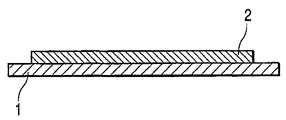
도1은 포지티브형 레지스트 층이 기판 상에 형성되는 상태를 도시하는 개략 단면도이다.1 is a schematic cross-sectional view showing a state in which a positive resist layer is formed on a substrate.
도2는 잉크 유로의 구조가 포지티브형 레지스트 층 내에 형성되는 상태를 도시하는 개략 단면도이다.Fig. 2 is a schematic cross sectional view showing a state in which the structure of the ink flow path is formed in the positive resist layer.
도3은 네거티브형 레지스트 층 및 잉크-반발 층이 형성되는 상태를 도시하는 개략 단면도이다.3 is a schematic cross-sectional view showing a state in which a negative resist layer and an ink-repellent layer are formed.
도4는 잉크 토출구가 형성되는 상태를 도시하는 개략 단면도이다.4 is a schematic sectional view showing a state in which an ink discharge port is formed.
도5는 보호 층 및 식각 마스크가 형성되는 상태를 도시하는 개략 단면도이다.5 is a schematic cross-sectional view showing a state in which a protective layer and an etching mask are formed.
도6은 잉크 공급 포트가 형성되는 상태를 도시하는 개략 단면도이다.6 is a schematic cross-sectional view showing a state in which an ink supply port is formed.
도7은 잉크 유로가 형성되는 잉크 제트 헤드의 구조를 도시하는 개략 단면도 이다.7 is a schematic cross-sectional view showing the structure of an ink jet head in which an ink flow path is formed.
본 발명에서 사용되는 광분해성 포지티브형 레지스트는 아크릴 에스테르 또는 메타크릴 에스테르로서 얻어지는 단위가 주요 성분으로서 적어도 함유되며 아크릴산 또는 메타크릴산으로부터 얻어지는 단위가 추가로 함유되는 아크릴 공중합체 조성물이다. 일반식 (1)에 의해 표현된 단위가 바람직한 아크릴 에스테르 또는 메타크릴 에스테르 단위로서 예시될 수 있으며, 일반식 (2)에 의해 표현된 단위가 아크릴산 또는 메타크릴산으로서 예시될 수 있다.The photodegradable positive resist used in the present invention is an acrylic copolymer composition in which a unit obtained as an acrylic ester or a methacrylic ester is at least contained as a main component and further a unit obtained from acrylic acid or methacrylic acid is further contained. The unit represented by general formula (1) can be illustrated as a preferable acrylic ester or methacrylic ester unit, and the unit represented by general formula (2) can be illustrated as acrylic acid or methacrylic acid.
일반식 (1)General formula (1)

(여기에서 R1은 수소 그리고 탄소가 1개 내지 3개의 범위 내에 있는 알킬기이며, R2는 탄소가 1개 내지 3개의 범위 내에 있는 알킬기이며, m은 양의 정수이다.)(Wherein R1 is hydrogen and an alkyl group having 1 to 3 carbons, R2 is an alkyl group having 1 to 3 carbons, and m is a positive integer.)
일반식 (2)General formula (2)

(여기에서 R3은 수소 그리고 탄소가 1개 내지 3개의 범위 내에 있는 알킬기 이며, n은 양의 정수이다.)(Wherein R3 is hydrogen and an alkyl group in which carbon is in the range of 1 to 3, n is a positive integer)
적어도, 일반식 (1)의 단위가 아크릴 에스테르 또는 메타크릴 에스테르로부터 얻어진 단위로서 예시될 수 있으며, 일반식 (2)의 단위가 아크릴산 또는 메타크릴산으로부터 얻어진 단위로서 예시될 수 있다.At least, the unit of general formula (1) can be illustrated as a unit obtained from an acrylic ester or methacrylic ester, and the unit of general formula (2) can be illustrated as a unit obtained from acrylic acid or methacrylic acid.
이제 도면을 참조하여, 본 발명이 각각의 공정에서 상세하게 기술될 것이다. 도1 내지 도7은 본 발명의 잉크 제트 헤드를 제조하는 방법을 개략적으로 도시하고 있다.Referring now to the drawings, the present invention will be described in detail in each process. 1 to 7 schematically show a method of manufacturing the ink jet head of the present invention.
공정 1: 포지티브형 레지스트 층 형성Process 1: Forming Positive Resist Layer
본 발명에서, 우선, 광분해성 포지티브형 레지스트 층(2)이 에너지 발생 소자를 갖는 기판 상에 형성된다(도1). 기판(1)은 잉크를 토출하는 에너지 발생 소자(도시되지 않음)를 포함한다. 유리, 세라믹, 금속 등의 재료로 제조된 기판이 본 발명에서 사용되는 기판(1)으로서 사용된다. 전열 발생 소자(electrothermal generating element) 또는 압전 소자(piezoelectric element)가 에너지 발생 소자로서 사용된다. 그러나, 에너지 발생 소자는 이러한 소자들에 제한되지 않는다. 전열 발생 소자가 에너지 발생 소자로서 사용될 때, 보호 피막(도시되지 않음)이 버블링(bubbling) 동안의 충격 완화 또는 잉크로부터 손상 감소 등의 목적을 위해 형성되는 것이 가능하다.In the present invention, first, a photodegradable
광분해성 포지티브형 레지스트는 포지티브형 레지스트 층(2)을 형성하기 위해 기판(1)의 표면 상으로 도포된다. 도포 방법의 예는 스핀 코팅 방법(spin coating method), 직접 코팅 방법(direct coating method) 및 적층물 전사 방법(laminate transferring method)을 포함한다. 그러나, 도포 방법은 전술된 예에 제한되지 않는다. 290 ㎚의 근처에서 감광 파장 범위를 갖는 폴리메틸 이소프로페닐 케톤(PMIPK) 또는 폴리비닐 케톤 등의 레지스트 그리고 250 ㎚의 근처에서 감광 파장 범위를 갖는 폴리메틸 메타크릴레이트(PMMA) 등의 메타크릴레이트 에스테르 단위를 함유하는 고분자 화합물로 제조되는 레지스트가 일반적으로 광분해성 포지티브형 레지스트로서 사용된다. 이들 레지스트에서, 광조사(photoirradiation)에 의한 분자량의 감소가 이용되며, 분자량이 감소되는 일부분만을 현상 용액 내로 용해시키기 위해 기본 수지가 용해되지 않는 현상 용액이 사용되며, 그에 의해 포지티브형 화상이 형성된다. 본 발명에서 사용되는 아크릴 공중합체는 또한 광조사에 의한 분자량의 감소의 진행을 이용함으로써 포지티브형 화상을 형성하며, 종래 기술의 문제점은 아크릴 공중합체의 수지 극성에 관심을 집중함으로써 해결된다.The photodegradable positive resist is applied onto the surface of the
현상 동안에 크랙의 발생을 방지하기 위해, 본 발명은 상세하게 후술될 기본 성분을 함유하는 현상 용액을 사용하는 것을 특징으로 한다. 그러나, 후술될 기본 성분을 함유하는 현상 용액이 사용될 때, 전술된 바와 같이 바람직하지 않은데, 이것은 감도 및 분리도의 감소가 분자 사이에서-교차 결합된 아크릴 공중합체 내에서 일어나기 때문이다. 그러므로, 본 발명에서 사용되는 아크릴 공중합체는 분자들 사이의 교차 결합이 분자량 및 조성을 최적화하기 위해 가능하면 크게 억제되도록 크랙이 현상 동안에 거의 발생되지 않는 고감도 레지스트가 형성되는 것을 특징으로 한다.In order to prevent the occurrence of cracks during development, the present invention is characterized by using a developing solution containing a basic component which will be described later in detail. However, when a developing solution containing the basic component described below is used, it is not preferable as described above, since a decrease in sensitivity and separation occurs in an inter-molecule-cross-linked acrylic copolymer. Therefore, the acrylic copolymer used in the present invention is characterized in that a highly sensitive resist is formed in which cracks hardly occur during development so that crosslinking between molecules is suppressed as large as possible to optimize molecular weight and composition.
나아가, 본 발명에서 사용되는 아크릴 공중합체에서, 극성은 구조 내에 포함된 아크릴산 또는 메타크릴산 성분의 함량에 의해 크게 변화된다. 즉, 아크릴 공중합체의 극성은 "공중합체 내에 포함된 아크릴산 또는 메타크릴산 성분의 비율" 그리고 "열 처리[프리-베이킹(pre-baking)]에 의한 분자들 사이의 교차 결합의 정도"에 크게 의존한다. 구조 내에 아크릴산 또는 메타크릴산을 함유하는 아크릴 공중합체에서, 카르복실산의 탈수 및 응결(dehydration and condensation)이 고온에서의 처리에 의해 분자들 사이의 교차 결합을 발생시키기 위해 진행되며, 그 결과 아크릴산 또는 메타크릴산을 함유하는 아크릴 공중합체는 용매-저항성을 개선시키는 데 있어서 효과적이다. 그러나, 극성은 또한 후술될 포지티브형 레지스트에 코팅되는 네거티브형 레지스트에 대한 용해도(solubility)에 크게 영향을 주기 때문에, 극성은 분자들 사이의 교차 결합에 의해 감소된다. 결과적으로, 종종 용매-저항성은 감소된다.Furthermore, in the acrylic copolymer used in the present invention, the polarity is greatly changed by the content of the acrylic acid or methacrylic acid component included in the structure. That is, the polarity of the acrylic copolymer is largely dependent on "the ratio of acrylic or methacrylic acid components contained in the copolymer" and "the degree of crosslinking between molecules by heat treatment (pre-baking)". Depends. In acrylic copolymers containing acrylic acid or methacrylic acid in the structure, dehydration and condensation of the carboxylic acid proceeds to generate crosslinks between the molecules by treatment at high temperature, resulting in acrylic acid Or acrylic copolymers containing methacrylic acid are effective in improving solvent-resistance. However, since the polarity also greatly affects the solubility of the negative resist coated on the positive resist, which will be described later, the polarity is reduced by crosslinking between the molecules. As a result, solvent-resistance is often reduced.
이들 관점에 비추어, 본 발명에서, 아크릴 공중합체는 극성[아크릴산 또는 메타크릴산 성분의 양]을 조정하기 위해 "아크릴산 또는 메타크릴산의 비율" 그리고 "열 처리에 의한 분자들 사이의 교차 결합의 정도"를 제어함으로써 최적의 상태에서 포지티브형 레지스트로서 사용된다.In view of these aspects, in the present invention, the acrylic copolymer is used in order to adjust the polarity (amount of acrylic acid or methacrylic acid component) of "a ratio of acrylic acid or methacrylic acid" and "crosslinking between molecules by heat treatment. By controlling the degree "to be used as a positive resist in an optimal state.
진지한 연구의 결과로서, 본 발명자들은 일반식 (1)에 의해 표현된 아크릴 에스테르 또는 메타크릴 에스테르가 주요 성분으로 함유되며 일반식 (2)에 의해 표현된 5 내지 30 중량%의 아크릴산 또는 메타크릴산이 함유되며 중량 평균 분자량(폴리스티렌의 변환체)이 50000 내지 300000의 범위 내에 있는 아크릴 공중합체가 특히 바람직하게 사용된다는 것을 밝혀냈다.As a result of serious research, the inventors have found that 5 to 30% by weight of acrylic acid or methacrylic acid represented by the general formula (2) contains the acrylic ester or methacrylic ester represented by the general formula (1) as main components. It has been found that acrylic copolymers which are contained and whose weight average molecular weight (conversion of polystyrene) is in the range of 50000 to 300000 are particularly preferably used.
예컨대, 본 발명에서 사용되는 아크릴 에스테르 또는 메타크릴 에스테르는 다음의 식 (3) 및 식 (4)에 기재된 단량체를 사용하여 라디칼 공중합으로부터 형성될 수 있다.For example, the acrylic ester or methacryl ester used in the present invention can be formed from radical copolymerization using the monomers described in the following formulas (3) and (4).
식 (3)Equation (3)

(여기에서 R1은 수소 그리고 탄소가 1개 내지 3개의 범위 내에 있는 알킬기이며, R2는 탄소가 1개 내지 3개의 범위 내에 있는 알킬기이다.)(Wherein R1 is hydrogen and an alkyl group having 1 to 3 carbons and R2 is an alkyl group having 1 to 3 carbons.)
식 (4)Equation (4)

(여기에서 R3은 수소 그리고 탄소가 1개 내지 3개의 범위 내에 있는 알킬기이다.)Where
"크랙-저항성(crack-resistance property)", "현상 용액 내로의 용해도(감도)" 그리고 "코팅 레지스트-저항성(분리도)"이 잉크 제트 헤드로서 사용되는 잉크 유로를 형성하는 포지티브형 레지스트의 중요한 인자로서 예시될 수 있으며, 각각의 특성에서 효과적인 조건이 바람직해진다. 후술될 현상 용액의 종류, 분자들 사이의 교차 결합의 정도 그리고 후술될 네거티브형 레지스트의 도포 용매는 본 발명에 따른 아크릴 공중합체의 "크랙-저항성"에 크게 영향을 준다. 구체적으로, 후술 될 염기성 극성 현상 용액의 사용은 크랙을 감소시키는 데 있어서 큰 효과를 갖는다. 그러므로, 크랙은 메틸 이소부틸 케톤 및 크실렌 등의 비극성 현상 용액에 비해 본 발명의 포지티브형 레지스트를 현상하는 동안에 거의 발생되지 않는다. 분자들 사이의 교차 결합이 진행됨에 따라, 응력이 경화 수축에 의해 공중합체 내에서 발생된다. 그러므로, 교차 결합이 어떤 정도까지 진행되는 공중합체에서, 종종 크랙은 사후-프리베이킹 냉각(post-prebaking cooling)과 관련된 수축에 의해 또는 현상 동안의 급속한 팽창에 의해 발생된다. 마찬가지로, 이러한 현상은 후술될 포지티브형 레지스트에 코팅되는 네거티브형 레지스트의 도포 용매에 의해 일어나기 쉬우며, 크랙이 발생되지 않는 용매가 네거티브형 레지스트의 도포 용매로서 선택될 것이 필요하다.The "crack-resistance property", "solubility into the developing solution (sensitivity)" and "coating resist-resistance (separation)" are important for positive resists forming ink flow paths used as ink jet heads. It may be exemplified as a factor, and conditions effective in each characteristic are preferred. The type of developing solution to be described later, the degree of crosslinking between the molecules and the application solvent of the negative type resist to be described later greatly influence the "crack-resistance" of the acrylic copolymer according to the present invention. Specifically, the use of the basic polar developing solution described later has a great effect in reducing cracks. Therefore, cracks hardly occur during the development of the positive resist of the present invention as compared to nonpolar developing solutions such as methyl isobutyl ketone and xylene. As crosslinking between molecules progresses, stress is generated in the copolymer by cure shrinkage. Therefore, in copolymers where crosslinking proceeds to some extent, cracks are often caused by shrinkage associated with post-prebaking cooling or by rapid expansion during development. Similarly, this phenomenon is likely to occur by the application solvent of the negative resist coated on the positive resist described later, and it is necessary that a solvent which does not generate cracks be selected as the application solvent of the negative resist.
본 발명에 따른 아크릴 공중합체에서, 포지티브형 레지스트 및 현상 용액의 극성들 사이의 관계가 "현상 용액 내로의 용해도(감도)"에 크게 영향을 준다. 구체적으로, 극성 현상 용액이 높은 극성을 갖는 포지티브형 레지스트에 대해 사용될 때, 용해도는 개선된다. 그러나, 아크릴산 또는 메타크릴산 성분의 비율이 과도하게 높을 때, 극성은 수지로서 과도하게 증가되기 때문에, 피막의 감소가 현상 동안에 비노광 부분에서 현저해지며, 점도가 중합 동안에 증가되며, 이것은 합성이 거의 수행되지 않게 한다. 그러므로, 과도하게 높은 비율의 아크릴산 또는 메타크릴산 성분을 갖는 극성 현상 용액은 포지티브형 레지스트에 적절하지 않다. 후술될 염기성 극성 현상 용액이 본 발명에서 사용될 때, 아크릴산 또는 메타크릴산 성분의 비율은 5% 내지 30%의 범위 내에 있으며, 염기성 극성 현상 용액은 바람직하게는 분자들 사이의 교차 결합의 진행이 가능하면 크게 억제되는 조건에서 사용된다. 용해도는 분자량이 작을 때 비노광 부분에서 증가되며, 감도는 분자량이 클 때 저하된다. 그러므로, 포지티브형 레지스트는 분자량이 50000 내지 300000의 범위 내에 있을 때 사용되는 것이 바람직하다. 나아가, 분자들 사이의 교차 결합이 억제될 때, 열 처리가 장시간 동안 고온에서 요구되지 않으며, 그 결과 주기가 바람직하게 개선된다.In the acrylic copolymer according to the present invention, the relationship between the polarities of the positive resist and the developing solution greatly influences the "solubility (sensitivity) into the developing solution". Specifically, when the polarity developing solution is used for positive type resist having high polarity, solubility is improved. However, when the proportion of the acrylic acid or methacrylic acid component is excessively high, since the polarity is excessively increased as the resin, the decrease in the film becomes noticeable in the non-exposed portion during development, and the viscosity is increased during the polymerization, which causes the synthesis to Rarely performed. Therefore, polar developing solutions with excessively high proportions of acrylic or methacrylic acid components are not suitable for positive resists. When the basic polar developing solution described below is used in the present invention, the proportion of the acrylic acid or methacrylic acid component is in the range of 5% to 30%, and the basic polar developing solution is preferably capable of crosslinking between molecules. It is used under conditions that are greatly suppressed. Solubility is increased in the unexposed portions when the molecular weight is small, sensitivity is lowered when the molecular weight is large. Therefore, the positive resist is preferably used when the molecular weight is in the range of 50000 to 300000. Furthermore, when crosslinking between molecules is suppressed, heat treatment is not required at high temperatures for a long time, and as a result the cycle is preferably improved.
비극성 현상 용액의 사용에 대해, 포지티브형 레지스트의 낮은 극성 또는 분자들 사이의 교차 결합의 진행의 조건인 5% 미만의 비율의 아크릴산 또는 메타크릴산은 용해도를 개선시킨다. 그러나, 후술될 코팅 레지스트-저항성 및 크랙-저항성은 서로 양립할 수 없기 때문에, 잉크 유로에 대한 포지티브형 레지스트에 적절하지 않다.For the use of nonpolar developing solutions, less than 5% of acrylic acid or methacrylic acid, which is a condition of the low polarity of the positive resist or the progress of crosslinking between molecules, improves solubility. However, the coating resist-resistance and crack-resistance to be described later are not compatible with each other, and therefore are not suitable for the positive resist for the ink flow path.
포지티브형 레지스트의 극성과 네거티브형 레지스트의 도포 용매의 극성 사이의 관계는 본 발명에 따른 아크릴 공중합체의 "코팅 레지스트-저항성(분리도)"에 크게 영향을 준다. 구체적으로, 포지티브형 레지스트의 용해 및 변형은 높은 극성을 갖는 포지티브형 레지스트에 낮은 극성을 갖는 네거티브형 레지스트를 코팅함으로써 목표 분리도를 갖는 잉크 유로를 형성하기 위해 억제될 수 있다. 포지티브형 레지스트를 용해 및 변형시키기 위해, 50000 이상의 분자량을 갖는 포지티브형 레지스트를 사용하는 것이 바람직하다. 코팅에 적절한 네거티브형 레지스트가 상세하게 후술될 것이다.The relationship between the polarity of the positive type resist and the polarity of the application solvent of the negative type resist greatly influences the "coating resist-resistance (separation degree)" of the acrylic copolymer according to the present invention. Specifically, dissolution and deformation of the positive resist can be suppressed to form an ink flow path having a target separation degree by coating a negative polarity having a low polarity on a positive polarity having a high polarity. In order to dissolve and modify the positive resist, it is preferable to use a positive resist having a molecular weight of 50000 or more. Negative resists suitable for coating will be described later in detail.
공정 2: 잉크 유로 패턴 형성Process 2: ink flow path pattern formation
포지티브형 레지스트 층(2)이 형성된 후, 포지티브형 레지스트 층(2)의 소정의 영역이 노광 공정 및 현상 공정을 포함하는 사진 공정을 통해 제거되며, 잉크 유로 패턴이 형성된다(도2). 우선, 포지티브형 레지스트 층(2)에는 잉크 유로 패턴이 그려져 있는 석영 마스크를 통해 이온화 방사선이 조사된다. 이러한 시점에서, 본 발명에서 사용되는 광분해성 포지티브형 레지스트의 감광 파장 범위로 되어 있는 250 ㎚의 근처에서의 파장 범위를 포함하는 이온화 방사선이 이온화 방사선으로서 사용된다. 그러므로, 포지티브형 레지스트 층(2)에서, 이온화 방사선이 조사되는 영역 내에서 주 사슬 분해 반응(chain degradation reaction)이 발생되며, 현상 용액에 대한 영역의 용해도가 선택적으로 개선된다. 따라서, 잉크 유로가 되는 구조가 포지티브형 레지스트 층(2)을 현상함으로써 형성될 수 있다.After the positive resist
현상 용액에 대해, 용해도가 개선되는 노광 부분을 용해시키지 않고 또한 비노광 부분을 용해시키지 않기만 하면 임의의 용매가 적용 가능하다. 그러나, 본 발명에서, 크랙이 현상 동안에 방지된다. 나아가, 전술된 바와 같이, 본 발명은 높은 감도 및 높은 분리도를 성취하기 위해 분자량의 크기 그리고 또한 수지의 극성에 대해 관심을 집중한다. 그러므로, 염기성 현상 용액을 사용하는 것이 바람직하다. 진지한 연구의 결과로서, 본 발명자들은 (1) 6개 이상의 탄소를 갖고, 임의의 비율로 물과 혼합될 수 있는 글리콜 에테르, (2) 함질소 염기성 유기 용매, 그리고 (3) 물을 함유하는 현상 용액이 바람직하게 사용된다는 것을 밝혀냈다. 예컨대, 일본 특허 공개 제H03-010089호는 X-선 사진 공정에서 레지스트로서 사용되는 PMMA 현상 용액을 개시하고 있으며, 일본 특허 공개 제H03-010089호에 개시된 조성을 갖는 현상 용액이 또한 본 발명에서 바람직하게 사용되는 것이 가능하다. 각각의 조성은 임의적으로 선택될 수 있다. 특히, (1)이 50% 내지 70%의 범위 내에 있 으며 (2)가 20% 내지 30%의 범위 내에 있으며 (3)이 잔량인 현상 용액을 사용하는 것이 바람직하다.For the developing solution, any solvent can be applied as long as it does not dissolve the exposed portion whose solubility is improved and does not dissolve the non-exposed portion. However, in the present invention, cracks are prevented during development. Furthermore, as mentioned above, the present invention focuses attention on the size of the molecular weight and also the polarity of the resin in order to achieve high sensitivity and high degree of separation. Therefore, it is preferable to use a basic developing solution. As a result of serious research, the inventors have found (1) glycol ethers having at least 6 carbons, which can be mixed with water in any proportion, (2) nitrogen-containing basic organic solvents, and (3) water It was found that the solution is preferably used. For example, Japanese Patent Laid-Open No. H03-010089 discloses a PMMA developing solution used as a resist in an X-ray photographic process, and a developing solution having a composition disclosed in Japanese Patent Laid-Open No. H03-010089 is also preferably used in the present invention. It is possible to be used. Each composition can be chosen arbitrarily. In particular, it is preferable to use a developing solution in which (1) is in the range of 50% to 70%, (2) is in the range of 20% to 30%, and (3) is the balance.
공정 3: 네거티브형 레지스트 층 형성Step 3: Form Negative Resist Layer
그 다음에, 잉크 유로 패턴을 형성하는 포지티브형 레지스트에는 잉크 유로 벽을 형성하는 네거티브형 레지스트 층(3)이 코팅된다(도3). 양이온 중합(cationic polymerization) 및 라디칼 중합(radical polymerization) 등의 반응이 이용되는 재료가 네거티브형 레지스트로서 사용될 수 있다. 그러나, 네거티브형 레지스트는 전술된 재료에 제한되지 않는다. 양이온 중합 반응이 이용되는 네거티브형 레지스트를 예시하면, 중합 또는 교차 결합은 네거티브형 레지스트 내에 포함되고 네거티브형 레지스트 내에 포함되는 광-양이온 중합 개시제로부터 발생되는 양이온에 의해 양이온 중합을 수행할 수 있는 단량체 또는 중합체 분자들 사이에서 진행된다. 방향족 아이오도늄 염, 방향족 설포늄 염 등이 광-양이온 중합 개시제로서 예시될 수 있다. 구체적으로, 아사히 덴까 컴퍼니, 리미티드로부터 이용 가능한 SP-170 및 SP-150(제품명)이 예시될 수 있다.Then, the negative resist forming the ink flow path pattern is coated with the negative resist
에폭시기, 비닐 에테르기 또는 옥세탄기를 갖는 단량체 또는 중합체가 양이온 중합이 수행될 수 있는 단량체 또는 중합체에 적절하다. 그러나, 단량체 또는 중합체는 에폭시기, 비닐 에테르기 또는 옥세탄기를 갖는 단량체 또는 중합체에 제한되지 않는다. 비스페놀 A형 에폭시 수지, 노볼락형 에폭시 수지, 아론 옥세탄 OXT-211(도아고세이 컴퍼니, 리미티드의 제품명) 및 셀록사이드 2021(다이셀 케미컬 인더스트리즈, 리미티드의 제품명) 등의 고리 지방족(Cycloaliphatic) 에폭시 수지 그리고 AOE(다이셀 케미컬 인더스트리즈, 리미티드의 제품명) 등의 곧은-사슬 알킬기를 갖는 모노에폭사이드가 예로서 예시될 수 있다. 나아가, 일본 특허 제3,143,308호에 기재된 다관능기(polyfunctional) 에폭시 수지 예컨대 EHPE-3150(다이셀 케미컬 인더스트리즈, 리미티드의 제품명) 등이 극히 높은 양이온 중합 성질을 나타내고, 경화에 의해 높은 교차 결합 밀도를 나타낸다. 그러므로, 우수한 강도를 갖는 경화 재료가 얻어지므로, EHPE-3150 등이 특히 바람직하다.Monomers or polymers having epoxy groups, vinyl ether groups or oxetane groups are suitable for monomers or polymers in which cationic polymerization can be carried out. However, the monomer or polymer is not limited to the monomer or polymer having an epoxy group, vinyl ether group or oxetane group. Cycloaliphatic epoxy such as bisphenol A type epoxy resin, novolac type epoxy resin, Aaron Oxetane OXT-211 (product name of Doagosei Co., Ltd.) and Celoxide 2021 (product name of Daicel Chemical Industries, Ltd.) Resin and monoepoxides having straight-chain alkyl groups such as AOE (diesel chemical industries, product name of LIMITED) can be exemplified by way of example. Furthermore, polyfunctional epoxy resins described in Japanese Patent No. 3,143,308 such as EHPE-3150 (product name of Daicel Chemical Industries, Limited) and the like exhibit extremely high cation polymerization properties and exhibit high crosslink density by curing. . Therefore, since a hardened material having excellent strength is obtained, EHPE-3150 and the like are particularly preferable.
본 발명에서, 네거티브형 레지스트는 포지티브형 레지스트에 의해 형성된 유로 패턴에 네거티브형 레지스트가 코팅된 상태에서 사용된다. 그러므로, 포지티브형 레지스트를 용해 및 변형시키지 않는 도포 용매를 선택할 것이 필요하다. 진지한 연구의 결과로서, 본 발명자들은 포지티브형 레지스트와 반대 극성을 갖는 메틸 이소부틸 케톤 또는 크실렌이 네거티브형 레지스트에서 사용되는 도포 용매로서 사용되는 것이 바람직하다는 것을 밝혀냈다.In the present invention, the negative resist is used in the state where the negative resist is coated on the flow path pattern formed by the positive resist. Therefore, it is necessary to select a coating solvent that does not dissolve and deform the positive resist. As a result of serious research, the inventors have found that methyl isobutyl ketone or xylene having a polarity opposite to that of the positive type resist is preferably used as the coating solvent used in the negative type resist.
도포 피막을 형성하는 데 있어서 피막 평탄도 등의 도포 성질을 개선시키기 위해, 글리콜 화합물이 네거티브형 레지스트 내에 포함되는 것이 또한 바람직하다. 디에틸렌 글리콜 디메틸 에테르 및 트리에틸렌 글리콜 메틸 에테르 등의 화합물이 예로서 예시될 수 있다. 그러나, 글리콜 화합물은 전술된 화합물에 제한되지 않는다.In order to improve coating properties such as coating flatness in forming the coating film, it is also preferable that a glycol compound is included in the negative type resist. Compounds such as diethylene glycol dimethyl ether and triethylene glycol methyl ether can be exemplified by way of example. However, the glycol compound is not limited to the compound described above.
네거티브형 레지스트 층(3)이 스핀 코팅 방법 및 직접 코팅 방법 등의 방법에 의해 잉크 유로가 되는 구조 상으로 네거티브형 레지스트를 도포함으로써 형성된다.The negative resist
그 다음에, 잉크-반발 층(4)이 필요에 따라 네거티브형 레지스트 층(3) 상에 형성된다. 이러한 경우에, 네거티브형 레지스트와 같이, 잉크-반발 층(4)은 분자들 사이의 교차 결합이 수행될 수 있는 감광성을 갖는 것이 바람직하다. 잉크-반발 층(4) 및 네거티브형 레지스트는 서로와 구획화되지 않을 것이 또한 필요하다. 잉크-반발 층(4)은 스핀 코팅 방법, 직접 코팅 방법 및 적층물 전사 방법 등의 방법에 의해 형성될 수 있다.Then, an ink-
공정 4: 잉크 토출구 형성Step 4: forming the ink discharge port
그 다음에, 잉크 토출구가 네거티브형 레지스트 층 내의 소정의 부분 내에 형성된다(도4). 공정 4에서, 잉크 토출구가 되는 부분은 광으로부터 차단되며, 다른 부분에는 광이 조사되며, 이것은 네거티브형 레지스트가 경화되게 한다. 이러한 시점에서, 잉크-반발 층(4)의 수지가 또한 동시에 경화되며, 그 다음에 현상이 잉크 토출구(7)에 수행된다. 네거티브형 레지스트 층(3) 및 잉크-반발 층(4)에 대한 현상 용액으로서, 노광 부분이 용해되지 않으며 비노광 부분이 완전히 제거될 수 있으며 비노광 부분의 아래에 배열된 광분해성 포지티브형 레지스트가 용해되지 않는 현상 용액이 최적이다. 메틸 이소부틸 케톤, 크실렌 또는 메틸 이소부틸 케톤/크실렌의 혼합 용매가 사용될 수 있다. 복수개의 헤드가 일반적으로 1개의 기판 상에 배열되고 절단 공정을 통해 잉크 제트 헤드로서 사용되기 때문에, 잉크 유로 패턴을 형성하는 포지티브형 레지스트는 절단 동안의 먼지 대책으로서 절단 공정 후 용해 및 제거된다. 이것은 광분해성 포지티브형 레지스트가 용해되지 않는 것이 중요하기 때문이다.Then, an ink ejection opening is formed in a predetermined portion in the negative resist layer (Fig. 4). In
공정 5: 잉크 공급 포트 및 잉크 유로 형성Process 5: ink supply port and ink flow path formation
그 다음에, 기판(1)을 관통하는 잉크 공급 포트(8)가 형성된다(도5 및 도6). 이방성 식각 또는 건식각이 대개 잉크 공급 포트(8)를 형성하는 방법으로서 사용되지만, 이 방법은 이방성 식각 또는 건식각에 제한되지 않는다. 특정한 결정 배향을 갖는 Si 기판이 사용되는 이방성 식각 방법이 예로서 설명될 것이다. 우선, 식각 마스크(6)(예컨대, 히따찌 케미컬 컴퍼니, 리미티드에 의해 제조되는 히말)가 잉크 공급 포트의 크기를 갖는 슬릿 부분만이 남겨진 상태에서 기판(1)의 후방측 내에 형성된다(도5). 그 다음에, 식각 마스크(6)가 식각 용액 내로 따뜻한 상태로 담가진다. 식각 용액은 포타슘 수산화물, 소듐 수산화물, 테트라메틸 암모늄 수산화물 등의 수용액을 포함하는 알칼리 식각 용액으로 되어 있다. 그러므로, 기판 내의 슬릿 부분으로부터 노출된 부분만이 이방성으로써 용해될 수 있으며, 잉크 공급 포트(8)가 형성될 수 있다(도6 참조). 그 다음에, 식각 마스크(6)가 필요에 따라 제거된다. 이러한 시점에서, 식각 용액으로부터 기판의 표면 상의 네거티브형 레지스트 층(3) 및 잉크-반발 층(4)을 보호하기 위해, 식각 용액-저항성을 갖는 수지(예컨대, 도꾜 오오까 고교 컴퍼니, 리미티드에 의해 제조되는 OBC)가 보호 층(5)으로서 기판 표면 상에 형성되는 것이 또한 가능하다.Then, an
그 다음에, 잉크 유로 패턴을 형성하는 포지티브형 레지스트가 잉크 토출구와 연통되는 잉크 유로를 형성하기 위해 제거된다(도7 참조). 이러한 공정에서, 잉크 유로 패턴을 형성하는 포지티브형 레지스트에는 포지티브형 레지스트의 분해 반응을 발생시키기 위해 이온화 방사선이 조사되며, 이것은 제거 용액에 대한 용해 도를 개선시킨다. 포지티브형 레지스트 층(2)의 패터닝을 위한 것과 동일한 이온화 방사선이 사용될 수 있다. 그러나, 공정의 목적은 잉크 유로가 되는 구조를 제거함으로써 잉크 유로를 형성하는 것이기 때문에, 이온화 방사선의 조사가 마스크 없이 표면의 위에서 수행될 수 있다. 그 다음에, 잉크 유로 패턴을 형성하는 포지티브형 레지스트가 포지티브형 레지스트 층(2)의 패터닝을 위한 것과 동일한 현상 용액으로써 완전히 제거되는 것이 가능하다. 그러나, 이러한 공정에서, 포지티브형 레지스트는 패터닝 성질을 고려하지 않고 용해될 수 있으며, 네거티브형 레지스트 층 및 잉크-반발 층에 영향을 주지 않는 용매가 사용될 수 있다. 잉크 제트 헤드가 전술된 공정에서 제조될 수 있다.Then, the positive resist forming the ink flow path pattern is removed to form an ink flow path in communication with the ink discharge port (see Fig. 7). In this process, the positive resist that forms the ink flow path pattern is irradiated with ionizing radiation to generate a decomposition reaction of the positive resist, which improves solubility in the removal solution. The same ionizing radiation can be used as for the patterning of the positive resist
본 발명에서 설명된 아크릴 공중합체를 사용하여 잉크 제트 헤드를 제조하는 방법에서, 재료가 토출구 형성 영역 내에서 사용되기만 하면 임의의 잉크 제트 헤드 제조 방법이 모드와 관계 없이 본 발명 내에 포함된다.In the method for producing an ink jet head using the acrylic copolymer described in the present invention, any method of manufacturing an ink jet head is included in the present invention regardless of the mode as long as the material is used in the discharge port forming region.
본 발명이 예에 의해 더욱 상세하게 후술될 것이다.The invention will be described in more detail below by way of example.
(예 1)(Example 1)
예 1에서, 잉크 제트 헤드는 도1 내지 도7에 도시된 잉크 제트 헤드를 제조하는 방법에 의해 제조된다. 우선, 잉크를 토출하는 에너지 발생 소자가 형성되고 구동기 및 논리 회로가 형성되는 실리콘 기판(1)이 준비된다. 그 다음에, 광분해성 포지티브형 레지스트를 포함하는 포지티브형 레지스트 층(2)이 기판(1) 상에 형성된다(도1). 광분해성 포지티브형 레지스트와 관련하여, 후술될 수지가 25 중량%의 고체 함량 농도에서 디에틸렌 글리콜 디메틸 에테르 내에 용해되는 레지스트 용 액이 스핀 코팅 방법에 의해 도포된다:In Example 1, the ink jet head is manufactured by the method of manufacturing the ink jet head shown in Figs. First, a
* 메타크릴산 메틸(MMA)/메타크릴산(MAA) 공중합체,* Methyl methacrylate (MMA) / methacrylic acid (MAA) copolymer,
* MMA/MAA = 90/10(중량비), 그리고MMA / MAA = 90/10 (weight ratio), and
* 중량 평균 분자량 = 170000(폴리스티렌의 변환체).* Weight average molecular weight = 170000 (conversion of polystyrene).
도포된 레지스트 용액이 3분 동안 100℃의 온도에서 핫 플레이트(hot plate) 상에서 프리-베이킹되며, 프리-베이킹이 14 ㎛의 피막 두께를 갖는 포지티브형 레지스트 층(2)을 형성하기 위해 1시간 동안 150℃의 온도에서 질소로-대체된 오븐(nitrogen-replaced oven) 내에서 추가로 수행된다(도1). 카르복실기가 IR로써 수지 내의 메타크릴산 내에 포함되는 카르복실기로부터 유도되는 히드록실기의 양으로부터 식별될 때, 분자들 사이의 교차 결합을 위해 사용된 카르복실기는 20% 이하이다.The applied resist solution is pre-baked on a hot plate at a temperature of 100 ° C. for 3 minutes, and the pre-baking is carried out for 1 hour to form a positive resist
그 다음에, 포지티브형 레지스트 층(2)에는 딥(deep)-UV 노광 장치 UX-3000(우시오 인코포레이티드의 제품명)을 사용하여 유로 패턴이 그려져 있는 마스크를 통해 50000 mJ/㎠의 노광에서 딥-UV 광이 조사된다. 그 다음에, 포지티브형 레지스트 층(2)이 다음의 성분을 갖는 혼합 용액으로써 현상된다:The positive resist
* 디에틸렌 글리콜 모노부틸 에테르: 60 체적%,* Diethylene glycol monobutyl ether: 60% by volume,
* 모노에탄올아민: 5 체적%,Monoethanolamine: 5% by volume,
* 모르폴린: 20 체적%, 그리고* Morpholine: 20% by volume, and
* 이온-교환수: 15 체적%.Ion-exchanged water: 15% by volume.
그 다음에, 잉크 유로 패턴이 이소프로필 알코올로써 린스 처리(rinsing treatment)를 수행함으로써 형성된다(도2).Then, an ink flow path pattern is formed by performing a rinsing treatment with isopropyl alcohol (Fig. 2).
그 다음에, 잉크 유로 패턴에는 네거티브형 레지스트가 코팅된다(도3). 다음의 조성을 갖는 레지스트 용액이 네거티브형 레지스트로서 사용된다:Then, a negative resist is coated on the ink flow path pattern (Fig. 3). A resist solution having the following composition is used as a negative resist:
* 에폭시 수지: EHPE-3150(다이셀 케미컬 인더스트리즈, 리미티드의 제품명): 100 중량부,* Epoxy resin: EHPE-3150 (product name of Daicel Chemical Industries, Limited): 100 parts by weight,
* 실란 결합제(coupling agent): A-187(니뽄 유니카 컴퍼니 리미티드의 제품명): 5 중량부,* Silane Coupling Agent: A-187 (Product Name of Nippon Unica Company Limited): 5 parts by weight,
* 광중합 개시제(photopolymerization initiator): SP170(아사히 덴까 컴퍼니, 리미티드의 제품명): 2 중량부,* Photopolymerization initiator: SP170 (product name of Asahi Denka Co., Ltd.): 2 parts by weight,
* 첨가제: HFAB(센트럴 글래스 컴퍼니, 리미티드의 제품명): 20 중량부, 그리고* Additive: HFAB (Central Glass Company, Limited's product name): 20 parts by weight, and
* 용매: 크실렌: 80 중량부.Solvent: xylene: 80 parts by weight.
네거티브형 레지스트가 스핀 코팅 방법에 의해 도포되며, 프리-베이킹이 (평판 상에) 20 ㎛의 두께를 갖는 네거티브형 레지스트 층(3)을 형성하기 위해 3분 동안 90℃에서 핫 플레이트 상에서 수행된다. 다음의 조성을 갖는 수지로 제조된 감광 잉크-반발 층(3)이 적층 방법에 의해 네거티브형 레지스트 층(3) 상에 형성된다:The negative resist is applied by a spin coating method and pre-baking is performed on a hot plate at 90 ° C. for 3 minutes to form a negative resist
* 에폭시 수지: EHPE-3150(다이셀 케미컬 인더스트리즈, 리미티드의 제품명): 35 중량부,Epoxy resin: EHPE-3150 (product name of Daicel Chemical Industries, Limited): 35 parts by weight,
* 2,2-비스(4-글리시딜 옥시페닐)헥사플루오로프로판: 25 중량부,* 2,2-bis (4-glycidyl oxyphenyl) hexafluoropropane: 25 parts by weight,
* 1,4-비스(2-히드록시헥사플루오로이소프로필)벤젠: 25 중량부,* 1,4-bis (2-hydroxyhexafluoroisopropyl) benzene: 25 parts by weight,
* 3-(2-퍼플루오로헥실)에톡시-1,2-에폭시프로판: 16 중량부,* 3- (2-perfluorohexyl) ethoxy-1,2-epoxypropane: 16 parts by weight,
* 실란 결합제: A-187(니뽄 유니카 컴퍼니 리미티드의 제품명): 4 중량부,* Silane binder: A-187 (product name of Nippon Unica Company Limited): 4 parts by weight,
* 광중합 개시제: SP170(아사히 덴까 컴퍼니, 리미티드의 제품명): 1.5 중량부, 그리고* Photopolymerization initiator: SP170 (product name of Asahi Denka Company, Limited): 1.5 parts by weight, and
* 디에틸렌 글리콜 모노에틸 에테르: 200 중량부.Diethylene glycol monoethyl ether: 200 parts by weight.
그 다음에, 패턴 노광이 마스크 정렬기(mask aligner) MPA600FA(캐논 인코포레이티드의 제품명)를 사용하여 잉크 토출구 패턴이 그려져 있는 마스크를 통해 300 mJ/㎠의 노광에서 수행된다.Then, pattern exposure is performed at an exposure of 300 mJ /
그 다음에, PEB가 180초 동안 90℃에서 수행되며, 현상이 메틸 이소부틸 케톤/크실렌 = 2/3의 용액으로써 수행되며, 린스 처리가 크실렌으로써 수행되며, 그에 의해 잉크 토출구(7)를 형성한다(도4).Then, PEB is carried out at 90 ° C. for 180 seconds, development is carried out with a solution of methyl isobutyl ketone / xylene = 2/3, and a rinse treatment is carried out with xylene, thereby forming an ink discharge opening 7 (Fig. 4).
그 다음에, 잉크 공급 포트(8)가 식각 처리에 의해 기판(1)의 후방측 상에 형성된다. OBC(도꾜 오오까 고교 컴퍼니, 리미티드의 제품명)가 잉크-반발 층(4)의 표면의 위에서 보호 층(5)으로서 도포된다. 그 다음에, 슬릿형 식각 마스크(6)가 폴리에테르아미드 수지 히말(히따찌 케미컬 컴퍼니, 리미티드의 제품명)로써 기판의 후방측 상에 형성되며(도5), 이방성 식각이 80℃에서 테트라메틸 암모늄 수산화물 수용액 내로 식각 마스크(6)를 담금으로써 잉크 공급 포트(8)를 형성하기 위해 실리콘 기판에 수행된다(도6). 식각 마스크(6)는 기판이 준비될 때 미리 형성되는 것이 가능하다.Then, an
보호 층(5)으로 되어 있는 OBC(제품명)가 크실렌으로써 제거된 후, 잉크 유 로 패턴을 형성하는 포지티브형 레지스트는 딥-UV 노광 장치 UX-3000(우시오 인코포레이티드의 제품명)을 사용하여 잉크-반발 층(4)의 위로부터 70000 mJ/㎠의 노광에서 잉크 유로 패턴을 노광함으로써 용해도가 높아진다. 잉크 유로 패턴은 초음파가 가해지면서 메틸 락테이트 내로 잉크 유로 패턴을 담금으로써 제거되며, 도7에 도시된 잉크 제트 헤드가 형성된다.After the OBC (product name) serving as the
카르복실기가 IR로써 수지 내의 메타크릴산 내에 포함되는 카르복실기로부터 유도되는 히드록실기의 양으로부터 식별될 때, 분자들 사이의 교차 결합을 위해 사용된 카르복실기는 20% 이하이다.When the carboxyl group is identified from the amount of hydroxyl groups derived from the carboxyl groups included in methacrylic acid in the resin by IR, the carboxyl group used for crosslinking between the molecules is 20% or less.
전술된 방법에 의해 제조된 잉크 제트 헤드에서, 포지티브형 레지스트 층(2)의 크랙 그리고 용해 및 변형은 관찰되지 않는다.In the ink jet head produced by the method described above, no cracking and dissolution and deformation of the positive resist
전술된 방법에 의해 제조된 잉크 제트 헤드가 토출 및 기록 평가를 수행하기 위해 프린터 상에 장착될 때, 안정된 인쇄가 실현될 수 있으며, 고품질 인쇄 매체가 얻어진다.When the ink jet head manufactured by the above-described method is mounted on a printer to perform ejection and recording evaluation, stable printing can be realized, and a high quality print medium is obtained.
(예 2)(Example 2)
잉크 제트 헤드는 후술될 수지가 포지티브형 레지스트 층(2)으로서 사용된다는 점을 제외하면 예 1과 동일한 방식으로 제조된다:The ink jet head is manufactured in the same manner as in Example 1 except that the resin to be described later is used as the positive resist layer 2:
* 메타크릴산 메틸(MMA)/메타크릴산(MAA) 공중합체,* Methyl methacrylate (MMA) / methacrylic acid (MAA) copolymer,
* MMA/MAA = 90/10(중량비), 그리고MMA / MAA = 90/10 (weight ratio), and
* 중량 평균 분자량 = 72000(폴리스티렌의 변환체).* Weight average molecular weight = 72000 (conversion of polystyrene).
예 1과 유사한 IR 측정에서, 분자들 사이의 교차 결합을 위해 사용된 카르복 실기는 20% 이하이다.In an IR measurement similar to Example 1, the carboxyl group used for crosslinking between the molecules is 20% or less.
전술된 방법에 의해 제조된 잉크 제트 헤드에서, 포지티브형 레지스트 층(2)의 크랙 그리고 용해 및 변형은 관찰되지 않는다. 전술된 방법에 의해 제조된 잉크 제트 헤드가 토출 및 기록 평가를 수행하기 위해 프린터 상에 장착될 때, 안정된 인쇄가 실현될 수 있으며, 고품질 인쇄 매체가 얻어진다.In the ink jet head produced by the method described above, no cracking and dissolution and deformation of the positive resist
(예 3)(Example 3)
잉크 제트 헤드는 후술될 수지가 포지티브형 레지스트 층(2)으로서 사용된다는 점을 제외하면 예 1과 동일한 방식으로 제조된다:The ink jet head is manufactured in the same manner as in Example 1 except that the resin to be described later is used as the positive resist layer 2:
* 메타크릴산 메틸(MMA)/메타크릴산(MAA) 공중합체,* Methyl methacrylate (MMA) / methacrylic acid (MAA) copolymer,
* MMA/MAA = 90/10(중량비), 그리고MMA / MAA = 90/10 (weight ratio), and
* 중량 평균 분자량 = 220000(폴리스티렌의 변환체).* Weight average molecular weight = 220000 (conversion of polystyrene).
예 1과 유사한 IR 측정에서, 분자들 사이의 교차 결합을 위해 사용된 카르복실기는 20% 이하이다.In an IR measurement similar to Example 1, the carboxyl group used for crosslinking between the molecules is 20% or less.
전술된 방법에 의해 제조된 잉크 제트 헤드에서, 포지티브형 레지스트 층(2)의 크랙 그리고 용해 및 변형은 관찰되지 않는다. 전술된 방법에 의해 제조된 잉크 제트 헤드가 토출 및 기록 평가를 수행하기 위해 프린터 상에 장착될 때, 안정된 인쇄가 실현될 수 있으며, 고품질 인쇄 매체가 얻어진다.In the ink jet head produced by the method described above, no cracking and dissolution and deformation of the positive resist
(예 4)(Example 4)
잉크 제트 헤드는 후술될 수지가 포지티브형 레지스트 층(2)으로서 사용되며 노광이 패터닝 동안에 68000 mJ/㎠로 설정된다는 점을 제외하면 예 1과 동일한 방 식으로 제조된다:The ink jet head is manufactured in the same manner as in Example 1 except that the resin to be described below is used as the positive resist
* 메타크릴산 메틸(MMA)/메타크릴산(MAA) 공중합체,* Methyl methacrylate (MMA) / methacrylic acid (MAA) copolymer,
* MMA/MAA = 93/7(중량비), 그리고* MMA / MAA = 93/7 (weight ratio), and
* 중량 평균 분자량 = 170000(폴리스티렌의 변환체).* Weight average molecular weight = 170000 (conversion of polystyrene).
예 1과 유사한 IR 측정에서, 분자들 사이의 교차 결합을 위해 사용된 카르복실기는 20% 이하이다.In an IR measurement similar to Example 1, the carboxyl group used for crosslinking between the molecules is 20% or less.
전술된 방법에 의해 제조된 잉크 제트 헤드에서, 포지티브형 레지스트 층(2)의 크랙 그리고 용해 및 변형은 관찰되지 않는다. 전술된 방법에 의해 제조된 잉크 제트 헤드가 토출 및 기록 평가를 수행하기 위해 프린터 상에 장착될 때, 안정된 인쇄가 실현될 수 있으며, 고품질 인쇄 매체가 얻어진다.In the ink jet head produced by the method described above, no cracking and dissolution and deformation of the positive resist
(예 5)(Example 5)
잉크 제트 헤드는 후술될 수지가 포지티브형 레지스트 층(2)으로서 사용되며 노광이 패터닝 동안에 42000 mJ/㎠로 설정된다는 점을 제외하면 예 1과 동일한 방식으로 제조된다:The ink jet head is prepared in the same manner as in Example 1 except that the resin to be described below is used as the positive resist
* 메타크릴산 메틸(MMA)/메타크릴산(MAA) 공중합체,* Methyl methacrylate (MMA) / methacrylic acid (MAA) copolymer,
* MMA/MAA = 85/15(중량비), 그리고MMA / MAA = 85/15 (weight ratio), and
* 중량 평균 분자량 = 170000(폴리스티렌의 변환체).* Weight average molecular weight = 170000 (conversion of polystyrene).
예 1과 유사한 IR 측정에서, 분자들 사이의 교차 결합을 위해 사용된 카르복실기는 20% 이하이다.In an IR measurement similar to Example 1, the carboxyl group used for crosslinking between the molecules is 20% or less.
전술된 방법에 의해 제조된 잉크 제트 헤드에서, 포지티브형 레지스트 층(2) 의 크랙 그리고 용해 및 변형은 관찰되지 않는다. 전술된 방법에 의해 제조된 잉크 제트 헤드가 토출 및 기록 평가를 수행하기 위해 프린터 상에 장착될 때, 안정된 인쇄가 실현될 수 있으며, 고품질 인쇄 매체가 얻어진다.In the ink jet head produced by the method described above, no cracking and dissolution and deformation of the positive resist
(예 6)(Example 6)
잉크 제트 헤드는 다음의 조성을 갖는 혼합 용액이 포지티브형 레지스트 층(2)에 대한 현상 용액으로서 사용된다는 점을 제외하면 예 1과 동일한 방식으로 제조된다:An ink jet head is prepared in the same manner as in Example 1 except that a mixed solution having the following composition is used as a developing solution for the positive resist layer 2:
* 디에틸렌 글리콜 모노부틸 에테르: 55 체적%,* Diethylene glycol monobutyl ether: 55 vol%,
* 모노에탄올아민: 5 체적%,Monoethanolamine: 5% by volume,
* 모르폴린: 20 체적%, 그리고* Morpholine: 20% by volume, and
* 이온-교환수: 20 체적%.Ion-exchanged water: 20% by volume.
전술된 방법에 의해 제조된 잉크 제트 헤드에서, 포지티브형 레지스트 층(2)의 크랙 그리고 용해 및 변형은 관찰되지 않는다. 전술된 방법에 의해 제조된 잉크 제트 헤드가 토출 및 기록 평가를 수행하기 위해 프린터 상에 장착될 때, 안정된 인쇄가 실현될 수 있으며, 고품질 인쇄 매체가 얻어진다.In the ink jet head produced by the method described above, no cracking and dissolution and deformation of the positive resist
(비교예 1)(Comparative Example 1)
잉크 제트 헤드는 다음의 조성을 갖는 수지가 포지티브형 레지스트 층으로서 사용되며 다음의 공정이 포지티브형 레지스트 층에 대해 사용된다는 점을 제외하면 예 1과 동일한 방식으로 제조된다.The ink jet head is manufactured in the same manner as in Example 1 except that a resin having the following composition is used as the positive resist layer and the following process is used for the positive resist layer.
포지티브형 레지스트 층(2)을 형성하는 광분해성 포지티브형 레지스트에서, 수지 농도가 20 중량%가 되도록 폴리메틸 이소프로필 케톤 ODUR-1010(도꾜 오오까 고교 컴퍼니, 리미티드의 제품명)이 조정되며, 광분해성 포지티브형 레지스트가 스핀 코팅 방법에 의해 도포된다. 광분해성 포지티브형 레지스트가 3분 동안 120℃의 온도에서 핫 플레이트 상에서 프리-베이킹되며, 프리-베이킹이 15 ㎛의 피막 두께를 갖는 포지티브형 레지스트 층(2)을 형성하기 위해 30분 동안 150℃의 온도에서 질소로-대체된 오븐 내에서 추가로 수행된다(도1). 그 다음에, 포지티브형 레지스트 층(2)에는 딥-UV 노광 장치 UX-3000(제품명)을 사용하여 유로 패턴이 그려져 있는 마스크를 통해 딥-UV 광이 조사된다. 그 다음에, 현상이 비극성 용매로 되어 있는 메틸 이소부틸 케톤(MIBK)/크실렌 = 2/3의 용액으로써 수행되며, 린스 처리가 크실렌으로써 수행되며, 그에 의해 잉크 유로 패턴을 형성한다(도2). 전술된 방법에 의해 제조된 잉크 제트 헤드에서, 크랙이 관찰되지 않는 상태에서 포지티브형 레지스트 층(2)의 약간의 변형이 확인된다.In the photodegradable positive resist forming the positive resist
(비교예 2)(Comparative Example 2)
잉크 제트 헤드는 포지티브형 레지스트 층(2)을 형성하는 공정이 다음과 같이 변화된다는 점을 제외하면 예 1과 동일한 방식으로 제조된다: 분자들 사이의 교차 결합이 1시간 동안 200℃의 온도에서 질소로-대체된 오븐 내에서 프리-베이킹을 수행함으로써 진행되게 되며, 13 ㎛의 피막 두께를 갖는 포지티브형 레지스트 층(2)이 형성된다. 카르복실기가 IR로써 수지 내의 메타크릴산 내에 포함되는 카르복실기로부터 유도되는 히드록실기의 양으로부터 식별될 때, 분자들 사이의 교차 결합을 위해 사용된 카르복실기는 80% 이상이다. 전술된 방법에 의해 제조된 잉크 제트 헤드에서, 포지티브형 레지스트 층은 약간 용해 및 변형되지만, 감도는 저하된다. 그러므로, 65000 mJ/㎠ 이상의 노광이 패터닝을 위해 요구된다.The ink jet head is manufactured in the same manner as in Example 1 except that the process of forming the positive resist
(비교예 3)(Comparative Example 3)
잉크 제트 헤드는 다음의 조성 및 공정을 갖는 수지가 포지티브형 레지스트 층(2)으로서 사용된다는 점을 제외하면 예 1과 동일한 방식으로 제조된다.The ink jet head is manufactured in the same manner as in Example 1 except that a resin having the following composition and process is used as the positive resist
* 메타크릴산 메틸(MMA)/메타크릴산(MAA) 공중합체, MMA/MAA = 97/3(중량비), 그리고 중량 평균 분자량 = 33000(폴리스티렌의 변환체).Methyl methacrylate (MMA) / methacrylic acid (MAA) copolymer, MMA / MAA = 97/3 (weight ratio), and weight average molecular weight = 33000 (conversion of polystyrene).
MMA/MAA 공중합체의 수지 입자가 약 30 중량%의 고체 함량 농도에서 시클로헥사논 내에 용해되는 레지스트 용액이 스핀 코팅 방법에 의해 도포된다. 그 다음에, 도포된 레지스트 용액이 15 ㎛의 피막 두께를 갖는 포지티브형 레지스트 층(2)을 형성하기 위해 3분 동안 120℃의 온도에서 핫 플레이트 상에서 프리-베이킹된다(도1). 카르복실기가 IR로써 수지 내의 메타크릴산 내에 포함되는 카르복실기로부터 유도되는 히드록실기의 양으로부터 식별될 때, 분자들 사이의 교차 결합을 위해 사용된 카르복실기는 20% 이하이다. 그 다음에, 포지티브형 레지스트 층(2)에는 딥-UV 노광 장치 UX-3000(우시오 인코포레이티드의 제품명)을 사용하여 유로 패턴이 그려져 있는 마스크를 통해 딥-UV 광이 조사된다. 그 다음에, 포지티브형 레지스트 층(2)이 비극성 용매로 되어 있는 메틸 이소부틸 케톤(MIBK)/크실렌 = 2/3의 용액으로써 현상되며, 린스 처리가 크실렌으로써 수행되며, 그에 의해 잉크 유로 패턴을 형성한다(도2). 전술된 방법에 의해 제조된 잉크 제트 헤드에서, 포지티브형 레지스트 층의 용해 및 변형은 관찰되지 않지만, 감도는 저하된다. 그러므 로, 60000 mJ/㎠ 이상의 노광이 패터닝을 위해 요구되며, 크랙이 현상 동안에 발생된다.A resist solution in which the resin particles of the MMA / MAA copolymer are dissolved in cyclohexanone at a solid content concentration of about 30% by weight is applied by a spin coating method. The applied resist solution is then pre-baked on a hot plate at a temperature of 120 ° C. for 3 minutes to form a positive resist
(비교예 4)(Comparative Example 4)
잉크 제트 헤드는 포지티브형 레지스트 층(2)을 형성하는 공정이 다음과 같이 변화된다는 점을 제외하면 예 1과 동일한 방식으로 제조된다: 분자들 사이의 교차 결합이 1시간 동안 200℃의 온도에서 질소로-대체된 오븐 내에서 프리-베이킹을 수행함으로써 진행되게 되며, 14 ㎛의 피막 두께를 갖는 포지티브형 레지스트 층(2)이 형성된다. 카르복실기가 IR로써 수지 내의 메타크릴산 내에 포함되는 카르복실기로부터 유도되는 히드록실기의 양으로부터 식별될 때, 분자들 사이의 교차 결합을 위해 사용된 카르복실기는 80% 이상이다. 그 다음에, 포지티브형 레지스트 층(2)에는 딥-UV 노광 장치 UX-3000(우시오 인코포레이티드의 제품명)을 사용하여 유로 패턴이 그려져 있는 마스크를 통해 딥-UV 광이 조사된다. 그 다음에, 포지티브형 레지스트 층(2)이 비극성 용매로 되어 있는 메틸 이소부틸 케톤(MIBK)/크실렌 = 2/3의 용액으로써 현상되며, 린스 처리가 크실렌으로써 수행되며, 그에 의해 잉크 유로 패턴을 형성한다(도2). 전술된 방법에 의해 제조된 잉크 제트 헤드에서, 포지티브형 레지스트 층은 약간 용해 및 변형되지만, 감도는 저하된다. 그러므로, 65000 mJ/㎠ 이상의 노광이 패터닝을 위해 요구된다.The ink jet head is manufactured in the same manner as in Example 1 except that the process of forming the positive resist
(비교예 5)(Comparative Example 5)
잉크 제트 헤드는 다음의 조성 및 공정을 갖는 수지가 포지티브형 레지스트 층(2)으로서 사용된다는 점을 제외하면 예 1과 동일한 방식으로 제조된다.The ink jet head is manufactured in the same manner as in Example 1 except that a resin having the following composition and process is used as the positive resist
* 메타크릴산 메틸(MMA)/메타크릴산(MAA) 공중합체, MMA/MAA = 97/3(중량비), 그리고 중량 평균 분자량 = 33000(폴리스티렌의 변환체).Methyl methacrylate (MMA) / methacrylic acid (MAA) copolymer, MMA / MAA = 97/3 (weight ratio), and weight average molecular weight = 33000 (conversion of polystyrene).
MMA/MAA 공중합체의 수지 입자가 약 30 중량%의 고체 함량 농도에서 시클로헥사논 내에 용해되는 레지스트 용액이 스핀 코팅 방법에 의해 도포된다. 그 다음에, 도포된 레지스트 용액이 3분 동안 120℃의 온도에서 핫 플레이트 상에서 프리-베이킹되며, 분자들 사이의 교차 결합이 1시간 동안 200℃의 온도에서 질소로-대체된 오븐 내에서 프리-베이킹을 수행함으로써 진행되게 되며, 15 ㎛의 피막 두께를 갖는 포지티브형 레지스트 층(2)이 형성된다. 카르복실기가 IR로써 수지 내의 메타크릴산 내에 포함되는 카르복실기로부터 유도되는 히드록실기의 양으로부터 식별될 때, 분자들 사이의 교차 결합을 위해 사용된 카르복실기는 80% 이상이다(도1). 전술된 방법에 의해 제조된 잉크 제트 헤드에서, 포지티브형 레지스트 층의 용해 및 변형은 관찰되지 않으며, 감도는 저하된다. 그러므로, 70000 mJ/㎠ 이상의 노광이 패터닝을 위해 요구된다.A resist solution in which the resin particles of the MMA / MAA copolymer are dissolved in cyclohexanone at a solid content concentration of about 30% by weight is applied by a spin coating method. The applied resist solution is then pre-baked on a hot plate at a temperature of 120 ° C. for 3 minutes and the crosslinking between the molecules is pre-in a nitrogen-substituted oven at a temperature of 200 ° C. for 1 hour. It proceeds by performing baking, and the positive resist
본원은 여기에 참조로 합체되어 있는 2004년 6월 28일자로 출원된 일본 특허 출원 2004-190480호로부터 우선권을 향유한다.This application enjoys priority from Japanese Patent Application No. 2004-190480, filed June 28, 2004, which is incorporated herein by reference.
Claims (12)


Applications Claiming Priority (3)
| Application Number | Priority Date | Filing Date | Title |
|---|---|---|---|
| JP2004190480A JP4447974B2 (en) | 2004-06-28 | 2004-06-28 | Inkjet head manufacturing method |
| JPJP-P-2004-00190480 | 2004-06-28 | ||
| PCT/JP2005/012268 WO2006001532A1 (en) | 2004-06-28 | 2005-06-27 | Ink jet head manufacturing method and ink jet head manufactured by the manufacturing method |
Related Child Applications (1)
| Application Number | Title | Priority Date | Filing Date |
|---|---|---|---|
| KR1020097025156A Division KR20100017571A (en) | 2004-06-28 | 2005-06-27 | Ink jet head manufacturing method and ink jet head manufactured by the manufacturing method |
Publications (2)
| Publication Number | Publication Date |
|---|---|
| KR20070030298A KR20070030298A (en) | 2007-03-15 |
| KR101158467B1 true KR101158467B1 (en) | 2012-06-19 |
Family
ID=34971528
Family Applications (2)
| Application Number | Title | Priority Date | Filing Date |
|---|---|---|---|
| KR1020077001999A KR101158467B1 (en) | 2004-06-28 | 2005-06-27 | Ink jet head manufacturing method and ink jet head manufactured by the manufacturing method |
| KR1020097025156A KR20100017571A (en) | 2004-06-28 | 2005-06-27 | Ink jet head manufacturing method and ink jet head manufactured by the manufacturing method |
Family Applications After (1)
| Application Number | Title | Priority Date | Filing Date |
|---|---|---|---|
| KR1020097025156A KR20100017571A (en) | 2004-06-28 | 2005-06-27 | Ink jet head manufacturing method and ink jet head manufactured by the manufacturing method |
Country Status (7)
| Country | Link |
|---|---|
| US (1) | US7485412B2 (en) |
| EP (1) | EP1763440B1 (en) |
| JP (1) | JP4447974B2 (en) |
| KR (2) | KR101158467B1 (en) |
| CN (1) | CN1968816B (en) |
| TW (1) | TWI277529B (en) |
| WO (1) | WO2006001532A1 (en) |
Families Citing this family (18)
| Publication number | Priority date | Publication date | Assignee | Title |
|---|---|---|---|---|
| GB0507904D0 (en) * | 2005-04-19 | 2005-05-25 | Sun Chemical Bv | A method and apparatus for ink jet printing |
| JP4834426B2 (en) * | 2006-03-06 | 2011-12-14 | キヤノン株式会社 | Method for manufacturing ink jet recording head |
| DE602006013356D1 (en) | 2006-07-13 | 2010-05-12 | Telecom Italia Spa | INK RADIATION CARTRIDGE WITH A LAYER MADE FROM A HARDENED RESIN COMPOSITION |
| JP5043548B2 (en) * | 2007-07-27 | 2012-10-10 | キヤノン株式会社 | Method for manufacturing ink jet recording head |
| JP2010131954A (en) * | 2007-12-19 | 2010-06-17 | Canon Inc | Method for manufacturing liquid discharge head |
| US20090162797A1 (en) * | 2007-12-19 | 2009-06-25 | Canon Kabushiki Kaisha | Method of manufacturing liquid ejection head |
| KR101452705B1 (en) | 2008-01-10 | 2014-10-24 | 삼성전자주식회사 | Method for manufacturing inkjet printhead and inkjet printhead manufactured by the same |
| JP2009220286A (en) * | 2008-03-13 | 2009-10-01 | Canon Inc | Liquid discharge recording head and method for manufacturing the same |
| TWI478818B (en) * | 2008-12-15 | 2015-04-01 | Memjet Technology Ltd | Molded ink manifold with polymer coating |
| JP4942218B2 (en) * | 2008-12-16 | 2012-05-30 | キヤノン株式会社 | Method for manufacturing liquid discharge head |
| JP4656670B2 (en) * | 2008-12-19 | 2011-03-23 | キヤノン株式会社 | Liquid discharge head and method of manufacturing liquid discharge head |
| US8409454B2 (en) * | 2009-04-01 | 2013-04-02 | Canon Kabushiki Kaisha | Production process for structure and production process for liquid discharge head |
| US8377316B2 (en) * | 2009-04-30 | 2013-02-19 | Xerox Corporation | Structure and method for creating surface texture of compliant coatings on piezo ink jet imaging drums |
| JP2012052024A (en) * | 2010-09-01 | 2012-03-15 | Arakawa Chem Ind Co Ltd | Detergent composition for optical molding resin molded product |
| JP5606269B2 (en) * | 2010-10-27 | 2014-10-15 | キヤノン株式会社 | Inkjet head manufacturing method |
| US8434229B2 (en) * | 2010-11-24 | 2013-05-07 | Canon Kabushiki Kaisha | Liquid ejection head manufacturing method |
| CN105408117B (en) * | 2013-06-28 | 2017-08-25 | 惠普发展公司,有限责任合伙企业 | Print head structure |
| JP7023644B2 (en) * | 2017-09-13 | 2022-02-22 | キヤノン株式会社 | Manufacturing method of liquid discharge head |
Citations (2)
| Publication number | Priority date | Publication date | Assignee | Title |
|---|---|---|---|---|
| EP0814380A2 (en) * | 1992-06-04 | 1997-12-29 | Canon Kabushiki Kaisha | Method for manufacturing liquid jet recording head |
| KR20040005699A (en) * | 2002-07-10 | 2004-01-16 | 캐논 가부시끼가이샤 | Method for Producing Fine Structured Member, Method for Producing Fine Hollow Structured Member and Method for Producing Liquid Discharge Head |
Family Cites Families (16)
| Publication number | Priority date | Publication date | Assignee | Title |
|---|---|---|---|---|
| US3143308A (en) | 1963-02-14 | 1964-08-04 | Northern Electric Co | Collapsible cop holder |
| DE3039110A1 (en) | 1980-10-16 | 1982-05-13 | Siemens AG, 1000 Berlin und 8000 München | METHOD FOR THE STRESS-FREE DEVELOPMENT OF IRRADIATED POLYMETHYL META ACRYLATE LAYERS |
| JPH0645242B2 (en) | 1984-12-28 | 1994-06-15 | キヤノン株式会社 | Liquid jet recording head manufacturing method |
| JPH0645242A (en) | 1992-07-24 | 1994-02-18 | Hitachi Ltd | Resist coating method and apparatus |
| DE69315816T2 (en) | 1992-09-08 | 1998-05-14 | Canon Kk | LIQUID JET PRINT HEAD AND LIQUID JET PRINTING DEVICE THEREOF |
| JP3143308B2 (en) | 1994-01-31 | 2001-03-07 | キヤノン株式会社 | Method of manufacturing ink jet recording head |
| EP0715957B1 (en) | 1994-12-05 | 1999-05-26 | Canon Kabushiki Kaisha | Process for the production of an ink jet head |
| JP3524258B2 (en) | 1995-03-31 | 2004-05-10 | キヤノン株式会社 | Method of manufacturing inkjet head |
| US6461798B1 (en) * | 1995-03-31 | 2002-10-08 | Canon Kabushiki Kaisha | Process for the production of an ink jet head |
| US6123863A (en) | 1995-12-22 | 2000-09-26 | Canon Kabushiki Kaisha | Process for producing liquid-jet recording head, liquid-jet recording head produced thereby, and recording apparatus equipped with recording head |
| KR100540644B1 (en) * | 1998-02-19 | 2006-02-28 | 삼성전자주식회사 | Manufacturing method for micro actuator |
| JP2004042396A (en) | 2002-07-10 | 2004-02-12 | Canon Inc | Process for fabricating microstructure, process for manufacturing liquid ejection head, and liquid ejection head |
| JP4280574B2 (en) * | 2002-07-10 | 2009-06-17 | キヤノン株式会社 | Method for manufacturing liquid discharge head |
| JP3671251B2 (en) | 2004-02-25 | 2005-07-13 | 大和ハウス工業株式会社 | Eaves |
| DE602005015974D1 (en) | 2004-06-28 | 2009-09-24 | Canon Kk | HEADS AND LIQUID CHIP HEAD RECEIVED USING THIS METHOD |
| EP1768848B1 (en) | 2004-06-28 | 2010-07-21 | Canon Kabushiki Kaisha | Liquid discharge head manufacturing method, and liquid discharge head obtained using this method |
-
2004
- 2004-06-28 JP JP2004190480A patent/JP4447974B2/en not_active Expired - Fee Related
-
2005
- 2005-06-27 TW TW094121479A patent/TWI277529B/en not_active IP Right Cessation
- 2005-06-27 WO PCT/JP2005/012268 patent/WO2006001532A1/en active Application Filing
- 2005-06-27 KR KR1020077001999A patent/KR101158467B1/en not_active IP Right Cessation
- 2005-06-27 CN CN2005800196069A patent/CN1968816B/en not_active Expired - Fee Related
- 2005-06-27 US US10/576,247 patent/US7485412B2/en not_active Expired - Fee Related
- 2005-06-27 EP EP05755736A patent/EP1763440B1/en not_active Not-in-force
- 2005-06-27 KR KR1020097025156A patent/KR20100017571A/en not_active Application Discontinuation
Patent Citations (2)
| Publication number | Priority date | Publication date | Assignee | Title |
|---|---|---|---|---|
| EP0814380A2 (en) * | 1992-06-04 | 1997-12-29 | Canon Kabushiki Kaisha | Method for manufacturing liquid jet recording head |
| KR20040005699A (en) * | 2002-07-10 | 2004-01-16 | 캐논 가부시끼가이샤 | Method for Producing Fine Structured Member, Method for Producing Fine Hollow Structured Member and Method for Producing Liquid Discharge Head |
Also Published As
| Publication number | Publication date |
|---|---|
| KR20100017571A (en) | 2010-02-16 |
| US7485412B2 (en) | 2009-02-03 |
| KR20070030298A (en) | 2007-03-15 |
| US20070132811A1 (en) | 2007-06-14 |
| EP1763440A1 (en) | 2007-03-21 |
| JP4447974B2 (en) | 2010-04-07 |
| CN1968816A (en) | 2007-05-23 |
| EP1763440B1 (en) | 2012-10-24 |
| JP2006007675A (en) | 2006-01-12 |
| TWI277529B (en) | 2007-04-01 |
| WO2006001532A1 (en) | 2006-01-05 |
| CN1968816B (en) | 2010-05-05 |
| TW200615155A (en) | 2006-05-16 |
Similar Documents
| Publication | Publication Date | Title |
|---|---|---|
| KR101158467B1 (en) | Ink jet head manufacturing method and ink jet head manufactured by the manufacturing method | |
| EP1763705B1 (en) | Ink jet head using photosensitive resin composition, and process for manufacturing ink jet head | |
| KR100591654B1 (en) | Method of Producing Micro Structure, Method of Producing Liquid Discharge Head, and Liquid Discharge Head by the Same | |
| JP2009119650A (en) | Manufacturing method for inkjet head | |
| JP5159823B2 (en) | Structure manufacturing method and liquid discharge head manufacturing method | |
| JP2004042389A (en) | Process for fabricating microstructure, process for manufacturing liquid ejection head, and liquid ejection head | |
| JP4298414B2 (en) | Method for manufacturing liquid discharge head | |
| JP4533256B2 (en) | Method for manufacturing fine structure and method for manufacturing liquid discharge head | |
| JP2005074747A (en) | Manufacturing method for inkjet head, and inkjet head | |
| JP3986060B2 (en) | Inkjet recording head flow path component and inkjet recording head manufacturing method | |
| JPH05124205A (en) | Liquid jet recording head, production thereof, and recorder provided with the head | |
| JP2004042396A (en) | Process for fabricating microstructure, process for manufacturing liquid ejection head, and liquid ejection head | |
| JP4484774B2 (en) | Method for manufacturing liquid discharge head | |
| JP5027991B2 (en) | Ink jet head and manufacturing method thereof | |
| JP2010208023A (en) | Method for manufacturing inkjet head and inkjet head | |
| JP4448065B2 (en) | Method for manufacturing liquid discharge head and liquid discharge head obtained by the method | |
| JP2006069009A (en) | Method of manufacturing inkjet head |
Legal Events
| Date | Code | Title | Description |
|---|---|---|---|
| A201 | Request for examination | ||
| AMND | Amendment | ||
| E902 | Notification of reason for refusal | ||
| AMND | Amendment | ||
| E902 | Notification of reason for refusal | ||
| AMND | Amendment | ||
| E601 | Decision to refuse application | ||
| J201 | Request for trial against refusal decision | ||
| A107 | Divisional application of patent | ||
| AMND | Amendment | ||
| E801 | Decision on dismissal of amendment | ||
| B601 | Maintenance of original decision after re-examination before a trial | ||
| J301 | Trial decision |
Free format text: TRIAL DECISION FOR APPEAL AGAINST DECISION TO DECLINE REFUSAL REQUESTED 20091102 Effective date: 20120203 |
|
| S901 | Examination by remand of revocation | ||
| GRNO | Decision to grant (after opposition) | ||
| GRNT | Written decision to grant | ||
| LAPS | Lapse due to unpaid annual fee |