KR101118552B1 - Construction method of ecological bridge and upper structure - Google Patents
Construction method of ecological bridge and upper structure Download PDFInfo
- Publication number
- KR101118552B1 KR101118552B1 KR1020110033560A KR20110033560A KR101118552B1 KR 101118552 B1 KR101118552 B1 KR 101118552B1 KR 1020110033560 A KR1020110033560 A KR 1020110033560A KR 20110033560 A KR20110033560 A KR 20110033560A KR 101118552 B1 KR101118552 B1 KR 101118552B1
- Authority
- KR
- South Korea
- Prior art keywords
- girder
- abdomen
- shaped
- pair
- ecological
- Prior art date
- Legal status (The legal status is an assumption and is not a legal conclusion. Google has not performed a legal analysis and makes no representation as to the accuracy of the status listed.)
- Active
Links
Images


Classifications
-
- E—FIXED CONSTRUCTIONS
- E01—CONSTRUCTION OF ROADS, RAILWAYS, OR BRIDGES
- E01D—CONSTRUCTION OF BRIDGES, ELEVATED ROADWAYS OR VIADUCTS; ASSEMBLY OF BRIDGES
- E01D18/00—Bridges specially adapted for particular applications or functions not provided for elsewhere, e.g. aqueducts, bridges for supporting pipe-lines
-
- E—FIXED CONSTRUCTIONS
- E01—CONSTRUCTION OF ROADS, RAILWAYS, OR BRIDGES
- E01D—CONSTRUCTION OF BRIDGES, ELEVATED ROADWAYS OR VIADUCTS; ASSEMBLY OF BRIDGES
- E01D19/00—Structural or constructional details of bridges
- E01D19/12—Grating or flooring for bridges; Fastening railway sleepers or tracks to bridges
-
- E—FIXED CONSTRUCTIONS
- E01—CONSTRUCTION OF ROADS, RAILWAYS, OR BRIDGES
- E01D—CONSTRUCTION OF BRIDGES, ELEVATED ROADWAYS OR VIADUCTS; ASSEMBLY OF BRIDGES
- E01D21/00—Methods or apparatus specially adapted for erecting or assembling bridges
-
- E—FIXED CONSTRUCTIONS
- E01—CONSTRUCTION OF ROADS, RAILWAYS, OR BRIDGES
- E01D—CONSTRUCTION OF BRIDGES, ELEVATED ROADWAYS OR VIADUCTS; ASSEMBLY OF BRIDGES
- E01D22/00—Methods or apparatus for repairing or strengthening existing bridges ; Methods or apparatus for dismantling bridges
-
- Y—GENERAL TAGGING OF NEW TECHNOLOGICAL DEVELOPMENTS; GENERAL TAGGING OF CROSS-SECTIONAL TECHNOLOGIES SPANNING OVER SEVERAL SECTIONS OF THE IPC; TECHNICAL SUBJECTS COVERED BY FORMER USPC CROSS-REFERENCE ART COLLECTIONS [XRACs] AND DIGESTS
- Y02—TECHNOLOGIES OR APPLICATIONS FOR MITIGATION OR ADAPTATION AGAINST CLIMATE CHANGE
- Y02A—TECHNOLOGIES FOR ADAPTATION TO CLIMATE CHANGE
- Y02A40/00—Adaptation technologies in agriculture, forestry, livestock or agroalimentary production
- Y02A40/60—Ecological corridors or buffer zones
Landscapes
- Engineering & Computer Science (AREA)
- Architecture (AREA)
- Civil Engineering (AREA)
- Structural Engineering (AREA)
- Bridges Or Land Bridges (AREA)
Abstract
본 발명은 생태 교량의 시공 방법 및 그 상부 구조에 관한 것으로, 상방으로 연장된 한 쌍의 복부를 구비하여, 그 단면의 상측에 개구부가 형성되는 U자 형상의 수용 공간이 형성되고, 종방향으로 내설된 긴장재를 긴장시켜 프리스트레스가 도입되어 교대 상에 거치되는 제1거더와; 상기 제1거더의 복부와 대응하는 높이로 형성되고, 내부에 설치된 긴장재를 긴장시켜 프리스트레스가 도입되고 상기 제1거더로부터 횡방향으로 이격된 위치의 상기 교대 상에 거치되는 제2거더와; 상기 제1거더의 한쌍의 복부가 이루는 상기 개구부는 개방되면서 횡방향으로 인접한 상기 제2거더와의 사잇 공간의 상측은 폐합되도록 상기 제1거더의 복부 상단부와 상기 제2거더의 상단부를 서로 연결하여 형성되는 바닥판과; 상기 제1거더의 수용 공간에 채워진 토사를; 포함하여 구성되어, 제1거더의 하부 플랜지와 복부에 의해 둘러싸인 공간을 식생을 위한 토사층으로 형성하고, 그 사이의 공간은 바닥판을 설치하여 거더의 사이를 빈 공간으로 둠으로써, 수목이 뿌리를 내리고 자랄 수 있는 1.5m 두께의 식생층을 형성할 수 있으면서 종래보다 훨씬 가볍고 용이하게 시공할 수 있는 생태 교량의 상부 구조 및 그 시공 방법을 제공한다.The present invention relates to a method for constructing an ecological bridge and a superstructure thereof, and includes a pair of abdomen extending upwards, and a U-shaped accommodating space in which an opening is formed at an upper side of the cross section is formed, and in the longitudinal direction. A first girder which is pre-stressed and mounted on the shift by tensioning the internal tension material; A second girder formed at a height corresponding to the abdomen of the first girder and being prestressed by tensioning a tension member installed therein and mounted on the alternation at a position spaced laterally from the first girder; The opening of the pair of abdomen of the first girder is opened and the upper side of the abdomen upper portion of the first girder and the upper end of the second girder are connected to each other so that the upper side of the interspace with the second girder laterally adjacent to each other is closed. A bottom plate formed; Earth and sand filled in the accommodation space of the first girder; And a space surrounded by the lower flange of the first girder and the abdomen as a soil layer for vegetation, and the space therebetween is installed with a bottom plate to leave an empty space between the girders. The present invention provides a superstructure of ecological bridges and a method of constructing the same, which can form a vegetation layer having a thickness of 1.5 m, which can be lowered and grown, and which can be constructed much lighter and easier than before.
Description
본 발명은 생태 교량의 시공 방법 및 생태 교량의 상부 구조에 관한 것으로, 보다 상세하게는, 보다 경량화되면서도 시공이 용이하며 상면 계획고를 낮출 수 있으면서 시공 이음부에서의 누수 가능성을 배제할 수 있는 생태 교량의 시공 방법 및 생태 교량의 상부 구조에 관한 것이다.
The present invention relates to the construction method of the ecological bridge and the upper structure of the ecological bridge, and more particularly, the ecological bridge which can eliminate the possibility of water leakage at the construction joint while being lighter and easier to install and lower the top plan It relates to the construction method and superstructure of ecological bridge.
최근 산업화와 도시화가 진행됨에 따라 신규 도로의 신설이 날로 증가하고 있다. 더욱이, 종래에는 삼림이나 농경지를 우회하는 도로가 가설되었지만 최근에는 보다 효율적으로 차량이 종착지에 도달할 수 있도록 삼림이나 농경지를 가로지르는 경로의 도로가 신설되고 있다. With the recent industrialization and urbanization, new roads are increasing day by day. Moreover, in the past, roads bypassing forests or farmland have been constructed, but roads crossing the forest or farmland have been newly constructed so that vehicles can reach the destination more efficiently.
삼림이나 농경지를 가로지르는 도로는 교통의 소통을 보다 원활하게 하는 측면에서 잇점을 갖지만, 자연에 서식하는 야생 동물의 통로를 차단하는 문제를 야기한다. 이로 인하여, 야생 동물이 도로 건너편으로 이동하면서 야생 동물과 차량의 충돌 사고를 유발하여 차량 내의 사람과 야생 동물이 피해를 입는 문제가 종종 발생되었다. 이와 같은 문제점을 해소하기 위하여, 도로가 야생 동물의 활동 범위 내에 있더라도 야생 동물이 도로의 양측을 자유롭게 왕래할 수 있는 생태 통로를 설치하여 야생동물과 차량의 사고를 예방하고자 하는 시도가 진행되어 왔다. Roads across forests and agricultural lands have the advantage of making traffic easier to communicate, but they create problems that block the passage of wild animals that inhabit nature. As a result, wild animals move across the road, causing a collision between the wild animals and the vehicle, and thus causing a problem in which people and wild animals in the vehicle are damaged. In order to solve such a problem, attempts have been made to prevent accidents of wild animals and vehicles by installing an ecological passageway where wild animals can freely travel both sides of the road even if the road is within the range of wildlife activities.
생태 통로는 도로의 상측에 교량 형태로 설치되는 생태 교량과, 도로의 하측에 터널 형태로 설치되는 생태 터널로 나뉘며, 도로나 주변 환경의 여건에 따라 선택적으로 설치된다. 이 가운데, 생태 교량은 야생 동물이 편안하게 왕래할 수 있도록 도1에 도시된 바와 같이 주변 자연 환경과 유사한 환경을 조성하여 야생동물의 왕래를 유도하는 형태의 교량이다. 이를 위하여, 교량의 상부 표면에는 식생을 필요로 하며, 식생에 필요한 최소한의 토사 두께는 1.5m로 규정되어 있다. 따라서, 생태 교량은 최소 1.5m 두께로 설치되는 토사의 무게를 견딜 수 있도록 교량을 시공해야 한다.The ecological passage is divided into an ecological bridge installed in the form of a bridge on the upper side of the road and an ecological tunnel installed in the form of a tunnel on the lower side of the road, and selectively installed according to the conditions of the road or the surrounding environment. Among these, the ecological bridge is a type of bridge that induces the coming and going of wildlife by creating an environment similar to the surrounding natural environment, as shown in FIG. For this purpose, the upper surface of the bridge requires vegetation, and the minimum soil thickness required for vegetation is set at 1.5 m. Therefore, ecological bridges should be constructed to withstand the weight of soil that is installed at least 1.5m thick.
그 일례로서, 도2에 도시된 종래의 생태 교량(1)은 식생을 위한 1.5m 두께(h3)의 토사층(55)과, 토사층(55)을 지지하는 바닥판(30)과, 식생하는 수목 및 토사층(55)과 바닥판(30)의 자중을 지지하도록 교대(10)상에 거치되는 보(20)를 포함하여 구성된다. 그러나, 도1에 도시된 생태 교량(1)은 식생에 필요한 1.5m의 토사로 이루어진 최소 식생층(55)의 높이(h3)와, 바닥판(30) 및 빔(20)의 높이(h2)에, 차량 등이 통행하는 최소한의 형하고(h1)를 확보해야 하므로, 생태 통로의 높이(h2+h3)가 매우 높아진다. 생태 통로의 상면 계획고(H)가 높아지면 운전자의 시야 확보가 불리하고 도로의 미관이 불량할 뿐만 아니라, 생태 교량(1)의 시공에도 많은 비용이 소요되는 문제점이 야기된다.As an example, the conventional
한편, 상기와 같은 문제점을 해소하기 위하여 교량형 생태 통로의 시공 방법이 개시된 대한민국 등록특허공보 제10-893919호에 따르면, 도3에 도시된 바와 같이, 다수의 열로 거치된 빔(20)의 하측에 바닥판(30)을 설치하는 구조의 생태 교량(2)이 제안되었다. 이에 따르면, 도2에 도시된 생태 교량(1)과 대비하여 볼 때, 1.5m 이상의 높이(h3)로 규정되는 식생층(55)의 일부를 빔(20)의 높이(h2)를 활용할 수 있으므로, 생태 통로의 상면 계획고(H)의 높이를 낮출 수 있는 잇점을 얻을 수 있다. On the other hand, according to the Republic of Korea Patent Publication No. 10-893919 discloses a construction method of the bridge-type ecological passage to solve the above problems, as shown in Figure 3, the lower side of the
그러나, 도3에 도시된 종래의 생태 교량(2)은 빔(20)의 하부 플랜지 또는 복부에 바닥판(30)을 합성하는 시공이 매우 까다로울 뿐만 아니라, 바닥판(30)과 빔(20) 사이의 시공 이음부에서 누수 가능성이 큰 문제점이 있다. 이 뿐만 아니라, 생태 교량(2)의 전체 폭에 걸쳐 1.5m 이상의 두께만큼 토사를 형성함에 따라 생태 교량(2)이 지지해야 하는 무게가 매우 커져 생태 교량(2)의 빔(20) 단면이 비대해지는 문제점, 특히 상부플랜지에 과다한 압축응력이 작용하게 되어 단면이 비대해져야 하는 문제점이 있었다.
However, the conventional
본 발명은 상기와 같은 종래의 문제점을 해결하기 위하여, 식생층을 형성하는 1.5m이상의 토사를 수용하면서도 보다 가볍고 시공이 용이한 생태 교량의 시공 방법 및 이에 의하여 제작되는 생태 교량의 상부구조를 제공하는 것을 목적으로 한다.The present invention, in order to solve the conventional problems as described above, to accommodate the earth and sand to form a vegetation layer, while providing a lighter and easier construction method of construction of ecological bridges and the upper structure of the ecological bridges produced thereby For the purpose of
또한, 본 발명의 다른 목적은 빔과 바닥판 등의 시공 이음부에서 누수 가능성을 배제하여 유지 관리를 최소화하더라도 장기간동안 교량의 표면이 깨끗한 상태를 유지할 수 있도록 하는 것이다.
In addition, another object of the present invention is to eliminate the possibility of leakage in the construction joints, such as beams and floorboards to maintain a clean state of the surface of the bridge for a long time even to minimize maintenance.
본 발명은 상기와 같은 과제를 달성하기 위하여 도출된 생태 교량의 상부구조에 관한 것으로서, 상방으로 연장된 한 쌍의 복부를 구비하여, 그 단면의 상측에 개구부가 형성되는 U자 형상의 수용 공간이 형성되고, 종방향으로 내설된 긴장재를 긴장시켜 프리스트레스가 도입되어 교대 상에 거치되는 제1거더와; 상기 제1거더의 복부와 대응하는 높이로 형성되고, 내부에 설치된 긴장재를 긴장시켜 프리스트레스가 도입되고 상기 제1거더로부터 횡방향으로 이격된 위치의 상기 교대 상에 거치되는 제2거더와; 상기 제1거더의 한쌍의 복부가 이루는 상기 개구부는 개방되면서 횡방향으로 인접한 상기 제2거더와의 사잇 공간의 상측은 폐합되도록 상기 제1거더의 복부 상단부와 상기 제2거더의 상단부를 서로 연결하여 형성되는 바닥판과; 상기 제1거더의 수용 공간에 채워진 토사를; 포함하여 구성된 것을 특징으로 하는 생태 교량의 상부구조를 제공한다.The present invention relates to a superstructure of an ecological bridge derived in order to achieve the above object, and has a pair of abdominally extending upwards, the U-shaped receiving space in which the opening is formed in the upper side of the cross-section A first girder formed, the first girder being prestressed and mounted on the alternating tension by tensioning the tension member in the longitudinal direction; A second girder formed at a height corresponding to the abdomen of the first girder and being prestressed by tensioning a tension member installed therein and mounted on the alternation at a position spaced laterally from the first girder; The opening of the pair of abdomen of the first girder is opened and the upper side of the abdomen upper portion of the first girder and the upper end of the second girder are connected to each other so that the upper side of the interspace with the second girder laterally adjacent to each other is closed. A bottom plate formed; Earth and sand filled in the accommodation space of the first girder; It provides an upper structure of the ecological bridge, characterized in that configured to include.
이는, 생태 교량을 시공함에 있어서 U자 형상의 수용 공간이 마련되도록 제1거더를 제작하여, 제1거더의 하부 플랜지와 복부에 의해 둘러싸인 공간을 식생을 위한 토사층으로 형성하고, 제1거더와 제2거더의 사잇 공간에는 그 상측을 폐합하는 바닥판을 설치하여 거더들의 사이에 빈 공간을 둠으로써, 수목이 뿌리를 내리고 자랄 수 있는 1.5m 두께의 식생층을 형성할 수 있으면서 종래의 생태 교량보다 훨씬 가볍게 생태 교량을 시공할 수 있도록 하기 위함이다. In the construction of the ecological bridge, the first girder is manufactured to provide a U-shaped accommodating space, and a space surrounded by the lower flange and the abdomen of the first girder is formed as a soil layer for vegetation, and the first girder and the first By installing a bottom plate that closes the upper side in the space between the two girders and leaving an empty space between the girders, it is possible to form a 1.5m thick vegetation layer where the trees can take root and grow. To make construction of ecological bridges much lighter.
즉, 생태 교량은 야생 동물들이 통행하는 데 있어서 주변 자연 환경과 유사하게 꾸며놓아야 하는데, 이를 위하여 수목이 충분히 뿌리를 내릴 수 있는 1.5m이상의 토사층을 필요로 한다. 본 발명에 따른 생태 교량은 제1거더의 하부 플랜지와 복부에 의해 둘러싸인 공간에는 수목이 뿌리를 내려 자랄 수 있도록 함과 동시에 뿌리내릴 필요가 없는 공간을 빈 공간으로 남겨놓도록 함으로써, 보다 경량화되면서도 수목이 자랄 수 있는 토사층을 구비한 생태 교량을 시공하는 것이 가능해진다. In other words, ecological bridges should be decorated similarly to the surrounding natural environment for wildlife to pass, which requires more than 1.5 m of soil layers that can be sufficiently rooted by trees. The ecological bridge according to the present invention allows the tree to grow down in the space enclosed by the lower flange and the abdomen of the first girder, and at the same time to leave the space that does not need to be rooted as an empty space, thereby reducing the weight of the tree. It is possible to construct ecological bridges with growable soil layers.
이 뿐만 아니라, 본 발명에 따른 생태 교량은 토사층을 지지하는 거더가 토사층을 감싸는 형태로 구성되므로 대한민국 등록특허공보 제10-893919호에 개시된 종래의 생태 교량과 마찬가지로 상면 계획고(H)의 높이를 낮출 수 있을 뿐만 아니라, 종래의 생태 교량에 비하여 시공 이음부에서 누수 가능성을 배제할 수 있으므로 유지 관리 보수가 훨씬 용이하고 장시간동안 깨끗한 상태를 유지할 수 있는 잇점을 얻을 수 있다. In addition, the ecological bridge according to the present invention is configured in such a form that the girder supporting the soil layer surrounds the soil layer, so as to increase the height of the upper plan H as in the conventional ecological bridge disclosed in Korean Patent Publication No. 10-893919. Not only can it be lowered, but it is possible to eliminate the possibility of water leakage in the construction joints compared to the conventional ecological bridges, it is possible to obtain the advantage that the maintenance and maintenance is much easier and can be kept clean for a long time.
한편, 제1거더에는 한 쌍의 복부 및 하부 플랜지에 결합되는 격벽을 미리 설치해둠으로써, 비틀림 변형에 대하여 효과적으로 저항하여, 상기 제1거더를 인상하거나 운반하는 과정에서 국부적으로 응력이 집중되어 파손되는 것을 효과적으로 방지할 수 있으며, 가로보와 연결되어 횡방향 거동을 위한 연속성을 확보할 수 있다. 그리고, 격벽은 제1거더의 양단부를 포함하는 위치에 설치됨으로써 토사가 채워지는 수용 공간의 일면을 형성할 수도 있다. On the other hand, the first girder is provided with a partition wall coupled to the pair of abdominal and lower flanges in advance, effectively resisting the torsional deformation, so that the local stress is concentrated in the process of lifting or transporting the first girder to be damaged Can be effectively prevented and can be connected to the cross beam to ensure continuity for the lateral behavior. The partition wall may be formed at a position including both ends of the first girder to form one surface of the accommodation space in which the soil is filled.
본 발명에 따른 생태 교량의 시공 방법은 횡방향으로 인접한 제1거더의 복부를 연결하는 가로보를 상기 격벽과 횡방향으로 연속하도록 시공된다. 즉, 시공 현장에서 제1거더의 복부의 외측을 연결하는 가로보를 설치하기만 하면 교량 상부구조의 지지 구조를 횡방향으로 연속하도록 구현할 수 있게 된다. The construction method of the ecological bridge according to the present invention is constructed so that the cross beams connecting the abdomen of the first girder adjacent in the transverse direction in the transverse direction with the partition wall. That is, simply installing a cross beam connecting the outside of the abdomen of the first girder at the construction site can be implemented to continue the supporting structure of the bridge superstructure in the transverse direction.
한편, 상기 제2거더는 I자형 콘크리트 거더로 형성될 수도 있다. 즉, 수목의 뿌리를 내릴 수 있는 두께의 식생층은 제1거더의 U자형 수용 공간에만 형성되고, 얕게 뿌리를 내려도 무방한 풀 등은 제2거더와 제1거더 사이의 상측 공간을 연결하는 바닥판 상에 형성될 수 있다. On the other hand, the second girder may be formed of an I-shaped concrete girder. That is, the vegetation layer having a thickness that can take root of the tree is formed only in the U-shaped accommodating space of the first girder, and the grass, which can be shallowly rooted, connects the upper space between the second girder and the first girder. It can be formed on a plate.
본 발명의 다른 실시 형태에 따른 생태 교량의 상부구조는 제1거더의 사이에 제2거더가 1개 이상 위치할 수도 있으며, 또 다른 실시 형태에 따르면 제2거더가 교량의 횡방향으로의 끝단에 위치할 수도 있다. 즉, 제1거더와 제2거더의 조합은 자유롭게 선택될 수 있다. 이 경우에, 바닥판은 복수의 제2거더 상측을 연속하거나 불연속하게 연결 형성될 수 있다. In the superstructure of the ecological bridge according to another embodiment of the present invention, at least one second girder may be positioned between the first girder, and according to another embodiment, the second girder is disposed at the end of the bridge in the transverse direction. It may be located. That is, the combination of the first girder and the second girder can be freely selected. In this case, the bottom plate may be formed to be connected continuously or discontinuously over the plurality of second girders.
또 한편, 상기 제2거더는 제1거더와 마찬가지로 U자 형상의 수용공간이 형성될 수 있다. 즉, 제2거더는 제1거더와 동일한 형상으로 형성될 수도 있고, 한 쌍의 I자형 거더를 이용하여 U자 형상의 수용 공간을 형성할 수도 있다. 예를 들어, 제2거더는 한 쌍의 I자형 콘크리트 거더와 상기 한 쌍의 I자형 콘크리트 거더의 하부를 연결하는 연결판을 포함하여 구성됨으로써, I자형 콘크리트 거더와 연결판이 U자형상의 수용공간을 이룰 수도 있다. 여기서, 연결판은 미리 제작된 프리캐스트 형태로 제작되어 I자형 콘크리트 거더의 하부 플랜지에 걸려 거치되고, 연결판과 I자형 콘크리트 거더의 사이의 이음부는 충전재로 방수 처리될 수 있다. 이를 통해, U자 형상의 수용공간을 누수 가능성을 최소화하면서 보다 간편하게 제작할 수 있다. On the other hand, the second girder may be formed in the U-shaped receiving space like the first girder. That is, the second girder may be formed in the same shape as the first girder, or may form a U-shaped accommodation space using a pair of I-shaped girders. For example, the second girder includes a pair of I-shaped concrete girders and a connecting plate connecting lower portions of the pair of I-shaped concrete girders, so that the I-shaped concrete girder and the connecting plate form a U-shaped accommodation space. It can also be achieved. Here, the connecting plate is manufactured in a pre-fabricated form pre-fabricated to be hung on the lower flange of the I-shaped concrete girder, the joint between the connecting plate and the I-shaped concrete girder can be waterproofed with a filler. Through this, it is possible to manufacture more easily while minimizing the possibility of leaking the U-shaped receiving space.
이 때, 상기 제2거더는 지상에서 U자 형상의 수용공간이 형성되도록 제작된 후 교대에 거치될 수도 있지만, 지상에서는 제1거더의 복부에 대응하는 높이를 갖도록 I자형 콘크리트 거더를 제작한 후, 상기 연결판을 교대 상에서 설치함으로써 제2거더를 교대 상에서 완성할 수도 있다. 즉, 제1거더와 제2거더는 하나의 거더로 이루어질 수도 있지만, 여러개의 거더가 조합되어 이루어질 수 있으며, 지상에서 제작이 완성될 수도 있지만 교대 상에서 제작이 완성될 수도 있다. At this time, the second girder may be mounted on a shift after the U-shaped receiving space is formed on the ground, but after the I-shaped concrete girder is manufactured to have a height corresponding to the abdomen of the first girder on the ground. The second girder may be completed alternately by installing the connecting plate alternately. That is, the first girder and the second girder may be made of one girder, but may be made of a combination of several girders, and the production may be completed on the ground, but the production may be completed on the shift.
본 발명의 또 다른 실시 형태에 따르면, 상기 제1거더와 상기 제2거더 중 어느 하나 이상은 하부 플랜지와, 하부 플랜지의 양 끝단으로부터 이격된 위치에 상방으로 연장 형성된 한 쌍의 복부를 갖는 'ㅛ'자형 개단면 콘크리트 거더로 제작될 수 있다. According to another embodiment of the present invention, at least one of the first girder and the second girder has a lower flange and a pair of abdomens extending upwardly at positions spaced apart from both ends of the lower flange. 'Can be made of shaped open-ended concrete girders.
이와 같이, 복부의 바깥쪽으로 하부 플랜지가 돌출되도록 거더가 구성됨에 따라, 교대에 거치된 거더들을 횡방향으로 연결하는 가로보를 시공하는 데 있어서, 제1거더의 복부의 바깥쪽으로 돌출된 하부 플랜지는 가로보를 시공하기 위한 가로보 거푸집을 지지할 뿐만 아니라, 작업자가 거푸집을 설치하는 지지대 역할을 하며, 가로보 거푸집에 타설하여 제1거더에 합성되는 가로보를 중력방향으로 지지하며, 교량의 자중과 활하중에 의한 힘을 견디는 구조 부재로서의 역할도 한다. As such, as the girder is configured to protrude the lower flange outwardly of the abdomen, in constructing a crossbeam connecting the alternating girders laterally, the lower flange protruding outward of the abdomen of the first girder is a crossbeam. Not only supports the cross beam formwork for construction, but also serves as a support for the worker to install the formwork, and supports the cross beam synthesized in the first girder in the direction of gravity by placing it in the cross beam formwork, and the force of the bridge's own weight and live load It also serves as a structural member to withstand.
이와 같은 하부 플랜지가 상기 제1거더의 바깥측으로 돌출되게 구비됨에 따라, 횡방향으로 인접하는 제1거더의 복부를 상호 연결하는 가로보 콘크리트를 시공하는 동안에 하부 플랜지 상에 작업 공간이 마련되므로, 거푸집 및 가로보의 설치가 보다 용이해지고 작업원이 하부 플랜지 상에서 추락없이 안전하게 작업할 수 있는 효과가 얻어진다. As such a lower flange is provided to protrude outwardly of the first girder, a work space is provided on the lower flange during construction of the cross beam concrete interconnecting the abdomen of the first girder laterally adjacent thereto. The installation of the cross beams is made easier and the effect that the worker can work safely without falling on the lower flange is obtained.
상기 'ㅛ'자형 개단면 거더의 상기 복부의 상단부는 단면이 확장되게 형성되어, 공용 중 거더 상측에 작용하는 큰 압축 응력을 보다 효과적으로 상쇄시킬 수 있다.
The upper end portion of the abdomen of the 'ㅛ' shaped open section girder is formed so that the cross section is extended, it is possible to more effectively cancel the large compressive stress acting on the upper side of the girder in common.
한편, 발명의 다른 분야에 따르면, 본 발명은, 상방으로 연장된 한 쌍의 복부를 구비하여 그 단면의 상측에 개구부가 형성되는 U자 형상의 수용 공간이 형성되고, 내설된 긴장재를 긴장 정착하여 프리스트레스가 도입된 U자 형상 단면의 제1거더를 교대 상에 거치시키는 제1거더 설치단계와; 상기 제1거더의 복부와 대응하는 높이로 형성되고, 내설된 긴장재를 긴장 정착하여 프리스트레스가 도입된 제2거더를 상기 제1거더와 횡방향으로 이격된 위치의 교대 상에 거치시키는 제2거더 설치단계와; 상기 제1거더의 한쌍의 복부가 이루는 상기 개구부는 개방되면서 횡방향으로 인접한 상기 제2거더와의 사잇 공간의 상측은 폐합되도록 상기 제1거더의 상기 복부의 상단부와 상기 제2거더의 상단부를 바닥판으로 서로 연결 설치하는 바닥판 설치단계와; 상기 제1거더의 하부 플랜지와 복부에 의해 둘러싸인 상기 수용 공간에 토사를 채우고 상기 바닥판의 상면에 토사를 덮는 토사채움단계를; 포함하는 것을 특징으로 하는 생태교량의 시공 방법을 제공한다.On the other hand, according to another field of the invention, the present invention is provided with a pair of abdomen extending upward, the U-shaped accommodating space in which the opening is formed on the upper side of the cross-section is formed, the tension material is built in tension A first girder installation step of mounting the first girder having a U-shaped cross section into which the prestress is introduced; The second girder is formed at a height corresponding to the abdomen of the first girder, and the second girder is mounted on the alternating position of the second girder in which the prestress is introduced to alternately spaced apart from the first girder. Steps; The upper end of the abdomen of the first girder and the upper end of the second girder are closed so that the opening of the pair of abdomen of the first girder is opened while the upper side of the site with the second girder is laterally closed. A bottom plate installation step of connecting and installing each other with plates; A soil filling step of filling the earth and sand in the accommodation space surrounded by the lower flange and the abdomen of the first girder and covering the earth and sand on the upper surface of the bottom plate; It provides a construction method of the ecological bridge comprising a.
이 때, 상기 제1거더와 횡방향으로 인접한 상기 제2거더의 사잇 공간의 양측면의 일부 이상이 폐합되도록 상기 제1거더의 양단부를 포함하는 위치에서 상기 복부와 상기 제2복부를 가로보로 연결하는 가로보 설치단계를 상기 바닥판 설치단계의 이전에 또는 동시에 행해질 수 있다. At this time, the abdomen and the second abdomen in the position including the both ends of the first girder so that at least a portion of both sides of the side space of the second girder adjacent to the first girder laterally cross The cross beam installation step may be performed before or simultaneously with the bottom plate installation step.
상기 프리스트레스 도입단계는, 통상적인 방법으로 배치된 긴장재의 긴장에 의해 이루어지며, 필요한 경우에는 이에 더하여 다음과 같은 공정을 부가하여 이루어질 수도 있다. 즉, 상기 제1거더 또는 제2거더의 중립축의 상측을 따라 상기 복부를 직선 형태로 관통 배열되는 쉬스관 내에 내설된 압축용 강봉과, 상기 압축용 강봉의 양 끝단을 수용하도록 설치된 한 쌍의 정착구와, 상기 한 쌍의 정착구에 양끝단부가 수용되어 상기 제1거더 또는 제2거더의 경간부에서는 중립축의 하측을 통과하도록 상기 한 쌍의 정착구로부터 포물선 형태로 상기 복부를 관통 배열되는 쉬스관 내에 내설된 인장용 강연선을 포함하여 설치되어, 상기 인장용 강연선을 잡아당기는 것에 의한 반력으로 상기 압축용 강봉의 끝단을 밀도록 작용하여 상기 제1거더 또는 제2거더의 중앙부의 중립축의 하측에는 압축 응력이 도입되고 중앙부의 중립축의 상측에는 인장 응력을 도입시킬 수 있다.The prestress introduction step is made by the tension of the tension member disposed in a conventional manner, and if necessary, may be made by adding the following process. That is, a pair of anchorages installed to accommodate both ends of the compression steel rods installed in the sheath tube arranged to penetrate the abdomen in a straight line along the upper side of the neutral shaft of the first girder or the second girder, And both ends of the pair of anchorages are housed in a sheath tube arranged through the abdomen in a parabolic form from the pair of anchorages so as to pass through the lower side of the neutral shaft in the span of the first or second girder. It is installed to include the tensile stranded wire, and acts to push the end of the compressive steel bar by the reaction force by pulling the tensile stranded wire to the compressive stress on the lower side of the neutral shaft of the central portion of the first girder or the second girder A tensile stress can be introduced above and above the neutral axis of the center portion.
이렇듯, 정착구를 이용하여 인장용 강연선을 잡아당기면 그 반력으로 압축용 강봉에 압축력이 동시에 도입되는 효과가 발생되고, 이에 따라, 제1거더 또는 제2거더의 복부의 상측에는 인장 응력이 도입되며, 중앙부의 중립축 하측에는 압축 응력이 도입되므로, 거더에는 압축력만 작용하던 종래의 프리스트레스트 콘크리트 거더와 달리 상방으로 볼록해지는 휨 변위를 도입할 수 있게 된다. As such, when the tension strand is pulled using the anchorage, the compressive force is simultaneously introduced into the compression steel bar by the reaction force, and accordingly, tensile stress is introduced into the upper side of the abdomen of the first girder or the second girder, Since the compressive stress is introduced under the neutral axis of the central portion, it is possible to introduce a bending displacement that is convex upward, unlike the conventional prestressed concrete girder, in which only the compressive force acts on the girder.
본 명세서 및 특허청구범위에서 사용되는 '교대'라는 용어는 교량을 제작하기 위하여 거더 등을 지지하는 교각, 교대 등의 하부 구조를 통칭하는 의미로 사용된 것이다.
As used in the present specification and claims, the term 'shift' is used to collectively refer to substructures such as piers, shifts, and the like, which support girders and the like to manufacture bridges.
이상에서 기재된 바와 같이, 본 발명은, 생태 교량을 시공함에 있어서 "u"자형 또는 "ㅛ"자 형상을 갖도록 제1거더를 제작하되, 제1거더의 하부 플랜지와 복부 및 격벽에 의해 둘러싸인 공간을 식생을 위한 토사층으로 형성하고, 그 사이의 공간에 바닥판을 설치하여 거더의 사이를 빈 공간으로 둠으로써, 수목이 뿌리를 내리고 자랄 수 있는 1.5m 두께의 식생층을 형성할 수 있으면서 종래의 생태 교량보다 훨씬 가볍게 생태 교량을 시공할 수 있는 유리한 효과를 얻을 수 있다.As described above, the present invention, when constructing an ecological bridge, the first girder is manufactured to have a "u" shape or a "ㅛ" shape, but the space surrounded by the lower flange of the first girder, the abdomen and the partition wall By forming the soil layer for vegetation, and installing the bottom plate in the space between them and leaving the space between the girders, the tree can take root and grow 1.5m thick vegetation layer, while the conventional ecology The beneficial effect of constructing ecological bridges much lighter than the bridge can be obtained.
또한, 식생을 위한 토사층의 무게가 가벼워짐에 따라 이를 지지하기 위해 설치되는 상부구조의 하중부담도 작아지게 되므로, 보다 안정적이고 경제적인 상부구조의 시공이 가능하게 되는 효과를 얻을 수 있다.In addition, as the weight of the soil layer for vegetation becomes lighter, the load burden of the superstructure installed to support it is also reduced, thereby enabling the construction of a more stable and economical superstructure.
그리고, 본 발명은 토사층을 지지하는 거더가 토사층을 감싸는 형태로 구성되므로 상면 계획고(H)의 높이를 낮출 수 있을 뿐만 아니라, 이와 동시에 시공 이음부에서 누수 가능성을 배제할 수 있으므로 유지관리가 훨씬 용이하고 장시간동안 깨끗한 상태를 유지할 수 있는 유리한 효과를 얻을 수 있다. In addition, the present invention is because the girder supporting the soil layer is configured to surround the soil layer, not only can lower the height of the upper plan height (H), but also at the same time can eliminate the possibility of leakage in the construction joint, maintenance is much more An advantageous effect can be obtained which is easy and keeps clean for a long time.
또한, 본 발명은 복부의 바깥쪽으로 돌출된 하부 플랜지가 구비된 제1거더를 이용함에 따라, 횡방향으로 인접하는 제1거더의 복부를 상호 연결하는 가로보 콘크리트를 시공하는 동안에 하부 플랜지 상에 작업 공간이 마련되므로, 거푸집 및 가로보의 설치가 보다 용이해지고 작업원이 하부 플랜지 상에서 추락없이 안전하게 작업할 수 있는 잇점이 얻어진다. In addition, the present invention utilizes a first girder having a lower flange protruding outwardly of the abdomen, so that the working space on the lower flange during construction of crossbeam concrete interconnecting the abdomen of the first adjacent girder laterally This arrangement makes it easier to install formwork and crossbeams and obtains the advantage that a worker can safely work on the lower flange without falling.
그리고, 본 발명에 따른 콘크리트 생태 교량은 제1거더에 격벽을 미리 설치해두고, 시공 현장에서 제1거더 복부의 외측을 연결하는 가로보를 설치하는 것에 의하여, 교량 상부구조의 지지 구조를 종방향과 횡방향으로 각각 연속하는 판거동에 의해 지지됨에 따라 교량의 상부 구조에 큰 하중이 작용하더라도 효과적으로 지지할 수 있는 효과를 얻을 수 있다.
In addition, the concrete ecological bridge according to the present invention by installing the partition wall in the first girder in advance, by installing a cross beam connecting the outside of the first girder abdomen at the construction site, the support structure of the bridge superstructure longitudinally and transversely As it is supported by the continuous plate behavior in each direction, even if a large load is applied to the upper structure of the bridge, it is possible to obtain an effect that can be effectively supported.
도1는 종래의 생태 교량의 외관을 도시한 사시도
도2는 도1의 횡단면 개략도
도3은 또 다른 형태의 종래의 생태 교량의 횡단면 개략도
도4는 본 발명의 제1실시예에 따른 생태 교량의 구성을 도시한 사시도
도5는 도4의 측면도
도6a 내지 도6e는 도4의 생태 교량의 시공 순서에 따른 구성을 도시한 사시도
도7은 도4의 생태 교량의 시공에 사용되는 제1거더의 구성을 도시한 사시도
도8a는 도7의 절단선 Y-Y에 따른 단면도
도8b는 도4의 생태 교량의 시공에 사용될 수 있는 또 다른 형태의 제1거더의 Y-Y에 따른 단면도
도9a는 도7의 종단면도
도9b는 도9a의 긴장재에 프리스트레스를 도입하는 데 사용되는 정착구의 구성을 도시한 사시도
도10은 도5의 'A'부분의 확대도
도11은 도6e의 절단선 X-X에 따른 단면도이다.
도12는 도6e의 절단선 X-X에 따른 위치에서의 본 발명의 제2실시예에 따른 생태 교량의 상부 구조의 단면도
도13은 도6e의 절단선 X-X에 따른 위치에서의 본 발명의 제3실시예에 따른 생태 교량의 상부 구조의 단면도
도14는 도6e의 절단선 X-X에 따른 위치에서의 본 발명의 제4실시예에 따른 생태 교량의 상부 구조의 단면도
1 is a perspective view showing the appearance of a conventional ecological bridge
Figure 2 is a cross-sectional schematic view of Figure 1
3 is a cross-sectional schematic diagram of another type of conventional ecological bridge
Figure 4 is a perspective view showing the configuration of the ecological bridge according to the first embodiment of the present invention
Figure 5 is a side view of Figure 4
6a to 6e are perspective views showing the configuration according to the construction sequence of the ecological bridge of FIG.
7 is a perspective view showing the configuration of a first girder used in the construction of the ecological bridge of FIG.
8A is a cross-sectional view taken along the cutting line YY of FIG.
FIG. 8B is a cross-sectional view along YY of another type of first girder that can be used for construction of the ecological bridge of FIG.
9A is a longitudinal cross-sectional view of FIG.
Fig. 9B is a perspective view showing the configuration of the anchorage device used to introduce prestress into the tension member of Fig. 9A.
10 is an enlarged view of portion 'A' of FIG.
FIG. 11 is a cross-sectional view taken along the line XX of FIG. 6E.
12 is a cross-sectional view of the superstructure of an ecological bridge according to a second embodiment of the present invention at a position along cut line XX in FIG. 6E;
FIG. 13 is a cross sectional view of the superstructure of an ecological bridge according to a third embodiment of the present invention at a position along cut line XX in FIG. 6E;
14 is a cross-sectional view of the superstructure of an ecological bridge according to a fourth embodiment of the present invention at a position along cut line XX in FIG. 6E;
이하, 첨부 도면을 참조하여 본 발명의 제1실시예에 따른 생태 교량(100)에 관하여 상세히 설명한다. 다만, 본 발명을 설명함에 있어서, 공지된 기능 혹은 구성에 대한 구체적인 설명은 본 발명의 요지를 명료하게 하기 위하여 생략하기로 한다.
Hereinafter, the
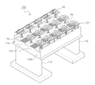
도면에 도시된 바와 같이, 본 발명의 제1실시예에 따른 생태 교량(100)은 서로 이격되게 배치되고 상면에 교좌 장치(113)가 설치된 한 쌍의 교대(110)와, 하부 플랜지(121a)와 이로부터 상방으로 연장된 한 쌍의 복부(121b)를 구비하여 그 단면의 상측에 개구부가 형성되는 U자 형상(120U)의 수용 공간(120c)이 형성되고 수용 공간(120c)에 격벽(124)을 구비하며 종방향으로 내설된 긴장재를 긴장시켜 프리스트레스가 도입되어 교대 상에 거치되는 'ㅛ'자형 거더(120)와, 'ㅛ'자형 거더(120)를 횡방향으로 연결시켜 상호간의 변위를 구속하는 가로보(128)와, 인접한 'ㅛ'자형 거더(120)의 복부(121b)끼리 그 상단부를 연결하도록 합성되는 바닥판(130)과, 'ㅛ'자형 거더(120)의 하부 플랜지(121a)와 복부(121b) 및 격벽(124)에 의해 둘러싸인 수용 공간(120c)과 바닥판(130)의 상측에 채워진 토사(55)를 포함하여 구성된다.As shown in the figure, the
즉, 본 발명은 U자 형상의 수용 공간이 형성되는 거더가 교대(110) 상에 거치되어 구성되는 데, 본 발명의 제1실시예는 제1거더와 제2거더가 모두 'ㅛ'자형 거더(120)로 이루어진다. That is, in the present invention, a girder in which a U-shaped accommodating space is formed is mounted on the
상기 교대(110)는 도6a에 도시된 바와 같이 서로 이격된 위치에 지상에 매설되는 기초(111)와, 기초(111)로부터 상방으로 연장된 벽체(112)와, 벽체(112)의 선단면에 거치된 교좌 장치(113)로 이루어진다. 생태 교량(100)의 배면의 토사가 교좌 장치(113)로 유입되는 것을 방지하도록 벽체(112)의 선단면에는 단턱(112a)이 형성된다. The
상기 'ㅛ'자형 거더(120)는 하부 플랜지(121a)와, 하부 플랜지(121a)의 양 끝단으로부터 이격된 위치에 상방으로 연장 형성된 한 쌍의 복부(121b)로 이루어진 'ㅛ'자형 콘크리트 (121)로 형성된다. 도면에는 복부(121b)가 수직으로 상방 연장 형성된 형태의 'ㅛ'자형 거더(120)를 예로 들었지만, 본 발명의 다른 실시형태에 따르면 복부(121b)는 하부 플랜지(121a)로부터 경사지게 상방 연장되어 형성될 수도 있다(이에 대해서도 'ㅛ'자형 거더(120)로 통칭한다). The 'ㅛ' -shaped
'ㅛ'자형 거더(120)의 내부에는 하부 플랜지(121a)와 복부(121b)에 종방향으로 내설된 긴장재(122)를 이용하여 프리스트레스를 'ㅛ'자형 거더(120)에 도입한다. 'ㅛ'자형 거더(120)의 하부 플랜지(121a)와 복부(121b)에는 다수의 강연선(122c)이 긴장재(122)의 일부로서 배치되어 강연선(122c)을 긴장하는 것에 의하여 압축 프리스트레스를 도입할 수 있다. The prestress is introduced into the 'ㅛ' -shaped
그리고 도9a에 도시된 바와 같이, 'ㅛ'자형 거더(120)에 압축 프리스트레스를 도입하는 긴장재(122) 중 다른 일부로서, 'ㅛ'자형 거더(120)의 복부(121b)에는 중립축의 상측에 직선 형태로 배열된 쉬스관에 압축용 강봉(122a)이 설치되고, 'ㅛ'자형 거더(120)의 중앙부에서 복부(121b)의 중립축의 하측을 통과하도록 포물선 형태로 배열된 쉬스관에 인장용 강연선(122b)이 설치되며, 압축용 강봉(122a)의 양단부와 인장용 강연선(122b)의 양단부를 수용하는 정착구(129)가 설치된다. 이 때, 도8a에 도시된 바와 같이 'ㅛ'자형 거더(120)의 중앙부에서는 인장용 강연선(122b, 122c)이 중립측 하연을 통과하도록 배열된다. And as shown in Figure 9a, as another part of the
이와 같이 긴장재(122)가 설치된 상태에서, 인장용 강연선(122b)을 잡아당기면, 이에 의한 반력으로 압축용 강봉(122a)의 끝단을 밀도록 작용하여 'ㅛ'자형 거더(120)의 중앙부의 중립축의 하측에는 압축 응력이 도입되고 중앙부의 중립축의 상측에는 인장 응력이 도입되어, 모멘트 프리스트레스를 도입할 수 있게 된다. 그리고, 정착구(129)가 위치하는 블록 아웃된 영역은 휨 변위를 도입한 이후에 현장타설 콘크리트(121c)로 매워진다. 도7에는 도시되지 않았지만, 'ㅛ'자형 거더(120)의 양단부는 정착구(129)를 수용하는 블록아웃된 영역이 도9a에 도시된 바와 같이 형성될 수 있다. As such, when the
한편, 'ㅛ'자형 거더(120)의 복부(121b)는 공용 중 상단부에 큰 압축 응력이 작용하므로, 도8b에 도시된 바와 같이, 제1거더(120')의 복부(121b')의 상단부는 단면이 확장되게 형성되어, 공용 중 거더 상측에 작용하는 큰 압축 응력을 보다 효과적으로 상쇄시킬 수 있다. 이 때, 콘크리트로 형성되는 제1거더(120')의 복부(121b')는 국부적인 응력이 크게 작용하는 것을 방지하고 제작용 거푸집의 설치를 용이하게 하도록 종방향 전체에 걸쳐 일정한 단면으로 복부 상단부의 단면이 확장되게 형성되는 것이 좋다. On the other hand, the abdomen 121b of the '공용' -shaped
'ㅛ'자형 거더(120)의 복부(121b)의 상단부에는 바닥판 연결철근(123)이 상방으로 돌출 형성되어, 바닥판(130)의 내부에 배근된 바닥판 철근(미도시)과 결속되고 동시에 'ㅛ'자형 거더(120)의 상측에 합성되는 바닥판 콘크리트에 덮이게 됨으로써, 'ㅛ'자형 거더(120)와 바닥판(130)이 보다 견고하게 결합되도록 한다. At the upper end of the abdomen 121b of the 'ㅛ' -shaped
'ㅛ'자형 거더(120)는 도7에 도시된 바와 같이, 가로보(128)가 연결되는 위치의 복부(121b)사이와 하부 플랜지(121a)를 연결하는 격벽(124)이 'ㅛ'자형 거더(120)의 제작 시에 미리 형성된다. 이를 통해, 격벽(124)과 하부플랜지(121a) 및 복부(121b)에 의해 둘러싸이는 공간에 토사를 채움으로써 1.5m이상의 두께를 갖는 식생층을 형성할 수 있다. 이 때, 토사(55)로부터 빗물을 배출할 수 있는 배수공(124a)이 격벽(124)에 관통 형성되며, 가로보(128)는 'ㅛ'자형 거더(120)의 전후면을 폐합되도록 'ㅛ'자형 거더(120)의 양단부를 포함하는 위치에서 복부(121b)를 상호 연결하도록 시공된다. As shown in Fig. 7, the 'ㅛ' -shaped
그리고, 생태 교량(120)의 최외측 'ㅛ'자형 거더(120)의 바깥측 복부의 상측에는 바닥판 콘크리트를 'ㅛ'자형 거더(120)와 합성할 때에 토사(55)가 흘러내리는 것을 방지하기 위하여 보다 높은 높이(L)만큼 단턱(129)이 합성된다. And, on the upper side of the outer abdomen of the outermost 'ㅛ' -shaped
한편, 상기와 같이 구성된 'ㅛ'자형 거더(120)는 하부 플랜지(121a)가 복부(121b)의 위치로부터 양측 방향으로 연장 형성됨에 따라, 단면 계수가 높아져 비틀림 변위나 하방으로 휘는 변위에 저항하는 데 보다 효과적일 뿐만 아니라, 횡방향으로 인접한 'ㅛ'자형 거더(120)들 사이를 횡방향으로 연결하여 구속하는 가로보(128)의 설치가 보다 용이해진다.On the other hand, the 'ㅛ' -shaped
그리고, 도7에 도시된 바와 같이 가로보(128)가 설치되는 'ㅛ'자형 거더(120)의 복부(121b)의 양측면에는 가로보 연결철근(126)이 횡방향으로 돌출 형성된다. 'ㅛ'자형 거더(120)의 복부(121b)의 바깥 측면(인접한 다른 거더에 대향하는 면)에 돌출된 가로보 연결철근(126)은 가로보(128)에 배근되는 철근과 결속되도록 설치되어 보다 완전한 합성을 보조한다. Then, as shown in Figure 7, the cross beam connecting reinforcing
일반적으로 교대(110) 상에 시공되는 교량은 공용 중에 경간 중앙부에 큰 응력이 작용한다. 특히, 교량에 작용하는 하중을 지지하는 거더는 경간 중앙부에서 상연부에 큰 압축 응력이 작용한다. 따라서, 본 발명의 다른 실시형태에 따른 생태교량의 제1거더(120')는 경간 중앙부의 상측에 크게 작용하는 응력에 견딜 수 있도록 제1거더(120')의 복부(121b')의 상단부는 보다 확대된 단면으로 형성될 수 있다.
In general, a bridge constructed on the
상기 가로보(128)는 횡방향으로 인접 배열된 'ㅛ'자형 거더(120)의 복부(121b)의 바깥면에 노출된 가로보 연결철근(126)과 견고하게 결속되도록 'ㅛ'자형 거더(120)를 횡방향으로 연결한다. 이에 의하여, 도6c에 도시된 바와 같이 본 발명에 따른 생태 교량(100)은 종방향으로는 복부(121b)에 의해 연속하는 열을 형성하며 교량에 작용하는 하중을 지지하고, 횡방향으로는 가로보(128)와 격벽(124)에 의해 연속하는 열을 형성하며 교량에 작용하는 하중을 지지하므로, 자중과 외력에 대하여 완전한 판거동을 구현하여 보다 높은 하중이 국부적으로 작용하더라도 횡방향으로 이격된 다른 거더(120)에 의하여 그 힘을 효과적으로 지지할 수 있다. The
그리고, 가로보(128)는 'ㅛ'자형 거더(120)가 교대(110) 상에 거치된 상태에서 현장 시공된다. 교대(110) 상에 거치된 'ㅛ'자형 거더(120)는 복부(121b)에 대하여 외향 돌출된 하부 플랜지(121a)를 구비함에 따라, 작업자가 외향 돌출된 하부 플랜지(121a)상에서 추락의 위험이 없이 하부 플랜지(121a)에 지지되도록 거푸집(미도시)을 설치하고 하부 플랜지(121a)에 의해 지지되도록 가로보(128)를 시공하게 된다. 따라서, 가로보(128)를 매우 용이하게 시공할 수 있다. In addition, the
이를 위하여, 교대(110) 상에 거치되는 'ㅛ'자형 거더(120)는 그 하부플랜지(121a) 사이의 간격(c)이 작업자가 추락하지 않는 대략 10cm 내외의 간격 정도로만 이격시키는 것이 좋다.
To this end, the 'ㅛ' shaped
상기 바닥판(130)은 도6d에 도시된 바와 같이 교대(110)상에 거치된 'ㅛ'자형 거더(120)의 한 쌍의 복부(121b)가 이루는 수용 공간(120c)은 개방되면서 인접한 거더(120)와 이루는 사잇 공간(130c)의 상측은 폐합되도록 복부(121b)의 상단부를 서로 연결하는 것에 의하여 시공된다. 즉, 바닥판(130)은 인접한 서로 다른 'ㅛ'자형 거더(120)의 복부(121b)를 연결할 뿐, 교대(110)에 다수의 열로 배열된 'ㅛ'자형 거더(120)에 형성된 한 쌍의 복부(121b)의 상단부를 서로 연결하지 않는다. The
'ㅛ'자형 거더(120)의 하부 플랜지(121a) 및 한 쌍의 복부(121b)와 격벽(124)으로 둘러싸인 공간(120c)은 토사(55)가 채워질 수 있도록 상방이 개방된 상태가 되고, 'ㅛ'자형 거더(120)의 사잇 공간(130c)는 바닥판(130)의 하측에 빈공간으로 남게 된다. 그리고, 토사(55)가 'ㅛ'자형 거더(120)의 수용 공간(120c)에 채워지고, 추가적으로 바닥판(130)과 상기 수용공간(120c)의 상측 공간에 채워짐으로써, 수목이 자랄 수 있는 식생층을 형성한다.The
이를 통해, 'ㅛ'자형 거더(120)의 수용 공간(120c)에서 토사가 채워져 나무(45)가 자랄 수 있는 1.5m이상의 두꺼운 두께(H')의 토사로 이루어진 식생층과, 바닥판(130)의 상측 공간에서는 풀(44)이 자랄 수 있는 얇은 두께(H")의 토사로 이루어진 식생층이 각각 형성되어, 야생 동물들이 편안하게 통행할 수 있는 나무(45)와 풀(44)로 이루어진 생태 통로를 형성한다.
Through this, the soil layer in the receiving space (120c) of the 'ㅛ' -shaped
이하, 상기와 같이 구성된 본 발명에 따른 생태 교량의 시공 방법을 상술한다.
Hereinafter, the construction method of the ecological bridge according to the present invention configured as described above will be described in detail.
단계 1: 먼저 도7에 도시된 바와 같이, 폭이 길게 형성된 하부 플랜지(121a)와, 하부 플랜지(121a)의 양 끝단으로부터 이격된 위치에 상방으로 연장 형성된 한 쌍의 복부(121b)로 이루어진 'ㅛ'자형 콘크리트(121)를 제작한다. 이 때, 복부(121b)의 상측으로 바닥판 연결철근(123)이 돌출되고 복부(121b)의 측방향으로도 가로보 연결철근(126)이 돌출되도록 콘크리트(121)의 내부에 철근을 배근한다. 이 때, 한 쌍의 복부(121b) 사이에는 거더(120)의 양단 및 중앙부에 격벽(124)이 미리 형성된다. 격벽(124)은 'ㅛ'자형 거더(120)의 제작시에 함께 일체로 제작될 수도 있지만, 후술하는 가로보(128)의 설치 시에 'ㅛ'자형 거더(120)에 합성될 수도 있다. Step 1 : First, as shown in FIG. 7, the
그리고, 도8a 내지 9a에 도시된 궤적으로 인장용 강연선(122c)이 하부플랜지(121a) 및 복부(121b)의 쉬스관 내에 설치되며, 선택적으로 압축용 강봉(122a)과, 이에 대응되는 인장용 강연선(122b)이 추가적으로 배치되는 것도 가능하다. 8A to 9A, the
이 때, 복부(121b)의 상단부에 작용하는 압축 응력을 효과적으로 견디기 위하여 도8b에 도시된 바와 같이 복부(121b') 상단부의 단면을 확대시킨 상태로 'ㅛ'자형 거더(120)를 제작할 수도 있다.
In this case, in order to effectively withstand the compressive stress acting on the upper end of the abdomen 121b, the 'ㅛ' shaped
단계 2: 그 다음, 'ㅛ'자형 거더(120)의 하부 플랜지(121a)와 복부(121b)에 종방향으로 내설된 긴장재(122)를 긴장시켜 콘크리트 'ㅛ'자형 거더(120)에 압축 프리스트레스를 도입한다. 보다 구체적으로는, 강연선(122c)을 긴장시켜 'ㅛ'자형 거더(120)에 압축 프리스트레스를 도입한다. 그리고, 필요한 경우에 인장용 강연선(122b)을 잡아당기는 것에 의한 반력으로 정착구(129)가 압축용 강봉(122a)의 끝단을 밀도록 작용하여, 'ㅛ'자형 거더(120)의 복부 중앙부의 중립축의 하측에는 압축 응력이 도입되고, 복부 중앙부의 중립축의 상측에는 인장 응력을 도입시키는 구성을 추가할 수도 있다.
Step 2 : Then, the pre-stress is compressed to the concrete 'ㅛ' -shaped
단계 3: 도6a에 도시된 바와 같이, 생태 교량(100)을 가설하고자 하는 위치에 서로 이격되게 배치되는 교대(110)를 설치한다. 단계 3은 단계 1 및 2와 동시에 행해질 수도 있으며, 단계 1 및 2보다 먼저 행해질 수도 있다. Step 3 : As shown in Figure 6a, install the
단계 4 그리고 나서, 도6b에 도시된 바와 같이 단계 2에서 제작된 'ㅛ'자형 거더(120)는 교대(110)의 교좌 장치(113)의 상측에 다수의 열로 거치된다. 횡방향으로 인접한 'ㅛ'자형 거더(120)는 그 하부 플랜지(121a)의 간격(c)이 대략 10cm 내외로 유지되는 것이 좋다. 이를 통해, 'ㅛ'자형 거더(120)의 바깥으로 돌출된 하부 플랜지(121a) 상에서 작업자가 하부 플랜지(121a)의 간격(c)사이로 추락하는 것을 방지할 수 있다. 다만, 미리 정해진 치수의 'ㅛ'자형 거더(120)를 다양한 폭의 교량에 적용하는 데 있어서, 상기 간격(c)이 대략 25cm 내지 30cm 보다 큰 경우로 시공되는 경우에는, 작업자의 안전을 위하여 하부 플랜지(121a)의 돌출부 상에 추락방지용 발판을 거치시킬 수도 있다.
Step 4 Then, as shown in FIG. 6B, the 'ㅛ' shaped
단계 5: 복부(121b)로부터 양측으로 돌출된 하부 플랜지(121a) 상에서 작업자는 가로보(128)를 시공하기 위한 가로보 거푸집(미도시)을 설치한다. 이 거푸집은 복부(121b)로부터 양측으로 돌출된 하부 플랜지(121a) 상에 지지되도록 설치되므로 가로보 거푸집의 설치가 매우 용이해진다. 가로보 거푸집에 굳지 않은 콘크리트를 타설하여 도6c에 도시된 바와 같이 가로보(128)를 횡방향으로 인접한 'ㅛ'자형 거더(120)에 연결 합성시킨다. 이 때, 횡방향으로 인접한 'ㅛ'자형 거더(120)를 연결하는 가로보(128)도 역시 바닥면이 복부(121b)로부터 양측으로 돌출된 하부 플랜지(121a) 상에 지지되도록 설치된다. Step 5 : On the
가로보(128)는 'ㅛ'자형 거더(120)의 한 쌍의 복부(121b)를 연결하는 격벽(124)과 횡방향으로 연속한 열을 이루는 위치에 합성된다. 따라서, 가로보(128)와 격벽(124)에 의하여 교량(100)의 상부구조는 종방향으로는 복부(121b)에 의하여 횡방향으로는 가로보(128)와 격벽(124)에 의하여 격자형 판구조가 되어, 교량(100)의 상부구조에 작용하는 외력을 효과적으로 지지할 수 있게 된다.
The
단계 6: 그 다음, 도6d에 도시된 바와 같이, 교대(110) 상에 다수의 열로 거치된 'ㅛ'자형 거더(120)의 한 쌍의 복부(121b) 중 하나의 상단부와 이와 횡방향으로 인접한 다른 'ㅛ'자형 거더(120)의 한 쌍의 복부(121b) 중 하나의 상단부를 연결하도록 바닥판 거푸집(미도시)을 설치한 후, 바닥판 철근을 바닥판 연결철근(123)과 결속시키고 나서 바닥판 거푸집에 굳지 않은 콘크리트를 타설하여 'ㅛ'자형 거더(120)에 바닥판(130)을 합성시킨다. 이와 동시에, 생태 교량(120)의 최외측 'ㅛ'자형 거더(120)의 바깥측 복부의 상측에는 바닥판 콘크리트를 'ㅛ'자형 거더(120)와 합성할 때에 토사(55)가 흘러내리는 것을 방지하기 위하여 보다 높은 높이(L)만큼 단턱(129)을 'ㅛ'자형 거더(120)의 최외측 복부(121b)의 선단면에 합성한다. Step 6 : Then, as shown in FIG. 6D, in the transverse direction with the upper end of one of the pair of abdomen 121b of the 'ㅛ'
'ㅛ'자형 거더(120) 간의 사잇 공간(130c)은 바닥판(130)의 시공에 의하여 빈 공간으로 남게 되면서 그 상측이 완전히 폐합된다. 이 때, 단계 6은 단계 5와 동시에 행해질 수도 있다.
The
단계 7: 바닥판(130)이 'ㅛ'자형 거더(120)에 충분한 강도로 합성되면, 교대(110)의 배면에 토사를 채움과 동시에, 도6e에 도시된 바와 같이 'ㅛ'자형 거더(120)의 수용공간(120c)에 자갈(55')과 토사(55)를 채우고, 바닥판(130)의 상측에도 토사(55)를 덮는다. 그리고 나서, 도11에 도시된 바와 같이, 수용 공간(120c)에 채워진 토사(55)는 1.5m 이상의 충분한 두께(H')로 형성되므로 깊게 뿌리를 내리는 나무(45) 등을 심고, 바닥판(130)의 상측에 덮혀진 토사(55)는 상대적으로 얕은 두께(H")로 형성되므로 얕은 깊이로 뿌리를 내리는 풀(44)등을 심어, 야생 동물들이 편안하게 왕래할 수 있는 환경을 생태 교량(100)의 상부 표면에 조성한다.
Step 7 : When the
상기와 같이 시공되는 생태 교량(100)에 있어서 지점부의 구조에 대한 일례는 다음과 같다. 즉, 도10에 도시된 바와 같이 배수공(124a)으로부터 배출된 우수가 r1으로 표시된 경로로 흘러 내려오더라도 거더(120)의 요홈(120g)이나 유수 차단턱(140)에서 하방(r2, r3)으로 낙하하게 되어, 교대(110)의 벽체(112)에 도달하는 것이 방지되므로, 우수에 의하여 벽체(112) 등에 얼룩이 생기는 것을 방지할 수 있게 된다.
An example of the structure of the branch portion in the
상기와 같이 시공된 생태 교량(100)은 생태 교량(100)의 상부 표면은 모두 토사(55)와 풀(44), 나무(45)로 뒤덮어 야생 동물이 편안하게 왕래할 수 있는 환경이 충족되면서, 'ㅛ'자형 거더(120)의 사잇 공간(130c)은 빈공간으로 남겨짐에 따라 보다 가벼운 생태 교량을 구현할 수 있다. 또한, 본 발명에 따른 생태 교량(100)은 1.5m이상의 식생층을 형성하는 토사(55)가 'ㅛ'자형 거더(120)의 수용 공간(120c)에 채워지도록 구성됨으로써, 식생층의 형성높이(h2)와 'ㅛ'자형 거더(120)의 높이가 서로 중첩 배치되므로, 생태 통로의 상면 계획고(H)를 낮출 수 있는 장점을 얻을 수 있다. 무엇보다도, 이와 같이 상면 계획고(H)를 낮추면서도, 'ㅛ'자형 거더(120), 가로보(128), 바닥판(130)의 상호간의 시공 이음부가 견고하게 결합됨으로써 종래의 생태 교량의 시공 이음부에서 누수 현상이 발생되던 문제점을 해결할 수 있다. 따라서, 생태 교량의 유지 관리를 최소화하면서도 장기간 동안 깨끗한 교량 상태를 유지할 수 있는 잇점을 얻을 수 있다.
The construction of the
이하, 본 발명의 제2실시예에 따른 생태 교량(200)을 상술한다. 다만, 전술한 제1실시예의 구성과 유사한 구성에 대해서는 동일 또는 유사한 도면 부호를 부여하고 이에 대한 설명은 제2실시예의 요지를 명료하게 하기 위하여 생략하기로 한다. Hereinafter, the
도12에 도시된 바와 같이, 본 발명의 제2실시예에 따른 생태 교량(200)은 서로 이격되게 배치되고 상면에 교좌 장치(113)가 설치된 한 쌍의 교대(110)와, 단면의 상측에 개구부가 형성되는 U자 형상(220U)의 수용 공간이 형성되고 수용 공간에 격벽을 구비하며 종방향으로 내설된 긴장재를 긴장시켜 프리스트레스가 도입되어 교대(110) 상에 거치되는 제1거더(220)와, 제1거더(220)로부터 횡방향으로 이격된 위치에 제1거더(220)의 복부(221b)와 대응하는 높이로 형성된 I형 콘크리트 거더의 형태로 교대(110)상에 거치되는 제2거더(280)와, 제1거더(220)의 한쌍의 복부가 이루는 개구부는 개방되면서 횡방향으로 인접한 제2거더(280)와의 사잇 공간(230c)의 상측은 폐합되도록 제1거더(220)의 복부 상단부와 제2거더(280)의 상단부를 서로 연결하여 형성되는 바닥판(230)과, 제1거더(220)와 횡방향으로 인접한 제2거더(280)의 사잇 공간(230c)의 전후면이 폐합되도록 양단부 위치에서 제1거더(220)의 복부와 제2거더(280)의 복부(221b)를 연결하는 가로보(미도시)와, 제1거더(220)의 수용 공간의 일부 이상에 단턱(229)보다 낮은 높이로 채워진 토사(55)를 포함하여 구성된다.As shown in FIG. 12, the
즉, 본 발명은 U자 형상(220U)의 수용 공간이 형성되는 제1거더(220)와 토사(55)가 채워지는 수용 공간이 형성되지 않는 제2거더(280)가 교대(110) 상에 거치되어 구성될 수 있다. 이 때, 제1거더(220)는 한 쌍의 I자형 콘크리트 거더(221)와 한 쌍의 I자형 콘크리트 거더(221)의 하부를 연결하는 연결판(222)을 포함하여 구성된다. 여기서, I자형 콘크리트 거더(221)는 상부 플랜지(221u)와 하부 플랜지(221d)와 이들(221u, 221d)을 연결하는 복부(221b)로 이루어진다. 즉, 제1거더(220)는 한 쌍의 I자형 콘크리트 거더(221)과 연결판(222)으로 이루어져 2개 이상의 거더로 구성된다. 또한, 한 쌍의 I자형 콘크리트 거더(221)과 연결판(222)으로 이루어진 제1거더(220)는 지상에서 완성되어 교대(110)에 거치되지 않고, 한 쌍의 I자형 콘크리트 거더(221)가 교대(110) 상에 거치된 후 연결판(222)으로 연결하는 것에 의하여 비로소 완성될 수도 있다. 즉, 제1거더(220)는 교대(110)상에서 제작이 완료될 수도 있다. That is, in the present invention, the
이 때, 연결판(222)은 미리 제작된 프리캐스트 형태로 제작되어 I자형 콘크리트 거더(221)의 하부 플랜지(221d)에 걸려 거치되는 것이 바람직하고, 연결판(222)과 I자형 콘크리트 거더(221)의 사이의 이음부는 충전재로 방수 처리될 수 있다. 이를 통해, U자 형상(220u)의 수용공간은 누수 가능성이 최소화되면서 보다 간편하게 시공될 수 있다. At this time, it is preferable that the connecting
한편, 도12에는 제1거더(220)와 제2거더(280)의 사잇 공간(230c)의 상측을 폐합하는 바닥판(230)이 제2거더(280)의 상측을 연속하여 연장된 형태로 형성되는 구성을 예로 들었지만, 제2거더(280)의 상측에서 불연속인 2개의 바닥판(230)으로 구분되어 형성될 수도 있다.
Meanwhile, in FIG. 12, the
이하, 본 발명의 제3실시예에 따른 생태 교량(300)을 상술한다. 다만, 전술한 제1실시예의 구성과 유사한 구성에 대해서는 동일 또는 유사한 도면 부호를 부여하고 이에 대한 설명은 제3실시예의 요지를 명료하게 하기 위하여 생략하기로 한다. Hereinafter, the
도13에 도시된 바와 같이, 본 발명의 제3실시예에 따른 생태 교량(300)은 서로 이격되게 배치되고 상면에 교좌 장치(113)가 설치된 한 쌍의 교대(110)와, 단면의 상측에 개구부가 형성되는 U자 형상(120U)의 수용 공간이 형성되고 수용 공간에 격벽을 구비하며 종방향으로 내설된 긴장재를 긴장시켜 프리스트레스가 도입되어 교대(110) 상에 거치되는 제1거더(120)와, 제1거더(120)로부터 횡방향으로 이격된 위치에 제1거더(120)의 복부와 대응하는 높이로 형성된 I형 콘크리트 거더의 형태로 교대(110)상에 거치되는 제2거더(380)와, 제1거더(120)의 한쌍의 복부가 이루는 개구부는 개방되면서 횡방향으로 인접한 제2거더(380)와의 사잇 공간(330c)의 상측은 폐합되도록 제1거더(120)의 복부 상단부와 제2거더(380)의 상부 플랜지를 서로 연결하여 형성되는 바닥판(330)과, 제1거더(120)와 횡방향으로 인접한 제2거더(380)의 사잇 공간(330c)의 전후면이 폐합되도록 양단부를 포함하는 위치에서 제1거더(120)의 복부와 제2거더(380)의 복부를 연결하는 가로보(미도시)와, 제1거더(120)의 수용 공간의 일부 이상에 단턱(129)보다 낮은 높이로 채워진 토사(55)를 포함하여 구성된다.As shown in Fig. 13, the
즉, 본 발명은 U자 형상의 수용 공간이 형성되는 제1거더(120)가 제1실시예에서 설명한 'ㅛ'자형 거더로 형성되고, 제2거더(380)가 그 사이에 위치할 수도 있다. 도13에는 제1거더(120)의 사이에 제2거더(380)가 1개 위치한 구성을 예로 들었지만, 제1거더(120)의 사이에 제2거더(380)가 다수개 위치할 수도 있다.That is, in the present invention, the
한편, 도13에는 제1거더(120)와 제2거더(380)의 사잇 공간(330c)의 상측을 폐합하는 바닥판(330)이 제2거더(380)의 상측을 연속하여 연장된 형태로 형성되는 구성을 예로 들었지만, 제2거더(380)의 상측에서 불연속인 2개의 바닥판(330)으로 구분되어 형성될 수도 있다.
Meanwhile, in FIG. 13, the
이하, 본 발명의 제4실시예에 따른 생태 교량(400)을 상술한다. 다만, 전술한 제1실시예의 구성과 유사한 구성에 대해서는 동일 또는 유사한 도면 부호를 부여하고 이에 대한 설명은 제4실시예의 요지를 명료하게 하기 위하여 생략하기로 한다. Hereinafter, the
도14에 도시된 바와 같이, 본 발명의 제4실시예에 따른 생태 교량(400)은 서로 이격되게 배치되고 상면에 교좌 장치(113)가 설치된 한 쌍의 교대(110)와, 단면의 상측에 개구부가 형성되는 U자 형상의 수용 공간이 형성되고 수용 공간에 격벽을 구비하며 종방향으로 내설된 긴장재를 긴장시켜 프리스트레스가 도입되어 교대(110) 상에 거치되는 제1거더(120)와, 제1거더(120)로부터 횡방향으로 이격된 위치에 제1거더(120)의 복부와 대응하는 높이로 형성된 I형 콘크리트 거더의 형태로 교대(110)상에 교량(400)의 횡방향으로의 끝단에 이르도록 다수 거치되는 제2거더(480)와, 제1거더(120)의 한쌍의 복부가 이루는 개구부는 개방되면서 횡방향으로 인접한 제2거더(480)와의 사잇 공간(430c)의 상측은 폐합되도록 제1거더(120)의 복부 상단부와 제2거더(480)의 상부 플랜지를 서로 연결하여 형성되는 바닥판(430)과, 제1거더(120)와 횡방향으로 인접한 제2거더(480)의 사잇 공간(430c)의 전후면이 폐합되도록 양단부를 포함하는 위치에서 제1거더(120)의 복부와 제2거더(480)의 복부를 연결하는 가로보(미도시)와, 제1거더(120)의 수용 공간의 일부 이상에 단턱(129, 429)보다 낮은 높이로 채워진 토사(55)를 포함하여 구성된다.As shown in FIG. 14, the
즉, 본 발명의 제4실시예는 U자 형상의 수용 공간이 형성되는 제1거더(120)가 제1실시예에서 설명한 'ㅛ'자형 거더로 형성되고, 제2거더(480)가 그 일측에 교량의 끝단에 이르도록 다수 위치한다. 도14에는 제1거더(120)와 제2거더(480)의 사잇 공간(430c)의 상측을 폐합하는 바닥판(430)이 제2거더(480)의 상측을 연속하여 연장된 형태로 형성되는 구성을 예로 들었지만, 제2거더(480)의 상측에서 불연속인 2개의 바닥판(330)으로 구분되어 형성될 수도 있다.
That is, in the fourth embodiment of the present invention, the
이상에서는 본 발명의 바람직한 실시예를 예시적으로 설명하였으나, 본 발명의 범위는 이와 같은 특정 실시예에만 한정되는 것은 아니며, 특허청구 범위에 기재된 범주 내에서 적절하게 변경 가능한 것이다. 예를 들어, 상기 실시예에서는 'ㅛ'자형 거더(120)에 압축 프리스트레스를 도입하는 시점이 교대(110)에 거치하기 이전으로 예를 들었으나, 교대(110)에 거치한 이후에도 추가적으로 압축 프리스트레스를 도입할 수 있다. 또한, 위 실시예에서는 하부 플랜지(121a)와 복부(121b)에 모두 긴장재(122)가 내설된 구성을 예로 들었으나, 하부플랜지(121a)와 복부(121b) 중 어느 하나에만 긴장재(122)가 내설될 수도 있다. In the above, the preferred embodiments of the present invention have been described by way of example, but the scope of the present invention is not limited to these specific embodiments, and may be appropriately changed within the scope described in the claims. For example, in the above embodiment, although the time point at which the compression prestress is introduced into the 'ㅛ' -shaped
또한, 상기 실시예에서는 가로보(128)를 설치하는 단계 5와 바닥판(130) 및 단턱(129)을 설치하는 단계 6이 순차적으로 이루어지는 경우를 예로 들었지만, 가로보(128)와 바닥판 콘크리트(130)를 합성하는 단계는 동시에 이루어질 수도 있다. 이를 통해, 본 발명에 따른 생태 교량(100)의 시공 공정을 보다 단순화할 수 있는 장점을 얻을 수 있다.
In addition, in the above embodiment, although the step 5 of installing the
100, 200, 300, 400: 생태 교량 110: 교대
120: 'ㅛ'자형 거더 121a: 하부 플랜지
121b: 복부 122: 긴장재
124: 격벽 128: 가로보
129, 229, 429: 단턱 130: 바닥판
55: 토사 220: 제1거더
280, 380, 480: 제2거더100, 200, 300, 400: Ecological bridge 110: Shift
120: 'ㅛ' girder 121a: lower flange
121b: Abdomen 122: Tension
124: partition 128: crossbeam
129, 229, 429: step 130: bottom plate
55: Tosa 220: First girder
280, 380, 480: second girder
Claims (15)
상기 제1거더의 복부와 대응하는 높이로 형성되고, 내부에 설치된 긴장재를 긴장시켜 프리스트레스가 도입되고 상기 제1거더로부터 횡방향으로 이격된 위치의 상기 교대 상에 거치되는 제2거더와;
상기 제1거더의 한쌍의 복부가 이루는 상기 개구부는 개방되면서 횡방향으로 인접한 상기 제2거더와의 사잇 공간의 상측은 폐합되도록 상기 제1거더의 복부 상단부와 상기 제2거더의 상단부를 서로 연결하여 형성되는 바닥판과;
상기 제1거더의 수용 공간에 채워진 토사를;
포함하여 구성된 것을 특징으로 하는 생태 교량의 상부구조.
A pair of abdominal portions extending upward, a U-shaped accommodating space in which an opening is formed at an upper side of the cross-section is formed, and a prestress is introduced and mounted on the alternating tension by tensioning the tension member in the longitudinal direction; 1 girder;
A second girder formed at a height corresponding to the abdomen of the first girder and being prestressed by tensioning a tension member installed therein and mounted on the alternation at a position spaced laterally from the first girder;
The opening of the pair of abdomen of the first girder is opened and the upper side of the abdomen upper portion of the first girder and the upper end of the second girder are connected to each other so that the upper side of the interspace with the second girder laterally adjacent to each other is closed. A bottom plate formed;
Earth and sand filled in the accommodation space of the first girder;
Superstructure of ecological bridges, characterized in that configured to include.
상기 제1거더의 수용 공간에는 한 쌍의 복부를 포함하는 3면에 결합되도록 격벽이 설치되고, 상기 격벽과 횡방향으로 연속하도록 상기 제1거더의 복부와 상기 제2거더의 일면을 연결하는 가로보가 설치된 것을 특징으로 하는 생태 교량의 상부구조.
The method of claim 1,
A partition wall is installed in the accommodation space of the first girder so as to be coupled to three surfaces including a pair of abdomen, and a cross beam connecting the abdomen of the first girder and one surface of the second girder so as to continuously cross the partition wall. The superstructure of the ecological bridge, characterized in that the installation.
상기 제1거더는 한 쌍의 I자형 콘크리트 거더와, 상기 한 쌍의 I자형 콘크리트 거더의 하부를 연결하는 연결판을 포함하도록 구성되어, 그 단면이 상측에 개구부가 형성된 U자 형상의 수용공간을 구비하는 것을 특징으로 하는 생태 교량의 상부구조.
The method of claim 2,
The first girder is configured to include a pair of I-shaped concrete girder and a connecting plate connecting the lower portion of the pair of I-shaped concrete girder, the cross section of the U-shaped receiving space having an opening formed on the upper side An upper structure of the ecological bridge, characterized in that provided.
상기 제2거더는 그 단면이 I자형 콘크리트 거더로 형성된 것을 특징으로 하는 생태 교량의 상부구조.
The method of claim 2,
The second girder is an upper structure of an ecological bridge, characterized in that the cross section is formed of I-shaped concrete girder.
상기 제2거더는 그 단면이 상측에 개구부가 형성되는 U자 형상의 수용 공간이 형성되도록 구성된 것을 특징으로 하는 생태 교량의 상부구조.
The method of claim 2,
The second girder is an upper structure of an ecological bridge, characterized in that the cross-section is configured to form a U-shaped receiving space in which the opening is formed on the upper side.
상기 제1거더와 상기 제2거더 중 어느 하나 이상은 하부 플랜지의 양 끝단으로부터 이격된 위치에 한 쌍의 복부가 상방으로 연장되어 'ㅛ'자형 거더로 형성된 것을 특징으로 하는 생태 교량의 상부구조.
The method according to any one of claims 1, 2, 4, and 5,
At least one of the first girder and the second girder is a superstructure of the ecological bridge, characterized in that the pair of the abdomen is extended upwards in a position spaced apart from both ends of the lower flange formed of a 'ㅛ' girder.
상기 'ㅛ'자형 거더는 상기 복부의 상단부의 단면이 확장되게 형성된 것을 특징으로 하는 생태 교량의 상부구조.
The method of claim 6,
The 'ㅛ' shaped girder is an upper structure of the ecological bridge, characterized in that the upper end of the abdomen is formed to extend.
상기 제1거더의 복부와 대응하는 높이로 형성되고, 내설된 긴장재를 긴장 정착하여 프리스트레스가 도입된 제2거더를 상기 제1거더와 횡방향으로 이격된 위치의 교대 상에 거치시키는 제2거더 설치단계와;
상기 제1거더의 한쌍의 복부가 이루는 상기 개구부는 개방되면서 횡방향으로 인접한 상기 제2거더와의 사잇 공간의 상측은 폐합되도록 상기 제1거더의 상기 복부의 상단부와 상기 제2거더의 상단부를 바닥판으로 서로 연결 설치하는 바닥판 설치단계와;
상기 제1거더의 하부 플랜지와 복부에 의해 둘러싸인 상기 수용 공간에 토사를 채우고 상기 바닥판의 상면에 토사를 덮는 토사채움단계를;
포함하여 제작되는 것을 특징으로 하는 생태교량의 시공 방법.
A U-shaped accommodating space is provided having a pair of abdomen extending upwards and an opening is formed in the upper side of the cross section, and the first girder of the U-shaped cross section in which the prestress is introduced by tension-fixing the insulated tension member Installing the first girder to be mounted on the shift;
The second girder is formed at a height corresponding to the abdomen of the first girder, and the second girder is mounted on the alternating position of the second girder in which the prestress is introduced to alternately spaced apart from the first girder. Steps;
The upper end of the abdomen of the first girder and the upper end of the second girder are closed so that the opening of the pair of abdomen of the first girder is opened while the upper side of the site with the second girder is laterally closed. A bottom plate installation step of connecting and installing each other with plates;
A soil filling step of filling the earth and sand in the accommodation space surrounded by the lower flange and the abdomen of the first girder and covering the earth and sand on the upper surface of the bottom plate;
Construction method of an ecological bridge, characterized in that the production.
상기 제1거더의 수용 공간에는 한 쌍의 복부를 포함하는 3면에 결합되는 격벽설치단계와;
상기 격벽과 횡방향으로 연속하도록 상기 제1거더의 복부와 상기 제2거더의 일면을 연결하는 가로보 설치단계를;
추가적으로 포함하여 제작되는 것을 특징으로 하는 생태교량의 시공 방법.
The method of claim 8,
A partition wall installation step coupled to three surfaces including a pair of abdominals in the accommodation space of the first girder;
A cross beam installing step of connecting the abdomen of the first girder and one surface of the second girder so as to be continuous with the partition wall in a transverse direction;
Construction method of the ecological bridge, characterized in that the additional production.
상기 제1거더는 한 쌍의 I자형 콘크리트 거더와, 상기 한 쌍의 I자형 콘크리트 거더의 하부를 연결하는 연결판을 포함하도록 구성되어, 그 단면이 상측에 개구부가 형성된 U자 형상의 수용공간을 구비하도록 제작되는 것을 특징으로 하는 생태 교량의 시공 방법.
The method of claim 9,
The first girder is configured to include a pair of I-shaped concrete girder and a connecting plate connecting the lower portion of the pair of I-shaped concrete girder, the cross section of the U-shaped receiving space having an opening formed on the upper side Construction method of the ecological bridge, characterized in that it is produced to have.
상기 제2거더는 I자형 콘크리트 거더로 형성되도록 제작된 것을 특징으로 하는 생태 교량의 시공 방법.
The method of claim 9,
The second girder construction method of the ecological bridge, characterized in that it is made to be formed of I-shaped concrete girder.
상기 제2거더는 그 단면이 상측에 개구부가 형성되는 U자 형상의 수용 공간이 형성되도록 제작된 것을 특징으로 하는 생태 교량의 시공 방법.
The method of claim 9,
The second girder construction method of the ecological bridge, characterized in that the cross-section is formed so that the U-shaped receiving space is formed in the opening is formed on the upper side.
상기 제1거더와 상기 제2거더 중 어느 하나 이상은 상기 한 쌍의 복부가 상기 하부 플랜지의 양 끝단으로부터 이격된 위치에 상방으로 연장 형성되어 'ㅛ'자형 단면의 거더로 제작되는 것을 특징으로 하는 생태 교량의 시공 방법.
The method according to any one of claims 8, 9, 11, 12,
At least one of the first girder and the second girder may be formed as a girder having a '상' shape by extending upwards at a position spaced apart from both ends of the lower flange. Construction method of ecological bridge.
상기 'ㅛ'자형 거더는 상기 복부의 상단부의 단면이 확장되도록 제작되는 것을 특징으로 하는 생태 교량의 시공 방법.
The method of claim 13,
The 'ㅛ' shaped girder construction method of the ecological bridge, characterized in that the upper end of the abdomen is made to be expanded.
상기 제1거더와 상기 제2거더 중 어느 하나 이상의 중립축의 상측을 따라 직선 형태로 관통 배열되는 쉬스관 내에 내설된 압축용 강봉과, 상기 압축용 강봉의 양 끝단을 수용하도록 설치된 한 쌍의 정착구와, 상기 한 쌍의 정착구에 양끝단부가 수용되어 상기 제1거더와 상기 제2거더 중 어느 하나 이상의 경간부에서는 중립축의 하측을 통과하도록 상기 한 쌍의 정착구로부터 포물선 형태로 관통 배열되는 쉬스관 내에 내설된 인장용 강연선을 포함하고;
상기 인장용 강연선을 잡아당기는 것에 의한 반력으로 상기 압축용 강봉의 끝단을 밀도록 작용하여 상기 제1거더와 상기 제2거더 중 어느 하나 이상의 중앙부의 중립축의 하측에는 압축 응력이 도입되고 중앙부의 중립축의 상측에는 인장 응력이 도입되는 단계를;
포함하도록 제작되는 것을 특징으로 하는 생태 교량의 시공 방법.The method according to any one of claims 8 to 12, wherein the prestressing step,
Compression steel rods built in a sheath pipe arranged in a straight line along an upper side of at least one neutral shaft of the first girder and the second girder, and a pair of anchorages installed to accommodate both ends of the compression steel rods; Both ends are accommodated in the pair of anchorages, and at least one of the first girder and the second girder spans the sheath pipe which is arranged through the parabolic form from the pair of anchorages so as to pass through the lower side of the neutral shaft. A stretched strand;
It acts to push the end of the compressive steel bar by the reaction force by pulling the tension strand, the compressive stress is introduced to the lower side of the neutral axis of any one or more of the first girder and the second girder and the Introducing a tensile stress to the upper side;
Construction method of an ecological bridge, characterized in that the fabricated to include.
Priority Applications (1)
| Application Number | Priority Date | Filing Date | Title |
|---|---|---|---|
| KR1020110033560A KR101118552B1 (en) | 2011-04-12 | 2011-04-12 | Construction method of ecological bridge and upper structure |
Applications Claiming Priority (1)
| Application Number | Priority Date | Filing Date | Title |
|---|---|---|---|
| KR1020110033560A KR101118552B1 (en) | 2011-04-12 | 2011-04-12 | Construction method of ecological bridge and upper structure |
Publications (1)
| Publication Number | Publication Date |
|---|---|
| KR101118552B1 true KR101118552B1 (en) | 2012-02-24 |
Family
ID=45840562
Family Applications (1)
| Application Number | Title | Priority Date | Filing Date |
|---|---|---|---|
| KR1020110033560A Active KR101118552B1 (en) | 2011-04-12 | 2011-04-12 | Construction method of ecological bridge and upper structure |
Country Status (1)
| Country | Link |
|---|---|
| KR (1) | KR101118552B1 (en) |
Cited By (6)
| Publication number | Priority date | Publication date | Assignee | Title |
|---|---|---|---|---|
| KR101341760B1 (en) * | 2013-07-19 | 2013-12-13 | 주식회사 디에스글로벌이엔씨 | Construction method of eco bridge and superstructure thereof |
| KR101544839B1 (en) * | 2013-10-10 | 2015-08-17 | (주)삼현피에프 | Upper structure of eco bridge and construction method thereof |
| CN107178067A (en) * | 2016-03-11 | 2017-09-19 | 中国电建集团贵阳勘测设计研究院有限公司 | Water delivery open channel wild animal strides capable passageway system |
| KR101822529B1 (en) * | 2016-01-18 | 2018-01-29 | 하미정 | Girder for semi-integral abutment ecological bridge and ecological bridge construction method therewith |
| KR101998394B1 (en) * | 2018-10-16 | 2019-07-09 | 김석희 | Precast concrete girder composed of upper structure and bridge containing girder and method for constructing this bridge |
| KR102309745B1 (en) | 2020-10-22 | 2021-10-07 | 김성 | Girder system using arched lower flange and ecobridge using the same |
Citations (2)
| Publication number | Priority date | Publication date | Assignee | Title |
|---|---|---|---|---|
| KR100608115B1 (en) * | 2006-05-08 | 2006-08-08 | (주)경동기술공사 | Eco-friendly animal transfer device rolled up on the slope formed on both sides of the road |
| KR20100046648A (en) * | 2008-10-28 | 2010-05-07 | 신광에코로드이엔씨 주식회사 | Environmental steel bridge type eco-bridge |
-
2011
- 2011-04-12 KR KR1020110033560A patent/KR101118552B1/en active Active
Patent Citations (2)
| Publication number | Priority date | Publication date | Assignee | Title |
|---|---|---|---|---|
| KR100608115B1 (en) * | 2006-05-08 | 2006-08-08 | (주)경동기술공사 | Eco-friendly animal transfer device rolled up on the slope formed on both sides of the road |
| KR20100046648A (en) * | 2008-10-28 | 2010-05-07 | 신광에코로드이엔씨 주식회사 | Environmental steel bridge type eco-bridge |
Cited By (6)
| Publication number | Priority date | Publication date | Assignee | Title |
|---|---|---|---|---|
| KR101341760B1 (en) * | 2013-07-19 | 2013-12-13 | 주식회사 디에스글로벌이엔씨 | Construction method of eco bridge and superstructure thereof |
| KR101544839B1 (en) * | 2013-10-10 | 2015-08-17 | (주)삼현피에프 | Upper structure of eco bridge and construction method thereof |
| KR101822529B1 (en) * | 2016-01-18 | 2018-01-29 | 하미정 | Girder for semi-integral abutment ecological bridge and ecological bridge construction method therewith |
| CN107178067A (en) * | 2016-03-11 | 2017-09-19 | 中国电建集团贵阳勘测设计研究院有限公司 | Water delivery open channel wild animal strides capable passageway system |
| KR101998394B1 (en) * | 2018-10-16 | 2019-07-09 | 김석희 | Precast concrete girder composed of upper structure and bridge containing girder and method for constructing this bridge |
| KR102309745B1 (en) | 2020-10-22 | 2021-10-07 | 김성 | Girder system using arched lower flange and ecobridge using the same |
Similar Documents
| Publication | Publication Date | Title |
|---|---|---|
| KR101134290B1 (en) | Method of constructing prestressed concrete box girder bridge | |
| KR101118552B1 (en) | Construction method of ecological bridge and upper structure | |
| CN102418385B (en) | Novel reinforced concrete prefabricated whole-poured building structure system and construction method thereof | |
| KR101165575B1 (en) | Tunnel construction method | |
| CN102418381B (en) | Building structure system combined with steel beam and pre-tensioned prestressing superposed beam and construction method for building structure system | |
| KR20100071413A (en) | Pier with precast coping and construction method of the same | |
| RU2371536C2 (en) | Reinforced concrete plate of assembled road carpet | |
| KR100741528B1 (en) | Reinforced soil retaining wall for slope recording stability | |
| US20050265792A1 (en) | Plantable reinforced earth wall and its block and construction method of reinforced earth wall | |
| KR101544839B1 (en) | Upper structure of eco bridge and construction method thereof | |
| KR101165572B1 (en) | Middle span plate girder bridge and construction method thereof | |
| KR100660379B1 (en) | Plantable reinforced earth wall and its block and construction method of reinforced earth wall | |
| CN109577172B (en) | Middle pier anti-collision system and construction method | |
| KR101054718B1 (en) | Ramen structure using buttress and tension material and construction method | |
| CN207277108U (en) | Vertical type is without slope light ecological embankment structure | |
| CN110984192B (en) | Highway reconstruction excavated slope reinforcing structure and reinforcing method | |
| KR20140125754A (en) | Bridge construction method for forming continuous point part of pier using copping for connecting girder | |
| KR101245252B1 (en) | Masonry construction methods and construction stone units | |
| RU77878U1 (en) | CONSTRUCTION UNIT FOR SAVING WALL AND SAVING WALL | |
| RU2528835C2 (en) | Method to erect spillway channel of polygonal profile with flexible fixation | |
| KR101769143B1 (en) | Prefabricated ecology movement bridge using bowed girders | |
| KR100362697B1 (en) | Green concrete retaining wall and method for constructing the same | |
| KR101341760B1 (en) | Construction method of eco bridge and superstructure thereof | |
| CN116290281B (en) | Composite framework of drainage pipeline foundation and construction method thereof | |
| KR20050118070A (en) | Plantable reinforced earth wall and its block and construction method of reinforced earth wall |
Legal Events
| Date | Code | Title | Description |
|---|---|---|---|
| A201 | Request for examination | ||
| PA0109 | Patent application |
St.27 status event code: A-0-1-A10-A12-nap-PA0109 |
|
| PA0201 | Request for examination |
St.27 status event code: A-1-2-D10-D11-exm-PA0201 |
|
| P11-X000 | Amendment of application requested |
St.27 status event code: A-2-2-P10-P11-nap-X000 |
|
| P13-X000 | Application amended |
St.27 status event code: A-2-2-P10-P13-nap-X000 |
|
| R15-X000 | Change to inventor requested |
St.27 status event code: A-3-3-R10-R15-oth-X000 |
|
| R16-X000 | Change to inventor recorded |
St.27 status event code: A-3-3-R10-R16-oth-X000 |
|
| A302 | Request for accelerated examination | ||
| D13-X000 | Search requested |
St.27 status event code: A-1-2-D10-D13-srh-X000 |
|
| PA0302 | Request for accelerated examination |
St.27 status event code: A-1-2-D10-D17-exm-PA0302 St.27 status event code: A-1-2-D10-D16-exm-PA0302 |
|
| D14-X000 | Search report completed |
St.27 status event code: A-1-2-D10-D14-srh-X000 |
|
| E902 | Notification of reason for refusal | ||
| PE0902 | Notice of grounds for rejection |
St.27 status event code: A-1-2-D10-D21-exm-PE0902 |
|
| P11-X000 | Amendment of application requested |
St.27 status event code: A-2-2-P10-P11-nap-X000 |
|
| P13-X000 | Application amended |
St.27 status event code: A-2-2-P10-P13-nap-X000 |
|
| E701 | Decision to grant or registration of patent right | ||
| PE0701 | Decision of registration |
St.27 status event code: A-1-2-D10-D22-exm-PE0701 |
|
| GRNT | Written decision to grant | ||
| PR0701 | Registration of establishment |
St.27 status event code: A-2-4-F10-F11-exm-PR0701 |
|
| PR1002 | Payment of registration fee |
St.27 status event code: A-2-2-U10-U11-oth-PR1002 Fee payment year number: 1 |
|
| PG1601 | Publication of registration |
St.27 status event code: A-4-4-Q10-Q13-nap-PG1601 |
|
| R18-X000 | Changes to party contact information recorded |
St.27 status event code: A-5-5-R10-R18-oth-X000 |
|
| FPAY | Annual fee payment |
Payment date: 20150109 Year of fee payment: 4 |
|
| PR1001 | Payment of annual fee |
St.27 status event code: A-4-4-U10-U11-oth-PR1001 Fee payment year number: 4 |
|
| FPAY | Annual fee payment |
Payment date: 20151203 Year of fee payment: 5 |
|
| PR1001 | Payment of annual fee |
St.27 status event code: A-4-4-U10-U11-oth-PR1001 Fee payment year number: 5 |
|
| P22-X000 | Classification modified |
St.27 status event code: A-4-4-P10-P22-nap-X000 |
|
| PR1001 | Payment of annual fee |
St.27 status event code: A-4-4-U10-U11-oth-PR1001 Fee payment year number: 6 |
|
| FPAY | Annual fee payment |
Payment date: 20171222 Year of fee payment: 7 |
|
| PR1001 | Payment of annual fee |
St.27 status event code: A-4-4-U10-U11-oth-PR1001 Fee payment year number: 7 |
|
| PR1001 | Payment of annual fee |
St.27 status event code: A-4-4-U10-U11-oth-PR1001 Fee payment year number: 8 |
|
| P22-X000 | Classification modified |
St.27 status event code: A-4-4-P10-P22-nap-X000 |
|
| PR1001 | Payment of annual fee |
St.27 status event code: A-4-4-U10-U11-oth-PR1001 Fee payment year number: 9 |
|
| R18-X000 | Changes to party contact information recorded |
St.27 status event code: A-5-5-R10-R18-oth-X000 |
|
| PR1001 | Payment of annual fee |
St.27 status event code: A-4-4-U10-U11-oth-PR1001 Fee payment year number: 10 |
|
| R18-X000 | Changes to party contact information recorded |
St.27 status event code: A-5-5-R10-R18-oth-X000 |
|
| P14-X000 | Amendment of ip right document requested |
St.27 status event code: A-5-5-P10-P14-nap-X000 |
|
| R18-X000 | Changes to party contact information recorded |
St.27 status event code: A-5-5-R10-R18-oth-X000 |
|
| PR1001 | Payment of annual fee |
St.27 status event code: A-4-4-U10-U11-oth-PR1001 Fee payment year number: 11 |
|
| PR1001 | Payment of annual fee |
St.27 status event code: A-4-4-U10-U11-oth-PR1001 Fee payment year number: 12 |
|
| R18-X000 | Changes to party contact information recorded |
St.27 status event code: A-5-5-R10-R18-oth-X000 |
|
| P14-X000 | Amendment of ip right document requested |
St.27 status event code: A-5-5-P10-P14-nap-X000 |
|
| P14-X000 | Amendment of ip right document requested |
St.27 status event code: A-5-5-P10-P14-nap-X000 |
|
| PR1001 | Payment of annual fee |
St.27 status event code: A-4-4-U10-U11-oth-PR1001 Fee payment year number: 13 |
|
| P14-X000 | Amendment of ip right document requested |
St.27 status event code: A-5-5-P10-P14-nap-X000 |
|
| P14-X000 | Amendment of ip right document requested |
St.27 status event code: A-5-5-P10-P14-nap-X000 |
|
| PR1001 | Payment of annual fee |
St.27 status event code: A-4-4-U10-U11-oth-PR1001 Fee payment year number: 14 |
|
| P14-X000 | Amendment of ip right document requested |
St.27 status event code: A-5-5-P10-P14-nap-X000 |
|
| P14 | Amendment of ip right document requested |
Free format text: ST27 STATUS EVENT CODE: A-5-5-P10-P14-NAP-X000 (AS PROVIDED BY THE NATIONAL OFFICE) |
|
| P14-X000 | Amendment of ip right document requested |
St.27 status event code: A-5-5-P10-P14-nap-X000 |
|
| P14 | Amendment of ip right document requested |
Free format text: ST27 STATUS EVENT CODE: A-5-5-P10-P14-NAP-X000 (AS PROVIDED BY THE NATIONAL OFFICE) |
|
| P14-X000 | Amendment of ip right document requested |
St.27 status event code: A-5-5-P10-P14-nap-X000 |
|
| P14 | Amendment of ip right document requested |
Free format text: ST27 STATUS EVENT CODE: A-5-5-P10-P14-NAP-X000 (AS PROVIDED BY THE NATIONAL OFFICE) |
|
| P14-X000 | Amendment of ip right document requested |
St.27 status event code: A-5-5-P10-P14-nap-X000 |
|
| P14 | Amendment of ip right document requested |
Free format text: ST27 STATUS EVENT CODE: A-5-5-P10-P14-NAP-X000 (AS PROVIDED BY THE NATIONAL OFFICE) |
|
| P14-X000 | Amendment of ip right document requested |
St.27 status event code: A-5-5-P10-P14-nap-X000 |