KR101002543B1 - Optical pick-up apparatus - Google Patents
Optical pick-up apparatus Download PDFInfo
- Publication number
- KR101002543B1 KR101002543B1 KR1020080098028A KR20080098028A KR101002543B1 KR 101002543 B1 KR101002543 B1 KR 101002543B1 KR 1020080098028 A KR1020080098028 A KR 1020080098028A KR 20080098028 A KR20080098028 A KR 20080098028A KR 101002543 B1 KR101002543 B1 KR 101002543B1
- Authority
- KR
- South Korea
- Prior art keywords
- lens
- optical
- objective lens
- spherical aberration
- information recording
- Prior art date
Links
Images


Classifications
-
- G—PHYSICS
- G11—INFORMATION STORAGE
- G11B—INFORMATION STORAGE BASED ON RELATIVE MOVEMENT BETWEEN RECORD CARRIER AND TRANSDUCER
- G11B7/00—Recording or reproducing by optical means, e.g. recording using a thermal beam of optical radiation by modifying optical properties or the physical structure, reproducing using an optical beam at lower power by sensing optical properties; Record carriers therefor
- G11B7/12—Heads, e.g. forming of the optical beam spot or modulation of the optical beam
- G11B7/135—Means for guiding the beam from the source to the record carrier or from the record carrier to the detector
- G11B7/1392—Means for controlling the beam wavefront, e.g. for correction of aberration
- G11B7/13925—Means for controlling the beam wavefront, e.g. for correction of aberration active, e.g. controlled by electrical or mechanical means
-
- G—PHYSICS
- G02—OPTICS
- G02B—OPTICAL ELEMENTS, SYSTEMS OR APPARATUS
- G02B13/00—Optical objectives specially designed for the purposes specified below
-
- G—PHYSICS
- G02—OPTICS
- G02B—OPTICAL ELEMENTS, SYSTEMS OR APPARATUS
- G02B13/00—Optical objectives specially designed for the purposes specified below
- G02B13/18—Optical objectives specially designed for the purposes specified below with lenses having one or more non-spherical faces, e.g. for reducing geometrical aberration
-
- G—PHYSICS
- G02—OPTICS
- G02B—OPTICAL ELEMENTS, SYSTEMS OR APPARATUS
- G02B27/00—Optical systems or apparatus not provided for by any of the groups G02B1/00 - G02B26/00, G02B30/00
- G02B27/0025—Optical systems or apparatus not provided for by any of the groups G02B1/00 - G02B26/00, G02B30/00 for optical correction, e.g. distorsion, aberration
- G02B27/0068—Optical systems or apparatus not provided for by any of the groups G02B1/00 - G02B26/00, G02B30/00 for optical correction, e.g. distorsion, aberration having means for controlling the degree of correction, e.g. using phase modulators, movable elements
-
- G—PHYSICS
- G11—INFORMATION STORAGE
- G11B—INFORMATION STORAGE BASED ON RELATIVE MOVEMENT BETWEEN RECORD CARRIER AND TRANSDUCER
- G11B7/00—Recording or reproducing by optical means, e.g. recording using a thermal beam of optical radiation by modifying optical properties or the physical structure, reproducing using an optical beam at lower power by sensing optical properties; Record carriers therefor
- G11B7/12—Heads, e.g. forming of the optical beam spot or modulation of the optical beam
- G11B7/125—Optical beam sources therefor, e.g. laser control circuitry specially adapted for optical storage devices; Modulators, e.g. means for controlling the size or intensity of optical spots or optical traces
- G11B7/127—Lasers; Multiple laser arrays
- G11B7/1275—Two or more lasers having different wavelengths
-
- G—PHYSICS
- G11—INFORMATION STORAGE
- G11B—INFORMATION STORAGE BASED ON RELATIVE MOVEMENT BETWEEN RECORD CARRIER AND TRANSDUCER
- G11B7/00—Recording or reproducing by optical means, e.g. recording using a thermal beam of optical radiation by modifying optical properties or the physical structure, reproducing using an optical beam at lower power by sensing optical properties; Record carriers therefor
- G11B7/12—Heads, e.g. forming of the optical beam spot or modulation of the optical beam
- G11B7/135—Means for guiding the beam from the source to the record carrier or from the record carrier to the detector
- G11B7/1353—Diffractive elements, e.g. holograms or gratings
-
- G—PHYSICS
- G11—INFORMATION STORAGE
- G11B—INFORMATION STORAGE BASED ON RELATIVE MOVEMENT BETWEEN RECORD CARRIER AND TRANSDUCER
- G11B7/00—Recording or reproducing by optical means, e.g. recording using a thermal beam of optical radiation by modifying optical properties or the physical structure, reproducing using an optical beam at lower power by sensing optical properties; Record carriers therefor
- G11B7/12—Heads, e.g. forming of the optical beam spot or modulation of the optical beam
- G11B7/135—Means for guiding the beam from the source to the record carrier or from the record carrier to the detector
- G11B7/1372—Lenses
- G11B7/1374—Objective lenses
-
- G—PHYSICS
- G11—INFORMATION STORAGE
- G11B—INFORMATION STORAGE BASED ON RELATIVE MOVEMENT BETWEEN RECORD CARRIER AND TRANSDUCER
- G11B7/00—Recording or reproducing by optical means, e.g. recording using a thermal beam of optical radiation by modifying optical properties or the physical structure, reproducing using an optical beam at lower power by sensing optical properties; Record carriers therefor
- G11B7/12—Heads, e.g. forming of the optical beam spot or modulation of the optical beam
- G11B7/135—Means for guiding the beam from the source to the record carrier or from the record carrier to the detector
- G11B7/1372—Lenses
- G11B7/1378—Separate aberration correction lenses; Cylindrical lenses to generate astigmatism; Beam expanders
-
- G—PHYSICS
- G11—INFORMATION STORAGE
- G11B—INFORMATION STORAGE BASED ON RELATIVE MOVEMENT BETWEEN RECORD CARRIER AND TRANSDUCER
- G11B7/00—Recording or reproducing by optical means, e.g. recording using a thermal beam of optical radiation by modifying optical properties or the physical structure, reproducing using an optical beam at lower power by sensing optical properties; Record carriers therefor
- G11B7/12—Heads, e.g. forming of the optical beam spot or modulation of the optical beam
- G11B7/135—Means for guiding the beam from the source to the record carrier or from the record carrier to the detector
- G11B7/1392—Means for controlling the beam wavefront, e.g. for correction of aberration
- G11B7/13922—Means for controlling the beam wavefront, e.g. for correction of aberration passive
-
- G—PHYSICS
- G02—OPTICS
- G02F—OPTICAL DEVICES OR ARRANGEMENTS FOR THE CONTROL OF LIGHT BY MODIFICATION OF THE OPTICAL PROPERTIES OF THE MEDIA OF THE ELEMENTS INVOLVED THEREIN; NON-LINEAR OPTICS; FREQUENCY-CHANGING OF LIGHT; OPTICAL LOGIC ELEMENTS; OPTICAL ANALOGUE/DIGITAL CONVERTERS
- G02F1/00—Devices or arrangements for the control of the intensity, colour, phase, polarisation or direction of light arriving from an independent light source, e.g. switching, gating or modulating; Non-linear optics
- G02F1/01—Devices or arrangements for the control of the intensity, colour, phase, polarisation or direction of light arriving from an independent light source, e.g. switching, gating or modulating; Non-linear optics for the control of the intensity, phase, polarisation or colour
- G02F1/13—Devices or arrangements for the control of the intensity, colour, phase, polarisation or direction of light arriving from an independent light source, e.g. switching, gating or modulating; Non-linear optics for the control of the intensity, phase, polarisation or colour based on liquid crystals, e.g. single liquid crystal display cells
- G02F1/133—Constructional arrangements; Operation of liquid crystal cells; Circuit arrangements
- G02F1/1333—Constructional arrangements; Manufacturing methods
- G02F1/1347—Arrangement of liquid crystal layers or cells in which the final condition of one light beam is achieved by the addition of the effects of two or more layers or cells
- G02F1/13471—Arrangement of liquid crystal layers or cells in which the final condition of one light beam is achieved by the addition of the effects of two or more layers or cells in which all the liquid crystal cells or layers remain transparent, e.g. FLC, ECB, DAP, HAN, TN, STN, SBE-LC cells
-
- G—PHYSICS
- G02—OPTICS
- G02F—OPTICAL DEVICES OR ARRANGEMENTS FOR THE CONTROL OF LIGHT BY MODIFICATION OF THE OPTICAL PROPERTIES OF THE MEDIA OF THE ELEMENTS INVOLVED THEREIN; NON-LINEAR OPTICS; FREQUENCY-CHANGING OF LIGHT; OPTICAL LOGIC ELEMENTS; OPTICAL ANALOGUE/DIGITAL CONVERTERS
- G02F2203/00—Function characteristic
- G02F2203/18—Function characteristic adaptive optics, e.g. wavefront correction
-
- G—PHYSICS
- G11—INFORMATION STORAGE
- G11B—INFORMATION STORAGE BASED ON RELATIVE MOVEMENT BETWEEN RECORD CARRIER AND TRANSDUCER
- G11B7/00—Recording or reproducing by optical means, e.g. recording using a thermal beam of optical radiation by modifying optical properties or the physical structure, reproducing using an optical beam at lower power by sensing optical properties; Record carriers therefor
- G11B2007/0003—Recording, reproducing or erasing systems characterised by the structure or type of the carrier
- G11B2007/0006—Recording, reproducing or erasing systems characterised by the structure or type of the carrier adapted for scanning different types of carrier, e.g. CD & DVD
-
- G—PHYSICS
- G11—INFORMATION STORAGE
- G11B—INFORMATION STORAGE BASED ON RELATIVE MOVEMENT BETWEEN RECORD CARRIER AND TRANSDUCER
- G11B7/00—Recording or reproducing by optical means, e.g. recording using a thermal beam of optical radiation by modifying optical properties or the physical structure, reproducing using an optical beam at lower power by sensing optical properties; Record carriers therefor
- G11B2007/0003—Recording, reproducing or erasing systems characterised by the structure or type of the carrier
- G11B2007/0009—Recording, reproducing or erasing systems characterised by the structure or type of the carrier for carriers having data stored in three dimensions, e.g. volume storage
- G11B2007/0013—Recording, reproducing or erasing systems characterised by the structure or type of the carrier for carriers having data stored in three dimensions, e.g. volume storage for carriers having multiple discrete layers
-
- G—PHYSICS
- G11—INFORMATION STORAGE
- G11B—INFORMATION STORAGE BASED ON RELATIVE MOVEMENT BETWEEN RECORD CARRIER AND TRANSDUCER
- G11B7/00—Recording or reproducing by optical means, e.g. recording using a thermal beam of optical radiation by modifying optical properties or the physical structure, reproducing using an optical beam at lower power by sensing optical properties; Record carriers therefor
- G11B7/12—Heads, e.g. forming of the optical beam spot or modulation of the optical beam
- G11B7/135—Means for guiding the beam from the source to the record carrier or from the record carrier to the detector
- G11B7/1372—Lenses
- G11B2007/13727—Compound lenses, i.e. two or more lenses co-operating to perform a function, e.g. compound objective lens including a solid immersion lens, positive and negative lenses either bonded together or with adjustable spacing
Landscapes
- Physics & Mathematics (AREA)
- Optics & Photonics (AREA)
- General Physics & Mathematics (AREA)
- Optical Head (AREA)
- Lenses (AREA)
Abstract
광학 정보 기록 매체의 정보의 기록 및/또는 재생을 수행하기 위한 광 픽업 장치는 광원, 대물 렌즈를 구비한 수렴 광학 시스템 및 광-검출기를 포함한다. 수렴 광학 시스템은 플라스틱 렌즈 및 수렴 광학 시스템의 구면 수차의 편차를 보정하기 위한 구면 수차 편차 보정 요소를 포함한다. 상-측에서 대물 렌즈의 개구수는 0.65 이상이다.An optical pickup apparatus for recording and / or reproducing information of an optical information recording medium includes a light source, a converging optical system having an objective lens, and a photo-detector. The converging optical system includes a spherical aberration deviation correcting element for correcting the deviation of the spherical aberration of the plastic lens and the converging optical system. The numerical aperture of the objective lens on the image-side is 0.65 or more.
광 픽업 장치, 광학 정보 기록 매체, 수렴 광학 시스템, 구면 수차, 색 수차, 파면 수차, 구면 수차 편차 보정 요소, 개구수 Optical pickup device, optical information recording medium, converging optical system, spherical aberration, chromatic aberration, wave front aberration, spherical aberration deviation correction element, numerical aperture
Description
본 발명은 광 픽업 장치, 광학 정보 기록 매체의 정보의 기록/재생 장치 및 빔 확장기(beam expander)에 관한 것이고, 특히 고밀도 광학 정보 기록 매체에서 구면수차의 변이를 효과적으로 보정할 수 있는 광 픽업 장치, 대물 렌즈 및 빔 확장기에 관한 것이다.The present invention relates to an optical pickup apparatus, an apparatus for recording / reproducing information of an optical information recording medium, and a beam expander, and in particular, an optical pickup apparatus capable of effectively correcting the variation of spherical aberration in a high density optical information recording medium, It relates to an objective lens and a beam expander.
최근에 단파장 적색 반도체 레이저의 실용적인 사용에 따라서, 고밀도 광 디스크이고 그 크기가 통상적인 광 디스크와 거의 같은 DVD(digital versatile disk), 즉 그 용량이 크게 증가된 광학 정보 기록 매체인 CD(compact disk)의 개발이 크게 증진되고, 가까운 미래에는 보다 고밀도의 차세대 광 디스크가 또한 시장에 출현할 것이 예상된다. 그러한 광 디스크를 매체로 사용하는 광학 정보 기록 및 재생 장치의 광학 시스템에서는, 기록 신호의 고 밀도화를 달성하기 위해서, 또는 고밀도 기록 신호를 재생하기 위해서, 빛이 대물 렌즈를 통해서 기록 매체에 수렴되는 스폿 지름(spot diameter)을 축소하는 것이 요구된다. 이러한 요구를 달성하기 위해서, 현 상황에서는 광원으로서의 레이저 파장의 축소 또는 대물 렌즈의 NA의 증가 등이 고려된다.In recent years, according to the practical use of short-wavelength red semiconductor lasers, a digital versatile disk (DVD), which is almost the same size as a conventional optical disk, that is, a compact disk (CD) which is an optical information recording medium having a greatly increased capacity. Development is greatly enhanced, and in the near future, higher density next generation optical discs are also expected to appear on the market. In an optical system of an optical information recording and reproducing apparatus using such an optical disk as a medium, light is converged to a recording medium through an objective lens to achieve high density of a recording signal or to reproduce a high density recording signal. It is desired to reduce the spot diameter. In order to achieve this demand, reduction of the laser wavelength as the light source or increase of the NA of the objective lens is considered in the present situation.
이와 관련하여, 레이저 파장의 축소나 대물 렌즈의 NA의 증가가 실현되면, CD나 DVD와 같은 통상적인 광 디스크상에서 정보의 기록이나 재생을 처리하던 상대적으로 장파장 레이저와 낮은 NA의 대물 렌즈의 조합으로 구성된 광 픽업 장치에서는 거의 무시할만한 문제가 더 현실화된다.In this regard, if a reduction in the laser wavelength or an increase in the NA of the objective lens is realized, a combination of a relatively long wavelength laser and a low NA objective lens, which process recording or reproducing information on a conventional optical disc such as a CD or a DVD, is realized. In the configured optical pickup apparatus, the almost negligible problem is further realized.
레이저의 단파장화와 대물 렌즈의 NA의 증가의 조합에서 현실화되는 문제는 온도와 습도 변화에 따른 광학 시스템의 구면수차의 변이다. 즉, 유리 렌즈와 비교할 때, 광 픽업 장치에서 일반적으로 사용되는 플라스틱 렌즈는 온도나 습도 변화에 의해 쉽게 변형할 수 있고, 따라서 굴절률이 변한다. 통상적인 픽업 장치에서 사용되는 광학 시스템에서는 문제가 되지 않는 굴절률의 변화에 의한 구면수차의 변이에서도, 레이저 파장의 축소와 대물 렌즈의 NA의 증가의 조합에서는 그 양을 무시할 수 없고, 스폿 지름이 증가하는 문제가 발생한다. 따라서, 플라스틱 렌즈를 사용하는 광학 시스템에서는 구면수차는 중요한 문제가 된다.The problem realized in the combination of short wavelength of the laser and increase of NA of the objective lens is the variation of the spherical aberration of the optical system with the change of temperature and humidity. That is, compared with glass lenses, plastic lenses commonly used in optical pickup devices can be easily deformed by temperature or humidity changes, and thus the refractive index changes. Even in the variation of spherical aberration due to the change of refractive index which is not a problem in the optical system used in the conventional pick-up device, the amount cannot be ignored by the combination of the reduction of the laser wavelength and the increase of the NA of the objective lens, and the spot diameter increases. The problem arises. Therefore, spherical aberration is an important problem in optical systems using plastic lenses.
또한, 레이저의 단파장화와 대물 렌즈의 NA의 증가의 조합에서의 또 다른 문제는 광원의 파장의 작은 편차에 기인한 대물 렌즈 상에 발생하는 구면수차의 편차이다. 광 픽업 장치에서 광원으로서 사용되는 반도체 레이저에서는, 반도체 레이저의 실제 제품들 간에는 ±10nm의 편차가 있다. 따라서, 만일 기준 파장으로부터 벗어난 파장을 가진 반도체 레이저가 광원으로 사용되면, 대물 렌즈 상에 발생하는 구면수차는 개구수(numerical aperture)가 커질수록 더 커지게 된다. 이것 때문에, 기준 파장에서 벗어난 파장을 갖는 반도체 레이저를 광원으로 사용하기로 결정한다면, 광원으로 사용될 반도체 레이저의 선별이 필요할 것이다. 결과적으로 반 도체 레이저의 비용이 올라갈 것이다.In addition, another problem in the combination of shortening of the laser and increasing NA of the objective lens is a deviation of spherical aberration occurring on the objective lens due to a small deviation of the wavelength of the light source. In a semiconductor laser used as a light source in an optical pickup device, there is a deviation of ± 10 nm between actual products of the semiconductor laser. Therefore, if a semiconductor laser having a wavelength deviating from the reference wavelength is used as the light source, the spherical aberration generated on the objective lens becomes larger as the numerical aperture becomes larger. Because of this, if a semiconductor laser having a wavelength deviating from the reference wavelength is decided to be used as the light source, selection of the semiconductor laser to be used as the light source will be necessary. As a result, the cost of semiconductor lasers will rise.
또한, 레이저의 단파장화와 대물 렌즈의 NA의 증가의 조합에서의 또 다른 문제는 광 디스크의 보호 층(또는 투명 기판)의 두께의 오차로 인한 광학 시스템의 구면수차의 편차이다. 보호 층의 두께의 오차에 의해 발생하는 구면수차는 대물 렌즈의 개구수의 4승에 비례하여 발생하기 때문에, 보호 층의 두께의 오차의 영향은 대물 렌즈의 개구수가 커짐에 따라서 커지게 될 것이고, 정보의 기록이나 재생이 안정적으로 이루어질 수 없을 위험성이 있다.In addition, another problem in the combination of shortening of the laser and increasing NA of the objective lens is a deviation of the spherical aberration of the optical system due to an error in the thickness of the protective layer (or transparent substrate) of the optical disk. Since the spherical aberration caused by the error in the thickness of the protective layer occurs in proportion to the quadratic of the numerical aperture of the objective lens, the influence of the error in the thickness of the protective layer will become larger as the numerical aperture of the objective lens becomes larger, There is a risk that information recording or reproducing cannot be performed stably.
이와 관련하여, 정보의 기록 또는 재생에 대해서, 레이저 파장의 감축과 대물 렌즈의 NA의 증가의 조합을 요구하는 차세대 광 디스크와 통상의 광 디스크 간의 광원의 파장과 대물 렌즈의 NA는 상기 기술한 바와 같이 서로 크게 다르다. 또한 차세대 광디스크에서 예상되는 광축에 수직한 면으로부터 디스크 면의 기울어짐으로 인해 크게 발생하는 코마(coma)를 억제하기 위해서는, 투명 기판 두께를 줄이는 것이 효과적이고, 그러나 그에 따라 투명 기판 두께는 CD와 같은 통상의 광 디스크와 크게 다르다. 예를 들면, 차세대에 사용될 것으로 제안된 광 디스크는 CD나 DVD의 투명 기판의 두께와는 크게 다른 0.1mm의 두께를 갖는 투명 기판을 포함한다. 따라서, CD나 DVD의 정보가 차세대용 대물 렌즈에 의해 재생된다면, 큰 구면수차가 발생할 수 있다. 따라서 비용을 크게 증가시키지 않는 적어도 보통의 대물 렌즈를 사용함으로써 그리고 콤팩트 광 픽업 장치에 의해서, 어떻게 차세대 광 디스크를 포함하는 상이한 광학 정보 기록 매체에 대한 구면수차를 억제함으로써 정보를 기록하거나 재생하는 방법이 문제이다.In this regard, for recording or reproducing information, the wavelength of the light source and the NA of the objective lens between the next-generation optical disk and the conventional optical disk, which require a combination of the reduction of the laser wavelength and the increase of the NA of the objective lens, are described above. Are very different from each other. It is also effective to reduce the thickness of the transparent substrate in order to suppress coma, which is caused largely due to the inclination of the disk from the plane perpendicular to the optical axis expected in the next generation of optical disks, but the transparent substrate thickness is therefore effective, such as CD. Significantly different from conventional optical disks. For example, optical disks proposed to be used in the next generation include transparent substrates having a thickness of 0.1 mm which is significantly different from the thickness of the transparent substrate of CDs or DVDs. Therefore, if the information of the CD or DVD is reproduced by the next-generation objective lens, large spherical aberration may occur. Thus, a method of recording or reproducing information by using at least a common objective lens that does not significantly increase the cost, and by a compact optical pickup device, how to suppress spherical aberration for different optical information recording media including next-generation optical discs, It is a problem.
또한 그 밖의 문제로는 레이저 광원의 파장의 미소한 변이에 기인한 대물 렌즈에서 발생하는 축 색수차(axial chromatic aberration)의 문제가 있다. 일반적인 광학 렌즈 재료의 파장의 미소한 변이에 의한 굴절률의 변화는 단파장이 사용될 수록 더 커진다. 따라서 파장의 미소한 변이에 의해 발생하는 촛점의 이탈량(defocus amount of the focal point)은 커진다. 그러나 대물 렌즈의 초점심도(depth of focus)는 kㆍλ/NA2(k는 비례 상수, λ는 파장, NA는 대물 렌즈의 상 측(image side)의 개구수이다)로 표현되는 사실로부터 알 수 있듯이, 사용되는 광원의 파장이 짧을수록 초점심도는 작아지고 약간의 촛점 이탈량조차 허용되지 않는다. 따라서 푸른 자주색 반도체 레이저(약 400nm 파장)와 같은 단파장의 광원과 높은 상 측 개구수를 갖는 대물 렌즈를 사용하는 광학 시스템에서는, 반도체 레이저의 모드 홉(mode hop) 현상에 기인한 파장 변이 또는 고주파수 중첩에 기인한 파면 수차(wave front aberration)의 열화를 방지하기 위해서 축 색수차의 보정이 중요해진다.Another problem is the problem of axial chromatic aberration occurring in the objective lens due to the slight variation of the wavelength of the laser light source. The change in the refractive index due to the slight variation of the wavelength of a general optical lens material becomes larger as the short wavelength is used. Thus, the defocus amount of the focal point caused by the slight variation in wavelength increases. However, the depth of focus of the objective lens is known from the fact that k · λ / NA 2 (k is the proportional constant, λ is the wavelength and NA is the numerical aperture of the image side of the objective lens). As can be seen, the shorter the wavelength of the light source used, the smaller the depth of focus and even slight deviations are not allowed. Therefore, in an optical system using a short wavelength light source such as a blue purple semiconductor laser (a wavelength of about 400 nm) and an objective lens having a high image-side numerical aperture, a wavelength shift or a high frequency overlap due to a mode hop phenomenon of the semiconductor laser is achieved. Correction of axial chromatic aberration becomes important to prevent degradation of wave front aberration caused by
본 발명은 상기와 같은 종래의 문제점들을 고려하여 이루어졌고, 본 발명의 목적은 레이저 광원의 파장 변이, 온도와 습도 변화 및 광학 정보 기록 매체상의 투명 베이스 플레이트(기판)의 두께의 오차에 기인한 광 픽업 장치의 각각의 광학 면(optical surface)에서 발생하는 구면수차에 있어서 단순한 구조 변화로서 효과적으로 보정할 수 있고, 특히 수렴 광학 시스템(converging optical system)에 플라스틱 렌즈를 사용할 수 있는 수렴 광학 시스템과 광 픽업 장치를 제공하는 것이다.SUMMARY OF THE INVENTION The present invention has been made in view of the above conventional problems, and an object of the present invention is to obtain light due to a wavelength variation of a laser light source, a change in temperature and humidity, and an error in the thickness of a transparent base plate (substrate) on an optical information recording medium. Converging optical system and optical pickup, which can be effectively corrected as a simple structural change in spherical aberration occurring at each optical surface of the pick-up device, and in particular a plastic lens can be used for the converging optical system. To provide a device.
또한, 본 발명의 또 다른 목적은 반도체 레이저의 모드 홉핑과 HFCS(high frequency superimposition, 고주파수 중첩)에 기인하는 축 색수차를 효과적으로 보정할 수 있는 광 픽업 장치와 그 대물 렌즈 및 빔 확장기를 제공하는 것이다.Still another object of the present invention is to provide an optical pickup device, an objective lens, and a beam expander, which can effectively correct axial chromatic aberration caused by mode hopping and high frequency superimposition (HFCS) of a semiconductor laser.
또한, 본 발명의 또 다른 목적은 단파장 레이저와 높은 NA 대물 렌즈를 갖추고 상이한 광학 정보 기록 매체에 대해 정보를 기록하거나 재생할 수 있는 광 픽업 장치를 제공하는 것이다.Still another object of the present invention is to provide an optical pickup apparatus having a short wavelength laser and a high NA objective lens and capable of recording or reproducing information for different optical information recording media.
이하에서는, 상기 문제들을 해결하기 위한 본 발명의 수단들의 예들을 예시한다.In the following, examples of the means of the present invention for solving the above problems are illustrated.
(A) 광학 정보 기록 매체의 정보의 기록 및/또는 재생을 수행하는 광 픽업 장치에 있어서,(A) An optical pickup apparatus for recording and / or reproducing information of an optical information recording medium,
광원;Light source;
광학 정보 기록 매체의 정보의 재생 및/또는 기록을 수행하도록 상기 광원으로부터 방출된 광 플럭스를 광학 정보 기록 매체의 정보 기록 면(information recording plane) 상에 수렴시키고, 대물 렌즈를 갖는 수렴 광학 시스템; 및A converging optical system for converging the light flux emitted from the light source to perform reproduction and / or recording of information of the optical information recording medium on an information recording plane of the optical information recording medium, and having an objective lens; And
정보 기록 면으로부터 반사된 광 플럭스를 수용하는 광 검출기를 포함하고;An optical detector for receiving the light flux reflected from the information recording surface;
상기 수렴 광학 시스템은 적어도 플라스틱 렌즈와 수렴 광학 시스템의 구면수차의 편차를 보정하는 구면수차 편차 보정 요소를 포함하며, 대물 렌즈의 상 측에서의 개구수는 0.65 이상인 광 픽업 장치.The converging optical system includes a spherical aberration deviation correcting element for correcting at least a deviation of the spherical aberration of the plastic lens and the converging optical system, wherein the numerical aperture on the image side of the objective lens is at least 0.65.
(B) 광학 정보 기록 매체의 정보의 기록 및/또는 재생을 수행하는 광학 정보 기록 매체 기록 및/또는 재생 장치에 있어서,(B) An optical information recording medium recording and / or reproducing apparatus, which records and / or reproduces information of an optical information recording medium,
광 픽업 장치를 포함하며, 상기 광 픽업 장치는An optical pickup device, wherein the optical pickup device
광원;Light source;
광학 정보 기록 매체의 정보의 재생 및/또는 기록을 수행하도록 상기 광원으로부터 방출된 광 플럭스를 광학 정보 기록 매체의 정보 기록 면(information recording plane) 상에 수렴시키고, 대물 렌즈를 갖는 수렴 광학 시스템; 및A converging optical system for converging the light flux emitted from the light source to perform reproduction and / or recording of information of the optical information recording medium on an information recording plane of the optical information recording medium, and having an objective lens; And
정보 기록 면으로부터 반사된 광 플럭스를 수용하는 광 검출기를 포함하고;An optical detector for receiving the light flux reflected from the information recording surface;
상기 수렴 광학 시스템은 적어도 플라스틱 렌즈와 수렴 광학 시스템의 구면수차의 편차를 보정하는 구면수차 편차 보정 요소를 포함하며, 대물 렌즈의 상 측에서의 개구수는 0.65 이상인 광학 정보 기록 매체 기록 및/또는 재생 장치.The converging optical system includes a spherical aberration deviation correcting element for correcting at least a deviation of the spherical aberration of the plastic lens and the converging optical system, wherein the numerical aperture on the image side of the objective lens is 0.65 or more.
(C) 광학 정보 기록 매체 기록 및/또는 재생 장치에서 사용되는 구면수차 편 차 보정 요소에 있어서,(C) A spherical aberration deviation correcting element used in an optical information recording medium recording and / or reproducing apparatus,
적어도 하나의 볼록렌즈를 갖는 볼록렌즈 그룹; 및A convex lens group having at least one convex lens; And
적어도 하나의 오목렌즈를 갖는 오목렌즈 그룹을 포함하며,A concave lens group having at least one concave lens,
대물 렌즈의 상 측에서의 개구수는 0.65 이상이고,The numerical aperture on the image side of the objective lens is 0.65 or more,
상기 볼록렌즈 그룹과 오목렌즈 그룹의 적어도 하나는 광축 방향으로 이동 가능하고, 광 픽업 장치의 구면수차의 편차는 상기 볼록렌즈 그룹과 오목렌즈 그룹 중 적어도 하나를 광축 방향으로 이동시킴으로서 보정되며,At least one of the convex lens group and the concave lens group is movable in the optical axis direction, and the deviation of spherical aberration of the optical pickup device is corrected by moving at least one of the convex lens group and the concave lens group in the optical axis direction,
상기 구면수차 편차 보정 요소는 적어도 하나의 플라스틱 렌즈를 포함하는 구면수차 편차 보정 요소.And the spherical aberration deviation correcting element comprises at least one plastic lens.
(D) 광학 정보 기록 매체의 정보 기록 및/또는 재생용 광 픽업 장치에서 사용되는 구면수차 편차 보정 요소에 있어서,(D) A spherical aberration deviation correcting element used in an optical pickup apparatus for recording and / or reproducing information of an optical information recording medium,
적어도 하나의 볼록렌즈를 갖는 볼록렌즈 그룹; 및A convex lens group having at least one convex lens; And
적어도 하나의 오목렌즈를 갖는 오목렌즈 그룹을 포함하고,A concave lens group having at least one concave lens,
상기 볼록렌즈 그룹과 오목렌즈 그룹 중 적어도 하나는 광축 방향으로 이동 가능한 이동 가능 요소이며, 상기 이동 가능 요소는 광축 방향으로 이동함으로써 출구 광 플럭스(exit light flux)의 주변 광선(marginal ray)의 경사각을 변화시킬 수 있고, 구면수차 편차 보정 요소의 상기 각각의 볼록 렌즈는 아베수(Abbe's number) 70 이하이거나 또는 구면수차 편차 보정 요소의 상기 각각의 오목 렌즈는 아베수 40 이상이며, 상기 구면수차 편차 보정 요소는 링 형상의 회절 구조를 갖는 적어도 하나의 회절면을 포함하는 구면수차 편차 보정 요소.At least one of the convex lens group and the concave lens group is a movable element movable in the optical axis direction, and the movable element moves in the optical axis direction to determine the inclination angle of the marginal ray of the exit light flux. And the respective convex lens of the spherical aberration deviation correcting element is Abbe's number 70 or less, or the respective concave lens of the spherical aberration deviation correcting element is Abbe number 40 or more, and the spherical aberration deviation correcting And the element comprises at least one diffractive surface having a ring-shaped diffractive structure.
(E) 광학 정보 기록 매체 기록 및/또는 재생 장치에서 사용되는 구면수차 편차 보정 요소 유닛에 있어서,(E) Spherical aberration deviation correcting element unit used in the optical information recording medium recording and / or reproducing apparatus,
구면수차 편차 보정 요소를 포함하고, 상기 구면수차 편차 보정 요소는A spherical aberration deviation correcting element, wherein the spherical aberration deviation correcting element
적어도 하나의 볼록렌즈를 갖는 볼록렌즈 그룹;A convex lens group having at least one convex lens;
적어도 하나의 오목렌즈를 갖는 오목렌즈 그룹; 및A concave lens group having at least one concave lens; And
볼록렌즈와 오목렌즈의 적어도 하나를 광축 방향으로 이동시키는 장치를 포함하고,An apparatus for moving at least one of the convex lens and the concave lens in an optical axis direction,
상기 볼록렌즈 그룹과 상기 오목렌즈 그룹 중 적어도 하나는 광축 방향으로 이동 가능하고, 광 픽업 장치의 구면수차의 편차는 상기 볼록렌즈 그룹과 상기 오목렌즈 그룹 중 적어도 하나를 광축 방향으로 이동시킴으로써 보정되며,At least one of the convex lens group and the concave lens group is movable in the optical axis direction, and the deviation of spherical aberration of the optical pickup device is corrected by moving at least one of the convex lens group and the concave lens group in the optical axis direction,
상기 각각의 볼록 렌즈는 아베수 70 이하이고, 상기 각각의 오목 렌즈는 아베수 40 이상이며, 구면수차 편차 보정 요소는 링 형상의 회절 구조를 갖는 적어도 하나의 회절면을 포함하는 구면수차 편차 보정 요소 유닛.Wherein each convex lens is Abbe's number 70 or less, each concave lens is Abbe's number 40 or more, and the spherical aberration deviation correcting element includes at least one diffractive surface having a ring-shaped diffraction structure. unit.
또한 상기 목적을 달성하기 위한 또 다른 바람직한 수단들을 예시한다.It also illustrates another preferred means for achieving the above object.
(1) 광원을 포함하는 수렴 광학 시스템, 광원으로부터 방사된 광 플럭스를 광학 정보 기록 매체의 투명 기판을 통해 정보 기록 면 상에 수렴시키는 대물렌즈 및 광학 정보 기록 매체로부터 반사된 빛을 수용하는 광 검출기를 포함하는 광 픽업 장치에 있어서, 상기 대물렌즈는 적어도 하나의 플라스틱 렌즈로 구성된 렌즈를 포함하고, -30℃부터 85℃까지의 온도 및 5%부터 90%까지의 습도 사이의 환경 변화에 대한 대물렌즈의 형상과 굴절률 중 적어도 하나의 변화 및 광원의 (진동) 파장 의 변이에 의하여 발생되는 구면수차의 변이를 보정하는 수단이 광원과 대물렌즈 사이에 제공되기 때문에, 상기 광 픽업 장치가 사용되는 환경의 온도 또는 습도 변화에 따라 굴절률의 변화가 대물렌즈에서 발생하거나 광원의 파장의 변화가 발생하더라도 그것들에 기인한 대물렌즈의 구면수차의 변이가 효과적으로 억제될 수 있는 광 픽업 장치.(1) A converging optical system including a light source, an objective lens for converging the light flux emitted from the light source onto the information recording surface through the transparent substrate of the optical information recording medium, and an optical detector for receiving the light reflected from the optical information recording medium. In the optical pickup device comprising: the objective lens comprises a lens consisting of at least one plastic lens, the objective for environmental changes between -30 ℃ to 85 ℃ temperature and 5% to 90% humidity The environment in which the optical pick-up apparatus is used because a means for correcting the variation of spherical aberration caused by the change in the shape and refractive index of the lens and the variation of the (vibration) wavelength of the light source is provided between the light source and the objective lens. Even if the change of refractive index occurs in the objective lens or the wavelength of the light source occurs due to the temperature or humidity change of An optical pickup apparatus in which variation of spherical aberration of an objective lens can be effectively suppressed.
이와 관련하여, 대물렌즈는 '광원과 대물렌즈 사이'에 포함되는 것으로 규정되고 따라서 대물렌즈의 표면 상에 제공되는 회절면도 본 발명의 구면수차의 변이를 보정하는 수단이 될 수 있다.In this regard, the objective lens is defined to be included in the 'between the light source and the objective lens' and thus the diffractive surface provided on the surface of the objective lens can also be a means for correcting the variation of the spherical aberration of the present invention.
(2) 파장 λ의 광원, 상기 광원으로부터 방사된 광 플럭스를 광학 정보 기록 매체의 투명 기판을 통해 정보 기록 면 상에 수렴시키는 대물렌즈를 포함하는 수렴 광학 시스템 및 광학 정보 기록 매체로부터 반사된 빛을 수용하는 광 검출기를 포함하는 광 픽업 장치에 있어서, 구면수차의 변이를 보정하는 수단이 광원과 대물렌즈 사이에 제공되고, 상기 구면수차의 변이를 보정하는 수단이 0.2 λrms까지의 구면수차를 0.07 λrms 미만으로 보정할 수 있기 때문에, 예를 들어 광 픽업 장치가 사용되는 환경의 온도나 습도 변화에 기인한 대물렌즈의 구면수차의 변이 및/또는 광원의 파장의 미세한 변이가 효과적으로 억제될 수 있는 광 픽업 장치.(2) a light converging optical system comprising a light source having a wavelength? And an objective lens for converging the light flux emitted from the light source onto an information recording surface through a transparent substrate of the optical information recording medium and the light reflected from the optical information recording medium. In an optical pickup apparatus including a receiving optical detector, a means for correcting the variation of spherical aberration is provided between the light source and the objective lens, and the means for correcting the variation of the spherical aberration is equivalent to 0.07 lambda rms up to 0.2 lambda rms. Since it can be corrected to less than, the optical pickup in which the variation of the spherical aberration of the objective lens and / or the minute variation of the wavelength of the light source due to, for example, a change in temperature or humidity of the environment in which the optical pickup apparatus is used can be effectively suppressed. Device.
(3) 제(2)에 기술된 상기 광 픽업 장치는 구면수차의 변이를 보정하는 수단이 0.5 λrms까지의 구면수차를 0.07 λrms 이하로 보정할 수 있는 것이 바람직하다.(3) In the optical pickup device described in (2), it is preferable that the means for correcting the variation of the spherical aberration can correct the spherical aberration up to 0.5 lambda rms to 0.07 lambda rms or less.
(4) 광원, 상기 광원으로부터 방사된 광 플럭스를 광학 정보 기록 매체의 투 명 기판을 통해 정보 기록 면 상에 수렴시키는 대물렌즈를 포함하는 수렴 광학 시스템 및 광학 정보 기록 매체로부터 반사된 빛을 수용하는 광 검출기를 포함하는 광 픽업 장치에 있어서, 대물렌즈에서 발생하는 구면수차의 변이를 보정하는 수단이 광원과 대물렌즈 사이에 제공되기 때문에, 예를 들면 광 픽업 장치가 사용되는 환경의 온도나 습도 변화에 기인한 대물렌즈의 구면수차의 변이 및/또는 광원의 파장의 미세한 변이가 효과적으로 억제될 수 있는 광 픽업 장치.(4) a converging optical system comprising a light source and an objective lens for converging the light flux emitted from the light source onto the information recording surface through the transparent substrate of the optical information recording medium and receiving the light reflected from the optical information recording medium. In the optical pickup apparatus including the optical detector, since a means for correcting the variation of the spherical aberration occurring in the objective lens is provided between the light source and the objective lens, for example, the temperature or humidity change in the environment in which the optical pickup apparatus is used. The optical pickup apparatus which can effectively suppress the variation of the spherical aberration of the objective lens and / or the minute variation of the wavelength of the light source due to the optical lens.
(5) 반도체 레이저의 파장이 각 개체 사이에서 약 ±10nm의 편차가 존재하기 때문에, 단파장의 광원과 높은 상 측 개구수를 갖는 대물렌즈를 사용하는 광학 시스템에서, 기준 파장으로부터 벗어난 반도체 레이저가 사용되면, 그것은 장치의 성능 열화 요인이 되고 반도체 레이저를 선별하는 것이 필요할 것이다. (5)에 기술된 광 픽업 장치는 광원, 상기 광원으로부터 방사된 광 플럭스를 광학 정보 기록 매체의 투명 기판을 통해 정보 기록 면 상에 수렴시키는 대물렌즈를 포함하는 수렴 광학 시스템 및 광학 정보 기록 매체로부터 반사된 빛을 수용하는 광 검출기를 포함하는 광 픽업 장치로서, 광원의 파장의 미세한 변이에 따른 대물렌즈에서 발생되는 구면수차의 변이를 보정하는 수단이 광원과 대물렌즈 사이에 제공되기 때문에 기준 파장으로부터 벗어난 반도체 레이저가 사용될 때 발생하는 대물렌즈의 구면수차의 변이가 효과적으로 억제될 수 있고, 그에 따라서 반도체 레이저의 선별이 불필요하다.(5) In the optical system using a short wavelength light source and an objective lens having a high image-side numerical aperture, because the wavelength of the semiconductor laser is about ± 10 nm between each individual, the semiconductor laser deviating from the reference wavelength is used. If so, it will be a factor of performance degradation of the device and it will be necessary to select semiconductor lasers. The optical pickup apparatus described in (5) includes a light source, a converging optical system and an optical information recording medium comprising an objective lens for converging the light flux emitted from the light source onto an information recording surface through a transparent substrate of the optical information recording medium. An optical pickup device comprising a photo detector for receiving reflected light, wherein the means for correcting the variation of spherical aberration generated in the objective lens due to the slight variation in the wavelength of the light source is provided between the light source and the objective lens because The variation of the spherical aberration of the objective lens generated when the off-chip semiconductor laser is used can be effectively suppressed, and therefore, the selection of the semiconductor laser is unnecessary.
(6) 광원, 상기 광원으로부터 방사된 광 플럭스를 광학 정보 기록 매체의 투명 기판을 통해 정보 기록 면 상에 수렴시키는 대물렌즈를 포함하는 수렴 광학 시 스템 및 광학 정보 기록 매체로부터 반사된 빛을 수용하는 광 검출기를 포함하는 광 픽업 장치로서, 온도나 습도 변화에 의해 수렴 광학 시스템에서 발생되는 구면수차의 변이를 보정하는 수단이 광원과 대물렌즈 사이에 제공되기 때문에, 그에 의해서 예를 들면 광 픽업 장치가 사용되는 환경의 온도나 습도 변화에 기인한 대물렌즈의 구면수차의 변이가 효과적으로 억제될 수 있다.(6) a light source, a converging optical system including an objective lens for converging the light flux emitted from the light source onto an information recording surface through a transparent substrate of the optical information recording medium, and receiving light reflected from the optical information recording medium. An optical pickup apparatus comprising an optical detector, because means for correcting the variation of spherical aberration generated in a convergent optical system by a change in temperature or humidity is provided between the light source and the objective lens, thereby for example providing an optical pickup apparatus. The variation of the spherical aberration of the objective lens due to the temperature or humidity change of the environment used can be effectively suppressed.
(7) 광원, 상기 광원으로부터 방사된 광 플럭스를 광학 정보 기록 매체의 투명 기판을 통해 정보 기록 면 상으로 수렴시키는 대물렌즈를 포함하는 수렴 광학 시스템 및 광학 정보 기록 매체로부터 반사된 빛을 수용하는 광 검출기를 포함하는 광 픽업 장치로서, 광원의 진동 파장의 미세한 변이 및 온도나 습도의 변화에 의해 광 수렴 광학 시스템에서 발생되는 구면수차의 변이를 보정하는 수단이 광원과 대물렌즈 사이에 제공되기 때문에, 그에 의해서 예를 들면 광 픽업 장치가 사용되는 환경의 온도나 습도 변화에 의하여 발생하고 광원으로서 기준 파장으로부터 벗어난 반도체 레이저를 사용할 때 발생하는 대물렌즈의 구면수차의 변이가 효과적으로 억제될 수 있다.(7) A converging optical system comprising a light source and an objective lens for converging the light flux emitted from the light source onto the information recording surface through the transparent substrate of the optical information recording medium and the light receiving the light reflected from the optical information recording medium. An optical pickup device comprising a detector, because means are provided between the light source and the objective lens for providing a means for correcting a slight variation in the oscillation wavelength of the light source and a variation in the spherical aberration generated in the light converging optical system due to a change in temperature or humidity. Thereby, the variation of the spherical aberration of the objective lens generated by, for example, a change in temperature or humidity of the environment in which the optical pickup device is used and generated when using a semiconductor laser deviating from the reference wavelength as the light source can be effectively suppressed.
(8) (1) 내지 (7)에 기술된 광 픽업 장치는 구면수차의 변이를 보정하는 수단이 적어도 하나의 볼록렌즈와 적어도 하나의 오목렌즈를 포함하며 그것들 중 적어도 하나는 광축 방향으로 이동이 가능한 이동 가능 요소라는 점을 특징으로 한다.(8) The optical pickup apparatus described in (1) to (7), wherein the means for correcting the variation of spherical aberration includes at least one convex lens and at least one concave lens, at least one of which is moved in the optical axis direction. It is characterized by a possible movable element.
(9) 또한 (1) 내지 (7)에 기술된 광 픽업 장치는 구면수차의 변이를 보정하는 수단이 적어도 하나의 볼록렌즈를 포함하는 양의 굴절력(positive refractive power)을 갖는 볼록렌즈 그룹과 적어도 하나의 오목렌즈를 포함하는 음의 굴절력(negative refractive power)을 갖는 오목렌즈 그룹을 가지며, 그것들 중 적어도 하나의 렌즈 그룹은 광축 방향으로 이동 가능한 이동 가능 요소라는 점을 특징으로 한다.(9) In addition, the optical pickup apparatus described in (1) to (7) is characterized in that the means for correcting the variation of spherical aberration includes at least a convex lens group having positive refractive power including at least one convex lens and at least It has a concave lens group having a negative refractive power including one concave lens, characterized in that at least one of the lens group is a movable element movable in the optical axis direction.
단파장의 광원을 사용하는 광 픽업 장치에서는 상기에서 기술한 바와 같이, 광원의 파장 변이로 인한 구면수차의 변이 또는 온도와 습도 변화에 의한 구면수차의 변이가 크다. 특히 높은 상 측의 개구수(높은 NA)의 대물렌즈나 플라스틱 재료로 구성된 대물렌즈가 사용될 때는 상기 변이는 증가된다. 따라서 단파장의 광원을 사용하는 광 픽업 장치에서는 이러한 구면수차의 변이를 보정하는 수단을 제공하는 것이 특히 필요하다. 파장의 미세한 변화나 온도나 습도 변화로 인한 대물렌즈의 구면수차가 변화할 때, 구면수차의 변이를 보정하기 위한 수단인 이동가능 요소를 적절한 양만큼 이동시킴으로써, 그리고 정보 기록면 상에 형성된 파면의 구면수차를 최소화하도록 대물렌즈에 투사되는 광 플럭스의 주변 광선의 경사각을 변화시킴으로써, 구면수차의 변이를 보정할 수 있다.In the optical pickup device using the short wavelength light source, as described above, the spherical aberration variation due to the wavelength variation of the light source or the spherical aberration variation due to the temperature and humidity change is large. In particular, the variation is increased when an objective lens of a high image side numerical aperture (high NA) or an objective lens composed of a plastic material is used. Therefore, it is particularly necessary to provide a means for correcting the variation of spherical aberration in the optical pickup apparatus using the short wavelength light source. When the spherical aberration of the objective lens changes due to a slight change in wavelength or a change in temperature or humidity, by moving the movable element, which is a means for correcting the variation of the spherical aberration, by an appropriate amount, and the spherical surface of the wavefront formed on the information recording surface By changing the inclination angle of the ambient light of the light flux projected on the objective lens to minimize the aberration, the variation of the spherical aberration can be corrected.
(10), (11) (8)과 (9)에서 각각 기술된 광 픽업 장치는 구면수차의 변이를 보정하는 수단이 다음 식을 만족하는 것을 특징으로 한다.(10), (11) The optical pickup apparatus described in (8) and (9), respectively, is characterized in that the means for correcting the variation of spherical aberration satisfies the following equation.
vdP > vdN (1)vdP> vdN (1)
여기에서, vdP: 볼록렌즈를 포함하는 모든 볼록렌즈들의 d 라인의 아베수의 평균, vdN: 오목렌즈를 포함하는 모든 오목렌즈들의 d 라인의 아베수의 평균.Here, vdP: average of Abbe's number of d lines of all convex lenses including convex lenses, and vdN: average of Abbe number of d line of all concave lenses including concave lenses.
상기 (1)식은 축 색수차의 보정에 관한 것이다. 광원의 파장의 미세한 변이 또는 온도나 습도 변화때문에 대물렌즈의 구면수차가 변화하는 경우에는, 이를 보정하는 수단이 예를 들어 광축 방향으로 이동가능한 광학 요소로 구성되고 상기 보정 수단을 적절한 양만큼 이동시키면, 대물렌즈에 투사되는 광 플럭스의 주변 광선의 경사각을 변화시켜서 대물렌즈의 구면수차를 최소화시킨다. 단파장 광원이 사용될 때 문제가 되는 대물렌즈의 축 색수차에 대해서는, 구면 수차의 변이를 보정하는 수단이 다음 구조와 같이 구성될 때 보정되어질 수 있다.Equation (1) relates to correction of axial chromatic aberration. If the spherical aberration of the objective lens changes due to a slight change in the wavelength of the light source or a change in temperature or humidity, the means for correcting this consists of an optical element movable in the direction of the optical axis, for example. In addition, the spherical aberration of the objective lens is minimized by changing the inclination angle of the ambient light of the light flux projected on the objective lens. For the axial chromatic aberration of the objective lens, which is a problem when the short wavelength light source is used, the means for correcting the variation of the spherical aberration can be corrected when it is configured as follows.
구면수차의 변이 보정 수단의 볼록렌즈와 오목렌즈의 재료가 상기 (1)식을 만족하도록 선택되면, 대물렌즈에서 생성된 축 색수차와 반대 부호를 갖는 축 색수차가 생성될 수 있다. 따라서 축 색수차가 서로 상쇄되기 때문에, 구면수차 변이 보정 수단과 대물렌즈를 투과하여 광학 정보 기록 매체에 초점이 모일 때의 파면은 축 색수차가 작게 억제된 상태에 있다. 회절면이 대물렌즈 및/또는 구면수차의 변이 보정 수단에 제공되면, 파장이 증가할수록 회절면의 후방 초점 거리는 감소되기 때문에 수차는 더 훌륭하게 보정될 수 있다. 이 경우에는, 축 색수차의 보정 역할이 구면수차 변이 보정 수단과 회절면에 분배될 수 있기 때문에, 구면수차 변이 보정 수단이 예를 들어 광축 방향으로 이동 가능한 광학 요소를 포함할 때, 그러한 광학 요소의 스트로크는 작아질 수 있다.If the materials of the convex lens and the concave lens of the disparity correcting means of the spherical aberration are selected to satisfy the above expression (1), the axial chromatic aberration having a sign opposite to the axial chromatic aberration generated in the objective lens can be generated. Therefore, because the axial chromatic aberration cancels each other, the wavefront when the focal aberration is corrected by the spherical aberration deviation correcting means and the objective lens and focuses on the optical information recording medium is in a state where the axial chromatic aberration is suppressed small. If the diffractive surface is provided to the shift correction means of the objective lens and / or spherical aberration, the aberration can be better corrected because the rear focal length of the diffractive surface decreases as the wavelength increases. In this case, since the role of correcting the axial chromatic aberration can be distributed to the spherical aberration shift correcting means and the diffractive surface, when the spherical aberration shift correcting means includes an optical element movable for example in the optical axis direction, The stroke can be small.
또한 축 색수차 보정 역할이 구면수차 변이 보정 수단과 회절면에 분배되면, 회절면의 배율은 작게 줄일 수 있고 따라서 회절면의 환형 밴드)의 간격이 증가되고, 따라서 회절면의 회절 효율이 증가될 수 있다. 따라서 구면수차 변이 보정 수단과 축 색수차 보정 수단을 별개로 제공하지 않으면서, 파장이나 온도나 습도 변 화가 생성될 경우조차, 전체 광학 시스템의 구면수차와 축 색수차를 훌륭하게 보정하는 콤팩트 광 픽업 장치를 얻을 수 있다.Also, if the role of axial chromatic aberration correction is distributed to the spherical aberration variation correcting means and the diffractive surface, the magnification of the diffractive surface can be reduced to a small degree, and thus the spacing of the annular band of the diffractive surface can be increased, and thus the diffraction efficiency of the diffractive surface can be increased. have. Therefore, without providing spherical aberration distortion correction means and axial chromatic aberration correction means separately, even when a wavelength, temperature, or humidity change is generated, a compact optical pickup device for excellent correction of spherical aberration and axial chromatic aberration of the entire optical system can be obtained. Can be.
(12), (13) (10)과 (11)에서 각각 기술된 광 픽업 장치는 vdP와 vdN이 다음 식을 만족하는 것을 특징으로 한다.(12), (13) The optical pickup devices described in (10) and (11), respectively, are characterized in that vdP and vdN satisfy the following equation.
vdP > 55 (2)vdP> 55 (2)
vdN < 35 (3)vdN <35 (3)
볼록렌즈와 오목렌즈 간의 아베수의 차이가 증가될 때, 대물렌즈의 축 색수차와 반대 부호의 축 색수차가 구면수차 변이 보정 요소에 의해 주로 생성될 수 있기 때문에, 광 픽업 광학 시스템의 축 색수차는 더 훌륭하게 보정될 수 있다.When the difference in Abbe's number between the convex and concave lenses increases, the axial chromatic aberration of the optical pickup optical system is more because the axial chromatic aberration of the opposite sign and the opposite sign can be mainly generated by the spherical aberration shift correction element. It can be calibrated well.
(14) (8), (10), 또는 (12)에 기술한 광 픽업 장치는, 구면수차 변이 보정 수단이 볼록렌즈를 포함하는 볼록렌즈 그룹과 오목렌즈를 포함하는 오목렌즈 그룹에 의해 구성될 때, 다음 식이 실현되고, (15)에서 기술되는 광 픽업 장치는 구면수차 변이 보정 수단에 대해서 다음 식이 실현되는 것을 특징으로 한다.(14) The optical pickup apparatus described in (8), (10), or (12) is characterized in that the spherical aberration deviation correcting means is constituted by a convex lens group including a convex lens and a concave lens group including a concave lens. When the following equation is realized, the optical pickup device described in (15) is characterized in that the following equation is realized for the spherical aberration deviation correcting means.
Δd ㆍ|fP/fN| / Δvd ≤0.05 (4)Δd ㆍ | fP / fN | / Δvd ≤0.05 (4)
여기서,here,
Δd : 정보가 기록되거나 재생될 수 있는 임의의 한 광학 정보 기록 매체의 한 정보 기록면 상으로 정보가 기록되거나 또는 상기 기록면으로부터 재생될 때, 이동 가능 요소의 이동량(mm);Δd: the amount of movement (mm) of the movable element when information is recorded on or reproduced from one information recording surface of any one optical information recording medium on which information can be recorded or reproduced;
fP: 볼록렌즈 그룹의 촛점 거리(mm)(여기서 회절면이 볼록렌즈 그룹에 제공될 때, 굴절력과 회절력이 결합된 총 촛점 거리임);fP: focal length of the convex lens group (mm), where the total focal length combined with refractive power and diffraction power when the diffractive surface is provided to the convex lens group;
fN: 오목렌즈 그룹의 촛점 거리(mm)(여기서 회절면이 볼록렌즈 그룹에 제공될 때, 굴절력과 회절력이 결합된 총 촛점 거리임);fN: focal length (mm) of the concave lens group, where the total focal length combined with the refractive power and the diffraction power when the diffractive surface is provided to the convex lens group;
Δvd: 볼록렌즈 그룹과 오목렌즈 그룹에서, 볼록렌즈의 아베수의 최대값과 오목렌즈의 아베수의 최소값 사이의 차이.Δvd: The difference between the maximum value of the Abbe's number of the convex lens and the minimum value of the Abbe's number of the concave lens in the convex lens group and the concave lens group.
상기 식(4)는 구면수차 변이 보정 수단의 근축력(paraxial power)과 구면수차 변이 보정 수단의 이동 가능 요소의 이동량의 균형에 관한 것이다. 여기서 비록 Δvd 값은 작지만, |fP/fN| 값을 크게 만들면, 대물렌즈의 축 색수차가 정밀하게 보정될 수 있고, 파장 변이나 온도나 습도 변화로 인한 대물렌즈의 구면수차 변이 보정 수단이 광축 방향으로 위치이동 가능한 광학 요소를 사용하여 구성되면, 그러한 광학 요소의 스트로크는 작게 억제될수 있으나, 그러나 볼록렌즈 그룹의 유효 지름(effective diameter)이 너무 크거나 오목렌즈 그룹의 유효지름이 너무 작을 가능성이 있다. 반대로, Δvd 값이 클 때는, |fP/fN| 값이 작더라도, 비록 대물렌즈의 축 색수차는 정밀하게 보정될 수 있지만, 구면수차 보정에 필요한 구면수차 변이 보정 수단의 이동 가능 요소의 이동량이 커지게 되고, 따라서 광학 시스템의 크기가 커질 가능성이 있다. 따라서 Δd ㆍ|fP/fN| / Δvd 값이 상기 식(4)를 만족하도록 만들면, 그들의 균형이 이루어질 수 있다. 즉, 축 색수차가 잘 보정될 수 있고 또한 콤팩트한 광학 시스템이 얻어질 수 있다.Equation (4) relates to the balance between the paraxial power of the spherical aberration variation correcting means and the amount of movement of the movable element of the spherical aberration variation correcting means. Although the value of Δvd is small here, | fP / fN | If the value is made large, the axial chromatic aberration of the objective lens can be corrected precisely, and if the spherical aberration variation correction means of the objective lens due to the wavelength variation or the temperature or humidity change is configured by using the optical element which can be moved in the optical axis direction, The stroke of such an optical element can be suppressed small, but there is a possibility that the effective diameter of the convex lens group is too large or the effective diameter of the concave lens group is too small. Conversely, when Δvd is large, | fP / fN | Although the value is small, although the axial chromatic aberration of the objective lens can be precisely corrected, the amount of movement of the movable element of the spherical aberration shift correcting means required for the spherical aberration correction becomes large, and thus the size of the optical system may be large. . Therefore, Δd ㆍ | fP / fN | If the / Δvd value is made to satisfy the above equation (4), their balance can be achieved. That is, axial chromatic aberration can be well corrected and a compact optical system can be obtained.
(16), (17) ((8), (10) 또는 (12)) 및 ((9), (11) 또는 (13))에서 각각 기술된 광 픽업 장치는 광학 정보 기록 매체의 적어도 두 종류에 대한 정보의 기록 및/또는 재생을 수행할 수 있고, 구면수차 변이 보정 수단이 각각의 투명 기판 두께에 따라 투명 기판 두께가 서로 다른 적어도 두 종류의 광학 정보 기록 매체에 대하여 대물렌즈에 투사되는 광 플럭스의 주변 광선의 경사각을 변화시키기 때문에 투명 기판 두께의 차이로 인한 구면수차의 차이는 보정되고, 각각의 광학 정보 기록 매체 상에서 기록이나 재생이 수행될 때 생성되는 구면수차의 변이는 정밀하게 보정될 수 있기 때문에, 정밀한 파면이 항상 정보 기록면 상에 형성될 수 있다.The optical pickup apparatus described in (16), (17) ((8), (10) or (12)) and ((9), (11) or (13), respectively, is at least two kinds of optical information recording media. And spherical aberration deviation correction means for projecting information on at least two kinds of optical information recording media having different transparent substrate thicknesses according to the respective transparent substrate thicknesses. Since the inclination angle of the ambient light of the flux is changed, the difference in spherical aberration due to the difference in the thickness of the transparent substrate is corrected, and the variation in the spherical aberration generated when recording or reproducing is performed on each optical information recording medium can be precisely corrected. As such, a precise wavefront can always be formed on the information recording surface.
(18), (19) ((8), (10) 또는 (12)) 및 ((9), (11) 또는 (13) 내지 (15))에 각각 기술된 광 픽업 장치는 복수의 투명 기판들과 정보 기록면들이 광학 정보 기록 매체의 정면으로부터 순서대로 입혀진 광학 정보 기록 매체 상에 정보의 기록 및/또는 재생을 수행할 수 있고, 구면수차 변이 보정 수단이 정보 기록면 상에 각각 빛을 수렴시킬 때, 정보 기록면에 대응되는 대물렌즈의 입사 광 플럭스의 주변 광선의 경사각을 변화시키기 때문에, 두께의 차이로 인한 구면수차의 차이가 보정되고, 각각의 정보 기록면 상에 기록 또는 재생이 수행될 때 생성되는 구면수차의 변이가 정밀하게 보정되기 때문에, 각각의 정보 기록 면에 대한 정보 기록 면 상에 정밀한 파면이 각각 형성될 수 있다. 상기에서 기술한 바와 같이, 정보의 기록이나 재생은 2층 또는 그 이상의 층의 정보 기록 면을 가진 광학 정보 기록 매체 상에서 또한 수행될 수 있다. 예를 들면, 대물렌즈가 광축 방향으로 이동되면, 원하는 하나의 정보 기록면 상에 촛점을 맞출 수 있고, 이 경우에, 정보 기록면까지의 두께의 차이로 인하여 변화하는 구면수차가 주로 3차의 구면 수차이기 때문에, 구면수차 변이 보정 수단의 이동 가능 요소가 광축 방향을 따라 이동할 때, 구면수차의 변이는 정밀하게 보정될 수 있다. 따라서, 2번 이상의 정보의 기록이나 재생이 광학 정보 기록 매체의 한 면 상에서 수행될 수 있다.The optical pickup apparatus described in (18), (19) ((8), (10) or (12)) and ((9), (11) or (13) to (15), respectively, has a plurality of transparent substrates. And information recording surfaces can perform recording and / or reproduction of information on an optical information recording medium coated in order from the front of the optical information recording medium, and when the spherical aberration deviation correcting means converges light on the information recording surface, respectively. Since the inclination angle of the ambient light of the incident light flux of the objective lens corresponding to the information recording surface is changed, the difference in spherical aberration due to the difference in thickness is corrected, and is generated when recording or reproduction is performed on each information recording surface. Since the variation of the spherical aberration is corrected precisely, a precise wavefront can be formed on the information recording surface for each information recording surface, respectively. As described above, recording or reproducing of information can also be performed on an optical information recording medium having an information recording surface of two or more layers. For example, when the objective lens is moved in the optical axis direction, it is possible to focus on one desired information recording surface, and in this case, the spherical aberration which changes due to the difference in thickness to the information recording surface is mainly the third spherical aberration. For this reason, when the movable element of the spherical aberration deviation correcting means moves along the optical axis direction, the variation of the spherical aberration can be corrected precisely. Thus, recording or reproducing two or more times of information can be performed on one side of the optical information recording medium.
(20), (21) (16)과 (17)에서 각각 기술된 광 픽업 장치는, 광학 정보 기록 매체의 두 종류의 투명 기판 두께가 각각 a와 b(a < b)일 경우, 투명 기판 두께 a의 광학 정보 기록 매체 상에 정보가 기록되거나 재생될 때, 오목렌즈와 볼록렌즈간의 간격은 투명 기판 두께 b의 광학 정보 기록 매체 상에 정보가 기록되거나 재생되는 경우보다 증가되는 점을 특징으로 한다.The optical pickup apparatus described in (20), (21) (16) and (17), respectively, has a transparent substrate thickness when the two types of transparent substrate thicknesses of the optical information recording medium are a and b (a <b), respectively. When information is recorded or reproduced on the optical information recording medium of a, the distance between the concave lens and the convex lens is characterized in that it is increased than when information is recorded or reproduced on the optical information recording medium of the transparent substrate thickness b. .
(22) (16), (18) 또는 (20)에서 기술된 광 픽업 장치는, 구면수차 변이 보정 수단이 볼록렌즈를 포함하는 볼록렌즈 그룹과 오목렌즈를 포함하는 오목렌즈 그룹으로 구성될 때, 다음 식을 만족함을 특징으로 한다.(22) The optical pickup apparatus described in (16), (18) or (20) is characterized in that when the spherical aberration deviation correcting means is composed of a convex lens group including a convex lens and a concave lens group including a concave lens, It is characterized by the following equation.
(23) (17), (19) 또는 (21)에서 기술된 광 픽업 장치는 다음 식을 만족하는 것을 특징으로 한다.(23) The optical pickup device described in (17), (19) or (21) is characterized by satisfying the following equation.
|fP/fN| ≥1.3 (5)| fP / fN | ≥1.3 (5)
여기서,here,
fP: 볼록렌즈 그룹의 촛점거리(mm)(여기서, 회절면이 볼록렌즈 그룹 상에 제공될 때, 굴절력과 회절력이 더해진 총 촛점거리임)fP: focal length of the convex lens group (mm), where the total focal length plus refractive power and diffraction power when the diffractive surface is provided on the convex lens group
fN: 오목렌즈 그룹의 촛점거리(mm)(여기서, 회절면이 오목렌즈 그룹 상에 제공될 때, 굴절력과 회절력이 더해진 총 촛점거리임)fN: focal length of the concave lens group (mm) (where, when the diffractive surface is provided on the concave lens group, it is the total focal length plus refractive power and diffraction power)
상기 식 (5)는 구면수차 변이 보정 수단의 근축력의 관계에 관한 것이다. 특정 두께를 가진 투명 기판의 조합 하에서 수차가 최소화되도록 볼록렌즈가 보정된 경우에, 구면수차의 변이를 보정 수단의 이동 가능 요소를 이동시킴으로써 투명 기판의 두께가 바뀌면, 볼록렌즈의 구면수차가 상기 두께에 최소화되도록 입사 광 플럭스의 주변 광선의 경사각을 변화시키는 것이 필요하다. 따라서, 상기 식 (5)를 만족하도록 구면수차 변이 보정 수단의 근축력이 선택되면, 이동 가능 요소의 스트로크는 감소하고, 그에 따라 전체적으로 콤팩트한 광학 시스템이 얻어질 수 있다.Equation (5) relates to the relationship between the paraxial force of the spherical aberration variation correcting means. When the convex lens is corrected to minimize aberration under a combination of transparent substrates having a specific thickness, if the thickness of the transparent substrate is changed by moving the movable element of the correction means, the spherical aberration of the convex lens becomes the thickness. It is necessary to change the inclination angle of the ambient light of the incident light flux to be minimized to. Therefore, if the paraxial force of the spherical aberration deviation correcting means is selected so as to satisfy the above expression (5), the stroke of the movable element is reduced, so that an overall compact optical system can be obtained.
(24) (8) 내지 (23) 중 하나에서 기술된 광 픽업 장치는 구면수차 변이 보정 수단은 이동 가능 요소를 광축을 따라서 구면수차의 변이에 따라 이동시키는 이동 장치를 갖는 것을 특징으로 한다.(24) The optical pickup apparatus described in any one of (8) to (23) is characterized in that the spherical aberration deviation correcting means has a moving device for moving the movable element in accordance with the variation of the spherical aberration along the optical axis.
(25) (8) 내지 (24) 중 하나에서 기술된 광 픽업 장치는 이동 가능 요소가 2.0 이하인 비중의 재료로 형성되는 점을 특징으로 한다. 따라서 이동 가능 장치의 부하(burden)가 경감될 수 있다.(25) The optical pickup device described in any one of (8) to (24) is characterized in that the movable element is formed of a material having a specific gravity of 2.0 or less. Thus, the burden of the movable device can be reduced.
(26) (8) 내지 (25) 중 하나에서 기술된 광 픽업 장치는 볼록 렌즈와 오목렌즈 중 적어도 하나는 플라스틱 재료로 형성되는 점을 특징으로 한다. 특히 구면수차 보정 수단의 이동 가능 요소가 플라스틱 재료로 만들어지면, 이동 장치로의 부하가 경감될 수 있고, 고속의 트랙킹(tracking)이 가능해진다. 또한 회절면이나 비구면(aspherical surface) 상에 플라스틱 재료로 형성된 부품이 제공되면, 회절면이나 비구면이 쉽게 추가될 수 있다.(26) The optical pickup apparatus described in one of (8) to (25) is characterized in that at least one of the convex lens and the concave lens is formed of a plastic material. In particular, if the movable element of the spherical aberration correcting means is made of plastic material, the load on the moving device can be reduced, and high-speed tracking becomes possible. Also, if a part formed of a plastic material is provided on the diffractive surface or aspherical surface, the diffractive surface or aspherical surface can be easily added.
(27) (8) 내지 (25) 중 하나에서 기술된 광 픽업 장치는 이동 가능 요소가 플라스틱 재료로 형성되는 점을 특징으로 한다. 그에 의해서, 광학 시스템의 무게 절감이 얻어질 수 있고, 따라서 이동 가능 장치의 부하가 경감될 수 있다. 또한, 회절 구조가 쉽게 추가될 수 있다.(27) The optical pickup apparatus described in one of (8) to (25) is characterized in that the movable element is formed of a plastic material. Thereby, the weight savings of the optical system can be obtained, and thus the load on the movable device can be reduced. In addition, diffractive structures can be easily added.
(28) (8) 내지 (27) 중 하나에서 기술된 광 픽업 장치는 볼록렌즈와 오목렌즈 중 적어도 하나는 적어도 한 면 상에 비구면을 갖는 점을 특징으로 하고, (29)에서 기술되는 광 픽업 장치는 이동 가능 요소의 적어도 한 면 상에 비구면을 갖는 점으로 특징으로 한다. 비구면을 제공함으로서, 구면수차 변이 보정 수단이 비구면의 수차 보정 작동에 의해 좋은 성능의 광학 시스템을 얻을 수 있다. 특히 이동 가능 요소 상에 비구면이 제공되면, 이동 가능 요소의 중심 이탈시에 파면 수차의 악화를 방지할 수 있다.(28) The optical pickup apparatus described in one of (8) to (27), wherein at least one of the convex lens and the concave lens has an aspherical surface on at least one surface, and the optical pickup described in (29). The device is characterized in that it has an aspherical surface on at least one side of the movable element. By providing the aspherical surface, the spherical aberration deviation correcting means can obtain a good performance optical system by the aspherical aberration correction operation. In particular, if an aspherical surface is provided on the movable element, deterioration of the wavefront aberration can be prevented when the movable element is decentered.
(30) (8) 내지 (29) 중 하나에서 기술된 광 픽업 장치는 구면수차 변이 보정 수단이 포화 수분 흡수(saturation water absorption)가 0.5%보다 크지 않은 재료로 형성되는 점을 특징으로 한다.(30) The optical pickup apparatus described in any one of (8) to (29) is characterized in that the spherical aberration deviation correcting means is formed of a material whose saturation water absorption is not greater than 0.5%.
(31) (8) 내지 (30) 중 하나에서 기술된 광 픽업 장치는 구면수차 변이 보정 수단이 3mm두께에서 광원의 진동 파장 빛에 대한 내부 투과율이 85% 이상인 재료로 형성되는 점을 특징으로 한다.(31) The optical pickup apparatus described in any one of (8) to (30) is characterized in that the spherical aberration deviation correcting means is formed of a material having an internal transmittance of 85% or more with respect to vibration wavelength light of the light source at a thickness of 3 mm. .
(32) (8) 내지 (31) 중 하나에서 기술된 광 픽업 장치는 구면수차 변이 보정 수단이 하나의 볼록렌즈와 하나의 오목렌즈에 의해 구성되는 점을 특징으로 한다.(32) The optical pickup apparatus described in any one of (8) to (31) is characterized in that the spherical aberration deviation correcting means is constituted by one convex lens and one concave lens.
(33) (8) 내지 (32) 중 하나에서 기술된 광 픽업 장치에서, 구면수차 변이 보정 수단은 링 형상의 회절 구조를 갖는 회절면이 있는 광학 요소를 포함하기 때문에, 축 색수차는 그러한 회절면을 이용해서 효과적으로 보정될수 있고, 따라서 축 색수차 보정을 위한 광학 요소가 새로 제공될 필요가 없으며, 그에 의해서 낮은 비용과 공간 절약이 달성될 수 있다. 이와 관련하여, 회절면이 제공된 광학 요소는 렌즈 그룹의 한 렌즈를 포함하고 따라서, 볼록렌즈 그룹 또는 오목렌즈 그룹의 한 쪽을 포함한다. 또한, 다른 렌즈들과 별도로 제공되는 광학 요소를 또한 포함한다.(33) In the optical pickup apparatus described in any one of (8) to (32), since the spherical aberration deviation correcting means includes an optical element having a diffractive surface having a ring-shaped diffractive structure, the axial chromatic aberration is such a diffractive surface Can be effectively corrected, and therefore, an optical element for axial chromatic aberration correction does not need to be newly provided, whereby low cost and space saving can be achieved. In this regard, the optical element provided with the diffractive surface comprises one lens of the lens group and thus one side of the convex lens group or the concave lens group. It also includes an optical element provided separately from the other lenses.
(34) (1) 내지 (7) 중 하나에서 기술된 광 픽업 장치는 구면수차 변이 보정 수단이 굴절율 분포가 변화될 수 있는 요소를 갖는 것을 특징으로 한다. 그러한 요소로는 도24를 참조하여 뒤에 기술할 액정을 사용하는 요소 SE와 같은 요소가 있지만 여기에만 제한되는 것은 아니다.(34) The optical pickup apparatus described in any one of (1) to (7) is characterized in that the spherical aberration deviation correcting means has an element whose refractive index distribution can be changed. Such elements include, but are not limited to, elements such as element SE using liquid crystal, which will be described later with reference to FIG.
(35) 광 픽업 요소(optical pickup element)는 광원; 상기 광원으로부터 방사된 광 플럭스를 광학 정보 기록 매체의 투명 기판을 통해 정보 기록면 상으로 수렴시키는 대물렌즈를 포함하는 수렴 광학 시스템; 및 광학 정보 기록 매체로부터 반사된 빛을 수용하는 광 검출기를 포함한다. 여기에서, 대물렌즈에서 생성된 구면수차와 축 색수차 변이 보정 수단이 광원과 대물렌즈 사이에 제공되기 때문에, 광원으로서의 반도체 레이저의 파장이 미세하게 변화할 때 생성되는 대물렌즈의 구면수차의 변이를 효과적으로 억제할 수 있다. 또한 환경의 온도나 습도 변화에 따른 대물렌즈에서 굴절율 변화가 일어날 때 조차, 그로 인한 대물렌즈의 구면수차의 변이는 효과적으로 억제될 수 있다. 또한 대물렌즈에서 발생한 축 색수차가 효과적으로 보정될 수 있기 때문에, 구면수차 보정 수단이나 대물렌즈의 포커싱(focusing)이 따라갈 수 없는 진동 파장의 순간적인 모드 홉핑이 발생되더라도, 정밀한 파면이 정보 기록면 상에 항상 형성될 수 있다.(35) An optical pickup element includes a light source; A converging optical system including an objective lens for converging the light flux emitted from the light source onto the information recording surface through the transparent substrate of the optical information recording medium; And an optical detector for receiving the light reflected from the optical information recording medium. Here, since the spherical aberration and axial chromatic aberration deviation correcting means generated in the objective lens are provided between the light source and the objective lens, the spherical aberration variation of the objective lens produced when the wavelength of the semiconductor laser as the light source changes minutely is effectively It can be suppressed. In addition, even when a refractive index change occurs in an objective lens according to a change in environment temperature or humidity, the resulting variation in spherical aberration of the objective lens can be effectively suppressed. In addition, since the axial chromatic aberration generated by the objective lens can be effectively corrected, even if instantaneous mode hopping of oscillation wavelengths that cannot be followed by spherical aberration correction means or focusing of the objective lens occurs, a precise wavefront is always on the information recording surface. Can be formed.
(36) (35)에 기술된 광 픽업 장치는 구면수차와 축 색수차 변이 보정 수단이 적어도 하나의 볼록렌즈와 적어도 하나의 오목렌즈를 포함하고, 그들 중 적어도 하나는 광축 방향을 따라 이동할 수 있는 이동 가능 요소라는 점을 특징으로 한다.(36) The optical pickup device described in (35) has a spherical aberration and axial chromatic aberration shift correcting means comprising at least one convex lens and at least one concave lens, at least one of which is movable in the optical axis direction It is characterized by a possible element.
(37) 또한, (35)에 기술된 광 픽업 장치는, 구면수차와 축 색수차의 변이 보정 수단이 하나의 볼록렌즈를 포함하는 양의 회절력을 갖는 볼록렌즈 그룹과 하나의 오목렌즈를 포함하는 음의 회절력을 갖는 오목렌즈 그룹을 포함하고 그들 중 적어도 하나의 렌즈 그룹은 광축 방향으로 이동 가능한 이동 가능 요소임을 특징으로 한다.(37) The optical pickup apparatus described in (35) further includes a convex lens group and one concave lens having positive diffraction force including one convex lens in which the deviation correction means of spherical aberration and axial chromatic aberration are included. And a concave lens group having a negative diffraction force, wherein at least one of the lens groups is a movable element movable in the optical axis direction.
단파장 광원이 사용되는 광 픽업 장치에서는, 상기에서 기술한 바와 같이, 온도나 습도 변화로 인한 광원 파장의 변화나 구면수차의 변이가 크다. 특히, 높은 상 측의 개구수(높은 NA)의 대물렌즈나 플라스틱 재료로 형성된 대물렌즈가 사용될 때, 그 변화가 증가된다. 따라서, 단파장 광원을 사용하는 광 픽업 장치에서는, 이러한 구면수차의 변이를 보정하는 수단이 제공되는 것이 특히 필요하다. 광원 파장의 미세한 변화나 온도나 습도 변화에 의해서 대물렌즈의 구면수차가 변하면, 구면수차와 축 색수차의 변이 보정 수단의 이동 가능 요소를 적절한 양만큼 이동시킴으로서, 대물렌즈에 투사되는 광 플럭스의 발산각(divergent angle)(입사 광 플럭스의 주변 광선의 경사각)이 변화해서 정보 기록 매체 상에 형성된 파면의 파면 수차가 최소화되면, 구면수차의 변이가 보정될 수 있다.In the optical pickup apparatus using the short wavelength light source, as described above, the change in the light source wavelength and the change in spherical aberration due to the change in temperature or humidity are large. In particular, when an objective lens of a high image side numerical aperture (high NA) or an objective lens formed of a plastic material is used, the change is increased. Therefore, in the optical pickup apparatus using the short wavelength light source, it is particularly necessary to provide a means for correcting the variation of such spherical aberration. If the spherical aberration of the objective lens changes due to a slight change in the wavelength of the light source or a change in temperature or humidity, the divergence angle of the light flux projected on the objective lens by shifting the movable element of the spherical aberration and axial chromatic aberration correction means by an appropriate amount. When the divergent angle (the inclination angle of the ambient light of the incident light flux) is changed to minimize the wave front aberration of the wavefront formed on the information recording medium, the variation of the spherical aberration can be corrected.
(38), (39) (36)과 (37)에서 각각 기술된 광 픽업 장치는 구면수차와 축 색수차의 변이 보정 수단이 상기 (1)식을 만족하는 점을 특징으로 한다.(38), (39) The optical pickup apparatus described in (36) and (37), respectively, is characterized in that the variation correction means of spherical aberration and axial chromatic aberration satisfies the above expression (1).
상기식 (1)은 축 색수차의 보정에 관한 것이다. 온도나 습도 변화로 인하여 대물렌즈의 구면수차가 변하는 경우에는, 이것을 보정하는 수단이 예를 들어 광축 방향으로 이동할 수 있는 광학 요소에 의해 구성되면, 광학 요소는 적절한 양만큼 이동하고, 대물렌즈의 구면수차가 최소화되도록 대물렌즈에 투사되는 광 플럭스의 주변 광선의 경사각을 변화시킬 수 있다. 단파장의 광원이 사용될 때의 문제인 대물렌즈의 축 색수차는 구면수차와 축 색수차의 변이 보정 수단이 다음과 같은 구조를 가질때 보정될 수 있다.Equation (1) relates to correction of axial chromatic aberration. When the spherical aberration of the objective lens changes due to temperature or humidity change, if the means for correcting this is constituted by an optical element that can move, for example, in the optical axis direction, the optical element moves by an appropriate amount, and the spherical aberration of the objective lens It is possible to change the inclination angle of the ambient light of the light flux projected on the objective lens so as to minimize aberration. The axial chromatic aberration of the objective lens, which is a problem when a short wavelength light source is used, can be corrected when the disparity correcting means of spherical aberration and axial chromatic aberration has the following structure.
구면수차와 축 색수차의 변이 보정 수단에서의 볼록렌즈와 오목렌즈의 재료가 (1)식을 만족하도록 선택되면, 대물렌즈에 생성된 축 색수차에 역 부호의 축 색수차가 생성된다. 따라서 색수차가 서로 상쇄되기 때문에, 대물렌즈의 구면수차와 축 색수차를 보정하는 수단을 통해 광학 정보 기록 매체 상으로 촛점이 모일 때의 파면은 축 색수차가 작도록 억제되는 상태이다. 대물렌즈 및/또는 구면수차와 축 색수차 변이 보정 수단에 회절면이 제공되면, 파장이 증가함에 따라 회절면의 후방 초점 거리는 감소하기 때문에 수차는 더 정밀하게 보정될 수 있다. 이 경우에는, 축 색수차 보정의 역할이 구면수차와 축 색수차의 변이 보정 수단과 회절면에 분배될 수 있기 때문에, 예를 들어 구면수차와 축 색수차의 변이 보정 수단이 광축 방향으로 이동 가능한 광학 요소를 사용하여 구성되면, 그러한 광학 요소의 스트로크는 충분히 짧아진다.If the materials of the convex and concave lenses in the disparity correcting means of the spherical aberration and the axial chromatic aberration are selected to satisfy the expression (1), the axial chromatic aberration of the inverse code is generated in the axial chromatic aberration generated in the objective lens. Therefore, since chromatic aberration cancels each other, the wavefront when the focus is collected on the optical information recording medium by means of correcting the spherical aberration and the axial chromatic aberration of the objective lens is in a state of suppressing the axial chromatic aberration small. If the diffractive surface is provided to the objective lens and / or the spherical aberration and axial chromatic aberration shift correcting means, the aberration can be corrected more precisely because the rear focal length of the diffractive surface decreases as the wavelength increases. In this case, since the role of the axial chromatic aberration correction can be distributed among the spherical aberration and the deviation correction means of the axial chromatic aberration and the diffraction surface, for example, the spherical aberration and the variance correction means of the axial chromatic aberration can be moved to the optical axis direction. When constructed using, the stroke of such an optical element is shortened sufficiently.
또한, 축 색수차 보정 역할이 구면수차와 축 색수차 변이 보정 수단과 회절면에 분배될 수 있으면, 회절면의 배율이 감소될 수 있고, 그에 따라서 회절면의 환형 밴드의 간격이 증가되고 따라서 회절면의 회절 효율이 증가될 수 있다. 따라서 구면수차 변이 보정 수단과 축 색수차 보정 수단이 개별적으로 제공될 필요가 없고, 파장 변화나 온도나 습도 변화가 발생하더라도, 전체 광학 시스템의 구면수차와 축 색수차가 정밀하게 보정되는 콤팩트 광 픽업 장치가 얻어질 수 있다.Further, if the role of the axial chromatic aberration correction can be distributed to the spherical aberration and the axial chromatic aberration correction means and the diffractive surface, the magnification of the diffractive surface can be reduced, thereby increasing the spacing of the annular band of the diffractive surface and thus Diffraction efficiency can be increased. Therefore, the spherical aberration deviation correcting means and the axial chromatic aberration correcting means do not need to be provided separately, and a compact optical pickup device for precisely correcting spherical aberration and axial chromatic aberration of the entire optical system even when a wavelength change or a temperature or humidity change occurs is provided. Can be obtained.
(40), (41) (38)과 (39)에 각각 기술된 광 픽업 장치는 vdP와 vdN이 상기 (2)식과 (3)식을 만족하는 것을 특징으로 한다.The optical pickup apparatus described in (40), (41) (38) and (39), respectively, is characterized in that vdP and vdN satisfy the above formulas (2) and (3).
볼록렌즈와 오목렌즈의 아베수의 차이가 증가하면, 대물렌즈와 반대 부호의 축 색수차가 구면수차 변이 보정 요소에 의해 발생될 수 있기 때문에, 광 픽업 광학 시스템(optical pickup optical system)의 축 색수차는 더 정밀하게 보정될 수 있다.As the difference between the Abbe number of the convex lens and the concave lens increases, the axial chromatic aberration of the optical pickup optical system is reduced because the axial chromatic aberration of the opposite sign of the objective lens can be generated by the spherical aberration shift correction element. It can be calibrated more precisely.
(42) (36), (38) 또는 (40)에 기술된 광 픽업 장치는 구면수차와 축 색수차의 변이 보정 수단이 볼록 렌즈를 포함하는 볼록렌즈 그룹과 오목렌즈를 포함하는 오목렌즈 그룹으로 구성될 때, 상기 (4)식이 실현되는 것을 특징으로 한다.(42) The optical pickup apparatus described in (36), (38), or (40) comprises a convex lens group including convex lenses and a concave lens group including concave lenses, wherein the disparity correcting means for spherical aberration and axial chromatic aberration is Is characterized in that the above expression (4) is realized.
(43) (37), (39) 또는 (41)에 기술된 광 픽업 장치는 구면수차와 축 색수차의 변이 보정 수단이 상기 (4)식을 만족하는 점을 특징으로 한다.(43) The optical pickup apparatus described in (37), (39) or (41) is characterized in that the deviation correction means of spherical aberration and axial chromatic aberration satisfies the above expression (4).
상기 (4)식은 대물렌즈의 축 색수차의 보정량, 구면수차와 축 색수차의 변이 보정 수단의 근축력 및 구면수차와 축 색수차의 변이 보정 수단의 이동 가능 요소의 이동량의 균형에 관한 것이다. 여기서, Δvd 값이 작더라도, |fP/fN| 값이 증가하면, 대물렌즈의 축 색수차는 정밀하게 보정될 수 있고, 파장 변화나 온도나 습도 변화로 인한 대물렌즈의 구면수차의 변이를 보정할 수 있는 구면수차와 축 색수 차의 변이 보정 수단이 광축 방향으로 이동가능한 광학 요소로 구성되면, 그러한 광학 요소의 스트로크는 작도록 억제될 수 있으나, 하지만 볼록렌즈 그룹의 유효 지름이 너무 커지거나 또는 오목렌즈 그룹의 유효 지름이 너무 작아질 가능성이 있다. 반대로, Δvd 값이 증가하면, |fP/fN| 값이 작더라도, 대물렌즈의 축 색수차는 정밀하게 보정될 수 있지만, 그러나 구면수차와 축 색수차 보정 수단의 이동 가능 요소의 이동량이 증가되고 따라서 광학 시스템의 크기가 커질 가능성이 있다. 따라서 Δdㆍ|fP/fN|/Δvd 값이 상기 (5)식을 만족하도록 만들어지면, 그들간의 균형이 이루어질 수 있다. 즉, 축 색수차가 잘 보정될 수 있고 또한 콤팩트한 광학 시스템이 얻어질 수 있다.Equation (4) relates to the balance of the amount of correction of the axial chromatic aberration of the objective lens, the paraxial aberration of the spherical aberration and the shift of the axial chromatic aberration, and the amount of movement of the movable element of the spherical aberration and the axial chromatic aberration. Here, even if the value of? Vd is small, | fP / fN | If the value is increased, the axial chromatic aberration of the objective lens can be corrected precisely, and the variation correction means of the spherical aberration and the axial chromatic aberration can correct the variation of the spherical aberration of the objective lens due to the wavelength change or the temperature or humidity change. If composed of optical elements movable in the optical axis direction, the stroke of such optical elements can be suppressed to be small, but there is a possibility that the effective diameter of the convex lens group becomes too large or the effective diameter of the concave lens group becomes too small. Conversely, if Δvd value increases, | fP / fN | Even if the value is small, the axial chromatic aberration of the objective lens can be corrected precisely, but there is a possibility that the amount of movement of the movable element of the spherical aberration and the axial chromatic aberration correcting means is increased, and thus the size of the optical system is large. Therefore, if the value of Δd · fP / fN | / Δvd is made to satisfy the above expression (5), a balance between them can be achieved. That is, axial chromatic aberration can be well corrected and a compact optical system can be obtained.
(44) (36), (38) 또는 (40)에서 기술된 광 픽업 장치는 구면수차와 축 색수차 변이 보정 수단이 볼록렌즈를 포함하는 볼록렌즈 그룹과 오목렌즈를 포함하는 오목렌즈 그룹으로 구성될 때, 다음과 같은 식이 실현되는 것을 특징으로 한다.(44) The optical pickup apparatus described in (36), (38), or (40) is characterized in that the spherical aberration and axial chromatic aberration shift correcting means are composed of a convex lens group including a convex lens and a concave lens group including a concave lens. In this case, the following expression is realized.
(45) (37), (39) 또는 (41) 내지 (43)에 기술된 광 픽업 장치는 구면수차와 축 색수차 변이 보정 수단이 다음과 같은 식을 만족하는 것을 특징으로 한다.(45) The optical pickup apparatus described in (37), (39) or (41) to (43) is characterized in that the spherical aberration and axial chromatic aberration deviation correcting means satisfy the following equation.
Δdㆍ|fP/fN| ≤0.50 (6)Δd.ff / fN | ≤0.50 (6)
여기서,here,
Δd : 정보가 기록되거나 재생될 수 있는 임의의 한 광학 정보 기록 매체의 한 정보 기록면 상으로 정보가 기록되거나 또는 기록면으로부터 재생될 때, 이동 가능 요소의 이동량(mm);Δd: amount of movement (mm) of the movable element when information is recorded on or reproduced from one recording surface of any one optical information recording medium on which information can be recorded or reproduced;
fP: 볼록렌즈 그룹의 촛점 거리(mm)(여기서 회절면이 볼록렌즈 그룹에 제공 될 때, 굴절력과 회절력이 혼합된 총 촛점 거리임);fP: focal length of the convex lens group (mm), where the diffraction surface is provided to the convex lens group, which is the total focal length mixed with refractive power and diffraction power;
fN: 오목렌즈 그룹의 촛점 거리(mm)(여기서 회절면이 볼록렌즈 그룹에 제공될 때, 굴절력과 회절력이 혼합된 총 촛점 거리임);fN: focal length of the concave lens group (mm), where the diffraction surface is provided to the convex lens group, which is the total focal length mixed with refractive power and diffraction power;
Δvd: 볼록렌즈 그룹과 오목렌즈 그룹에서, 볼록렌즈의 아베수의 최대값과 오목렌즈의 아베수의 최소값 사이의 차이.Δvd: The difference between the maximum value of the Abbe's number of the convex lens and the minimum value of the Abbe's number of the concave lens in the convex lens group and the concave lens group.
첨언하면, Δd 는 다음과 같이 정의되는 것이 바람직할 수도 있다: Δd 는 기준 온도(바람직하게는 15 내지 30℃) 이상으로 온도가 +30℃로 올라갈 때 구면수차 편차가 발생하는 때의 λrms보다 낮은 구면수차 편차를 보정하는데 필요한 이동 거리이다.Incidentally, Δd may be preferably defined as follows: Δd is lower than λrms when spherical aberration deviation occurs when the temperature rises above + 30 ° C. above the reference temperature (preferably 15 to 30 ° C.). The travel distance required to correct spherical aberration deviation.
상기 (6)식은 대물렌즈의 축 색수차의 보정량, 구면수차와 축 색수차의 변이 보정 수단의 근축력 및 구면수차와 축 색수차 변이 보정 수단의 이동 가능 요소의 이동량의 균형에 관한 것이다. 구면수차와 축 색수차의 변이 보정 수단의 굴절 렌즈의 굴절력과, 구면수차와 축 색수차의 변이 보정 수단에 추가되는 회절면의 회절력을 적절하게 조합하면, 대물렌즈의 축 색수차가 보정될 수 있다. 이 때는, 광원의 진동 파장의 변화와 온도나 습도 변화로 인한 대물렌즈의 구면수차의 변이를 보정하는 구면수차와 축 색수차의 변이 보정 수단이 광축 방향으로 이동 가능한 광학 요소를 사용하여 구성되는 경우에는, 그러한 광학 요소의 스트로크가 너무 크면, 구면수차가 정밀하게 보정될 수 없는 문제가 발생한다. 따라서 상기 (6)식에서, Δdㆍ|fP/fN| 값을 0.50 이하로 만들면, 대물렌즈의 축 색수차 보정과 구면수차 보정의 균형이 정밀하게 유지될 수 있다.Equation (6) relates to the correction amount of the axial chromatic aberration of the objective lens, the paraxial aberration of the spherical aberration and the deviation correction means of the axial chromatic aberration, and the balance of the movement amount of the spherical aberration and the movable element of the axial chromatic aberration deviation correcting means. By properly combining the refractive power of the refractive lens of the disparity correcting means of the spherical aberration and the axial chromatic aberration, and the diffraction power of the diffractive surface added to the variation correcting means of the spherical aberration and the axial chromatic aberration, the axial chromatic aberration of the objective lens can be corrected. At this time, when the spherical aberration and the axial chromatic aberration deviation correcting means for correcting the variation of the spherical aberration of the objective lens due to the change of the vibration wavelength of the light source and the change of temperature or humidity are constituted by using an optical element movable in the optical axis direction If the stroke of such an optical element is too large, a problem arises that the spherical aberration cannot be corrected precisely. Therefore, in the above formula (6), Δd. | FP / fN | If the value is made 0.50 or less, the balance between the axial chromatic aberration correction and the spherical aberration correction of the objective lens can be precisely maintained.
(46), (47) ((36), (38) 또는 (40)) 및 ((37), (39) 또는 (41) 내지 (45))에서 각각 기술된 광 픽업 장치에서, 정보의 기록 및/또는 재생은 두 종류의 광학 정보 기록 매체 상에서 수행될 수 있고, 구면수차와 축 색수차의 변이 보정 수단이 각각의 투명 기판 두께에 따라 투명 기판 두께가 서로 다른 적어도 2 종류의 광학 정보 기록 매체에의 대물렌즈에 투사하는 광 플럭스의 주변 광선의 경사각을 변화시키기 때문에, 투명 기판 두께의 차이로 인한 구면수차의 차이는 보정되고, 또한 각각의 광학 정보 기록 매체 상에서 기록이나 재생이 수행될 때 발생하는 구면수차의 변이가 정밀하게 보정되기 때문에, 정밀한 파면이 정보 기록면 상에 항상 형성될 수 있다.In the optical pickup apparatus described in (46), (47) ((36), (38) or (40)) and (37), (39) or (41) to (45), respectively, recording of information And / or reproduction can be performed on two kinds of optical information recording media, and the means for correcting the variation of spherical aberration and axial chromatic aberration is carried out on at least two kinds of optical information recording media having different transparent substrate thicknesses according to respective transparent substrate thicknesses. Since the inclination angle of the ambient light of the light flux projected on the objective lens of the lens is changed, the difference in spherical aberration caused by the difference in the thickness of the transparent substrate is corrected, and also occurs when recording or reproduction is performed on each optical information recording medium. Since the variation of the spherical aberration is precisely corrected, a precise wavefront can always be formed on the information recording surface.
(48), (49) ((36), (38) 또는 (40)) 및 ((37), (39) 또는 (41) 내지 (45))에서 각각 기술된 광 픽업 장치에서, 복수의 투명 기판과 정보 기록 층들이 광학 정보 기록 매체의 정면으로부터 순서대로 씌워진 광학 정보 기록 매체상에서 정보의 기록 및/또는 재생이 수행될 수 있고, 구면수차와 축 색수차의 변이 보정 수단이 정보 기록 층에 대응되는 각각의 정보 기록면 상으로 각각 수렴시킬 때, 대물렌즈에 투사되는 광 플럭스의 주변 광선의 경사각이 변화되기 때문에, 정보 기록면까지의 두께의 차이로 인한 구면수차의 차이가 보정되고, 또한 각각의 광학 정보 기록 매체 상에서 기록이나 재생이 수행될 때 발생하는 구면 수차의 변이가 정밀하게 보정되기 때문에, 각각의 정보 기록면에 대한 정보 기록면 상에서 각각의 정밀한 파면이 항상 형성될 수 있다. 상기 기술한 바와 같이, 단일면 2층이나 그 외의 정보 기록면들이 제공되는 광학 정보 기록 매체에 대해서도, 정보의 기록이나 재생이 정 밀하게 수행될 수 있다. 예를 들면, 대물렌즈가 광축방향으로 이동할 때, 한 정보 기록면 상에 초점이 모아질 수 있고, 이 경우에 정보 기록면까지의 두께의 차이로 변화하는 구면수차는 주로 3차의 구면수차이기 때문에, 구면수차와 축 색수차의 변이 보정 수단의 이동 가능 요소가 광축 방향을 따라 이동될 때, 구면수차의 변이는 정밀하게 보정될 수 있다. 따라서 2번 이상의 정보의 기록 또는 재생이 정보 기록 매체의 단일면 상에서 수행될 수 있다.In the optical pickup apparatus described in (48), (49) ((36), (38) or (40)) and (37), (39) or (41) to (45), respectively, a plurality of transparent The recording and / or reproducing of the information can be performed on the optical information recording medium on which the substrate and the information recording layers are sequentially covered from the front of the optical information recording medium, and the means for correcting the variation of spherical aberration and axial chromatic aberration corresponds to the information recording layer. Since the inclination angle of the ambient light of the light flux projected on the objective lens is changed when each converges on each information recording surface, the difference in spherical aberration due to the difference in thickness to the information recording surface is corrected, and each optical information Since the variation of the spherical aberration which occurs when recording or reproduction is performed on the recording medium is precisely corrected, each precise wavefront can always be formed on the information recording surface for each information recording surface. As described above, even for an optical information recording medium provided with two single-sided two layers or other information recording surfaces, recording or reproducing of information can be performed precisely. For example, when the objective lens moves in the optical axis direction, the focal point may be focused on one information recording surface, and in this case, the spherical aberration which changes due to the difference in thickness to the information recording surface is mainly a third order spherical aberration, When the movable element of the deviation correcting means of the aberration and the axial chromatic aberration is moved along the optical axis direction, the variation of the spherical aberration can be corrected precisely. Thus, recording or reproducing two or more times of information can be performed on a single side of the information recording medium.
*(50), (51) (46)과 (47)에 각각 기술된 광 픽업 장치는, 2종류의 광학 정보 기록 매체의 투명 기판 두께가 각각 a와 b(a < b)일 때, 투명 기판 두께 a의 광학 정보 기록 매체의 정보 기록면 상에서 정보의 기록 또는 재생이 수행되는 경우에는, 투명 기판 두께 b의 광학 정보 기록 매체의 정보 기록면 상에서 정보의 기록이나 재생이 수행되는 경우에서보다 오목렌즈와 볼록렌즈간의 간격이 더 증가되는 것을 특징으로 한다.The optical pickup devices described in (50), (51) (46) and (47), respectively, are transparent substrates when the thicknesses of the transparent substrates of the two types of optical information recording media are a and b (a <b), respectively. In the case where information is recorded or reproduced on the information recording surface of the optical information recording medium of thickness a, the concave lens and convex than in the case where information is recorded or reproduced on the information recording surface of the optical information recording medium of thickness b of transparent substrate The distance between the lenses is further increased.
(52) (46), (48) 또는 (50)에서 기술된 광 픽업 장치는 구면수차와 축 색수차의 변이 보정 수단이 볼록렌즈를 포함하는 볼록렌즈 그룹과 오목렌즈를 포함하는 오목렌즈 그룹으로 구성될 때, 상기 (5)식이 만족되는 점을 특징으로 한다.(52) The optical pickup apparatus described in (46), (48), or (50) comprises a convex lens group including a convex lens and a concave lens group including a concave lens, wherein the means for correcting the variation of spherical aberration and axial chromatic aberration is When characterized in that, the formula (5) is satisfied.
(53) (47), (49) 또는 (51)에서 기술된 광 픽업 장치는 상기 (5)식을 만족하는 점을 특징으로 한다.(53) The optical pickup device described in (47), (49) or (51) is characterized by satisfying the above expression (5).
상기 (5)식은 구면수차 및 축 색수차 변이 보정 수단의 근축력의 관계에 관한 것이다. 특정한 두께를 갖는 투명 기판의 조합하에서 수차가 최소가 되도록 대 물렌즈를 보정하는 경우에는, 구면수차와 축 색수차의 변이 보정 수단의 이동 가능 요소를 이동시킴으로서 투명 기판의 두께가 변하면, 대물렌즈의 구면수차가 상기 두께에 최소가 되도록 투사 광 플럭스의 주변 광선의 경사각을 변화시키는 것이 필요하다. 따라서 상기 (5)식을 만족하도록 구면수차와 축 색수차 변이 보정 수단의 근축력이 선택되면, 이동 가능 요소의 스트로크는 감소되고 따라서 전체적으로 콤팩트한 광학 시스템을 얻을 수 있다.Equation (5) relates to the relationship between the spherical aberration and the paraxial force of the axial chromatic aberration variation correcting means. When the objective lens is corrected so that the aberration is minimized under the combination of the transparent substrate having a specific thickness, the spherical surface of the objective lens changes when the thickness of the transparent substrate changes by moving the movable element of the variation correction means of spherical aberration and axial chromatic aberration. It is necessary to change the inclination angle of the ambient light of the projection light flux so that the aberration is minimum to the thickness. Therefore, if the paraxial force of the spherical aberration and axial chromatic aberration deviation correcting means is selected so as to satisfy the above expression (5), the stroke of the movable element is reduced and thus an overall compact optical system can be obtained.
(54) (36) 내지 (53) 중 하나에서 기술된 광 픽업 장치는 구면수차와 축 색수차의 변이 보정 수단이 이동 가능 요소를 구면수차의 변이에 따라서 광축을 따라 이동시키는 이동 장치를 갖는 점을 특징으로 한다.(54) The optical pickup apparatus described in any one of (36) to (53) is characterized in that the variation correction means of spherical aberration and axial chromatic aberration has a moving device for moving the movable element along the optical axis according to the variation of the spherical aberration. It features.
(55) (36) 내지 (54) 중 하나에서 기술된 광 픽업 장치는 이동 가능 요소가 2.0 이하의 밀도를 가지는 재료로 형성된 점을 특징으로 한다. 따라서 이동 장치로의 이동 가능 요소의 부하가 경감될 수 있다.(55) The optical pickup apparatus described in one of (36) to (54) is characterized in that the movable element is formed of a material having a density of 2.0 or less. Thus, the load on the movable element to the mobile device can be reduced.
(56) (36) 내지 (55) 중 하나에서 기술된 광 픽업 장치는 볼록렌즈와 오목렌즈 중 적어도 하나는 플라스틱 재료로 형성되는 점을 특징으로 한다. 특히 구면수차와 축 색수차 변이 보정 수단의 이동 가능 요소가 플라스틱 재료로 만들어지면, 이동 장치에의 부하가 경감될 수 있고 고속 트랙킹이 가능해진다. 또한 회절면이나 비구면이 제공되는 부품이 플라스틱 재료로 형성되면, 비구면 상의 회절면이 쉽게 추가될 수 있다.(56) The optical pickup apparatus described in one of (36) to (55) is characterized in that at least one of the convex lens and the concave lens is formed of a plastic material. In particular, if the movable element of the spherical aberration and axial chromatic aberration shift correcting means is made of a plastic material, the load on the moving device can be reduced and high-speed tracking becomes possible. Also, when a part provided with a diffractive surface or an aspherical surface is formed of a plastic material, the diffractive surface on the aspherical surface can be easily added.
(57) (36) 내지 (55) 중 하나에서 기술된 광 픽업 장치는 이동 가능 요소가 플라스틱 재료로 형성되는 점을 특징으로 한다. 따라서 광학 시스템의 무게 경감 이 달성될 수 있고 그에 따라서 이동 장치의 부하가 경감될 수 있다. 또한 회절 구조가 쉽게 추가될 수 있다.(57) The optical pickup apparatus described in one of (36) to (55) is characterized in that the movable element is formed of a plastic material. Thus, weight reduction of the optical system can be achieved and thus the load on the mobile device can be reduced. Also diffractive structures can be easily added.
(58) (36) 내지 (57) 중 하나에 기술된 광 픽업 장치는 볼록렌즈와 오목렌즈 중 적어도 하나는 적어도 한 면 상에 비구면을 갖는 점을 특징으로 하고, (59)에서 기술되는 광 픽업 장치는 이동 가능 요소의 적어도 한 면 상에 비구면을 가지는 점을 특징으로 한다. 비구면을 제공함으로서, 구면수차와 축 색수차 변이 보정 수단은 비구면의 수차 보정 작용에 의해서 좋은 성능의 광학 시스템을 얻을 수 있다. 특히 비구면이 이동 가능 요소 상에 제공되면, 이동 가능 요소의 중심 이탈시에 파면 수차의 악화를 방지할 수 있다.(58) The optical pickup apparatus described in one of (36) to (57) is characterized in that at least one of the convex lens and the concave lens has an aspherical surface on at least one surface, and the optical pickup described in (59). The device is characterized in that it has an aspherical surface on at least one side of the movable element. By providing an aspherical surface, the spherical aberration and axial chromatic aberration deviation correcting means can obtain an optical system with good performance by the aspheric aberration correction action. In particular, when the aspherical surface is provided on the movable element, it is possible to prevent the deterioration of the wavefront aberration when the movable element is decentered.
(60) (36) 내지 (59) 중 하나에서 기술된 광 픽업 장치는 구면수차와 축 색수차 변이 보정 수단이 포화 수분 흡수가 0.5% 이하인 재료로 형성되는 점을 특징으로 한다.(60) The optical pickup apparatus described in any one of (36) to (59) is characterized in that the spherical aberration and axial chromatic aberration shift correcting means are formed of a material having a saturated water absorption of 0.5% or less.
(61) (36) 내지 (60) 중 하나에서 기술된 광 픽업 장치는 구면수차와 축 색수차 변이 보정 수단이 3mm 두께에서의 광원의 진동 파장의 빛으로의 내부 투과율이 85% 이하인 재료로 형성되는 점을 특징으로 한다.(61) The optical pickup apparatus described in any one of (36) to (60), wherein the spherical aberration and axial chromatic aberration deviation correcting means are formed of a material whose internal transmittance to light of the vibration wavelength of the light source at 3 mm thickness is 85% or less. It is characterized by a point.
(62) (36) 내지 (61) 중 하나에서 기술된 광 픽업 장치는 구면수차와 축 색수차의 변이 보정 수단이 하나의 볼록렌즈와 하나의 오목렌즈로 구성되는 점을 특징으로 한다.(62) The optical pickup apparatus described in any one of (36) to (61) is characterized in that the disparity correcting means of spherical aberration and axial chromatic aberration comprises one convex lens and one concave lens.
(63) (36) 내지 (62) 중 하나에서 기술된 광 픽업 장치에서는, 구면수차와 축 색수차 변이 보정 수단이 링 형상의 회절 구조를 갖는 회절면이 제공된 광학 요 소를 포함하면, 그러한 회절면을 이용함으로서 축 색수차는 효과적으로 보정될 수 있고, 따라서 축 색수차 보정에 대한 광학 요소가 새로이 제공될 필요가 없으며, 그에 의해서 낮은 비용과 공간 절약이 달성될 수 있다. 이와 관련하여, 회절면을 갖춘 광학 요소는 렌즈 그룹의 하나의 렌즈를 포함하고 따라서 볼록렌즈 그룹이나 오목렌즈 그룹의 한 면을 포함한다. 또한 상기 광학 요소는 다른 렌즈들과는 별도로 제공되는 광학 요소를 포함한다.(63) In the optical pickup apparatus described in any one of (36) to (62), if the spherical aberration and axial chromatic aberration correction means include an optical element provided with a diffractive surface having a ring-shaped diffraction structure, such diffraction surface By using A, the axial chromatic aberration can be effectively corrected, so that an optical element for axial chromatic aberration correction need not be newly provided, whereby low cost and space saving can be achieved. In this regard, an optical element with a diffractive surface comprises one lens of a lens group and thus one surface of a convex lens group or a concave lens group. The optical element also includes an optical element provided separately from other lenses.
(64) (35)에 기술된 광 픽업 장치는 구면수차와 축 색수차 변이 보정 수단이 굴절율 분포가 변화될 수 있는 요소를 가지는 점을 특징으로 한다.(64) The optical pickup apparatus described in (35) is characterized in that the spherical aberration and axial chromatic aberration deviation correcting means have elements in which the refractive index distribution can be changed.
(65) (64)에 기술된 광 픽업 장치는 구면수차와 축 색수차 변이 보정 수단이 대물렌즈의 축 색수차 보정 기능을 갖춘 커플링(coupling) 렌즈를 갖는 점을 특징으로 한다.(65) The optical pickup apparatus described in (64) is characterized in that the spherical aberration and axial chromatic aberration shift correcting means have a coupling lens with the axial chromatic aberration correcting function of the objective lens.
(66) (1) 내지 (65) 중 하나에서 기술된 광 픽업 장치는 링 형상의 회절 구조를 가진 회절면을 갖춘 광학 요소를 갖는 점을 특징으로 한다.(66) The optical pickup device described in any one of (1) to (65) is characterized by having an optical element with a diffractive surface having a ring-shaped diffraction structure.
(67) (66)에 기술된 광 픽업 장치는 대물렌즈가 상기 광학 요소(링 밴드 형상의 회절 구조를 갖는 회절면을 갖춘 광학 요소)인 점을 특징으로 한다.(67) The optical pickup apparatus described in (66) is characterized in that the objective lens is the optical element (optical element with a diffractive surface having a ring band diffraction structure).
(68) (67)에 기술된 광 픽업 장치는 대물렌즈의 적어도 한면이 비구면의 단일 대물렌즈이고 다음 식을 만족하는 점을 특징으로 한다.(68) The optical pickup apparatus described in (67) is characterized in that at least one side of the objective lens is an aspherical single objective lens and satisfies the following equation.
5.0 ≤fD/f ≤40.0 (7)5.0 ≤fD / f ≤40.0 (7)
여기서,here,
fD: 대물렌즈의 회절 구조가 Φb = b2h2 + b4h4 + b6h6 + …(여기서, h는 광축으로부터의 높이(mm), 그리고 b2, b4, b6, …는 2차, 4차, 6차, …의 광행로차 함수 계수임)로 정의되는 광행로차 함수(optical path difference function)에 의해 표현될 때, 대물렌즈의 회절 구조만에 의한 광원의 파장에서 fD = 1/(-2ㆍb2)로 정의되는 촛점 거리,fD: The diffraction structure of the objective lens is? b = b 2 h 2 + b 4 h 4 + b 6 h 6 +. Optical path difference function, where h is the height from the optical axis in mm, and b 2 , b 4 , b 6 , ... are optical path difference function coefficients of the second, fourth, sixth, ... when expressed by the (optical path difference function), on the wavelength of the light source by only the diffractive structure of the objective lens fD = 1 / - focal distance, defined as (2 · b 2),
f: 대물렌즈의 굴절력과 회절력이 함께 조합되는 전체 대물렌즈의 광원의 진동 파장에서의 촛점 거리.f: Focal length at the vibration wavelength of the light source of the entire objective lens in which the refractive power and the diffraction power of the objective lens are combined together.
(68) 광 픽업 장치는 구면수차의 변이가 정밀하게 보정될 수 있는 광 픽업 장치에 사용되는 대물렌즈의 축 색수차의 보정과 관련있다. 약 400nm의 파장의 단파장 레이저 광원과 약 0.85의 높은 상 측 개구수를 갖는 대물렌즈를 사용하면, 상기 이유로, 대물렌즈에서 발생된 축 색수차의 보정은 중요한 문제가 될 수 있다. 이 문제는 대물렌즈 상의 상기 (7)식을 만족하는 촛점 거리를 갖는 회절 구조를 제공함으로서 해결된다. 이러한 회절 구조는 후방 초점이 짧아지는 방향으로 변화하는 파장 특성을 갖기 때문에, 굴절 렌즈로서의 굴절력과 회절 렌즈로서의 회절력이 상기 (7)식을 만족하도록 적절히 선택되면, 대물렌즈에서 발생되는 축 색수차를 보정할 수 있다. fD/f 값이 상기 (7)식의 하한보다 적지 않게 하고, 대물렌즈의 축 색수차를 과도하게 보정하지 않으며, fD/f 값이 상기 (7)식의 상한보다 크지 않고, 대물렌즈의 축 색수차가 불충분하게 보정되지 않도록 수행되게 할 수 있다. 또한 대물렌즈의 축 색수차가 과도하게 보정된 상태에 있으면, 수렴 광학 시스템에 포함 된 각각의 광학 요소에서 생성된 축 색수차가 대물렌즈에 의해 바로 상쇄될 수 있고 이것은 바람직스럽다.(68) The optical pickup apparatus relates to the correction of the axial chromatic aberration of the objective lens used in the optical pickup apparatus in which the variation of the spherical aberration can be corrected precisely. When using a short wavelength laser light source with a wavelength of about 400 nm and an objective lens having a high image-side numerical aperture of about 0.85, for this reason, correction of axial chromatic aberration generated in the objective lens can be an important problem. This problem is solved by providing a diffractive structure having a focal length that satisfies the above expression (7) on the objective lens. Since this diffractive structure has a wavelength characteristic that changes in the direction in which the rear focus is shortened, when the refractive power as the refractive lens and the diffraction power as the diffractive lens are appropriately selected to satisfy the above expression (7), the axial chromatic aberration generated in the objective lens is reduced. You can correct it. The fD / f value is not less than the lower limit of Equation (7), the axial chromatic aberration of the objective lens is not excessively corrected, the fD / f value is not larger than the upper limit of the Equation (7), and the axial chromatic aberration of the objective lens is Can be performed so that it is not insufficiently calibrated. In addition, if the axial chromatic aberration of the objective lens is in an excessively corrected state, the axial chromatic aberration generated in each optical element included in the converging optical system can be directly canceled by the objective lens, which is preferable.
(69) (33), (63) 중의 하나, (66) 내지 (68) 중의 하나에서 기술된 광 픽업 장치는, 회절 구조는 회절 구조에 의하여 발생한 회절 광선에서 어떤 다른 차수의 회절 광선의 회절량보다도 큰 회절량을 갖는 n차 회절 광선(여기서, n은 -1, 0 그리고 +1이 아닌 정수이다)이 발생되도록 구성되고, 광학 정보 기록 매체에 정보의 기록 및/또는 재생을 위해서 n차 회절 광선은 정보 기록 매체의 정보 기록면상으로 수렴될 수 있는 것을 특징으로 한다.(69) The optical pickup apparatus described in any one of (33) and (63), and (66) to (68), wherein the diffraction structure is a diffraction amount of diffraction light of any other order in the diffraction light generated by the diffraction structure. N-order diffraction light rays having a larger diffraction amount (where n is an integer other than -1, 0 and +1) are generated, and n-order diffraction for recording and / or reproducing information on the optical information recording medium The light beam is characterized by being able to converge on the information recording surface of the information recording medium.
(69)에서 기술된 광 픽업 장치는 특히 회절 구조에서 발생된 2차보다 더 높은 차수의 회절 광선을 사용해서 정보의 기록 또는 재생이 광학 정보 기록 매체 상에서 수행되는 광 픽업 장치에서 사용되는 광학 시스템에 관한 것이다. n차 회절 광선이 사용되는 경우에는, +1차나 -1차 회절 광선이 사용되는 경우와 비교할 때, 회절 구조의 링 밴드 간격(링 밴드 피치)이 약 n배 증가될 수 있고 링 밴드 숫자가 약 1/n으로 만들어질 수 있기 때문에, 회절 구조를 추가하는 렌즈 주형틀(molding die)이 쉽게 제작될 수 있고, 주형틀의 공정 시간이 줄어들 수 있고, 공정ㆍ생산 오차로 인한 회절 효율의 저하를 막을 수 있다.The optical pickup apparatus described in (69) is particularly suitable for an optical system used in an optical pickup apparatus in which recording or reproducing of information is performed on an optical information recording medium by using diffracted light beams of higher order than the second order generated in the diffractive structure. It is about. When the nth order diffraction light beam is used, the ring band spacing (ring band pitch) of the diffractive structure can be increased by about n times and the ring band number is weak when compared with the case where the + 1st or -1st diffraction light beam is used. Since it can be made in 1 / n, a lens molding die that adds a diffractive structure can be easily manufactured, the processing time of the mold can be reduced, and the decrease in diffraction efficiency due to process and production errors can be avoided. You can stop it.
(70) (8) 내지 (33) 중 하나에서 기술된 광 픽업 장치는, 링 밴드 형상의 회절 구조를 갖는 회절면을 갖춘 구면수차의 변이 보정을 위한 수단에서, 상기 볼록렌즈를 포함하는 모든 볼록렌즈들의 각각의 아베수는 70.0 이하거나 또는 상기 오목렌즈를 포함하는 모든 오목렌즈들의 각각의 아베수가 40.0 이상인 점을 특징으로 한다.(70) The optical pickup apparatus described in any one of (8) to (33), wherein the optical pickup apparatus includes all the convex lenses including the convex lenses in a means for correcting the variation of spherical aberration having a diffractive surface having a ring band-shaped diffraction structure. Each Abbe number of the lenses is characterized in that less than 70.0 or each Abbe number of all the concave lenses including the concave lens is 40.0 or more.
(71) (36) 내지 (63) 중 하나에서 기술된 광 픽업 장치는, 구면수차와 축 색수차 변이 보정을 위한 링 밴드 형상의 회절 구조를 갖는 회절면을 갖춘 광학 요소를 가진 수단에서, 상기 볼록렌즈를 포함하는 모든 볼록렌즈들의 각각의 아베수가 70.0 이하이거나 또는 상기 오목렌즈를 포함하는 모든 오목렌즈의 각각의 아베수가 40.0 이상인 점으로 특징으로 한다.(71) The optical pickup apparatus described in any one of (36) to (63), wherein the convex means includes an optical element having a diffractive surface having a ring band diffractive structure for correcting spherical aberration and axial chromatic aberration variation. The Abbe number of each convex lens including the lens is 70.0 or less, or the Abbe number of each concave lens including the concave lens is 40.0 or more.
(70)에 기술된 광 픽업 장치는 대물렌즈에서 생성된 축 색수차를 보정할 수 있는 구면수차 변이 보정 수단의 바람직한 구조에 관한 것이고, (71)에 기술된 광 픽업 장치는 대물렌즈에서 생성된 축 색수차를 보정할 수 있는 구면수차와 축 색수차 변이 보정 수단의 바람직한 구조에 관한 것이다. 구면수차 변이 보정 수단 또는 구면수차 및 축 색수차 변이 보정 수단을 구성하는 볼록렌즈의 아베수가 70.0이하이거나 또는 상기 수단을 구성하는 오목렌즈의 아베수가 40.0 이상이면, 대물렌즈에서 생성된 축 색수차는 불충한 보정이 되기 쉽다. 이러한 경우에는, 광원의 진동 파장이 장파장 쪽으로 미세하게 변화할 때 대물렌즈의 후방 촛점이 짧아지도록 파장 특성을 가진 회절 구조를 갖는 회절면이 구면수차 변이 보정 수단이나 구면수차 및 축 색수차 변이 보정 수단의 부품의 적어도 한 면상에 제공될 때, 대물렌즈의 축 색수차가 정밀하게 보정될 수 있다. 또한, 이러한 회절면 상에, 광원의 진동 파장이 장파장 쪽으로 미세하게 변화할 때 대물렌즈의 구면수차가 불충분한 보정이 되는 구면수차 특성이 제공되면, 광원의 진동 파장이 장파장 쪽으로 미세하게 변화할 때 생성되는 구면수차가 또한 보정될 수 있다. 또한, 대물렌즈의 아베 수가 70.0 이하일 때, 강도가 우수하고, 생산이 용이하며, 또한 반환경 측면에 대해서도 좋다. 한편, 오목렌즈의 아베수가 40 이상일 때는 단파장 빛에 대한 투과성이 우수하다. 볼록렌즈와 오목렌즈 모두에 대해서 아베수가 40.0 이상이고 70.0 이하인 것이 바람직하다.The optical pickup apparatus described in (70) relates to a preferable structure of the spherical aberration shift correcting means capable of correcting the axial chromatic aberration generated in the objective lens, and the optical pickup apparatus described in (71) relates to the axis generated in the objective lens. A preferred structure of spherical aberration and axial chromatic aberration deviation correcting means capable of correcting chromatic aberration. If the Abbe number of the convex lenses constituting the spherical aberration deviation correcting means or the spherical aberration and axial chromatic aberration correction means is 70.0 or less, or the Abbe number of the concave lens constituting the means is 40.0 or more, the axial chromatic aberration generated in the objective lens is insufficient. It is easy to be corrected. In this case, a diffractive surface having a diffraction structure having a wavelength characteristic shortens the spherical aberration variation correcting means or the spherical aberration and axial chromatic aberration variation correcting means so that the rear focus of the objective lens becomes short when the oscillation wavelength of the light source changes slightly toward the long wavelength. When provided on at least one side of the part, the axial chromatic aberration of the objective lens can be corrected precisely. Further, when a spherical aberration characteristic is provided in which the spherical aberration of the objective lens is insufficiently corrected when the oscillation wavelength of the light source is minutely changed on the long wavelength side, when the oscillation wavelength of the light source is slightly changed on the long wavelength side, The resulting spherical aberration can also be corrected. Further, when the Abbe number of the objective lens is 70.0 or less, the strength is excellent, the production is easy, and the return mirror side is also good. On the other hand, when the Abbe number of the concave lens is 40 or more, the transmittance to short wavelength light is excellent. For both the convex and concave lenses, the Abbe number is preferably 40.0 or more and 70.0 or less.
(70)에 기술된 광 픽업 장치의 구면수차 변이 보정 수단, 또한 (73) (71)에 기술된 광 픽업 장치의 구면수차 및 축 색수차 변이 보정 수단은 각각 광원의 진동 파장에서의 근축력이 P1일 때, 진동 파장보다 10nm짧은 파장에서의 근축력은 P2이고, 진동 파장보다 10nm긴 파장에서의 근축력은 P3라고 할 때, 다음 식을 만족하는 점을 특징으로 한다.The spherical aberration deviation correcting means of the optical pickup apparatus described in (70), and the spherical aberration and axial chromatic aberration variation correcting means of the optical pickup apparatus described in (73) (71), respectively, have a paraxial force at the vibration wavelength of the light source P1. When the contraction force at a wavelength 10nm shorter than the oscillation wavelength is P2, and the contraction force at a wavelength 10nm longer than the oscillation wavelength is P3, the following equation is satisfied.
P2 < P1 < P3 (8)P2 <P1 <P3 (8)
이에 따라서, 대물렌즈나 커플링 렌즈와 같은 광학 요소에서 생성된 축 색수차 보정 역할은 구면수차 변이 보정 수단이나 구면수차 및 축 색수차 변이 보정 수단으로 분배될 수 있다. 즉, 회절 구조에 의한 구면수차 변이 보정 수단 자체나 구면수차 및 축 색수차 변이 보정 수단 자체에서는, 축 색수차는 과도하게 보정되고, 대물렌즈나 커플링 렌즈와 같은 광학 요소에서 생성된 축 색수차와 극성(polarity)이 반대인 축 색수차를 발생시킴으로서, 대물렌즈나 커플링 렌즈와 같은 광학 요소에서 생성된 축 색수차를 보정할 수 있다.Accordingly, the axial chromatic aberration correcting role generated in the optical element such as the objective lens or the coupling lens can be distributed to the spherical aberration shift correcting means or the spherical aberration and axial chromatic aberration shift correcting means. That is, in the spherical aberration deviation correcting means itself or the spherical aberration and axial chromatic aberration correcting means itself due to the diffractive structure, the axial chromatic aberration is excessively corrected, and the axial chromatic aberration and polarity generated in an optical element such as an objective lens or a coupling lens By generating axial chromatic aberrations with opposite polarities, axial chromatic aberrations generated in optical elements such as objective lenses or coupling lenses can be corrected.
(74) (33), (63) 또는 (66) 내지 (73) 중 하나에서 기술된 광 픽업 장치는 회절면이 광원의 진동 파장의 미세한 변화에 대하여 대물렌즈에서 생성된 축 색수차를 억제하는 기능을 갖는 것을 특징으로 한다.(74) The optical pickup apparatus described in any one of (33), (63) or (66) to (73) has a function in which the diffractive surface suppresses axial chromatic aberration generated in the objective lens against minute changes in the vibration wavelength of the light source. Characterized in having a.
(75) (33), (63) 또는 (66) 내지 (74) 중 하나에서 기술된 광 픽업 장치는 광원의 진동 파장이 장파장 쪽으로 미세하게 변화할 때, 회절면은 대물렌즈의 후방 초점이 짧아지는 파장 특성을 갖는 점을 특징으로 한다. 이에 따라서, 축 색수차는 정밀하게 보정될 수 있다. 특히, 대물렌즈에서 생성된 축 색수차가 커플링 렌즈 및/또는 대물렌즈 상에 회절면을 제공함으로서 보정되면, 구면수차 변화 수단이나 대물렌즈의 포커싱이 따라올 수 없는 모드 홉과 같은 순간적인 파장 변화가 발생하더라도, 스폿 지름은 증가하지 않고, 정보의 안정적인 기록이나 재생이 수행될 수 있다.(75) In the optical pickup device described in any one of (33), (63) or (66) to (74), when the oscillation wavelength of the light source changes slightly toward the long wavelength, the diffractive surface becomes shorter in the rear focus of the objective lens. It is characterized by the fact that it has a wavelength characteristic. Accordingly, axial chromatic aberration can be corrected precisely. In particular, if the axial chromatic aberration produced by the objective lens is corrected by providing a diffractive surface on the coupling lens and / or the objective lens, instantaneous wavelength changes such as spherical aberration changing means or mode hops that cannot be followed by focusing of the objective lens Even if the spot diameter does not increase, stable recording or reproducing of the information can be performed.
(76) (33), (63) 또는 (66) 내지 (75) 중 하나에 기술된 광 픽업 장치는 광원의 진동 파장이 미세하게 장파장 쪽으로 변화할 때, 회절면은 대물렌즈의 구면수차가 불충분한 보정 방향으로 변화하는 특성을 갖도록 하는 점을 특징으로 한다. 따라서 광원의 진동 파장이 장파장 쪽으로 미세하게 변화할 때 발생하는 구면수차가 정밀하게 보정될 수 있다.(76) The optical pickup apparatus described in any one of (33), (63), or (66) to (75) has an insufficient spherical aberration of an objective lens when the oscillation wavelength of the light source changes slightly toward the long wavelength. It is characterized by having a characteristic that changes in one correction direction. Therefore, spherical aberration generated when the oscillation wavelength of the light source changes minutely toward the long wavelength can be precisely corrected.
(77) (1) 내지 (65) 중 하나에 기술된 광 픽업 장치는, 광원이 진동 파장 λ1의 광원과 진동 파장 λ2의 광원(λ1 < λ2)의 적어도 2 광원을 가지고, 수렴 광학 시스템은 진동 파장 λ1 광원으로부터의 제1 광 플럭스를 정보의 기록 또는 재생에 필요한 대물렌즈의 상 측에 미리 정해진 개구수 범위 내에서 파면 수차 0.07 λ1 rpm을 넘지 않는 상태로 투명 기판 두께 t1의 제1 광학 정보 기록 매체의 정보 기록면 상으로 수렴시킬 수 있고, 진동 파장 λ2 광원으로부터 방사된 제2 광 플럭스를 정보의 기록 또는 재생에 필요한 대물렌즈의 상 측 상에 미리 정해진 개구수 의 범위 내에서 파면 수차 0.07 λ2 rpm을 넘지 않는 상태로 투명 기판 두께 t2(t1 ≤t2)의 제2 광학 정보 기록 매체의 정보 기록 면 상에 수렴시킬 수 있는 점을 특징으로 한다.(77) The optical pickup device described in any one of (1) to (65), wherein the light source has at least two light sources of the light source of the oscillation wavelength λ1 and the light source λ1 <λ2 of the oscillation wavelength λ2, and the converging optical system oscillates. Recording the first optical information of the transparent substrate thickness t1 in a state in which the first optical flux from the wavelength λ1 light source does not exceed 0.07
예를 들면, 정보의 기록 또는 재생이 상이한 투명 기판 두께를 갖는 광학 정보 기록 매체 상에서 수행되는 경우에는, 푸른 자주색 반도체 레이저와 같은 단파장 광원을 사용함으로서, 대물렌즈의 구면수차 보정이 광학 정보 기록 매체의 한 면 상에서 최적화되도록 설계 작업이 수행되면, 그와 다른 광학 정보 기록 매체 상에 정보의 기록 또는 재생 시에 구면수차가 크게 발생된다. 더 구체적으로는, 구면수차가 무한 평행 광 플럭스의 입사에 대해서 최소화되도록 대물렌즈와 투명 기판 두께 t1의 광학 정보 기록 매체의 조합이 보정되는 경우에는, t2(> t1)의 투명 기판 두께를 갖는 광학 정보 기록 매체에 기록되거나 재생될 때는, 과도하게 보정된 구면수차가 대물렌즈에서 발생한다. 반대로, t2′(< t1)의 투명 기판 두께를 갖는 광학 정보 기록 매체에 기록되거나 재생될 때는, 불충분하게 보정된 구면수차가 대물렌즈에서 발생한다.For example, when recording or reproducing of information is performed on an optical information recording medium having a different transparent substrate thickness, by using a short wavelength light source such as a blue purple semiconductor laser, the correction of the spherical aberration of the objective lens is performed by the optical information recording medium. If the design work is performed to be optimized on one side, spherical aberration largely occurs in recording or reproducing information on the other optical information recording medium. More specifically, when the combination of the objective lens and the optical information recording medium of the transparent substrate thickness t1 is corrected so that the spherical aberration is minimized against the incidence of the infinite parallel light flux, the optical having a transparent substrate thickness of t2 (> t1) When recorded or reproduced on an information recording medium, excessively corrected spherical aberration occurs in the objective lens. In contrast, when recorded or reproduced on an optical information recording medium having a transparent substrate thickness of t2 '(<t1), insufficiently corrected spherical aberration occurs in the objective lens.
그와 대비하여, 예를 들어 회절면이 대물렌즈에 추가되고, 상이한 파장의 광 플럭스가 각각 다른 투명 기판 두께의 광학 정보 기록 매체 상으로 정밀한 파면을 형성하는 파장 종속성(wavelength dependency)을 갖는 회절면이 형성되면, 투명 기판 두께가 다를 때의 구면수차가 정밀하게 보정될 수 있다. (77)의 광 픽업 장치에서 기술된 바와 같이, 단파장의 회절광이 작은 투명 기판 두께를 갖는 광학 정보 기록 매체 상에서 정밀한 파면을 형성하고, 장파장의 회절광이 큰 투명 기판 두께 를 갖는 광학 정보 기록 매체 상에 정밀한 파면을 형성하는 경우가 좋다.In contrast, for example, diffractive planes are added to the objective lens, and diffractive planes with wavelength dependencies in which light fluxes of different wavelengths form precise wavefronts onto optical information recording media of different transparent substrate thicknesses, respectively. With this formation, spherical aberration when the thickness of the transparent substrate is different can be corrected precisely. As described in the optical pickup apparatus of 77, the optical information recording medium having a short wavelength diffraction light forms a precise wavefront on the optical information recording medium having a small transparent substrate thickness, and the long wavelength diffraction light has a large transparent substrate thickness. It is good to form a precise wavefront on the phase.
더 구체적으로는, 광원의 파장이 장파장 쪽으로 미세하게 변할 때, 회절면은 대물렌즈의 구면수차가 불충분하게 보정되는 구면수차 특성을 가지는 것이 바람직하다. 또한 광 플럭스의 발산각을 변화시키는 발산각 변화 수단이 제공되고, 대물렌즈에 투사하는 광 플럭스의 발산각이 구면수차가 최소화되는 대상 거리(object distance)에 대응하는 발산각으로 변화되면, 대물렌즈의 구면수차는 더 정밀하게 보정될 수 있다. 특히, 구면수차가 t2의 투명 기판 두께를 갖는 광학 정보 기록 매체에 최소일 때의 광 플럭스가 발산광이면, 작동 거리가 쉽게 보증될 수 있다. 투명 기판 두께가 다를 때의 구면 수차 악화의 보정 역할은 발산각 변화 수단과 회절면에 분배될 수 있기 때문에, 발산각 변화 수단의 이동부의 이동량은 작을 수 있다. 또한, 구면수차 보정 역할이 발산각 변화 수단과 회절면에 분배될 수 있으면, 회절면의 배율은 감소될 수 있고, 회절 링 밴드의 간격은 증가되고, 고 회절 효율을 갖는 회절 렌즈가 쉽게 생산될 수 있다. 이와 관련하여, 상기 기술에서, 투명 기판 두께 t1으로의 조합에서, 대물렌즈는 구면수차가 무한 광 플럭스에 최소화되도록 보정되고, 그러나 대물렌즈는 또한 무한 거리로부터의 발산 광 플럭스로 또는 상 측 물체로의 수렴 광 플럭스로 허용될 수 있고, 구면수차는 최소로 보정되고, 물론 상기 기술한 바와 같은 방식으로 투명 기판 두께가 상이한 경우의 구면수차가 보정될 수 있다.More specifically, when the wavelength of the light source changes minutely toward the long wavelength, it is preferable that the diffractive surface has a spherical aberration characteristic in which the spherical aberration of the objective lens is insufficiently corrected. Also provided is a divergence angle changing means for changing the divergence angle of the light flux, and when the divergence angle of the light flux projected on the objective lens is changed to an divergence angle corresponding to an object distance at which spherical aberration is minimized, The spherical aberration of can be corrected more precisely. In particular, if the light flux when the spherical aberration is minimum in the optical information recording medium having a transparent substrate thickness of t2 is divergent light, the working distance can be easily ensured. Since the role of correcting the spherical aberration deterioration when the transparent substrate thicknesses are different can be distributed to the divergence angle changing means and the diffractive surface, the amount of movement of the moving part of the divergence angle changing means can be small. In addition, if the spherical aberration correction role can be distributed to the divergence angle changing means and the diffraction surface, the magnification of the diffraction surface can be reduced, the spacing of the diffraction ring bands can be increased, and a diffraction lens having a high diffraction efficiency can be easily produced. Can be. In this regard, in the above technique, in combination with the transparent substrate thickness t1, the objective lens is corrected so that the spherical aberration is minimized to the infinite light flux, but the objective lens is also to the divergent light flux from the infinite distance or to the image side object. With the converged light flux of, spherical aberration can be corrected to a minimum, and of course spherical aberration when the transparent substrate thickness is different in the manner as described above can be corrected.
(78) (77)에 기술된 광 픽업 장치는 링 밴드 형상의 회절 구조를 갖는 회절면을 갖는 광학 요소를 갖는 것을 특징으로 한다.(78) The optical pickup device described in (77) is characterized by having an optical element having a diffraction surface having a ring band diffraction structure.
(79) (78)에 기술된 광 픽업 장치는, 광학 요소의 회절면이 정보의 기록이나 재생에 필요한 대물렌즈의 상 측 상의 미리 정해진 개구수 범위 내에서 파면 수차 0.07 λ1 rpm보다 크지 않은 상태에서 진동 파장 λ1의 광원으로부터 방사된 제1 광 플럭스를 투명 기판 두께 t1의 제1 광학 정보 기록 매체의 정보 기록면 상에 수렴시킬 수 있고, 정보의 기록 또는 재생에 필요한 대물렌즈의 상 측 상에 미리 정해진 개구수 범위 안에서 파면 수차 0.07 λ2 rpm보다 크지 않은 상태에서 진동 파장 λ2 (λ1 < λ2)의 광원으로부터 방사된 제2 광 플럭스를 투명 기판 두께 t2 (t1 ≤t2)의 제2 광학 정보 기록 매체의 정보 기록면 상에 수렴시킬 수 있는 점을 특징으로 한다. 특히, 투명 기판 두께의 차이로 발생하는 구면수차는 각각의 광학 정보 기록 매체에 대하여 정보를 기록 및/또는 재생하는데 사용되는 두 광원의 진동 파장의 차이와 회절면에 제공된 회절 구조의 작용에 의해서 보정된다.(79) The optical pickup apparatus described in (78) has a state in which the diffractive surface of the optical element is not larger than the wavefront aberration 0.07
(80) (79)에 기술된 광학 장치는, 제1 광학 정보 기록 매체의 정보 기록면에, 진동 파장 λ1의 광원으로부터 방사된 제1 광 플럭스에 의한 정보의 기록 또는 재생에 필요한 대물렌즈의 상 측의 미리 정해진 개구수는 NA1이고, 제2 광학 정보 기록 매체의 정보 기록면에, 진동 파장 λ2의 광원으로부터 방사된 제2 광 플럭스에 의한 정보의 기록 또는 재생에 필요한 대물렌즈의 상 측의 미리 정해진 개구수는 NA2 (NA1 > NA2)이며, 광학 요소의 회절면은 파면 수차 0.07 λ2 rms보다 작지 않은 상태에서 상기 NA1범위 안에서 제2 광학 정보 기록 매체의 정보 기록면 상으로 진동 파장 λ2의 광원으로부터 방사된 제2 광 플럭스를 수렴시키는 것을 특징으로 한다.(80) The optical device described in (79) has an image side of an objective lens required for recording or reproducing information by a first light flux emitted from a light source having an oscillation wavelength? 1 on an information recording surface of a first optical information recording medium. The predetermined numerical aperture of NA is NA1, and the predetermined aperture on the image side of the objective lens required for recording or reproducing information by the second light flux emitted from the light source of oscillation wavelength? 2 on the information recording surface of the second optical information recording medium. The number is NA2 (NA1 > NA2), and the diffractive surface of the optical element is irradiated from the light source of oscillation wavelength λ2 onto the information recording surface of the second optical information recording medium within the NA1 range in a state where the wavefront aberration is not smaller than 0.07
특히, (80)에 기술된 바와 같이, 구면수차는 진동 파장 λ1, 투명 기판 두께 t1 및 상 측 개구수 NA1의 조합으로 정밀하게 보정된 상태이고, 진동 파장 λ2, 투명 기판 두께 t2 및 상 측 개구수 NA2의 조합에 필요한 상 측 개구수 NA2의 범위까지의 구면수차는 회절 구조의 작용에 의해 보정되며, 상 측 개구수 NA2 부터 NA1까지의 범위의 구면수차는 증가되는 것(그것은 플레어 성분(flare component)처럼 크게 생성된다)이 바람직하다. 따라서, 진동 파장 λ2의 제2 광 플럭스가 투사되서 진동 파장 λ1과 대물렌즈의 상 측 개구수 NA1으로 결정되는 전체 조리개(diaphragm) 내부를 통과하면, 상 측 개구수 NA2 이상의 광 플럭스는 점의 상 포커싱에 기여하지 않고, 스폿 지름이 투명 기판 두께 t1의 제1 광학 정보 기록 매체에 정보 기록 면 상에 너무 작지는 않기 때문에, 광 픽업 장치의 광 수신 수단에서의 잘못된 신호 발생이나 불필요한 신호 감지가 방지될 수 있으며, 또한 각각의 광원의 진동 파장과 대응되는 상 측 개구수의 조합에 따른 스위칭 조리개 수단이 제공될 필요가 없기 때문에, 단순한 광 픽업 장치가 얻어질 수 있다. 특히, 진동 파장 λ2의 광원으로부터 방사된 제2 광 플럭스는 NA1 범위 내의 구면수차 0.2 λ2 rms보다 작지 않은 상태에서 제2 광학 정보 기록 매체의 정보 기록면 상으로 수렴하는 것이 바람직하다.In particular, as described in (80), the spherical aberration is precisely corrected by the combination of the oscillation wavelength λ1, the transparent substrate thickness t1 and the upper numerical aperture NA1, and the oscillation wavelength λ2, the transparent substrate thickness t2 and the upper opening The spherical aberration up to the range of the upper numerical aperture NA2 necessary for the combination of the numerical NA2 is corrected by the action of the diffractive structure, and the spherical aberration in the upper numerical aperture NA2 to NA1 is increased (it is a flare component. large components, such as components). Therefore, when the second light flux of the oscillation wavelength λ2 is projected and passes through the entire diaphragm determined by the oscillation wavelength λ1 and the image-side numerical aperture NA1 of the objective lens, the light flux of the image-side numerical aperture NA2 or more is the point image. Since it does not contribute to focusing, and the spot diameter is not too small on the information recording surface in the first optical information recording medium of the transparent substrate thickness t1, erroneous signal generation or unnecessary signal detection at the optical receiving means of the optical pickup device is prevented. It is also possible to obtain a simple optical pickup device because it is not necessary to provide switching aperture means according to the combination of the upper numerical aperture corresponding to the vibration wavelength of each light source. In particular, it is preferable that the second light flux emitted from the light source of the oscillation wavelength [lambda] 2 converges on the information recording surface of the second optical information recording medium in a state not smaller than the spherical aberration 0.2 [lambda] 2 rms in the NA1 range.
(81) (78) 내지 (80) 중 하나에서 기술된 광 픽업 장치는 대물렌즈가 광학 요소(링 밴드 형상의 회절 구조를 갖는 회절면을 갖춘 광학 요소)라는 점을 특징으로 한다. (82)에서 기술되는 광 픽업 장치는 대물렌즈의 적어도 한 면은 비구면 단일 렌즈 대물렌즈이고 다음 식을 만족하는 것을 특징으로 한다.(81) The optical pickup device described in any one of (78) to (80) is characterized in that the objective lens is an optical element (optical element with a diffractive surface having a ring band diffractive structure). The optical pickup apparatus described in (82) is characterized in that at least one side of the objective lens is an aspherical single lens objective lens and satisfies the following equation.
5.0 ≤(f1/vd)ㆍfD1 ≤10.0 (9)5.0 ≤ (f1 / vd) fD1 ≤10.0 (9)
여기서,here,
f1: 대물렌즈의 굴절력과 대물렌즈의 회절 구조에 의한 회절력이 함께 결합된 전체 대물렌즈의 진동 파장 λ1에서의 초점 거리(mm);f1: focal length (mm) at the vibration wavelength λ1 of the whole objective lens where the refractive power of the objective lens and the diffraction power by the diffractive structure of the objective lens are combined together;
vd: 대물렌즈의 d 라인의 아베수;vd: Abbe number of d line of the objective lens;
fD1: 대물렌즈의 회절 구조가 Φb = b2h2 + b4h4 + b6h6 + …(여기서, h는 광축으로부터의 높이(mm), b2, b4, b6, …는 2차, 4차, 6차, …의 광행로차 함수 계수이다)로 정의되는 광행로차 함수에 의해 표현될 때, 대물렌즈의 회절 구조만에 의한 진동 파장 λ1에서 fD = 1/(-2ㆍb2)로 정의되는 촛점 거리fD1: The diffraction structure of the objective lens is? b = b 2 h 2 + b 4 h 4 + b 6 h 6 +. (Where h is the height (mm) from the optical axis, b 2 , b 4 , b 6 ,… are optical path difference function coefficients of the second, fourth, sixth,…). When expressed by, the focal length defined by fD = 1 / (-2 · b 2 ) at the oscillation wavelength λ1 only by the diffractive structure of the objective lens
(83) (81)에 기술된 광 픽업 장치는 대물렌즈의 적어도 한 면은 비구면 단일 대물렌즈이고 다음 식을 만족하는 점을 특징으로 한다.(83) The optical pickup apparatus described in (81) is characterized in that at least one side of the objective lens is an aspherical single objective lens and satisfies the following equation.
-25.0 ≤(b2 / λ1) ≤0.0 (10)-25.0 ≤ (b 2 / λ1) ≤0.0 (10)
여기서,here,
b2: 대물렌즈의 회절 구조가 Φb = b2h2 + b4h4 + b6h6 + …(여기서, h는 광축으로부터의 높이(mm), b2, b4, b6, …는 2차, 4차, 6차, …의 광행로차 함수 계수이다)로 정의되는 광행로차 함수에 의해 표현될 때, 광행로차 함수의 2차 계수;b 2 : The diffraction structure of the objective lens is? b = b 2 h 2 + b 4 h 4 + b 6 h 6 +. (Where h is the height (mm) from the optical axis, b 2 , b 4 , b 6 ,… are optical path difference function coefficients of the second, fourth, sixth,…). Represented by the second order coefficient of the optical path difference function;
λ1: 진동 파장 λ1 (mm).λ1: vibration wavelength λ1 (mm).
(82), (83) 광 픽업 장치는 대물렌즈에서 발생한 축 색수차와 수렴 광학 시스템의 각 광학 면 상에 발생되는 구면수차의 변이를 정밀하게 보정할 수 있는 광 픽업 장치, 투명 기판 두께가 상이한 복수의 광학 정보 기록 매체, 특히 같은 차수의 회절광을 서로 다른 파장의 복수의 광원의 광 플럭스에 사용하는 광 픽업 장치에서 회절 구조가 대물렌즈 상에 제공되고 회절 구조의 작용에 의해 같은 차수의 회절광의 축 색수차가 각각 보정되는 광 픽업 장치에 관한 것이다.(82) and (83) The optical pickup apparatus is an optical pickup apparatus capable of accurately correcting the axial chromatic aberration generated in the objective lens and the spherical aberration generated on each optical surface of the converging optical system, and a plurality of transparent substrates having different thicknesses. In an optical pick-up apparatus using optical information recording media of optical diffraction light, in particular for the optical flux of a plurality of light sources of different wavelengths, a diffractive structure is provided on the objective lens and the diffraction light of the same order An optical pickup apparatus in which axial chromatic aberration is corrected, respectively.
단파장 광원(약 500nm 진동 파장 이하)과 통상의 상 측 개구수(예를 들면, CD에 대해서는 약 NA 0.45, DVD에 관해서는 약 NA 0.6)보다 큰 상 측 개구수를 갖는 대물렌즈가 사용되면, 코마의 생성을 작도록 억제하기 위해서, 광학 정보 기록 매체의 투명 기판 두께를 0.2mm 이하로 줄이는 것이 특히 효과적이지만, 그러나 상기 (9)식을 만족시킴으로서, 단파장 광원의 광 플럭스와 통상의 장파장 광원 모두에 대한 축 색수차는 과도하거나 불충분하게 보정되지 않고, 좋은 균형을 이루도록 보정될 수 있고, 투명 기판 두께가 상이한 복수의 광학 정보 매체의 각 정보 기록면 상에 각각의 정밀한 스폿들이 형성되는 파장 특성을 가지는 회절 구조가 대물렌즈 상에 제공되면, 투명 기판 두께가 큰(예를 들어, CD에 대해서는 1.2mm, DVD에 대해서는 0.6mm) 통상의 광학 정보 기록 매체에 대해서도 또한, 단일 광 픽업 장치(적어도 대물렌즈와 그 구동 기구를 보통 사용하는 광 픽업 장치)에 의해서, 정보의 기록이나 재생이 수행될 수 있다. 상기 (9)식에서, 좌측의 하한값보다 큰 경우에는, 축 색수차는 600nm 내지 800nm의 장파장 광원의 광 플럭스에 대해서 과도하게 보정되지 않고, 우측의 상한값보다 낮은 경우에는, 500nm 이하의 단파장 광원 의 광플럭스에 대해서 불충분하게 보정되지 않으며 이것이 바람직하다.If an objective lens having a short wavelength light source (about 500 nm oscillation wavelength or less) and an image side numerical aperture larger than a normal image side numerical aperture (for example, about NA 0.45 for CD and about NA 0.6 for DVD) is used, In order to reduce the formation of coma, it is particularly effective to reduce the thickness of the transparent substrate of the optical information recording medium to 0.2 mm or less, but by satisfying the above expression (9), both the light flux of the short wavelength light source and the normal long wavelength light source are satisfied. The axial chromatic aberration with respect to diffraction has a wavelength characteristic that is not excessively or insufficiently corrected, but can be corrected to achieve a good balance, and that precise spots are formed on each information recording surface of a plurality of optical information media having different transparent substrate thicknesses. When the structure is provided on the objective lens, a conventional optical information recording medium having a large transparent substrate thickness (for example, 1.2 mm for CD and 0.6 mm for DVD) is provided. Also in addition, can be carried out the recording or reproduction of information by a single optical pick-up apparatus (at least the objective lens and the optical pickup apparatus usually uses the drive mechanism). In the above formula (9), when larger than the lower limit on the left side, the axial chromatic aberration is not excessively corrected for the light flux of the long wavelength light source of 600 nm to 800 nm, and when lower than the upper limit on the right side, the optical flux of the short wavelength light source of 500 nm or less. Inadequately corrected for and this is desirable.
또한, 상기 (10)식을 만족함으로서, 대물렌즈 상에 제공된 회절 구조에 의한 수차 보정의 부담이 경감될 수 있고, 즉 상기 (10)식을 만족함으로서, 수렴 광학 시스템에서 생성된 축 색수차 보정 역할이 대물렌즈 상에 제공된 회절 구조에 거의 분배되지는 않는 것이 가능하기 때문에, 회절 구조의 링 밴드 간격이 클 수 있고, 링 밴드의 개수는 작을 수 있고, 고 회절 효율의 대물렌즈가 얻어질 수 있다. 여기서, b2 = 0일 때에는, 축 색수차가 대물렌즈 상에 제공된 회절 구조에 의해 보정되지 않는 경우에 해당되고, -25.0 ≤(b2 / λ1) < 0.0일 때에는, 축 색수차가 단파장 광원의 광 플럭스(약 500nm보다 크지 않은)에 대해서 축 색수차가 장파장(약 600nm 내지 800nm) 광원의 광 플럭스에 대해서 과도하게 보정되지 않는 정도까지 보정되는 경우에 해당된다. 이러한 방법으로, 대물렌즈와 광원 사이에 배열되는 구면수차 변이 보정 수단이 상기 (10), (11), (33), (38), (39), (63) 및 (65)에 기술된 구조로 구성될 때, 축 색수차의 불충분한 보정이 보정될 수 있다. 또한 대물렌즈에서 생성된 축 색수차가 회절 구조의 작용에 의해 보정되는 경우에는, 대물렌즈의 재료의 아베수가 vd이면, vd > 55.0을 만족하는 것이 바람직하고, 따라서 2차의 스펙트럼이 작도록 억제될 수 있다.Further, by satisfying the above expression (10), the burden of aberration correction by the diffractive structure provided on the objective lens can be reduced, that is, by satisfying the above expression (10), the role of axial chromatic aberration correction generated in the converging optical system Since it is possible to be hardly distributed to the diffractive structure provided on this objective lens, the ring band spacing of the diffractive structure can be large, the number of ring bands can be small, and an objective lens of high diffraction efficiency can be obtained. . Here, when b 2 = 0, this corresponds to the case where the axial chromatic aberration is not corrected by the diffractive structure provided on the objective lens, and when -25.0? (B 2 / lambda 1) <0.0, the axial chromatic aberration is the light of the short wavelength light source. For fluxes (not greater than about 500 nm), axial chromatic aberration is corrected to such an extent that it is not excessively corrected for the light flux of the long wavelength (about 600 nm to 800 nm) light source. In this way, the spherical aberration shift correction means arranged between the objective lens and the light source is the structure described in (10), (11), (33), (38), (39), (63) and (65). When configured with, insufficient correction of axial chromatic aberration can be corrected. In addition, when the axial chromatic aberration generated in the objective lens is corrected by the action of the diffractive structure, if the Abbe number of the material of the objective lens is vd, it is preferable to satisfy vd > 55.0, so that the secondary spectrum can be suppressed to be small. Can be.
(84) (78) 내지 (83) 중 하나에서 기술된 광 픽업 장치는 회절면이 광원의 진동 파장의 미세한 변화에 대해서 대물렌즈에 생성되는 축 색수차를 보정하는 기능을 가짐을 특징으로 한다.(84) The optical pickup apparatus described in any one of (78) to (83) is characterized in that the diffractive surface has a function of correcting axial chromatic aberration generated in the objective lens against minute changes in the vibration wavelength of the light source.
(85) (78) 내지 (84) 중 하나에서 기술된 광 픽업 장치에서, 회절면은 광원의 진동 파장이 장파장 쪽으로 미세하게 변화할 때 대물렌즈의 후방 초점이 짧아지는 파장 특성을 가지기 때문에, 단파장 광원이 사용될 때의 문제인 축 색수차가 정밀하게 보정될 수 있다.(85) In the optical pickup device described in any one of (78) to (84), the diffractive surface has a short wavelength because the diffractive surface has a wavelength characteristic that the rear focus of the objective lens becomes short when the oscillation wavelength of the light source changes slightly toward the long wavelength. Axial chromatic aberration, which is a problem when a light source is used, can be corrected precisely.
(86) (78) 내지 (85)에서 기술된 광 픽업 장치는 광원의 진동 파장이 장파장 쪽으로 미세하게 변화할 때, 회절면은 대물렌즈의 구면수차가 불충분한 보정 방향으로 변화하는 구면수차 특성을 갖는 점을 특징으로 한다. 따라서, 구면수차 보정 역할이 구면수차 변이 보정 수단이나 구면수차 및 색수차 변이 보정 수단 그리고 회절면으로 분배될 수 있기 때문에, 구면수차 변이 보정 수단이나 또는 구면수차 및 색수차 변이 보정 수단이 광축 방향으로 이동 가능한 광학 요소를 사용하여 구성될 때, 광학 요소의 스트로크 량은 충분히 작다. 또한 상기에서 기술한 바와 같이, 구면수차 보정 역할이 구면수차 변이 보정 수단이나 구면수차 및 축 색수차 보정 수단과 회절면에 분배되면, 회절면의 배율이 억제될 수 있고, 회절 링 밴드의 간격이 커질 수 있기 때문에, 고 회절 효율의 광학 요소가 쉽게 생산될 수 있다.(86) The optical pickup apparatus described in (78) to (85) has a spherical aberration characteristic in which the diffraction surface changes in a correction direction in which the spherical aberration of the objective lens is insufficient when the oscillation wavelength of the light source changes slightly toward the long wavelength. It is characterized by having a point. Therefore, since the spherical aberration correction role can be distributed to the spherical aberration variation correcting means, the spherical aberration and chromatic aberration variation correcting means, and the diffractive surface, the spherical aberration variation correcting means or the spherical aberration and chromatic aberration variation correcting means are movable in the optical axis direction. When constructed using the optical element, the stroke amount of the optical element is sufficiently small. In addition, as described above, when the role of spherical aberration correction is distributed to spherical aberration deviation correcting means, spherical aberration and axial chromatic aberration correcting means, and the diffraction surface, the magnification of the diffraction surface can be suppressed, and the interval of the diffraction ring band becomes large. As such, optical elements of high diffraction efficiency can be easily produced.
(87), (88) (1) 내지 (65) 및 (77) 중 하나에서 각각 기술된 광 픽업 장치는 대물렌즈가 광원으로부터 방사된 광 플럭스가 굴절 작용에 의해 광축 쪽으로부터 그 바깥 둘레쪽 순서대로 복수의 광 플럭스들로 분할되는 적어도 하나의 면 상에 적어도 제1 부분, 제2 부분 및 제3 부분을 갖고 상기 제1 부분과 제3 부분은 광원으로부터의 광 플럭스를 수렴하여 투명 기판 두께 t1의 제1 광학 정보 기록 매체의 정보 기록면에 대해서 정보의 기록 또는 재생이 수행되도록 할 수 있고, 제1 부분 과 제2 부분은 광원으로부터의 광 플럭스를 수렴시켜 정보의 기록이나 재생이 투명 기판 두께 t2(t1 < t2)의 제2 광학 정보 기록 매체의 정보 기록면에 대해서 수행될 수 있도록 하는 점을 특징으로 한다.The optical pickup apparatus described in each of (87), (88) (1) to (65) and (77) has a light flux in which an objective lens is radiated from a light source, and the outer circumferential order from the optical axis side by refraction. And having at least a first portion, a second portion and a third portion on at least one surface divided into a plurality of light fluxes, the first portion and the third portion converging the light flux from the light source and thus transparent substrate thickness t1. Recording or reproducing of information on the information recording surface of the first optical information recording medium of the first optical information recording medium, wherein the first and second portions converge the light flux from the light source so that the recording or reproducing of the information is possible. It is characterized in that it can be performed on the information recording surface of the second optical information recording medium (t1 < t2).
(89) (77)에 기술된 광 픽업 장치는 대물렌즈의 적어도 한 면 상에 입사 광 플럭스를 k (k ≥4) 링 밴드 형상(여기서, 광축 쪽 방향으로부터 바깥 쪽 방향의 순서로, 제1, 제2, …, 그리고 제k 광 플럭스로 정의된다)의 광 플럭스들로 분할하는 링 밴드 형상의 스텝(step) 부분이 형성되고, 정보의 기록 및/또는 재생이 제1 광학 정보 기록 매체 상에서 수행될 때, 제1 및 제k 광 플럭스에 의해 형성된 최상의 상면 위치의 제1 및 제k 광 플럭스의 파면 수차의 구면 수차 성분들은 0.05 λ1 rms(λ1의 광원 파장)보다 크지 않고, 제2 내지 제(k-1) 광 플럭스에서는, 적어도 2개의 광 플럭스들이 제1 및 제k 광 플럭스에 의해 형성된 최상의 상면 위치와는 다른 위치에서 각각 외견(apparent) 최상의 상면 위치를 형성하며, 제1 및 제k 광 플럭스에 의해 형성된 최상의 상면 위치에서는, 필요한 개구수를 통해 제1 광학 정보 기록 매체로 통과하는 제1 내지 제k 광 플럭스의 각각의 광 플럭스에서의 광선의 파면 수차는 대체로 mi λ1(mi는 정수, i = 1, 2, …, k)임을 특징으로 한다.(89) The optical pickup apparatus described in (77) is characterized by k (k ≥ 4) ring band shape on the at least one side of the objective lens (where, in the order from the optical axis side direction to the outer direction, A ring band-shaped step portion is formed, which divides into light fluxes of the second, ..., and k-th light fluxes), and recording and / or reproducing of information is performed on the first optical information recording medium. When performed, the spherical aberration components of the wave front aberration of the first and kth light fluxes of the highest top position formed by the first and kth light fluxes are not greater than 0.05
(89)에 기술된 광 픽업 장치에 따르면, 제1 광학 정보 기록 매체(제1 광 디스크)의 투명 기판 두께와 제2 광학 정보 기록 매체(제2 광 디스크)의 투명 기판 두께 사이의 기면 두께 차이에서의 잔류 오차는 감소되기 때문에, 정보의 기록 및/또는 재생은 다수의 종류의 광 디스크 상에서 적절하게 수행될 수 있다. 그러한 대물렌즈에 대해서는 도26을 참조하여 나중에 설명될 것이다.According to the optical pickup apparatus described in (89), the surface thickness difference between the transparent substrate thickness of the first optical information recording medium (first optical disk) and the transparent substrate thickness of the second optical information recording medium (second optical disk) Since the residual error in E is reduced, the recording and / or reproducing of the information can be appropriately performed on many kinds of optical discs. Such an objective lens will be described later with reference to FIG.
(90) (77) 내지 (86), (88) 또는 (89) 중 하나에서 기술된 광 픽업 장치는 제1 광학 정보 기록 매체의 투명 기판 두께 t1은 0.6mm 이하이고, 제2 광학 정보 기록 매체의 투명 기판 두께 t2는 0.6mm보다 이상이며, 진동 파장 λ2는 600nm 이상 800nm 이하의 범위 내에 있는 점을 특징으로 한다.(90) In the optical pickup device described in any one of (77) to (86), (88) or (89), the transparent substrate thickness t1 of the first optical information recording medium is 0.6 mm or less, and the second optical information recording medium The transparent substrate thickness t2 is greater than 0.6 mm, and the oscillation wavelength? 2 is in the range of 600 nm or more and 800 nm or less.
(91) (1) 내지 (90) 중 하나에서 기술된 광 픽업 장치는 대물렌즈의 구면수차에 있어서, 제3 구면수차 성분이 SA1이고, 제5, 제7 및 제9 구면수차 성분의 합이 SA2일 때, 다음 식을 만족하는 점을 특징으로 한다.(91) In the spherical aberration of the objective lens, the optical pickup device described in any one of (1) to (90), wherein the third spherical aberration component is SA1, and the sum of the fifth, seventh and ninth spherical aberration components is In the case of SA2, the following equation is satisfied.
|SA1/SA2| > 1.0 (11)| SA1 / SA2 | > 1.0 (11)
여기서,here,
SA1: 수차 함수가 제니케 다항식으로 전개될 때 제3 구면수차 성분;SA1: third spherical aberration component when the aberration function is developed into the Zenike polynomial;
SA2: 수차 함수가 제니케 다항식으로 전개될 때 제5 구면수차 성분, 제7 구변수차 성분 및 제9 구면수차 성분의 제곱의 합의 루트값.SA2: The root value of the sum of squares of the fifth spherical aberration component, the seventh spherical aberration component and the ninth spherical aberration component when the aberration function is developed with the Zenike polynomial.
(91)에 기술된 광 픽업 장치는 대물렌즈에서 발생되는 구면수차의 실질적인 차수의 구면수차 성분에서의 균형에 관한 것이다. 특히 높은 상 측 개구수를 갖는 단일 렌즈의 대물렌즈에서, 구면수차의 량이 중앙 두께(축방향 두께)의 작은 차이만큼 증가하는 경향이 있기 때문에, 대물렌즈에 요구되는 중앙 두께의 허용 범위는 매우 좁아지고, 또한 렌즈가 주조에 의해서 생산될 때, 중앙 두께의 편차가 수 ㎛보다 크지 않은 복수의 렌즈들을 얻는 것이 또한 힘들지만, 그러나 상기 (11)식을 만족시킴으로서, 제3 구면수차 성분은 구면수차 변이 보정 수단 또는 구면수차 및 축 색수차 변이 보정 수단에 의해서 상대적으로 쉽게 보정될 수 있기 때문에, 중앙 두께의 허용 범위(특히 설계 값으로부터의 오차)는 확장될 수 있다.The optical pickup apparatus described in (91) relates to the balance in the spherical aberration component of the substantial order of the spherical aberration generated in the objective lens. Especially in the objective lens of a single lens having a high image-side numerical aperture, since the amount of spherical aberration tends to increase by a small difference in the center thickness (axial thickness), the allowable range of the center thickness required for the objective lens is very narrow. Also, when the lens is produced by casting, it is also difficult to obtain a plurality of lenses in which the deviation of the median thickness is not greater than several micrometers, but by satisfying the above expression (11), the third spherical aberration component is a spherical aberration variation. Since the correction means or the spherical aberration and axial chromatic aberration variations can be corrected relatively easily, the allowable range of the center thickness (especially the error from the design value) can be extended.
(92) (1) 내지 (91) 중 하나에서 기술된 광 픽업 장치는 대물렌즈의 개구수를 결정하는 조리개가 대물렌즈의 대부분의 광원 쪽의 면의 윗쪽으로부터 광학 정보 기록 매체가 배열되는 쪽에 위치하는 것을 특징으로 한다. 따라서 발산광이 대물렌즈에 투사될 때, 대부분의 광원 쪽의 면의 광선의 통과 높이는 작도록 억제될 수 있기 때문에, 대물렌즈의 크기를 줄이거나 대물렌즈의 색수차 보정을 하는 것이 바람직하다.(92) The optical pickup apparatus described in any one of (1) to (91), wherein the aperture for determining the numerical aperture of the objective lens is located on the side where the optical information recording medium is arranged from the top of the surface of most of the light source side of the objective lens. Characterized in that. Therefore, when the divergent light is projected onto the objective lens, since the passage height of the light rays on the surface of most light sources can be suppressed to be small, it is preferable to reduce the size of the objective lens or correct chromatic aberration of the objective lens.
(93) (1) 내지 (92) 중 하나에서 기술된 광 픽업 장치에서, 대물렌즈는 적어도 한 면 상에 비구면을 갖는 단일렌즈의 대물렌즈이기 때문에, 구면수차나 코마가 효과적으로 보정될 수 있고, 작은 크기의 경량 콤팩트 광 픽업 장치가 제공될 수 있다. 특히, 양 면이 비구면일 때는 구면수차와 코마가 효과적으로 보정될 수 있기 때문에 더 바람직하다.(93) In the optical pickup apparatus described in any one of (1) to (92), since the objective lens is an objective lens of a single lens having an aspherical surface on at least one surface, spherical aberration or coma can be effectively corrected, A small size, light weight compact optical pickup device can be provided. In particular, when both surfaces are aspherical, spherical aberration and coma are more preferable because they can be effectively corrected.
(94) (1) 내지 (93) 중 하나에서 기술된 광 픽업 장치에서는, 광원이 적어도 500nm 이하의 진동 파장을 가지기 때문에, 고밀도 정보의 기록이나 고밀도 기록 신호의 재생이 가능해진다. 또한 500nm 이하의 진동 파장의 단파장 광원이 사용될 때의 문제인 축 색수차는 (10), (11), (33), (38), (39), (63) 또는 (65)번째 면에서 기술된 구조에 의해 특히 보정될 수 있다.(94) In the optical pickup apparatus described in any one of (1) to (93), since the light source has an oscillation wavelength of at least 500 nm or less, recording of high density information or reproduction of a high density recording signal becomes possible. In addition, the axial chromatic aberration, which is a problem when a short wavelength light source with a vibration wavelength of 500 nm or less is used, has the structure described in (10), (11), (33), (38), (39), (63) or (65). Can be especially calibrated by
(95) (1) 내지 (94) 중 하나에서 기술된 광 픽업 장치는 대물렌즈의 상 측 개구수 NA가 적어도 0.65 이상인 점을 특징으로 한다. 대물렌즈의 상 측 개구수가 종래의 것보다 더 큰 0.65 이상일 때(더 바람직하게는 0.75 이상일 때), 광학 정보 기록 매체의 밀도와 용량의 더 큰 증가를 얻을 수 있다. 특정한 개구수를 부여할 때, 본 발명은 아래와 같이 설명될 것이다. 광학 정보 기록 매체에 수렴된 스폿 지름은 kλ/ NA (k: 비례 상수, λ: 광원의 진동 파장, NA: 대물렌즈의 상 측 개구수)로 표현될 수 있기 때문에, 진동 파장 400nm의 푸른 자주색 반도체 레이저와 상 측 개구수 0.85의 대물렌즈를 사용하는 고밀도 광 픽업 광학 시스템에서는, 진동 파장 650nm의 붉은 반도체 레이저와 상 측 개구수 0.65의 대물렌즈를 사용하는 저밀도 광 픽업 광학 시스템에 비교할 때, 스폿 지름은 약 1/2이다. 여기서, 광학 정보 기록 매체 상의 기록 밀도는 스폿 지름의 비율의 역수의 제곱에 비례하기 때문에, 고밀도 광 픽업 광학 시스템의 기록 밀도는 저밀도 광 픽업 광학 시스템의 밀도의 약 4배이다.(95) The optical pickup apparatus described in one of (1) to (94) is characterized in that the image-side numerical aperture NA of the objective lens is at least 0.65 or more. When the image-side numerical aperture of the objective lens is 0.65 or more (more preferably, 0.75 or more) larger than the conventional one, a larger increase in density and capacity of the optical information recording medium can be obtained. When giving a specific numerical aperture, the present invention will be explained as follows. Since the spot diameter converged on the optical information recording medium can be expressed as kλ / NA (k: proportional constant, λ: vibration wavelength of the light source, NA: numerical aperture of the objective lens), a blue purple semiconductor having a vibration wavelength of 400 nm In a high density optical pickup optical system using a laser and an objective lens with an image side numerical aperture of 0.85, the spot diameter is compared to a low density optical pickup optical system using a red semiconductor laser with an oscillation wavelength of 650 nm and an objective lens with an image side numerical aperture of 0.65. Is about 1/2. Here, since the recording density on the optical information recording medium is proportional to the square of the inverse of the ratio of the spot diameters, the recording density of the high density optical pickup optical system is about four times the density of the low density optical pickup optical system.
(96) (1) 내지 (95) 중 하나에서 기술된 광 픽업 장치는 대물렌즈가 다음 식을 만족하는 것을 특징으로 한다.(96) The optical pickup apparatus described in any one of (1) to (95) is characterized in that the objective lens satisfies the following equation.
1.1 ≤d1/f ≤3.0 (12)1.1 ≤d1 / f ≤3.0 (12)
여기서,here,
d1: 축방향 렌즈 두께(mm)d1: axial lens thickness (mm)
f: 광원의 진동 파장에서의 촛점 거리(mm) (이와 관련하여, 광원이 서로 다른 진동 파장을 갖는 복수의 광원일 때는, 파장이 가장 짧은 진동 파장에서의 촛점 거리이고, 회절면이 대물렌즈 상에 제공된 경우에는, 굴절력과 회절력이 결합된 전체 촛점 거리이다)f: Focus distance (mm) at the oscillation wavelength of the light source (In this regard, when the light source is a plurality of light sources having different oscillation wavelengths, the wavelength is the focal length at the shortest oscillation wavelength, and the diffraction surface is the image of the objective lens. If provided in, is the total focal length combined with refractive power and diffraction)
상기 식(12)는 좋은 상 높이 특성을 얻기 위한 조건에 관한 것이다. 0.65보 다 더 큰 큰 상 측 개구수가 요구되는 경우에는, d1/f 값이 하한값 이상이면, 좋은 상 높이 특성이 보증될 수 있고, 이동 감도(shift sensitivity)가 감소될 수 있다. 또한, 대물렌즈의 유효 지름의 최대 위치에서 비구면의 접촉면과 광축에 수직한 면 간에 형성된 각이 감소될 수 있기 때문에, 렌즈가 주조될 때의 주조 공정은 용이하게 된다. 한편, d1/f 값이 상한값 이상일 때에는, 중앙 두께(축방향 두께)가 너무 크지 않기 때문에, 작동 거리가 크도록 보증될 수 있다. 또한 비점수차(astigmatism)의 발생이 작도록 억제될 수 있기 때문에, 좋은 상 높이 특성이 보증될 수 있다. 상기에 따라서, d1/f 값은 다음 식을 만족하는 것이 더 바람직하다.Equation (12) relates to conditions for obtaining good phase height characteristics. When a larger image side numerical aperture larger than 0.65 is required, if the d1 / f value is higher than or equal to the lower limit value, good image height characteristics can be ensured, and shift sensitivity can be reduced. Also, since the angle formed between the contact surface of the aspherical surface and the surface perpendicular to the optical axis at the maximum position of the effective diameter of the objective lens can be reduced, the casting process when the lens is cast is facilitated. On the other hand, when d1 / f value is more than an upper limit, since the center thickness (axial thickness) is not too large, it can be ensured that the working distance is large. Also, since the occurrence of astigmatism can be suppressed to be small, good image height characteristics can be ensured. According to the above, it is more preferable that the d1 / f value satisfies the following equation.
1.2 ≤d1/f ≤2.3 (12′)1.2 ≤d1 / f ≤2.3 (12 ')
*또한 다음 식을 만족하는 것이 특히 바람직하다.* It is particularly preferable to satisfy the following formula.
1.4 ≤d1/f ≤1.8 (12″)1.4 ≤ d1 / f ≤1.8 (12 ″)
(97) (1) 내지 (96) 중 하나에서 기술된 광 픽업 장치는 대물렌즈가 플라스틱 재료로 형성되는 것을 특징으로 한다. 대물렌즈가 플라스틱으로 형성되면, 무게 감소를 얻을 수 있고, 포커싱 기구로의 부하가 감소될 수 있다. 또한, 대물렌즈는 저렴한 비용으로 안정된 정확도와 다량으로 생산될 수 있다. 또한, 비구면이나 회절면이 대물렌즈 상에 제공되면, 이러한 면들은 쉽게 형성될 수 있다. 특히, 그것들을 사출 성형(사출 압축 성형 포함)에 의해 생산하는 것이 바람직하다.(97) The optical pickup apparatus described in any one of (1) to (96) is characterized in that the objective lens is formed of a plastic material. If the objective lens is formed of plastic, weight reduction can be obtained, and the load on the focusing mechanism can be reduced. In addition, the objective lens can be produced with a stable accuracy and a large amount at low cost. Also, if an aspherical surface or a diffractive surface is provided on the objective lens, these surfaces can be easily formed. In particular, it is preferable to produce them by injection molding (including injection compression molding).
(98) (1) 내지 (97) 중 하나에서 기술된 광 픽업 장치는 대물렌즈가 포화 수 분 흡수가 0.5% 이하인 재료로 형성되는 것을 특징으로 한다. 그에 의해서, 습기 흡수에 의한 대물렌즈의 굴절률 변화가 작아지기 때문에, 바람직하다.(98) The optical pickup apparatus described in any one of (1) to (97) is characterized in that the objective lens is formed of a material having a saturated moisture absorption of 0.5% or less. This is preferable because the change in the refractive index of the objective lens due to moisture absorption becomes small.
(99) (1) 내지 (98) 중 하나에서 기술된 광 픽업 장치는 대물렌즈가 광원의 진동 파장의 빛에 대해서 두께 3mm에서 내부 투과율이 85% 이상인 재료로 형성되는 것을 특징으로 한다. 그에 따라서, 높은 광도(light intensity)를 갖는 광원이 필요하지 않기 때문에, 에너지 절약을 달성할 수 있다.(99) The optical pickup apparatus described in any one of (1) to (98) is characterized in that the objective lens is formed of a material having an internal transmittance of 85% or more at a thickness of 3 mm with respect to light of the vibration wavelength of the light source. Thus, energy saving can be achieved since no light source with high light intensity is needed.
(100) (1) 내지 (99) 중 하나에서 기술된 광 픽업 장치는 (1) 내지 (99) 중의 어느 하나에 기술된 광 픽업 장치에 적용될 수 있는 것을 특징으로 한다.(100) The optical pickup device described in one of (1) to (99) is characterized in that it can be applied to the optical pickup device described in any one of (1) to (99).
(101) (1) 내지 (99) 중 하나에서 기술된 광 픽업 장치는 (1) 내지 (99) 중의 어느 하나에 기술된 광 픽업 장치에 사용되는 대물렌즈임을 특징으로 한다.(101) The optical pickup apparatus described in any one of (1) to (99) is characterized in that it is an objective lens used in the optical pickup apparatus described in any one of (1) to (99).
(102) 대물렌즈는 다음과 같은 점을 특징으로 한다. 적어도 2 종류의 광학 정보 기록 매체에 대해서 정보의 기록 및/또는 재생을 수행할 수 있는 광 픽업 장치에 사용되는 대물렌즈에 있어서, 진동 파장 λ1 (λ1 < λ2)과는 다른 진동 파장 λ2의 광원을 가지고, 진동 파장 λ1의 광원으로부터 방사된 제1 광플럭스를 투명 기판 두께 t1의 투명 기판을 통해 제1 광학 정보 기록 매체의 정보 기록면 상에 수렴시키고, 진동 파장 λ2의 광원으로부터 방사된 제2 광 플럭스를 투명 기판 두께 t2(t1 ≤t2)의 투명 기판을 통해 제1 광학 정보 기록 매체의 정보 기록면 상으로 수렴시키는 대물렌즈와 제1 및 제2 광학 정보 기록 매체로부터 반사된 빛을 수용하는 광 검출기를 포함하는 수렴 광학 시스템에서 다음식이 만족된다.(102) The objective lens is characterized by the following points. In an objective lens used in an optical pickup apparatus capable of recording and / or reproducing information on at least two types of optical information recording media, a light source having a vibration wavelength λ2 different from the vibration wavelength λ1 (λ1 <λ2) is used. And the first light flux emitted from the light source having the oscillation wavelength λ1 converges on the information recording surface of the first optical information recording medium through the transparent substrate having the transparent substrate thickness t1, and the second light flux emitted from the light source having the oscillation wavelength λ2. To an objective lens converging on the information recording surface of the first optical information recording medium through a transparent substrate having a transparent substrate thickness t2 (t1? T2), and an optical detector for receiving the light reflected from the first and second optical information recording media. In the converging optical system, the following equation is satisfied.
1.1 ≤d1/f ≤3.0 (13)1.1 ≤d1 / f ≤3.0 (13)
여기서,here,
d1: 축방향 렌즈 두께(mm)d1: axial lens thickness (mm)
f: 진동 파장 λ1에서의 촛점 거리(mm) (이와 관련하여, 회절면이 대물렌즈 상에 제공될 때는 굴절력과 회절력이 결합된 전체 촛점 거리임)f: Focal length in mm at oscillation wavelength λ1 (in this regard, the total focal length combined with refractive power and diffraction when the diffractive surface is provided on the objective lens)
(103) (102)에 기술된 대물렌즈는 상 측 개구수 NA 가 0.75 이상인 것을 특징으로 한다.(103) The objective lens described in (102) is characterized in that the image-side numerical aperture NA is 0.75 or more.
(104) (102) 또는 (103)에 기술된 대물렌즈는 링 밴드 형상의 회절 구조를 갖는 회절면이 제공되는 것을 특징으로 한다.(104) The objective lens described in (102) or (103) is characterized in that a diffractive surface having a ring band diffraction structure is provided.
(105) (104)에 기술된 대물렌즈는 회절면이 정보의 기록 또는 재생에 필요한 대물렌즈의 상 측의 미리 정해진 개구수 범위 안에서 파면 수차 0.07 λ1 rpm보다 크지 않은 상태에서 제1 광학 정보 기록 매체의 정보 기록면 상으로 진동 파장 λ1의 광원으로부터 방사된 제1 광 플럭스를 수렴시킬 수 있고, 정보의 기록 또는 재생에 필요한 대물렌즈의 상 측의 미리 정해진 개구수 범위 안에서 파면 수차 0.07 λ2 rpm보다 크지 않은 상태에서 제2 광학 정보 기록 매체의 정보 기록면 상으로 진동 파장 λ2의 광원으로부터 방사된 제2 광플럭스를 수렴시킬 수 있는 파장 특성을 가지는 것을 특징으로 한다.(105) The objective lens described in (104) has a first optical information recording medium in which the diffractive surface is not larger than the wavefront aberration 0.07
(106) (104) 또는 (105)에서 기술된 대물렌즈는 제1 광학 정보 기록 매체의 정보 기록면에, 진동 파장 λ1의 광원으로부터 방사된 제1 광 플럭스에 의해 정보의 기록 또는 재생에 필요한 대물렌즈의 상 측의 미리 정해진 개구수는 NA1이고, 진동 파장 λ2의 광원으로부터 방사된 제2 광 플럭스에 의한 정보의 기록 또는 재 생에 필요한 대물렌즈의 상 측의 미리 정해진 개구수는 NA2일 때, 회절면은 파면 수차 0.07 λ2 rms보다 작지 않은 상태에서 NA1 범위 내에서 제2 광학 정보 기록 매체의 정보 기록면 상으로 진동 파장 λ2의 광원으로부터 방사된 제2 광 플럭스를 수렴하는 것을 특징으로 한다.(106) The objective lens described in (104) or (105) is an objective lens required for recording or reproducing information on the information recording surface of the first optical information recording medium by the first light flux radiated from the light source having the oscillation wavelength? 1. When the predetermined numerical aperture on the image side of is NA1 and the predetermined numerical aperture on the image side of the objective lens required for recording or reproducing information by the second light flux radiated from the light source of the oscillation wavelength λ2 is NA2, diffraction occurs. The surface is characterized by converging the second light flux emitted from the light source of oscillation wavelength [lambda] 2 onto the information recording surface of the second optical information recording medium within the range of NA1 in a state not smaller than the wavefront aberration 0.07 [lambda] 2 rms.
(107) (104) 내지 (106) 중 하나에서 기술된 대물렌즈는 회절면이 광원의 진동 파장의 미세한 변화에 대한 축 색수차를 억제하는 기능을 가지는 것을 특징으로 한다.(107) The objective lens described in any one of (104) to (106) is characterized in that the diffractive surface has a function of suppressing axial chromatic aberration for minute changes in the oscillation wavelength of the light source.
(108) (104) 내지 (107) 중 하나에서 기술된 대물렌즈는 회절면이 광원의 진동 파장이 장파장 쪽으로 미세하게 변화할 때 대물렌즈의 후방 촛점을 짧게 하는 파장 특성을 가지는 것을 특징으로 한다.(108) The objective lens described in any one of (104) to (107) is characterized in that the diffractive surface has a wavelength characteristic of shortening the rear focus of the objective lens when the oscillation wavelength of the light source changes slightly toward the long wavelength.
(109) (104) 내지 (108) 중 하나에서 기술된 대물렌즈는 회절면이 광원의 진동 파장이 장파장 쪽으로 미세하게 변화할 때 대물렌즈의 구면수차가 불충분한 보정상태로 되는 방향으로 변화사키는 구면수차 특성을 가지는 것을 특징으로 한다.(109) The objective lens described in any one of (104) to (108) changes the diffractive surface in a direction in which the spherical aberration of the objective lens becomes insufficiently corrected when the oscillation wavelength of the light source changes slightly toward the long wavelength. It is characterized by having a spherical aberration characteristic.
(110) (102) 내지 (109) 중 하나에서 기술된 대물렌즈는 적어도 한 면이 구면인 단일 렌즈이고 다음 식을 만족함을 특징으로 한다.(110) The objective lens described in any one of (102) to (109) is characterized in that a single lens having at least one surface is spherical and satisfies the following equation.
0.5 ≤(f1/vd)ㆍfD1 ≤10.0 (14)0.5 ≤ (f1 / vd) fD1 ≤10.0 (14)
여기서,here,
f1: 진동 파장 λ1에서 대물렌즈의 굴절력과 대물렌즈의 회절 구조에 의한 회절력이 함께 결합된 경우의 대물렌즈의 촛점 거리(mm)f1: Focal length of the objective lens (mm) when the refractive power of the objective lens and the diffraction power of the objective lens are combined together at the vibration wavelength λ1
vd: 렌즈 재료의 d 라인의 아베수vd: Abbe number of d line of lens material
fD1: 회절 구조가 Φb = b2h2 + b4h4 + b6h6 + …(여기서, h는 광축으로부터의 높이(mm), b2, b4, b6, …는 2차, 4차, 6차, …의 광행로차 함수 계수이다)로 정의되는 광행로차 함수에 의해 표현될 때, 회절 구조만에 의한 진동 파장 λ1에서 fD = 1/(-2ㆍb2)로 정의되는 촛점 거리fD1: The diffractive structure is? b = b 2 h 2 + b 4 h 4 + b 6 h 6 +. (Where h is the height (mm) from the optical axis, b 2 , b 4 , b 6 ,… are optical path difference function coefficients of the second, fourth, sixth,…). When expressed by, the focal length defined by fD = 1 / (-2 · b 2 ) at the
상기 (14)식을 만족함으로서, 단파장 광원의 광플럭스와 통상의 장파장 광원 모두에 대한 축 색수차가 과도하거나 불충분하게 보정되지 않고, 좋은 균형을 이루도록 보정될 수 있다. 상기 (14)식에서는, 좌측의 하한값 이상에서는, 축 색수차는 600nm 내지 800nm의 장파장 광원의 광 플럭스에 대해서 과도하게 보정되지 않고, 우측의 상한값 이하에서는, 500nm 이하의 단파장 광원의 광 플럭스에 대해서 불충분하게 보정되지 않으며 이것이 바람직하다. 각각의 정밀한 스폿들이 각각의 정보 기록면상에서 투명 기판 두께가 상이한 복수의 광학 정보 기록 매체로 형성되는 파장 특성을 가진 회절면이 대물렌즈에 제공되면, 투명 기판 두께가 큰 통상의 광학 정보 기록 매체(예를 들면 CD에서는 1.2mm, DVD에서는 0.6mm)에 대해서도, 또한 단파장 광원과 높은 상 측 개구수를 필요로하는 투명 기판 두께가 작은 광학 정보 기록 매체(예를 들면 투명 기판 두께가 0.2mm 이하)에 대해서도, 정보의 기록 또는 재생에 통상 사용되는 대물렌즈를 얻을 수 있다.By satisfying the above expression (14), the axial chromatic aberration for both the light flux of the short wavelength light source and the normal long wavelength light source can be corrected to achieve a good balance without being excessively or insufficiently corrected. In the above formula (14), the axial chromatic aberration is not excessively corrected for the light flux of the long wavelength light source of 600 nm to 800 nm above the lower limit of the left side, and is insufficient for the light flux of the short wavelength light source of 500 nm or less below the upper limit of the right side. This is not desirable and this is desirable. If the objective lens is provided with a diffractive surface having a wavelength characteristic in which each of the precise spots is formed of a plurality of optical information recording media having different transparent substrate thicknesses on each information recording surface, a conventional optical information recording medium having a large transparent substrate thickness (e.g., For example, the optical information recording medium (for example, the transparent substrate thickness of 0.2 mm or less) that requires a short wavelength light source and a high image-side numerical aperture is required for a short wavelength light source and a high image-side numerical aperture. Also, an objective lens normally used for recording or reproducing information can be obtained.
(111) (102) 내지 (109) 중 하나에서 기술된 대물렌즈는 적어도 한 면이 비구면인 단일 렌즈이고 다음 식을 만족함을 특징으로 한다.(111) The objective lens described in any one of (102) to (109) is characterized in that a single lens having at least one surface aspherical and satisfying the following equation.
-25.0 ≤(b2 / λ1) ≤0.0 (15)-25.0 ≤ (b 2 / λ1) ≤0.0 (15)
여기서,here,
b2: 회절 구조가 Φb = b2h2 + b4h4 + b6h6 + …(여기서, h는 광축으로부터의 높이(mm), b2, b4, b6, …는 2차, 4차, 6차, …의 광행로차 함수 계수이다)로 정의되는 광행로차 함수에 의해 표현될 때, 광행로차 함수의 2차 계수b 2 : the diffractive structure is φ b = b 2 h 2 + b 4 h 4 + b 6 h 6 +. (Where h is the height (mm) from the optical axis, b 2 , b 4 , b 6 ,… are optical path difference function coefficients of the second, fourth, sixth,…). Expressed by the quadratic coefficients of the optical path difference function
λ1: 진동 파장 λ1 (mm)λ1: vibration wavelength λ1 (mm)
또한, 상기 (15)식을 만족함으로써, 대물렌즈에 제공된 회절 구조에 의한 수차 보정의 부담이 경감될 수 있고, 즉 상기 (15)식을 만족함으로써, 수렴 광학 시스템에서 발생한 축 색수차 보정 역할이 대물렌즈에 제공된 회절 구조에 대부분 분배되지는 않도록 하는 것이 가능하기 때문에, 회절 구조의 링 밴드 간격은 클 수 있고, 링 밴드의 개수는 적을 수 있으며, 높은 회절 효율을 가진 대물렌즈가 얻어질 수 있다. 여기서 b2 = 0일 때는, 축 색수차가 대물렌즈에 제공된 회절 구조에 의해 보정되지 않는 경우에 해당하고, -25.0 ≤(b2 / λ1) < 0.0일 때는, 축 색수차가 장파장 광원(약 600nm 내지 800nm)의 광 플럭스에 대해서 과도하게 보정되지 않는 정도까지, 단파장 광원(약 500nm 이하)의 광 플럭스에 대하여 축 색수차가 보정되는 경우에 해당된다. 이러한 방법으로, 대물렌즈와 광원 사이에 배열된 구면 수차 변이 보정 수단이 (10), (11), (33), (38), (39), (63), (65)에 기술된 구조에 의해 구성될 때 불충분하게 보정된 축 색수차가 보정될 수 있다. 또한, 대물렌즈 에서 발생한 축 색수차가 회절 구조의 작용에 의해 보정되는 경우에는, 대물렌즈 재료의 아베수가 vd일 때, vd > 55.0을 만족하는 것이 바람직하고 그에 의해서 2차 스펙트럼이 작도록 억제될 수 있다.Further, by satisfying the above formula (15), the burden of aberration correction by the diffractive structure provided to the objective lens can be reduced, that is, by satisfying the above formula (15), the role of axial chromatic aberration correction generated in the convergent optical system is objective. Since it is possible to avoid most of the distribution in the diffractive structure provided in the lens, the ring band spacing of the diffractive structure can be large, the number of ring bands can be small, and an objective lens with high diffraction efficiency can be obtained. Here, when b 2 = 0, this corresponds to the case where the axial chromatic aberration is not corrected by the diffractive structure provided to the objective lens. When -25.0 ≤ (b 2 / lambda 1) <0.0, the axial chromatic aberration is a long wavelength light source (about 600 nm to This corresponds to the case where the axial chromatic aberration is corrected for the light flux of the short wavelength light source (about 500 nm or less) to the extent that the light flux of 800 nm) is not excessively corrected. In this way, the spherical aberration shift correction means arranged between the objective lens and the light source is applied to the structures described in (10), (11), (33), (38), (39), (63), and (65). Inadequately corrected axial chromatic aberration can be corrected when constituted by. Further, when the axial chromatic aberration generated in the objective lens is corrected by the action of the diffractive structure, when the Abbe number of the objective lens material is vd, it is preferable to satisfy vd > 55.0, whereby the secondary spectrum can be suppressed to be small. have.
(112) (102) 내지 (111) 중 하나에서 기술된 대물렌즈는 구면수차에 있어서, 제3 구면 수차 성분이 SA1이고, 제5, 7, 9 구면수차 성분의 합이 SA2일 때, 다음 식을 만족하는 점을 특징으로 한다.(112) In the spherical aberration, the objective lens described in any one of (102) to (111) has the following formula when the third spherical aberration component is SA1 and the sum of the fifth, seventh, and nineth spherical aberration components is SA2. Characterized by satisfying the point.
|SA1/SA2| > 1.0 (16)| SA1 / SA2 | > 1.0 (16)
여기서,here,
SA1: 수차 함수가 제니케 다항식으로 전개될 때, 제3 구면수차 성분SA1: third spherical aberration component when the aberration function is developed into the Zenike polynomial
SA2: 수차 함수가 제니케 다항식으로 전개될 때, 제5, 7, 9 구면수차 성분의 제곱의 합의 루트값.SA2: The root of the sum of squares of the fifth, seventh, and ninth spherical aberration components, when the aberration function is developed with the Zenike polynomial.
이것은 대물렌즈에서 발생한 구면수차의 실질적인 차수의 구면수차 성분의 균형에 관한 것이다. 특히, 높은 상 측 개구수를 갖는 단일 렌즈의 대물렌즈에서는, 구면수차의 양이 중앙 두께(축방향 두께)의 작은 차이에 의해 증가되는 경향이 있기 때문에, 대물렌즈에 요구되는 중앙 두께의 허용 범위는 매우 좁아지고, 또한 렌즈가 주조에 의해 생산될 때는, 수 ㎛ 이하의 중앙 두께의 편차를 갖는 복수의 렌즈들을 얻기 또한 어려우나, 그러나 상기 (11)식을 만족함으로써, 대물렌즈에서 발생한 실질적 차수의 구면 수차 성분의 균형이 정밀하게 이루어질 수 있고, 대물렌즈에 요구되는 중앙 두께의 허용 범위(특히 설계값으로부터의 오차)가 확장될 수 있다.This relates to the balance of the spherical aberration component of the actual order of the spherical aberration generated in the objective lens. In particular, in the objective lens of a single lens having a high image-side numerical aperture, since the amount of spherical aberration tends to be increased by a small difference in the center thickness (axial thickness), the allowable range of the center thickness required for the objective lens Is very narrow, and it is also difficult to obtain a plurality of lenses having a variation in the median thickness of several micrometers or less when the lens is produced by casting, but by satisfying the above expression (11), The balance of the spherical aberration components can be precisely achieved and the allowable range of the center thickness required for the objective lens (particularly the error from the design value) can be extended.
*(113) (102) 또는 (103)에서 기술된 대물렌즈는 광원으로부터 방사된 광 플럭스가 굴절 작용에 의해 광축 쪽부터 바깥 둘레 쪽 순서대로 복수의 광 플럭스들로 분할되는 적어도 한 면 상에 적어도 제1 부분, 제2 부분 및 제3 부분을 갖고, 상기 제1 부분과 제3 부분은 진동 파장 λ1의 광원으로부터의 광 플럭스를 수렴시켜서 정보의 기록이나 재상산이 제1 광학 정보 기록 매체의 정보 기록 면에 대해 수행되도록 할 수 있고, 제1 및 제2 부분은 진동 파장 λ2의 광원으로부터의 광 플럭스를 수렴시켜서 정보의 기록 또는 재생이 제2 광학 정보 기록 매체의 정보 기록면에 대해서 수행될 수 있는 것을 특징으로 한다.The objective lens described in (113) (102) or (103) has at least one surface on which at least one light flux emitted from the light source is divided into a plurality of light fluxes in the order from the optical axis side to the outer circumference side by the refraction action. And a first portion, a second portion, and a third portion, wherein the first portion and the third portion converge the light flux from the light source at the oscillation wavelength λ1 so that recording or recalculation of the information is performed by recording the information of the first optical information recording medium. The first and second portions converge the light flux from the light source at the oscillation wavelength λ2 so that recording or reproducing of the information can be performed on the information recording surface of the second optical information recording medium. It features.
(114) (102) 또는 (103)에 기술된 대물렌즈는 대물렌즈의 적어도 한 면 상에 입사 광 플럭스를 k (k ≥4) 링 밴드 형상(여기서, 광축 쪽 방향으로부터 바깥 쪽 방향의 순서로, 제1, 제2, …, 그리고 제k 광 플럭스로 정의된다)의 광 플럭스들로 분할하는 링 밴드 형상의 스텝 부분이 형성되고, 정보의 기록 및/또는 재생이 제1 광학 정보 기록 매체 상에서 수행될 때, 제1 및 제k 광 플럭스에 의해 형성된 최상의 상면 위치의 제1 및 제k 광 플럭스의 파면 수차의 구면 수차 성분들은 0.05 λ1 rms(λ1의 광원 파장) 이하이고, 제2 내지 제(k-1) 광 플럭스에서는, 적어도 2개의 광 플럭스들이 제1 및 제k 광 플럭스에 의해 형성된 최상의 상면 위치와는 다른 위치에서 각각 외견 최상의 상면 위치를 형성하며, 제1 및 제k 광 플럭스에 의해 형성된 최상의 상면 위치에서는, 필요한 개구수를 통해 제1 광학 정보 기록 매체로 통과하는 제1 내지 제k 광 플럭스의 각각의 광 플럭스에서의 광선의 파면 수차는 대체로 mi λ1(mi는 정수, i = 1, 2, …, k)임을 특징으로 한다.(114) The objective lens described in (102) or (103) has an incident light flux on at least one side of the objective lens in the form of a k (k ≥ 4) ring band shape (here, in the order from the optical axis side to the outer direction). A ring band-shaped step portion which divides into optical fluxes of the first, second, ..., and kth optical fluxes) is formed, and information recording and / or reproduction is performed on the first optical information recording medium. When carried out, the spherical aberration components of the wave front aberration of the first and kth light fluxes at the top surface positions formed by the first and kth light fluxes are 0.05
(115) (102) 내지 (114) 중 하나에서 기술된 대물렌즈는 플라스틱 재료로 형성됨을 특징으로 한다.(115) The objective lens described in any one of (102) to (114) is characterized in that it is formed of a plastic material.
(116) (102) 내지 (115) 중 하나에서 기술된 대물렌즈는 포화 수분 흡수가 0.5% 이하인 재료로 형성됨을 특징으로 한다.(116) The objective lens described in any one of (102) to (115) is characterized in that it is formed of a material having a saturated water absorption of 0.5% or less.
(117) (102) 내지 (116) 중 하나에서 기술된 대물렌즈는 광원의 진동 파장에의 두께 3mm에서 내부 투과율이 85% 이상인 재료로 형성됨을 특징으로 한다.(117) The objective lens described in any one of (102) to (116) is characterized in that it is formed of a material having an internal transmittance of 85% or more at a thickness of 3 mm to the vibration wavelength of the light source.
(118) (102) 내지 (117) 중 하나에서 기술된 대물렌즈는 적어도 한 면이 비구면인 단일 렌즈임을 특징으로 한다.(118) The objective lens described in any one of (102) to (117) is characterized in that it is a single lens having at least one surface aspherical.
(119) (102) 내지 (118) 중 하나에 기술된 대물렌즈는 (1) 내지 (99) 중 어느 하나에 기술된 광 픽업 장치에 적용될 수 있음을 특징으로 한다.(119) It is characterized in that the objective lens described in one of (102) to (118) can be applied to the optical pickup device described in any one of (1) to (99).
(120) 빔 확장기는 적어도 하나의 볼록렌즈와 적어도 하나의 오목렌즈를 포함하고 그들 중 적어도 하나는 광축 방향을 따라 이동 가능한 이동 가능 요소이며, 상기 볼록렌즈를 포함하는 모든 볼록렌즈들의 각각의 아베수는 70.0 이하이거나 또는 상기 오목렌즈를 포함하는 모든 오목렌즈의 각각의 아베수는 40.0 이상이며, 적어도 한 면 상에 링 밴드 형상의 회절 구조를 가지는 회절면을 가짐을 특징으로 한다.(120) The beam expander includes at least one convex lens and at least one concave lens, at least one of which is a movable element movable along the optical axis direction, each Abbe number of all convex lenses including the convex lens Is 70.0 or less, or each Abbe number of all the concave lenses including the concave lens is 40.0 or more, and has a diffractive surface having a ring band-shaped diffraction structure on at least one surface.
상기 빔 확장기를 구성하는 볼록렌즈의 아베수가 70.0 이하이거나 또는 오목렌즈의 아베수가 40.0 이상이면, 다른 광학 요소(특히 바람직하게는 광 픽업 장치에 적용되는 대물렌즈)에서 발생하는 축 색수차는 불충분한 보정 상태로 되기 쉬우 나, 그러나 회절면이 제공되면, 축 색수차는 정밀하게 보정될 수 있다. 특히 입사 광원의 진동 파장이 장파장 쪽으로 미세하게 변화할 때 후방 촛점이 짧아지는 파장 특성을 가진 회절면이 적어도 한 면상에 제공되면, 대물렌즈의 축 색수차는 정밀하게 보정될 수 있다. 또한, 볼록렌즈의 아베수가 70.0 이하이면, 강도가 우수하고, 생산이 용이하며, 또한 반환경 측면에 대해서도 좋다. 한편으로는, 오목렌즈의 아베수가 40.0보다 작지 않을 때 단파장 광에 대한 투과성이 우수하다. 아베수가 40.0보다 작지 않고 70.0보다 크지 않는 것이 바람직하다.If the Abbe number of the convex lens constituting the beam expander is 70.0 or less, or the Abbe number of the concave lens is 40.0 or more, the axial chromatic aberration generated by another optical element (especially an objective lens applied to the optical pickup device) is insufficiently corrected. It is easy to come to a state, but if a diffractive surface is provided, axial chromatic aberration can be corrected precisely. In particular, if a diffractive surface having a wavelength characteristic in which the rear focus is shortened when the oscillation wavelength of the incident light source changes slightly toward the longer wavelength is provided on at least one surface, the axial chromatic aberration of the objective lens can be corrected precisely. Moreover, when the Abbe number of a convex lens is 70.0 or less, it is excellent in intensity | strength, it is easy to produce, and it is good also about a return mirror side. On the other hand, when the Abbe number of the concave lens is not smaller than 40.0, the transmittance to short wavelength light is excellent. It is preferable that the Abbe number is not less than 40.0 and not greater than 70.0.
(121) (120)에 기술된 빔 확장기는 투사할 광 플럭스를 출력하는 광원의 진동 파장에서의 근축력이 P1이고, 진동 파장보다 10nm 짧은 파장의 근축력이 P2이며, 진동 파장보다 10nm 긴 파장의 근축력이 P3일 때 다음 식을 만족함을 특징으로 한다.(121) The beam expander described in (120) has a paraxial force at a vibration wavelength of a light source that outputs a light flux to be projected, P1, a paraxial force of 10 nm shorter than the vibration wavelength, and a
P2 < P1 < P3 (17)P2 <P1 <P3 (17)
이에 따르면, 대물렌즈나 커플링 렌즈와 같은 광학 요소에서 발생하는 축 색수차 보정 역할이 빔 확장기로 분배될 수 있다. 즉 빔 확장기 자체에서, 축 색수차가 회절 구조에 의해 과도하게 보정되고, 대물렌즈나 커플링 렌즈같은 광학 요소에서 발생하는 축 색수차와 반대의 극성인 축 색수차를 발생시킴으로써, 대물렌즈나 커플링 렌즈같은 광학 요소에서 발생하는 축 색수차를 보정할 수 있다.According to this, the role of correcting the axial chromatic aberration generated in the optical element such as the objective lens or the coupling lens can be distributed to the beam expander. That is, in the beam expander itself, the axial chromatic aberration is excessively corrected by the diffractive structure, and by generating the axial chromatic aberration opposite to the axial chromatic aberration generated in an optical element such as an objective lens or a coupling lens, Axial chromatic aberration occurring in the optical element can be corrected.
(122) (120) 또는 (121)에 기술된 빔 확장기는 회절면이 투사될 광 플럭스를 출력하는 광원의 진동 파장의 미세한 변화에 대해서 광 방사 쪽에 배열된 집광 렌즈(condenser lens)에서 발생하는 축 색수차를 억제하는 기능을 가지는 것을 특징 으로 한다.(122) The beam expander described in (120) or (121) is an axis generated in a condenser lens arranged on the light emission side with respect to a minute change in the oscillation wavelength of a light source that outputs the light flux to which the diffractive surface is projected. It is characterized by having a function of suppressing chromatic aberration.
(123) (120) 내지 (122) 중 하나에 기술된 빔 확장기는 입사될 광 플럭스를 출력하는 광원의 진동 파장이 장파장 쪽으로 미세하게 변화할 때, 회절면이 광 방사 쪽에 배치된 집광 렌즈의 후방 촛점을 짧게 하는 파장 특성을 가지는 것을 특징으로 한다. 이에 따르면, 대물렌즈와 같은 광학 요소의 축 색수차를 정밀하게 보정할 수 있다.(123) The beam expander described in one of (120) to (122) is a rear side of a condensing lens whose diffraction surface is disposed on the light emission side when the oscillation wavelength of the light source outputting the light flux to be incident changes slightly toward the long wavelength. It is characterized by having a wavelength characteristic to shorten the focus. According to this, the axial chromatic aberration of the optical element such as the objective lens can be corrected precisely.
(124) (120) 내지 (123) 중 하나에 기술된 빔 확장기는 입사될 광 플럭스를 출력하는 광원의 진동 파장이 장파장 쪽으로 미세하게 변화할 때, 회절면이 광 방사 쪽에 배열된 집광 렌즈의 구면수차가 불충분한 보정 방향으로 변하도록 하는 구면수차 특성을 가지는 것을 특징으로 한다. 따라서, 입사될 광 플럭스를 출력하는 광원의 진동 파장이 장파장 쪽으로 미세하게 변화할 때 발생하는 구면수차가 정밀하게 보정될 수 있다.(124) The beam expander described in any one of (120) to (123) is a spherical surface of a condensing lens in which the diffractive surface is arranged on the light emission side when the oscillation wavelength of the light source outputting the light flux to be incident changes slightly toward the long wavelength side. It is characterized by having a spherical aberration characteristic such that the aberration changes in an insufficient correction direction. Therefore, spherical aberration generated when the oscillation wavelength of the light source for outputting the incident light flux changes slightly toward the long wavelength can be precisely corrected.
(125) (120) 내지 (124) 중 하나에 기술된 빔 확장기는 이동 가능 요소가 비중이 2.0 이하인 재료로 형성됨을 특징으로 한다. 이에 따르면, 이동 장치에의 이동 가능 요소의 부하가 경감될 수 있다.The beam expander described in one of (125) (120) to (124) is characterized in that the movable element is formed of a material having a specific gravity of 2.0 or less. According to this, the load of the movable element on the mobile device can be reduced.
(126) (120) 내지 (125) 중 하나에 기술된 빔 확장기는 이동 가능 요소가 플라스틱 재료로 형성됨을 특징으로 한다. 이에 따르면, 이동 장치로의 부하가 경감될 수 있고, 이동 가능 요소의 광축 방향으로의 고속 이동이 가능해진다. 또한, 회절면이나 비구면이 제공된 구조 요소가 플라스틱 재료로 형성되면, 이것들은 용이하게 추가될 수 있다.(126) The beam expander described in one of 120 to 125 is characterized in that the movable element is formed of a plastic material. According to this, the load on the moving device can be reduced, and the high speed movement of the movable element in the optical axis direction becomes possible. In addition, if structural elements provided with diffractive or aspherical surfaces are formed of a plastic material, these can be easily added.
(127) (120) 내지 (126) 중 하나에 기술된 빔 확장기는 이동 가능 요소의 적어도 한 면 상에 비구면을 가짐을 특징으로 한다.(127) The beam expander described in one of 120-126 is characterized as having an aspherical surface on at least one side of the movable element.
(128) (120) 내지 (127) 중 하나에 기술된 빔 확장기는 이동 가능 요소가 포화 수분 흡수가 0.5% 이하인 재료로 형성됨을 특징으로 한다.(128) The beam expander described in one of (120) to (127) is characterized in that the movable element is formed of a material having a saturated water absorption of 0.5% or less.
(129) (120) 내지 (128) 중 하나에 기술된 빔 확장기는 이동 가능 요소가 내부 투과율이 입사될 광원의 진동 파장의 빛에 3mm두께에서 85% 이상인 재료로 형성됨을 특징으로 한다.(129) The beam expander described in one of (120) to (128) is characterized in that the movable element is formed of a material having a thickness of at least 85% at a thickness of 3 mm to the light of the oscillation wavelength of the light source to which the internal transmittance is to be incident.
(130) (120) 내지 (124) 중 하나에 기술된 빔 확장기는 플라스틱 재료로 형성됨을 특징으로 한다.The beam expander described in one of (130) (120) to (124) is characterized in that it is formed of a plastic material.
(131) (120) 내지 (124) 또는 (130) 중 하나에 기술된 빔 확장기는 적어도 한 면 상에 비구면을 가짐을 특징으로 한다.(131) The beam expander described in one of 120 to 124 or 130 is characterized as having an aspheric surface on at least one side.
(132) (120) 내지 (124), (130) 또는 (131) 중 하나에 기술된 빔 확장기는 포화 수분 흡수가 0.5% 이하인 재료로 형성됨을 특징으로 한다.(132) The beam expander described in one of (120) to (124), (130) or (131) is characterized in that it is formed of a material having a saturated water absorption of 0.5% or less.
(133) (120) 내지 (124) 및 (130) 내지 (132) 중 하나에 기술된 빔 확장기는 입사될 광원의 진동 파장의 빛에 3mm두께에서 85% 이상인 내부 투과율의 재료로 형성됨을 특징으로 한다.(133) The beam expander described in one of (120) to (124) and (130) to (132) is formed of a material having an internal transmittance of not less than 85% at a thickness of 3 mm to the light of the vibration wavelength of the light source to be incident. do.
(134) (120) 내지 (133) 중 하나에 기술된 빔 확장기는 (8) 내지 (33) 및 (36) 내지 (63) 중 어느 하나에 기술된 광 픽업 장치에 적용될 수 있음을 특징으로 한다.(134) The beam expander described in one of 120 to 133 is characterized in that it can be applied to the optical pickup device described in any one of (8) to (33) and (36) to (63). .
(135) 수렴 광학 시스템은 광학 정보 기록 매체에 대한 기록 및/또는 재생용 광 픽업 장치 상에 있고, 광원으로부터 방사된 발산광의 발산각을 변화시키는 커플링 렌즈를 포함하며, 광학 정보 기록 매체의 투명 기판을 통해 상 기록 면 상의 커플링 렌즈를 통과한 광 플럭스를 수렴시키는 대물렌즈를 포함하며, 링 형상의 밴드 회절 구조는 수렴 광학 시스템을 구성하는 광학 요소의 적어도 한 광학 면 상에 형성되고, 커플링 렌즈는 2-그룹 구조이며, 수렴 광학 시스템의 각 광학 면 상에 발생한 구면수차의 편차는 광축 방향으로 커플링 렌즈를 구성하는 적어도 하나의 렌즈 그룹을 이동시킴으로서 보정되고, 이것이 특별한 특징이다.(135) The converging optical system is on an optical pickup device for recording and / or reproducing to an optical information recording medium, and includes a coupling lens for changing the divergence angle of the divergent light emitted from the light source, the transparent of the optical information recording medium. An objective lens for converging the light flux passing through the coupling lens on the image recording surface through the substrate, wherein a ring-shaped band diffraction structure is formed on at least one optical side of the optical element constituting the converging optical system, The ring lens has a two-group structure, and the deviation of spherical aberration occurring on each optical surface of the converging optical system is corrected by moving at least one lens group constituting the coupling lens in the optical axis direction, which is a special feature.
(135)의 수렴 광학 시스템은 DVD보다 밀도가 높고 용량이 큰 진보된 광학 정보 기록 매체에 대한 기록 및/또는 재생을 수행하는 광 픽업 장치에 사용되는 수렴 광학 시스템의 바람직한 구조에 관한 것이다. 수렴 광학 시스템을 구성하는 광학 요소의 적어도 하나의 광학 면 상에, 광원의 파장이 장파장 쪽으로 약간 변동할 때 대물렌즈의 후방 촛점이 짧아지는 파장 특성을 가진 회절 구조를 제공함으로써, 보라색 반도체 레이저와 같은 단파장 광원이 사용될 때의 문제인 대물렌즈 상에 발생하는 축 색수차를 효과적으로 보정하는 것이 가능하다. 비록 상기 기술한 회절 구조는 대물렌즈보다 광원에 가깝게 따로 배열된 커플링 렌즈가 아닌 광학 요소 상에 제공될 수도 있지만, 수렴 광학 시스템의 구조적 요소의 개수가 더 적고 그에 따라 광 픽업 장치의 크기를 작게 만들 수 있기 때문에 대물렌즈 및/또는 커플링 렌즈 상에 제공하는 것이 바람직하다. 커플링 렌즈의 광학 면 상에 회절 구조를 제공할 때, 한 광학 면 상에 제공되는 회절 구조의 최소 링 형상 밴드 거리는 크게 만들어질 수 있고, 회절 배율이 분배되는 둘 이상의 광학 면을 만드는 것이 가능하기 때 문에, 따라서 회절 효율이 증강될 수 있다.The converging optical system of 135 relates to the preferred structure of the converging optical system used in the optical pickup apparatus for recording and / or reproducing the advanced optical information recording medium which is denser and larger in capacity than the DVD. By providing a diffractive structure on the at least one optical side of the optical element constituting the converging optical system, a diffractive structure having a wavelength characteristic in which the rear focus of the objective lens is shortened when the wavelength of the light source fluctuates slightly toward the long wavelength, such as a purple semiconductor laser. It is possible to effectively correct axial chromatic aberration occurring on the objective lens, which is a problem when a short wavelength light source is used. Although the above-described diffractive structure may be provided on an optical element rather than a coupling lens arranged closer to the light source than the objective lens, the number of structural elements of the converging optical system is smaller and thus the size of the optical pickup device is smaller. It is desirable to provide on an objective lens and / or a coupling lens because it can be made. When providing a diffractive structure on the optical side of the coupling lens, the minimum ring-shaped band distance of the diffractive structure provided on one optical side can be made large, and it is possible to make two or more optical surfaces to which the diffraction magnification is distributed. Thus, the diffraction efficiency can thus be enhanced.
또한, 커플링 렌즈를 구성하는 두 렌즈 그룹의 적어도 하나는 광축 방향으로 이동 가능하게 만들어지면, 수렴 광학 시스템의 각 광학 면, 특히 대물렌즈의 광학 면 상에 발생하는 구면수차의 편차를 보정하는 것이 가능하다. 실시간 기반에서, 통상의 광학 정보 기록 매체보다 고밀도의 정보 기록 및/또는 고밀도로 기록된 정보의 재생에 필요한 높은 개구수를 갖는 대물렌즈가 사용될 때 문제를 일으키는 온도와 습도 및/또는 광학 정보 기록 매체의 투명 기판의 두께의 오차로 변화하는 광원의 방사 파장의 미세한 편차에 의한 대물렌즈 상에 크게 발생하는 구면수차를 보정하는 것이 가능하기 때문에, 적절한 스폿이 광학 정보 기록 매체의 정보 기록면 상에 항상 형성될 수 있다.In addition, if at least one of the two lens groups constituting the coupling lens is made movable in the optical axis direction, it is necessary to correct the deviation of spherical aberration occurring on each optical plane of the converging optical system, in particular on the optical plane of the objective lens. It is possible. On a real-time basis, temperature and humidity and / or optical information recording media which cause problems when an objective lens having a high numerical aperture necessary for information recording and / or reproduction of information recorded at a higher density than a conventional optical information recording medium is used. Since it is possible to correct spherical aberration that occurs largely on the objective lens due to the slight deviation of the emission wavelength of the light source which changes due to the error of the thickness of the transparent substrate, an appropriate spot is always formed on the information recording surface of the optical information recording medium. Can be.
커플링 렌즈의 이동 렌즈 그룹을 광축 방향으로 이동시킴으로써, 수렴 광학 시스템을 구성하는 광학 요소의 형성 오차에 의하여 발생한 구면수차를 보정하는 것이 가능하다. 일반적인 금형(metal mold)을 이용하는 형성 방법을 통해 광학 요소를 제조할 때, 금형의 가공 및 광학 요소의 형성시 오차가 발생된다. 상기 오차의 예에는 중앙 부분의 두께의 오차와 광학 면의 형성의 오차가 있다. 이러한 오차로 발생된 수차 성분이 3차 구면 수차이면, 본 발명의 수렴 광학 시스템의 광축 방향으로 커플링 렌즈의 이동 렌즈 그룹을 이동시킴으로써 상기 수차를 보정하는 것이 가능하다. 따라서, 수렴 광학 시스템을 형성하는 광학 요소의 제조상의 허용 오차(tolerance)를 크게 만들 수 있고, 따라서 생산성이 증대될 수 있다.By moving the moving lens group of the coupling lens in the optical axis direction, it is possible to correct spherical aberration caused by the formation error of the optical elements constituting the converging optical system. When manufacturing an optical element through a forming method using a general metal mold, errors occur during processing of the mold and formation of the optical element. Examples of such errors include errors in the thickness of the central portion and errors in the formation of the optical surface. If the aberration component generated by such an error is a cubic spherical aberration, it is possible to correct the aberration by moving the moving lens group of the coupling lens in the optical axis direction of the converging optical system of the present invention. Thus, the manufacturing tolerances of the optical elements forming the converging optical system can be made large, and thus the productivity can be increased.
(136) (135)에 기술된 수렴 광학 시스템에서는, 상기 기술한 광원은 600nm 이하의 파장을 가진 빛을 방사하고, 수렴 광학 시스템에서의 각각의 굴절 인터페이스(interface)의 굴절작용에 의해 발생된 축 색수차와, 회절 구조에 의해 발생된 축 색수차는 서로 상쇄된다.(136) In the converging optical system described in (135), the light source described above emits light having a wavelength of 600 nm or less, and the axis generated by the refraction of each refractive interface in the converging optical system. Chromatic aberration and axial chromatic aberration generated by the diffractive structure cancel each other out.
비록 (136)에 보인 바와 같이 600nm 이하의 진동 파장을 갖는 빛을 발생시키는 광원을 사용함으로써, 통상의 광학 정보 기록 매체보다 고밀도의 기록 및/또는 고밀도에서 기록된 정보의 재생이 광학 정보 기록 매체에 대해서 가능하지만, 수렴 광학 시스템, 특히 상기 기술한 대물렌즈 상에 발생되는 축 색수차가 문제이다. 수렴 광학 시스템의 각 굴절 인터페이스 상에서 발생되는 축 색수차와 극성이 반대인 축 색수차가 상술한 회절 구조 상에서 발생되면, 수렴 광학 시스템을 통해 광학 정보 기록 매체의 정보 기록면 상에 스폿을 형성하는 경우의 파면은 축 색수차가 상쇄되는 상태로 되고, 따라서 전체적인 수렴 광학 시스템으로서의 광원의 파장 편차의 범위 안에서 축 색수차가 만족스럽게 보정되는 시스템을 만드는 것이 가능하다.Although using a light source that generates light having a vibration wavelength of 600 nm or less as shown at 136, recording of higher density recording and / or reproduction of information recorded at higher density than that of an ordinary optical information recording medium is performed on the optical information recording medium. Although possible, axial chromatic aberration occurring on a converging optical system, in particular on the objective lens described above, is a problem. If axial chromatic aberrations of opposite polarity to axial chromatic aberration generated on each refractive interface of the converging optical system are generated on the diffractive structure described above, the wavefront in the case of forming a spot on the information recording surface of the optical information recording medium through the converging optical system is It is possible to make a system in which the axial chromatic aberration is canceled, so that the axial chromatic aberration is satisfactorily corrected within the range of the wavelength deviation of the light source as the overall converging optical system.
첨언하면, 본 발명의 수렴 광학 시스템은 광원의 진동 파장을 갖는 빛에 대해서 3mm 두께에서의 내부 투과율이 85% 이상인 광학 재료로 만들어지는 것이 바람직하다. 600nm 이하, 특히 약 400nm의 진동 파장을 갖는 단파장의 광원을 사용할 때는, 광학 재료에 의한 빛의 흡수로 발생되는 투과율의 저하가 문제이다. 그러나 전술한 내부 투과율을 갖는 재료로 수렴 광학 시스템을 만듦으로써, 기록 과정에서 광원 출력 증가 없이 다량의 빛을 갖는 스폿을 형성하고, 재생시 판독 신호의 S/N 비율을 향상시키는 것이 가능하다.Incidentally, the converging optical system of the present invention is preferably made of an optical material having an internal transmittance of 85% or more at a thickness of 3 mm for light having a vibration wavelength of a light source. When using a short wavelength light source having a vibration wavelength of 600 nm or less, particularly about 400 nm, a decrease in transmittance caused by absorption of light by the optical material is a problem. However, by making a converging optical system with a material having the above internal transmittance, it is possible to form a spot having a large amount of light without increasing the light source output in the recording process, and to improve the S / N ratio of the read signal during reproduction.
본 발명의 수렴 광학 시스템은 수분 흡수의 포화 계수가 0.5% 이하인 광학 재료로 만들어지는 것이 또한 바람직하다. 이러한 상태가 유지되면, 수렴 광학 시스템을 구성하는 각각의 광학 요소가 공기 중의 습기를 흡수하는 동안 광학 요소에 수분 흡수 계수의 차이에 의한 굴절율 분포가 거의 발생하지 않고 따라서, 수차 발생과 위상 변화에 의한 회절 효율의 저하가 억제될 수 있다. 대물렌즈의 개구수가 클 때는, 특히 수차 발생과 회절 효율의 하락이 더 일어나는 경향이 있다. 그러나 그것들은 전술한 방법에 의해 충분히 낮은 수준으로 억제될 수 있다.It is also preferred that the converging optical system of the present invention is made of an optical material whose saturation coefficient of moisture absorption is 0.5% or less. If this condition is maintained, the refractive index distribution due to the difference in moisture absorption coefficient hardly occurs in the optical element while each optical element constituting the convergent optical system absorbs moisture in the air, and thus, due to aberration generation and phase change The decrease in diffraction efficiency can be suppressed. When the numerical aperture of the objective lens is large, in particular, aberration generation and a decrease in diffraction efficiency tend to occur more. However, they can be suppressed to a sufficiently low level by the method described above.
(137) (136)에 기술된 수렴 광학 시스템에서는, 커플링 렌즈, 회절구조를 갖는 광학 요소 및 대물렌즈로 구성된 복합 시스템의 축 색수차는 다음 식을 만족한다;(137) In the converging optical system described in (136), the axial chromatic aberration of a complex system composed of a coupling lens, an optical element having a diffractive structure, and an objective lens satisfies the following equation;
|ΔfBㆍNA2| ≤0.25㎛ (17)| ΔfB / NA 2 | ≤0.25㎛ (17)
여기서, NA는 광학 정보 기록 매체에 대한 기록 및/또는 재생에 필요한 서브젝트(subject) 쪽의 상기 대물렌즈의 개구수를 나타내고, ΔfB는 광원 파장의 +1nm 변화에 따른 복합 시스템의 촛점 위치의 변화(㎛)를 나타낸다.Here, NA denotes the numerical aperture of the objective lens on the subject side required for recording and / or reproduction of the optical information recording medium, and ΔfB denotes the change of the focal position of the composite system according to the +1 nm change of the wavelength of the light source ( Μm).
수렴 광학 시스템의 각 굴절 인터페이스에서 발생한 축 색수차가 회절 구조의 작용을 이용하여 보정되면, 수렴 광학 시스템의 축 색수차, 즉 커플링 렌즈로 구성된 복합 시스템의 축 색수차, 회절 구조를 갖춘 광학 요소 및 대물렌즈는 (137)의 (17) 조건식을 만족하는 것이 바람직하다.If the axial chromatic aberration generated at each refractive interface of the converging optical system is corrected using the action of the diffractive structure, the axial chromatic aberration of the converging optical system, that is, the axial chromatic aberration of the complex system composed of coupling lens, optical element with diffractive structure and objective lens Preferably satisfies the conditional expression (17) in (137).
(138) (135) 내지 (137) 중 하나에 기술된 수렴 광학 시스템에서는, 광학 정 보 기록 매체에 대한 기록 및/또는 재생에 필요한 서브젝트 쪽의 상기 대물렌즈의 개구수는 0.65 이상이고, 광학 정보 기록 매체의 투명 기판의 두께는 0.6mm이하이다.(138) In the converging optical system described in any one of (135) to (137), the numerical aperture of the objective lens on the side of the subject necessary for recording and / or reproduction on the optical information recording medium is 0.65 or more, and the optical information The thickness of the transparent substrate of the recording medium is 0.6 mm or less.
(138)에 보인 바와 같이, 광학 정보 기록 매체에 대한 기록 및/또는 재생에 필요한 서브젝트 면 상의 상기 대물렌즈의 개구수를 0.65 이상(CD와 같은 통상의 광학 정보 기록 매체에 대해서는 0.45, 예를 들어 DVD경우에는 0.60)으로 증가시킴으로서 정보 기록면 상에 수렴되는 스폿의 크기를 줄이는 것이 가능하기 때문에, 종래 광학 정보 기록 매체에서보다 고밀도의 기록 및/또는 고밀도로 기록된 정보의 재생이 광학 정보 기록 매체에 대해 가능하다. 그러나, 대물렌즈의 개구수의 증대는 광축에 수직한 면으로부터의 광학 정보 기록 매체의 기울어짐 또는 더 현저한 그 자체의 기울어짐에 의해 발생되는 코마의 출현 문제를 일으킨다. 광학 정보 기록 매체의 투명 기판의 두께를 더 작게 만듦으로서, 코마의 출현을 억제할 수 있다. 대물렌즈의 개구수가 0.65이상으로 증대되면, 광학 정보 기록 매체의 투명 기판의 두께(t)를 0.6이하(종래의 광학 정보 기록 매체, 예를 들어 CD의 경우는 1.2mm, DVD의 경우는 0.6mm)로 만드는 것이 바람직하다. 구체적으로는, 0.65 ≤NA ≤0.70의 경우는 0.3 ≤t ≤0.6이 바람직하고, 반면 0.70 ≤NA ≤0.85의 경우는 0.0 ≤t ≤0.3이 바람직하다.As shown in (138), the numerical aperture of the objective lens on the subject surface required for recording and / or reproduction of the optical information recording medium is 0.65 or more (0.45 for a typical optical information recording medium such as CD, for example). In the case of DVD, it is possible to reduce the size of spots converged on the information recording surface by increasing it to 0.60), so that recording of higher density recording and / or higher density recording than that of the conventional optical information recording medium is performed on the optical information recording medium. Is possible. However, the increase in the numerical aperture of the objective lens causes a problem of the appearance of coma caused by the inclination of the optical information recording medium from the plane perpendicular to the optical axis or the more significant inclination of itself. By making the thickness of the transparent substrate of the optical information recording medium smaller, the appearance of coma can be suppressed. When the numerical aperture of the objective lens is increased to 0.65 or more, the thickness t of the transparent substrate of the optical information recording medium is 0.6 or less (a conventional optical information recording medium, for example, 1.2 mm for CD, 0.6 mm for DVD). It is preferable to make it). Specifically, 0.3 ≦ t ≦ 0.6 is preferred for 0.65 ≦ NA ≦ 0.70, whereas 0.0 ≦ t ≦ 0.3 is preferred for 0.70 ≦ NA ≦ 0.85.
(139) (135) 내지 (138) 중 하나에 기술된 수렴 광학 시스템에서는, 커플링 렌즈를 구성하는 렌즈 중 광축 방향으로 이동 가능한 렌즈 그룹은 양의 굴절력을 가지고 다음 식을 만족한다;(139) In the converging optical system described in any one of (135) to (138), among the lenses constituting the coupling lens, the lens group movable in the optical axis direction has a positive refractive power and satisfies the following equation;
4 ≤fCP/fOBJ ≤17 (18)4 ≤f CP / f OBJ ≤17 (18)
여기서 fCP는 광축 방향으로 이동할 수 있고 양의 굴절력을 갖는 렌즈 그룹의 촛점 거리(mm)를 나타내고, fOBJ는 대물렌즈의 촛점 거리를 나타낸다.Where f CP represents the focal length (mm) of the lens group that can move in the optical axis direction and has a positive refractive power, and f OBJ represents the focal length of the objective lens.
커플링 렌즈를 구성하는 것 중에서 양의 굴절력을 갖는 렌즈 그룹이 (139)에 나타난 바와 같이 광축 방향으로 이동 가능하게 만들어지면, 식(18)이 만족되는 것이 바람직하다. (18)식의 상한을 초과하지 않으면, 수렴 광학 시스템에 발생된 구면수차 편차 보정을 위한 이동량이 작아질 수 있고, 이것은 전체 수렴 광학 시스템을 콤팩트하게 만든다. 식(2)의 하한을 벗어나지 않으면, 이동 렌즈 그룹의 굴절력을 작게 억제하는 것이 가능하고, 따라서 이동 렌즈 그룹 상의 수차의 발생을 억제시키는 것이 가능하다. 커플링 렌즈를 구성하는 두 렌즈 그룹이 양의 굴절력을 갖도록 만들어지면, (18)식을 만족함으로서 두 렌즈 그룹에 대해 잘 균형잡힌 굴절력 분포가 성취되고, 각각의 렌즈 그룹은 제작하기 쉬운 형태를 갖도록 만들어질 수 있다.If the lens group having a positive refractive power among the constituting coupling lenses is made movable in the optical axis direction as shown at 139, it is preferable that equation (18) is satisfied. If the upper limit of equation (18) is not exceeded, the amount of movement for correcting spherical aberration deviation generated in the converging optical system can be made small, which makes the entire converging optical system compact. Unless it deviates from the lower limit of Formula (2), it is possible to suppress the refractive power of the moving lens group small, and therefore it is possible to suppress the occurrence of aberration on the moving lens group. When the two lens groups constituting the coupling lens are made to have positive refractive power, a well-balanced refractive power distribution is achieved for the two lens groups by satisfying Equation (18), and each lens group has a form that is easy to manufacture. Can be made.
(140) (135) 내지 (138) 중 하나에 기술된 수렴 광학 시스템에서는, 커플링 렌즈를 구성하는 것 중 광축 방향으로 이동 가능한 렌즈 그룹은 음의 굴절력을 갖고 다음 식을 만족한다;(140) In the converging optical system described in one of (135) to (138), among the constituting coupling lenses, the lens group movable in the optical axis direction has negative refractive power and satisfies the following equation;
-20 ≤fCN/fOBJ ≤-3 (19)-20 ≤f CN / f OBJ ≤-3 (19)
여기서 fCN은 광축 방향으로 이동할 수 있고 음의 굴절력을 갖는 렌즈 그룹 의 촛점 거리(mm)를 나타내고, fOBJ는 대물렌즈의 촛점 거리를 나타낸다.Where f CN represents the focal length (mm) of the lens group that can move in the optical axis direction and has negative refractive power, and f OBJ represents the focal length of the objective lens.
커플링 렌즈를 구성하는 것 중 음의 굴절력을 갖는 렌즈 그룹이 (140)에 나타난 바와 같이 광축 방향으로 이동 가능하게 만들어지면, (19)식을 만족하는 것이 바람직하다. (19)식의 하한을 벗어나지 않으면, 수렴 광학 시스템에 발생한 구면수차 편차 보정을 위한 이동량이 작아질 수 있고, 이것은 전체 수렴 광학 시스템을 콤팩트하게 만든다. (19)식의 상한값을 벗어나지 않으면, 이동 렌즈 그룹의 굴절력을 작게 억제하는 것이 가능하고, 따라서 이동 렌즈 그룹상의 수차의 발생을 억제하는 것이 가능하다. 또한 커플링 렌즈를 구성하는 두 렌즈 그룹 중 양의 굴절력을 갖는 렌즈 그룹의 굴절력을 작게 억제하는 것이 가능하고, 따라서 양의 굴절력을 갖는 렌즈 그룹상의 수차의 발생을 억제하는 것이 가능하고, 이것은 제조를 용이하게 만든다.If the lens group having negative refractive power is made movable in the optical axis direction as shown in 140, constituting the coupling lens, it is preferable to satisfy the expression (19). Without departing from the lower limit of equation (19), the amount of movement for correcting the spherical aberration deviation occurring in the converging optical system can be small, which makes the entire converging optical system compact. It is possible to suppress the refractive power of the moving lens group small without departing from the upper limit of the equation (19), and thus to suppress the occurrence of aberration on the moving lens group. It is also possible to suppress the refractive power of the lens group having the positive refractive power small among the two lens groups constituting the coupling lens, and thus to suppress the occurrence of aberration on the lens group having the positive refractive power, Make it easy
(141) (135) 내지 (140) 중 하나에 기술된 수렴 광학 시스템에서는 대물렌즈는 1-그룹 및 1-요소의 구성으로 이루어지고 적어도 한 면은 비구면이다.(141) In the converging optical system described in one of (135) to (140), the objective lens is composed of a one-group and one-element configuration and at least one face is an aspherical surface.
대물렌즈를 (141)에 보인 바와 같이 적어도 한면이 비구면인 1-그룹, 1요소로 구성되도록 만들면, 단순 1-그룹, 1-요소 구조에서 구면수차와 코마가 만족스럽게 보정되는 광 픽업에 적절한 대물렌즈를 얻는 것이 가능하고, 종래의 광학 정보 기록 매체보다 높은 밀도에서의 기록 및/또는 높은 밀도로 기록된 정보의 재생이 광학 정보 기록 매체에 대해서 가능하다. 또한, 양면 모두 구면인 것이 더욱 바람직하고, 그에 의해 수차는 더 정확하게 보정될 수 있다. 또한 대물렌즈를 1-그룹, 1-요소로 구성함으로서, 개구수가 클 때도 작동 거리를 길도록 보증하는 것이 가능하고, 그에 의해서 휘어짐에 의해 발생되는 대물렌즈와 광학 정보 기록 매체 사이의 접촉 또는 광학 정보 기록 매체의 경사짐을 방지하는 것이 가능하다.If the objective lens is composed of at least one surface as an aspherical one-group, one element as shown at 141, an objective suitable for optical pickup that satisfactorily corrects spherical aberration and coma in a simple one-group, one-element structure It is possible to obtain a lens, and recording at a higher density than conventional optical information recording media and / or reproduction of information recorded at higher density is possible for the optical information recording medium. Further, it is more preferable that both surfaces are spherical, whereby the aberration can be corrected more accurately. Also, by constructing the objective lens into one-group and one-element, it is possible to ensure that the working distance is long even when the numerical aperture is large, whereby the contact or optical information between the objective lens and the optical information recording medium caused by bending It is possible to prevent the tilt of the recording medium.
(142) (135) 내지 (140) 중 하나에 기술된 수렴 광학 시스템에서는, 대물렌즈는 2-그룹, 2-요소로 구성되고, 제1 면부터 제3 면 중 적어도 두 면은 비구면이다.(142) In the converging optical system described in one of (135) to (140), the objective lens is composed of two-group, two-element, and at least two of the first to third surfaces are aspherical.
대물렌즈를 (142)에 보인 바와 같이 2-그룹, 2-요소로 구성함으로써, 광선에 대한 굴절력을 네 면으로 분산시키는 것이 가능하고, 따라서 개구수를 크게 만들때라도 한 면 당 굴절력은 작을 수 있다. 결과적으로, 금형(metal mold)을 만들 때 및 렌즈를 형성하는데 있어 렌즈 면 간의 이심률에 대한 허용 오차가 클 수 있고, 제조하기 쉬운 렌즈의 결과를 낳는다. 광선에 대한 굴절력을 네 면에 분산시킴으로서, 제1면부터 제3면까지 중에서 적어도 두 면 상에 제공되는 비구면에 대한 보정 작용의 공간이 생기고, 이것은 구면수차와 코마를 정확하게 보정하는 것을 가능하게 한다. 이 경우에는, 제1 면과 제3면을 포함하는 적어도 두 면이 비구면으로 만들어지는 것이 바람직하다. 제1 렌즈와 제2 렌즈 사이의 광축의 편차에 의하여 발생되는 수차는 작도록 조절될 수 있기 때문에 제2면 역시 비구면으로 만들어지는 것이 바람직하다.By constructing the objective lens into two-group, two-element as shown at 142, it is possible to disperse the refractive power for the light beam to four sides, and thus the refractive power per surface can be small even when the numerical aperture is made large. . As a result, tolerances on the eccentricity between the lens faces in forming a metal mold and in forming the lens can be large, resulting in a lens that is easy to manufacture. By dispersing the refractive power for the light beam on four sides, a space for correcting the aspherical surface provided on at least two of the first to third surfaces, which makes it possible to accurately correct spherical aberration and coma. . In this case, at least two surfaces including the first surface and the third surface are preferably made aspherical. Since the aberration generated by the deviation of the optical axis between the first lens and the second lens can be adjusted to be small, the second surface is also preferably made aspherical.
(143) (135) 내지 (142) 중 하나에 기술된 수렴 광학 시스템에서는, 회절 구조를 갖춘 광학 요소는 플라스틱 재료로 만들어지고, 따라서 회절 구조가 쉽게 제공될 수 있고, 이것은 금형을 이용한 사출 성형 방법을 통하여 저가로 대량 생산으 로 제작하는 것을 가능케한다.(143) In the converging optical system described in any one of (135) to (142), the optical element having a diffractive structure is made of a plastic material, and thus the diffractive structure can be easily provided, which is an injection molding method using a mold. This allows for mass production at low cost.
(144) (135) 내지 (143) 중 하나에 기술된 수렴 광학 시스템에서는, 커플링 렌즈를 구성하는 렌즈 그룹 중 광축의 방향으로 이동 가능한 렌즈 그룹은 2.0 이하의 비중을 가진 재료로 만들어지는 것이 바람직한데 왜냐하면 이동 과정 중의 관성력이 작게 유지될 수 있고 그에 따라 민첩한 움직임이 가능하기 때문이다. 또한 이동 렌즈 그룹을 이동시키는 구동 장치를 대표하는 액츄에이터의 구동 전력이 작아질 수 있고, 작은 크기의 액츄에이터가 사용될 수 있다.(144) In the converging optical system described in any one of (135) to (143), among the lens groups constituting the coupling lens, the lens group movable in the direction of the optical axis is preferably made of a material having a specific gravity of 2.0 or less. This is because the inertial force during the movement can be kept small and thus agile movements are possible. In addition, the driving power of the actuator representing the driving device for moving the moving lens group can be reduced, and a small sized actuator can be used.
(145) (134) 내지 (144) 중 하나에 기술된 수렴 광학 시스템에서는, n차 회절광(n은 0, ±1이 아닌 정수를 나타냄)의 빛의 양이 다른 차수의 회절광의 양보다 큰 것이 바람직하고, 회절 구조가 복수의 구역에 의해 형성될 때 링 형상의 밴드 거리가 크게 만들어 질 수 있기 때문에, 상기 기술된 수렴 광학 시스템은 광학 정보 기록 매체의 정보 기록면 상에 광학 정보 기록 메체에 대한 정보 기록 및/또는 재생의 과정 중에 회절 구조에서 발생된 n차 회절광을 수렴시킬 수 있으며, 이것은 제작을 용이하게 만든다.(145) In the converging optical system described in any one of (134) to (144), the amount of light of the nth order diffracted light (n represents an integer other than 0, ± 1) is greater than the amount of diffracted light of other orders. Preferably, since the ring-shaped band distance can be made large when the diffractive structure is formed by a plurality of zones, the above-described converging optical system is designed for the optical information recording medium on the information recording surface of the optical information recording medium. It is possible to converge the n-th order diffracted light generated in the diffractive structure during the process of recording and / or reproducing the information, which makes the production easy.
(146) (135) 내지 (145) 중 하나에 기술된 수렴 광학 시스템에서는, 광원의 진동 파장의 편차에 의한 수렴 광학 시스템의 각 광학 면 상에 발생된 구면 수차의 편차가 커플링 렌즈를 구성하는 적어도 하나의 렌즈 그룹을 광축 방향으로 이동시킴으로서 보정되면, 광학 정보 기록 매체의 정보 기록면 상에 훌륭한 스폿을 형성하는 것이 가능하고, 그에 의해서 광원의 선별이 필요없으며, 이것은 바람직하다.(146) In the converging optical system described in any one of (135) to (145), the deviation of spherical aberration generated on each optical surface of the converging optical system by the deviation of the oscillation wavelength of the light source constitutes the coupling lens. Corrected by moving at least one lens group in the optical axis direction, it is possible to form an excellent spot on the information recording surface of the optical information recording medium, whereby no selection of the light source is necessary, which is preferable.
(147) (135) 내지 (146) 중 하나에서 기술된 수렴 광학 시스템에서는, 대물 렌즈가 적어도 하나의 플라스틱 재료 시트로 형성된 렌즈를 포함하면, 온도 변화와 습도 변화에 의해 발생되는 상 형성 효율의 저하가 되기 쉬운 플라스틱 렌즈라도 높은 개구수를 갖는 대물렌즈로서 사용될 수 있고 상당한 비용절감이 광 픽업 장치에 대해 달성될 수 있으며, 온도와 습도 변화에 의한 수렴 광학 시스템의 각 광학 면 상에 발생되는 구면수차의 편차는 커플링 렌즈를 구성하는 적어도 하나의 렌즈 그룹을 광축 방향으로 이동시킴으로서 보정된다.(147) In the converging optical system described in any one of (135) to (146), if the objective lens includes a lens formed of at least one sheet of plastic material, a decrease in image forming efficiency caused by temperature change and humidity change Even plastic lenses that are susceptible to use can be used as objective lenses with high numerical apertures, and significant cost reduction can be achieved for optical pickup devices, and spherical aberration generated on each optical side of the converging optical system due to temperature and humidity changes. The deviation of is corrected by moving at least one lens group constituting the coupling lens in the optical axis direction.
(148) (135) 내지 (146) 중 하나에 기술된 수렴 광학 시스템에서는, 정보 기록 매체의 투명 기판의 두께의 변화로 발생되는 구면수차의 편차가 커플링 렌즈를 구성하는 적어도 하나의 렌즈 그룹을 광축 방향으로 이동시킴으로서 보정되면, 광학 정보 기록 매체에 대한 제조 허용 오차를 크게 만드는 것이 가능하고, 그에 의해 생산성을 증대하는 것이 가능하다.(148) In the converging optical system described in any one of (135) to (146), the deviation of the spherical aberration caused by the change in the thickness of the transparent substrate of the information recording medium includes at least one lens group constituting the coupling lens. When corrected by moving in the optical axis direction, it is possible to make the manufacturing tolerance for the optical information recording medium large, thereby increasing the productivity.
(149) (135) 내지 (146) 중 하나에 기술된 수렴 광학 시스템에서는, 광원의 진동 파장의 적어도 두 편차의 조합, 온도와 습도의 변화 및 정보 기록 매체의 투명 기판의 두께의 변화에 의한 수렴 광학 시스템의 각 광학 면 상에 발생되는 구면수차의 편차는 커플링 렌즈를 구성하는 적어도 하나의 렌즈 그룹을 광축 방향으로 이동시킴으로서 보정된다.(149) In the converging optical system described in any one of (135) to (146), convergence by a combination of at least two deviations of vibration wavelengths of a light source, a change in temperature and humidity, and a change in the thickness of the transparent substrate of the information recording medium. The deviation of spherical aberration generated on each optical surface of the optical system is corrected by moving at least one lens group constituting the coupling lens in the optical axis direction.
본 발명의 수렴 광학 시스템에서는, (147)에 지적한 바와 같이, 온도와 습도의 변화의 조합, 또는 광학 정보 기록 매체의 투명 기판의 두께의 오차, 또는 표준 파장으로부터의 광원의 진동 파장의 분산에 의해 발생되는 구면수차의 편차는 보정될 수 있고, 따라서 광 수렴 특성이 변함없이 우수한 수렴 광학 시스템을 얻는 것 이 가능하다.In the converging optical system of the present invention, as indicated by (147), the combination of the change in temperature and humidity, or the error in the thickness of the transparent substrate of the optical information recording medium, or the dispersion of the vibration wavelength of the light source from the standard wavelength. The deviation of the generated spherical aberration can be corrected, and thus it is possible to obtain an excellent converging optical system without changing the light convergence characteristics.
(150) (135) 내지 (149) 중 하나에 기술된 수렴 광학 시스템에서는, 광학 정보 기록 매체는 복수의 투명 기판들과 복수의 정보 기록 층들이 광학 정보 기록 매체의 면으로부터 순서대로 번갈아가며 씌워지고, 대물렌즈는 각각의 정보 기록 면에 대해 정보 기록 및/또는 재생을 위한 포커싱을 위해 광축 방향으로 이동되며, 각 정보 기록 층 상의 투명 기판의 두께의 차이에 의해 발생되는 구면수차의 편차는 커플링 렌즈를 구성하는 적어도 하나의 렌즈 그룹을 광축 방향으로 이동함으로서 보정된다.(150) In the converging optical system described in any one of (135) to (149), the optical information recording medium is covered with a plurality of transparent substrates and a plurality of information recording layers alternately from the side of the optical information recording medium. The objective lens is moved in the optical axis direction for focusing for information recording and / or reproduction for each information recording surface, and the deviation of spherical aberration caused by the difference in the thickness of the transparent substrate on each information recording layer is coupled. The at least one lens group constituting the lens is corrected by moving in the optical axis direction.
(150)의 수렴 광학 시스템은 복수의 투명 기판들과 복수의 정보 기록 층들이 광학 정보 기록 매체의 면으로부터 순서대로 번갈아가며 씌워진 구조를 갖는 광학 정보 기록 매체에 대한 정보의 기록 및/또는 재생이 가능한 광 픽업 장치에 관한 것이다. 이러한 수렴 광학 시스템에서는, 커플링 렌즈의 이동 광학 요소를 광축 방향으로 이동시킴으로써 정보 기록 층까지 면에 존재하는 투명 기판들에 대한 두께의 차이에 의해 발생되는 구면 수차를 보정하는 것이 가능하고, 대물렌즈를 광축 방향으로 이동시킴으로써 목표 정보 기록 층 상에 촛점을 맞추는 것이 가능하며, 따라서 각 정보 기록면 상에 훌륭한 파면을 형성하는 것이 가능하다. 따라서, 두배 이상의 부피의 정보가 광학 정보 기록 매체의 한 면 상에 기록 및/또는 재생될 수 있다.The converging optical system of 150 enables recording and / or reproduction of information on an optical information recording medium having a structure in which a plurality of transparent substrates and a plurality of information recording layers are alternately covered from a surface of the optical information recording medium. An optical pickup device. In such a converging optical system, it is possible to correct spherical aberration caused by the difference in thickness with respect to the transparent substrates present on the plane up to the information recording layer by moving the moving optical element of the coupling lens in the optical axis direction, and the objective lens By moving in the optical axis direction, it is possible to focus on the target information recording layer, thus making it possible to form an excellent wavefront on each information recording surface. Thus, more than twice the volume of information can be recorded and / or reproduced on one side of the optical information recording medium.
(151) 광 픽업 장치는 광원, 상기 광원으로부터 방사된 발산광의 발산각을 변화시키는 2-그룹 구조의 커플링렌즈 및 광학 정보 기록 매체의 투명 기판을 통해 정보 기록 면 상에 커플링 렌즈를 통해 통과하는 광 플럭스를 수렴시키는 대물렌즈를 갖는 수렴 광학 시스템, 정보 기록면 상에서 반사된 빛을 감지하는 검출기, 광 플럭스를 정보 기록면 상에 수렴시키기 위해 광축 방향 및 광축에 수직한 방향으로 대물렌즈를 이동시키는 제1 구동 장치, 및 커플링 렌즈의 적어도 하나의 광학 요소를 광축 방향으로 이동시키는 제2 구동 장치를 구비하고, 광학 정보 기록 매체의 정보 기록면에 대한 정보 기록 및/또는 재생을 수행하며, 그 안의 링 형상의 밴드 굴절 구조는 수렴 광학 시스템을 구성하는 광학 요소의 적어도 한 광학 면 상에 형성되고, 상기 제2 구동 장치는 수렴 광학 시스템의 각 광학 면에 발생되는 구면수차의 편차를 보정하기 위해서 커플링렌즈를 구성하는 적어도 하나의 렌즈 그룹을 광축 방향으로 이동시킨다.(151) The optical pickup apparatus passes through the coupling lens on the information recording surface through the light source, the coupling lens of the two-group structure for changing the divergence angle of the divergent light emitted from the light source, and the transparent substrate of the optical information recording medium. A converging optical system having an objective lens for converging the light flux, a detector for detecting light reflected on the information recording surface, and a means for moving the objective lens in the direction of the optical axis and perpendicular to the optical axis to converge the light flux on the information recording surface. A first driving device, and a second driving device for moving at least one optical element of the coupling lens in the optical axis direction, performing information recording and / or reproduction on the information recording surface of the optical information recording medium, and a ring therein The shaped band refracting structure is formed on at least one optical side of the optical element constituting the converging optical system, and the second drive The apparatus moves at least one group of lenses constituting the coupling lens in the direction of the optical axis in order to correct the deviation of spherical aberration generated in each optical plane of the converging optical system.
(151)의 광 픽업 장치는 DVD보다 밀도가 높고 용량이 큰 진보된 광학 정보 기록 매체에 대한 기록 및/또는 재생을 수행하기 위한 것에 관한 것이다. 광 픽업 장치의 수렴 광학 시스템을 구성하는 광학 요소의 적어도 한 광학 면 상에, 광원의 파장이 장파장 쪽으로 약간 변동될 때 대물렌즈의 후방 초점이 짧아지는 파장 특성을 가지는 회절 구조를 제공함으로써, 보라색 반도체와 같은 단파장 광원이 사용될 때의 문제인 대물렌즈 상에 발생하는 축 색수차를 효과적으로 보정하는 것이 가능하다. 커플링 렌즈를 구성하는 두 렌즈 그룹 중 적어도 하나를 광축 방향으로 이동 가능하게 만듦으로서 수렴 광학 시스템의 각 광학 면 상에 발생하는 구면수차의 편차를 만족스럽게 보정하는 것이 또한 가능하다. 제2 구동 장치는 커플링 렌즈를 구성하는 두 렌즈 그룹의 적어도 하나를 광축 방향으로 이동시키고, 이 경우에, 정 보 기록면 상에 수렴된 광 플럭스의 수렴 상태를 감지하는 센서로부터의 신호를 모니터하면서, 수렴 광학 시스템 상에 발생된 구면수차를 적절히 보정하도록 광학 요소를 움직인다. 제2 구동 장치로서 음성 코일(voice coil)형 액추에이터와 압전 액추에이터(piezo-actuator)를 사용하는 것이 가능하다. 또한 (135)에서와 같은 효과가 나타난다.The optical pickup device of 151 relates to recording and / or reproduction for an advanced optical information recording medium which is denser and larger in capacity than a DVD. By providing a diffractive structure on at least one optical surface of the optical element constituting the converging optical system of the optical pickup device, the diffractive structure has a wavelength characteristic of shortening the rear focus of the objective lens when the wavelength of the light source is slightly fluctuated toward the long wavelength. It is possible to effectively correct axial chromatic aberration occurring on the objective lens, which is a problem when the same short wavelength light source is used. By making at least one of the two lens groups constituting the coupling lens movable in the optical axis direction, it is also possible to satisfactorily correct the deviation of spherical aberration occurring on each optical surface of the converging optical system. The second driving device moves at least one of the two lens groups constituting the coupling lens in the optical axis direction, in which case it monitors a signal from a sensor that detects the convergence state of the light flux converged on the information recording surface. The optical element is then moved to properly correct the spherical aberration generated on the converging optical system. It is possible to use a voice coil type actuator and a piezo-actuator as the second drive device. In addition, the same effect as in (135) is obtained.
(152) (151)에 기술된 광 픽업 장치에서는, 광원은 600nm이하의 파장을 가진 빛을 방사하고, 수렴 광학 시스템의 각 굴절 인터페이스의 굴절 작용에 의해 발생된 축 색수차와 회절 구조에 의해 발생된 축 색수차는 서로 상쇄되며, 따라서 구조2에서 기술된 발명에서와 같은 효과가 나타난다.In the optical pickup apparatus described in (151), the light source emits light having a wavelength of 600 nm or less, and is generated by the axial chromatic aberration and diffraction structure generated by the refractive action of each refractive interface of the converging optical system. Axial chromatic aberrations cancel each other out, thus producing the same effect as in the invention described in
(153) (152)에서 기술된 광 픽업 장치에서는, 커플링 렌즈, 회절 구조가 제공된 광학 요소 및 대물렌즈에 의해 발생된 축 색수차는 다음 식을 만족하고, 따라서 구조3에서 기술된 발명에서와 동일한 효과가 나타난다;(153) In the optical pickup apparatus described in (152), the axial chromatic aberration generated by the coupling lens, the optical element provided with the diffractive structure and the objective lens satisfies the following equation, and therefore the same as in the invention described in the
|ΔfBㆍNA2| ≤0.25㎛ (20)| ΔfB / NA 2 | ≤0.25㎛ (20)
*여기서, NA는 광학 정보 기록 매체에 대한 기록 및/또는 재생에 필요한 서브젝트 쪽의 상기 대물렌즈의 개구수를 나타내고, ΔfB는 광원 파장의 +1nm 변화에 따른 복합 시스템의 촛점 위치의 변화(㎛)를 나타낸다.Where NA denotes the numerical aperture of the objective lens on the subject side necessary for recording and / or reproduction on the optical information recording medium, and ΔfB denotes the change in focal position of the composite system according to the +1 nm change in the wavelength of the light source (μm). Indicates.
(154) (151) 내지 (153) 중 하나에 기술된 광 픽업 장치에서는, 광학 정보 기록 매체에 대한 기록 및/또는 재생에 필요한 상 측의 대물렌즈의 개구수는 0.65 이상이고, 광학 정보 기록 매체의 투명 기판의 두께는 0.6mm이하이며, 따라서 (138)에 기술된 발명에서와 같은 효과를 나타낸다.(154) In the optical pickup apparatus described in any one of (151) to (153), the numerical aperture of the objective lens on the image side necessary for recording and / or reproducing to the optical information recording medium is 0.65 or more, and the optical information recording medium The transparent substrate has a thickness of 0.6 mm or less, thus exhibiting the same effect as in the invention described in (138).
(155) (151) 내지 (154) 중 하나에 기술된 광 픽업 장치에서는, 커플링 렌즈를 구성하는 렌즈 그룹 중 광축 방향으로 이동 가능한 렌즈 그룹은 양의 굴절력을 가지고 다음 식을 만족하며, 따라서 구조5에 기술된 발명에서와 같은 효과를 나타낸다.(155) In the optical pickup apparatus described in any one of (151) to (154), among the lens groups constituting the coupling lens, the lens group movable in the optical axis direction has a positive refractive power and satisfies the following equation, and thus the structure The same effect as in the invention described in Fig. 5 is obtained.
4 ≤fCP/fOBJ ≤17 (21)4 ≤f CP / f OBJ ≤17 (21)
여기서 fCP는 광축 방향으로 이동할 수 있고 양의 굴절력을 가지는 렌즈그룹의 촛점 거리(mm)를 나타내고, fOBJ는 대물렌즈의 촛점 거리를 나타낸다.Here, f CP represents the focal length (mm) of the lens group that can move in the optical axis direction and has a positive refractive power, and f OBJ represents the focal length of the objective lens.
(156) (151) 내지 (154) 중 하나에 기술된 광 픽업 장치에서는, 커플링 렌즈를 구성하는 렌즈 그룹 중 광축 방향으로 이동 가능한 렌즈 그룹은 음의 굴절력을 가지고 다음 식을 만족하며, 따라서 구조6에 기술된 발명에서와 같은 효과를 나타낸다.(156) In the optical pickup apparatus described in any one of (151) to (154), among the lens groups constituting the coupling lens, the lens group movable in the optical axis direction has a negative refractive power and satisfies the following equation, and thus the structure The same effect as in the invention described in 6.
-20 ≤fCN/fOBJ ≤-3 (22)-20 ≤f CN / f OBJ ≤-3 (22)
여기서 fCN는 광축 방향으로 이동할 수 있고 음의 굴절력을 가지는 렌즈그룹의 촛점 거리(mm)를 나타내고, fOBJ는 대물렌즈의 촛점 거리를 나타낸다.Here, f CN represents the focal length (mm) of the lens group which can move in the optical axis direction and has negative refractive power, and f OBJ represents the focal length of the objective lens.
(157) (151) 내지 (156) 중 하나에 기술된 광 픽업 장치에서는, 대물렌즈는 1-그룹, 1-요소의 구성이고, 그것의 적어도 한 면은 비구면이며, 따라서 (141)에 기술된 발명에서와 같은 효과를 나타낸다.(157) In the optical pickup apparatus described in one of (151) to (156), the objective lens is a one-group, one-element configuration, and at least one side thereof is aspherical, and thus described in (141). The same effect as in the invention is obtained.
(158) (151) 내지 (156) 중 하나에 기술된 광 픽업 장치에서는, 대물렌즈는 2-그룹, 2-요소의 구성이고, 제1-3 면 중 적어도 두 면은 비구면이며, 따라서 (142)의 발명에서와 같은 효과를 나타낸다.(158) In the optical pickup apparatus described in one of (151) to (156), the objective lens is a two-group, two-element configuration, and at least two of the first to third surfaces are aspherical, and thus (142) And the same effect as in the invention.
(159) 광 픽업 장치에서는, 회절 구조가 제공된 광학 요소는 플라스틱 재료로 만들어지고, 따라서 (143)의 발명에서와 같은 효과가 나타난다.In the optical pickup apparatus, the optical element provided with the diffractive structure is made of a plastic material, and thus the same effect as in the invention of (143) is obtained.
*(160) (151) 내지 (159) 중 하나에 기술된 광 픽업 장치에서는, 커플링 렌즈를 구성하는 렌즈 그룹 중 광축 방향으로 이동 가능한 렌즈 그룹은 비중이 2이하인 재료로 만들어지고, 따라서 구조10에서 기술된 발명에서와 같은 효과가 나타난다.In the optical pickup apparatus described in one of (160) (151) to (159), among the lens groups constituting the coupling lens, the lens group movable in the optical axis direction is made of a material having a specific gravity of 2 or less, and thus the
(161) (151) 내지 (160) 중 하나에 기술된 광 픽업 장치에서는, n차(n은 0과 ±1이 아닌 정수를 나타낸다)의 회절광의 빛의 양은 다른 차수의 회절광의 빛의 양보다 크고, 상기 기술한 수렴 광학 시스템은 광학 정보 기록 매체의 정보 기록면 상에 광학 정보 기록 매체에 대한 정보 기록 및/또는 재생의 과정에서 회절 구조상에서 발생한 n차의 회절광을 수렴시킬수 있으며, 따라서 구조11에 기술된 발명에서와 같은 효과가 나타난다.(161) In the optical pickup apparatus described in any one of (151) to (160), the amount of light of diffracted light of nth order (n represents an integer other than 0 and ± 1) is greater than the amount of light of diffracted light of another order. The large, converging optical system described above can converge the nth order diffracted light generated on the diffractive structure in the course of the information recording and / or reproduction of the optical information recording medium on the information recording surface of the optical information recording medium, and thus the
(162) (151) 내지 (161) 중 하나에 기술된 광 픽업 장치에서는, 광원의 진동 파장의 편차에 의하여 수렴 광학 시스템의 각 광학 면 상에 발생하는 구면수차의 편차는 커플링 렌즈를 구성하는 적어도 하나의 렌즈 그룹을 광축 방향으로 이동시 킴으로서 보정되고, 따라서 구조12에 기술된 발명에서와 동일한 효과가 나타난다.(162) In the optical pickup apparatus described in any one of (151) to (161), the deviation of spherical aberration generated on each optical surface of the converging optical system due to the deviation of the vibration wavelength of the light source constitutes the coupling lens. It is corrected by moving at least one lens group in the optical axis direction, and thus the same effect as in the invention described in
(163) (151) 내지 (161) 중 하나에 기술된 광 픽업 장치에서는, 대물렌즈는 적어도 하나의 플라스틱 재료 시트로 형성된 렌즈를 포함하고, 온도와 습도 변화에 의한 수렴 광학 시스템의 각 광학 면 상에 발생된 구면수차의 편차는 커플링 렌즈를 구성하는 적어도 하나의 렌즈 그룹을 광축 방향으로 이동시킴으로써 보정되며, 따라서 (147)의 발명에서와 같은 효과가 나타난다.(163) In the optical pickup apparatus described in any one of (151) to (161), the objective lens includes a lens formed of at least one sheet of plastic material, on each optical side of the converging optical system due to temperature and humidity changes. The deviation of the spherical aberration generated at is corrected by moving the at least one lens group constituting the coupling lens in the optical axis direction, so that the same effect as in the invention of 147 is obtained.
(164) (151) 내지 (161) 중 하나에 기술된 광 픽업 장치에서는, 정보 기록 매체의 투명 기판의 두께 변화로 발생하는 구면수차의 편차는 커플링 렌즈를 구성하는 적어도 하나의 렌즈 그룹을 이동시킴으로써 보정되고, 따라서 (148)의 발명에서와 동일한 효과가 나타난다.(164) In the optical pickup apparatus described in any one of (151) to (161), the deviation of spherical aberration caused by the change in the thickness of the transparent substrate of the information recording medium shifts at least one lens group constituting the coupling lens. Is corrected so that the same effect as in the invention of (148) is obtained.
(165) (151) 내지 (161) 중 하나에 기술된 광 픽업 장치에서는, 광원의 진동 파장의 적어도 두 편차의 조합, 온도와 습도의 변화 및 정보 기록 매체의 투명 기판의 두께의 변화에 의해 수렴 광학 시스템의 각 광학 면 상에 발생된 구면수차의 편차는 커플링 렌즈를 구성하는 적어도 하나의 렌즈 그룹을 광축 방향으로 이동시킴으로서 보정되고, 따라서 (149)에 기술되고 구조15에 기술된 발명에서와 같은 효과가 나타난다.(165) In the optical pickup apparatus described in any one of (151) to (161), convergence is caused by a combination of at least two deviations of the vibration wavelength of the light source, a change in temperature and humidity, and a change in the thickness of the transparent substrate of the information recording medium. The deviation of spherical aberration generated on each optical surface of the optical system is corrected by moving at least one lens group constituting the coupling lens in the optical axis direction, and thus, in the invention described in (149) and in
(166) (151) 내지 (165) 중 하나에 기술된 광 픽업 장치에서는, 광학 정보 기록 매체는 복수의 투명 기판들과 복수의 정보 기록 층들이 광학 정보 기록 매체의 면으로부터 순서대로 번갈아가며 씌워진 구조를 가지고, 대물렌즈는 각 정보 기록면에 대한 정보 기록 및/또는 재생을 위한 포커싱을 위해 광축 방향으로 이동하 며, 각 정보 기록층 상의 투명 기판의 두께의 차이에 의해 발생하는 구면수차의 편차는 커플링 렌즈를 구성하는 적어도 하나의 렌즈 그룹을 광축 방향으로 이동시킴으로서 보정되며, 따라서 (150)의 발명에서와 같은 효과가 나타난다.(166) In the optical pickup apparatus described in any one of (151) to (165), the optical information recording medium has a structure in which a plurality of transparent substrates and a plurality of information recording layers are alternately covered from a surface of the optical information recording medium. The objective lens is moved in the optical axis direction for focusing for information recording and / or reproduction for each information recording surface, and the deviation of spherical aberration caused by the difference in the thickness of the transparent substrate on each information recording layer is coupled. It is corrected by moving at least one lens group constituting the lens in the optical axis direction, so that the same effect as in the invention of 150 is obtained.
(167) 재생 장치는 (151)-(166) 중 하나에 기술된 광 픽업 장치를 구비하고 음성 및/또는 영상 기록 및/또는 음성 및/또는 영상 재생을 위한 것이다.(167) The reproducing apparatus includes the optical pickup apparatus described in any of (151)-(166) and is for voice and / or video recording and / or voice and / or video reproduction.
(167)의 재생 장치는, 음성 및 영상용 기록 장치와 재생 장치가 전술한 광 픽업 장치를 갖추고 있기 때문에 DVD보다 밀도가 높고 용량이 큰 진보된 광학 정보 기록 매체에 대한 음성 및 영상의 만족스러운 기록 및 재생을 수행하는 것을 가능케한다.The playback device 167 satisfies audio and video recording on an advanced optical information recording medium which is denser and larger in capacity than a DVD because the recording device for audio and video and the playback device are provided with the optical pickup device described above. And make it possible to perform playback.
(168) 광 픽업 장치는 그 안에 광원, 상기 광원으로부터 방사된 발산광의 발산각을 변화시키는 커플링 렌즈 및 광학 정보 기록 매체의 정보 기록면 상에 커플링 렌즈를 통해 오는 광 플럭스를 수렴시키는 대물렌즈를 갖고, 광학 정보 기록 매체로부터 오는 빛을 감지함으로써 광학 정보 기록 매체에 대한 정보의 기록 및/재생을 수행하며, 상기 커플링 렌즈는 대물렌즈의 색수차를 보정하는 기능을 가지고, 반면 대물렌즈는 적어도 한 면 상에 비구면을 가지고 우수한 상 높이 특성을 얻기 위해서 다음 식을 만족한다;(168) The optical pickup apparatus includes a light source therein, a coupling lens for varying the divergence angle of the divergent light emitted from the light source, and an objective lens for converging the light flux coming through the coupling lens on the information recording surface of the optical information recording medium. And recording and / or reproducing information on the optical information recording medium by sensing light coming from the optical information recording medium, wherein the coupling lens has a function of correcting chromatic aberration of the objective lens, while the objective lens has at least one In order to have an aspherical surface and obtain excellent phase height characteristics, the following equation is satisfied;
1.1 ≤d1/f ≤31.1 ≤ d1 / f ≤ 3
여기서, d1은 축방향 렌즈 두께를 나타내고 f는 촛점 거리를 나타낸다.Where d1 represents the axial lens thickness and f represents the focal length.
(169) (168)에 기술된 대물렌즈에서는, 다음 식이 만족된다;In the objective lens described in (168), the following equation is satisfied;
f/vd ≤0.060f / vd ≤0.060
여기서, vd는 아베수를 나타낸다.Here, vd represents Abbe's number.
(170) (168) 또는 (169)에 기술된 대물렌즈에서는, 다음 식이 만족된다;(170) In the objective lens described in (168) or (169), the following equation is satisfied;
1.40 ≤n1.40 ≤n
여기서, n은 사용되는 파장에서 굴절율을 나타낸다.Where n represents the refractive index at the wavelength used.
(171) (170)에 기술된 대물렌즈에서는, 다음 식이 만족된다.In the objective lens described in (170), the following equation is satisfied.
1.40 ≤n ≤1.851.40 ≤n ≤1.85
(172) (168) 또는 (171) 중 하나에 기술된 대물렌즈에서는, 다음 식이 만족된다;(172) In the objective lens described in either (168) or (171), the following equation is satisfied;
0.40 ≤r1 / (n + f) ≤0.700.40 ≤ r1 / (n + f) ≤ 0.70
여기서, r1은 광원 쪽의 근축 곡률 반경(paraxial radius of curvature)을 나타낸다.Here, r1 represents the paraxial radius of curvature on the light source side.
(173) (168)에 기술된 대물렌즈에서는, 복합 광학 시스템의 배율 m에 대해서 다음 식이 만족되는 것이 바람직하다.In the objective lens described in (168), it is preferable that the following equation is satisfied for the magnification m of the compound optical system.
0.05 ≤|m| ≤0.5 (m < 0)0.05 ≤ | m | ≤0.5 (m <0)
더 바람직하게는, 0.1 ≤|m| ≤0.5 (m < 0)More preferably 0.1 ≦ | m | ≤0.5 (m <0)
여기서, m은 대물렌즈와 커플링 렌즈의 복합 광학 시스템의 배율을 나타낸다.Where m represents the magnification of the composite optical system of the objective lens and the coupling lens.
배율이 상기 상태식의 하한값 이상이면, 복합 광학 시스템은 크기가 컴팩트해질 수 있고, 상한값 이하이면, 커플링 렌즈의 수차가 더 좋게 된다.If the magnification is greater than or equal to the lower limit of the above state equation, the composite optical system can be compact in size, and if less than or equal to the upper limit, the aberration of the coupling lens becomes better.
(174) (168) 내지 (173) 중 하나에 기술된 대물렌즈에서는, 광학 시스템의 각 광학 면 상에 발생되는 구면수차의 편차는 커플링 렌즈를 광축 방향으로 이동시킴으로서 보정되는 것이 바람직하다. 광 픽업 장치의 수렴 광학 시스템 상에 발생되는 구면수차의 보정에 관하여는, 광학 시스템의 구면수차가 "과도" 쪽이나 "부족" 쪽으로 변동할 때, 커플링 렌즈를 광축 방향으로 적절한 양만큼 이동시킴으로서 대물렌즈에 들어가는 광 플럭스의 발산각이 변화된다. 이 덕분에, 광학 시스템에 발생한 구면수차의 편차가 상쇄될 수 있다.(174) In the objective lens described in one of (168) to (173), the deviation of spherical aberration generated on each optical surface of the optical system is preferably corrected by moving the coupling lens in the optical axis direction. Regarding the correction of the spherical aberration generated on the converging optical system of the optical pickup device, when the spherical aberration of the optical system fluctuates toward the "transient" side or the "under" side, the objective is obtained by moving the coupling lens by an appropriate amount in the optical axis direction. The divergence angle of the light flux entering the lens is changed. Thanks to this, the deviation of spherical aberration generated in the optical system can be canceled out.
(175) (174)에 기술된 대물렌즈에서는, 광원의 진동 파장의 작은 변화에 의해 광학 시스템의 각 광학 면 상에 발생되는 구면수차의 편차는 커플링 렌즈를 광축 방향으로 이동시킴으로서 보정되는 것이 바람직하다. 광원의 반도체 레이저의 진동 파장이 변동될 때 광 픽업 장치의 수렴 광학 시스템 상에 발생되는 구면수차의 보정에 관하여는, 진동 파장이 표준 파장으로부터 변할 때 광학 시스템 상에 "과도" 또는 "부족" 구면수차가 발생된다. 대물렌즈에 들어가는 광 플럭스의 발산각은 커플링 렌즈를 광축 방향으로 적당량만큼 이동시킴으로서 변화된다. 이 덕분에, 광학 시스템 상에 발생된 구면수차의 편차가 상쇄될 수 있다.(175) In the objective lens described in (174), the deviation of spherical aberration generated on each optical surface of the optical system by a small change in the vibration wavelength of the light source is preferably corrected by moving the coupling lens in the optical axis direction. Do. Regarding the correction of the spherical aberration generated on the converging optical system of the optical pickup device when the oscillating wavelength of the semiconductor laser of the light source is changed, the "transient" or "under" spherical aberration on the optical system when the oscillating wavelength changes from the standard wavelength Is generated. The divergence angle of the light flux entering the objective lens is changed by moving the coupling lens by an appropriate amount in the optical axis direction. Thanks to this, the deviation of spherical aberration generated on the optical system can be canceled out.
(176) (174)에 기술된 대물렌즈에서는, 온도와 습도 변화에 의하여 광학 시스템의 각 광학 면 상에 발생되는 구면수차의 편차가 커플링 렌즈를 광축 방향으로 이동시킴으로서 보정되는 것이 바람직하다. 온도나 습도가 변화할 때 광 픽업 장치의 수렴 광학 시스템 상에 발생되는 구면수차의 보정에 관하여는, 온도나 습도 변화에 의해 광학 시스템 상에 "과도" 또는 "부족" 구면수차가 발생될 때 대물렌즈에 들어가는 광 플럭스의 발산각은 커플링 렌즈를 광축 방향으로 적절량만큼 이동 시킴으로서 변화된다. 이 덕분에, 광학 시스템에 발생된 구면수차의 편차는 상쇄될 수 있다.(176) In the objective lens described in (174), it is preferable that the deviation of spherical aberration generated on each optical surface of the optical system due to temperature and humidity changes is corrected by moving the coupling lens in the optical axis direction. Regarding the correction of spherical aberration generated on the converging optical system of the optical pickup device when the temperature or humidity changes, the objective is that when a "transient" or "lack" spherical aberration is generated on the optical system by the temperature or humidity change. The divergence angle of the light flux entering the lens is changed by moving the coupling lens by an appropriate amount in the optical axis direction. Thanks to this, the deviation of spherical aberration generated in the optical system can be canceled out.
(177) (174)에 기술된 대물렌즈에서는, 광학 정보 기록 매체의 보호층의 두께의 작은 변화에 의해 광학 시스템의 각 광학 면 상에 발생하는 구면수차의 편차는 커플링 렌즈를 광축 방향으로 이동시킴으로서 보정되는 것이 바람직하다. 광학 정보 기록 매체의 보호층의 두께의 오차에 의하여 광학 시스템에 발생되는 구면수차의 보정에 관해서는, 보호층이 더 두꺼운 것으로 나타나는 오차가 있으면, 광학 시스템에서 더 얇은 것으로 나타나는 "과도" 구면수차 오차가 있을 때 "부족" 구면수차가 발생된다. 이 경우에는, 대물렌즈에 들어가는 광 플럭스의 발산각은 커플링 렌즈를 광축 방향으로 적절량만큼 이동시킴으로서 변화된다. 이 덕분에, 광학 시스템에 발생된 구면수차의 편차는 상쇄될 수 있다.(177) In the objective lens described in (174), the deviation of spherical aberration generated on each optical surface of the optical system by a small change in the thickness of the protective layer of the optical information recording medium moves the coupling lens in the optical axis direction. It is desirable to correct it. Regarding the correction of spherical aberration generated in the optical system by an error in the thickness of the protective layer of the optical information recording medium, if there is an error in which the protective layer appears thicker, a "transient" spherical aberration error appearing thinner in the optical system "Sufficient" spherical aberration occurs. In this case, the divergence angle of the light flux entering the objective lens is changed by moving the coupling lens by an appropriate amount in the optical axis direction. Thanks to this, the deviation of spherical aberration generated in the optical system can be canceled out.
(178) (174)에 기술된 대물렌즈에서는, 광원의 진동 파장의 작은 편차의 적어도 2 이상의 조합, 온도와 습도 변화 및 광학 정보 기록 매체의 보호층의 두께의 작은 편차에 의해서 광학 시스템의 각 광학 면 상에 발생한 구면수차의 편차는 커플링 렌즈를 광축 방향으로 이동시킴으로서 보정되는 것이 바람직하다. 레이저 진동 파장의 작은 편차의 적어도 2 이상의 조합, 온도와 습도 변화 및 광학 정보 기록 매체의 보호층의 두께의 작은 편차에 의해 광학 시스템 상에 발생되는 구면수차의 보정에 관해서는, 이 경우에서도, 대물렌즈를 들어가는 광 플럭스의 발산각은 커플링 렌즈를 광축 방향으로 적절한 양만큼 이동시킴으로서 변화된다. 이 덕분에, 광학 시스템 상에 발생된 구면수차의 편차가 상쇄될 수 있다.(178) In the objective lens described in (174), at least two or more combinations of small deviations in the oscillation wavelengths of the light source, changes in temperature and humidity, and small deviations in the thickness of the protective layer of the optical information recording medium each optical The deviation of spherical aberration generated on the surface is preferably corrected by moving the coupling lens in the optical axis direction. As for the correction of spherical aberration generated on the optical system by at least two or more combinations of small deviations of the laser oscillation wavelengths, changes in temperature and humidity, and small variations in the thickness of the protective layer of the optical information recording medium, the objective is also The divergence angle of the light flux entering the lens is changed by moving the coupling lens by an appropriate amount in the optical axis direction. Thanks to this, the deviation of spherical aberration generated on the optical system can be canceled out.
또한 광학 시스템의 구면수차가 "과도" 쪽으로 변동할 때는 커플링 렌즈와 대물렌즈 간의 간격이 증가되도록 커플링 렌즈를 광축 방향으로 이동시키고, 광학 시스템의 구면수차가 "부족" 쪽으로 변동할 때는 커플링 렌즈와 대물렌즈간의 간격이 감소되도록 커플링 렌즈를 광축 방향으로 이동시킴으로서, 광학 시스템의 각 광학 면 상에 발생되는 구면수차의 편차가 보정되는 것이 바람직하다. 대물렌즈와 커플링 렌즈 간의 간격이 증가되도록 커플링 렌즈를 광축 방향으로 이동시키면, 발산광은 커플링 렌즈가 이동하기 전에 비해서 대물렌즈에 더 많이 들어가게 되고, 이것은 대물렌즈 상의 부족 구면수차를 발생시키는 것을 가능케한다. 따라서, 상기와 같은 이유로 광학 시스템 상에 과도 구면수차가 발생할 때, 커플링 렌즈가 적절량만큼 이동하여 대물렌즈와 커플링 렌즈 간의 간격을 증가시키면, 과도 구면수차의 발생만을 상쇄시키는 것이 가능하다. 반대로, 커플링 렌즈가 광축 방향으로 이동하여 커플링 렌즈와 대물렌즈 간의 간격이 감소되면, 수렴된 빛은 커플링 렌즈의 이동 전에 비해서 대물렌즈로 더 많이 들어가고, 이것은 대물렌즈 상에 과도 구면수차를 발생시키는 것을 가능케한다. 따라서, 전술한 이유로 부족 구면수차가 발생될 때, 커플링 렌즈가 적절량만큼 이동하여 대물렌즈와 커플링 렌즈간의 간격을 감소시키면, 부족 구면수차의 발생을 상쇄시키는 것이 가능하다.Also, when the spherical aberration of the optical system fluctuates toward the "transient", the coupling lens is moved in the direction of the optical axis so that the distance between the coupling lens and the objective lens is increased. By moving the coupling lens in the optical axis direction so that the distance between the lens and the objective lens is reduced, it is preferable that the deviation of spherical aberration generated on each optical surface of the optical system is corrected. If the coupling lens is moved in the optical axis direction so that the distance between the objective lens and the coupling lens is increased, divergent light enters the objective lens more than before the coupling lens moves, which causes insufficient spherical aberration on the objective lens. Makes it possible. Therefore, when transient spherical aberration occurs on the optical system for the above reason, if the coupling lens is moved by an appropriate amount to increase the distance between the objective lens and the coupling lens, it is possible to cancel only the occurrence of the transient spherical aberration. Conversely, when the coupling lens is moved in the optical axis direction and the distance between the coupling lens and the objective lens is reduced, the converged light enters the objective lens more than before the coupling lens is moved, which causes excessive spherical aberration on the objective lens. Makes it possible to generate Therefore, when the short spherical aberration occurs for the above-described reason, if the coupling lens is moved by an appropriate amount to reduce the distance between the objective lens and the coupling lens, it is possible to cancel the occurrence of the short spherical aberration.
커플링 렌즈를 광축 방향으로 이동시키는 이동 장치를 포함하는 것이 또한 바람직하다. 실제 광 픽업 장치에서는, 재생 신호의 RF 신호가 모니터되는 동안 커플링 렌즈는 광학 시스템 상에 발생된 구면수차가 적절히 보정되도록 움직인다. 커플링 렌즈의 이동 장치로서, 음성 코일형 액추에이터와 압전 액추에이터를 사용 하는 것이 가능하다.It is also desirable to include a shifting device for moving the coupling lens in the optical axis direction. In an actual optical pickup device, the coupling lens moves so that spherical aberration generated on the optical system is properly corrected while the RF signal of the reproduction signal is monitored. As a moving device of the coupling lens, it is possible to use a voice coil type actuator and a piezoelectric actuator.
본 명세서에서 사용되는 회절면은 광학 요소의 면, 예를 들면 렌즈 면 상에 릴리프(relief)가 제공되고, 회절에 의해 광선의 각을 변화시키는 작용이 그 안에 주어진 구성(또는 면)을 의미하고, 한 광학 면에서 회절이 발생된 영역과 발생되지 않은 영역이 있을 때는 회절이 발생된 영역을 의미한다. 릴리프의 형상으로서는 예를 들어 광학 요소의 면 상에 광축 주위로 거의 동심의 링 밴드로서 형성되는 형상이고, 그 단면을 광축을 포함하는 면상에서 보면, 각각의 링 밴드는 톱니 형상처럼 형성되고, 그러한 형상이 포함되는 것으로 알려져 있다. 특히, 그러한 톱니 형상의 링 밴드 구조가 바람직하다.As used herein, a diffractive surface means a configuration (or surface) in which a relief is provided on the surface of the optical element, for example the lens surface, and the action of changing the angle of the light beam by diffraction is given therein, For example, when there is a region where diffraction occurs and an area where no diffraction occurs in one optical plane, it means a region where diffraction occurs. The shape of the relief is, for example, a shape which is formed as a ring band concentrically about the optical axis on the face of the optical element, and when the cross section is viewed on the plane including the optical axis, each ring band is formed like a sawtooth shape, and Shapes are known to be included. In particular, such a sawtooth ring band structure is preferable.
본 명세서에서는, 대물렌즈는 좁은 의미로 광학 정보 기록 매체를 마주보고 가장 가까이 배열된 렌즈를 의미하는 것으로 가정하고, 광학 정보 기록 매체와 함께 로드되는 광 픽업 장치에서 광 수렴 기능을 하며, 넓은 의미로는 전술한 렌즈와 함께 적어도 그 광축 방향으로 액추에이터에 의해 구동될 수 있는 렌즈 그룹을 의미한다. 이 경우의 렌즈 그룹은 적어도 하나 이상의 렌즈들을 의미한다. 따라서, 본 명세서에서는, 광학 정보 기록 매체 측(상 측)의 대물렌즈의 개구수 NA는 광학 정보 기록 매체 쪽의 대물렌즈 상에 광학 정보 기록 매체에 가장 가깝게 위치한 렌즈 면으로부터 나오는 광 플럭스의 개구수 NA이다. 또한, 본 명세서에서 광학 정보 기록 매체에 대한 정보의 기록 및/또는 재생에 필요한 상기 개구수는 각 광학 정보 기록 매체의 표준으로 규정된 개구수이거나 또는 각 광학 정보 기록 매체에 사용되는 광원의 파장에 따른 정보 기록 또는 재생에 필요한 스폿 지름을 얻을 수 있는 회절 제한 기능을 갖는 대물렌즈의 개구수이다.In the present specification, it is assumed that the objective lens means a lens arranged closest to the optical information recording medium in a narrow sense, and has a light converging function in an optical pickup device loaded with the optical information recording medium, and in a broad sense. Means a lens group which can be driven by an actuator in at least its optical axis direction together with the aforementioned lens. The lens group in this case means at least one or more lenses. Therefore, in this specification, the numerical aperture NA of the objective lens on the optical information recording medium side (the image side) is the numerical aperture of the optical flux exiting from the lens surface located closest to the optical information recording medium on the objective lens on the optical information recording medium side. NA. In addition, in the present specification, the numerical aperture required for recording and / or reproducing the information on the optical information recording medium is a numerical aperture defined by the standard of each optical information recording medium or at a wavelength of a light source used for each optical information recording medium. The numerical aperture of the objective lens having a diffraction limit function for obtaining a spot diameter necessary for recording or reproducing information accordingly.
본 명세서에서는, 수렴 광학 시스템은 적어도 한 대물렌즈를 포함하고 광원과 대물렌즈 사이에 배열되며 입사 광 플럭스를 거의 평행 광 플럭스로 형성하는 커플링 렌즈를 의미하는 것으로 정의된다(입사 발산광을 평행 광 플럭스로 형성하는 콜리메이터(collimator)를 포함함). 그러나 후술할 빔 확장기와 같은 적어도 통합 기능의 광학 요소의 집합, 그리고 상기 집합을 구성하는 광학 요소의 부분이 광축 방향을 따라 이동할 수 있는 집합, 그리고 상기 집합의 광학 요소 부분은 여기서의 수렴 광학 시스템에 포함되지 않는다. 이와 관련하여, 커플링 렌즈는 복수의 렌즈들로 구성될 수 있고, 그러한 렌즈들이 분리되어 있고 다른 광학 요소들이 그 사이에 삽입되는 구조가 또한 가능할 수 있다.In the present specification, a converging optical system is defined to mean a coupling lens comprising at least one objective lens and arranged between the light source and the objective lens and forming an incident light flux into a substantially parallel light flux (incidence of divergent light is parallel light). A collimator formed by flux). However, a set of at least integrated optical elements, such as a beam expander, to be described later, and a set in which a part of the optical elements constituting the set may move along the optical axis direction, and the optical element portion of the set may be used in the converging optical system herein. not included. In this regard, the coupling lens may be composed of a plurality of lenses, and a structure in which such lenses are separated and other optical elements are inserted between them may also be possible.
본 명세서에서는, 빔 확장기는 한 렌즈와 같은 적어도 그 광학 요소를 광축 방향을 따라 이동할 수 있고, 그에 의해서 방사된 광 플럭스의 발산각을 변화시킬 수 있으며(발산 작용, 수렴 작용 포함), 그에 의해 대체로 평행한 광 플럭스가 입사될 때, 대체로 평행한 광 플럭스가 방사될 수 있는 렌즈들(렌즈 그룹과 같은 광학 요소의 한 그룹)과 같은 광학 요소의 집합을 의미한다. 그러한 렌즈들과 같은 복수의 광학 요소들은 통합되고, 적어도 한 렌즈와 같은 광학 요소가 광축을 따라 이동할 수 있게 구성되면, 실제로 이동을 수행하는 이동 장치와 같은 구동 수단은 빔 확장기에 포함되지 않는 것이 바람직하다.In this specification, the beam expander can move at least its optical element, such as a lens, along the optical axis direction, thereby changing the divergence angle of the emitted light flux (including divergence action, convergence action), thereby generally When a parallel light flux is incident, it generally means a collection of optical elements, such as lenses (a group of optical elements, such as a group of lenses) to which the parallel light flux can be emitted. When a plurality of optical elements such as lenses are integrated and configured such that at least one optical element such as a lens can move along the optical axis, it is preferable that a drive means such as a moving device that actually performs the movement is not included in the beam expander. Do.
본 명세서의 빔 확장기에서는, 대체로 평행한 들어오는 광 플럭스의 지름이 "a"이고 대체로 평행한 나가는 광 플럭스의 지름이 "b"이면, a < b(빔 확장 시스 템)인 경우와 a > b(빔 압축 시스템)인 경우가 모두 포함된다. 물론 a = b인 경우도 포함된다.In the beam expander of the present specification, if the diameter of the generally parallel incoming light flux is "a" and the diameter of the substantially parallel outgoing light flux is "b", then a <b (beam expansion system) and a> b ( Beam compression system). Of course, a = b is included.
본 명세서에서는, 구면수차 및 축 색수차 변이 보정 수단은, 구면수차 변이 보정 수단과 축 색수차 보정 수단이 단일 수단에 의해 2개의 보정 기능을 모두 갖는 구조, 예를 들어 하나의 광학 요소 또는 그 집합(예를 들면 빔 확장기)을 의미하고, 그 예로는 특정한 아베수의 볼록렌즈와 오목렌즈로 구성된 빔 확장기 또는 회절구조를 갖는 면을 구비한 빔 확장기를 들 수 있다. 또한, 본 명세서에서는, 광 픽업 장치에 관한 발명에서는, 특별히 규정되지 않는 한, 촛점 거리는 광원에 사용되는 가장 짧은 진동 파장의 빛을 방출하는 광원의 진동파장에 대한 촛점 거리를 가리키는 것으로 정의된다.In this specification, the spherical aberration and axial chromatic aberration deviation correcting means includes a structure in which the spherical aberration variation correcting means and the axial chromatic aberration correcting means have both correction functions by a single means, for example, one optical element or a set thereof (e.g., For example, a beam expander includes a beam expander composed of a specific Abbe's convex lens and a concave lens, or a beam expander having a surface having a diffractive structure. In the present specification, in the invention relating to the optical pickup device, unless otherwise specified, the focal length is defined as indicating the focal length with respect to the vibration wavelength of the light source that emits light of the shortest vibration wavelength used for the light source.
본 명세서에서는, 광원의 진동 파장의 미세한 변화는 광원의 진동 파장 ±10nm의 범위 내의 파장 변화를 가리킨다. 또한, 본 명세서에서는, 각 종류의 수차의 (정밀한) 보정을 위해서는, 구면수차가 얻어질 때는 소위 회절 한계 성능(diffraction limit performance)으로 불리는 0.07 λrms이하인 것이 바람직하고(여기서 λ는 사용되는 광원의 진동 파장임), 또한 기계의 정확도를 고려할 때, 0.05 λrms이하인 것이 더욱 바람직하다. 이에 따르면, 다양한 광학 정보 기록 매체에 대한 각각의 적절한 스폿 크기들이 얻어질 수 있다.In this specification, the minute change in the vibration wavelength of a light source points to the wavelength change in the range of the vibration wavelength +/- 10 nm of a light source. In addition, in this specification, in order to (correctly) correct each kind of aberration, when spherical aberration is obtained, it is preferable that it is 0.07 lambda rms or less called so-called diffraction limit performance (where lambda is the vibration of the light source used). Wavelength), and also considering the accuracy of the machine, it is more preferable that it is 0.05 lambda rms or less. According to this, respective appropriate spot sizes for various optical information recording media can be obtained.
본 명세서에서는, 광학 정보 기록 매체(광 디스크)로서는, 디스크 형상의 현재의 광학 정보 기록 매체와 차세대 광학 정보 기록 매체, 예를 들면 CD-R, CD-RW, CD-Video 및 CD-ROM과 같은 각 종류의 CD와 DVD-ROM, DVD-RAM, DVD-R, DVD-RW 및 DVD-Video와 같은 각 종류의 DVD 또는 M이 포함된다. 이와 관련하여, 본 명세서에서 사용되는 투명 기판은 두께가 0인 경우, 즉 투명 기판이 존재하지 않는 경우도 또한 포함한다.In this specification, as an optical information recording medium (optical disk), disc-shaped present optical information recording media and next-generation optical information recording media such as CD-R, CD-RW, CD-Video, and CD-ROM Each type of CD and DVD-ROM, DVD-RAM, DVD-R, DVD-RW and DVD-Video are included. In this regard, the transparent substrate as used herein also includes a case where the thickness is zero, that is, when no transparent substrate is present.
본 명세서에서는, 정보의 기록 및 재생은 상술한 바와 같은 광학 정보 기록 매체의 정보 기록면 상으로 정보를 기록하는 것과 정보 기록면 상에 기록된 정보를 재생하는 것을 의미한다. 본 발명의 광 픽업 장치는 단지 기록 또는 단지 재생만을 수행하는 장치가 될 수도 있고, 기록 및 재생을 모두 수행하는 장치가 될 수도 있다. 또한 광 픽업 장치는 몇몇 광학 정보 기록 매체에 대한 기록 수행용, 그리고 그 밖의 광학 정보 기록 매체에 대한 재생 수행용 장치가 될 수도 있고, 몇몇 광학 정보 기록 매체에 대한 기록 또는 재생의 수행용, 그리고 다른 광학 정보 기록 매체에 대한 기록 및 재생용 장치가 될 수도 있다. 이와 관련하여, 또한 여기서 사용되는 재생은 단지 정보의 판독만을 포함한다.In this specification, recording and reproducing of information means recording information on the information recording surface of the optical information recording medium as described above, and reproducing the information recorded on the information recording surface. The optical pickup device of the present invention may be a device for performing only recording or only reproduction, or may be a device for performing both recording and reproduction. The optical pickup device may also be a device for performing recording on some optical information recording media, and for performing reproduction on other optical information recording media, for performing recording or reproduction on some optical information recording media, and other It may be an apparatus for recording and reproducing an optical information recording medium. In this regard, the reproduction also used here includes only reading of information.
본 발명의 광 픽업 장치는 그것이 조립되는 각 종류의 플레이어 또는 드라이브 또는 AV 장치, 개인용 컴퓨터 또는 다른 정보 터미널 장치와 같은 오디오 및/또는 영상 기록 및/또는 재생 장치에 탑재될 수 있다.The optical pickup device of the present invention may be mounted in an audio and / or video recording and / or reproducing apparatus, such as each kind of player or drive or AV device, personal computer or other information terminal device to which it is assembled.
본 발명에 따르면, 고 밀도 광학 정보 기록 매체의 정보를 기록 및/또는 재생하기 위한 광 픽업 장치에서 구면 수차의 편차가 효율적으로 보정될 수 있다.According to the present invention, the deviation of spherical aberration can be efficiently corrected in the optical pickup apparatus for recording and / or reproducing information of the high density optical information recording medium.
본 발명은 레이저 광원의 진동 파장 변화, 온도 및 습도 변화 및 광학 정보 기록 장치의 투명 기판의 두께 오차에 의해 광 픽업 장치의 각각의 광 면에 발생한 구면 수차의 편차가 단순한 구조에 의해 효율적으로 보정될 수 있는 수렴 광학 시스템 및 광 픽업 장치를 제공하는 것을 가능하게 한다.According to the present invention, the deviation of spherical aberration generated in each optical surface of the optical pickup device due to the vibration wavelength change of the laser light source, the temperature and humidity change, and the thickness error of the transparent substrate of the optical information recording apparatus can be efficiently corrected by the simple structure. It is possible to provide a convergent optical system and an optical pickup apparatus that can be used.
본 발명은 레이저 광원의 모드 홉핑에 의해 대물 렌즈 상에 발생한 축 색 수차를 효율적으로 보정될 수 있는 수렴 광학 시스템 및 광 픽업 장치를 제공하는 것을 가능하게 한다.The present invention makes it possible to provide a converging optical system and an optical pickup apparatus capable of efficiently correcting axial chromatic aberration generated on an objective lens by mode hopping of a laser light source.
또한, 본 발명은 단 파장의 레이저 광원 및 높은 개구수를 가지는 대물 렌즈가 제공되고, 다른 두께를 가진 투명 기판을 각각 구비하는 다수의 정보 기록 매체를 위한 정보의 기록 및/또는 재생이 수행될 수 있는 수렴 광학 시스템 및 광 픽업 장치를 제공하는 것을 가능하게 한다.In addition, the present invention provides an objective lens having a short wavelength laser light source and a high numerical aperture, and recording and / or reproducing of information for a plurality of information recording media each having a transparent substrate having a different thickness can be performed. It is possible to provide a convergent optical system and an optical pickup device.
광 픽업 장치를 위한 대물 렌즈에 관하여, 본 발명은 큰 개구수 및 우수한 상 높이 특성을 가지는 단일의 렌즈인 비구면 대물 렌즈를 제공하는 것을 가능하게 한다. 특히, 0.75 이상의 개구수를 가지고 약 400 nm의 짧은 파장의 광원의 레이저를 구비하는 고 밀도 기록/재생 장치에 사용하기에 적합한 대물 렌즈를 제공할 수 있다. 또한, 중심 이탈에 대한 감도는 훌륭하게 되고, 비구면 수차 및 코마는 만족스럽게 보정된다.Regarding the objective lens for the optical pickup device, the present invention makes it possible to provide an aspherical objective lens which is a single lens having a large numerical aperture and excellent image height characteristics. In particular, it is possible to provide an objective lens suitable for use in a high density recording / reproducing apparatus having a numerical aperture of 0.75 or more and having a laser of a light source of short wavelength of about 400 nm. In addition, the sensitivity to deviation from the center becomes excellent, and aspherical aberration and coma are satisfactorily corrected.
또한, 광학 정보 기록 매체의 보호층의 두께가 약 0.1 mm만큼 얇고, 작동 거리가 짧을 수 있는 기록/재생 장치에 적합한 대물 렌즈를 제공하는 것이 가능하다.It is also possible to provide an objective lens suitable for a recording / reproducing apparatus, in which the thickness of the protective layer of the optical information recording medium is as thin as about 0.1 mm and the working distance can be short.
공개된 실시예는 본 발명의 정신과 범주로부터 이탈하지 않으면서 당업자에 의해 변화될 수 있다.The disclosed embodiments can be changed by one skilled in the art without departing from the spirit and scope of the invention.
본 발명의 광학 정보 기록 매체의 정보의 기록 및/또는 재생을 수행하는 광 픽업 장치는 광원, 상기 광원으로부터 방사된 광 플럭스를 광학 정보 기록 매체의 정보 기록면 상으로 수렴시켜서 광학 정보 기록 매체의 정보 재생 및/또는 기록을 수행할 수 있는 대물렌즈를 갖는 수렴 광학 시스템, 및 정보 기록면으로부터 반사된 광 플럭스를 수용하는 광 검출기를 갖는다. 수렴 광학 시스템은 적어도 하나의 플라스틱 렌즈와 수렴 광학 시스템의 구면수차의 편차(변이)를 보정하는 구면수차 편차(변이) 보정 요소(수단)를 갖는다. 대물렌즈의 상 측 개구수는 0.65 이상이다(바람직하게는 0.75 이상이다).An optical pickup apparatus for recording and / or reproducing information of an optical information recording medium of the present invention converges a light source and an optical flux emitted from the light source onto an information recording surface of an optical information recording medium to reproduce information of the optical information recording medium. And / or a converging optical system having an objective lens capable of performing recording, and a light detector for receiving the light flux reflected from the information recording surface. The converging optical system has at least one plastic lens and a spherical aberration deviation (difference) correction element (means) for correcting the deviation (difference) of the spherical aberration of the converging optical system. The image-side numerical aperture of the objective lens is 0.65 or more (preferably 0.75 or more).
광원은 고밀도 광학 정보 기록 매체에 적용될 수 있도록 500nm이하의 파장인 반도체 레이저 다이오드인 것이 바람직하다. 파장이 그러한 단파장이면, 본 발명의 효과가 두드러지기 때문에 바람직하다.The light source is preferably a semiconductor laser diode having a wavelength of 500 nm or less so that it can be applied to a high density optical information recording medium. If the wavelength is such a short wavelength, it is preferable because the effect of the present invention is remarkable.
수렴 광학 시스템은 콜리메이터 렌즈와 같은 커플링 렌즈를 갖는 것이 바람직하다. 커플링 렌즈는 하나의 렌즈 또는 하나의 렌즈 그룹으로 구성될 수도 있고 또는 복수의 렌즈나 복수의 렌즈 그룹을 포함할 수도 있다. 또한, 수렴 광학 시스템은 광원으로부터 방사된 파장 λ의 광 플럭스를 파면 수차가 0.07 λrms이하인 상태에서 광학 정보 기록 매체의 미리 정해진 개구수 범위 내에서 광학 정보 기록 매체의 정보 기록면 상으로 수렴시킬 수 있는 것이 바람직하다. 더 바람직하게는, 수렴 광학 시스템은 0.05 λrms이하인 상태에서 광 플럭스를 수렴시킬 수 있다.The converging optical system preferably has a coupling lens, such as a collimator lens. The coupling lens may be composed of one lens or one lens group or may include a plurality of lenses or a plurality of lens groups. Further, the converging optical system is capable of converging on the information recording surface of the optical information recording medium within a predetermined numerical aperture range of the optical information recording medium in the state where the aberration is less than 0.07 lambda rms when the wave flux of the wavelength? Emitted from the light source is broken. desirable. More preferably, the converging optical system can converge the light flux in the state of 0.05 lambda rms or less.
대물렌즈는 하나의 렌즈 또는 하나의 렌즈 그룹으로 구성될 수도 있고 또는 복수의 렌즈나 복수의 렌즈 그룹을 포함할 수도 있다. 비용과 탑재 정확성 측면에 서 볼 때, 대물렌즈는 단일 렌즈로 구성되는 것이 바람직하다. 또한 대물렌즈는 적어도 하나의 비구면을 갖는 것이 바람직하다.The objective lens may be composed of one lens or one lens group, or may include a plurality of lenses or a plurality of lens groups. In terms of cost and mounting accuracy, the objective lens is preferably composed of a single lens. It is also preferable that the objective lens has at least one aspherical surface.
본 발명의 광 픽업 장치는 정보 기록면으로부터 반사된 빛을 감지하는 픽업 장치에 적용될 수 있고 정보를 재생 및/또는 기록한다.The optical pickup apparatus of the present invention can be applied to a pickup apparatus that senses light reflected from an information recording surface and reproduces and / or records information.
광 검출기는 반사된 빛을 감지하는 검출기이고, 바람직하게는 PDIC와 같은 광학 신호를 전자 신호로 변환하는 요소가 사용된다.The photo detector is a detector for detecting reflected light, and preferably, an element for converting an optical signal such as a PDIC into an electronic signal is used.
수렴 광학 시스템에 제공되는 플라스틱 렌즈는 대물렌즈, 또는 콜리메이터 렌즈와 같은 커플링 렌즈, 또는 구면수차 편차 보정 요소를 구성하는 렌즈, 또는 축 색수차 보정 요소를 구성하는 렌즈, 또는 그 밖의 렌즈가 될 수 있다. 물론, 수렴 광학 시스템의 모든 렌즈가 플라스틱으로 만들어질 수도 있다.The plastic lens provided in the converging optical system may be an objective lens or a coupling lens such as a collimator lens, a lens constituting a spherical aberration deviation correcting element, or a lens constituting an axial chromatic aberration correcting element, or other lens. . Of course, all lenses of the converging optical system may be made of plastic.
구면수차 편차(변이) 보정 요소는 하나의 광학 요소로 구성될 수도 있고, 또는 둘 이상의 광학 요소를 가질 수도 있다.The spherical aberration deviation (variation) correction element may be composed of one optical element, or may have two or more optical elements.
또한, 구면수차 편차(변이) 보정 요소에 의해 보정되는 수렴 광학 시스템의 구면수차 편차(변이)의 예로서는, 다음과 같은 예를 들 수 있다.Moreover, the following example is mentioned as an example of the spherical aberration deviation (variation) of a converging optical system corrected by the spherical aberration deviation (variation) correction element.
첫번째 예는 온도 및/또는 습도 변화에 의해 수반되는 구면수차의 편차(변이)이다. 예를 들면, -30 내지 +85℃ 의 온도, 5% 내지 90% 의 습도 사이의 환경 변화에 따른 적어도 하나의 광학 요소의 형상(특히 플라스틱으로 형성된 광학 요소) 및 굴절율의 변화에 의하여 수반되어 발생하는 구면수차의 변이이다. 두번째 예는 광원의 파장 편차(변이) 및/또는 광원의 파장의 제조 오차로 수반되는 구면수차의 편차(변이)이다. 이와 관련하여, 여기서 사용되는 [파장 편차(변이)]는 광 픽업 장치의 광원의 파장이 온도, 습도 또는 시간의 변화에 수반되어 약 -10nm 내지 +10nm 정도로 미세하게 변하는 것을 의미하고, [파장의 제조 오차]는 광원의 생산 시점에서 각 광원에 대한 편차로 인한 파장의 오차를 의미한다. 세번째 예는 광학 정보 기록 매체의 투명 기판의 두께의 편차(변이)로 수반되는 구면수차의 편차(변이)이다. 투명 기판의 두께의 편차(변이)는 한 광학 정보 기록 매체의 투명 기판의 두께의 작은 변화(바람직하게는 100㎛미만)를 포함하고, 또한 적어도 두 종류의 광학 정보 기록 매체 사이의 투명 기판의 두께의 차이를 포함하며, 바람직하게는 전자를 의미한다. 네번째 예는 렌즈와 같은 수렴 광학 시스템의 광학 요소의 제조 오차(예를 들어, 면의 형성 오차나 광축 상의 두께 오차)에 의해 발생되는 구면수차의 편차(변이)이다. 구면수차 편차 보정 요소가 네번째 예의 구면수차를 보정할 수 있으면, 제조 정밀도를 아주 엄격하게 할 필요가 없고, 렌즈 생산성이 증대될 수 있다.The first example is the deviation (variation) of spherical aberration accompanied by temperature and / or humidity changes. For example, it is accompanied by changes in the shape of at least one optical element (especially an optical element formed of plastic) and refractive index according to environmental changes between a temperature of -30 to + 85 ° C. and a humidity of 5% to 90%. Is a variation of spherical aberration. The second example is the deviation (variation) of spherical aberration accompanied by the wavelength deviation (variation) of the light source and / or the manufacturing error of the wavelength of the light source. In this regard, [wavelength deviation (variation)] as used herein means that the wavelength of the light source of the optical pickup device changes minutely in the range of about -10 nm to +10 nm with the change of temperature, humidity or time. Manufacturing error] means the error of the wavelength due to the deviation for each light source at the time of production of the light source. The third example is a deviation (strain) of spherical aberration accompanied by a variation (variation) in the thickness of the transparent substrate of the optical information recording medium. The variation (variation) in the thickness of the transparent substrate includes a small change (preferably less than 100 µm) in the thickness of the transparent substrate of one optical information recording medium, and also the thickness of the transparent substrate between at least two kinds of optical information recording media. It includes the difference of, preferably means the former. A fourth example is the deviation (variation) of spherical aberration caused by manufacturing error (eg, surface formation error or thickness error on the optical axis) of an optical element of a converging optical system such as a lens. If the spherical aberration deviation correcting element can correct the spherical aberration of the fourth example, it is not necessary to make the manufacturing precision very strict, and the lens productivity can be increased.
첨언하면, 온도가 올라가면, 일반적으로 굴절렌즈의 경우에 정보 기록면 상에 구면수차가 발생되고, 반면 온도가 떨어질 때는, 부족 보정된 구면수차가 발생된다. (그러나 두 렌즈를 갖는 대물렌즈가 사용되면, 부족 보정된 구면수차가 온도가 상승할 때 종종 발생한다.) 습도가 올라가면, 일반적으로 굴절 렌즈의 경우에 정보 기록면 상에 부족 보정된 구면수차가 발생되고, 반면 습도가 떨어지면 과도 보정된 구면수차가 발생된다. 광원의 파장이 길게되면, 일반적으로 굴절 렌즈의 경우에 정보 기록면 상에 과도 보정된 구면수차가 발생되고, 반면 광원의 파장이 짧으면, 부족 보정된 구면수차가 발생된다. 또한 광학 정보 기록 매체의 투명 기 판의 두께가 증가하면, 일반적으로 굴절 렌즈의 경우에 정보 기록면 상에 과도 보정된 구면수차가 발생되고, 반면 투명 기판의 두께가 감소하면, 부족 보정된 구면수차가 발생된다.Incidentally, when the temperature rises, spherical aberration generally occurs on the information recording surface in the case of the refractive lens, while when the temperature drops, undercorrected spherical aberration occurs. (However, when objective lenses with two lenses are used, undercorrected spherical aberration often occurs when the temperature rises.) As humidity increases, undercorrected spherical aberration generally occurs on the information recording surface in the case of refractive lenses. On the other hand, when the humidity drops, overcorrected spherical aberration occurs. If the wavelength of the light source is long, generally over corrected spherical aberration occurs on the information recording surface in the case of a refractive lens, while if the wavelength of the light source is short, under corrected spherical aberration occurs. In addition, when the thickness of the transparent substrate of the optical information recording medium increases, overcorrected spherical aberration generally occurs on the information recording surface in the case of the refractive lens, whereas when the thickness of the transparent substrate decreases, the undercorrected spherical aberration is caused. Is generated.
또한, 구면수차 편차 보정 요소는 0.07 λrms부터 0.2 λrms까지의 구면수차를 0.07 λrms이하로 보정할 수 있는 것이 바람직하다. 더 바람직하게는, 0.07 λrms부터 0.5 λrms까지의 구면수차를 0.07 λrms이하로 보정할 수 있다.Further, it is preferable that the spherical aberration deviation correcting element can correct the spherical aberration from 0.07 lambda rms to 0.2 lambda rms to 0.07 lambda rms or less. More preferably, spherical aberration from 0.07 lambda rms to 0.5 lambda rms can be corrected to 0.07 lambda rms or less.
구면수차 편차(변이) 보정 요소는 광축 방향으로 이동 가능한 이동 가능 요소를 가질 수도 있고 또는 단지 하나의 고정된 요소로 구성될 수도 있다. 또한 구면수차 편차 보정 요소는 이동 가능 요소와 고정 요소의 조합으로 될 수도 있다.The spherical aberration deviation (deviation) correcting element may have a movable element movable in the optical axis direction or may consist of only one fixed element. The spherical aberration deviation correcting element may also be a combination of a movable element and a fixed element.
구면수차 편차(변이) 보정 요소가 이동 가능 요소를 갖는 모드를 아래 기술하겠다. 이동 가능 요소를 갖는 경우에는, 이동 가능 요소가 광축 방향으로 이동하면, 이동 가능 요소는 광축 방향으로 이동함으로서 출구 광 플럭스의 주변 광선의 경사각을 변화시킬 수 있고, 구면수차의 편차(변이)가 보정된다. 이와 관련하여, 이동 가능 요소는 바람직하게는 렌즈나 렌즈 그룹이다. 더 바람직하게는, 이동 가능 요소는 플라스틱 렌즈를 갖는다. 구면수차 편차 보정 요소가 이동 가능 요소와 함께 고정 요소를 가지면, 고정 요소 역시 플라스틱 렌즈를 가질 수도 있다. 또한 바람직하게는, 이동 가능 요소는 적어도 한 면 상에 비구면을 가지는 비구면 렌즈를 가진다. 그것은 두개의 비구면을 가지는 렌즈가 될 수 있다. 이동 가능 요소와 함게 고정 요소를 가질 때에는 고정 요소는 또한 비구면을 가질 수 있다. 또한, 광 픽업 장치는 바람직하게는 이동 가능 요소를 광축 방향으로 이동시키는 이 동 장치를 갖는다. 예를 들면, 음성 코일 액추에이터나 압전 액추에이터가 이동 장치로 사용될 수 있다.The mode in which the spherical aberration deviation (variation) correction element has a movable element will be described below. When the movable element has a movable element, when the movable element moves in the optical axis direction, the movable element moves in the optical axis direction to change the inclination angle of the peripheral light beam of the exit light flux, and the deviation (variation) of the spherical aberration is corrected. do. In this regard, the movable element is preferably a lens or lens group. More preferably, the movable element has a plastic lens. If the spherical aberration deviation correcting element has a fixing element together with the movable element, the fixing element may also have a plastic lens. Also preferably, the movable element has an aspherical lens having an aspherical surface on at least one side. It can be a lens with two aspherical surfaces. The fixing element may also have an aspheric surface when having the fixing element together with the movable element. Further, the optical pickup device preferably has a moving device for moving the movable element in the optical axis direction. For example, a voice coil actuator or piezoelectric actuator can be used as the moving device.
이동 가능 요소를 갖는 첫번째 예는 수렴 광학 시스템이 커플링 렌즈를 가지고, 커플링 렌즈를 구성하는 렌즈 그룹의 적어도 한 렌즈 그룹은 구면수차 편차(변이) 보정 요소의 이동 가능 요소인 예이다. 커플링 렌즈는 하나 또는 복수의 렌즈 그룹으로 구성되고, 하나의 렌즈 그룹은 하나 또는 복수의 렌즈로 구성된다. 첨언하면, 본 발명의 "렌즈 그룹"에 관해서는, 광축 방향으로 이동하는 렌즈의 경우에는 동일하게 이동하는 하나의 렌즈 또는 한 세트의 복수의 렌즈가 하나의 렌즈 그룹으로 여겨지고, 광축 방향으로 이동하지 않는 렌즈의 경우에는 인접 렌즈들과 접촉한 하나의 렌즈 또는 한 세트의 복수의 렌즈가 한 렌즈 그룹으로 여겨진다. 따라서, 광축 방향으로 이동하지 않는 두개의 렌즈가 서로 떨어져 있을 때는 이러한 렌즈들은 서로 다른 렌즈 그룹으로 여겨진다.The first example having a movable element is an example in which the converging optical system has a coupling lens, and at least one lens group of the lens group constituting the coupling lens is a movable element of spherical aberration deviation (variation) correcting element. The coupling lens consists of one or a plurality of lens groups, and one lens group consists of one or a plurality of lenses. Incidentally, with respect to the "lens group" of the present invention, in the case of a lens moving in the optical axis direction, one lens or a set of plural lenses moving in the same manner is regarded as one lens group and not moved in the optical axis direction. In the case of a non-lens lens, one lens in contact with adjacent lenses or a plurality of sets of lenses is regarded as one lens group. Therefore, when two lenses that do not move in the optical axis direction are separated from each other, these lenses are regarded as different lens groups.
첫번째 예의 한 예를 보이겠다. 수렴 광학 시스템은 적어도 2 렌즈 그룹을 갖는 커플링 렌즈를 가지고, 커플링 렌즈를 구성하는 적어도 2 렌즈 그룹 중 적어도 하나의 렌즈 그룹은 구면수차 편차 보정 요소의 이동 가능 요소이다. 첨언하면, 커플링 렌즈를 구성하는 모든 렌즈 그룹이 광축 방향을 따라 이동할 수도 있고, 또는 광축 방향으로 이동하지 않는 하나 또는 복수의 렌즈 그룹이 고정 요소로서 사용될 수도 있다. 그 예는 도40에 도시되었다.Here is an example of the first example. The converging optical system has a coupling lens having at least two lens groups, and at least one of the at least two lens groups constituting the coupling lens is a movable element of the spherical aberration deviation correcting element. Incidentally, all the lens groups constituting the coupling lens may move along the optical axis direction, or one or a plurality of lens groups not moving in the optical axis direction may be used as the fixing element. An example is shown in FIG.
이와 관련하여, 도40에 도시된 렌즈들에서는, 커플링 렌즈는 2 그룹의 2 요소(렌즈)로 구성된다. 볼록렌즈는 구면수차 편차 보정 요소의 이동 가능 요소이 다. 물론, 예1-1에서는, 커플링 렌즈의 한 렌즈 그룹은 하나의 렌즈나 복수의 렌즈로 구성될 수도 있다. 또한, 한 렌즈 그룹에서는, 복수의 렌즈들이 접합될수도 또는 접합되지 않을 수도 있다. 또한 예1-1에서는, 2 렌즈 그룹으로 구성된 커플링 렌즈는 볼록렌즈 그룹과 오목렌즈 그룹으로 구성될 수도 있고, 또는 볼록렌즈 그룹과 볼록렌즈 그룹으로 구성될 수도 있다. 볼록렌즈 그룹과 오목렌즈 그룹으로 구성된 커플링 렌즈의 경우에는, 볼록렌즈 그룹은 이동 가능 요소일 수도 있고 또는 오목렌즈 그룹이 이동 가능 요소일 수도 있다. 이와 관련하여, 커플링 렌즈는 플라스틱 렌즈를 가지는 것이 바람직하다. 특히, 이동 가능 요소는 바람직하게는 플라스틱 렌즈를 가진다. 또한, 커플링 렌즈는 바람직하게는 비구면 렌즈를 가진다. 특히, 이동 가능 요소는 바람직하게는 비구면 렌즈를 갖는다.In this regard, in the lenses shown in Fig. 40, the coupling lens is composed of two groups (lenses) of two groups. The convex lens is a movable element of the spherical aberration deviation correcting element. Of course, in Example 1-1, one lens group of the coupling lens may be composed of one lens or a plurality of lenses. Also, in one lens group, a plurality of lenses may or may not be bonded. Also in Example 1-1, the coupling lens composed of two lens groups may be composed of a convex lens group and a concave lens group, or may be composed of a convex lens group and a convex lens group. In the case of a coupling lens composed of a convex lens group and a concave lens group, the convex lens group may be a movable element or the concave lens group may be a movable element. In this regard, the coupling lens preferably has a plastic lens. In particular, the movable element preferably has a plastic lens. In addition, the coupling lens preferably has an aspheric lens. In particular, the movable element preferably has an aspheric lens.
예1-1에서는, 커플링 렌즈가 두 렌즈 그룹으로 구성되면, 정보 기록면 상에 과도 보정된 편차에서 구면수차가 변화하면, 커플링 렌즈의 두 그룹간의 간격이 줄어들도록 이동 가능 요소를 이동시키는 것이 바람직하고, 정보 기록면 상에 부족 보정된 편차에서 구면수차가 변화하면 커플링 렌즈의 두 그룹 간의 간격이 연장되도록 이동 가능 요소를 이동시키는 것이 바람직하다.In Example 1-1, when the coupling lens is composed of two lens groups, if the spherical aberration changes in the overcorrected deviation on the information recording surface, moving the movable element so that the gap between the two groups of coupling lenses is reduced. Preferably, when the spherical aberration changes in the undercorrected deviation on the information recording surface, it is preferable to move the movable element so that the distance between the two groups of coupling lenses is extended.
다음에는, 첫번째 예의 또 다른 예(예1-2)를 소개한다. 이번 모드에서도 또한, 커플링 렌즈는 구면수차 편차 보정 요소의 이동 가능 요소이다. 수렴 광학 시스템의 커플링 렌즈는 단지 하나의 렌즈 그룹으로 구성되고, 커플링 렌즈의 하나의 렌즈 그룹은 구면수차 편차 보정 요소의 이동 가능 요소이다. 그 예가 도62에 도시되었다.Next, another example (example 1-2) of the first example is introduced. Also in this mode, the coupling lens is a movable element of the spherical aberration deviation correcting element. The coupling lens of the converging optical system consists of only one lens group, and one lens group of the coupling lens is a movable element of the spherical aberration deviation correcting element. An example is shown in FIG.
이와 관련하여, 도62에 도시된 커플링 렌즈에서는, 커플링 렌즈는 한 그룹의 한 요소로 구성되고, 상기 요소는 볼록렌즈이며, 상기 볼록렌즈는 구면수차 편차 보정 요소의 이동 가능 요소이다. 물론 예1-2에서는, 커플링 렌즈의 하나의 렌즈 그룹은 한 렌즈로 구성될 수도 있고, 또는 복수의 렌즈로 구성될 수도 있다. 또한, 한 렌즈 그룹에서는, 복수의 렌즈들이 접합될 수도 있고, 또는 접합되지 않을 수도 있다. 이와 관련하여, 커플링 렌즈는 플라스틱 렌즈를 가지는 것이 바람직하다. 또한 커플링 렌즈는 비구면 렌즈를 갖는 것이 바람직하다.In this regard, in the coupling lens shown in Fig. 62, the coupling lens is composed of one element of a group, the element is a convex lens, and the convex lens is a movable element of the spherical aberration deviation correcting element. Of course, in Example 1-2, one lens group of the coupling lens may be composed of one lens, or may be composed of a plurality of lenses. Also, in one lens group, a plurality of lenses may or may not be bonded. In this regard, the coupling lens preferably has a plastic lens. It is also preferable that the coupling lens has an aspherical lens.
예1-2에서는, 다음 조건식을 만족하는 것이 바람직하다.In Example 1-2, it is preferable to satisfy the following conditional expression.
0.05 ≤|m| ≤0.5 (m < 0)0.05 ≤ | m | ≤0.5 (m <0)
m: 대물렌즈와 커플링 렌즈가 조합된 시스템의 배율.m: Magnification of the system in which the objective lens and the coupling lens are combined.
다음 조건식을 만족하는 것은 더욱 바람직하다.It is more preferable to satisfy the following conditional expression.
0.1 ≤|m| ≤0.5 (m < 0)0.1 ≤ | m | ≤0.5 (m <0)
예1-2에서는, 구면수차가 정보 기록면 상에서 과도 보정된 방향으로 변화할 때는, 커플링 렌즈와 대물렌즈 간의 거리를 연장시키도록 커플링 렌즈를 이동시키는 것이 바람직하고, 반면 구면수차가 정보 기록면 상에서 부족 보정된 방향으로 변화할 때는, 커플링 렌즈와 대물렌즈간의 거리를 감소시키도록 커플링 렌즈를 이동시키는 것이 바람직하다.In Example 1-2, when the spherical aberration changes in the overcorrected direction on the information recording surface, it is preferable to move the coupling lens to extend the distance between the coupling lens and the objective lens, while the spherical aberration on the information recording surface When changing in the undercorrected direction, it is preferable to move the coupling lens to reduce the distance between the coupling lens and the objective lens.
이동 가능 요소를 갖는 첫번째 예에서 더 바람직한 실시예를 아래에 소개한다. 광원의 파장은 500nm이하이고, 커플링 렌즈의 적어도 한 렌즈는 링 형상의 회절 구조를 갖는 회절면을 가지고, 회절면을 갖는 렌즈는 플라스틱 렌즈이며, 이동 가능 요소는 플라스틱 렌즈이고 대물렌즈는 플라스틱 렌즈이다.A more preferred embodiment in the first example with movable elements is introduced below. The wavelength of the light source is 500 nm or less, at least one lens of the coupling lens has a diffractive surface having a ring-shaped diffraction structure, the lens having a diffractive surface is a plastic lens, the movable element is a plastic lens and the objective lens is a plastic lens to be.
다음으로, 이동 가능 요소를 갖는 두번째 예를 소개한다. 수렴 광학 시스템은 커플링 렌즈를 가지고, 적어도 하나의 볼록렌즈를 갖는 볼록렌즈 그룹과 적어도 하나의 오목렌즈를 갖는 오목렌즈 그룹을 가지며, 상기 커플링 렌즈와 대물렌즈 사이에서, 상기 볼록렌즈 그룹과 오목렌즈 그룹의 적어도 하나는 구면수차 편차 보정 요소의 이동 가능 요소이다. 또한, 그 한 예가 도1에 도시되었다.Next, a second example with movable elements is introduced. A converging optical system has a coupling lens, has a convex lens group having at least one convex lens and a concave lens group having at least one concave lens, and between the coupling lens and the objective lens, between the convex lens group and the concave lens At least one of the lens groups is a movable element of the spherical aberration deviation correcting element. Also, one example is shown in FIG.
두번째 예에서는, 볼록렌즈 그룹과 오목렌즈 그룹은 각각 하나의 렌즈로 구성될 수도 있고 또는 복수의 렌즈로 구성될 수도 있다. 또한, 각각의 렌즈 그룹에는, 복수의 렌즈가 접합될수도 있고 접합되지 않을 수도 있다. 이와 관련하여, 볼록렌즈 그룹 또는 오목렌즈 그룹은 플라스틱 렌즈를 갖는 것이 바람직하다. 더 바람직하게는, 이동 렌즈 그룹이 플라스틱 렌즈를 갖는다. 또한, 볼록렌즈 그룹이나 오목렌즈 그룹이 비구면 렌즈를 갖는 것이 바람직하다. 더 바람직하게는, 이동 렌즈 그룹이 비구면 렌즈를 갖는다.In the second example, the convex lens group and the concave lens group may each be composed of one lens or may be composed of a plurality of lenses. In addition, a plurality of lenses may or may not be bonded to each lens group. In this regard, it is preferable that the convex lens group or the concave lens group has a plastic lens. More preferably, the moving lens group has a plastic lens. Also, it is preferable that the convex lens group or the concave lens group have aspherical lenses. More preferably, the moving lens group has an aspheric lens.
또한, 두번째 예에서는, 수렴 광학 시스템이 빔 확장기를 가질 수도 있고, 상기 빔 확장기는 또한 볼록렌즈 그룹과 오목렌즈 그룹을 가질 수도 있다. 물론, 이 경우에도 역시, 볼록렌즈 그룹과 오목렌즈 그룹의 적어도 하나는 구면수차 편차 보정 요소의 이동 가능 요소이다. 빔 확장기는 이동 가능 요소를 이동시키는 이동 장치를 갖는 것이 바람직하다. 예를 들면, 음성 코일 액추에이터나 압전 액추에이터가 이동 장치로 사용될 수 있다.Further, in the second example, the converging optical system may have a beam expander, which may also have a convex lens group and a concave lens group. Of course, also in this case, at least one of the convex lens group and the concave lens group is a movable element of the spherical aberration deviation correcting element. The beam expander preferably has a moving device for moving the movable element. For example, a voice coil actuator or piezoelectric actuator can be used as the moving device.
이와 관련하여, 도1에 도시된 광학 시스템에서는, 양의 굴절력을 갖는 커플 링 렌즈는 한 그룹의 한 요소로 구성되고, 상기 한 요소는 볼록렌즈이고, 빔 확장기가 커플링 렌즈와 대물렌즈 사이에 제공되며, 상기 빔 확장기는 하나의 오목렌즈와 하나의 볼록렌즈로 구성되고, 상기 오목렌즈는 구면수차 편차 보정 요소의 이동 가능 요소이다.In this regard, in the optical system shown in Fig. 1, a coupling lens having positive refractive power is composed of one element of a group, the one element is a convex lens, and the beam expander is disposed between the coupling lens and the objective lens. And the beam expander is composed of one concave lens and one convex lens, the concave lens being a movable element of a spherical aberration deviation correcting element.
두번째 예에서는, 다음 조건식이 만족되는 것이 바람직하다.In the second example, the following conditional expression is preferably satisfied.
| fP/fN | ≥1.1| fP / fN | ≥1.1
*fP: 볼록렌즈 그룹의 촛점 거리(볼록렌즈 그룹이 회절면을 가지면, fP는 굴절력과 회절력이 함께 조합된 전체 촛점 거리이다)fP: focal length of the convex lens group (if the convex lens group has a diffraction surface, fP is the total focal length combined with refractive power and diffraction power together)
fN: 오목렌즈 그룹의 촛점 거리(오목렌즈 그룹이 회절면을 가지면, fN은 굴절력과 회절력이 함께 조합된 전체 촛점 거리이다)fN: focal length of concave lens group (if concave lens group has diffractive surface, fN is total focal length combined with refractive power and diffraction power)
더 바람직하게는, | fP/fN | ≥1.2More preferably, | fP / fN | ≥1.2
보다 바람직하게는, 2.0 ≥| fP/fN | ≥1.2More preferably, 2.0 ≥ | fP / fN | ≥1.2
보다 더 바람직하게는, 2.0 ≥| fP/fN | ≥1.3.Even more preferably, 2.0 ≥ | fP / fN | ≥1.3.
빔 확장기가 볼록렌즈 그룹과 오목렌즈 그룹을 포함하는 두 렌즈 그룹으로 구성되는 예2에서는, 구면수차가 정보 기록면 상의 과도 보정된 편차에서 변화하면, 빔 확장기의 두 렌즈 그룹 간의 거리를 감소시키도록 이동 가능 요소를 이동시키는 것이 바람직하고, 반면 구면수차가 정보 기록면 상의 부족 보정된 편차에서 변화하면, 빔 확장기의 두 렌즈 그룹 간의 거리를 연장하도록 이동 가능 요소를 이동시키는 것이 바람직하다.In Example 2, where the beam expander consists of two lens groups including a convex lens group and a concave lens group, if the spherical aberration changes in the overcorrected deviation on the information recording surface, it is moved to reduce the distance between the two lens groups of the beam expander. It is desirable to move the possible element, while if the spherical aberration changes in the undercorrected deviation on the information recording surface, it is desirable to move the movable element to extend the distance between the two lens groups of the beam expander.
첨언하면, 이동 가능 요소를 갖는 두번째 예의 바람직한 실시를 아래에 소개한다. 광원의 파장은 500nm이하이고, 볼록렌즈 그룹 또는 오목렌즈 그룹 중 적어도 하나의 렌즈는 링 형상의 회절 구조를 갖는 회절면을 가지며, 회절면을 갖는 렌즈는 플라스틱 렌즈이고, 이동 가능 요소는 플라스틱 렌즈이고 대물렌즈는 플라스틱 렌즈이다.Incidentally, a preferred implementation of the second example with movable elements is introduced below. The wavelength of the light source is 500 nm or less, at least one of the convex lens group or the concave lens group has a diffractive surface having a ring-shaped diffraction structure, the lens having a diffractive surface is a plastic lens, and the movable element is a plastic lens The objective lens is a plastic lens.
다음으로, 구면수차 편차 보정 요소가 이동 가능 요소를 갖지 않고 단지 광축 방향으로 이동하지 않는 고정 요소만을 가질 경우를 기술한다. 고정 요소는 광축에 수직한 방향으로 굴절률 분포가 변화하는 요소로 하는 것이 바람직하다. 예를 들면, 액정 요소가 주어진다. 굴절률 분포가 변화하는 바람직한 고정 요소의 예를 아래에 소개한다.Next, the case where the spherical aberration deviation correcting element has no movable element and only a fixed element which does not move in the optical axis direction will be described. It is preferable that the fixing element is an element whose refractive index distribution changes in a direction perpendicular to the optical axis. For example, a liquid crystal element is given. Below are examples of preferred fastening elements whose refractive index distributions change.
도63은 예1를 도시한다. 도63에 도시된 바와 같이, 대물렌즈와 콜리메이터 렌즈 사이에는, 굴절률 분포가 변화하는 굴절률 분포 변화 요소(21)가 배열된다.63 shows Example 1. FIG. As shown in Fig. 63, between the objective lens and the collimator lens, a refractive index
굴절률 분포 변화 요소(21)로서는, 예를 들면, 서로 전기적으로 연결되고 광학적으로 투명한 전극 층(a, b 및 c)과 상기 전극 층(a, b 및 c)으로부터 전기적으로 절연되고 가해진 전압에 따라서 굴절률 분포가 변화하는 굴절률 분포 변화 층(d 및 e)이 번갈아가며 씌워져 있는 요소를 사용하는 것이 가능하고, 광학적으로 투명한 전극 층(a, b 및 c)은 복수의 영역으로 분할된다.As the refractive index
도63에서, 구면수차의 편차가 감지되면, 굴절률 분포 변화 층(d 및 e)의 굴절률이 위치에 따라 변화되도록 굴절률 분포 변화 요소(21)의 구동 수단(22)에 의해 전극 층(a, b 및 c)상에 전압이 가해지고, 굴절률 분포 변화 요소(21)로부터 방 사된 빛의 상태는 구면수차의 편차가 0이 되도록 제어된다.In Fig. 63, when the deviation of spherical aberration is detected, the electrode layers a, b by the drive means 22 of the refractive index
*도64는 또 다른 굴절률 분포 변화 요소의 예를 도시한다. 도64의 굴절률 분포 변화 요소(23)는 광축에 수직한 판 상의 임의의 X방향의 순서로 액정 분자들이 배열된 액정 요소(23a)와 광축에 수직한 판 상의 X방향에 수직한 Y방향의 순서로 액정 분자들이 배열된 액정 요소(23b)를 구비한다. 액정 요소(23a)와 액정 요소(23b)는 유리 기판(glass base board)(23c)의 중간물과 함께 번갈아가며 씌워지고 1/2 파장판(23d)은 내부 유리 기면(23c)사이에 배열된다.64 shows an example of another refractive index distribution changing element. The refractive index
도64에서, 구면수차의 편차가 감지되면, 굴절률 분포 변화 요소(23)의 각 액정 요소(23a)와 액정 요소(23b) 모두에 구동 수단(22)으로 전압을 가하고, 그에 의해 굴절률 분포 변화 요소(23)로부터 방사된 빛의 X방향 성분과 Y방향 성분을 독립적으로 제어함으로써, 구면수차의 편차가 보정된다.In Fig. 64, when a deviation of spherical aberration is detected, a voltage is applied to the driving means 22 to both the
도63과 도64에 각각 도시된 굴절률 분포 변화 요소(21)와 굴절률 분포 변화 요소(23)는 이동 가능 요소를 갖지 않고 기계적으로 간단한 구조를 갖는 수렴 광학 시스템을 구성하는 것을 가능케한다.The refractive index
또한, 수렴 광학 시스템은 수렴 광학 시스템의 축 색수차를 보정하는 축 색수차 보정 요소를 갖는 것이 바람직하다. 특히, 수렴 광학 시스템이 플라스틱 렌즈를 갖는 경우, 특히 대물렌즈가 플라스틱 렌즈인 경우에는, 축 색수차의 문제가 두드러지게 되고, 수렴 광학 시스템은 축 색수차 보정 요소를 갖는 것이 바람직하다. 또한 광원 파장이 500nm이하인 경우에는, 축 색수차가 더 커지기 때문에 축 색수차 보정 요소를 포함하는 것이 바람직하다. 이와 관련하여, 축 색수차 보정 요소와 구면수차 편차 보정 요소는 동일한 광학 요소나 부재로 구성될 수도 있고, 또는 다른 광학 요소나 부재로 구성될 수도 있다. 축 색수차 보정 요소와 구면수차 편차 보정 요소 중 하나는 다른 하나에 통합될 수도 있다. 또한, 구면 수차 편차 보정 요소의 부분과 축 색수차 보정 요소의 부분은 동일한 광학 요소가 될 수도 있다. 또한, 축 색수차 보정 요소는 하나의 광학 요소로 구성될 수도 있고, 또는 2 이상의 광학 요소를 가질 수도 있다.Further, it is preferable that the converging optical system has an axial chromatic aberration correcting element for correcting the axial chromatic aberration of the converging optical system. In particular, when the converging optical system has a plastic lens, especially when the objective lens is a plastic lens, the problem of axial chromatic aberration becomes prominent, and it is preferable that the converging optical system has an axial chromatic aberration correcting element. In addition, when the light source wavelength is 500 nm or less, it is preferable to include an axial chromatic aberration correction element because axial chromatic aberration becomes larger. In this regard, the axial chromatic aberration correcting element and the spherical aberration deviation correcting element may be composed of the same optical element or member, or may be composed of another optical element or member. One of the axial chromatic aberration correction element and the spherical aberration deviation correction element may be integrated into the other. Further, the portion of the spherical aberration deviation correcting element and the portion of the axial chromatic aberration correcting element may be the same optical element. Further, the axial chromatic aberration correction element may be composed of one optical element or may have two or more optical elements.
축 색수차 보정 요소가 하나의 볼록렌즈를 갖는 적어도 하나의 볼록렌즈 그룹(하나의 렌즈 또는 복수의 렌즈 포함)과 하나의 오목렌즈를 갖는 적어도 하나의 오목렌즈 그룹(하나의 렌즈 또는 복수의 렌즈 포함)을 포함하는 경우에는, 다음 조건이 만족되는 것이 바람직하다.At least one convex lens group with one convex lens (including one lens or plural lenses) and at least one concave lens group with one concave lens (with one lens or plural lenses) When it contains, it is preferable that the following conditions are satisfied.
vdP > vdNvdP> vdN
vdP: 수렴 광학 시스템의 모든 볼록렌즈들의 d 라인의 아베수의 평균vdP: average of the Abbe's number of the d line of all the convex lenses of the converging optical system
vdN: 수렴 광학 시스템의 모든 오목렌즈들의 d 라인의 아베수의 평균vdN: average of Abbe's number of d lines of all concave lenses of a converging optical system
더 바람직하게는, 다음 조건이 만족된다.More preferably, the following conditions are satisfied.
vdP > 55vdP> 55
vdN < 35vdN <35
또한, 구면수차 편차 보정 요소가 이동 가능 요소를 갖는 상기 두번째 예의 경우에는, 축 색수차 보정 요소로서, 다음 조건식을 만족하는 것이 바람직하다.Further, in the case of the second example in which the spherical aberration deviation correcting element has a movable element, it is preferable that the following conditional expression is satisfied as the axial chromatic aberration correcting element.
Δdㆍ| fP/fN | / Δvd ≤0.05Δd · | fP / fN | / Δvd ≤0.05
Δd : 정보가 기록되거나 재생될 수 있는 임의의 한 광학 정보 기록 매체의 한 정보 기록면에 대해서 정보가 기록되거나 재생될 때, 이동 가능 요소의 이동량(mm),Δd: amount of movement (mm) of the movable element when information is recorded or reproduced on one information recording surface of any one optical information recording medium from which information can be recorded or reproduced,
fP: 볼록렌즈 그룹의 촛점 거리(mm)(이와 관련하여, 회절면이 볼록렌즈 그룹에 제공될 때, 굴절력과 회절력이 혼합된 총 촛점 거리임),fP: focal length (mm) of the convex lens group (in this regard, when the diffractive surface is provided to the convex lens group, it is the total focal length mixed with refractive power and diffraction power),
fN: 오목렌즈 그룹의 촛점 거리(mm)(이와 관련하여, 회절면이 오목렌즈 그룹에 제공될 때, 굴절력과 회절력이 혼합된 총 촛점 거리임),fN: focal length of the concave lens group (mm) (in this regard, when the diffractive surface is provided to the concave lens group, it is the total focal length mixed with refractive power and diffraction power),
Δvd: 볼록렌즈 그룹과 오목렌즈 그룹에서, 볼록렌즈의 아베수의 최대값과 오목렌즈의 아베수의 최소값 사이의 차이.Δvd: The difference between the maximum value of the Abbe's number of the convex lens and the minimum value of the Abbe's number of the concave lens in the convex lens group and the concave lens group.
말하자면, Δd를 다음과 같이 정의하는 것이 바람직하다. In other words, it is preferable to define Δd as follows.
Δd: 기준 온도(바람직하게는, 15-35°C 범위내의 온도)로부터 30°C의 온도 상승에 의해 발생된 구면 수차의 편차를 0.05 λrms 이하까지 보정하기 위해 필요한 이동 가능 요소의 이동량(mm). Δd: The amount of movement of the movable element required to correct the deviation of the spherical aberration caused by the temperature rise of 30 ° C from the reference temperature (preferably in the range of 15-35 ° C) to 0.05 lambda rms or less (mm) .
또한, 구면 수차 편차 보정 요소가 이동 요소를 축 색 수차 보정 요소로서 구비하는 상기 제2 예의 경우에 다음 조건식이 만족되는 것이 바람직하다.Further, it is preferable that the following conditional expression is satisfied in the case of the second example in which the spherical aberration deviation correcting element includes a moving element as the axial chromatic aberration correcting element.
Δd ㆍ|fP/fN|≤0.5Δd ㆍ fP / fN | ≤0.5
또한, 축 색 수차 보정 요소가 링-모양의 회절 구조를 구비하는 회절면을 가지는 것이 바람직하다. 그것은 축 색 수차가 아베 수의 조정을 통해 보정되는 경우와 비교해서 보정이 더욱 강하게 수행될 수 있으므로 바람직하다. 회절면은 대물 렌즈, 커플링 렌즈, 다른 렌즈 또는 렌즈와 다른 광학 요소에 제공될 수 있다. 물론, 회절면은 구면 수차 편차 보정 요소에 구비된 광학 요소에 제공될 수도 있다. 또한, 회절면은 렌즈의 일 측 또는 양 측에 제공될 수도 있다. 회절면과 함께 제공된 광학 성분은 축 색 수차 보정 요소가 될 수도 있다.It is also desirable that the axial chromatic aberration correction element have a diffractive surface having a ring-shaped diffractive structure. It is preferable because the correction can be performed more strongly as compared with the case where the axial chromatic aberration is corrected through the adjustment of the Abbe number. The diffractive surface may be provided in an objective lens, coupling lens, another lens or an optical element different from the lens. Of course, the diffractive surface may be provided to the optical element provided in the spherical aberration deviation correcting element. Also, the diffractive surface may be provided on one side or both sides of the lens. The optical component provided with the diffractive surface may be an axial chromatic aberration correction element.
또한, 축 색 수차 보정 요소가(오직 하나의 렌즈 또는 다수의 렌즈를 가지는)적어도 하나의 볼록 렌즈를 구비하는 볼록 렌즈의 그룹, (오직 하나의 렌즈 또는 다수의 렌즈를 가지는) 적어도 하나의 오목 렌즈를 구비하는 오목 렌즈의 그룹 및 적어도 하나의 회절면을 가지는 경우에, 수렴 광학 시스템의 모든 볼록 렌즈 각각에 대한 d-선의 수가 70이하이고 수렴 광학 시스템의 모든 오목 렌즈 각각에 대한 d-선의 수가 40이상인 것이 바람직하다.Also, a group of convex lenses in which the axial chromatic aberration correcting element has at least one convex lens (with only one lens or a plurality of lenses), at least one concave lens (with only one lens or a plurality of lenses) In the case of a group of concave lenses having at least one diffractive surface and the number of d-rays for each of all convex lenses of the converging optical system, the number of d-lines for each of all concave lenses of the converging optical system is 40 or less and 40 It is preferable that it is above.
회절면을 구비하는 축 색 수차 보정 요소가 제공되는 경우, "a"는 광원의 파장이(바람직하게는 -10nm 부터 +10nm)변할때 (대물 렌즈 및 다른 광학 요소를 가지는)수렴 광학 시스템의 굴절률 분산에 의해 발생된 축 색 수차를 나타내고, "b"는 수렴 광학 시스템의 굴절률 분산및 회절면 모두에 의해 발생된 축 색 수차의 총량을 나타낸다고 한다면 다음 조건식을 만족시키는 것이 바람직하다.When an axial chromatic aberration correction element with a diffractive surface is provided, " a " is the refractive index dispersion of the converging optical system (with the objective lens and other optical elements) when the wavelength of the light source (preferably -10 nm to +10 nm) changes. It is preferable that the following conditional expression is satisfied if it represents the axial chromatic aberration generated by and " b " represents the total amount of the axial chromatic aberration generated by both the refractive index dispersion and the diffractive surface of the convergent optical system.
|a|>|b| | a | > | b |
또한, 광원의 파장이 변할 때 회절면이 대물 렌즈에 의해 발생한 축 색 수차를 억제하는 것이 바람직하다. 특히, 파장이 -10 nm 내지 +10 nm 에서 약간 변할 때 축 색 수차가 억제되는 것이 바람직하다. 또한, 광원의 파장이 변할 때, 회절면에 의해 발생한 축 색 수차와 수렴 광학 시스템의 굴절률 분산에 의해 발생한 축 색 수차가 대부분(바람직하게는, 완전히) 서로 상쇄되는 것이 바람직하다. 또한, 광원의 파장이 증가할 때 회절면은 후방 초점을 짧게 만드는 파장 특징을 가지는 것이 바람직하다. 또한, 회절면이 광원의 파장이 변할 때 수렴 광학 시스템의 굴절률 분산에 의해 발생한 구면 수차가 기준 파장의 경우의 수렴 광학 시스템의 구면 수차에 접근하도록 만들어 질 수 있도록 구면 수차를 보정하는 것이 바람직하다. 더욱 구체적으로, 광원의 파장이 증가할 때 회절면에 의해 발생한 부족 보정된 구면 수차가 수렴 광학 시스템의 굴절률 분산에 의해 발생한 과도 보정된 구면 수차를 보정하는 것이 바람직하다. 광원의 파장이 변할 때 회절면에 의해 발생된 구면 수차와 수렴 광학 시스템의 굴절률 분산에 의해 발생된 구면 수차가 대부분(바람직하게는, 완전히) 서로 상쇄되는 것이 또한 바람직하다. 광원의 파장이 증가할 때, 회절면이 구면 수차를 부족 보정되게 만드는 구면 수차 특징을 가지는 것이 바람직하다. 또한, 회절면이 다른 차수 회절 광선의 양보다 큰 n차의 회절 광선(n은 0, ±1 이외의 정수)의 양을 발생하는 것이 바람직하다. In addition, it is preferable that the diffractive surface suppresses axial chromatic aberration generated by the objective lens when the wavelength of the light source changes. In particular, it is preferable that axial chromatic aberration be suppressed when the wavelength changes slightly from -10 nm to +10 nm. Further, when the wavelength of the light source changes, it is preferable that the axial chromatic aberration caused by the diffractive surface and the axial chromatic aberration caused by the refractive index dispersion of the converging optical system mostly cancel each other (preferably completely). It is also desirable that the diffractive surface has a wavelength characteristic that shortens the back focus when the wavelength of the light source is increased. It is also desirable to correct the spherical aberration so that the spherical aberration caused by the refractive index dispersion of the converging optical system can be made to approach the spherical aberration of the converging optical system in the case of the reference wavelength when the diffractive surface changes in the wavelength of the light source. More specifically, it is preferable that the undercorrected spherical aberration generated by the diffractive surface when the wavelength of the light source increases increases to correct the over corrected spherical aberration caused by the refractive index dispersion of the converging optical system. It is also desirable that the spherical aberration generated by the diffractive surface and the spherical aberration generated by the refractive index dispersion of the converging optical system largely (preferably, completely) cancel each other when the wavelength of the light source changes. When the wavelength of the light source is increased, it is desirable that the diffractive surface has a spherical aberration feature that causes the spherical aberration to be undercorrected. Moreover, it is preferable to generate the quantity of the nth-order diffraction light (n is an integer other than 0 and +/- 1) whose diffraction surface is larger than the quantity of other order diffraction light.
또한, 축 색 수차 보정 요소가 다음의 조건식을 만족하는 것이 바람직하다.Further, it is preferable that the axial chromatic aberration correcting element satisfies the following conditional expression.
P2 < P1 < P3P2 <P1 <P3
P1: 광원의 파장에서 축 색 수차 보정 요소의 근축력이다.P1: The paraxial force of the axial chromatic aberration correction element at the wavelength of the light source.
P2: 광원의 파장보다 10 nm 짧은 파장에서 축 색 수차 보정 요소의 근축력이다. P2: The paraxial force of the axial chromatic aberration correction element at a
P3: 광원의 파장보다 10 nm 긴 파장에서 축 색 수차 보정 요소의 근축력이다. P3: The paraxial force of the axial chromatic aberration correction element at a
축 색 수차 보정 요소가 회절면을 가질 때, 상기에 언급된 각각의 근축력이 근축 굴절력 및 근축 회절력이 결합된 전체 근축력이 된다.When the axial chromatic aberration correcting element has a diffractive surface, each paraxial force mentioned above becomes the total paraxial force combined with paraxial refractive power and paraxial diffraction power.
대물 렌즈가 하나의 렌즈로 구성될 때, 다음 조건식이 만족된는 것이 바람직하다. When the objective lens is composed of one lens, it is preferable that the following conditional expression is satisfied.
1.1 ≤d1/f ≤ 3 1.1 ≤ d1 / f ≤ 3
d1: 대물 렌즈의 축 방향 렌즈 두께d1: Axial lens thickness of the objective lens
f: 대물 렌즈의 초점 거리f: focal length of the objective lens
더욱 바람직하게는, 1.2 ≤d1/f ≤ 2.3 및 더욱 바람직하게는, 1.4 ≤d1/f ≤ 1.8More preferably 1.2 ≦ d1 / f ≦ 2.3 and more preferably 1.4 ≦ d1 / f ≦ 1.8
상기 언급된 조건은 필요한 개구수가 0.65 이상인 오직 광학 정보 기록 매체 또는 매체를 위한 재생 또는 기록에 사용되는 광 픽업 장치의 대물 렌즈에 특히 적절하다. The above-mentioned conditions are particularly suitable for the optical lens or the objective lens of the optical pickup device used for reproduction or recording for the medium having a required numerical aperture of 0.65 or more.
또한, 대물 렌즈는 플라스틱 렌즈인 것이 바람직하다.In addition, the objective lens is preferably a plastic lens.
본 발명의 광학 요소의 재료로서, 다음이 바람직한 재료로 열거된다. 또한 광학 요소, 특히 구면 수차 편차 보정 요소로 구성된 이동 가능 요소 또는 대물 렌즈는 다음 물질로 구성되는 것이 바람직하다. 비중이 2.0 이하인 재료. 포화 수분 흡수 비율가 0.5 % 이하인 재료. 광원의 파장의 빛을 위한 그 물질의 내부 투과율은 3 mm의 두께에서 85 % 이상인 재료. 플라스틱은 상기 조건 중 하나 또는 그 이상을 만족시킨다.As the material of the optical element of the present invention, the following are listed as preferred materials. In addition, the movable element or the objective lens composed of the optical element, in particular the spherical aberration deviation correcting element, is preferably composed of the following materials. A material with a specific gravity of 2.0 or less. Materials with a saturated water absorption rate of 0.5% or less. A material whose internal transmission for light of the wavelength of the light source is at least 85% at a thickness of 3 mm. Plastics meet one or more of the above conditions.
또한, 본 발명의 광 픽업 장치는 오직 한 가지 종류의 광학 정보 기록 매체의 정보의 기록 및/또는 재생을 수행하거나, 두 종류 이상의 상이한 광학 정보 기 록 매체의 기록 및/또는 재생을 또한 수행할 수 있도록 만들어질 수 있다,In addition, the optical pickup apparatus of the present invention can perform recording and / or reproduction of information of only one type of optical information recording medium, or can also perform recording and / or reproduction of two or more types of different optical information recording media. Can be made to be,
예를 들면, 광 픽업 장치가 2종류의 광학 정보 기록 매체의 정보의 기록 및/또는 재생을 수행할 수 있을 때, 광 픽업 장치는 제1 광학 정보 매체의 재생 및/또는 기록을 수행하기 위한 λ1의 파장의 제1 광 플럭스를 방출하는 제1 광원과 제2 광학 정보 매체의 재생 및/또는 기록을 수행하기 위한 λ2 (λ1 ≠ λ2)의 파장의 제2 광 플럭스를 방출하는 제2 광원를 가지는 것이 바람직하다. 수렴 광학 시스템은 제1 광학 정보 기록 매체의 정보가 기록 및/또는 재생될 수 있도록 제1 광학 정보 기록 매체의 정보 기록면 상에 제1 광 플럭스의 적어도 일부를 수렴시키고, 제2 광학 정보 기록 매체의 정보가 기록 및/또는 재생될 수 있도록 제2 광학 정보 기록 매체의 정보 기록면 상의 제2 광 플럭스의 적어도 일부를 수렴시킨다.For example, when the optical pickup apparatus can perform recording and / or reproduction of information of two types of optical information recording media, the optical pickup apparatus performs
이와 관련하여, 상이한 다른 종류의 광학 정보 기록 매체는 정보의 기록 밀도가 다르고 기록 및/또는 재생을 위한 필요한 개구수가 다르고 정보의 기록 및/또는 재생에 사용되는 파장이 다르고 투명 기판의 두께가 다른 케이스 또는 이러한 케이스의 조합을 포함한다. 바람직한 예로서, λ1 < λ2 이고, 제1 광학 정보 기록 매체의 정보 기록 밀도가 제2 정보 기록 매체의 밀도보다 크고, 제1 광학 정보 기록 매체의 투명 기판 두께가 제2 정보 기록 매체의 투명 기판 두께보다 얇고, 제1 광학 정보 기록 매체의 정보의 기록 및/또는 재생을 위한 필요한 개구수가 제2 정보 기록 매체의 정보의 기록 및/또는 재생을 위한 필요한 개구수보다 큰 조합이 열거된다.In this regard, different types of optical information recording media have different cases of recording density of information, different numerical apertures required for recording and / or reproduction, different wavelengths used for recording and / or reproduction of information, and different thicknesses of transparent substrates. Or combinations of such cases. As a preferred example,
특히, 제1 광학 정보 기록 매체의 제1 투명 기판의 두께가 제2 광학 정보 기 록 매체의 제2 투명 기판의 두께와 다를 때, 구면 수차 편차 보정 요소은 제1 투명 기판의 두께와 제2 투명 기판의 두께의 차이로 인해 발생한 구면 수차의 변이를 보정할 수 있다.In particular, when the thickness of the first transparent substrate of the first optical information recording medium is different from the thickness of the second transparent substrate of the second optical information recording medium, the spherical aberration deviation correcting element is the thickness of the first transparent substrate and the second transparent substrate. The variation of the spherical aberration caused by the difference in thickness can be corrected.
하나의 광 픽업 장치에 의해 2종류의 다른 광학 정보 기록 매체를 기록 및/또는 재생하기 위한 구조로서 여러 모드가 적용될 수 있다.Various modes can be applied as a structure for recording and / or reproducing two different types of optical information recording media by one optical pickup device.
제1 예로서, 구면 수차 편차 보정 요소의 이동 가능한 요소를 가지는 구면 수차 편차 보정 요소가 사용되는 모드가 열거된다. 구면 수차 편차 보정 요소의 이동 가능한 요소가 광축 방향으로 이동될 때, 대물 렌즈로 투사되는 광 플럭스의 주변 광선의 경사각은 변하고, 두 종류의 광학 정보 기록 매체의 투명 기판 두께의 차이에 의해 발생한 구면 수차의 편차가 보정되고, 정보가 기록 및/또는 재생되도록 광 플럭스는 각 정보 기록면 상에 수렴된다.As a first example, a mode in which a spherical aberration deviation correcting element having a movable element of the spherical aberration deviation correcting element is used is enumerated. When the movable element of the spherical aberration deviation correcting element is moved in the optical axis direction, the inclination angle of the peripheral light beam of the light flux projected to the objective lens is changed, and the spherical aberration caused by the difference in the thickness of the transparent substrate of the two types of optical information recording media Is corrected, and the light flux converges on each information recording surface so that the information is recorded and / or reproduced.
제2 예는 회절면이 사용되는 모드이다. 회절면은 수렴 광학 시스템 안의 광학 요소에 제공되고, 두 광원의 파장 차이에 의한 회절된 빛의 초점 위치의 차이를 이용함으로써 두 종류의 광학 정보 기록 매체의 투명 기판 두께의 차이에 의해 발생한 구면 수차의 편차가 보정되고, 정보가 기록 및/또는 재생되도록 광 플럭스는 각 정보 기록면 상에 수렴된다. 회절면은 커플링 렌즈 또는 대물 렌즈에 제공될 수 있고 다른 광학 요소에 또한 제공될 수 있다.The second example is the mode in which the diffractive surface is used. The diffractive surface is provided to the optical element in the converging optical system, and by taking advantage of the difference in the focal position of the diffracted light by the wavelength difference of the two light sources, The deviation is corrected and the light flux is converged on each information recording surface so that the information is recorded and / or reproduced. The diffractive surface may be provided on the coupling lens or the objective lens and may also be provided on the other optical element.
제3 예는 광축 주위에 동심의 원형으로 형성된 적어도 3개의 분할된 면을 구비하는 대물 렌즈와 같은 광학 성분이 사용되는 모드이다. 광축에 가장 근접한 분할 면이 제 1 분할 면이고, 그 바깥 분할 면이 제2 분할 면이고, 그 바깥 분할 면 이 제3 분할면일 때, 제1 분할 면 및 제3 분할 면을 통과한 광 플럭스는 정보가 기록 및/또는 재생되도록 제1 광학 정보 기록 매체의 정보 기록면 상에 수렴된다. 한편, 제1 분할 면 및 제2 분할 면을 통과하는 광 플럭스는 필요한 소정의 개구수가 제1 광학 정보 기록 매체보다 작은 제2 광학 정보 기록 매체의 정보 기록면 상에 수렴됨으로써 정보가 기록 및/또는 재생될 수 있다.A third example is a mode in which an optical component such as an objective lens having at least three divided faces formed concentrically around an optical axis is used. When the splitting plane closest to the optical axis is the first splitting plane, the outer splitting plane is the second splitting plane, and the outer splitting plane is the third splitting plane, the light flux passing through the first splitting plane and the third splitting plane is The information is converged on the information recording surface of the first optical information recording medium so that the information is recorded and / or reproduced. On the other hand, the optical flux passing through the first divided surface and the second divided surface converges on the information recording surface of the second optical information recording medium in which the required predetermined numerical aperture is smaller than that of the first optical information recording medium, so that information is recorded and / or reproduced. Can be.
말하자면, 제3 분할면의 바깥에 하나 또는 복수의 분할면이 더 제공될 수 있다. In other words, one or more divided surfaces may be further provided outside the third divided surface.
제4 예는 대물 렌즈가 굴절 효과를 통하여 투사 광을 k (k ≥3)의 양의 링-모양의 광 플럭스(이 경우, 광축 측으로부터 바깥 측으로 순서대로 (1차, 2차, ... k차 광 플럭스)로 분할하는 링-모양 스텝부를 적어도 한 면에 구비하고, 1차 및 k차 광 플럭스에 의해 만들어진 최상의 상 면의 위치의 1차 및 k차 광 플럭스의 파면 수차의 구면 수차 성분이 0.07 λ1 rms 이하이고, 2차로부터 (k-1)차 플럭스 사이의 적어도 두 광 플럭스가 1차 및 k차 광 플럭스에 의해 만들어진 최상의 상 면의 위치와 다른 위치에서 또렷한 최상의 상 면의 위치를 형성하고, 1차 및 k차 광 플럭스에 의해 만들어진 최상의 상 면의 위치에서 제1 광학 정보 기록 매체의 정보의 기록 및/또는 재생에 필요한 대물 렌즈의 상 측 상에 지정된 개구수를 통과하는 1차로부터 k차 까지의 광 플럭스의 각각의 빛의 파면 수차가 거의 mi λ1(mi 는 정수이고 i=1, 2, ..., k)인 실시예이다.In the fourth example, the objective lens transmits the projection light through the refraction effect in a positive ring-shaped light flux of k (k ≥ 3) (in this case, in order from the optical axis side to the outer side, Second, ... k-th order light flux), and having a ring-shaped step portion at least on one side, And the primary of the position of the best image plane made by the k-order light flux And the spherical aberration component of the wavefront aberration of the k-th order light flux is 0.07
또한, 상기 4가지의 예의 둘 또는 그 이상이 조합될 수 있다. 위 4가지 예 모두에서, 파장 λ1의 제1 광원의 광 플럭스가 제1 광학 정보 기록 매체의 정보 기록면 상에 수렴될 때, 제1 광학 정보 기록 매체의 정보를 기록 및/또는 재생하기 위한 소정의 개구수 안에서 정보 기록면 상의 파면 수차가 0,07 λ1 rms 이하인 것이 바람직하고, 0.05 λ1 rms 이 더욱 바람직하다. 또한, 파장 λ2의 제2 광원의 광 플럭스가 제2 광학 정보 기록 매체의 정보 기록면 상에 수렴될 때, 제2 광학 정보 기록 매체의 정보를 기록 및/또는 재생하기 위한 소정의 개구수 안에서 정보 기록면의 파면 수차가 0,07 λ2 rms 이하인 것이 바람직하고, 0.05 λ2 rms 이 더욱 바람직하다.In addition, two or more of the above four examples may be combined. In all of the above four examples, when the light flux of the first light source of
제1 광학 정보 기록 매체의 정보를 기록 및/또는 재생하기 위한 소정의 개구수 NA1이 제2 광학 정보 기록 매체의 정보를 기록 및/또는 재생하기 위한 소정의 개구수 NA2보다 클 때, 그리고 λ2의 파장을 가지는 제2 광원의 광 플럭스가 제2 광학 정보 기록 매체의 상 기록 면 상에 수렴될 때, NA2 안의 광 플럭스가 정보 기록면 상의 파면 수차가 0.07 λ2 rms 이하가 되도록 수렴되고, NA1 안의 광 플럭스가 정보 기록면 상의 파면 수차가 0.07 λ2 rms 를 초과하도록 수렴되는 것이 바람직하다. NA2 안에서 0.05 λ2 rms 보다 이하이고, NA1 안에서 0.2 λ2 rms 이상인 것이 더욱 바람직하다. When the predetermined numerical aperture NA1 for recording and / or reproducing information of the first optical information recording medium is larger than the predetermined numerical aperture NA2 for recording and / or reproducing information of the second optical information recording medium, and When the light flux of the second light source having the wavelength converges on the image recording surface of the second optical information recording medium, the light flux in NA2 converges so that the wave front aberration on the information recording surface is 0.07
말하자면, 둘 또는 그 이상의 다른 광학 정보 기록 매체가 하나의 광 픽업 장치에 의해 기록 및/또는 재생을 받을 때, 이러한 광학 정보 재생 매체가 정보의 기록 및/재생을 위한 필요한 개구수가 0.65 미만인 것을 포함할 때 및 대물 렌즈가 하나의 렌즈로 구성될 때, 다음의 조건식을 만족시키는 것이 바람직하다.In other words, when two or more different optical information recording media are to be recorded and / or reproduced by one optical pick-up apparatus, such optical information reproducing media may include less than 0.65 of the necessary numerical aperture for recording and / or reproducing information. When the objective lens and the objective lens are composed of one lens, it is preferable to satisfy the following conditional expression.
0.7 ≤d1/f ≤ 2.40.7 ≤ d1 / f ≤ 2.4
여기서, d1은 대물 렌즈의 축 방향 렌즈 두께를 나타내고, f는 λ1에서 대물 렌즈의 초점 거리를 나타낸다.Here, d1 represents the axial lens thickness of the objective lens, and f represents the focal length of the objective lens at λ1.
상기에 언급한 조건식을 만족시키는 대물 렌즈가 적어도 하나의 비구면을 가지는 것이 바람직하다.It is preferable that the objective lens satisfying the above-mentioned conditional formula has at least one aspherical surface.
또한, 광학 정보 기록 매체은 광학 정보 기록 매체의 한 면 상에 다수의 정보 기록면을 가질 수 있다. 예를 들면, 투명 기판과 정보 기록 층이 동일한 광 플럭스 투사 측 면으로부터 순서대로 다수의 적층 상태로, 교호적으로 쌓이는 구조가 열거될 수 있다. 이 경우에, 수렴 광학 시스템은 광학 정보 기록 매체의 정보를 기록 및 재생시키도록 광학 정보 기록 매체의 각각의 정보 기록면 상에 광원로부터 방출된 광 플럭스를 수렴시킬 수 있다.Also, the optical information recording medium may have a plurality of information recording surfaces on one side of the optical information recording medium. For example, a structure may be listed in which the transparent substrate and the information recording layer alternately stack in a plurality of stacked states in order from the same light flux projection side. In this case, the converging optical system can converge the light flux emitted from the light source on each information recording surface of the optical information recording medium to record and reproduce the information of the optical information recording medium.
다수의 정보 기록면을 구비하는 광학 정보 기록 매체를 기록 및/또는 재생하기 위한 구조를 위해 여러 모드가 적용될 수 있다. 예를 들면, 이동 가능 요소를 가지는 구면 수차 편차 보정 요소가 사용되는 모드가 열거된다. 구면 수차 편차 보정 요소의 이동 가능 요소가 광축 방향으로 이동 될 때, 대물 렌즈로 유입되는 투사 광 플럭스의 주변 광선의 경사각은 변하고, 각 정보 기록 면의 위치에 의해 발생한 구면 수차의 편차가 보정되고, 정보가 기록 및/또는 재생되도록 광 플럭스는 각 정보 기록면 상에 수렴된다.Various modes can be applied for a structure for recording and / or reproducing an optical information recording medium having a plurality of information recording surfaces. For example, modes in which spherical aberration deviation correction elements having movable elements are used are enumerated. When the movable element of the spherical aberration deviation correcting element is moved in the optical axis direction, the inclination angle of the peripheral light beam of the projection light flux flowing into the objective lens is changed, and the deviation of the spherical aberration caused by the position of each information recording surface is corrected, The light flux is converged on each information recording surface so that the information is recorded and / or reproduced.
또한, 상기에 기술된 대로, 파장 λ의 광 플럭스가 광학 정보 기록 매체의 각각의 정보 기록면 상에 수렴될 때, 광학 정보 기록 매체의 정보를 기록 및/또는 재생하기 위한 소정의 개구수 안에서 정보 기록면의 파면 수차가 0,07 λrms 이하인 것이 바람직하고, 0.05 λrms 이 더욱 바람직하다.Further, as described above, when the light flux of wavelength λ converges on each information recording surface of the optical information recording medium, the information recording surface within a predetermined numerical aperture for recording and / or reproducing information of the optical information recording medium. It is preferable that wave front aberration of is 0,07 lambda rms or less, and 0.05 lambda rms is more preferable.
또한, 본 발명의 광 픽업 장치는 수렴 광학 시스템 안에서 발생한 구면 수차의 편차를 검출하는 구면 수차 편차 검출 수단을 구비하는 것이 바람직하다. 이 검출 수단에 의한 감지의 결과에 기초해서, 구면 수차의 편차는 구면 수차 편차 검출 수단이 이동 가능 요소를 가지고 있을 경우엔 이동 가능 요소를 이동시킴으로써 또는 구면 수차 편차 보정 요소가 광축과 수직을 이루는 방향에서 굴절률 분포가 변화하는 수단을 가지고 있을 경우엔 굴절률을 변화시킴으로써 보정될 수 있다.Further, it is preferable that the optical pickup device of the present invention is provided with spherical aberration deviation detection means for detecting a deviation of spherical aberration generated in the converging optical system. On the basis of the detection result by this detecting means, the deviation of the spherical aberration is determined by moving the movable element when the spherical aberration deviation detecting means has a movable element, or the direction in which the spherical aberration deviation correcting element is perpendicular to the optical axis. If the index distribution has a means of changing, it can be corrected by changing the refractive index.
또한, 광학 정보 기록 매체의 정보를 기록 및/또는 재생하기 위한 본 발명의 광학 정보 기록 매체 기록 및/또는 재생 장치는 상기에 기술된 대로 본 발명의 광 픽업 장치를 구비한다. 바람직하게는, 그것은 추 축 모터 또는 전력원을 구비한다.Further, the optical information recording medium recording and / or reproducing apparatus of the present invention for recording and / or reproducing information of the optical information recording medium is provided with the optical pickup apparatus of the present invention as described above. Preferably, it is equipped with a shaft motor or a power source.
본 발명에서 사용되는 비구면은 다음 식1 에 의해 표현된다. 여기에서 X는 광축The aspherical surface used in the present invention is represented by the following equation (1). Where X is the optical axis
방향의 축이고, h는 광축 방향에 수직인 축이고, 빛이 나아가는 방향이 양이고, r은 근축 곡률 반경이고 κ는 원뿔 계수이고 A21 은 비구면 계수이다.Is the axis of direction, h is the axis perpendicular to the optical axis direction, the direction of light travel is positive, r is the paraxial curvature radius, κ is the cone coefficient and A 21 is the aspherical coefficient.
![]()
![]()
본 실시예에서 사용되는 구면은 광행로 차 함수로서 식2로 표현된다.The spherical surface used in this embodiment is expressed by
![]()
![]()
도면을 참조하여, 본 발명의 바람직한 실시예는 아래에 기술될 것이다. 도1은 본 발명에 따른 광 픽업 장치의 개략적 구조도이다. 도1에서, 제1 광학 정보 기록 매체(24)를 위해 기록 및/또는 재생을 수행하는 제1 광원(11) 및 파장이 제1 광원(11)과 다르고 제2 광학 정보 기록 매체(23)를 위해 기록 및/또는 재생을 수행하는 제2 광원(11)이 제공되고, 각각의 광원로부터 방출되는 발산 광 플럭스의 발산각을 전환하는 커플링 렌즈(21, 22), 각각의 광원로부터 방출되는 광 플럭스를 거의 같은 방향으로 나아가도록 만들기 위한 광행로 구성 수단인 빔 스플리터(62), 광학 정보 매체의 정보 기록면(5) 상으로 빔 스플리터(62)로부터의 빔 플럭스를 수렴시키기 위한 대물 렌즈(3) 및 광학 정보 기록 매체로부터 반사된 빛을 수광하기 위한 광-검출기(41, 42)가 제공된다. 도면에는 도면 부호 8은 조리개이고, 도면 부호 9는 원통형 렌즈이고, 도면 부호 71 및 72는 1/4 파장 판이고, 도면 부호15는 광원(11)로부터의 발산 광 플럭스의 발산각을 감소시키기 위한 커플링 렌즈이고, 도면 부호 16은 오목 렌즈이고, 도면 부호17은 반사된 광 플럭스를 분리하기 위한 홀로그램이다.Referring to the drawings, preferred embodiments of the present invention will be described below. 1 is a schematic structural diagram of an optical pickup apparatus according to the present invention. In FIG. 1, the
또한, 본 실시예에서 대물 렌즈(3)의 구면 수차 및 발산각 변화 수단의 변이를 보정하기 위한 수단으로서, 광원 측으로부터 순서대로 정렬된 오목 렌즈(5), 볼록 렌즈(4) 및 액츄에이터(7)가 제공된다.(이하, 이것들은 또한 구면 수차 보정 수 단 및 발산각 변화 수단이라고 한다.) 액츄에이터(7)는 광학 성분으로서의 오목 렌즈(5)를 광축 방향으로 이동시킴으로써 광 플럭스의 주변 광선의 경사각을 변화시키기 위한 이동 장치로서 기능한다. 또한, 본 실시예와 관련하여, 광학 시스템의 특정 부분을 도시하는 예1 내지 예14 에서, 이동 가능한 오목 렌즈(5) 및 볼록 렌즈(4)에 의해 구성된 소위 빔 확장기의 예가 때때로 구면 수차 보정 수단으로 표현된다. 이와 관련하여, 도면 부호6은 초점을 맞추기 위해 대물 렌즈(3)를 광축 방향으로 쑤셔 넣기 위한 액츄에이터이다. 제1 광원(11)는 파장 λ1 = 405 nm의 레이저 광을 방출할 수 있고 제2 광원(12)는 파장 λ2 = 655 nm 의 레이저 광을 방출할 수 있는 것으로 정의된다. Further, in this embodiment, as a means for correcting the spherical aberration and the shift of the divergence angle changing means of the
아래에 기술된 예에서, 예1, 예2, 예11 및 예12 에서 회절면은 대물 렌즈(3)에 제공되고 축 색 수차는 보정되고, 예3 내지 예5 에서 특정 재료는 오목 렌즈(5) 및 볼록 렌즈(4)에 사용되고 축 색 수차는 보정되고 예6 내지 예8, 예13 및 예14 에서 회절면은 오목 렌즈(5) 및 볼록 렌즈(4) 중 적어도 하나에 제공되고 대물 렌즈(3)의 축 색 수차는 보정되고, 예9 및 예10 에서 대물 렌즈(3)의 축 색 수차는 오목 렌즈(5), 볼록 렌즈(4) 및 볼록 렌즈(4)에 마련된 회절면의 특정 재료가 공동 작용 효과에 의해 보정된다. 또한 예4, 예5 및 예12 는 다른 광학 정보 기록 매체에 대해 같은 광학 시스템을 사용함으로써 정보의 기록 또는 재생을 수행하기 위한 예이다. 이와 관련하여, 대물 렌즈(3)의 다음 예에서, 그것은 포화 수분 흡수가 0.01% 이하이고, 파장 400 nm의 광원의 광 플럭스에 의한 내부 투과율이 90.5 %이고, 파장 700 nm의 광원의 광 플럭스에 의한 투과율이 92 %인 플라스틱 재료를 사 용함으로써 형성된다. 또한, 다음 예에서, 도1에서 보여진 본 실시예 안의 오직 제1 광원(11)가 사용되는 예에서, 특정 실시예의 도면이 무시되었음에도 불구하고, 일반적으로, 도1의 픽업 장치 안에서 에를 들면, 제2 광원(12), 커플링 렌즈(22), 빔 스플리터(62), 광-검출기(42), 1/4 파장 판(72) 및 홀로그램(17)이 제거된 모드가 적용될 수 있다. 각각의 예는 아래에 기술될 것이다.In the examples described below, in Examples 1, 2, 11 and 12, the diffractive surface is provided to the
[예1]Example 1
예1 안의 오목 렌즈(5), 볼록 렌즈(4), 및 대물 렌즈(3)로 구성된 광학 시스템을 위한 데이터가 표1에 보여진다. 이와 관련하여, 이하에서 보여진 데이터에서 10의 지수 (예를 들면, 2.5 x 10⁻³ )는 E (예를 들면, 2.5 x E-3)를 사용하여 표현한다. 또한, 회전 대칭 다항식에 의해 The data for the optical system consisting of the
표현된 회절면의 회절에 의한 제1 차 광은 회절 후의 수렴 방향으로 광선의 각을 변화시키는 광을 의미한다.Primary light by diffraction of the expressed diffractive surface means light which changes the angle of light in the convergence direction after diffraction.
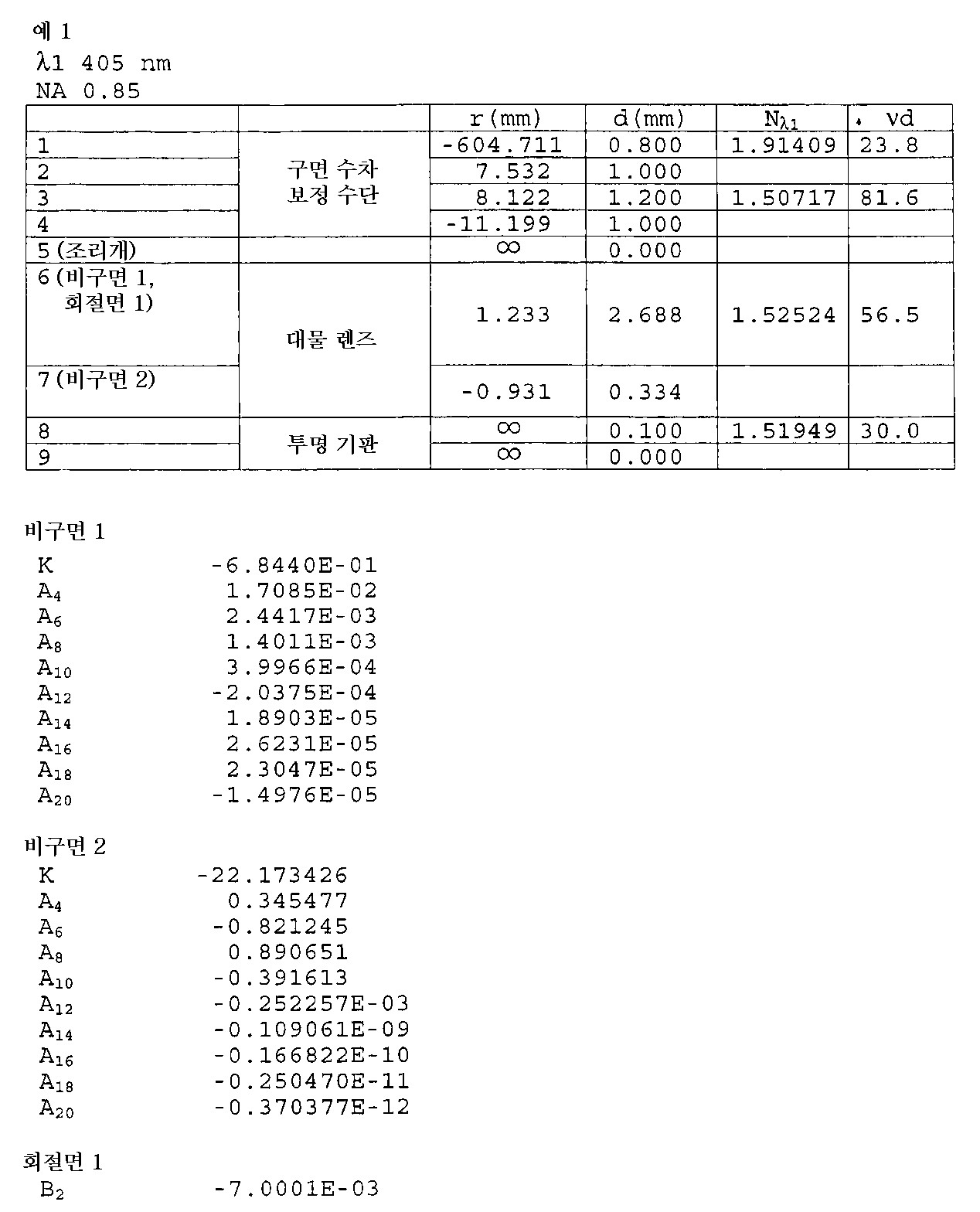
도2는 예1에 따른 오목 렌즈(5), 볼록 렌즈(4) 및 대물 렌즈(3)의 광학 시스템 구조도이다. 도3은 대물 렌즈(3)에 따른 구면 수차도이다. 예1에서, 정보는 파장 405nm 의 제1 광원(11) 및 대물 렌즈(3)의 상 측 개구수 NA 0.85의 조합에 의해 기록되거나 재생된다. 본 예에서, 구면 수차의 변이를 보정하기 위한 수단의 오목 렌즈(5) 및 볼록 렌즈(4)의 재료로서, vdN = 23.8, vdP = 81.6 의 재료가 각각 선택되고, 또한, 대물 렌즈(3)의 광원 측의 표면에 회절면을 제공함으로써, 대물 렌즈(3)에서 발생한 축 색 수차는 보정된다. 또한, 본 예에서, fN = -8.13 (mm), fP = 9.48 (mm), f = 1.765 (mm) 및 fD = 71.483 (mm) 이다.2 is an optical system structure diagram of the
본 예에서, 광원의 진동 파장의 미세한 변이(이하, 단순히 파장 변이라고 한다.) 및 온도 변화의 시점에서 구면 수차의 변이또는 온도 변화이 보정이 다음과 같이 수행될 수 있다. 본 예의 경우에, 대물 렌즈에서 파장이 길어지고, 온도가 상승할 때, 대물 렌즈(3)에서 과도 보정된 구면 수차가 발생된다. 이러한 경우, 오목 렌즈(5)는 액츄에이터(7)에 의해 광축을 따라 이동되고, 오목 렌즈(5) 와 볼록 렌즈(4) 사이의 간격은 줄어들고, 부족 보정된 구면 수차가 발생될 수 있다. 오목 렌즈(5)가 적당한 양만큼 이동될 때, 과도 보정된 구면 수차는 상쇄되고, 구면 수차의 결과를 보여지듯이 표2로부터 명백히 보여지고, 전체 광학 시스템의 구면 수차는 정밀하게 된다.In this example, correction of the minute variation of the oscillation wavelength of the light source (hereinafter simply referred to as wavelength variation) and the change of the spherical aberration or the temperature change at the time of the temperature change can be performed as follows. In the case of this example, when the wavelength becomes longer in the objective lens and the temperature rises, overcorrected spherical aberration is generated in the

주) 표 안의 괄호 안의 숫자는 구면 수차 보정 수단의 오목 렌즈와 볼록 렌즈 및 발산각 변화 수단 사이의 간격을 나타낸다.NOTE The numbers in parentheses in the table indicate the distance between the concave lens of the spherical aberration correction means, the convex lens and the divergence angle changing means.
[예 2][Example 2]
예2 에서 오목 렌즈(5), 볼록 렌즈(4) 및 대물 렌즈(3)로 구성된 광학 시스템에 관련된 데이터가 표3 에 보여진다. In Example 2, data relating to the optical system composed of the

도4는 예2 에 따른 오목 렌즈(5), 볼록 렌즈(4) 및 대물 렌즈(3)의 광학 시스템 구조도이다. 도5는 대물 렌즈(3)에 따른 구면 수차도이다. 예2 에서 정보는 파장 405 nm의 제1 광원(11) 및 대물 렌즈(3)의 상 측 개구수 NA 0.85의 조합에 의해 기록되거나 재생된다. 예2에서, 구면 수차의 변이를 보정하기 위한 수단의 오목 렌즈(5) 및 볼록 렌즈(4)의 재료로서 vdN = 30.0, vdP = 56.5 의 재료가 각각 선택되고, 또한, 대물 렌즈(3)의 광원 측의 표면에 회절면을 제공함으로써, 대물 렌즈(3)에서 발생한 축 색 수차는 보정된다. 또한, 본 예에서, fN = -4.75 (mm), fP = 6.47 (mm), f = 1.765 (mm) 및 fD = 71.483 (mm) 이다.4 is an optical system structure diagram of the
본 예의 파장 변이 또는 온도 변화의 시점에서 구면 수차의 변이의 보정이 예1 에서와 같기 때문에, 설명은 생략한다. 구면 수차의 보정 결과를 보여주는 표 4로부터 명백히 보여지듯이, 파장 변이 또는 온도 변화의 시점에서 구면 수차는 양호해진다. 또한, 대물 렌즈(3) 및 구면 수차의 변이의 보정을 위한 수단으로서, 플라스틱 재료가 오목 렌즈(5) 및 볼록 렌즈(4)를 위해 사용될 때, 광학 시스템의 무게 감소 및 이동 가능한 메커니즘 위의 부하 감소가 달성된다.Since the correction of the variation of the spherical aberration at the time of the wavelength variation or the temperature variation of this example is the same as in Example 1, the description is omitted. As is apparent from Table 4 showing the correction result of the spherical aberration, the spherical aberration becomes good at the time of the wavelength shift or the temperature change. Also, as a means for correcting the variation of the

주) 표 안의 괄호 안의 숫자는 구면 수차 보정 수단의 오목 렌즈와 볼록 렌즈 및 발산각 변화 수단 사이의 간격을 나타낸다.NOTE The numbers in parentheses in the table indicate the distance between the concave lens of the spherical aberration correction means, the convex lens and the divergence angle changing means.
[예 3]Example 3
예3에서 오목 렌즈(5), 볼록 렌즈(4) 및 대물 렌즈(3)으로 구성된 광학 시스템에 관련된 데이터가 표5에 보여진다. In Example 3, data relating to the optical system composed of the

도6은 예3에 따른 오목 렌즈(5), 볼록 렌즈(4) 및 대물 렌즈(3)의 광학 시스템 구조도이다. 도7는 대물 렌즈(3)에 따른 구면 수차도이다. 예3에서 정보는 파장 405nm 의 제1 광원(11) 및 대물 렌즈(3)의 상 측 개구수 NA 0.85의 조합에 의해 기록되거나 재생된다. 예3에서, 오목 렌즈(5) 및 볼록 렌즈(4)의 재료로서 vdN = 23.8, vdP = 81.6 의 재료를 각각 선택함으로써, 또한, 대물 렌즈(3)의 광원 측의 표면에 회절면을 제공함으로써, 축 색 수차는 보정된다. 또한, 본 예에서, fN = -9.27 (mm), fP = 11.08 (mm), f = 1.765 (mm)이다.6 is an optical system structure diagram of the
본 예의 파장 변이 또는 온도 변화의 시점에서 구면 수차의 변이의 보정이 예1에서와 같기 때문에, 설명은 생략한다. 구면 수차의 보정 결과를 보여주는 표 6으로부터 명백히 보여지듯이, 파장 변이 또는 온도 변화의 시점에서 구면 수차는 양호해진다. 또한, 플라스틱 재료가 대물 렌즈(3)에 사용될 때, 광학 시스템의 무게 감소 및 이동 가능한 메커니즘 위의 부하 감소가 달성된다. Since the correction of the variation of the spherical aberration at the time of the wavelength shift or the temperature change in this example is the same as in Example 1, the description is omitted. As is apparent from Table 6 showing the correction result of the spherical aberration, the spherical aberration becomes good at the point of wavelength shift or temperature change. In addition, when plastic material is used for the

주) 표 안의 괄호 안의 숫자는 구면 수차 보정 수단의 오목 렌즈와 볼록 렌즈 및 발산각 변화 수단 사이의 간격을 나타낸다.NOTE The numbers in parentheses in the table indicate the distance between the concave lens of the spherical aberration correction means, the convex lens and the divergence angle changing means.
[예 4]Example 4
예4에서 오목 렌즈(5), 볼록 렌즈(4) 및 대물 렌즈(3)으로 구성된 광학 시스템에 관련된 데이터가 표7에 보여진다. In Example 4, data relating to the optical system composed of the


도8 및 도9는 예4에 따른 오목 렌즈(5), 볼록 렌즈(4) 및 대물 렌즈(3)의 광학 시스템 구조도이다. 도10 및 도11은 정보가 다른 광학 정보 기록 매체를 위해 각각 기록되거나 재생될 때의 대물 렌즈(3)에 따른 구면 수차도이다. 예4는 동일한 광학 시스템을 사용하여 파장 405 nm의 제1 광원(11) 및 투명 기판의 두께가 0.6 mm인 광학 정보 기록 매체의 조합에 의해, 또는 파장 655 nm의 제2 광원(11) 및 투명 기판의 두께가 0.6 mm인 광학 정보 기록 매체의 조합에 의해 정보가 기록되거나 재생되는 광 픽업 장치의 예이다. 예4 에서, 오목 렌즈(5) 및 볼록 렌즈(4)의 재료로서 vdN = 30.0, vdP = 56.5의 재료를 각각 선택함으로써, 또한, 대물 렌즈(3)의 광원 측의 표면에 회절면을 제공함으로써, 축 색 수차는 보정된다. 또한, 본 예에서, fN = -3.82 (mm), fP = 6.85 (mm), f1 = 1.765 (mm) 및 fD1 = 5000000.02 (mm)이다. 이와 관련하여, 진동 파장이 λ2 = 655 nm 에서 대물 렌즈의 초점 거리는 f2 = 1.804 이다. 8 and 9 are optical system structural diagrams of the
예4 에서, 두가지 이상의 종류의 광학 정보 기록 매체에 투명 기판 두께의 차이로 인해 발생된 구면 수차의 변이는 광원 측으로부터 순서대로 하나의 오목 렌즈(5) 및 하나의 볼록 렌즈(4)로 구성되는 발산각 변화 수단(본 발명의 구면 수차의 변이를 보정하기 위한 수단 또는 구면 수차 및 축 색 수차의 변이를 보정하는 수단에 상응하는 수단)의 간격을 변화시킴으로써 보정된다. 또한, 대물 렌즈(3)의 광원 측 면 상에 회절면을 제공함으로써 구면 수차는 더욱 정밀하게 보정된다. 또한, 광원의 파장 변이 또는 온도 변화의 시점에서 수렴 광학 시스템의 구면 수차 편차는 발산각 변화 수단의 간격을 변화시킴으로써 정밀하게 보정된다. 그것은, 표8로부터 명백하게 알 수 있듯이오목 렌즈(5)와 볼록 렌즈(4)의 간격을 적당한 간격으로 변화시킴으로써 면 두께 변화의 시간 또는 파장 변이 및 온도 변화의 시점에서 대물 렌즈(3)의 열화는 정밀하게 보정된다. 또한, 플라스틱 재료가 대물 렌즈(3), 오목 렌즈(5) 및 볼록 렌즈(4)에 사용될 때, 광학 시스템의 무게 감소 및 이동 가능한 메커니즘 위의 부하 감소가 달성된다. In Example 4, the variation of the spherical aberration caused by the difference in the thickness of the transparent substrate in two or more kinds of optical information recording media consists of one

주) 표 안의 괄호 안의 숫자는 구면 수차 보정 수단의 오목 렌즈와 볼록 렌즈 및 발산각 변화 수단 사이의 간격을 나타낸다.NOTE The numbers in parentheses in the table indicate the distance between the concave lens of the spherical aberration correction means, the convex lens and the divergence angle changing means.
[예 5]Example 5
예5에서 오목 렌즈(5), 볼록 렌즈(4) 및 대물 렌즈(3)로 구성된 광학 시스템에 관련된 데이터가 표9에 보여진다. In Example 5, data relating to the optical system composed of the


도12 및 도13은 예5에 따른 오목 렌즈(5), 볼록 렌즈(4) 및 대물 렌즈(3)의 광학 시스템 구조도이다. 도14 및 도15는 정보가 다른 광학 정보 기록 매체를 위해 각각 기록되거나 재생될 때 대물 렌즈(3)에 따른 구면 수차도이다. 예5는 동일한 광학 시스템을 사용하여 파장 405 nm의 제1 광원(11) 및 투명 기판의 두께가 0.6 mm인 광학 정보 기록 매체의 조합에 의해, 또는 파장 655 nm의 제2 광원(11) 및 투명 기판의 두께가 0.6 mm인 광학 정보 기록 매체의 조합에 의해 정보가 기록되거나 재생되는 광 픽업 장치의 예이다. 예5 에서, 오목 렌즈(5) 및 볼록 렌즈(4)의 재료로서 vdN = 30.0, vdP = 56.5의 재료를 각각 선택함으로써, 축 색 수차는 보정된다. 또한, 본 예에서, fN = -6.59 (mm), fP = 9.85 (mm), f1 = 3.011 (mm) 및 fD1= 849964.33 (mm)이다. 이와 관련하여, 진동 파장이 λ2 = 655 nm에서 대물 렌즈의 초점 거리는 f2 = 3.076 이다. 12 and 13 are optical system structural diagrams of the
예4 에서와 동일한 방식으로, 표10으로부터 명백하게 알 수 있듯이 오목 렌즈(5)와 볼록 렌즈(4) 사이의 간격을 적당한 간격으로 변화시킴으로써 기판 두께 변화의 시점 또는 파장 변이 및 온도 변화의 시점에서 대물 렌즈(3)의 열화는 정밀하게 보정된다. 또한, 플라스틱 재료가 대물 렌즈(3), 오목 렌즈(5) 및 볼록 렌즈(4)에 사용될 때, 광학 시스템의 무게 감소 및 이동 가능한 메커니즘 위의 부하 감소가 달성된다.In the same manner as in Example 4, as apparent from Table 10, by changing the interval between the

주) 표 안의 괄호 안의 숫자는 구면 수차 보정 수단의 오목 렌즈와 볼록 렌즈및 발산각 변화 수단 사이의 간격을 나타낸다. NOTE The numbers in parentheses in the table indicate the distance between the concave lens of the spherical aberration correction means, the convex lens and the divergence angle changing means.
이와 관련하여, 구면 수차의 변이를 보정하기 위한 수단의 오목 렌즈(5)에 투사되는 광 플럭스가 평행 광일 뿐만 아니라 발산 광 또는 수렴 광일 때 조차, 본 발명의 광학 시스템은 동일한 방법으로 적용될 수 있다. 또한, 본 발명의 도면에는 도시되지 않았지만 광원으로부터 나온 광 플럭스의 발산각을 변화시키는 커플링 렌즈가 광원과 구면 수차 보정 수단 사이에 제공될 수 있다. 회절면이 그러한 커플링 렌즈에 추가될 때 그리고 회절면이 후방 초점이 긴 파장 측에서 짧아지는 특징을 가질 때, 대물 렌즈에서 발생한 축 색 수차는 보정될 수 있다.In this regard, even when the light flux projected on the
본 발명에 따른 광학 시스템에 사용되는 커플링 렌즈는 상기 모드에만 제한되지 않고, 본 출원에 의한 일본 출원 번호 2000-060843에 기술된 커플링 렌즈일 때, 대물 렌즈(3)에서 발생한 축 색 수차가 더욱 정밀하게 보정될 수 있다.The coupling lens used in the optical system according to the present invention is not limited to the above mode, and when the coupling lens described in Japanese application No. 2000-060843 according to the present application, the axial chromatic aberration generated in the
또한, 광원으로부터 광 플럭스의 비점 수차를 경감시키고 거의 원형인 광 플럭스를 구면 수차 보정 수단에 투사시킬 수 있는 빔 형성 요소가 커플링 렌즈와 구면 수차의 변이 보정 수단[오목 렌즈(4), 볼록 렌즈(5)] 사이에 제공될 때, 커플링 렌즈로부터 나온 광 플럭스의 발산각이 온도 또는 습도 변화에 기인한 초점 위치 이동에 의해 변하고 비점 수차는 빔 형성 요소에 의해 발생된다. 이것을 억제하기 위해, 일본 출원 번호 2000-053858에 기재된 커플링 렌즈가 사용될 때, 빔 모양 요소에 의한 비점 수차의 생성은 억제된다.Further, a beam forming element capable of reducing the astigmatism of the light flux from the light source and projecting a substantially circular light flux to the spherical aberration correcting means includes a displacement correction means of the coupling lens and the spherical aberration (
이와 관련하여, 예4 및 예5에서 광원 파장 655 nm이고, 투명 기판 두께가 0.6 mm 인 광학 정보 기록 매체에 대한 구면 수차도 NA 0.65 까지 보여진다. 그러나, 이 경우에, 광원 파장 405 mm, NA 0.85 에 의해 결정된 조리개 모두를 통과하는 광 플럭스는 대물 렌즈(3)에 투사된다. 상 정보에 기여하지 않는 NA 0.65 초과인 광 플럭스는 대물 렌즈(3)에 제공된 회절면의 효과를 이용함으로써 플레어 성분(flare component)으로 되고 따라서 스폿 직경은 광학 정보 기록면 상에서 과도하게 압착되지 않고 광 픽업 장치의 광 수용 요소 상의 불필요한 신호의 검출은 방지된다.In this regard, the spherical aberration for the optical information recording medium with the light source wavelength 655 nm and the transparent substrate thickness 0.6 mm in Examples 4 and 5 is also shown up to NA 0.65. However, in this case, the light flux passing through all of the apertures determined by the light source wavelength 405 mm and NA 0.85 is projected onto the
[예 6]Example 6
예6에서 오목 렌즈(5), 볼록 렌즈(4) 및 대물 렌즈(3)로 구성된 광학 시스템에 관련된 데이터가 표11 에 보여진다. In Example 6, data relating to the optical system composed of the


도16은 예6에 따른 오목 렌즈(5), 볼록 렌즈(4) 및 대물 렌즈(3)의 광학 시스템 구조도이다. 도17는 대물 렌즈(3)에 따른 구면 수차도이다. 예6에서 정보는 파장 405nm 의 제1 광원(11) 및 대물 렌즈(3)의 상 측 개구수 NA 0.85의 조합에 의해 기록되거나 재생된다. 예6에서, 회절면이 대물 렌즈(4)의 광학 정보 기록 매체 측의 표면에 추가될 때 그리고 회절 구조가 긴 파장 측에서 후방 초점 거리가 짧아지는 특징을 가질 때, 대물 렌즈(3)에서 발생한 축 색 수차는 보정된다. 또한, 본 예에서, fN = -0.503 (mm), fP = 6.81 (mm), f1 = 1.765 (mm)이다. 16 is an optical system structure diagram of the
본 예에서 파장 변이 또는 온도 변화의 시점에서 구면 수차의 변이의 보정이 예1에서와 같기 때문에, 설명은 생략한다. 표 12로부터 명백히 보여지듯이, 파장 변이 또는 온도 변화의 시점에서 구면 수차는 양호해진다. 또한, 플라스틱 재료가 대물 렌즈(3), 오목 렌즈(5) 및 볼록 렌즈(4)에 사용될 때, 광학 시스템의 무게 감소 및 이동 가능한 메커니즘 위의 부하 감소가 달성된다.In this example, since the correction of the variation of the spherical aberration at the time of the wavelength shift or the temperature change is the same as in Example 1, the description is omitted. As is apparent from Table 12, the spherical aberration becomes good at the time of the wavelength shift or the temperature change. In addition, when plastic material is used for the

주) 표 안의 괄호 안의 숫자는 구면 수차 보정 수단의 오목 렌즈와 볼록 렌즈 및 발산각 변화 수단 사이의 간격을 나타낸다. NOTE The numbers in parentheses in the table indicate the distance between the concave lens of the spherical aberration correction means, the convex lens and the divergence angle changing means.
[예 7]Example 7
*예7 에서 오목 렌즈(5), 볼록 렌즈(4) 및 대물 렌즈(3)로 구성된 광학 시스템에 관련된 데이터가 표13에서 보여진다. In Example 7, data relating to the optical system composed of the


도18은 예7에 따른 오목 렌즈(5), 볼록 렌즈(4) 및 대물 렌즈(3)의 광학 시스템 구조도이다. 도19는 대물 렌즈(3)에 따른 구면 수차도이다. 예7에서 정보는 파장 405 nm의 제1 광원(11) 및 대물 렌즈(3)의 상 측 개구수 NA 0.85의 조합에 의해 기록되거나 재생된다. 예7에서, 회절면이 오목 렌즈(5) 및 볼록 렌즈(4)의 양 표면에 추가될 때 그리고 회절 구조가 긴 파장 측에서 후방 초점 거리가 짧아지는 특징을 가질 때, 대물 렌즈(3)에서 발생한 축 색 수차는 보정된다. 또한, 본 예에서, fN = -4.89 (mm), fP = 5.83 (mm), f1 = 1.765 (mm)이다.18 is an optical system structure diagram of the
본 예의 파장 변이 또는 온도 변화의 시점에서 구면 수차의 변이의 보정이 예1에서와 같기 때문에, 설명은 생략한다. 표 14로부터 명백히 보여지듯이, 파장 변이 또는 온도 변화의 시점에서 구면 수차는 양호해진다. 또한, 플라스틱 재료가 대물 렌즈(3), 오목 렌즈(5) 및 볼록 렌즈(4)에 사용될 때, 광학 시스템의 무게 감소 및 이동 가능한 메커니즘위의 부하 감소가 달성된다.Since the correction of the variation of the spherical aberration at the time of the wavelength shift or the temperature change in this example is the same as in Example 1, the description is omitted. As is apparent from Table 14, the spherical aberration becomes good at the time of the wavelength shift or the temperature change. In addition, when plastic material is used for the

주) 표 안의 괄호 안의 숫자는 구면 수차 보정 수단의 오목 렌즈와 볼록 렌즈 및 발산각 변화 수단 사이의 간격을 나타낸다. NOTE The numbers in parentheses in the table indicate the distance between the concave lens of the spherical aberration correction means, the convex lens and the divergence angle changing means.
[예 8]Example 8
예8에서 오목 렌즈(5), 볼록 렌즈(4) 및 대물 렌즈(3)로 구성된 광학 시스템에 관련된 데이터가 표15에서 보여진다. In Example 8, data relating to an optical system composed of a


도20은 예8에 따른 오목 렌즈(5), 볼록 렌즈(4) 및 대물 렌즈(3)의 광학 시스템 구조도이다. 도21는 대물 렌즈(3)에 따른 구면 수차도이다. 예8에서 정보는 파장 405 nm의 제1 광원(11) 및 대물 렌즈(3)의 상 측 개구수 NA 0.85의 조합에 의해 기록되거나 재생된다. 예8에서, 회절면이 오목 렌즈(5) 및 볼록 렌즈(4)의 양 표면에 추가될 때 그리고 회절 구조가 긴 파장 측에서 후방 초점 거리가 짧아지는 특징을 가질 때, 대물 렌즈(3)에서 발생한 축 색 수차는 보정된다. 또한, 본 예에서, fN = -5.54 (mm), fP = 7.42 (mm), f1 = 1.765 (mm)이다.20 is an optical system structure diagram of the
본 예의 파장 변이 또는 온도 변화의 시점에서 구면 수차의 변이의 보정이 예1에서와 같기 때문에, 설명은 생략한다. 표 16으로부터 명백히 보여지듯이, 파장 변이 또는 온도 변화의 시점에서 구면 수차는 양호해진다. 또한, 플라스틱 재료가 대물 렌즈(3), 오목 렌즈(5) 및 볼록 렌즈(4)에 사용될 때, 광학 시스템의 무게 감소 및 이동 가능한 메커니즘 위의 부하 감소가 달성된다.Since the correction of the variation of the spherical aberration at the time of the wavelength shift or the temperature change in this example is the same as in Example 1, the description is omitted. As is apparent from Table 16, the spherical aberration becomes good at the time of the wavelength shift or the temperature change. In addition, when plastic material is used for the

주) 표 안의 괄호 안의 숫자는 구면 수차 보정 수단의 오목 렌즈와 볼록 렌즈 및 발산각 변화 수단 사이의 간격을 나타낸다. NOTE The numbers in parentheses in the table indicate the distance between the concave lens of the spherical aberration correction means, the convex lens and the divergence angle changing means.
[예 9]Example 9
*예9에서 오목 렌즈(5), 볼록 렌즈(4) 및 대물 렌즈(3)으로 구성된 광학 시스템에 관련된 데이터가 표17에서 보여진다.In Example 9, data relating to the optical system composed of the


도22는 예9에 따른 오목 렌즈(5), 볼록 렌즈(4) 및 대물 렌즈(3)의 광학 시스템 구조도이다. 도23는 대물 렌즈(3)에 따른 구면 수차도이다. 예9에서 정보는 파장 405 nm의 제1 광원(11) 및 대물 렌즈(3)의 상 측 개구수 NA 0.85의 조합에 의해 기록되거나 재생된다. 예8에서, 회절면이 오목 렌즈(5) 및 볼록 렌즈(4)의 양 표면에 추가될 때 그리고 회절 구조가 긴 파장 측에서 후방 초점 거리가 짧아지는 특징을 가질 때, 대물 렌즈(3)에서 발생한 축 색 수차는 보정된다. 또한, 구면 수차 보정 수단의 오목 렌즈(5) 및 볼록 렌즈(4)의 재료로서 각각 N = 30.0 및 P = 56.5의 재료를 선택함으로써 대물 렌즈(3) 안의 축 색 수차는 더욱 정밀하게 보정된다. 또한, 본 예에서, fN = -4.15 (mm), fP = 5.91 (mm), f1 = 1.765 (mm)이다. 22 is an optical system structure diagram of the
본 예의 광원의 파장 변이 또는 온도 변화의 시점에서 구면 수차의 변이의 보정이 예1에서와 같기 때문에, 설명은 생략한다. 18로부터 명백히 보여지듯이, 파장 변이 또는 온도 변화의 시점에서 구면 수차는 양호해진다. 또한, 플라스틱 재료가 대물 렌즈(3), 오목 렌즈(5) 및 볼록 렌즈(4)에 사용될 때, 광학 시스템의 무게 감소 및 이동 가능한 메커니즘 위의 부하 감소가 달성된다.Since the correction of the variation of the spherical aberration at the time of the wavelength shift or the temperature change of the light source of this example is the same as in Example 1, the description is omitted. As is apparent from 18, spherical aberration becomes good at the point of wavelength shift or temperature change. In addition, when plastic material is used for the

주) 표 안의 괄호 안의 숫자는 구면 수차 보정 수단의 오목 렌즈와 볼록 렌즈 및 발산각 변화 수단 사이의 간격을 나타낸다. NOTE The numbers in parentheses in the table indicate the distance between the concave lens of the spherical aberration correction means, the convex lens and the divergence angle changing means.
[예 10][Example 10]
예10 에서 오목 렌즈(5), 볼록 렌즈(4) 및 대물 렌즈(3)로 구성된 광학 시스템에 관련된 데이터가 표19 에서 보여진다.In Example 10 data relating to an optical system consisting of


도24는 예10에 따른 오목 렌즈(5), 볼록 렌즈(4) 및 대물 렌즈(3)의 광학 시스템 구조도이다. 도25는 대물 렌즈(3)에 따른 구면 수차도이다. 예10에서 정보는 파장 405 nm의 제1 광원(11) 및 대물 렌즈(3)의 상 측 개구수 NA 0.85의 조합에 의해 기록되거나 재생된다. 예10에서, 회절면이 오목 렌즈(5) 및 볼록 렌즈(4)의 양 표면에 추가될 때 그리고 긴 파장 측에서 후방 초점 거리가 짧아지는 특징을 가질 때, 대물 렌즈(3)에서 발생한 축 색 수차는 보정된다. 이 경우에, 대물 렌즈(3), 오목 렌즈(5) 및 볼록 렌즈(4)가 구면 수차 보정 수단으로서 결합된 복합 시스템의 축 색 수차가 도 25에 도시된 바와 같이 부족 보정된 상태로 만들어 될 때, 제1 광원(11)의 진동 파장(405nm)의 구면 수차 곡선 및 장.단 파장 상의 구면 수차 곡선은 서로 교차하도록 된다. 따라서, 광원의 모드 홉핑이 일어날 때, 고 주파수 중첩의 시점에서 파면 수차의 저하는 아주 작아지고, 예를 들면, 광원의 진동 파장이 미세하게 변할 때, 최상의 상 면의 위치의 이동은 작게 억제된다. 또한, 구면 수차 보정 수단으로서 이동 가능한 요소인 오목 렌즈(5)가 비구면 렌즈의 양 측에 형성될 때, 오목 렌즈의 중심 이탈의 시점에서 파면 수차의 열하 또는 트랙킹 오차는 작게 억제된다. 또한, 오목 렌즈(5) 및 볼록 렌즈(4)의 재료로서 vdN = 30.0, vdP = 56.5의 재료가 각각 선택됨으로써, 대물 렌즈(3)의 축 색 수차는 보정되고, 볼록 렌즈(4)에 추가된 회절 구조의 부하가 가벼워진다. 또한, 본 예에서, fN = -7.78 (mm), fP = 9.95 (mm), f1 = 1.765(mm)이다. 24 is an optical system structure diagram of the
본 예에서, 광 플럭스를 조정하기 위한 조리개가 대물 렌즈(3)의 광원 측의 표면의 꼭대기로부터 광학 정보 기록 매체측에 정렬되기 때문에, 발산 광 플럭스가 투사될 때, 대물 렌즈(3)의 최대 광원 측 상의 표면 높이를 지나는 광선은 작게 억제될 수 있다. 이것은 대물 렌즈(3)의 크기 축소 또는 수차 보정에도 바람직하다.In this example, since the aperture for adjusting the light flux is aligned from the top of the surface of the light source side of the
본 예의 광원의 파장 변이 또는 온도 변화의 시점에서 구면 수차의 변이의 보정이 예1에서와 같기 때문에, 설명은 생략한다. 표 20으로부터 명백히 보여지듯이, 파장 변이 또는 온도 변화의 시점에서 구면 수차는 양호해진다. 또한, 플라스틱 재료가 대물 렌즈(3), 오목 렌즈(5) 및 볼록 렌즈(4)를 위해 사용될 때, 광학 시스템의 무게 감소 및 이동 가능한 메커니즘 위의 부하 감소가 달성된다. 또한, 짧은 파장의 광에 대한 내부 투과율이 높은 플라스틱 재료가 사용되기 때문에, 많은 양의 렌즈가 저 비용으로 생산될 수 있고, 광을 이용하는 고 효율의 광학 시스템이 실현된다. 이와 관련하여, 이동 가능한 메커니즘은 본 명세서의 예의 오목 렌즈(5)의 이동 메커니즘 및 대물 렌즈(3)의 포커싱 메커니즘이다. Since the correction of the variation of the spherical aberration at the time of the wavelength shift or the temperature change of the light source of this example is the same as in Example 1, the description is omitted. As is apparent from Table 20, the spherical aberration becomes good at the time of wavelength shift or temperature change. In addition, when plastic material is used for the

주) 표 안의 괄호 안의 숫자는 구면 수차 보정 수단의 오목 렌즈와 볼록 렌즈 및 발산각 변화 수단 사이의 간격을 나타낸다. NOTE The numbers in parentheses in the table indicate the distance between the concave lens of the spherical aberration correction means, the convex lens and the divergence angle changing means.
이와 관련하여, 본 예에서, 도25에는 도시되지 않았지만, 도1의 실시예에 도시된 대로, 실용적 광 픽업 장치에는 콜리메이터와 같은 커플링 렌즈가 광원과 구면 수차 보정 수단 사이에 제공된다. 이 경우에, 또한 커플링 렌즈에서 발생된 축 색 수차는 본 예의 구조에 의해 보정될 수 있고, 양호한 색 수차의 수렴 광학 시스템을 얻을 수 있다. In this regard, in this example, although not shown in Fig. 25, as shown in the embodiment of Fig. 1, a practical optical pickup device is provided with a coupling lens such as a collimator between the light source and the spherical aberration correcting means. In this case, the axial chromatic aberration generated in the coupling lens can also be corrected by the structure of the present example, and a converging optical system of good chromatic aberration can be obtained.
또한, 소위 2층 기록 시스템 광학 정보 기록 매체는 공지되어 있는데 광학 정보 기록 매체의 일 측 상에 제1 정보 기록 층 및 제2 정보 기록 층을 위한 2 상 변화 층을 제공함으로써 그리고 그 각각에 정보를 기록함으로써, 광학 정보 기록 매체의 저장 용량은 약 2배로 증가한다. 그러나 본 예의 장치는 그러한 2층 기록 시스템 광학 정보 기록 매체에서 정보의 기록 또는 재생을 위해 적용될 수 있고, 광 플럭스의 투사면과 각 정보 기록 층의 정보 기록면 사이의 두께 차이로 인해 발생된 구면 수차는 보정될 수 있다. 예를 들면, 구면 수차 보정 수단으로서의 오목 렌즈(5)와 볼록 렌즈(4) 사이의 간격을 축소함으로써 도26에 도시된 바와 같이 제1 정보 기록 층 및 제2 정보 기록 층이 광학 정보 기록 매체의 광 플럭스의 투사면으로부터 순서대로 정의될 때, 정보의 기록 또는 재생은 제2 정보 기록 층의 정보 기록면 상에서 수행될 수 있다. In addition, so-called two-layer recording system optical information recording media are known which provide information on and on each of them by providing a two-phase change layer for the first information recording layer and the second information recording layer on one side of the optical information recording medium. By recording, the storage capacity of the optical information recording medium is about doubled. However, the apparatus of this example can be applied for recording or reproducing information in such a two-layer recording system optical information recording medium, and the spherical aberration caused by the thickness difference between the projection surface of the optical flux and the information recording surface of each information recording layer is Can be corrected. For example, by reducing the interval between the
[예 11]Example 11
예11에서 오목 렌즈(5), 볼록 렌즈(4) 및 대물 렌즈(3)으로 구성된 광학 시스템에 관련된 데이터가 표21에 보여진다.In Example 11, data relating to the optical system composed of the


도27은 예9에 따른 오목 렌즈(5), 볼록 렌즈(4) 및 대물 렌즈(3)의 광학 시스템 구조도이다. 도28은 대물 렌즈(3)에 따른 구면 수차도이다. 예11에서 정보는 파장 405 nm의 제1 광원(11) 및 대물 렌즈(3)의 상 측 개구수 NA 0.85의 조합에 의해 기록되거나 재생된다. 예11에서, 회절면이 오목 렌즈(5) 및 볼록 렌즈(4)의 양 표면에 추가될 때 그리고 긴 파장 측에서 후방 초점 거리가 짧아지는 특징을 가지질 때, 대물 렌즈(3)에서 발생한 축 색 수차는 보정된다. 또한, 구면 수차 보정 수단으로서의 이동 가능한 요소인 오목 렌즈(5)가 양쪽 비구면 렌즈일 때, 오목 렌즈의 중심 이탈의 시점에서 파면 수차의 열하 또는 트랙킹 오차는 작게 억제된다. 또한, 본 예에서, fN = -8.32 (mm), fP = 12.30 (mm), f1 = 1.765 (mm), fD = 28.417 (mm)이다.27 is an optical system structure diagram of the
본 예의 광원의 파장 변이 또는 온도 변화의 시점에서 구면 수차의 변이의 보정이 예1에서와 같기 때문에, 설명은 생략한다. 표 22로부터 명백히 보여지듯이, 파장 변이 또는 온도 변화의 시점에서 구면 수차는 양호해진다. 또한, 플라스틱 재료가 대물 렌즈(3), 오목 렌즈(5) 및 볼록 렌즈(4)에 사용될 때, 광학 시스템의 무게 감소 및 이동 가능한 메커니즘 위의 부하 감소가 달성된다. 또한, 단 파장 광에 대해 내부 투과율이 높은 플라스틱 재료가 사용되기 때문에, 다량의 렌즈가 저 비용으로 생산될 수 있고, 광을 이용하는 고 효율의 광학 시스템이 얻어진다.Since the correction of the variation of the spherical aberration at the time of the wavelength shift or the temperature change of the light source of this example is the same as in Example 1, the description is omitted. As is apparent from Table 22, the spherical aberration becomes good at the time of the wavelength shift or the temperature change. In addition, when plastic material is used for the

주) 표 안의 괄호 안의 숫자는 구면 수차 보정 수단의 오목 렌즈와 볼록 렌즈 및 발산각 변화 수단 사이의 간격을 나타낸다. NOTE The numbers in parentheses in the table indicate the distance between the concave lens of the spherical aberration correction means, the convex lens and the divergence angle changing means.
[예 12]Example 12
예12 에서 오목 렌즈(5), 볼록 렌즈(4) 및 대물 렌즈(3)으로 구성된 광학 시스템에 관련된 데이터가 표23 에서 보여진다.In Example 12 the data relating to the optical system consisting of the


도29 및 30은 예12에 따른 오목 렌즈(5), 볼록 렌즈(4) 및 대물 렌즈(3)의 광학 시스템 구조도이다. 도31 및 도32는 정보가 다른 광 정보 매체에 대해 각각 기록되거나 재생될 때, 대물 렌즈(3)에 따른 구면 수차도이다. 예12는 파장 405 nm인 제1 광원(11) 및 투명 기판의 두께가 0.1 mm인 광학 정보 기록 매체의 조합에 의해 또는 파장 655 nm인 제2 광원(11) 및 투명 기판의 두께가 0.1 mm인 광학 정보 기록 매체의 조합에 의해 정보가 기록 또는 재생되는 광 픽업 장치의 예이다. 예12에서, 회절면이 대물 렌즈(3)의 광원 측의 표면에 추가될 때, 투명 기판의 두께의 차이로 인해 발생된 구면 수차 및 색의 구면 수차는 보정된다. 특히, 그것은 대물 렌즈(3)에 투사되는 광 플럭스의 주변 광선의 경사각이 정보 기록 매체의 투명 기판 두께에 대응하여 변할 때, 구면 수차 보정 수단으로서의 오목 렌즈(5)를 광축 방향으로 이동시킴으로써 수행된다. 또한, 본 예에서, fN = -6.39 (mm), fP = 10.51 (mm), f1 = 1.765 (mm), fD1 = 45.46 (mm)이다. 이와 관련하여, 진동 파장 λ2 = 655nm 에서, 대물 렌즈의 초점 거리는 f2 = 1.79 이다.29 and 30 are optical system structural diagrams of the
본 예의 광원의 파장 변이 또는 온도 변화의 시점에서 구면 수차의 변이의 보정이 예1에서와 같기 때문에, 설명은 생략한다. 표 24로부터 명백히 보여지듯이, 파장 변이 또는 온도 변화의 시점에서 구면 수차는 양호해진다. 또한, 플라스틱 재료가 대물 렌즈(3), 오목 렌즈(5) 및 볼록 렌즈(4)를 위해 사용될 때, 광학 시스템의 무게 감소 및 이동 가능한 메커니즘 위의 부하 감소가 달성된다. 또한, 단 파장에 대해 내부 투과율이 높은 플라스틱 재료가 사용되기 때문에, 다량의 렌즈가 저 비용으로 생산될 수 있고, 광을 이용하는 고 효율의 광학 시스템이 얻어진다.Since the correction of the variation of the spherical aberration at the time of the wavelength shift or the temperature change of the light source of this example is the same as in Example 1, the description is omitted. As is apparent from Table 24, the spherical aberration becomes good at the time of wavelength shift or temperature change. In addition, when plastic material is used for the

주) 표 안의 괄호 안의 숫자는 구면 수차 보정 수단의 오목 렌즈와 볼록 렌즈 및 발산각 변화 수단 사이의 간격을 나타낸다. NOTE The numbers in parentheses in the table indicate the distance between the concave lens of the spherical aberration correction means, the convex lens and the divergence angle changing means.
이와 관련하여, 예4 및 예5에서와 같은 방식으로, 광원 파장 655 nm이고 투명 기판 두께가 0.6 mm인 광학 정보 기록 매체에 대해 NA 0.65 보다 큰 광 플럭스가 대물 렌즈(3)에 제공된 회절면의 효과를 이용해 플레어 성분으로 될 때, 스폿 직경은 광학 정보 기록면 상에서 과도하게 압착되지 않고 광 픽업 장치의 광 수용 요소 상의 불필요한 신호의 검출은 방지된다.In this regard, in the same manner as in Examples 4 and 5, for an optical information recording medium having a light source wavelength of 655 nm and a transparent substrate thickness of 0.6 mm, an optical flux larger than NA 0.65 is applied to the diffractive surface provided in the
[예 13]Example 13
예13에서 커플링 렌즈(21) 또는 커플링 렌즈(15, 21)에 상응하는 콜리메이터, 오목 렌즈(5), 볼록 렌즈(4) 및 대물 렌즈(3)으로 구성된 광학 시스템에 관련된 데이터가 표25에서 보여진다.In Example 13, data relating to an optical system consisting of a collimator, a


도33은 예13에 따른 콜리메이터, 오목 렌즈(5), 볼록 렌즈(4) 및 대물 렌즈(3)의 광학 시스템 구조도이다. 도34는 대물 렌즈(3)에 따른 구면 수차도이다. 예13에서 정보는 파장 405 nm인 제1 광원(11) 및 대물 렌즈(3)의 상 측 개구수 NA 0.85의 조합에 의해 기록 또는 재생된다. 예13에서, 구면 수차 보정 수단의 오목 렌즈(5)를 광축 방향으로 이동시킴으로써 대물 렌즈(3)에 투사되는 광 플럭스의 주변 광선의 경사각이 변하고, 수렴 광학 시스템[콜리메이터 및 대물 렌즈(3)]의 각 광학 면에서 발생한 구면 수차의 변이는 보정된다. 또한, 본 예에서, fN = -10.71 (mm), fP = 13.18 (mm), f1 = 1.765 (mm)이다. 33 is an optical system structural diagram of a collimator, a
또한, 회절면은 볼록 렌즈(4)의 양 면에 추가되고, 수렴 광학 시스템의 광학 면에 의해 발생한 축 색 수차의 부호에 대해 반대 부호를 가지는 축 색 수차는 구면 수차 보정 수단 그 자체 안에서 발생되고, 따라서, 수렴 광학 시스템의 광학 면에 의해 발생된 축 색 수차는 보정되고, 초점이 정보 기록면에 형성될 때 파면의 축 색 수차는 정밀하게 된다. 본 예의 수렴 광학 시스템에서, 콜리메이터 및 대물 렌즈(3)에 의해 발생된 축 색 수차가 각각 ΔfB1, ΔfB2이고, 그들의 비가 대략 알려질 때, 콜리메이터의 초점 거리가 12 mm이기 때문에 구면 수차 보정 수단의 배율은 1.23 배이고, 대물 렌즈의 초점 거리는 1.765 mm이고, ΔfB1/ΔfB2 는 1/30이다. 즉, 구면 수차 보정 수단에 의해 발생된 축 색 수차의 절대 값이 거의 대물 렌즈에 의해 발생된 축 색 수차의 절대 값과 동일한 값일 때, 초점이 정보 기록면에 형성된 경우 파면의 축 색 수차는 정밀하게 된다. 그 시점에서 수렴 광학 시스템, 오목 렌즈(5) 및 볼록 렌즈(4)가 구면 수차 보정 수단으로서 결합한 복합 시스템의 축 색 수차가, 과도 보정된 상태로 보정될 때, 도34에 도시된 바와 같이 제1 광원(11)의 진동 파장(405 nm)의 구면 수차 곡선 및 장.단 파장 측의 구면 수차 곡선은 서로 교차된다. 따라서, 광원의 모드 홉 현상 또는 고 주파수 중첩의 시점에서 파면 수차의 열하가 작을때 조차도, 예를 들면 광원의 진동 파장이 미세하게 변할 때, 최상의 상 면의 위치의 이동은 작게 억제된다. 또한, 구면 수차 보정 수단의 이동 가능한 요소인 오목 렌즈(5)가 쌍 비구면 렌즈(biaspherical)일 때, 트랙킹 오차의 시점에서 오목 렌즈의 중심 이탈 또는 파면 수차의 열하는 작게 억제된다. Further, the diffractive surface is added to both sides of the
표26으로부터 명백히 알 수 있듯이, 파장 변이의 시간 또는 온도 변화의 시점에서와 같은 여러가지 요소에 의해 수렴 광학 시스템의 각각의 광학 면에 발생된 구면 수차의 변이는 보정될 수 있고, 구면 수차는 양호해 진다. 또한 플라스틱 재료가 구면 수차 보정 수단을 구성하는 콜리메이터, 대물 렌즈(3), 오목 렌즈(5) 및 볼록 렌즈(4) 모두에 사용될 때, 광학 시스템의 무게 감소 및 이동 가능한 메커니즘 위의 부하 감소가 달성될 수 있다. 또한, 단 파장에 대해 내부 투과율이 높은 플라스틱 재료가 사용되기 때문에, 다량의 렌즈가 저 비용으로 생산될 수 있고, 광을 이용하는 고 효율의 광학 시스템이 얻어진다.As is apparent from Table 26, the variation of spherical aberration generated in each optical plane of the converging optical system can be corrected by various factors such as the time of wavelength shift or the point of temperature change, and the spherical aberration is good. Lose. In addition, when the plastic material is used in both the collimator, the

주) 온도 변화시 광원의 진동 파장 변화량 Δλ =+0.05 nm/°C .Note) The change in vibration wavelength of the light source at temperature changes Δλ = +0.05 nm / ° C.
이와 관련하여, 본 예에서, 구면 수차 보정 수단 안의 오목 렌즈(5)는 이동 가능하게 만들어지나, 볼록 렌즈(4)는 이동 가능하게 만들어 질 수도 있고, 또한, 같은 방법으로 양 렌즈 모두가 이동 가능하게 만들어질 때, 수렴 광학 시스템의 구면 수차의 변이는 보정될 수 있다. 또한, 본 예에서, 수렴 광학 시스템의 축 색 수차 및 구면 수차 보정 수단이 구면 수차 보정 수단의 볼록 렌즈(4)에 제공된 회절 구조에 의해 보정되더라도, 회절 구조는 또한 다른 렌즈의 표면에 제공될 수 있거나, 회절 구조가 제공된 표면을 가지는 광 요소가 다른 부분에 별도로 추가될 수도 있다.In this regard, in this example, the
[예 14] Example 14
예14에서 커플링 렌즈(15), 오목 렌즈(5), 볼록 렌즈(4) 및 대물 렌즈(3)로 구성된 광학 시스템에 관련된 데이터가 표27에서 보여진다.In Example 14 data relating to an optical system consisting of


도35는 예14에 따른 커플링 렌즈(15), 오목 렌즈(5), 볼록 렌즈(4) 및 대물 렌즈(3)의 광학 시스템 구조도이다. 커플링 렌즈(15)는 제1 광원으로부터 나온 강한 발산 광을 약한 발산 광으로 전환시키는 기능이 있다. 도36는 대물 렌즈(3)에 따른 구면 수차도이다. 예14에서 정보는 파장 405 nm인 제1 광원(11) 및 대물 렌즈(3)의 상 측 개구수 NA 0.85의 조합에 의해 기록 또는 재생된다. 예14에서, 구면 수차 보정 수단으로서 오목 렌즈(5)를 광축 방향을 따라 이동시킴으로써 대물 렌즈(3)에 투사되는 광 플럭스의 주변 광선의 경사각이 변하고, 수렴 광학 시스템[커플링 렌즈(15) 및 대물 렌즈(3)]의 각 광 면에서 발생한 구면 수차의 변이는 보정된다. 또한, 본 예에서, fN = -14.67 (mm), fP = 11.66 (mm) 및 f1 = 1.765 (mm)이다. 35 is an optical system structure diagram of the
또한, 회절면은 볼록 렌즈(4)의 양 면에 추가되고, 수렴 광학 시스템의 광 면에 의해 발생한 축 색 수차의 부호에 대해 반대 부호를 가지는 축 색 수차는 구면 수차 보정 수단 그 자체 안에서 발생되고, 따라서, 수렴 광학 시스템의 광학 면에 의해 발생된 축 색 수차는 보정되며, 초점이 정보 기록면에 형성되는 파면의 축 색 수차는 정밀하게 만들어진다. 구면 수차 보정 수단으로서 수렴 광학 시스템, 오목 렌즈(5) 및 볼록 렌즈(4)가 결합한 복합 시스템의 축 색 수차가, 도36 에 도시된 바와 같이 과도 보정된 상태로 보정될 때, 제1 광원(11)의 진동 파장(405nm)의 구면 수차 곡선 및 장.단 파장 측의 구면 수차 곡선은 서로 교차된다. 따라서, 광원의 모드 홉 현상 또는 고 주파수 중첩시에 파면 수차의 저하가 매우 작을 때, 예를 들면 광원의 진동 파장이 미세하게 변할 때 조차도, 최상의 상 면의 위치 이동은 작게 억제될 수 있다. Further, the diffractive surface is added to both sides of the
표28로부터 명백히 알 수 있듯이, 파장 변이 또는 온도 변화시와 같은 여러가지 요소로 인해 수렴 광학 시스템의 각각의 광 면에 발생된 구면 수차의 변이는 보정될 수 있고, 구면 수차는 양호해 진다. 또한, 플라스틱 재료가 구면 수차 보정 수단을 구성하는 커플링 렌즈(15), 대물 렌즈(3), 오목 렌즈(3) 및 볼록 렌즈(4)의 모두에 대해 사용될 때, 광학 시스템의 무게 감소 및 이동 가능한 메커니즘 위의 부하 감소가 달성된다. 또한, 단 파장 광에 대해 투과율이 높은 플라스틱 재료가 사용되기 때문에, 다량의 렌즈가 저 비용으로 생산될 수 있고, 광을 이용하는 고 효율의 광학 시스템이 얻어진다. 또한, 본 예에서, 구면 수차 보정 수단에 대한 투사 광이 약 발산 광 플럭스이기 때문에, 구면 수차 보정 수단에서 커플링 렌즈(15)의 배율 및 오목 렌즈(5)의 배율은 작아질 수 있고, 각각의 렌즈의 편심으로 인한 파면 수차의 저하는 작게 억제될 수 있다.As is apparent from Table 28, variations in spherical aberration generated in each light plane of the converging optical system due to various factors such as wavelength shift or temperature change can be corrected, and spherical aberration becomes good. In addition, when the plastic material is used for all of the

주) 온도 변화시 광원의 진동 파장 변화량 Δλ =+0.05 nm/°C .Note) The change in vibration wavelength of the light source at temperature changes Δλ = +0.05 nm / ° C.
이와 관련하여, 본 예에서, 구면 수차 보정 수단에서 오목 렌즈(5)는 이동 할 수 있게 만들어지지만, 볼록 렌즈(4)도 이동 가능하게 만들어 질 수 있고, 또한, 같은 방법으로 양 렌즈 모두가 이동 가능하게 만들어질 때, 수렴 광학 시스템의 구면 수차의 변이는 보정될 수 있다. 또한, 본 예에서, 수렴 광학 시스템의 축 색 수차 및 구면 수차 보정 수단이 구면 수차 보정 수단의 볼록 렌즈(4)에 제공된 회절면에 의해 보정되더라도, 회절면은 다른 렌즈의 면에 제공될 수 있거나, 이와 달리 회절 구조가 제공 되는 면을 가지는 광학 요소가 각각 시스템에 별도로 추가될 수도 있다.In this regard, in this example, in the spherical aberration correcting means, the
상기에 기술된 각각의 예에서, 구면 수차 보정 수단으로서, 빔 확장기가 사용되고, 빔 확장기로서, 이동 가능한 단일의 오목 렌즈 및 단일의 볼록 렌즈에 의해 구성된 예가 보여짐에도 불구하고, 확장기는 물론 그에 제한되지 않으며, 다수의 렌즈로 구성된 둘 또는 그 이상의 렌즈 그룹으로 구성된 구조가 될 수 있으며, 본 발명의 정신으로부터 이탈하지 않는 한 다양한 수정이 가능하다.In each of the examples described above, although a beam expander is used as the spherical aberration correcting means, and an example constituted by a single concave lens and a single convex lens movable as the beam expander is shown, the expander is not limited thereto, of course. It may be a structure composed of two or more lens groups composed of a plurality of lenses, and various modifications are possible without departing from the spirit of the present invention.
도37은 다른 실시예를 따르는 광학 시스템을 도시한 도이다. 구면 수차의 변이를 보정하기 위한 요소(SE)가 삽입된다. 그러한 광학 시스템은 도1의 오목 렌즈(5), 볼록 렌즈(4) 및 대물 렌즈(3)를 교체함으로써 사용될 수 있다. 37 illustrates an optical system according to another embodiment. An element SE for correcting the variation of spherical aberration is inserted. Such an optical system can be used by replacing the
요소(SE)는 X방향 액체 결정 요소(SE1), 1/2 파장 판(SE2) 및 Y방향 액체 결정 요소(SE3)가 각각 커플링 렌즈(CL) 측으로부터 4개의 유리 판(SE4)을 사이에 두고 끼워지는 것으로 구성된다. 양 유체 결정 요소(SE1, SE2)를 전기적으로 구동함으로써, 구면 수차의 변이는 보정될 수 있다. 또한, 링-모양의 회절 구조(도시되지 않음)가 커플링 렌즈(CL)의 대물 렌즈의 면에 제공될 때, 대물 렌즈(CL)에서 발생되는 축 색 수차에 대해 반대 위상의 축 색 수차, 즉 단 파장 측에(상에)서 과도하게 보정된 축 색 수차 및 장 파장 측에(아래에)서 불충분하게 보정된 축 색 수차가 발생될 수 있다. 그 결과, 축 색 수차가 소멸되기 때문에, 초점이 구면 수차 및 대물 렌즈(OL)의 변화를 보정하기 위한 요소(SE)를 통해 광학 정보 기록 매체(도시되지 않음)상에 형성되는 파면은, 축 색 수차가 작게 억제되는 상태가 된다. The element SE has an X-direction liquid crystal element SE1, a half-wave plate SE2, and a Y-direction liquid crystal element SE3 between the four glass plates SE4 from the coupling lens CL side, respectively. It consists of being put in and put on. By electrically driving both fluid determining elements SE1 and SE2, the variation of spherical aberration can be corrected. Further, when a ring-shaped diffractive structure (not shown) is provided on the side of the objective lens of the coupling lens CL, the axial chromatic aberration of the phase opposite to the axial chromatic aberration generated in the objective lens CL, That is, overcorrected axial chromatic aberration on the short wavelength side and insufficiently corrected axial chromatic aberration on the long wavelength side can be generated. As a result, since the axial chromatic aberration disappears, the wavefront formed on the optical information recording medium (not shown) through the element SE for correcting the change in the spherical aberration and the objective lens OL is the axis. Chromatic aberration is suppressed small.
도38은 본 실시예의 수정에 따른 광학 시스템을 도시하는 도이다. 도38에서, 대물 렌즈(OL) 및 구면 수차의 변이를 보정하기 위한 요소(SE)는 도37에서 도시된 실시예와 동일하므로 설명을 생락한다. 도38에서, 커플링 렌즈(CL)는 오목 렌즈(CL1) 및 볼록 렌즈(CL2)가 함께 접합된 구성을 가지고, 오목 렌즈(CL1)의 아베(Abbe) 수 vdP 및 볼록 렌즈(CL2)의 아베 수 vdN은 vdP < vdN 의 관계를 가진다.38 is a diagram showing an optical system according to the modification of this embodiment. In Fig. 38, the element SE for correcting the variation of the objective lens OL and the spherical aberration is the same as that of the embodiment shown in Fig. 37, and thus the description is omitted. In Fig. 38, the coupling lens CL has a configuration in which the concave lens CL1 and the convex lens CL2 are joined together, the Abbe number vdP of the concave lens CL1 and the Abbe of the convex lens CL2. The number vdN has a relationship of vdP <vdN.
상기에 기술된 바와 같이, 오목 렌즈(CL1) 및 볼록 렌즈(CL2)의 아베 수가 적절히 선택되면, 커플링 렌즈(CL)는 대물 렌즈(OL)에 의해 발생된 축 색 수차의 부호와 반대 부호를 가지는 축 색 수차를 발생하느데, 즉 파장이 감소할 때 과도 보정된 축 색 수차 및 파장이 증가할 때 부족 보정된 축 색 수차가 발생될 수 있다.As described above, when the Abbe number of the concave lens CL1 and the convex lens CL2 is appropriately selected, the coupling lens CL has a sign opposite to the sign of the axial chromatic aberration generated by the objective lens OL. The branches generate axial chromatic aberration, i.e., overcorrected axial chromatic aberration when the wavelength decreases and undercorrected axial chromatic aberration when the wavelength increases.
그 결과, 축 색 수차가 소멸되기 때문에, 초점이 구면 수차 및 대물 렌즈(OL)의 변화를 보정하기 위한 커플링 렌즈(CL1) 및 요소(SE)를 통해 광학 정보 기록 매체(도시되지 않음) 상에 형성되는 파면은 축 색 수차가 작게 억제되는 상태가 된다. As a result, since the axial chromatic aberration disappears, the focus is on the optical information recording medium (not shown) through the coupling lens CL1 and the element SE for correcting the spherical aberration and the change of the objective lens OL. The wavefront formed in the is in a state where the axial chromatic aberration is small.
도39(a)는 본 실시예의 광 픽업 장치에 적용할 수 있는 대물 렌즈(3')를 전형적으로 도시하는 단면도이고, 도39(b)는 광원측으로부터 도시된 정면도이다.(점선은 광축을 도시한다.)Fig. 39 (a) is a sectional view typically showing the objective lens 3 'applicable to the optical pickup device of this embodiment, and Fig. 39 (b) is a front view shown from the light source side. Shows.)
대물 렌즈(3')는 다른 광학 정보 기록 매체의 투명 기판 두께의 차이에 기인한 구면 수차 편차의 보정을 수행할 수 있다. 도36에서, 광원 측 상의 굴절 면(S1) 및 광 디스크 상의 굴절 면(S2)은 모두 비구면 모양의 양의 굴절 배율을 가지는 볼록 렌즈이다. 또한, 대물 렌즈의 광원 측 위의 굴절 면(S1)은 광축과 동축으로 4개의 분할되 면(b1 내지 b4)으로 구성된다. 분할된 면의 경계에는 스텝이 제공되고, 각각의 분할면이 형성된다. 그에 따라, 대물 렌즈의 구면 수차 및 파면 수차는 경계 부분에 대응하는 부분에 스텝부를 발생시킨다.The objective lens 3 'can perform the correction of the spherical aberration deviation caused by the difference in the thickness of the transparent substrate of the other optical information recording medium. In Fig. 36, the refractive surface S1 on the light source side and the refractive surface S2 on the optical disk are both convex lenses having a positive aspheric magnification. Further, the refractive surface S1 on the light source side of the objective lens is composed of four divided surfaces b1 to b4 coaxially with the optical axis. Steps are provided at the boundaries of the divided surfaces, and respective divided surfaces are formed. Thus, the spherical aberration and the wavefront aberration of the objective lens generate a step portion at a portion corresponding to the boundary portion.
일반적인 대물 렌즈에서, 다른 정보 기록 매체의 투명 기판 두께의 차이로 인한 구면 수차의 발생은 방지될 수 없다. 그러나, 본 실시예에서 사용된 대물 렌즈(3')는 구면 수차를 완벽하게 보정할 수는 없지만, 아래에 기술된 바와 같이 그러한 수차가 더욱 억제되도록 설계된다.In a general objective lens, the occurrence of spherical aberration due to the difference in the thickness of the transparent substrate of another information recording medium cannot be prevented. However, the objective lens 3 'used in the present embodiment cannot perfectly correct spherical aberration, but is designed to further suppress such aberration as described below.
초기에, 정보가 제1 광학 정보 기록 매체를 위해 재생 및/또는 기록될 때, 굴절 면(S1) 및 굴절 면(S2)은 파면 수차의 구면 수차 요소가 최상의 상 면에서 0.05 λ1 rms 이내이도록 설계된다. 이에 따라 설계된 굴절면(S1)은 제1 분할면(b1) 및 제4 분할면(b4)에 적용된다. 그리고 나서, 굴절면(S2)을 변수로서 사용하지 않고 새로운 굴절면(S1')이 설계되어 파면 수차의 구면 수차 요소가 투명 기판 두께 t3(t1 ≤t2 ≤t3)의 최상의 상 면 위치에서 0.05 λ2 rms 이내이도록 한다.Initially, when information is reproduced and / or recorded for the first optical information recording medium, the refractive surface S1 and the refractive surface S2 are designed such that the spherical aberration component of wave front aberration is within 0.05
이 굴절면(S1')은 제2 분할면(b2) 및 제3 분할면(b3)으로 만들어지며, 투명 기판의 두께가 제1 광 디스크(10)의 사용 시점에서 투명 기판 두께(t3)에 의해 최적화되기 때문에, 최상의 상 면 위치가 제1 분할면(b1) 및 제4 분할면(b4)에 의해 형성된 최상의 상면 위치로부터 다른 위치에 명백하게 형성된다. 그러나, 파면 수차는 분할면에서 파면 수차의 기울기가 변하는 수차이고, 예를 들면, 제1 광학 정보 기록 매체(예를 들면, DVD보다 고 밀도 및 고 용량인 차세대 광 디스크)에서, 파면 수차는 오른쪽 아래 방향이고, 제2 광학 정보 기록 매체(예를 들면, DVD)에서는, 역으로 약간 오른쪽 윗 방향이다. 그러한 분할면들이 굴절면(S1) 상에 2이상의 부분으로 제공될 때, 다른 광학 정보 기록 매체에서 파면 수차의 양립이 용이해진다.The refractive surface S1 ′ is made of the second divided surface b2 and the third divided surface b3, and the thickness of the transparent substrate is determined by the transparent substrate thickness t3 at the time of use of the first
각 분할면의 경계 위치 또는 분할면의 축 방향의 두께가 적절히 설계될 때, DVD보다 고 밀도 및 고 용량을 가진 차세대 광 디스크에서는 빔 점 최소 얼룩-원 위치에서,그리고 DVD에서는 전방 초점 위치에서 파면 수차 보정이 각각 가능하게 된다. 즉, DVD보다 고 밀도 및 고 용량을 가진 차세대 광 디스크에서, 빛은 대물 렌즈에 의해 빔 점 최소 얼룩-원 위치에서 수렴되고, 제1 내지 제4 광 플럭스(LB1 내지 LB4)에서 광선은 빔 점 최소 얼룩-원 위치에서 파장 λ1 의 대략 수배 즉, mi λ2(mi 는 정수, i = 1,2, ...,k)의 구면 수차를 가진다.When the boundary position of each dividing surface or the axial thickness of the dividing surface is properly designed, the wavefront is at the beam spot minimum spot-one position on the next-generation optical disc with higher density and higher capacity than the DVD, and at the forward focus position on the DVD. Aberration correction is possible respectively. That is, in a next-generation optical disc having a higher density and higher capacity than a DVD, light is converged at the beam spot minimum spot-origin by the objective lens, and the light beams at the first to fourth light fluxes LB1 to LB4 are beam points. At the minimum spot-origin position, it has a spherical aberration of approximately several times the wavelength [lambda] 1, i.e. mi [lambda] 2 (mi is an integer, i = 1,2, ..., k).
또한, DVD에서 필요한 개구수 NA2 가 NA1보다 적기 때문에, 제1 내지 제4 광 플럭스(LB1 내지 LB4)의 모두는 효율적으로 사용되지 않을 수 있고, 본 실시예의 광 픽업 장치에서, 제1 내지 제3 광 플럭스(LB1 내지 LB3)의 광선은 파장 λ2의 거의 정수배, ni λ2(ni 는 정수, i = 1,2, ...,k)를 가진다. 제4 광 플럭스(LB4)는 DVD의 경우에는 불필요하고, 광 디스크의 기록면 상에 주 스폿 광으로부터 분리된 위치에서 플레어로서 방출된다. 이 플레어는 주 스폿 광에 대해 매우 작기 때문에, 조리개(8)가 DVD보다 고 밀도 및 용량을 가지는 차세대 광 디스크를 위해 필요한 개구수에 상응하게 남아 있을 때만, DVD의 재생이 조리개(8)의 개구수를 변화시키기 위한 수단을 필요로 하지 않고 수행될 수 있다. 물론, DVD의 사용의 시점에서 제4 광 플럭스(LB4)를 차폐하는 기능을 구비한 조리개(8)가 사용될 수 있다.In addition, since the numerical aperture NA2 required in the DVD is smaller than NA1, all of the first to fourth optical fluxes LB1 to LB4 may not be used efficiently, and in the optical pickup device of the present embodiment, the first to third The light rays of the light fluxes LB1 to LB3 have an almost integer multiple of the
따라서, 본 예의 광 픽업 장치가 관련 기술 분야의 대물 렌즈와 다른 4개로 분할된 면(b1 내지 b4)을 제공받음에도 불구하고, 각각의 디스크 상에 다수의 초점 위치를 가지지 않기 때문에, 스폿 광의 손실양은 감소된다. 그리고 나서, 각각의 광 디스크의 사용 시점에, 필요한 개구수 안의 광선의 파면 수차가 파장의 거의 정수배로 되고, 필요한 개구수를 통과하는 광 플럭스는 서로 간섭하고, 서로 중첩하기 때문에, 그 결과로, 광 디스크로부터 충분한 반사 광량이 얻어지고, 교체할 수 있는 광 픽업 장치로서, 안정된 작동이 가능해진다.Therefore, although the optical pickup device of the present example is provided with four divided surfaces b1 to b4 different from the objective lens of the related art, since it does not have multiple focal positions on each disc, the spot light is lost. The amount is reduced. Then, at the time of use of each optical disk, the wave front aberration of the light beam in the required numerical aperture becomes almost an integer multiple of the wavelength, and the optical fluxes passing through the necessary numerical aperture interfere with each other and overlap each other, as a result, Sufficient reflected light amount is obtained from the optical disk, and stable operation is possible as an replaceable optical pickup device.
이와 관련하여, 본 예에서, 4개의 분할면은 대물 렌즈에 제공되나, 투사 광을 본질적으로 3개의 분할면이 되도록 실제적으로 3개의 광 플럭스로 분할하기 위한 3부분을 구비하는 면을 가지는 대물 렌즈는 본 발명의 대물 렌즈를 위해 또한 사용될 수 있다. 예를 들면, 그것은 적어도 한 면 상에, 광원으로부터 방출된 광 플럭스를 광축으로부터 그것의 외주를 향해 순서대로 굴절 작용에 의해 다수의 광 플럭스로 분할하며 제1 부분 및 제3 부분은 광원으로부터의 광 플럭스를 정보 기록면 상에 수렴시켜서 투명 기판 두께 t1의 제1 광학 정보 기록 매체의 정보 기록면을 위한 정보를 기록 또는 재생할 수 있도록 하고, 또한 제1 부분 및 제2 부분은 광원으로부터 광 플럭스를 정보 기록면 상에 수렴시켜서 투명 기판 두께 t2(t1 < t2)의 제2 광학 정보 기록 매체의 정보 기록면을 위한 정보를 기록 또는 재생할 수 있도록 하기 위해 광 플럭스를 수렴하는 적어도 제1 부분, 제2 부분 및 제3 부분을 구비하도록 구성된 잘 알려진 대물 렌즈이다.In this regard, in this example, four division planes are provided in the objective lens, but the objective lens has a plane having three sections for actually dividing the projection light into three light fluxes to be essentially three division planes. Can also be used for the objective lens of the present invention. For example, it divides, on at least one side, the light flux emitted from the light source into a plurality of light fluxes by refractive action in order from the optical axis toward its periphery and the first and third portions are light from the light source. The flux is converged on the information recording surface so that the information for the information recording surface of the first optical information recording medium of the transparent substrate thickness t1 can be recorded or reproduced, and the first portion and the second portion further transmit the light flux from the light source onto the information recording surface. At least a first part, a second part and a third part of the light flux converging so as to be able to record or reproduce information for the information recording surface of the second optical information recording medium of the transparent substrate thickness t2 (t1 < t2). It is a well known objective lens configured to have.
본 실시예에 따르면, 반도체 레이저의 모드 홉핑에 의한 축 색 수차를 효율적으로 보정할 수 있고 광학 시스템, 광 픽업 장치 및 온도 및 습도 변화로 인한 수렴 광학 시스템의 구면 수차의 변이를 효율적으로 보정할 수 있는 광 픽업 장치 및 광학 시스템과, 단 파장 레이저 및 높은 NA 대물 렌즈가 마련되고 다른 종류의 광학 정보 기록 매체를 위해 정보를 기록하거나 재생할 수 있는 광 픽업 장치가 제공될 수 있다. 이와 관련하여, 물론, 본 발명이 상기 실시예 또는 여러 예들로 제한되지는 않는다.According to the present embodiment, the axial chromatic aberration due to the mode hopping of the semiconductor laser can be corrected efficiently, and the variation of the spherical aberration of the converging optical system due to the optical system, the optical pickup device, and the temperature and humidity changes can be efficiently corrected. There may be provided an optical pickup apparatus and an optical system, and an optical pickup apparatus provided with a short wavelength laser and a high NA objective lens and capable of recording or reproducing information for another kind of optical information recording medium. In this regard, of course, the present invention is not limited to the above embodiments or examples.
본 발명의 바람직한 실시예가 도면을 참조하여 다음에 설명될 것이다. 도40은 실시예15에 부속하는 광 픽업 장치이 개략 구조도이다.Preferred embodiments of the present invention will be described next with reference to the drawings. Fig. 40 is a schematic structural diagram of the optical pickup device according to the fifteenth embodiment.
도40의 광 픽업 장치는 광원을 나타내는 반도체 레이저(3), 광원(3)으로부터 방출된 발산광의 발산 각도를 변화시키는 커플링 렌즈(2) [2개의 렌즈 그룹 즉, 렌즈 요소(2b)는 음의 굴절력을 가지는 반면 렌즈 요소(2a)는 양의 굴절력을 가지는 렌즈 요소(2a, 2b)로 구성되며 다음 실시예에 또한 적용되는], 커플링 렌즈(2)로부터 나온 광 플럭스를 광학 정보 기록 매체의 광학 정보 기록면(5)에 수렴하는 대물 렌즈(2) 및 광학 정보 기록 매체의 광학 정보 기록면(5)으로부터의 반사광을 수용하는 검출기(4)를 구비한다. 커플링 렌즈(2) 및 대물 렌즈(1)는 수렴 광학 시스템을 구성한다.The optical pickup device of Fig. 40 has a
도40의 광 픽업 장치는 정보 기록면(5)로부터 검출기(4)를 향하여 나오는 반사광을 분리하는 빔 스플리터(splitter), 커플링 렌즈(2) 및 대물 렌즈(1) 사이에 제공된 1/4 파장 판(7), 대물 렌즈(8)의 앞에 제공되는 조리개(8) 및 초점 트랙킹을 위한 액츄에이터(제1 구동 기구: 이는 또한 다음 실시예에 적용한다)를 더 구비한다.The optical pickup device of FIG. 40 is a quarter wave plate provided between a beam splitter, a
또한, 대물 렌즈(1)는 그것의 바깥 원주면에 광축에 수직 방향으로 연장되는 면을 가지는 플랜지 부분(1a)을 구비한다. 이 플랜지 부분(1a)은 광 픽업 장치 상에 대물 렌즈(1)을 정확하게 장착하는 것을 가능하게 한다. 쌍 축 액츄에이터(10)는 대물 렌즈의 포커싱을 위해 광축 방향으로 이동할 수 있게 하고, 트랙킹을 위해 광축에 수직 방향으로 이동할 수 있게 한다.The
커플링 렌즈(2)는 광축에 거의 평행한 광 플럭스로 들어가는 발산 광 플럭스를 만드는 콜리메이터 렌즈일 수도 있다. 본 실시예에서, 커플링 렌즈(2)의 렌즈 요소(2a)는 반도체 레이저(3)의 진동 파장의 변화, 온도 및 습도의 변화 및 광학 정보 기록 매체의 투명 기판의 두께의 오차로 인해 광 픽업 장치의 각각의 광학 면에 유발되는 구면 수차의 편차를 보정하기 위해 액츄에이터(11)(제2 구동 기구: 이는 또한 다음 실시예에 적용한다.)에 의해 광축 방향으로 이동 가능하도록 만들어진다.The
(예)(Yes)
다음으로, 본 실시예에 적용될 수 있는 수렴 광학 시스템의 예15가 다음에 설명될 것이다. 예15 및 다른 예에서, 반도체 레이저(3)의 광원 파장은 405 nm로 되고, 대물 렌즈(1)의 개구수는 0.85가 된다. 도15의 비구면에 관하여, 비구면은 X는 광축 방향의 축이고, h는 광축에 수직인 방향으로의 높이이며, r은 면의 곡률 반경이고 κ는 원뿔 상수이고 A21 은 비구면 상수인 조건에서 다음 식(제1식)에 의해 표현된다.Next, example 15 of a converging optical system that can be applied to this embodiment will be described next. In Example 15 and another example, the light source wavelength of the
[수학식1][Equation 1]

한편, 회절면에 관해서, 회절면은 회절 릴리프가 제거되는 거시적인 모양을 보여주는 비구면을 생성하는 것과 다음 식(제2식)의 광행로 차 Φb의 함수에 의해 표현된다. 광행로 차 Φb의 함수는 회절면에 의한 기준 파장의 회절 광에 추가되는 광행로 차를 표현하기 위한 것이고, 항상 광행로 차 Φb의 함수의 값이 mλ(m은 회절 차수)에 의해 변하고, 회절 지역이 제공된다. 이 식에서, h는 광축으로부터의 차이를 나타내고, b21 광행로 차의 함수의 계수를 나타낸다.On the other hand, with respect to the diffraction surface, the diffraction surface is expressed as a function of generating an aspherical surface showing a macroscopic shape in which the diffraction relief is removed and the optical path difference Φ b of the following equation (formula 2). The function of the optical path difference Φ b is to express the optical path difference added to the diffracted light of the reference wavelength by the diffractive surface, and the value of the function of the optical path difference Φ b is always changed by mλ (m is the diffraction order) , Diffraction zones are provided. In this equation, h represents the difference from the optical axis and b 21 represents the coefficient of function of the optical path difference.
[수학식2]&Quot; (2) "
![]()
![]()
예15 의 수렴 광학 시스템의 렌즈 데이터가 표29에 도시된다. 또한, 본 예의 수렴 광학 시스템의 개략적 단면도가 도41에 도시되고, 구면 수차의 도가 도42에 도시된다. 본 예에서, 수렴 광학 시스템 상에 발생한 축 색 수차는 2그룹의 2요소의 구조를 구비하는 커플링 렌즈(2)의 제1 및 제3 면의 각각에 제공되는 회절 구조의 작동에 의해 보정된다. 또한, 표 30에 보여지듯이, 레이저 광원(3)의 파장 편차, 온도 변화 및 투명 기판의 두께 오차에 의해 수렴 광학 시스템 상에 발생되는 구면 수차는 커플링 렌즈의 렌즈 요소(2a, 2b) 사이의 거리를 변화시킴으로써 보정될 수 있다.Lens data of the converging optical system of Example 15 is shown in Table 29. Further, a schematic sectional view of the converging optical system of this example is shown in FIG. 41, and a diagram of spherical aberration is shown in FIG. In this example, the axial chromatic aberration occurring on the converging optical system is corrected by the operation of the diffractive structure provided on each of the first and third surfaces of the


주) 온도 변화시 광원의 진동 파장 변화량 Δλ =+0.05 nm/°C.Note) The change in vibration wavelength of the light source at temperature change Δλ = +0.05 nm / ° C.
본 명세서에서(표에 있는 렌즈 데이터를 포함하여) 10의 지수(예를 들면, 2.5 x 10⁻³)는 E(예를 들면, 2.5 x E-3)를 사용하여 표현된다.In this specification (including lens data in the table), an index of 10 (eg 2.5 × 10 −3 ) is expressed using E (eg 2.5 × E-3).
다음으로, 도 40의 광 픽업 장치에 사용되는 두번째 예의 수렴 광학 시스템이 설명될 것이다. 우선, 본 예의 수렴 광학 시스템의 렌즈 데이터가 표31에 도시된다. 또한, 본 예의 수렴 광학 시스템의 개략적 단면도가 도43에 도시되고, 구면 수차의 도가 도44에 도시된다. 본 예에서, 수렴 광학 시스템 상에 발생한 축 색 수차는 2그룹에서 2요소의 구조를 구비하는 커플링 렌즈(2)의 제1 면 및 제3 면 및 1그룹의 1요소의 대물 렌즈(1)의 제1 면 각각에 제공되는 회절 구조의 작동에 의해 보정된다. 또한, 표32에 보여지듯이, 레이저 광원(3)의 파장 편차, 온도 변화 및 투명 기판의 두께 오차로 인해 수렴 광학 시스템 상에 발생되는 구면 수차는 커플링 렌즈의 렌즈 요소(2a, 2b) 사이의 거리를 변화시킴으로써 보정될 수 있다. 발산광 플럭스가 대물 렌즈(1)에 들어 갈때, 빔이 광원 측의 대물 렌즈(1) 면 상의 스폿은 동일한 직경을 가진 조리개를 통과하는 조준된 광 플럭스가 들어가는 경우와 비교해 더 높다. 본 예에서, 그 경우에 높은 차수의 비구면에 의한 플레어 성분의 발생을 제어하기 위해, 광 플럭스를 조정하기 위한 조리개가 광학 정보 기록 매체를 향해 광원 측 위의 대물 렌즈(1)의 면의 상부로부터 멀리 떨어져 정렬된다.Next, a second example converging optical system used in the optical pickup device of FIG. 40 will be described. First, the lens data of the converging optical system of this example is shown in Table 31. Further, a schematic cross-sectional view of the converging optical system of this example is shown in FIG. 43, and a diagram of spherical aberration is shown in FIG. In this example, the axial chromatic aberration occurring on the converging optical system is the first and third surfaces of the


주) 온도 변화시 광원의 진동 파장 변화량 Δλ =+0.05 nm/°C.Note) The change in vibration wavelength of the light source at temperature change Δλ = +0.05 nm / ° C.
다음으로, 실시예16에 관한 광 픽업 장치가 설명될 것이다. 도45에 도시된 광 픽업 장치에는 플라스틱 렌즈(1a, 1b)가 홀딩 부재(1c)에 의해 단단하게 보유된 2그룹의 2요소의 대물 렌즈(1), 광원을 나타내는 반도체 레이저(3), 광원으로부터 방출된 발산 광의 발산 각도를 변화시키는 커플링 렌즈(2)[렌즈 요소(2a, 2b)로 구성된] 및 광학 정보 기록 매체의 정보 기록면(5)으로부터 반사광을 수용하는 검출기(4)가 제공된다. 대물 렌즈(1)는 커플링 렌즈(2)로부터 나온 광 플럭스를 광학 정보 기록 매체의 정보 기록면(5) 상에 수렴시킨다.Next, an optical pickup apparatus according to
도45에 도시된 광 픽업 장치는 정보 기록면(5)로부터 검출기(4)를 향해 나오는 반사광을 분리하는 빔 스플리터(splitter), 커플링 렌즈(2) 및 대물 렌즈(1) 사이에 제공된 1/4 파장 판(7), 대물 렌즈(8)의 앞에 제공되는 조리개(8), 원기둥 렌즈(9) 및 초점 트랙킹을 위한 쌍축 액츄에이터(10)가 제공된다. The optical pickup device shown in Fig. 45 has a quarter provided between a beam splitter, a
또한, 대물 렌즈(1)는 홀딩 멤버(1c)의 바깥 원주면에 광축에 수직 방향으로 연장되는 판을 구비하는 플랜지 부분(1d)를 구비한다. 이 플랜지 부분(1d)은 광 픽업 장치 상에 대물 렌즈(1)를 정확하게 장착하는 것을 가능하게 한다. The
커플링 렌즈(2)는 들어가는 발산 광 플럭스를 광축에 거의 평행한 광 플럭스로 만드는 콜리메이터 렌즈가 또한 될 수 있다. 이 경우에, 커플링 렌즈(2)의 렌즈 요소(2a)는 반도체 레이저(3)의 진동 파장의 변화, 온도 및 습도의 변화 및 광학 정보 기록 매체의 투명 기판의 두께의 오차로 인해 광 픽업 장치의 각각의 광 면에 유발된 구면 수차의 편차를 제어하기 위해 광축 방향으로 이동 가능하게 만들어진다.The
다음으로, 본 실시예를 위해 사용될 수 있는 수렴 광학 시스템의 예17이 설명될 것이다. 우선, 본 예의 수렴 광학 시스템의 렌즈 데이터가 표33에 도시된다. 또한, 본 예의 수렴 광학 시스템의 개략적 단면도가 도8에 도시된다. 본 예에서, 수렴 광학 시스템 상에 발생한 축 색 수차는 2그룹의 2요소의 구조를 구비하는 커플링 렌즈(2)의 제1 면 및 제3 면 각각에 제공되는 회절 구조의 작동에 의해 보정된다. 또한, 표34에 보여지듯이, 레이저 광원(3)의 파장 편차, 온도 변화 및 투명 기판의 두께 오차로 인해 수렴 광학 시스템 상에 발생하는 구면 수차는, 커플링 렌즈의 렌즈 요소(2a, 2b) 사이의 거리를 변화시킴으로써 보정될 수 있다.Next, example 17 of a converging optical system that can be used for the present embodiment will be described. First, the lens data of the converging optical system of this example is shown in Table 33. Also, a schematic cross-sectional view of the converging optical system of this example is shown in FIG. In this example, the axial chromatic aberration occurring on the converging optical system is corrected by the operation of the diffractive structure provided on each of the first and third surfaces of the


주) 온도 변화시 광원의 진동 파장 변화량 Δλ= +0.05 nm/°C.Note) Amount of change in vibration wavelength of light source at temperature change Δλ = +0.05 nm / ° C.
다음으로, 도45에 도시된 광 픽업 장치를 위해 사용될 수 있는 예18의 수렴 광학 시스템이 설명될 것이다. 우선, 본 예의 수렴 광학 시스템의 렌즈 데이터가 표35에 도시된다. 또한, 본 예의 수렴 광학 시스템의 개략적 단면도가 도48에 도시되고. 구면 수차의 도가 도49에 도시된다. 본 예에서, 수렴 광학 시스템 상에 발생한 축 색 수차는 2그룹의 2요소의 구조를 구비하는 커플링 렌즈(2)의 제 3 면 및 1그룹의 1요소의 대물 렌즈(1)의 제1 면 각각에 제공되는 회절 구조의 작동에 의해 보정된다. 또한, 표36에 보여지듯이, 레이저 광원(3)의 파장 편차, 온도 변화 및 투명 기판의 두께 오차로 인해 수렴 광학 시스템 상에 발생하는 구면 수차는 커플링 렌즈의 렌즈 요소(2a, 2b) 사이의 거리를 변화시킴으로써 보정될 수 있다.Next, a converging optical system of Example 18 that can be used for the optical pickup apparatus shown in FIG. 45 will be described. First, the lens data of the converging optical system of this example is shown in Table 35. Also, a schematic cross-sectional view of the converging optical system of this example is shown in FIG. A diagram of spherical aberration is shown in FIG. In this example, the axial chromatic aberration occurring on the converging optical system is the third surface of the


주) 온도 변화시 광원의 진동 파장 변화량 Δλ= +0.05 nm/°C.Note) Amount of change in vibration wavelength of light source at temperature change Δλ = +0.05 nm / ° C.
다음으로, 도40에 도시된 광 픽업 장치를 위해 사용될 수 있는 예19 의 수렴 광학 시스템이 설명될 것이다. 우선, 본 예의 수렴 광학 시스템의 렌즈 데이터가 표37에 도시된다. 또한, 본 예의 수렴 광학 시스템의 개략적 단면도가 도50에 도시되고. 구면 수차의 도가 도51에 도시된다. 본 예에서, 수렴 광학 시스템 상에 발생한 축 색 수차는 2그룹의 2요소의 구조를 구비하는 커플링 렌즈(2)의 제3 면 및 1그룹의 1요소의 대물 렌즈(1)의 제1 면 각각에 제공되는 회절 구조의 작동에 의해 보정된다. 또한, 표38에 보여지듯이, 투명 기판 및 3개의 정보 기록 층이 한쪽 면에 적층된 소위 3-층 기록 시스템을 위한 광학 정보 기록 매체를 위한 정보의 기록 및/ 또는 재생이 커플링 렌즈의 렌즈 요소(2a, 2b) 사이의 거리를 변화시킴으로써 가능하게 된다. 또한, 예1 내지 4에서와 동일한 방법으로, 각 정보 기록 매체를 위한 정보의 기록 및/또는 재생 중에 광원(3)의 파장 편차, 온도 변화 및 투명 기판의 두께 오차로 인해 수렴 광학 시스템에 유발된 구면 수차는 보정될 수 있다.Next, a converging optical system of Example 19 that can be used for the optical pickup apparatus shown in FIG. 40 will be described. First, the lens data of the converging optical system of this example is shown in Table 37. Also, a schematic cross-sectional view of the converging optical system of this example is shown in FIG. A diagram of spherical aberration is shown in FIG. In this example, the axial chromatic aberration occurring on the converging optical system is the third surface of the


광학 정보 기록 매체가 본 예의 정보 기록 층 사이에 삽입된 투명 기판의 두께가 0.05 mm인 3-층 기록 시스템의 매체가 되도록 만들어짐에도 불구하고, 본 예의 수렴 광학 시스템은 이전의 것과는 다른 다층 정보 기록 시스템의 광학 정보 기록 매체를 위한 정보의 기록 및/또는 재생을 위해 작동할 수 있다.Although the optical information recording medium is made to be a medium of a three-layer recording system in which the thickness of the transparent substrate inserted between the information recording layers of this example is 0.05 mm, the convergent optical system of this example is different from the previous one. It may be operable to record and / or reproduce information for the optical information recording medium of the system.
다음으로, 도40에 도시된 광 픽업 장치를 위해 사용될 수 있는 예20의 수렴 광학 시스템이 설명될 것이다. 우선, 본 예의 수렴 광학 시스템의 렌즈 데이터가 표39 및 표40에 도시된다. 또한, 본 예의 수렴 광학 시스템의 개략적 단면도가 도42에 도시되고. 구면 수차의 도가 도43에 도시된다. 본 예에서, 수렴 광학 시스템 상에 발생한 축 색 수차는 2그룹의 2요소의 구조를 구비하는 커플링 렌즈(2)의 제3 면 및 제4 면 각각에 제공되는 회절 구조의 작동에 의해 보정된다. 또한, 표41에 보여지듯이, 광원(3)의 파장 편차, 온도 변화 및 투명 기판의 두께 오차로 인해 수렴 광학 시스템 상에 발생하는 구면 수차는 커플링 렌즈의 렌즈 요소(2a, 2b) 사이의 거리를 변화시킴으로써 보정될 수 있다.Next, the converging optical system of Example 20 that can be used for the optical pickup apparatus shown in Fig. 40 will be described. First, the lens data of the converging optical system of this example is shown in Tables 39 and 40. Also, a schematic cross-sectional view of the converging optical system of this example is shown in FIG. A diagram of spherical aberration is shown in FIG. In this example, the axial chromatic aberration occurring on the converging optical system is corrected by the operation of the diffractive structure provided on each of the third and fourth surfaces of the


주) 온도 변화시 광원의 진동 파장 변화량 Δλ= +0.05 nm/°C.Note) Amount of change in vibration wavelength of light source at temperature change Δλ = +0.05 nm / ° C.
상기 예15 내지 20의 수렴 광학 시스템은 포화 수분 흡수율이 0.01% 이하이고 사용되는 파장 영역의 3 mm의 두께에서 내부 투과율이 90% 이상인 플라스틱 재료로 제조되기 때문에, 상 품질은 수분 흡수에 의해 적게 영향을 받고, 광 유용성의 효율은 높으며, 다량 생산에 있어 저 비용 제조가 가능하다. 또한, 비중이 2.0 이하인 플라스틱을 사용함으로써, 전체적인 수렴 광학 시스템 광을 만들고, 이에 의해 대물 렌즈(1)을 위한 구동 메커니즘[액츄에이터(10) 또는 유사한] 및 커플링 렌즈(2)를 위한 구동 메커니즘[액츄에이터(11)] 상의 하중을 가볍게 하는 것을 가능하게 함으로써, 고속 구동 및 메커니즘의 축소가 가능해진다.Since the convergence optical system of Examples 15 to 20 is made of a plastic material having a saturated water absorption of 0.01% or less and an internal transmittance of 90% or more at a thickness of 3 mm in the wavelength region used, image quality is less affected by water absorption. The efficiency of light availability is high, and low cost manufacturing is possible for mass production. In addition, by using a plastic having a specific gravity of 2.0 or less, an overall converging optical system light is produced, whereby a driving mechanism (
도54는 실시예17에 관한 광 픽업 장치의 개략 구조도이다. 도54의 광 픽업 장치는 단지 액츄에이터(11)가 커플링 렌즈(2)의 렌즈 요소(2a) 대신 렌즈 요소(2b)를 광축 방향으로 이동시킨다는 점에서만 도40의 광 픽업 장치와 다르고, 따라서, 상기 차이점을 제외한 것에 대한 설명은 여기서는 생략한다.54 is a schematic structural diagram of an optical pickup apparatus relating to Example 17. FIG. The optical pickup device of FIG. 54 differs from the optical pickup device of FIG. 40 only in that the
도55는 실시예18에 관한 광 픽업 장치의 개략 구조도이다. 도55의 광 픽업 장치는 단지 액츄에이터(11)가 커플링 렌즈(2)의 렌즈 요소(2a) 대신 렌즈 요소(2b)를 광축 방향으로 이동시킨다는 점에서만 도45의 광 픽업 장치와 다르고, 따라서, 상기 차이점을 제외한 것에 대한 설명은 여기서는 생략한다. 말하자면, 예 15 내지 20의 수렴 광학 시스템 중의 어느 하나라도 도54 및 도55의 광 픽업 장치에 적용될 수 있다. 또한, 커플링 렌즈(2)의 렌즈 요소(2a, 2b) 사이의 거리는 도54 및 도55의 광 픽업 장치의 변형으로서 그것들의 모두를 이동시킴으로써 또한 변화될 수 있다.55 is a schematic structural diagram of an optical pickup apparatus relating to Example 18. FIG. The optical pickup device of FIG. 55 differs from the optical pickup device of FIG. 45 only in that the
다른 예가 다음에 또한 설명된다.Another example is also described next.
도62는 광축의 방향으로 커플링 렌즈(2)를 이동시키기 위한 단축의 액츄에이터(11)를 구비한 광 픽업 장치를 도시하는 도이다. 그것은 이동 기구를 나타내는 단축의 액츄에이터(11)에 의해 적당한 양만큼 광축의 방향으로 커플링 렌즈를 이동시킴으로써 대물 렌즈(1)에 유입하는 광 플럭스의 주변 광선의 경사각을 변화시킴으로서 광학 시스템에 발생한 구면 수차의 편차를 상쇄하는 것이 가능하다. 또한, 구면 수차가 광학 시스템 상에서 발생할 때, 광원을 나타내는 반도체 레이저(3)의 진동 파장이 변할 때, 또는 광학 정보 기록 매체의 보호 층 두께의 오차로 인해 온도 또는 습도가 변할 때, 이동 기구를 나타내는 단축의 액츄에이터(11)에 의해 적당한 양만큼 광축의 방향으로 커플링 렌즈(2)를 이동시킴으로써 대물 렌즈(1)에 유입하는 광 플럭스의 주변 광선의 경사각을 변화시킴으로서 광학 시스템에 발생한 구면 수차의 편차를 상쇄하는 것이 가능하다. 도62의 픽업이 사용된 예가 아래의 예21 내지 25에 보여진다.Fig. 62 is a diagram showing an optical pickup device having a single-
(예21)(Example 21)
렌즈 데이터 및 비구면 상수가 표42에 보여진다. 도56은 예21의 1그룹의 1요소의 커플링 렌즈 및 대물 렌즈의 단면도를 도시하고, 도57은 구면 수차의 도를 도시한다.Lens data and aspheric constants are shown in Table 42. Figure 56 shows a sectional view of the coupling lens and the objective lens of one element of


본 예21에서, 대물 렌즈 및 커플링 렌즈에 플라스틱 재료를 사용함으로써 광학 시스템을 가볍게 만들고 초점 맞추는 메커니즘 또는 커플링 렌즈 이동 기구에 대한 부하를 가볍게 하도록 의도된다. 이러한 렌즈는 대량 생산 기반으로 저 비용으로 제조될 수 있다. 또한, 커플링 렌즈가 단일 렌즈의 형태로 구성된 회절 렌즈로 나태내어 지도록 함으로써, 간단한 구조에 의해 축 색 수차가 만족스럽게 보정되는 광학 시스템이 실현된다. 표43은 다양한 원인에 의해 발생된 구면 수차에 대해 커플링 렌즈를 이동시킴으로써 만들어지는 보정의 결과를 보여준다. 이 표43으로부터 명백하듯이 레이저의 파장 편차, 온도 변화 및 투명 기판의 두께 오차로 인해 발생된 구면 수차는 본 예에서의 광학 시스템에서 만족스럽게 보정될 수 있다.In this example 21, the use of plastic materials for the objective lens and the coupling lens is intended to lighten the load on the mechanism or coupling lens shift mechanism to make the optical system light and focus. Such lenses can be manufactured at low cost on a mass production basis. Further, by allowing the coupling lens to appear as a diffractive lens configured in the form of a single lens, an optical system is realized in which axial chromatic aberration is satisfactorily corrected by a simple structure. Table 43 shows the result of the correction made by moving the coupling lens to spherical aberration caused by various causes. As is apparent from this Table 43, spherical aberration generated due to the wavelength deviation of the laser, the temperature change and the thickness error of the transparent substrate can be satisfactorily corrected in the optical system in this example.

(예22)(Example 22)
렌즈 데이터 및 비구면 상수가 표44에 보여진다. 예22의 1-요소 구조의 커플링 렌즈 및 대물 렌즈의 개략 단면도가 도58에 도시되고, 구면 수차의 도는 도59에 도시된다.Lens data and aspheric constants are shown in Table 44. A schematic cross sectional view of the coupling lens and the objective lens of the one-element structure of Example 22 is shown in FIG. 58, and a diagram of spherical aberration is shown in FIG.


본 예22에서, 대물 렌즈 및 커플링 렌즈에 플라스틱 재료를 사용함으로써, 광학 시스템이 가벼워지고 포커싱 메커니즘 또는 커플링 렌즈 이동 기구에 대한 부하가 가벼워진다. 이러한 렌즈는 또한 플라스틱 재료를 사용함으로써 대량 생산 기반으로 저비용으로 제조될 수 있다. 광학 정보 기록 매체 상에 정보를 기록할 때, 모드 홉핑에 의해 발생한 파면 수차의 열하는 허용할 수 없는 문제이다. 본 광학 시스템에서 기준 파장에 대한 구면 수차 곡선 및 단 및 장 파장에 대한 구면 수차 곡선은 축 색 수차에 의해 과도 보정된 단일 렌즈를 나타내는 쌍 회절면 렌즈를 사용함으로써 서로 교차하도록 만들어진다. 결과적으로, 파장 이동에 의해 발생한 최상의 상 면의 위치 이동은 작게 제어되어서, 모드 홉핑의 경우 파면 수차의 열하의 방지를 가져온다. 표45는 다양한 원인에 의해 발생한 구면 수차에 대해 커플링 렌즈를 이동함으로써 만들어진 보정의 결과를 도시한다. 표45로부터 명백하듯이, 본 예의 광학 시스템은 레이저 파장의 편차, 온도 변화 및 투명 기판 두께에 의해 발생한 구면 수차를 만족스럽게 보정하는 것을 가능하게 한다.In this example 22, by using plastic materials for the objective lens and the coupling lens, the optical system is lighter and the load on the focusing mechanism or coupling lens shift mechanism is lighter. Such lenses can also be manufactured at low cost on a mass production basis by using plastic materials. When recording information on an optical information recording medium, the degradation of wavefront aberration caused by mode hopping is an unacceptable problem. In the present optical system, the spherical aberration curve for the reference wavelength and the spherical aberration curve for the short and long wavelengths are made to intersect with each other by using a pair diffraction surface lens representing a single lens overcorrected by axial chromatic aberration. As a result, the position shift of the best upper surface caused by the wavelength shift is controlled to be small, resulting in the prevention of heat degradation of the wave front aberration in the case of mode hopping. Table 45 shows the result of the correction made by moving the coupling lens to spherical aberration caused by various causes. As is apparent from Table 45, the optical system of the present example makes it possible to satisfactorily correct spherical aberration caused by variation in laser wavelength, temperature change and transparent substrate thickness.

(예23)(Example 23)
표46은 렌즈 데이터 및 비구면 상수를 보여준다. 도60은 예23의 1그룹의 1요소의 커플링 렌즈 및 대물 렌즈의 단면도를 도시하고, 도61은 구면 수차의 도를 도시한다.Table 46 shows lens data and aspheric constants. FIG. 60 shows a sectional view of the coupling lens and the objective lens of one element of

본 예23에서, 대물 렌즈에 플라스틱 재료를 사용함으로써 광학 시스템이 가벼워지고 포커싱 메커니즘에 대한 부하가 가벼워진다. 또한, 1그룹의 2요소의 이중 렌즈가 광학 시스템의 축 색 수차를 만족스럽게 보정하기 위해 사용된다. 또한, 광학 정보 기록 매체의 측면을 비구면으로 만듦으로써, 커플링 렌즈의 개구수가 비구면에 대한 보정의 효과에 의해 크게 되며, 이로써 전체 길이가 짧은 조밀 광학 시스템이 실현된다. 표47은 다양한 원인에 의해 발생한 구면 수차에 대해 커플링 렌즈를 이동함으로써 만들어진 보정의 결과를 도시한다. 표47로부터 명백하듯이, 본 예의 광학 시스템은 레이저 파장의 편차, 온도 변화 및 투명 기판 두께의 오차로 인해 발생한 구면 수차를 만족스럽게 보정하는 것을 가능하게 한다.In this example 23, the use of the plastic material in the objective lens makes the optical system lighter and the load on the focusing mechanism lighter. In addition, two-element dual lenses of one group are used to satisfactorily correct the axial chromatic aberration of the optical system. Further, by making the side surface of the optical information recording medium into an aspherical surface, the numerical aperture of the coupling lens is increased by the effect of the correction on the aspherical surface, whereby a compact optical system having a short overall length is realized. Table 47 shows the result of the correction made by moving the coupling lens to spherical aberration caused by various causes. As is apparent from Table 47, the optical system of this example makes it possible to satisfactorily correct the spherical aberration caused by the laser wavelength deviation, the temperature change and the error of the transparent substrate thickness.

(예24)(Example 24)
이것은 회절면이 오직 단일 렌즈인 커플링 렌즈의 한쪽 면에만 제공된 예이다.This is an example provided on only one side of the coupling lens where the diffractive surface is only a single lens.

예24에서, 플라스틱 재료가 대물 렌즈 및 커플링 렌즈에 사용된다. 따라서, 파장 이동에 의해 발생한 최상의 상 면의 위치 이동은 작게 제어되고, 모드 홉핑의 경우에 파면 수차의 저하는 방지된다. 또한, 커플링 렌즈의 표면-중심 이탈의 경우의 파면 수차의 저하는 커플링 렌즈의 오직 한쪽 면에만 비구면을 제공함으로써 방지된다. 또한, 트랙킹 오차 및 커플링 렌즈의 중심 이탈의 경우에 파면 수차의 열하는 광원 측의 커플링 렌즈의 면 상에 회절면을 제공하고 굴절력을 위한 위치가 광축으로부터 더 멀어질수록 굴절력이 감소되는 비구면을 대물 렌즈 측의 면 상에 제공함으로써 방지된다. 표49는 다양한 원인에 의해 발생한 구면 수차에 대해 커플링 렌즈를 이동함으로써 만들어진 보정의 결과를 도시한다. 표49로부터 명백하듯이, 레이저 파장의 편차, 온도 변화 및 투명 기판 두께에 의해 발생한 구면 수차는 만족스럽게 보정되고 축 색 수차도 또한 만족스럽게 보정될 수 있다.In Example 24, plastic material is used for the objective lens and the coupling lens. Therefore, the position shift of the best upper surface caused by the wavelength shift is controlled small, and the reduction of the wave front aberration is prevented in the case of mode hopping. In addition, the reduction of wave front aberration in the case of surface-center deviation of the coupling lens is prevented by providing an aspherical surface on only one side of the coupling lens. In addition, in the case of a tracking error and deviation from the center of the coupling lens, an aspherical surface in which the refraction of wavefront aberration provides a diffraction surface on the surface of the coupling lens on the light source side and the refractive power decreases as the position for refractive power is further from the optical axis. Is prevented by providing on the surface of the objective lens side. Table 49 shows the result of the correction made by moving the coupling lens to spherical aberration caused by various causes. As is apparent from Table 49, the spherical aberration caused by the laser wavelength deviation, the temperature change and the transparent substrate thickness can be satisfactorily corrected, and the axial chromatic aberration can also be satisfactorily corrected.

도1은 본 실시예에 따른 광 픽업 장치의 개략적 구조도.1 is a schematic structural diagram of an optical pickup apparatus according to the present embodiment.
도2는 예1에 따른 오목렌즈(5), 볼록렌즈(4) 및 대물렌즈(3)의 광학 시스템의 구조도.2 is a structural diagram of an optical system of the
도3은 예1의 광학 시스템에 따른 대물렌즈(3)의 구면수차도.3 is a spherical aberration diagram of the
도4는 예2에 따른 오목렌즈(5), 볼록렌즈(4) 및 대물렌즈(3)의 광학 시스템 구조도.4 is an optical system structure diagram of a
도5는 예2의 광학 시스템에 따른 대물렌즈(3)의 구면수차도.5 is a spherical aberration diagram of the
도6은 예3에 따른 오목렌즈(5), 볼록렌즈(4) 및 대물렌즈(3)의 광학 시스템 구조도.6 is an optical system structure diagram of a
도7은 예3의 광학 시스템에 따른 대물렌즈(3)의 구면수차도.7 is a spherical aberration diagram of the
도8은 예4에 따른 오목렌즈(5), 볼록렌즈(4) 및 대물렌즈(3)의 광학 시스템 구조도.8 is an optical system structure diagram of a
도9는 예4에 따른 오목렌즈(5), 볼록렌즈(4) 및 대물렌즈(3)의 광학 시스템 구조도.9 is an optical system structure diagram of the
도10은 예4의 광학 시스템에 따른 대물렌즈(3)의 구면수차도.10 is a spherical aberration diagram of the
도11은 예4의 광학 시스템에 따른 대물렌즈(3)의 구면수차도.11 is a spherical aberration diagram of the
도12는 예5에 따른 오목렌즈(5), 볼록렌즈(4) 및 대물렌즈(3)의 광학 시스템 구조도.12 is an optical system structure diagram of a
도13은 예5에 따른 오목렌즈(5), 볼록렌즈(4) 및 대물렌즈(3)의 광학 시스템 구조도.Fig. 13 is an optical system structure diagram of the
도14는 예5의 광학 시스템에 따른 대물렌즈(3)의 구면수차도.14 is a spherical aberration diagram of the
도15는 예5의 광학 시스템에 따른 대물렌즈(3)의 구면수차도.15 is a spherical aberration diagram of the
*도16은 예6에 따른 오목렌즈(5), 볼록렌즈(4) 및 대물렌즈(3)의 광학 시스템 구조도.16 is an optical system structure diagram of the
*도17은 예6의 광학 시스템에 따른 대물렌즈(3)의 구면수차도.17 is a spherical aberration diagram of the
도18은 예7에 따른 오목렌즈(5), 볼록렌즈(4) 및 대물렌즈(3)의 광학 시스템 구조도.18 is an optical system structure diagram of a
도19는 예7의 광학 시스템에 따른 대물렌즈(3)의 구면수차도.19 is a spherical aberration diagram of the
도20은 예8에 따른 오목렌즈(5), 볼록렌즈(4) 및 대물렌즈(3)의 광학 시스템 구조도.20 is an optical system structure diagram of a
도21은 예8의 광학 시스템에 따른 대물렌즈(3)의 구면수차도.21 is a spherical aberration diagram of the
도22는 예9에 따른 오목렌즈(5), 볼록렌즈(4) 및 대물렌즈(3)의 광학 시스템의 구조도.Fig. 22 is a structural diagram of an optical system of the
도23은 예9의 광학 시스템에 따른 대물렌즈(3)의 구면수차도.23 is a spherical aberration diagram of the
도24는 예10에 따른 오목렌즈(5), 볼록렌즈(4) 및 대물렌즈(3)의 광학 시스템 구조도.Fig. 24 is a structural diagram of optical systems of the
도25는 예10의 광학 시스템에 따른 대물렌즈(3)의 구면수차도.25 is a spherical aberration diagram of the
도26은 예10에 따른 오목렌즈(5), 볼록렌즈(4) 및 대물렌즈(3)의 광학 시스템 구조도.Fig. 26 is an optical system structure diagram of the
도27은 예11에 따른 오목렌즈(5), 볼록렌즈(4) 및 대물렌즈(3)의 광학 시스템 구조도.27 is an optical system structure diagram of the
도28은 예11의 광학 시스템에 따른 대물렌즈(3)의 구면수차도.28 is a spherical aberration diagram of the
도29는 예12에 따른 오목렌즈(5), 볼록렌즈(4) 및 대물렌즈(3)의 광학 시스템 구조도.Fig. 29 is a structure diagram of an optical system of the
도30은 예12에 따른 오목렌즈(5), 볼록렌즈(4) 및 대물렌즈(3)의 광학 시스템의 구조도.30 is a structural diagram of an optical system of the
도31은 예12의 광학 시스템에 따른 대물렌즈(3)의 구면수차도.Figure 31 is a spherical aberration diagram of the
도32는 예12의 광학 시스템에 따른 대물렌즈(3)의 구면수차도.32 is a spherical aberration diagram of the
도33은 예13에 따른 콜리메이터, 오목렌즈(5), 볼록렌즈(4) 및 대물렌즈(3)의 광학 시스템 구조도.33 is an optical system structure diagram of a collimator, a
도34는 예13의 광학 시스템에 따른 대물렌즈(3)의 구면수차도.34 is a spherical aberration diagram of the
도35는 예14에 따른 콜리메이터, 오목렌즈(5), 볼록렌즈(4) 및 대물렌즈(3)의 광학 시스템 구조도.35 is an optical system structural diagram of a collimator, a
도36은 예14의 광학 시스템에 따른 대물렌즈(3)의 구면수차도.36 is a spherical aberration diagram of the
도37은 다른 실시예에 따른 광학 시스템을 도시하는 도면.37 illustrates an optical system according to another embodiment.
도38은 본 실시예의 변형된 예에 따른 광학 시스템을 도시하는 도면.38 illustrates an optical system according to a modified example of the present embodiment.
도39(a)는 본 실시예의 광 픽업 장치에 사용될 수 있는 대물렌즈(3′)를 전 형적으로 도시한 단면도.Figure 39 (a) is a sectional view showing typically the objective lens 3 'that can be used in the optical pickup apparatus of this embodiment.
도39(b)는 광원 쪽으로부터 볼 때의 정면도.Fig. 39B is a front view as seen from the light source side.
도40은 예15에 따른 광 픽업 장치의 개략적 구조도.40 is a schematic structural diagram of an optical pickup apparatus according to Example 15;
도41은 예15에 따른 수렴 광학 시스템의 단면도.41 is a cross sectional view of a converging optical system according to Example 15;
도42는 예15에 따른 수렴 광학 시스템의 구면수차도.42 is a spherical aberration diagram of the converging optical system according to Example 15.
도43은 예16에 따른 수렴 광학 시스템의 단면도.43 is a sectional view of a converging optical system according to Example 16;
도44는 예16에 따른 수렴 광학 시스템의 구면수차도.44 is a spherical aberration diagram of the converging optical system according to Example 16;
도45는 예16에 따른 광 픽업 장치의 개략적 구조도.45 is a schematic structural diagram of an optical pickup apparatus according to Example 16;
도46은 예17에 따른 수렴 광학 시스템의 단면도.46 is a sectional view of a converging optical system according to Example 17;
도47은 예17에 따른 수렴 광학 시스템의 구면수차도.Fig. 47 is a spherical aberration diagram of the converging optical system according to Example 17.
도48은 예18에 따른 수렴 광학 시스템의 단면도.48 is a sectional view of a converging optical system according to Example 18;
도49는 예18에 따른 수렴 광학 시스템의 구면수차도.49 is a spherical aberration diagram of the converging optical system according to Example 18;
도50은 예19에 따른 수렴 광학 시스템의 단면도.50 is a sectional view of a converging optical system according to Example 19;
도51은 예19에 따른 수렴 광학 시스템의 구면수차도.51 is a spherical aberration diagram of the converging optical system according to Example 19;
도52는 예20에 따른 수렴 광학 시스템의 단면도.52 is a sectional view of a converging optical system according to Example 20;
도53은 예20에 따른 수렴 광학 시스템의 구면수차도.53 is a spherical aberration diagram of the converging optical system according to Example 20. FIG.
도54는 예17에 따른 광 픽업 장치의 개략적 구조도.54 is a schematic structural diagram of an optical pickup apparatus according to Example 17;
도55는 예18에 따른 광 픽업 장치의 개략적 구조도.55 is a schematic structural diagram of an optical pickup apparatus according to Example 18;
도56은 예21에 따른 커플링 렌즈와 대물렌즈의 단면도.56 is a sectional view of a coupling lens and an objective lens according to Example 21;
도57은 예21에 따른 커플링 렌즈와 대물렌즈의 구면수차도.Fig. 57 is a view of the spherical aberration of the coupling lens and the objective lens according to Example 21.
도58은 예22에 따른 커플링 렌즈와 대물렌즈의 단면도.58 is a sectional view of a coupling lens and an objective lens according to Example 22;
도59는 예22에 따른 커플링 렌즈와 대물렌즈의 구면수차도.Fig. 59 is a view of the spherical aberration of the coupling lens and the objective lens according to Example 22.
도60은 에23에 따른 커플링 렌즈와 대물렌즈의 단면도.Fig. 60 is a sectional view of the coupling lens and the objective lens in accordance with E23.
도61은 예23에 따른 커플링 렌즈와 대물렌즈의 구면수차도.Fig. 61 is a view of the spherical aberration of the coupling lens and the objective lens according to Example 23.
도62는 본 발명의 대물렌즈를 사용하는 광 픽업 장치의 또 다른 실시예를 도시하는 도면.Fig. 62 is a diagram showing yet another embodiment of the optical pickup device using the objective lens of the present invention.
도63은 본 발명에 따른 굴절율 분포 변화 요소를 사용하는 실시예를 도시하는 단면도.Figure 63 is a sectional view showing an embodiment using a refractive index distribution changing element according to the present invention.
도64는 본 발명에 따른 굴절율 분포 변화 요소를 사용하는 또 다른 실시예를 도시하는 단면도.Figure 64 is a sectional view showing yet another embodiment of using the refractive index distribution changing element according to the present invention.
<도면의 주요 부분에 대한 부호의 설명><Explanation of symbols for the main parts of the drawings>
3 : 대물 렌즈3: objective lens
4 : 볼록 렌즈4: convex lens
5 : 오목 렌즈5: concave lens
7 : 액츄에이터7: Actuator
8 : 조리개8: aperture
9 : 원통형 렌즈9: cylindrical lens
11 : 제1 광원11: first light source
16 : 오목 렌즈16: concave lens
21, 22 : 커플링 렌즈21, 22: coupling lens
23 : 제2 광학 정보 기록 매체23: second optical information recording medium
41, 42 : 광 검출기41, 42: photo detector
62 : 빔 스플리터62: beam splitter
Claims (14)
Applications Claiming Priority (10)
| Application Number | Priority Date | Filing Date | Title |
|---|---|---|---|
| JP2000139836 | 2000-05-12 | ||
| JPJP-P-2000-139836 | 2000-05-12 | ||
| JPJP-P-2000-189466 | 2000-06-23 | ||
| JP2000189466 | 2000-06-23 | ||
| JPJP-P-2000-262372 | 2000-08-31 | ||
| JP2000262372A JP4254986B2 (en) | 1999-09-01 | 2000-08-31 | Objective lens and optical pickup device |
| JPJP-P-2000-330009 | 2000-10-30 | ||
| JP2000330009A JP4660915B2 (en) | 2000-05-12 | 2000-10-30 | Optical pickup device |
| JP2000392333A JP2002197712A (en) | 2000-12-25 | 2000-12-25 | Condensing optical system, optical pickup device and reproducing device |
| JPJP-P-2000-392333 | 2000-12-25 |
Related Parent Applications (1)
| Application Number | Title | Priority Date | Filing Date |
|---|---|---|---|
| KR1020070095781A Division KR100922647B1 (en) | 2000-05-12 | 2007-09-20 | Optical pick-up apparatus |
Publications (2)
| Publication Number | Publication Date |
|---|---|
| KR20080094879A KR20080094879A (en) | 2008-10-27 |
| KR101002543B1 true KR101002543B1 (en) | 2010-12-17 |
Family
ID=27531527
Family Applications (3)
| Application Number | Title | Priority Date | Filing Date |
|---|---|---|---|
| KR1020010025752A KR100788094B1 (en) | 2000-05-12 | 2001-05-11 | Optical pick-up apparatus |
| KR1020070095781A KR100922647B1 (en) | 2000-05-12 | 2007-09-20 | Optical pick-up apparatus |
| KR1020080098028A KR101002543B1 (en) | 2000-05-12 | 2008-10-07 | Optical pick-up apparatus |
Family Applications Before (2)
| Application Number | Title | Priority Date | Filing Date |
|---|---|---|---|
| KR1020010025752A KR100788094B1 (en) | 2000-05-12 | 2001-05-11 | Optical pick-up apparatus |
| KR1020070095781A KR100922647B1 (en) | 2000-05-12 | 2007-09-20 | Optical pick-up apparatus |
Country Status (5)
| Country | Link |
|---|---|
| US (3) | US6898168B2 (en) |
| EP (4) | EP1968054A3 (en) |
| KR (3) | KR100788094B1 (en) |
| CN (1) | CN1295694C (en) |
| WO (1) | WO2001086644A2 (en) |
Families Citing this family (98)
| Publication number | Priority date | Publication date | Assignee | Title |
|---|---|---|---|---|
| US7116627B2 (en) * | 2000-07-08 | 2006-10-03 | Samsung Electronics Co., Ltd. | Compatible optical pickup device using a single light source |
| JP3634736B2 (en) | 2000-10-12 | 2005-03-30 | ペンタックス株式会社 | Objective lens for optical head and optical system of optical head |
| KR100506565B1 (en) * | 2000-11-16 | 2005-08-10 | 닛뽕빅터 가부시키가이샤 | Objective lens for an optical disk |
| TW571116B (en) * | 2001-02-28 | 2004-01-11 | Sony Corp | Optical pickup-use object lens, optical pickup and optical disk unit |
| KR20020081077A (en) * | 2001-04-18 | 2002-10-26 | 코니카가부시끼가이샤 | Objective lens, converging optical system, optical pickup apparatus and recording and/or reproducing apparatus |
| JP2003067972A (en) * | 2001-05-29 | 2003-03-07 | Nec Corp | Optical head and optical information recording and reproducing device |
| ATE497239T1 (en) | 2001-07-11 | 2011-02-15 | Konica Minolta Opto Inc | OPTICAL ABERRATION CORRECTION ELEMENT, OPTICAL SYSTEM, OPTICAL SCANNING DEVICE AND RECORDING AND REPRODUCTION DEVICE |
| JP4373036B2 (en) * | 2001-08-31 | 2009-11-25 | パイオニア株式会社 | Optical pickup |
| US7274646B2 (en) * | 2001-10-04 | 2007-09-25 | Ricoh Company, Ltd. | Object lens for an infinite-type optical pickup, optical pickup and optical information processing device |
| EP1313095B1 (en) * | 2001-11-15 | 2008-10-15 | Samsung Electronics Co. Ltd. | Compatible optical pickup |
| JP2003287675A (en) * | 2002-01-22 | 2003-10-10 | Konica Corp | Light convergence optical system, optical pickup device, recording and reproducing device, aberration correcting element, and objective |
| US20040130989A1 (en) * | 2002-02-06 | 2004-07-08 | Gakuji Hashimoto | Optical head device using aberration correction device and disk drive unit |
| DE60321414D1 (en) | 2002-02-27 | 2008-07-17 | Ricoh Kk | Optical scanning head for different wavelengths |
| JP4256788B2 (en) * | 2002-03-04 | 2009-04-22 | パナソニック株式会社 | Optical head and optical recording / reproducing apparatus using the same |
| JP3826819B2 (en) * | 2002-03-14 | 2006-09-27 | 日本ビクター株式会社 | Optical pickup device |
| JP3716805B2 (en) | 2002-03-18 | 2005-11-16 | 日本ビクター株式会社 | Optical pickup device |
| US20030214898A1 (en) * | 2002-04-15 | 2003-11-20 | Tetsuya Ogata | Optical pickup device and optical disk drive using the same |
| JP2004005943A (en) | 2002-04-26 | 2004-01-08 | Konica Minolta Holdings Inc | Registration reproduction optics, objective lens, optical element for aberation compensation, optical pickup system, and orecording/reproducing apparatus, aberration correcting optical element, optical pickup device and recording and reproducing device |
| CN100456371C (en) * | 2002-04-26 | 2009-01-28 | 柯尼卡美能达精密光学株式会社 | Recording reproducing optical system, objective lens, and aberration correcting optical element |
| US7656777B2 (en) * | 2002-05-31 | 2010-02-02 | Panasonic Corporation | Optical recording medium, optical information processor, and optical recording/reproducing method |
| US7245407B2 (en) | 2002-06-10 | 2007-07-17 | Matsushita Electric Industrial Co., Ltd. | Complex objective lens compatible with information media of different thicknesses |
| JP2004029288A (en) * | 2002-06-25 | 2004-01-29 | Konica Minolta Holdings Inc | Objective lens, optical pickup system and recording and reproducing apparatus |
| JP2004327003A (en) * | 2002-07-26 | 2004-11-18 | Sharp Corp | Optical pickup |
| JP2004252135A (en) * | 2002-08-28 | 2004-09-09 | Konica Minolta Holdings Inc | Objective for optical pickup device, optical pickup device and optical information recording and reproducing device |
| US7426170B2 (en) * | 2002-08-30 | 2008-09-16 | Konica Minolta Opto, Inc. | Objective lens and optical pickup apparatus for reproducing and/or recording information for at least two types of optical discs |
| JP2004145907A (en) | 2002-08-30 | 2004-05-20 | Konica Minolta Holdings Inc | Optical pickup device, light condensing optical element, and correction component |
| JP3900273B2 (en) * | 2002-09-04 | 2007-04-04 | ソニー株式会社 | Optical head device and information processing device |
| US7577077B2 (en) * | 2002-09-05 | 2009-08-18 | Konica Corporation | Optical pickup apparatus and optical element |
| AU2003263605A1 (en) * | 2002-09-30 | 2004-04-23 | Konica Minolta Holdings, Inc. | Optical element, objective optical element and optical pickup device |
| JP4513946B2 (en) * | 2002-10-31 | 2010-07-28 | コニカミノルタホールディングス株式会社 | Optical system for optical pickup device, optical pickup device, and optical information recording / reproducing device |
| TWI266898B (en) * | 2002-10-31 | 2006-11-21 | Konica Minolta Holdings Inc | Objective optical element and optical pickup apparatus |
| TW200502670A (en) * | 2002-11-21 | 2005-01-16 | Konica Minolta Holdings Inc | Objective lens, optical system and optical pickup apparatus |
| US7248409B2 (en) * | 2002-11-25 | 2007-07-24 | Matsushita Electric Industrial Co., Ltd. | Optical element, optical lens, optical head apparatus, optical information apparatus, computer, optical information medium player, car navigation system, optical information medium recorder, and optical information medium server |
| JP2004185781A (en) * | 2002-12-06 | 2004-07-02 | Pioneer Electronic Corp | Optical device and optical pickup |
| ATE379834T1 (en) * | 2002-12-13 | 2007-12-15 | Koninkl Philips Electronics Nv | DOUBLE-LAYER OPTICAL RECORDING MEDIUM AND THE USE OF SUCH MEDIUM |
| JP4222052B2 (en) * | 2002-12-26 | 2009-02-12 | コニカミノルタホールディングス株式会社 | Optical pickup device |
| US7239595B2 (en) * | 2003-02-03 | 2007-07-03 | Matsushita Electric Industrial Co., Ltd. | Spherical aberration correction control device and optical disc apparatus |
| US7443778B2 (en) * | 2003-02-27 | 2008-10-28 | Matsushita Electric Industrial Co., Ltd. | Optical head device and optical information device using the same, computer, optical disk player, car navigation system, optical disk recorder, and optical disk server |
| JP2004281008A (en) * | 2003-03-18 | 2004-10-07 | Konica Minolta Holdings Inc | Optical pickup device |
| US7193954B2 (en) * | 2003-03-31 | 2007-03-20 | Konica Minolta Holding, Inc. | Optical pickup device and objective lens for the optical pickup device |
| JP2004326868A (en) * | 2003-04-22 | 2004-11-18 | Konica Minolta Opto Inc | Objective optical element and optical pickup device |
| US20040213097A1 (en) * | 2003-04-25 | 2004-10-28 | Konica Minolta Opto, Inc. | Optical pick-up device |
| JP2005062232A (en) * | 2003-08-11 | 2005-03-10 | Nissin Kohki Co Ltd | Optical element, lens, and optical head device |
| WO2005020219A2 (en) * | 2003-08-26 | 2005-03-03 | Koninklijke Philips Electronics N.V. | Optical scanning device |
| JP2005108321A (en) * | 2003-09-30 | 2005-04-21 | Konica Minolta Opto Inc | Optical pickup device and optical information recording and reproducing device |
| SG110178A1 (en) * | 2003-09-30 | 2005-04-28 | Konica Minolta Opto Inc | Optical pick-up system, optical pick-up device, and optical information recording and/or reproducing apparatus |
| US20050105446A1 (en) * | 2003-11-14 | 2005-05-19 | Konica Minolta Opto, Inc. | Optical pickup apparatus |
| JPWO2005048250A1 (en) * | 2003-11-14 | 2007-05-31 | コニカミノルタオプト株式会社 | Optical pickup device and optical element used therefor |
| US7738340B2 (en) * | 2003-11-27 | 2010-06-15 | Ricoh Company, Ltd. | Optical disk apparatus with aberration correcting part, and optical disk |
| JP2005158171A (en) * | 2003-11-27 | 2005-06-16 | Pioneer Electronic Corp | Optical pickup |
| JP4179148B2 (en) * | 2003-11-28 | 2008-11-12 | 日本ビクター株式会社 | Optical pickup device |
| KR100557040B1 (en) * | 2003-12-30 | 2006-03-03 | 엘지전자 주식회사 | Optical pick-up system |
| JP2005243084A (en) * | 2004-02-24 | 2005-09-08 | Fuji Photo Film Co Ltd | Optical information recording medium |
| US7460460B2 (en) * | 2004-02-27 | 2008-12-02 | Konica Minolta Opto, Inc. | Objective optical system, optical pickup apparatus and optical information recording and reproducing apparatus |
| US20050201248A1 (en) * | 2004-03-10 | 2005-09-15 | Junichi Kitabayashi | Optical pickup apparatus and an optical disc drive apparatus equipped with such an optical pickup |
| JP4329608B2 (en) * | 2004-04-23 | 2009-09-09 | コニカミノルタオプト株式会社 | Objective lens, optical pickup device, and optical information recording / reproducing device |
| JP2005322356A (en) * | 2004-05-11 | 2005-11-17 | Canon Inc | Optical pickup apparatus |
| JP2005322357A (en) * | 2004-05-11 | 2005-11-17 | Canon Inc | Optical pickup apparatus |
| US7821906B2 (en) * | 2004-06-21 | 2010-10-26 | Hoya Corporation | Objective lens for optical pick-up |
| JP2006012218A (en) * | 2004-06-22 | 2006-01-12 | Konica Minolta Opto Inc | Condensing optical element and optical pickup device |
| JP2006031902A (en) * | 2004-07-21 | 2006-02-02 | Sony Corp | Condensing optical system, optical pickup apparatus using the same, and optical recording and reproducing apparatus |
| WO2006030371A1 (en) * | 2004-09-16 | 2006-03-23 | Koninklijke Philips Electronics N.V. | Optical scanning device |
| JP2006120287A (en) * | 2004-10-25 | 2006-05-11 | Canon Inc | Optical pickup device |
| JP2006155839A (en) * | 2004-12-01 | 2006-06-15 | Canon Inc | Optical pickup driving device, optical component, and object driving mechanism |
| KR100675863B1 (en) * | 2005-01-24 | 2007-02-02 | 삼성전자주식회사 | Optical pick-up device |
| JP4642492B2 (en) * | 2005-01-28 | 2011-03-02 | キヤノン株式会社 | Optical information recording / reproducing apparatus |
| JP2006236513A (en) * | 2005-02-28 | 2006-09-07 | Hitachi Media Electoronics Co Ltd | Optical pickup |
| CN100412969C (en) * | 2005-03-25 | 2008-08-20 | 鸿富锦精密工业(深圳)有限公司 | Optical system and optical recording/reproducing device using the same |
| US20090059745A1 (en) * | 2005-03-30 | 2009-03-05 | Pioneer Corporation | Optical pickup device and information recording/playback apparatus |
| JP4373383B2 (en) * | 2005-08-24 | 2009-11-25 | 富士フイルム株式会社 | Optical recording method, optical recording apparatus, optical recording medium, and optical recording / reproducing method |
| WO2007072298A2 (en) * | 2005-12-21 | 2007-06-28 | Koninklijke Philips Electronics N.V. | Method of measuring the laser power of a forward multiple laser beam in a multi-beam optical scanning system |
| JP4505533B2 (en) | 2006-02-27 | 2010-07-21 | パナソニック株式会社 | Optical pickup, optical disk drive device, and optical information device |
| WO2007105591A1 (en) * | 2006-03-15 | 2007-09-20 | Konica Minolta Opto, Inc. | Method for manufacturing optical pickup device, and optical pickup device |
| CN101405800B (en) * | 2006-03-20 | 2011-04-13 | 松下电器产业株式会社 | Optical head and optical disk device |
| WO2007117082A2 (en) * | 2006-04-11 | 2007-10-18 | Lg Electronics Inc. | Recording and reproducing apparatus, recording and reproducing method, and method of determining type of recording medium |
| US8585594B2 (en) | 2006-05-24 | 2013-11-19 | Phoenix Biomedical, Inc. | Methods of assessing inner surfaces of body lumens or organs |
| JP2007323793A (en) * | 2006-06-05 | 2007-12-13 | Sanyo Electric Co Ltd | Optical pickup device |
| US20080043596A1 (en) * | 2006-08-21 | 2008-02-21 | Kazutaka Noguchi | Objective lens and optical pickup apparatus |
| KR100833242B1 (en) * | 2006-09-27 | 2008-05-28 | 삼성전자주식회사 | Object lens device with high numerical aperture and optical pickup device adopting the same |
| JP4694455B2 (en) * | 2006-10-03 | 2011-06-08 | シャープ株式会社 | Aberration detection device and optical pickup device having the same |
| JP2008165908A (en) * | 2006-12-28 | 2008-07-17 | Matsushita Electric Ind Co Ltd | Objective lens and optical pickup device |
| KR101430124B1 (en) * | 2007-01-29 | 2014-08-19 | 호야 가부시키가이샤 | Objective lens for optical pick-up |
| JP4823114B2 (en) * | 2007-03-23 | 2011-11-24 | 三洋電機株式会社 | Optical disk device |
| KR100976284B1 (en) | 2007-06-07 | 2010-08-16 | 가부시끼가이샤 도시바 | Image pickup device |
| JP4745442B2 (en) | 2007-08-02 | 2011-08-10 | パナソニック株式会社 | Compound objective lens, diffraction element, optical head device, optical information device, objective lens driving method and control device |
| JP2009123317A (en) * | 2007-11-19 | 2009-06-04 | Fujinon Corp | Objective lens, optical pickup device provided with the same, and optical recording medium recording and/or playback device mounting this optical pickup device |
| JP2009123315A (en) * | 2007-11-19 | 2009-06-04 | Fujinon Corp | Objective lens, optical pickup device with the same, and optical recording medium recording and/or playback device mounting this optical pickup device |
| JP2009123316A (en) * | 2007-11-19 | 2009-06-04 | Fujinon Corp | Objective lens, optical pickup device provided with the same, and optical recording medium recording and/or playback device mounting this optical pickup device |
| DE112009000292T5 (en) * | 2008-04-01 | 2010-12-30 | Tunable Optix Corporation | An optical disk readhead arrangement using an electrically adjustable liquid crystal lens |
| JP4650529B2 (en) * | 2008-07-04 | 2011-03-16 | ソニー株式会社 | Optical pickup and optical disk apparatus using the same |
| CN101902570B (en) * | 2009-05-27 | 2013-06-05 | 鸿富锦精密工业(深圳)有限公司 | Image pick-up device and method for sensing movement of object |
| KR101106004B1 (en) * | 2009-09-22 | 2012-01-18 | 삼성토탈 주식회사 | A simulated moving bed separation apparatus and a separative method of a fluid using the same |
| US9136184B2 (en) | 2011-02-18 | 2015-09-15 | Alliance For Sustainable Energy, Llc | In situ optical diagnostic for monitoring or control of sodium diffusion in photovoltaics manufacturing |
| US8525918B2 (en) * | 2011-04-20 | 2013-09-03 | Htc Corporation | Portable electronic devices and auto-focus control methods for cameras therein |
| CN102905040B (en) * | 2011-07-27 | 2016-04-20 | 3M创新有限公司 | For the imaging system of documentary evidence imaging |
| WO2014132485A1 (en) * | 2013-02-28 | 2014-09-04 | オリンパス株式会社 | Specimen observation method and specimen observation device |
| KR101554203B1 (en) * | 2013-07-05 | 2015-09-21 | 한국표준과학연구원 | Thickness Measuring Apparatus and Thickness Measuring Method |
| TWI814112B (en) | 2016-12-01 | 2023-09-01 | 美商伯克利之光生命科技公司 | Apparatuses, systems and methods for imaging micro-objects |
Citations (1)
| Publication number | Priority date | Publication date | Assignee | Title |
|---|---|---|---|---|
| WO2000023841A1 (en) * | 1998-10-22 | 2000-04-27 | Sony Corporation | Optical head and recording/reproducing device |
Family Cites Families (25)
| Publication number | Priority date | Publication date | Assignee | Title |
|---|---|---|---|---|
| JPS5776512A (en) * | 1980-10-31 | 1982-05-13 | Konishiroku Photo Ind Co Ltd | Large-aperture aspheric single lens |
| US5202875A (en) | 1991-06-04 | 1993-04-13 | International Business Machines Corporation | Multiple data surface optical data storage system |
| JPH0777031B2 (en) * | 1991-10-16 | 1995-08-16 | インターナショナル・ビジネス・マシーンズ・コーポレイション | Aberration compensator |
| US5157555A (en) * | 1991-12-04 | 1992-10-20 | General Electric Company | Apparatus for adjustable correction of spherical aberration |
| US5629799A (en) * | 1992-07-16 | 1997-05-13 | Asahi Kogaku Kogyo Kabushiki Kaisha | Chromatic aberration correcting element and its application |
| US5349471A (en) * | 1993-02-16 | 1994-09-20 | The University Of Rochester | Hybrid refractive/diffractive achromatic lens for optical data storage systems |
| JPH07140381A (en) * | 1993-11-18 | 1995-06-02 | Sony Corp | Method for correcting coma aberration |
| JP3443226B2 (en) * | 1995-08-31 | 2003-09-02 | パイオニア株式会社 | Optical pickup |
| US5966362A (en) * | 1995-11-02 | 1999-10-12 | Konica Corporation | Optical system for recording and reproducing for use in optical information recording medium |
| JP4165666B2 (en) * | 1995-11-02 | 2008-10-15 | コニカミノルタホールディングス株式会社 | Optical pickup device |
| US5818643A (en) * | 1995-11-14 | 1998-10-06 | Mahk Co., Ltd. | Optical objective lens system with variable disk thickness feature |
| JPH09311271A (en) * | 1996-05-20 | 1997-12-02 | ソニー株式会社 | Objective lens and optical pickup device |
| JPH10106016A (en) * | 1996-10-01 | 1998-04-24 | Matsushita Electric Ind Co Ltd | Optical pickup |
| US5978140A (en) * | 1996-10-24 | 1999-11-02 | Asahi Kogaku Kogyo Kabushiki Kaisha | Method for designing diffractive lenses |
| JP3653923B2 (en) * | 1997-03-19 | 2005-06-02 | ソニー株式会社 | Recording / reproducing apparatus and method |
| US6192022B1 (en) * | 1997-05-23 | 2001-02-20 | U.S. Philips Corporation | Focusing a light beam more than thirty focal depths from the aplanatic point with a plano-convex lens |
| JPH10334504A (en) * | 1997-05-29 | 1998-12-18 | Nec Corp | Optical head device |
| KR19990049998A (en) * | 1997-12-16 | 1999-07-05 | 전주범 | Light Control LCD Dual Focus Optical Pickup Device |
| JP3385213B2 (en) * | 1998-05-29 | 2003-03-10 | ペンタックス株式会社 | Objective lens for optical head |
| JP2000053858A (en) | 1998-08-07 | 2000-02-22 | Showa Denko Kk | High rigidity flame retarded polyamide composite material |
| JP3447223B2 (en) | 1998-08-18 | 2003-09-16 | 富士写真フイルム株式会社 | Radiation imaging equipment |
| EP0984440A3 (en) * | 1998-09-04 | 2000-05-24 | Matsushita Electric Industrial Co., Ltd. | Aberration detection device and optical information recording and reproducing apparatus |
| KR20010034527A (en) * | 1998-12-22 | 2001-04-25 | 요트.게.아. 롤페즈 | Optical lens system and scanning device provided with such a system |
| DE60034829T2 (en) * | 1999-01-22 | 2008-01-31 | Konica Minolta Opto, Inc., Hachioji | Optical scanning device for information recording and information reproduction |
| TW504582B (en) * | 1999-09-01 | 2002-10-01 | Konishiroku Photo Ind | Objective lens for pickup and light pickup apparatus |
-
2001
- 2001-05-02 EP EP08010163A patent/EP1968054A3/en not_active Withdrawn
- 2001-05-02 US US09/846,238 patent/US6898168B2/en not_active Expired - Lifetime
- 2001-05-02 EP EP10005459A patent/EP2264707A3/en not_active Withdrawn
- 2001-05-02 EP EP08010162A patent/EP1968053A3/en not_active Withdrawn
- 2001-05-02 EP EP01304014A patent/EP1154417B1/en not_active Expired - Lifetime
- 2001-05-09 WO PCT/JP2001/003872 patent/WO2001086644A2/en active Search and Examination
- 2001-05-11 CN CNB011212470A patent/CN1295694C/en not_active Expired - Lifetime
- 2001-05-11 KR KR1020010025752A patent/KR100788094B1/en active IP Right Grant
-
2005
- 2005-05-02 US US11/120,374 patent/US7440381B2/en not_active Expired - Fee Related
-
2007
- 2007-04-03 US US11/695,961 patent/US20070177481A1/en not_active Abandoned
- 2007-09-20 KR KR1020070095781A patent/KR100922647B1/en not_active IP Right Cessation
-
2008
- 2008-10-07 KR KR1020080098028A patent/KR101002543B1/en active IP Right Grant
Patent Citations (1)
| Publication number | Priority date | Publication date | Assignee | Title |
|---|---|---|---|---|
| WO2000023841A1 (en) * | 1998-10-22 | 2000-04-27 | Sony Corporation | Optical head and recording/reproducing device |
Also Published As
| Publication number | Publication date |
|---|---|
| EP1968054A3 (en) | 2012-03-07 |
| EP1154417A2 (en) | 2001-11-14 |
| EP1154417B1 (en) | 2012-05-09 |
| KR100788094B1 (en) | 2007-12-21 |
| EP1968053A3 (en) | 2012-03-07 |
| KR20020002197A (en) | 2002-01-09 |
| US20020012313A1 (en) | 2002-01-31 |
| US20070177481A1 (en) | 2007-08-02 |
| KR20080094879A (en) | 2008-10-27 |
| CN1324072A (en) | 2001-11-28 |
| EP2264707A2 (en) | 2010-12-22 |
| CN1295694C (en) | 2007-01-17 |
| EP1968054A2 (en) | 2008-09-10 |
| US20050281169A1 (en) | 2005-12-22 |
| EP2264707A3 (en) | 2012-03-07 |
| WO2001086644A3 (en) | 2002-04-18 |
| KR20070104494A (en) | 2007-10-26 |
| WO2001086644A2 (en) | 2001-11-15 |
| EP1968053A2 (en) | 2008-09-10 |
| US6898168B2 (en) | 2005-05-24 |
| EP1154417A3 (en) | 2002-02-06 |
| KR100922647B1 (en) | 2009-10-19 |
| US7440381B2 (en) | 2008-10-21 |
Similar Documents
| Publication | Publication Date | Title |
|---|---|---|
| KR101002543B1 (en) | Optical pick-up apparatus | |
| JP4131366B2 (en) | Objective lens, optical pickup device and recording / reproducing device | |
| EP1202259A2 (en) | Objective lens, light converging optical system, optical pickup apparatus, and recording/reproducing apparatus | |
| EP1304689A2 (en) | Objective lens, objective element, objective pick-up apparatus and optical information recording and/or reproducing apparatus equipped therewith | |
| JP2004079146A (en) | Optical pickup apparatus, objective lens, diffractive optical element, optical element, and recording / reproducing apparatus | |
| KR20040091553A (en) | Optical pickup device, optical information recording and reproducing apparatus, expander lens, coupling lens and chromatic aberration correcting optical element | |
| JP4660915B2 (en) | Optical pickup device | |
| JP2000311374A (en) | Optical system of optical disk drive | |
| JPWO2005083694A1 (en) | Objective optical system, optical pickup device, and optical information recording / reproducing device | |
| KR20040073977A (en) | Objective lens for optical pickup apparatus, optical pickup apparatus, and optical information recording reproducing apparatus | |
| KR20050007182A (en) | Lens and optical system, optical head and optical disk apparatus using lens | |
| JP4958022B2 (en) | Optical pickup device | |
| JP5013237B2 (en) | Coupling lens, optical pickup device, recording device, and reproducing device | |
| JP2004006005A (en) | Optical pickup device | |
| JP2011034673A (en) | Optical pickup device | |
| JP2001283459A (en) | Optical pickup device and objective lens for optical pickup device | |
| JP3937239B2 (en) | Objective lens for optical pickup device and optical pickup device | |
| JP2007299530A (en) | Objective lens, optical pickup device, and recording/reproducing device | |
| JP2007242235A (en) | Objective lens, optical pickup apparatus, and recording/reproducing device | |
| JP2007207431A (en) | Optical element, optical pickup device, and recording/reproduction device | |
| JP2007207430A (en) | Optical pickup device, objective lens, diffractive optical element, optical element, and recording/reproduction device | |
| JP2006092741A5 (en) | ||
| JP2004006004A (en) | Optical pickup device |
Legal Events
| Date | Code | Title | Description |
|---|---|---|---|
| A107 | Divisional application of patent | ||
| A201 | Request for examination | ||
| E902 | Notification of reason for refusal | ||
| AMND | Amendment | ||
| E902 | Notification of reason for refusal | ||
| AMND | Amendment | ||
| E601 | Decision to refuse application | ||
| AMND | Amendment | ||
| J201 | Request for trial against refusal decision | ||
| B701 | Decision to grant | ||
| GRNT | Written decision to grant | ||
| FPAY | Annual fee payment |
Payment date: 20131119 Year of fee payment: 4 |
|
| FPAY | Annual fee payment |
Payment date: 20141120 Year of fee payment: 5 |
|
| FPAY | Annual fee payment |
Payment date: 20151118 Year of fee payment: 6 |
|
| FPAY | Annual fee payment |
Payment date: 20161123 Year of fee payment: 7 |
|
| FPAY | Annual fee payment |
Payment date: 20171117 Year of fee payment: 8 |
|
| FPAY | Annual fee payment |
Payment date: 20181115 Year of fee payment: 9 |