KR100959318B1 - METHOD AND APPARATUS TO SELEXTIVELY REDUCE NOx IN AN EXHAUST GAS FEEDSTREAM - Google Patents
METHOD AND APPARATUS TO SELEXTIVELY REDUCE NOx IN AN EXHAUST GAS FEEDSTREAM Download PDFInfo
- Publication number
- KR100959318B1 KR100959318B1 KR1020070095622A KR20070095622A KR100959318B1 KR 100959318 B1 KR100959318 B1 KR 100959318B1 KR 1020070095622 A KR1020070095622 A KR 1020070095622A KR 20070095622 A KR20070095622 A KR 20070095622A KR 100959318 B1 KR100959318 B1 KR 100959318B1
- Authority
- KR
- South Korea
- Prior art keywords
- nox
- exhaust gas
- concentration
- ppm
- hydrocarbon
- Prior art date
Links
Images


Classifications
-
- F—MECHANICAL ENGINEERING; LIGHTING; HEATING; WEAPONS; BLASTING
- F01—MACHINES OR ENGINES IN GENERAL; ENGINE PLANTS IN GENERAL; STEAM ENGINES
- F01N—GAS-FLOW SILENCERS OR EXHAUST APPARATUS FOR MACHINES OR ENGINES IN GENERAL; GAS-FLOW SILENCERS OR EXHAUST APPARATUS FOR INTERNAL COMBUSTION ENGINES
- F01N3/00—Exhaust or silencing apparatus having means for purifying, rendering innocuous, or otherwise treating exhaust
- F01N3/08—Exhaust or silencing apparatus having means for purifying, rendering innocuous, or otherwise treating exhaust for rendering innocuous
- F01N3/10—Exhaust or silencing apparatus having means for purifying, rendering innocuous, or otherwise treating exhaust for rendering innocuous by thermal or catalytic conversion of noxious components of exhaust
- F01N3/18—Exhaust or silencing apparatus having means for purifying, rendering innocuous, or otherwise treating exhaust for rendering innocuous by thermal or catalytic conversion of noxious components of exhaust characterised by methods of operation; Control
- F01N3/20—Exhaust or silencing apparatus having means for purifying, rendering innocuous, or otherwise treating exhaust for rendering innocuous by thermal or catalytic conversion of noxious components of exhaust characterised by methods of operation; Control specially adapted for catalytic conversion ; Methods of operation or control of catalytic converters
- F01N3/2066—Selective catalytic reduction [SCR]
- F01N3/208—Control of selective catalytic reduction [SCR], e.g. dosing of reducing agent
-
- B—PERFORMING OPERATIONS; TRANSPORTING
- B01—PHYSICAL OR CHEMICAL PROCESSES OR APPARATUS IN GENERAL
- B01D—SEPARATION
- B01D53/00—Separation of gases or vapours; Recovering vapours of volatile solvents from gases; Chemical or biological purification of waste gases, e.g. engine exhaust gases, smoke, fumes, flue gases, aerosols
- B01D53/34—Chemical or biological purification of waste gases
- B01D53/46—Removing components of defined structure
- B01D53/54—Nitrogen compounds
- B01D53/56—Nitrogen oxides
-
- F—MECHANICAL ENGINEERING; LIGHTING; HEATING; WEAPONS; BLASTING
- F01—MACHINES OR ENGINES IN GENERAL; ENGINE PLANTS IN GENERAL; STEAM ENGINES
- F01N—GAS-FLOW SILENCERS OR EXHAUST APPARATUS FOR MACHINES OR ENGINES IN GENERAL; GAS-FLOW SILENCERS OR EXHAUST APPARATUS FOR INTERNAL COMBUSTION ENGINES
- F01N2560/00—Exhaust systems with means for detecting or measuring exhaust gas components or characteristics
- F01N2560/02—Exhaust systems with means for detecting or measuring exhaust gas components or characteristics the means being an exhaust gas sensor
- F01N2560/025—Exhaust systems with means for detecting or measuring exhaust gas components or characteristics the means being an exhaust gas sensor for measuring or detecting O2, e.g. lambda sensors
-
- F—MECHANICAL ENGINEERING; LIGHTING; HEATING; WEAPONS; BLASTING
- F01—MACHINES OR ENGINES IN GENERAL; ENGINE PLANTS IN GENERAL; STEAM ENGINES
- F01N—GAS-FLOW SILENCERS OR EXHAUST APPARATUS FOR MACHINES OR ENGINES IN GENERAL; GAS-FLOW SILENCERS OR EXHAUST APPARATUS FOR INTERNAL COMBUSTION ENGINES
- F01N2560/00—Exhaust systems with means for detecting or measuring exhaust gas components or characteristics
- F01N2560/02—Exhaust systems with means for detecting or measuring exhaust gas components or characteristics the means being an exhaust gas sensor
- F01N2560/026—Exhaust systems with means for detecting or measuring exhaust gas components or characteristics the means being an exhaust gas sensor for measuring or detecting NOx
-
- F—MECHANICAL ENGINEERING; LIGHTING; HEATING; WEAPONS; BLASTING
- F01—MACHINES OR ENGINES IN GENERAL; ENGINE PLANTS IN GENERAL; STEAM ENGINES
- F01N—GAS-FLOW SILENCERS OR EXHAUST APPARATUS FOR MACHINES OR ENGINES IN GENERAL; GAS-FLOW SILENCERS OR EXHAUST APPARATUS FOR INTERNAL COMBUSTION ENGINES
- F01N2560/00—Exhaust systems with means for detecting or measuring exhaust gas components or characteristics
- F01N2560/06—Exhaust systems with means for detecting or measuring exhaust gas components or characteristics the means being a temperature sensor
-
- F—MECHANICAL ENGINEERING; LIGHTING; HEATING; WEAPONS; BLASTING
- F01—MACHINES OR ENGINES IN GENERAL; ENGINE PLANTS IN GENERAL; STEAM ENGINES
- F01N—GAS-FLOW SILENCERS OR EXHAUST APPARATUS FOR MACHINES OR ENGINES IN GENERAL; GAS-FLOW SILENCERS OR EXHAUST APPARATUS FOR INTERNAL COMBUSTION ENGINES
- F01N2560/00—Exhaust systems with means for detecting or measuring exhaust gas components or characteristics
- F01N2560/07—Exhaust systems with means for detecting or measuring exhaust gas components or characteristics the means being an exhaust gas flow rate or velocity meter or sensor, intake flow meters only when exclusively used to determine exhaust gas parameters
-
- F—MECHANICAL ENGINEERING; LIGHTING; HEATING; WEAPONS; BLASTING
- F01—MACHINES OR ENGINES IN GENERAL; ENGINE PLANTS IN GENERAL; STEAM ENGINES
- F01N—GAS-FLOW SILENCERS OR EXHAUST APPARATUS FOR MACHINES OR ENGINES IN GENERAL; GAS-FLOW SILENCERS OR EXHAUST APPARATUS FOR INTERNAL COMBUSTION ENGINES
- F01N2610/00—Adding substances to exhaust gases
- F01N2610/03—Adding substances to exhaust gases the substance being hydrocarbons, e.g. engine fuel
-
- F—MECHANICAL ENGINEERING; LIGHTING; HEATING; WEAPONS; BLASTING
- F01—MACHINES OR ENGINES IN GENERAL; ENGINE PLANTS IN GENERAL; STEAM ENGINES
- F01N—GAS-FLOW SILENCERS OR EXHAUST APPARATUS FOR MACHINES OR ENGINES IN GENERAL; GAS-FLOW SILENCERS OR EXHAUST APPARATUS FOR INTERNAL COMBUSTION ENGINES
- F01N2610/00—Adding substances to exhaust gases
- F01N2610/14—Arrangements for the supply of substances, e.g. conduits
- F01N2610/1453—Sprayers or atomisers; Arrangement thereof in the exhaust apparatus
- F01N2610/146—Control thereof, e.g. control of injectors or injection valves
-
- Y—GENERAL TAGGING OF NEW TECHNOLOGICAL DEVELOPMENTS; GENERAL TAGGING OF CROSS-SECTIONAL TECHNOLOGIES SPANNING OVER SEVERAL SECTIONS OF THE IPC; TECHNICAL SUBJECTS COVERED BY FORMER USPC CROSS-REFERENCE ART COLLECTIONS [XRACs] AND DIGESTS
- Y02—TECHNOLOGIES OR APPLICATIONS FOR MITIGATION OR ADAPTATION AGAINST CLIMATE CHANGE
- Y02A—TECHNOLOGIES FOR ADAPTATION TO CLIMATE CHANGE
- Y02A50/00—TECHNOLOGIES FOR ADAPTATION TO CLIMATE CHANGE in human health protection, e.g. against extreme weather
- Y02A50/20—Air quality improvement or preservation, e.g. vehicle emission control or emission reduction by using catalytic converters
-
- Y—GENERAL TAGGING OF NEW TECHNOLOGICAL DEVELOPMENTS; GENERAL TAGGING OF CROSS-SECTIONAL TECHNOLOGIES SPANNING OVER SEVERAL SECTIONS OF THE IPC; TECHNICAL SUBJECTS COVERED BY FORMER USPC CROSS-REFERENCE ART COLLECTIONS [XRACs] AND DIGESTS
- Y02—TECHNOLOGIES OR APPLICATIONS FOR MITIGATION OR ADAPTATION AGAINST CLIMATE CHANGE
- Y02T—CLIMATE CHANGE MITIGATION TECHNOLOGIES RELATED TO TRANSPORTATION
- Y02T10/00—Road transport of goods or passengers
- Y02T10/10—Internal combustion engine [ICE] based vehicles
- Y02T10/12—Improving ICE efficiencies
Landscapes
- Chemical & Material Sciences (AREA)
- Engineering & Computer Science (AREA)
- Chemical Kinetics & Catalysis (AREA)
- Health & Medical Sciences (AREA)
- General Engineering & Computer Science (AREA)
- Toxicology (AREA)
- Combustion & Propulsion (AREA)
- Mechanical Engineering (AREA)
- Analytical Chemistry (AREA)
- General Chemical & Material Sciences (AREA)
- Oil, Petroleum & Natural Gas (AREA)
- Biomedical Technology (AREA)
- Environmental & Geological Engineering (AREA)
- Exhaust Gas After Treatment (AREA)
- Exhaust Gas Treatment By Means Of Catalyst (AREA)
- Catalysts (AREA)
Abstract
내부 연소 엔진의 NOx 배출물을 선택적으로 환원시키기 위한 방법 및 장치가 기재되어 있다. 배기가스 후처리 시스템에는 은-알루미나 촉매 반응 장치의 상류에 탄화수소 환원제를 투입하도록 작동되는 주입 장치가 포함된다. 조절 시스템은 배기 가스 공급류의 선택된 파라미터를 기초로 하여 NOx 농도 및 탄화수소/NOx 비율을 결정하고, 희박 엔진 작동 중에 탄화수소 환원제를 투입한다. 희박 작동 중의 공급류의 성분을 조절하는 방법이 포함된다. 상기 탄화수소 환원제는 엔진 연료를 포함할 수 있다.
내부 연소 엔진, NOx환원, 탄화수소 환원제
A method and apparatus are described for selectively reducing NOx emissions of an internal combustion engine. The exhaust aftertreatment system includes an injection device operable to inject a hydrocarbon reducing agent upstream of the silver-alumina catalytic reaction device. The control system determines the NOx concentration and the hydrocarbon / NOx ratio based on the selected parameters of the exhaust gas feed stream and introduces a hydrocarbon reducing agent during lean engine operation. Methods of controlling the components of the feed stream during lean operation are included. The hydrocarbon reducing agent may include an engine fuel.
Internal Combustion Engine, NOx Reduction, Hydrocarbon Reducing Agent
Description
미국 정부는 이 발명에 대해 지불된 라이센스(paid-up license) 및 일정한 상황에서 미국 에너지청에 의해 재정된 DE-FC26-02NT41218의 조항에 의해 규정된 바와 같은 타당한 조건으로 특허권자에게 다른 사람에게 라이센스할 것을 요구할 수 있는 권리를 갖는다.The U.S. Government may license the patentee to another person under reasonable conditions as provided by a paid-up license for this invention and, in certain circumstances, the provisions of DE-FC26-02NT41218, financed by the US Department of Energy. Have the right to demand.
이 발명은 일반적으로, 내부 연소 엔진용 배기가스 후처리 시스템에 관한 것이다.This invention relates generally to exhaust gas aftertreatment systems for internal combustion engines.
내부 연소 엔진의 제작자들은 소비자의 요구를 만족시키고, 배기 가스 및 연비에 대한 다양한 규정에 대처하는 엔진 조절 방법(engine control strategy)을 개발한다. 이러한 엔진 조절 방법은 연비를 향상시키고, 온실 가스 배출을 감소시키기 위해 화학양론보다 희박한 공연비(air/fuel ratio)에서 엔진을 작동시키는 것을 포함하여 이루어진다. 이러한 작동은 압축 점화(디젤) 및 고 연비의 불꽃 점화 엔진을 사용하여 할 수 있다. 희박한 공연비(과량의 산소)에서 엔진을 작동시키면, 반응물 연소 온도가 낮아져, 엔진 아웃(engine-out) NOx 배출물의 환원을 가져온다; 그러나 희박 배기 조건(lean exhaust condition) 하에서 NOx를 제거하는 효율적인 방법이 없어 희박-작동 엔진(lean-operating engines)의 상업적 적용이 제한되고 있다. 따라서, 디젤 및 희박 연소 가솔린 배기 가스로부터 질소 산화물(NOx = NO + NO2)을 효율적으로 환원시키는 것은 장래의 배출 기준들에 대처하고, 자동차 연비를 향상시키는데 있어서 중요하다. Manufacturers of internal combustion engines develop engine control strategies that meet consumer demands and address various regulations on emissions and fuel economy. This engine control method involves operating the engine at an air / fuel ratio that is less than stoichiometric to improve fuel economy and reduce greenhouse gas emissions. This can be done using compressed ignition (diesel) and high fuel economy spark ignition engines. Running the engine at a lean air-fuel ratio (excess oxygen) lowers the reactant combustion temperature, resulting in reduction of engine-out NOx emissions; However, there is no efficient way to remove NOx under lean exhaust conditions, limiting the commercial application of lean-operating engines. Therefore, the efficient reduction of nitrogen oxides (NO x = NO + NO 2 ) from diesel and lean burn gasoline exhaust gases is important in coping with future emission standards and improving automotive fuel economy.
자동자 제조업자들에게 과량의 산소를 함유한 배기 가스 공급류(exhaust feedstream)로부터 NOx 배출물을 환원시키는 것은 도전 과제이다. 예로써, 미국에서 빈(Bin) 5 규정에 부합하기 위해서는 지속적으로 예견되는 엔진-아웃 NOx 수준을 기준으로 FTP(Federal Test Procedure) 사이클에서 70-90%의 NOx 전환율을 갖는 후처리 시스템이 요구된다고 여겨진다. 실질적인 적용에 있어서는 상기한 FTP 사이클 동안 발생하는 저온 작동 범위(예를 들어 200-350℃) 및 고속 시험 사이클(예를 들면, US06 연방 시험 절차)동안 발생하는 고온 작동 범위(예를 들어 450-550℃)에서 상기 전환율이 얻어져야만 한다.For automotive manufacturers, reducing NOx emissions from an exhaust feedstream containing excess oxygen is a challenge. For example, in the United States, compliance with Bin 5 regulations requires a post-treatment system with a NOx conversion rate of 70-90% in a Federal Test Procedure (FTP) cycle, based on continuously predicted engine-out NOx levels. Is considered. In practical applications, the low temperature operating range (eg 200-350 ° C.) occurring during the above FTP cycle and the high temperature operating range (eg 450-550) occurring during the high speed test cycle (eg US06 Federal Test Procedure). Conversion) should be obtained.
자동차 산업 분야에서 몇몇의 잠재적인 후처리 시스템이 제안되어 왔다. 하나의 접근법은 NOx 환원제, 예를 들면 우레아를 우레아-SCR 촉매의 업스트림에 주입하여 NOx를 N2로 환원시키는 것을 포함하는 후처리 시스템을 포함하여 이루어진다. 환원제로서의 우레아의 사용은 우레아 분배 구조 및 이러한 제2 유체를 위한 자동차 모니터링 시스템을 필요로 하며, 우레아 용액의 상대적으로 높은 어는 점(- 12℃)으로 인해 추운 기후에서는 잠재적인 문제점을 가지고 있을 수 있다. NOx 저장 촉매들은 일반적으로 효율적인 저장 작용을 위해, 큰 촉매 부피, 다량의 플라티늄-계열 금속 및 저황 연료를 필요로 한다. 이러한 시스템에는 높은 배기가스 온도를 발생시키는 연료 주입 및 촉매의 저장 물질을 재생하는 환원제의 주입과 관련된 주기적인 촉매 재생이 요구된다. Several potential aftertreatment systems have been proposed in the automotive industry. One approach involves an aftertreatment system comprising injecting a NOx reducing agent, such as urea upstream of the urea-SCR catalyst, to reduce NOx to N 2 . The use of urea as a reducing agent requires a urea distribution structure and an automotive monitoring system for this second fluid and may have potential problems in cold climates due to the relatively high freezing point (-12 ° C.) of the urea solution. . NOx storage catalysts generally require large catalyst volumes, large amounts of platinum-based metals and low sulfur fuels for efficient storage action. Such systems require periodic catalyst regeneration associated with fuel injection that results in high exhaust gas temperatures and injection of reducing agents that regenerate the storage material of the catalyst.
탄화수소(HC-SCR)을 사용하는 NOx의 선택적 촉매 재생이 산소-농축 조건(oxygen-rich condition) 하에서 NOx의 제거를 위한 잠재적인 대안 방법으로써, 폭넓게 연구되어 왔다. 이온-교환된 염기 금속 제올라이트 촉매(Ion-exchanged base metal zeolite catalysts)(예를 들면, Cu-ZSM5)는 일반적인 자동차 작동 조건 하에서 일반적으로 충분한 활성이 없으며, 이산화황 및 물에 대한 노출에 의해 분해되기 쉽다. 플라티늄-계열 금속을 채용한 촉매들(예를 들면, Pt/Al2O3)은 좁은 온도 윈도우(window)에서 효과적으로 작용하며, N2O 생성에 대해 높은 선택성이 있다. Selective catalytic regeneration of NOx using hydrocarbons (HC-SCR) has been extensively studied as a potential alternative for NOx removal under oxygen-rich conditions. Ion-exchanged base metal zeolite catalysts (e.g. Cu-ZSM5) generally do not have sufficient activity under normal automotive operating conditions and are susceptible to degradation by exposure to sulfur dioxide and water. . Catalysts employing platinum-based metals (eg Pt / Al 2 O 3 ) work effectively in narrow temperature windows and have high selectivity for N 2 O production.
알루미나-담지 은(Ag/Al2O3)을 사용하는 촉매 장치는 희박 배기 조건 하에서, 매우 다양한 탄화수소 종과 함께 NOx를 선택적으로 환원시킬 수 있기 때문에, 주목을 받고 있다. Ag/Al2O3 상에서 부분적으로 산화된 탄화수소(예를 들면, 알코올)을 사용하면 낮은 온도에서 NOx을 환원할 수 있다. 그러나, 이러한 환원제들은 자동자용(On-board the vehicle)으로는 사용할 수 없다. 종래의 HS-SCR은 Ag/Al2O3 상에서 환원제로 가벼운 탄화수소(예를 들면, 프로펜, 프로판) 및 더 무거운 연료 성분 탄화 수소(예를 들면, 옥탄, 데칸)을 사용해 왔다. 엔진 배기 가스 내에 연소 생성물로 존재하는 더 가벼운 탄화수소를 사용하는 NOx 환원은 고온에서 전환을 얻지만, 실제 사용에 있어서는 Ag/Al2O3 촉매가 지원자(candidates)로 여겨지므로, 상기 NO 환원은 더 낮은 온도 영역으로 이동되어야만 하고, 상기 자동차용 연료가 환원제로 사용되어야만 한다. Catalytic devices using alumina-supported silver (Ag / Al 2 O 3 ) are attracting attention because they can selectively reduce NO x with a wide variety of hydrocarbon species under lean exhaust conditions. The use of partially oxidized hydrocarbons (eg alcohols) on Ag / Al 2 O 3 allows the reduction of NOx at low temperatures. However, these reducing agents cannot be used for on-board the vehicle. Conventional HS-SCRs have used light hydrocarbons (eg propene, propane) and heavier fuel component hydrocarbons (eg octane, decane) as reducing agents on Ag / Al 2 O 3 . NOx reduction using the lighter hydrocarbons present as combustion products in the engine exhaust results in conversion at high temperatures, but in practical use the Ag / Al 2 O 3 catalyst is considered to be candidates, so the NO reduction is more It must be moved to the low temperature range and the automotive fuel must be used as a reducing agent.
따라서, 자동차 및 희박-연소 내부 연소 엔진의 다른 적용처에 있어서, 배기 가스 공급류 내의 NOx를 선택적으로 환원시키는 효율적인 방법 및 장치가 요구되고 있다. Thus, in other applications of automotive and lean-burn internal combustion engines, there is a need for efficient methods and apparatus for selectively reducing NOx in exhaust gas feed streams.
본 발명의 구현예에 따르면, 은-알루미나 촉매 반응 장치 및 상기 은-알루미나 촉매 반응 장치의 가스 공급류(FEEDSTREAM) 상류(UPSTREAM) 내로 탄화수소 환원제를 투여하도록 작동하는 장치를 포함하는 가스 후처리 시스템을 포함하는 내부 연소 엔진의 NOx 배출물을 선택적으로 환원시키는 방법 및 장치가 제공된다. According to an embodiment of the present invention, there is provided a gas aftertreatment system comprising a silver-alumina catalytic reaction device and a device operative to administer a hydrocarbon reducing agent into a FEEDSTREAM upstream of the silver-alumina catalytic reaction device. A method and apparatus are provided for selectively reducing NOx emissions of an internal combustion engine that includes.
조절 시스템은 배기가스 공급류 내의 NOx 가스의 파라미터 측정을 결정하는데 적합하고; 그리고, 상기 NOx 가스들의 파라미터 측정에 기초하여, 은-알루미나 촉매 반응 장치의 가스 공급류 상류 내로 탄화 수소 환원제를 투여한다. 이는 바람직한 탄화수소/NOx 비율을 결정하는 단계; 및 바람직하게는 상기 내부 연소 엔진의 희박 작동 동안에 바람직한 탄화수소/NOx 비율에 기초하여 탄환수소 환원제를 은-알루미나 반응 장치의 배기 가스 공급류 상류에 투여하는 단계를 포함한다. The conditioning system is suitable for determining parameter measurements of NOx gas in the exhaust gas feed stream; Then, based on the parameter measurement of the NOx gases, a hydrocarbon reducing agent is administered into the gas feedstream upstream of the silver-alumina catalytic reaction device. This may include determining a preferred hydrocarbon / NOx ratio; And preferably administering a carbohydrate reducing agent upstream of the exhaust gas feed stream of the silver-alumina reactor based on the desired hydrocarbon / NOx ratio during the lean operation of the internal combustion engine.
또 다른 측면에서, 본 발명은 상기 배기 가스 공급류의 선택된 파라미터에 기초하여 바람직한 탄화 수소/NOx 비율을 결정하는 단계를 포함하는, 희박 작동 동안, 내부 연소 엔진의 배기 가스 공급류의 성분들을 선택적으로 조절하는 방법을 포함한다. 탄화수소 환원제는 은-알루미나 촉매 반응 장치의 배기 가스 공급류 상류 내로 투여된다. 바람직한 탄화수소/NOx 비율에는 선택된 파라미터에 기초하여 은-알루미나 촉매 반응 장치를 통과하는 배기 가스 공급류의 NOx의 농도를 낮추도록 최적화된 HC1/NOx 농도가 포함된다. 상기 배기가스 공급류의 선택된 파라미터들에는 은-알루미나 촉매 반응 장치의 입구 온도, 물질 전달 속도, NOx 농도 및 산소 농도가 포함된다. 상기 방법은 외부 장치 또는 엔진 조절 방법으로부터 발생되는 은-알루미나 촉매 반응 장치의 배기 가스 공급류 상류 내로 다량의 수소를 투여하는 단계를 선택적으로 포함한다. 상기 탄화수소 환원제는 엔진 연료를 더 포함한다. In another aspect, the invention optionally comprises determining components of the exhaust gas supply of an internal combustion engine during lean operation, comprising determining a preferred hydrocarbon / NOx ratio based on the selected parameters of the exhaust gas supply. How to adjust. The hydrocarbon reducing agent is administered into the exhaust gas feedstream upstream of the silver-alumina catalytic reactor. Preferred hydrocarbon / NOx ratios include HC 1 / NO x concentrations optimized to lower the concentration of NO x in the exhaust gas feed stream passing through the silver-alumina catalysis reactor based on the selected parameters. Selected parameters of the exhaust feed stream include inlet temperature, mass transfer rate, NOx concentration and oxygen concentration of the silver-alumina catalytic reactor. The method optionally includes administering a large amount of hydrogen into an exhaust gas feedstream upstream of the silver-alumina catalytic reaction device resulting from an external device or engine conditioning method. The hydrocarbon reducing agent further comprises an engine fuel.
본 발명의 상기 측면 및 다른 측면은 하기한 구현예의 상세한 설명을 읽고 이해함으로써, 당해 발명의 숙련자들에게 명확해지리라고 여겨진다. These and other aspects of the invention are believed to be apparent to those skilled in the art upon reading and understanding the following detailed description of embodiments.
상기 도면과 관련하여, 도시된 것들은 단지 본 발명을 설명하기 위한 것이며, 본 발명을 도시된 것과 동일한 것으로 제한하려는 목적은 없고, 희박 작동 동안 내부 연소 엔진의 배기 가스 공급류 내의 NOx 농도를 선택적으로 환원시키기 위하여, 바람직하게는 자동차 조절 모듈 내의 조절 알고리즘으로 작용하는 방법이 제공된다. 상기 방법은 배기 가스 공급류 내의 NOx 가스의 파라미터 값을 측정하는 단계 및 상기 배기 가스 공급류의 파라미터들을 기초로 하여 바람직한 탄화수소 /NOx 비율을 결정하는 단계를 포함한다. 그를 통해 탄화수소의 슬립(slip)을 제한하는 한편, 탄화수소-계열 환원제, 예를 들면 연료를 선택적으로 은-알루미나 촉매 반응 장치의 배기 가스 공급류 상류 내로 선택적으로 투입하여, 거기서 NOx를 환원을 일으킨다. 바람직한 탄화수소/NOx 비율에는 상기 언급한 선택된 파라미터에 기초하여 은-알루미나 촉매 반응 장치의 배기 가스 공급류 내의 NOx 농도의 감소를 가져오기 위해 최적화된 HC1/NOx 비율이 포함된다. 배기 가스 공급류의 파라미터들에는 바람직하게는 촉매의 온도, 배기 가스 공급류의 물질 전달 속도 및 배기 가스 공급류 내의 NOx 및 산소의 농도가 포함된다. 본 발명의 추가적인 구현예는 은-알루미나 촉매 반응 장치의 배기 가스 공급류 상류 내로 다량의 수소를 투입하는 단계를 포함할 수 있다. 본 발명의 추가적인 구현예는 은-알루미나 촉매 반응 장치의 배기 가스 공급류 상류 내의 산소를 조절하는 단계를 포함할 수 있다. In connection with the above figures, those shown are merely to illustrate the invention and are not intended to limit the invention to the same as shown, and to selectively reduce the NOx concentration in the exhaust gas supply stream of the internal combustion engine during lean operation. To this end, a method is preferably provided which acts as an adjustment algorithm in the vehicle control module. The method includes measuring a parameter value of NOx gas in an exhaust gas feedstream and determining a preferred hydrocarbon / NOx ratio based on the parameters of the exhaust gas feedstream. This limits the slip of the hydrocarbon, while selectively introducing a hydrocarbon-based reducing agent, for example a fuel, into the exhaust gas feedstream upstream of the silver-alumina catalytic reactor, where the NOx is reduced. Preferred hydrocarbon / NOx ratios include HC 1 / NOx ratios optimized to result in a reduction of the NOx concentration in the exhaust gas feed stream of the silver-alumina catalytic reactor based on the selected parameters mentioned above. The parameters of the exhaust gas feed stream preferably include the temperature of the catalyst, the mass transfer rate of the exhaust gas feed stream and the concentrations of NOx and oxygen in the exhaust gas feed stream. Additional embodiments of the present invention may include introducing a large amount of hydrogen into an exhaust gas feedstream upstream of the silver-alumina catalytic reaction device. Additional embodiments of the present invention may include controlling oxygen in an exhaust gas feedstream upstream of the silver-alumina catalytic reaction device.
예시적인 은-알루미나('Ag-Al') 촉매 반응 장치는 촉매 물질로 은 알루미나를 사용하고, 알루미나에 담지된 2 중량%의 Ag2O를 포함하는 촉매 장치를 포함하며, 그 결과는 도 1 -15에 도시되어 있다. 상기 촉매 물질은 코디어리트 모노리스 기판(cordierite monoilth substrate) 스퀘어 인치(squre inch) 당 400 셀씩 담지된다. 상기 촉매 장치는 시험 전에 공기와 10% 물을 채용하여, 650℃에서 16시간 동안 열수 작용으로 숙성된다. 상기 촉매 장치에 대한 상세한 설명은 본 명세서에 기재된 조절 방법을 설명하기 위한 예시를 의미하는 것으로 이해되어야 한다. 특정한 적용처의 세부 사항에 따라 다른 은-함유 촉매 장치가 사용될 수 있다. 후술할 바와 같이, 다른 워시코트(washcoat) 로딩(loading) 및 은 로딩이 검토되었으며, 조절 방법의 세부 사항에 영향을 미쳤다. 은('Ag') 로딩은 증가된 분산력에서 기인하는 것처럼, NOx 전환율을 더 높게 향상시키는 은 로딩의 범위(일반적으로 1-3 중량% 부근, 최적값은 2 중량% 부근)와 함께 NOx 환원 및 촉매 성능에 영향을 미치는 중요한 파라미터로 나타났다. Exemplary silver-alumina ('Ag-Al') catalytic reaction apparatus includes a catalytic apparatus using silver alumina as the catalyst material and comprising 2% by weight of Ag 2 O supported on alumina, the result being shown in FIG. 1. It is shown at -15. The catalyst material is carried 400 cells per square inch of cordierite monoilth substrate. The catalyst device employs air and 10% water before testing and is aged by hydrothermal action at 650 ° C. for 16 hours. The detailed description of the catalyst device is to be understood as meaning an example for explaining the control method described herein. Other silver-containing catalyst units may be used depending on the specific application details. As will be described later, other washcoat loadings and silver loadings were reviewed and influenced the details of the control method. Silver ('Ag') loading is due to increased dispersibility, resulting in NOx reduction and with a range of silver loadings that generally improve the NOx conversion rate (typically around 1-3% by weight, optimal value near 2% by weight). It appeared to be an important parameter affecting catalyst performance.
도 1-19와 관련하여, 상기 예시적인 Ag-Al 촉매의 상류(upstream)에 HC 연료를 선택적으로 주입함으로써 상기 방법의 측면들을 수행함으로써 얻어지는 결과들을 포함하는, 도시된 데이타 그래프들이 나타나 있다. 상기 데이타 그래프에 도시된 결과들은 시험용 디젤 엔진을 사용하는 실험실 반응기와 함께, 시험용 배기 가스 공급류를 코디어라이트 모노리스 기판 스퀘어 인치 당 400셀이 적용된 Ag-Al 촉매 시료 위로 흘려보내는 실험실 반응기(laboratory reactor)를 사용하여 측정되었다. 후처리 시스템에는 배기가스 내에 산소 농도를 측정하는 마그네트-뉴매틱 배기 가스 분석기(magneto-pnematic exhaust gas analyzer), 상기 예시적인 촉매로 유입 및 유출되는 NOx 농도 수준을 측정하는 푸리에 변환 적외선 분광기 및 촉매 공간 속도(space velocity, SV)로 변환 가능한 배기 가스 흐름 속도를 측정하는 유량계(flow meter)를 포함하는 적당한 센서를 장착한다. 공간 속도는 배기 가스의 공급 속도를 촉매의 단위 부피당 부피로 나타낸 것이며, 시간의 역수(inverse time) 단위를 갖는다.With reference to FIGS. 1-19, shown data graphs are shown, including the results obtained by performing aspects of the method by selectively injecting HC fuel upstream of the exemplary Ag-Al catalyst. The results shown in the data graphs, along with the laboratory reactor using the test diesel engine, are directed to a laboratory reactor that flows a test exhaust stream over an Ag-Al catalyst sample with 400 cells per square inch of cordierite monolith substrate. Was measured using The aftertreatment system includes a magnet-pnematic exhaust gas analyzer for measuring oxygen concentration in the exhaust gas, a Fourier transform infrared spectrometer and catalyst space for measuring NOx concentration levels entering and exiting the exemplary catalyst. Equipped with a suitable sensor including a flow meter that measures the exhaust gas flow rate that can be converted to a space velocity (SV). The space velocity represents the feed rate of the exhaust gas in volume per unit volume of catalyst and has an inverse time unit.
기준 실험실 조건(baseline laboratory condition)에는 상기 시험용 배기가스 공급류 내의 다음 표준 기체들이 포함된다 : 10%의 O2, 5%의 CO2, 5%의 H2O, 750 백만분율(이하 'ppm')의 CO 및 250ppm의 H2. 모든 실험실 반응기 작업에서 NOx 반응물로 사용되는 상기 시험용 디젤 엔진 혼합물은 n-도데칸(67 부피%, 긴 사슬 알칸)과 m-자일렌(33 부피%, 방향족)의 부피 혼합물로 이루어진다. 공간 속도의 효과, NO 또는 NO2와 같은 NOx 및 O2, NOx, H2 및 HC의 농도 효과가 촉매 입구 온도의 함수로 평가된다. Baseline laboratory conditions include the following standard gases in the test exhaust feed stream: 10% O 2 , 5% CO 2 , 5% H 2 O, 750 million fractions (hereinafter 'ppm'). ) And 250 ppm H 2 . The test diesel engine mixture used as the NOx reactant in all laboratory reactor operations consists of a volume mixture of n-dodecane (67 vol%, long chain alkanes) and m-xylene (33 vol%, aromatics). Effect of space velocity, the effect of the concentration of NOx and O 2, NO x, H 2 and HC, such as NO or NO 2 is evaluated as a function of catalyst inlet temperature.
도 1은 Ag-Al 촉매 시료를 통과한 NOx 전환율을 촉매 입구 온도(C)의 함수로 도시하여 보여주는 시험 결과를 보여주는 그래프를 포함한다. 이때, SV는 10% 산소, 5% H2O, 5% CO2, 750ppm CO, 250ppm H2 , 250ppm NO 및 HC1 : NOx 비율이 약 8:1이 되도록 하는 187ppm의 시험용 디젤 연료를 포함하는 배기 가스 공급류에 대하여 12,500h-1 내지 75,000h-1의 범위이다. 1 includes a graph showing test results showing the NO x conversion through Ag-Al catalyst sample as a function of catalyst inlet temperature (C). At this time, the SV comprises 10% oxygen, 5% H 2 O, 5% CO 2 , 750ppm CO, 250ppm H 2 , 250ppm NO and HC 1 : 187ppm test diesel fuel to the NOx ratio is about 8: 1 with respect to the exhaust gas feed stream it is in the range of 12,500h -1 to about 75,000h -1.
도 2는 Ag-Al 촉매 시료를 통과한 NOx 전환율을 촉매 입구 온도(C)의 함수로 도시하여 보여주는 시험 결과를 보여주는 그래프를 포함한다. 이때 SV는 10% 산소, 5% H2O, 5% CO2, 750ppm CO, 250ppm H2 , 250ppm NO 및 HC1 : NOx 비율이 약 2:1 내지 12:1이 되도록 다양한 양의 시험용 디젤 연료를 포함하는 배기 가스 공급류에 대하여 5,000h-1이다.FIG. 2 includes a graph showing test results showing NOx conversion through Ag-Al catalyst samples as a function of catalyst inlet temperature (C). At this time, SV has various amounts of test diesel fuel such that 10% oxygen, 5% H 2 O, 5% CO 2 , 750 ppm CO, 250
도 3은 Ag-Al 촉매 시료를 통과한 NOx 전환율을 촉매 입구 온도(C)의 함수로 도시하여 보여주는 시험 결과를 보여주는 그래프를 포함한다. 이때 SV는 2% 내지 20% 범위의 산소, 5%의 H2O, 5% CO2, 750ppm CO, 250ppm H2 , 250ppm NO 및 HC1 : NOx 비율이 약 8:1이 되도록 하는 187ppm의 시험용 디젤 연료를 포함하는 배기 가스 공급류에 대하여 50,000h-1이다.3 includes a graph showing test results showing the NO x conversion through Ag-Al catalyst samples as a function of catalyst inlet temperature (C). At this time, SV is 187ppm for the test, such that oxygen in the range of 2% to 20%, 5% H 2 O, 5% CO 2 , 750ppm CO, 250ppm H 2 , 250ppm NO and HC 1 : NOx ratio is about 8: 1. 50,000 h −1 for exhaust gas feed streams containing diesel fuel.
도 4는 Ag-Al 촉매 시료를 통과한 NOx 전환율을 촉매 입구 온도(C)의 함수로 도시하여 보여주는 시험 결과를 보여주는 그래프를 포함한다. 또한, 10% 산소, 5%의 H2O, 5% CO2, 750ppm CO, 250ppm H2 , 100ppm NO 및 HC1 : NOx 비율이 약 15:1이 되도록 하는 158ppm의 시험용 디젤 연료를 포함하는 배기 가스 공급류도 나타나있다. 이때 SV는 2% 내지 10% 범위의 산소, 5%의 H2O, 5% CO2, 750ppm CO, 250ppm H2 , 100ppm NO 및 HC1 : NOx 비율이 약 8:1이 되도록 하는 79ppm의 시험용 디젤 연료를 포함하는 배기 가스 공급류에 대하여 12,500h-1이다. 4 includes a graph showing test results showing the NO x conversion through the Ag—Al catalyst sample as a function of catalyst inlet temperature (C). In addition, an exhaust containing 158 ppm of test diesel fuel with a 10% oxygen, 5% H 2 O, 5% CO 2 , 750ppm CO, 250ppm H 2 , 100ppm NO and HC 1 : NOx ratio of about 15: 1 Gas feed streams are also shown. In this case, SV is used in a test of 79 ppm of oxygen in a range of 2% to 10%, 5% H 2 O, 5% CO 2 , 750ppm CO, 250ppm H 2 , 100ppm NO and HC 1 : NOx ratio of about 8: 1. 12,500 h −1 for exhaust gas feed streams containing diesel fuel.
도 5는 Ag-Al 촉매 시료를 통과한 NOx 전환율을 촉매 입구 온도(C)의 함수로 도시하여 보여주는 시험 결과를 보여주는 그래프를 포함한다. 이때 SV는 2% 내지 10% 범위의 산소, 5%의 H2O, 5% CO2, 750ppm CO, 250ppm NOx(NO 또는 NO2) 및 HC1 : NOx 비율이 약 8:1이 되도록 하는 187ppm의 시험용 디젤 연료를 포함하는 배기 가스 공급류에 대하여 50,000h-1이다. FIG. 5 includes a graph showing test results showing the NO x conversion through Ag-Al catalyst sample as a function of catalyst inlet temperature (C). SV is 187ppm such that oxygen in the range of 2% to 10%, 5% H 2 O, 5% CO 2 , 750ppm CO, 250ppm NOx (NO or NO 2 ) and HC 1 : NOx ratio is about 8: 1. 50,000 h -1 for exhaust gas feed streams containing diesel fuel for testing.
도 6은 Ag-Al 촉매 시료를 통과한 NOx 전환율을 촉매 입구 온도(C)의 함수로 도시하여 보여주는 시험 결과를 보여주는 그래프를 포함한다. 이때 SV는 60% 범위의 산소, 5%의 H2O, 5% CO2, 750ppm CO, 250 또는 400ppm의 H2, 250ppm NOx(NO 또는 NO2) 및 HC1 : NOx 비율이 약 8:1이 되도록 하는 187ppm의 시험용 디젤 연료를 포함하는 배기 가스 공급류에 대하여 50,000h-1이다. FIG. 6 includes a graph showing test results showing NOx conversion through Ag-Al catalyst samples as a function of catalyst inlet temperature (C). At this time, SV has an oxygen ratio of 60%, 5% H 2 O, 5% CO 2 , 750 ppm CO, 250 or 400 ppm H 2 , 250 ppm NOx (NO or NO 2 ), and HC 1 : NOx ratio of about 8: 1. 50,000 h −1 for an exhaust gas feed stream containing 187 ppm of test diesel fuel.
도 7은 Ag-Al 촉매 시료를 통과한 NOx 전환율을 촉매 입구 온도(C)의 함수로 도시하여 보여주는 시험 결과를 보여주는 그래프를 포함한다. 이때 SV는 10% 산소, 5% H2O, 5% CO2, 750ppm CO, 250 또는 1000ppm의 H2, 100ppm NO 및 HC1 : NOx 비율이 약 15:1이 되도록 하는 151ppm의 시험용 디젤 연료를 포함하는 배기 가스 공급류 또는 SV가 50,000h-1이고, 10% 산소, 5% H2O, 5% CO2, 750ppm CO, 250 또는 2000ppm의 H2, 250ppm NO 및 HC1 : NOx 비율이 약 8:1이 되도록 하는 187ppm의 시험용 디젤 연료를 포함하는 배기 가스 공급류에 대하여, 25,000h-1이다. FIG. 7 includes a graph showing test results showing the NO x conversion through Ag-Al catalyst sample as a function of catalyst inlet temperature (C). At this time, SV is supplied with 151 ppm of test diesel fuel which has a ratio of about 15: 1 to 10% oxygen, 5% H 2 O, 5% CO 2 , 750 ppm CO, 250 or 1000 ppm H 2 , 100 ppm NO and HC 1 : NOx ratio. Containing an exhaust gas feed stream or SV of 50,000 h −1 and a 10% oxygen, 5% H 2 O, 5% CO 2 , 750 ppm CO, 250 or 2000 ppm H 2 , 250 ppm NO and HC 1 : NOx ratio 25,000 h −1 for an exhaust gas feed stream containing 187 ppm of test diesel fuel to be 8: 1.
도 8은 Ag-Al 촉매 시료에 걸친 NOx 전환율을 보여주는 시험 결과를 H2 농도의 함수로 나타낸 그래프 도면을 포함한다. 이때 SV는 10% 산소, 5% H2O, 5% CO2, 750ppm CO, 100 또는 250ppm의 NO 및 HC1 : NOx 비율을 약 8:1부터 15:1까지 변화시키는 다양한 ppm의 시험용 디젤 연료를 포함하는 배기 가스 공급류에 대하여, 12,5000 내지 50,000h-1의 범위이고, 배기 가스 온도가 250 또는 350℃이다.FIG. 8 includes a graphical representation showing the test results as a function of H 2 concentration, showing NOx conversion over Ag-Al catalyst samples. At this time, SV can be used in various ppm test diesel fuels with 10% oxygen, 5% H 2 O, 5% CO 2 , 750ppm CO, 100 or 250ppm NO and HC 1 : NOx ratios varying from about 8: 1 to 15: 1. For the exhaust gas supply stream comprising a, it is in the range of 12,5000 to 50,000 h-1, and the exhaust gas temperature is 250 or 350 ° C.
도 9는 Ag-Al 촉매를 통과한 NOx 전환율을 보여주는 시험 결과를 촉매 입구 온도(C)의 함수로 나타낸 그래프 도면을 포함한다. 이때 SV는 10% 산소, 5% H2O, 5% CO2, 750ppm CO 및 250 내지 8000ppm 범위의 H2, 250ppm NO 및 HC1 : NOx의 비율이 약 8:1이 되도록 하는 187ppm의 시험용 디젤 연료를 포함하는 배기가스 공급류에 대하여, 50,000h-1이다. FIG. 9 includes a graphical representation showing test results as a function of catalyst inlet temperature (C) showing NOx conversion through Ag-Al catalyst. At this time, SV is 187 ppm of test diesel having a ratio of 10% oxygen, 5% H 2 O, 5% CO 2 , 750 ppm CO and H 2 , 250 ppm NO and HC 1 : NO x in the range of 250 to 8000 ppm. For an exhaust gas feed stream containing fuel, 50,000 h −1 .
도 10은 Ag-Al 촉매를 통과한 NOx 전환율을 보여주는 시험 결과를 촉매 입구 온도(C)의 함수로 나타낸 그래프 도면을 포함한다. 이때 SV는 10% 산소, 5% H2O, 5% CO2, 750ppm CO, 250ppm NO 및 HC1 : NOx의 비율이 약 8:1이 되도록 하는 187ppm의 시험용 디젤 연료를 포함하는 배기가스 공급류에 대하여, 50,000h-1이다.FIG. 10 includes a graphical representation showing test results as a function of catalyst inlet temperature (C) showing NOx conversion through Ag-Al catalyst. At this time, SV is an exhaust gas supply stream containing 187 ppm of test diesel fuel having a ratio of 10% oxygen, 5% H 2 O, 5% CO 2 , 750 ppm CO, 250 ppm NO, and HC 1 : NO x at about 8: 1. For 50,000 h −1 .
도 11은 Ag-Al 촉매를 통과한 NOx 전환율을 보여주는 시험 결과를 HC1 : NOx 비율에 대한 함수로 나타낸 그래프 도면을 포함한다. 결과는 최적의 HC1 : NOx 작용 비율을 알려준다. 이때 SV는 10% 산소, 5% H2O, 5% CO2, 750ppm CO, 250 또는 0ppm H2, 25, 100 또는 250ppm NO 및 약 0 내지 25:1 범위에 있는 HC1 : NOx의 비율을 갖는 다양한 ppm의 시험용 디젤 연료를 포함하는 배기가스 공급류에 대하여, 12,500 내지 50,000h-1의 범위이고, 배기 가스 온도가 250 또는 350℃이다.FIG. 11 includes a graphical representation showing test results as a function of HC 1 : NO x ratio, showing NO x conversion through Ag-Al catalyst. The results give the optimal ratio of HC 1 : NOx action. SV is a ratio of 10% oxygen, 5% H 2 O, 5% CO 2 , 750 ppm CO, 250 or 0 ppm H 2 , 25, 100 or 250 ppm NO and HC 1 : NO x in the range of about 0 to 25: 1. For exhaust gas feed streams containing various ppm test diesel fuels having a range of 12,500 to 50,000 h −1 , the exhaust gas temperature is 250 or 350 ° C.
도 12는 Ag-Al 촉매를 통과한 NOx 전환율을 보여주는 시험 결과를 ppmC1으로 측정되는 시험용 디젤 연료를 포함하는 환원제 농도에 대한 함수로 나타낸 그래프 도면을 포함한다. 이때 SV는 10% 산소, 5% H2O, 5% CO2, 750ppm CO, 250 또는 0ppm H2, 25, 100 또는 250ppm NO 및 약 0 내지 25:1 범위에 있는 HC1 : NOx의 비율을 갖는 다양한 ppm의 시험용 디젤 연료를 포함하는 배기가스 공급류에 대하여, 12,500 내지 50,000h-1의 범위이고, 배기 가스 온도가 250 또는 350℃이다. 결과는 최적의 HC1 작용량을 (ppm으로 C1) 알려준다. FIG. 12 includes a graphical representation showing test results showing NOx conversion through Ag-Al catalyst as a function of reducing agent concentration including test diesel fuel measured in ppmC 1 . SV is a ratio of 10% oxygen, 5% H 2 O, 5% CO 2 , 750 ppm CO, 250 or 0 ppm H 2 , 25, 100 or 250 ppm NO and HC 1 : NO x in the range of about 0 to 25: 1. For exhaust gas feed streams containing various ppm test diesel fuels having a range of 12,500 to 50,000 h −1 , the exhaust gas temperature is 250 or 350 ° C. The results give an optimal amount of HC1 action (ppm C 1 ).
도 13은 Ag-Al 촉매를 통과한 NOx 전환율을 보여주는 시험 결과를 촉매 입구 온도(C)의 함수로 나타낸 그래프 도면을 포함한다. 이때 SV는 10% 산소, 5% H2O, 5% CO2, 750ppm CO, 250 내지 2000ppm 범위의 H2, 100 또는 250ppm NO 및 HC1 : NOx의 비율이 약 8:1 내지 15:1의 범위가 되도록 하는 다양한 ppm의 시험용 디젤 연료를 포함하는 배기가스 공급류에 대하여, 12,500h-1이다.FIG. 13 includes a graphical representation showing test results as a function of catalyst inlet temperature (C) showing NOx conversion through Ag-Al catalyst. SV is 10% oxygen, 5% H 2 O, 5% CO 2 , 750ppm CO, the ratio of H 2 , 100 or 250ppm NO and HC 1 : NOx in the range of 250 to 2000ppm of about 8: 1 to 15: 1 For an exhaust gas stream containing various ppm test diesel fuels to be in the range, 12,500 h −1 .
도 14는 Ag-Al 촉매를 통과한 NOx 전환율을 보여주는 시험 결과를 촉매 입구 온도(C)의 함수로 나타낸 그래프 도면을 포함한다. 이때 SV는 10% 산소, 5% H2O, 5% CO2, 750ppm CO, 250ppm H2, 25, 100 또는 250ppm NO 및 HC1 : NOx의 비율이 약 8:1 내지 28:1의 범위가 되도록 하는 다양한 ppm의 시험용 디젤 연료를 포함하는 배기가스 공급류에 대하여, 12,500h-1이다. FIG. 14 includes a graphical representation showing test results as a function of catalyst inlet temperature (C) showing NOx conversion through Ag-Al catalyst. In this case, SV has a ratio of 10% oxygen, 5% H 2 O, 5% CO 2 , 750 ppm CO, 250 ppm H 2 , 25, 100 or 250 ppm NO and HC 1 : NO x in the range of about 8: 1 to 28: 1. For an exhaust gas stream containing various ppm test diesel fuels, 12,500 h −1 .
도 15는 Ag-Al 촉매를 통과한 NOx 전환율을 보여주는 시험 결과를 촉매 입구 온도(C)의 함수로 나타낸 그래프 도면을 포함한다. 이때 SV는 10% 산소, 5% H2O, 5% CO2, 750ppm CO, 250ppm H2, 250ppm NO 및 약 8:1의 HC1 : NOx의 비율을 포함하는 배기 가스 공급류에 대하여 50,000h-1이고, n-C8H18(n-옥탄) 및 n-C12H26(n-도데칸)을 포함하는 다른 연료 조성물이 사용된다. FIG. 15 includes a graphical representation showing test results as a function of catalyst inlet temperature (C) showing NOx conversion through Ag-Al catalyst. SV is 50,000 h for an exhaust gas feed stream containing a ratio of 10% oxygen, 5% H 2 O, 5% CO 2 , 750 ppm CO, 250 ppm H 2 , 250 ppm NO and HC 1 : NO x of about 8: 1. And other fuel compositions are used that include n-C8H18 (n-octane) and n-C12H26 (n-dodecane).
도 16은 Ag-Al 촉매를 통과한 NOx 전환율을 보여주는 시험 결과를 촉매 입구 온도(C)의 함수로 나타낸 그래프 도면을 포함한다. FIG. 16 includes a graphical representation showing test results as a function of catalyst inlet temperature (C) showing NOx conversion through Ag-Al catalyst.
이 때, SV는 50,000h-1이고, 10% 산소, 5% H2O, 5% CO2, 750ppm CO, 250ppm NO를 포함하는 배기 가스 공급류를 가지며, 약 10:1의 HC1 : NOx 비율을 제공하기 위한 환원제로 250ppm n-옥탄을 사용하며, 다양한 시료에 대하여 워시코트 로딩은 1.07g/cu. in.부터 2.93g/cu. in.까지 다양하다. At this time, SV is 50,000 h −1 and has an exhaust gas supply stream containing 10% oxygen, 5% H 2 O, 5% CO 2 , 750 ppm CO, 250 ppm NO, and a HC1: NOx ratio of about 10: 1. 250 ppm n-octane was used as a reducing agent to provide a water wash wash loading of 1.07 g / cu. in. from 2.93 g / cu. varies from in.
도 17은 Ag-Al 촉매 시료에 대한 NOx 전환율을 보여주는 시험 결과를 산소 농도(%)의 함수로 나타낸 그래프 도면을 포함한다. 여기서, SV는 25,000h-1이고, 배기 가스 온도는 350℃이며, 2% 내지 15% 범위의 산소, 5%의 H2O, 5%의 CO2, 750ppm의 CO, 250ppm의 H2, 250ppm의 NO 및 약 8:1 내지 15:1 범위 내의 HC1 : NOx 비율을 제공하는 다양한 ppm의 시험용 디젤 연료를 포함하는 배기 가스 공급류와 함께, 상기 촉매 시료는 2 중량% Ag2O의 워시코트(washcoat) 로딩(loading)을 갖는다. FIG. 17 includes a graphical representation showing test results as a function of oxygen concentration (%) showing NOx conversion for Ag—Al catalyst samples. Where SV is 25,000 h −1 , exhaust gas temperature is 350 ° C., oxygen in the range of 2% to 15%, 5% H 2 O, 5% CO 2 , 750ppm CO, 250ppm H 2 , 250ppm The catalyst sample was prepared with a washcoat of 2 % by weight Ag 2 O, with an exhaust gas supply stream comprising NO of and various ppm of test diesel fuel providing a HC1: NOx ratio in the range from about 8: 1 to 15: 1. washcoat) loading.
도 18은 Ag-Al 촉매 시료에 대한 NOx 전환율을 보여주는 시험 결과를 산소 농도(%)의 함수로 나타낸 그래프 도면을 포함한다. 여기서, SV는 25,000h-1이고, 배기 가스 온도는 350℃이며, 2% 내지 15% 범위의 산소, 5%의 H2O, 5%의 CO2, 750ppm의 CO, 250ppm의 H2, 250ppm의 NO 및 약 8:1 내지 18:1 범위 내의 HC1 : NOx 비율을 제공하는 다양한 ppm의 시험용 디젤 연료를 포함하는 배기 가스 공급류와 함께, 상기 촉매 시료는 3 중량% Ag2O의 워시코트(washcoat) 로딩(loading)을 갖는다. FIG. 18 includes a graphical representation showing the test results as a function of oxygen concentration (%) showing NOx conversion for Ag-Al catalyst samples. Where SV is 25,000 h −1 , exhaust gas temperature is 350 ° C., oxygen in the range of 2% to 15%, 5% H 2 O, 5% CO 2 , 750ppm CO, 250ppm H 2 , 250ppm The catalyst sample is a washcoat of 3 wt% Ag 2 O, with an exhaust gas supply stream comprising NO and a variety of ppm test diesel fuel providing a HC 1 : NO x ratio in the range from about 8: 1 to 18: 1. (washcoat) loading.
도 19는 두 개의 Ag-Al 촉매 시료에 대한 NOx 전환율을 보여주는 시험 결과를 ppmC1으로 측정되고, 시험용 디젤 연료를 포함하는 환원제 농도의 함수로 나타낸 그래프 도면을 포함한다. 여기서, SV는 50,000h-1이고, 배기 가스 온도는 350℃이며, 10%의 산소, 5%의 H2O, 5%의 CO2, 750ppm의 CO, 250ppm의 H2, 100ppm의 NO 및 약 0 내지 25:1 범위 내의 HC1 : NOx 비율을 제공하는 다양한 ppm의 시험용 디젤 연료를 포함하는 환원제를 포함하는 배기 가스 공급류와 함께, 상기 촉매 시료는 2 중량% Ag2O 또는 6 중량% Ag2O의 Ag 로딩(loading)을 갖는다. 결과는 최적의 HC1 작용량을 (ppm, C1으로) 보여준다. FIG. 19 includes a graphical representation of the test results showing NOx conversion for two Ag—Al catalyst samples, measured in ppmC 1, as a function of reducing agent concentration including test diesel fuel. Where SV is 50,000 h −1 , exhaust gas temperature is 350 ° C., 10% oxygen, 5% H 2 O, 5% CO 2 , 750 ppm CO, 250 ppm H 2 , 100 ppm NO and about The catalyst sample, together with an exhaust gas feed stream comprising a reducing agent comprising various ppm test diesel fuels providing a HC 1 : NO x ratio in the range of 0 to 25: 1, comprises 2 wt% Ag 2 O or 6 wt% Ag. Ag loading of 2 O. The results show the optimal HC 1 action (ppm, C 1 ).
도 1-15와 관련하여 나타난 데이타의 결과들은 2% 은 담지 촉매들에 있어서; NOx 전환율은 SV에 의해 영향을 받는다는 점을 지적해준다(도 1). 높은 SV에서, 활성화 온도(light-off temperature)(T50 %, 50% NOx 전환이 발생하는 온도) 및 피크 온도(NOx 전환률이 최대인 온도)는 상응하는 NOx 전환률 피크의 감소와 함께 더 높은 온도로 옮겨간다. 또한, 높은 배기 가스 유속(즉, 높은 SV) 하에서, HC1:NOx("C:N") 농도에서 보여주는 바와 같이(도 2), 주입된 HC 농도및 O2 농도의 크기(도 3)는 주입된 HC 농도의 증가 및 O2 농도의 증가와 함께 증가하는 NOx 효율과 더불어, 전체 촉매 NOx 효율에 영향을 미친다. O2 농도가 감소함에 따라, NOx 전환의 최대값은 감소하고, 피크 온도는 더 높은 온도로 이동하게 된다(도 3); 그러나, 더 낮은 SV와 더 낮은 NO 농도(도 4)에서는 이것이 문제되지 않는다. 높은 SV에서 연료 주입량의 증가는 NOx 전환율의 최대값을 증가시키지만, 이는 단지 350℃ 이상의 온도에 한한다(도 2), 따라서, 배기 가스 공급류 내의 산소 량을 조절하기 위한 배기 가스 재순환(이하 'EGR')을 사용하고, 배기 가스 공급류에 적당량의 연료를 공급함으로써 도 2 및 도 3에 도시된 바와 같이, 전환율 수준을 향상시킬 수 있다. 특히 높은 SV와 낮은 O2에서 전체 성능을 향상시키는 또 다른 방법으로 낮은 O2 농도에서 성능을 향상시키기 위해 NO 즉, 1차 엔진 아웃 NOx 종을 NO2로 전환시키는 HC-SCR 촉매의 상류(upstream)에 디젤 산화 촉매 또는 플라즈마 오존-발생 장치를 사용하는 것이 고려된다(도 5). 다만, 이러한 이득은 주로 (NO2가 아닌) NO로서의 NOx를 선호하는 열 평형과 NO가 NO2로 산화되는 것을 제한하는 낮은 O2 농도로 인해 일반적인 작용 조건에서 수행될 수 없는 350 ℃ 이상의 온도에서 얻어진다. 선택적으로, 소량의 H2(1000-4000ppm)를 첨가하는 것은 NOx 성능 피크를 향상시키 고, NO 또는 NO2와 같은 배기가스 NOx 종들에 대한 촉매의 작용 온도 윈도우를 확장시킨다(도 6). 도 5와 도 6의 비교는 NO를 NO2로 산화하는 것과 관련하여 H2의 첨가에 의해 얻어지는 보다 명확한 이점을 알려준다. H2 첨가의 효과는 높은 SV에서(도 7) 촉매 온도에 의존하는 최적량의 H2와 함께일 때(도 9-10) 가장 좋다. 250 ℃ 이하의 온도 또는 500℃이상의 온도에서 H2를 첨가하는 것은 일반적으로 유용하지 않다. 500℃이상의 온도에서의 H2의 첨가는 NOx 환원 반응과 관계되어 있는 HC의 산화 반응을 가속함으로써 촉매 작용을 방해한다. 도 8의 결과는 배기 가스 공급류 내에 약 2000ppm의 H2이 있을 때 광범위한 공간 속도(12,5000 ~ 50,000) 및 NOx 농도(100-250ppm)에 걸쳐 저온 전환율(250 ~ 350℃)의 향상을 얻을 수 있음을 보여준다. 저온(250-350℃)에서 최대의 NOx 전환을 얻기 위해 필요한 HC1 : NOx 비율(도 11)은 매우 다양하며(HC1:NOx 비율은 약 4:1부터 20:1 이상의 범위임), SV 및 입구 NOx 농도에 따라 결정된다. 그러나, 주입되는 HC 연료의 절대량(도 12)는 C1 기준으로 측정되는 약 1200ppm에서, 상대적으로 일정하게 남는다. 도 11 및 12와 관련하여 도시된 결과는 350℃ 및 25,000h-1에서 H2가 없을 때, 높은 HC 수준에서조차도 매우 낮은 전환율을 가짐으로써, 전체 NOx 전환 효율에 있어서의 H2의 중요성을 보여준다. 높은 촉매 온도(>350℃)에서는 HC 산화와 관련하여 NOx 환원반응의 선택성 을 향상시키기 위해서는 더 많은 HC가 요구된다(도 4, 13). 또한, 도 13에서 낮은 SV(12,500h-1)의 경우, 저온에서 다량의 H2는 주입되는 HC에 대한 요구를 감소시키지만, 고온에서 다량의 H2는 전체 전환율(즉, HC 및 H2의 교환)을 낮춘다는 것을 주목하라. 따라서, 일반적으로, 낮은 촉매 온도(<350℃)에서는 많은 양의 H2(1000-4000ppm)와 적은 양의 HC(<1200ppmC1)가 요구되지만, 높은 촉매 온도(>350℃)에서는 많은 양의 HC(>1200ppm C1)과 적은 양의 H2(<1000ppm)가 필요하다. 도 14는 상당히 향상된 저온 성능을 가지는, 낮은 SV에서 250부터 25ppm으로 감소하는 입구 NOx 농도를 보여준다. NOx 전환율 피크뿐 아니라 저온 성능도 연료 방향족 및 폴리 방향족의 양(제1시험용 디젤 연료, 'sim-diesel 1' 내에는 33 부피% m-자일렌, 제 2 시험용 디젤 연료, 'sim-diesel2' 내에는 23 부피% m-자일렌/10 부피% 나프탈렌)이 변함에 따라 달라진다(도 15). Results of the data shown in connection with FIGS. 1-15 show that 2% silver supported catalysts; It is pointed out that the NOx conversion rate is affected by SV (FIG. 1). At high SV, the light-off temperature (T 50 % , the temperature at which 50% NOx conversion occurs) and the peak temperature (the temperature at which the NOx conversion is maximum) are higher with the reduction of the corresponding NOx conversion peak. Go to In addition, under a high exhaust gas flow rate (i.e., a high SV), HC1: NOx ( " C: N") as shown in the concentration (Fig. 2), the size of the injected HC concentration and the O 2 concentration (Fig. 3) Injection In addition to increasing the HC concentration and increasing NOx efficiency with increasing O2 concentration, it affects the overall catalyst NOx efficiency. As the O 2 concentration decreases, the maximum value of the NOx conversion decreases and the peak temperature shifts to a higher temperature (FIG. 3); However, at lower SV and lower NO concentrations (FIG. 4) this is not a problem. Increasing the fuel injection at high SVs increases the maximum value of the NOx conversion, but only at temperatures above 350 ° C. (FIG. 2), therefore, exhaust gas recirculation to control the amount of oxygen in the exhaust gas feed stream (hereinafter 'EGR'). By using ') and supplying an appropriate amount of fuel to the exhaust gas feed stream, the conversion rate level can be improved, as shown in FIGS. 2 and 3. Another method of improving overall performance, especially at high SVs and low O 2 , is an upstream of the HC-SCR catalyst which converts NO, ie, primary engine out NOx species, to NO 2 to improve performance at low O 2 concentrations. It is contemplated to use a diesel oxidation catalyst or a plasma ozone-generating device (Fig. 5). However, this gain is usually in the low O temperatures above 350 ℃ can not be performed in a general working conditions due to a concentration to limit the oxidation in thermal equilibrium with NO is NO 2, to favor the NOx as NO (non-NO 2) Obtained. Optionally, adding small amounts of H 2 (1000-4000 ppm) enhances the NOx performance peak and expands the operating temperature window of the catalyst for exhaust NOx species such as NO or NO 2 (FIG. 6). The comparison between FIG. 5 and FIG. 6 reveals a clearer advantage obtained by the addition of H 2 with respect to the oxidation of NO to NO 2 . The effect of H 2 addition is best with an optimum amount of H 2 dependent on the catalyst temperature at high SV (FIG. 7) (FIG. 9-10). It is generally not useful to add H 2 at temperatures below 250 ° C. or above 500 ° C. The addition of H 2 at temperatures above 500 ° C. hinders catalysis by accelerating the oxidation reaction of HC involved in the NOx reduction reaction. The results in FIG. 8 show an improvement in low temperature conversion (250-350 ° C.) over a wide range of space velocities (12,5000-50,000) and NOx concentrations (100-250 ppm) when there is approximately 2000 ppm H 2 in the exhaust gas feed stream. Shows that it can. Low temperature HC 1 needed to achieve the maximum NOx conversion in the (250-350 ℃): NOx ratio (Fig. 11) is highly diverse, (1 HC: NOx ratio is about 4: 1 a 20: 1 or more being the range), SV And inlet NOx concentration. However, the absolute amount of HC fuel injected (FIG. 12) remains relatively constant, at about 1200 ppm measured on a C1 basis. The results shown in relation to FIGS. 11 and 12 show the importance of H 2 in overall NOx conversion efficiency, with very low conversion even at high HC levels when H 2 is absent at 350 ° C. and 25,000 h −1 . At high catalyst temperatures (> 350 ° C.) more HC is required to improve the selectivity of the NOx reduction reaction with respect to HC oxidation (FIGS. 4, 13). In addition, in the case of low SV (12,500 h-1) in FIG. 13, a large amount of H 2 at a low temperature reduces the need for HC to be injected, but at a high temperature, a large amount of H 2 has a total conversion rate (i.e., exchange of HC and H2). Notice that we lower). Thus, high amounts of H 2 (1000-4000 ppm) and small amounts of HC (<1200 ppm C 1 ) are generally required at low catalyst temperatures (<350 ° C.), while high amounts of H 2 (1000-4000 ppm) are required. HC (> 1200 ppm C1) and small amounts of H 2 (<1000 ppm) are required. FIG. 14 shows inlet NOx concentrations decreasing from 250 to 25 ppm at low SV with significantly improved low temperature performance. The low temperature performance as well as the NOx conversion peaks also indicate the amount of fuel aromatics and polyaromatics (in the first test diesel fuel, 'sim-diesel 1', 33 vol% m-xylene, the second test diesel fuel, 'sim-diesel2'). 23 vol% m-xylene / 10 vol% naphthalene) is varied (FIG. 15).
더 나아가, 높은 SV(50,000h-1)에서 n-옥탄(도 16) 또는 시물레이티드 디젤 연료(도 17-19)를 반응물로 사용하는 다양한 워시 코트 로딩 및 Ag 로딩이 또한 검토되었다. 2 중량% AgO2 촉매에 대한 최적 워시코트 로딩은 2.93g/cu. in.으로 나타났다(도 16). NOx 전환율의 최대값과 활성화 온도는 모두 워시코트 양 및 활성 금속 로딩에 의해 영향을 받는다. 도 17 및 도 18에 나타난 결과들을 비교하면, 350℃ 및 25,000h-1에서 2중량% Ag2O 촉매(HC1 : NOx 비율은 약 8)와 비교하여, 3 중량% Ag2O 촉매(HC1 : NOx 비율은 약 12)에서 NOx 전환율의 최대값에 도달하기 위해 더 많은 양의 HC가 요구됨을 알 수 있다. 또한, 높은 Ag 로딩에서, 산소 농도에 대한 의존도가 덜하다. 도 19에 나타난 결과는 촉매 내의 Ag 양이 증가할수록, 350℃ 및 50,000h-1에서 요구되는 HC의 양이 증가함을 보여준다. 도 16-19에 설명된 바와 같이, 다른 작용 조건 하에서 배기 가스 내에서 각기 다른 양의 O2 및 HC, 그 결과 생성되는 H2가 요구될 것이다. 배기 가스 내에서 요구되는 O2 및 HC, 그 결과 생성되는 H2의 양은 워시코트 로딩, Ag 로딩 및 다른 촉매 활성 성분의 첨가를 포함하는 촉매 조성의 요소들에 의존하며, 그에 의해 표 1과 관련하여 도시된 특정 조절 파라미터들의 크기에 영향을 미친다. Furthermore, various wash coat loadings and Ag loadings using n-octane (FIG. 16) or simulated diesel fuel (FIGS. 17-19) as reactants at high SV (50,000 h-1) were also examined. 2 wt% AgO 2 The optimum washcoat loading for the catalyst is 2.93 g / cu. in. (FIG. 16). The maximum value of NOx conversion and activation temperature are both affected by washcoat amount and active metal loading. Comparing the results shown in FIGS. 17 and 18, a 3 wt% Ag 2 O catalyst (HC was compared to 2 wt% Ag 2 O catalyst (HC 1 : NOx ratio was about 8) at 350 ° C. and 25,000 h −1 . It can be seen that a greater amount of HC is required to reach the maximum value of the NOx conversion in the 1 : NOx ratio of about 12). Also, at high Ag loadings, there is less dependence on oxygen concentration. The results shown in FIG. 19 show that as the amount of Ag in the catalyst increases, the amount of HC required at 350 ° C. and 50,000 h −1 increases. As described in FIGS. 16-19, different amounts of O 2 and HC, and the resulting H 2 , in the exhaust gas under different operating conditions will be required. The amount of O 2 and HC, and the resulting H 2 , required in the exhaust gas depends on the elements of the catalyst composition including washcoat loading, Ag loading and the addition of other catalytically active ingredients, thereby associating with Table 1 This affects the magnitude of the particular adjustment parameters shown.
상기에 기재된 바와 같이, NOx 환원은 상기 예시적인 Ag/Al2O3 촉매 및 연료 조성 및 시험용 연료 혼합물에 의해 증명되는 것과 같은 자동차에 존재하는 탄화 수소를 사용함으로써, 이루어질 수 있다. 일반적인 디젤 엔진 배기 가스 온도에서 NOx 환원 활성에 대한 공간 속도의 효과, NO 또는 NO2로써의 NOx 및 O2, NOx, H2 및 HC의 농도 효과가 제시되었다.As described above, NOx reduction is the above-described exemplary Ag / Al 2 O 3 This can be achieved by using hydrocarbons present in motor vehicles such as those demonstrated by catalyst and fuel compositions and test fuel mixtures. The effect of space velocity on NOx reduction activity at typical diesel engine exhaust gas temperatures, and the effect of concentrations of NOx and O2, NOx, H2 and HC as NO or NO2, are presented.
도 1-19와 관련하여 기재된 데이타에 기초하여, 다양한 작용 조건에서, 예시적인 HC-SCR 후처리 시스템 내에서 NOx 환원의 최대값을 효율적으로 유지하는 조절 방법이 전개될 수 있다.표 1에는 8개의 엔진 작동 조건에서 2 중량% 담지된 은 촉매를 사용하는 바람직한 조절 방법이 상술되어 있다. 이하, 여기에서는 O2 농도, HC1:NOx 비율 및 H2 농도가 배기 가스 공급류의 작동 조건에 기초하여 선택적으로 조절된다. 특정 배기 가스 공급류 작동 조건이 다음과 같이 기술되고, 한정된다 : 촉매 온도 : 높음 > 350℃ 및 낮음 < 350℃ ; 공간 속도로 환산된 배기가스 유속 : 높음 ≥ 50,000h-1 및 낮음 < 50,000h-1 ; 및 입구 NOx 농도 : 높음 > 200ppm 및 낮음 ≤ 100 ppm. Based on the data described in connection with Figures 1-19, under various operating conditions, a control method can be developed that efficiently maintains the maximum value of NOx reduction in an exemplary HC-SCR aftertreatment system. Preferred control methods are described using a 2 weight percent supported silver catalyst at two engine operating conditions. Hereinafter, here, the O 2 concentration, HC1: NOx ratio and H 2 concentration are selectively adjusted based on the operating conditions of the exhaust gas feed stream. Specific exhaust gas feedstream operating conditions are described and defined as follows: catalyst temperatures: high> 350 ° C and low <350 ° C; Exhaust gas flow rate converted to space velocity: high ≥ 50,000 h -1 and low <50,000 h -1 ; And inlet NOx concentration: high> 200 ppm and low ≤ 100 ppm.
[표 1A]TABLE 1A
배기 가스 유속
NOx 농도
조절 방법 :
O2 농도
HC1:NOx 농도
H2 농도
(약)Catalyst temperature
Exhaust gas flow rate
NOx concentration
How to adjust:
O2 concentration
HC1: NOx concentration
H2 concentration
(about)
높음
높음
>10%
10 내지 15
2000ppm
height
height
height
> 10%
10 to 15
2000 ppm
높음
낮음
>10%
15 내지 20
1000ppmheight
height
lowness
> 10%
15 to 20
1000 ppm
높음
높음
>10%
4 내지 8
2000ppmlowness
height
height
> 10%
4 to 8
2000 ppm
낮음
높음
<10%
10-15
250ppmheight
lowness
height
<10%
10-15
250 ppm
[표 1B]TABLE 1B
배기 가스 유속
NOx 농도
조절 방법 :
O2 농도
HC1:NOx 농도
H2 농도
(약)Catalyst temperature
Exhaust gas flow rate
NOx concentration
How to adjust:
O2 concentration
HC1: NOx concentration
H2 concentration
(about)
낮음
높음
10%
10 내지 15
1000ppmlowness
lowness
height
10%
10 to 15
1000 ppm
낮음
낮음
10%
15 내지 20
1000ppmlowness
lowness
lowness
10%
15 to 20
1000 ppm
높음
낮음
>10%
10 내지 15
4000ppmlowness
height
lowness
> 10%
10 to 15
4000 ppm
낮음
낮음
<10%
15 내지 20
250ppmheight
lowness
lowness
<10%
15 to 20
250 ppm
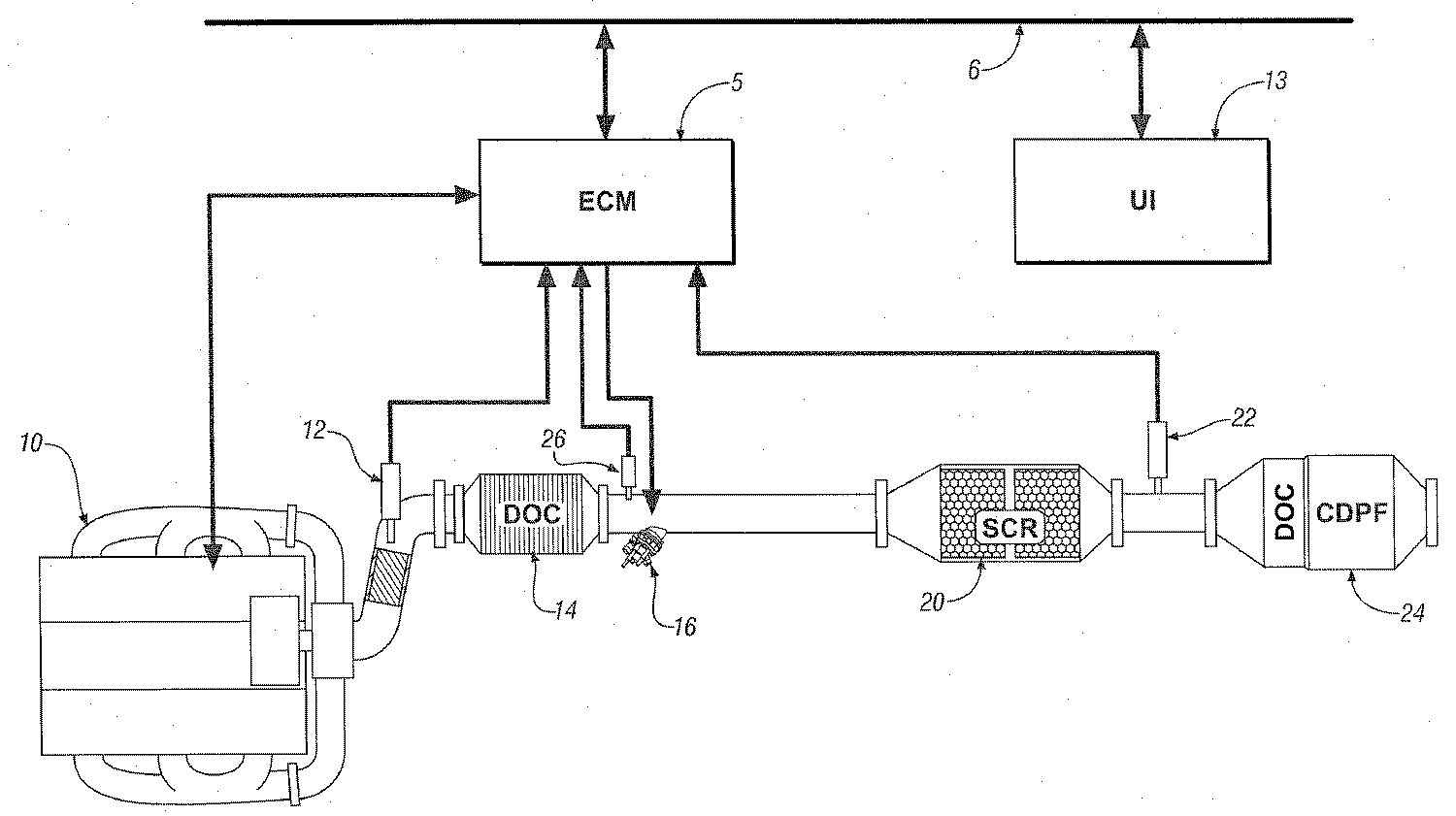
이제 도 20과 관련하여, 도면은 내부 연소 엔진, 배기 가스 후처리 시스템 및 본 발명에 따라 제조된 조절 시스템의 구현예를 도시하고 있다.예시적인 엔진 및 조절 시스템은 종래의 4-사이클 내부 연소 엔진 10 및 전기 엔진 조절 모듈 ('ECM')5을 포함한다. 상기 엔진은 주로 화학양론적으로 희박(LEAN)한 방식을 갖는 공지의 압축 점화 엔진을 포함한다. 선택적으로, 상기 엔진 10은 화학양론적으로 희박 상태에서 작동되는 엔진 조절 방법, 예를 들면, 균일 전하 압축 점화 엔진(homogeneous-charge compression-ignition engines) 및 희박 불꽃 점화 엔진(lean-burn spark-ignition engines) 중 어느 하나를 채용한 엔진을 포함할 수 있다. 상기 엔진 10은 동력 전달 장치에 견인 토크(tractive torque)를 전달하도록 자동차 동력 장치에 실시 가능하게 부착된 크랭크 축에 부착된 다수의 왕복 피스톤(reciprocating piston)을 포함한다. 상기 엔진 10은 일반적으로 특히 탄화수소('HC'), 일산화탄소('CO'), 산소의 질화물('NOx') 및 미립자 물질('PM')을 포함하는 후처리 시스템에 의해 전환되는 조절된 구성 성분을 함유하는 배기 가스 공급류를 발생시킨다. Referring now to FIG. 20, the drawings show an embodiment of an internal combustion engine, an exhaust gas aftertreatment system and a conditioning system made in accordance with the present invention. An exemplary engine and conditioning system are conventional four-cycle internal combustion engines. 10 and an electric engine conditioning module ('ECM') 5. The engine mainly comprises a known compression ignition engine having a stoichiometric lean (LEAN) manner. Optionally, the
배기 가스 후처리 시스템은 배기 가스 공급류의 구성 성분을 무해한 기체로 전환하도록 설계된 통합 시스템을 포함한다. 배기 가스 다기관은 배기 가스류(exhaust gas flow)를 배기 가스 후처리 시스템으로 들어가도록 한다. 예시적인 후처리 시스템은 산화 촉매('DOC') 14, 선택적 촉매 환원('SCR') 촉매 20 및 제2 촉매 24를 포함한다. 제 2 촉매 24는 디젤 미립자 필터('CDPF')와 혼합된 제2 산화 촉매('DOC')로 나타난다. 제 2 촉매 24는 촉매화된 또는 촉매화되지 않은 디젤 미립자 필터들, 공기 펌프, 외부 열기관, 황 트랩(sulfur traps), 인 트랩(phosphorous traps), 선택적 환원 장치 및 다른 것들을 포함하는 다른 알려진 배기 가스 후처리 장치를 단독 또는 혼합하여 포함할 수 있다. The exhaust gas aftertreatment system includes an integrated system designed to convert components of the exhaust gas feed stream into harmless gases. The exhaust gas manifold allows the exhaust gas flow to enter the exhaust gas aftertreatment system. Exemplary aftertreatment systems include oxidation catalyst ('DOC') 14, selective catalytic reduction ('SCR')
각각의 배기 가스 후처리 장치는 산화, 선택적 촉매 환원, HC 투여 및 미립자 필터링을 포함하는 배기 가스 공급류의 구성 성분 처리를 위한 다양한 성능을 가지는 기술을 채용한 장치를 포함할 수 있다. 상기 장치들은 공지의 파이프 및 연결관을 사용하여 연속하여 유동적으로 연결될 수 있다. Each exhaust gas aftertreatment device may comprise an apparatus employing a variety of performance techniques for treating components of the exhaust gas feed stream, including oxidation, selective catalytic reduction, HC dosing, and particulate filtering. The devices can be continuously and fluidly connected using known pipes and connectors.
예시적인 SCR 장치 20은 금속 조립체(metallic assembly)에 수납되고, 배기 가스 시스템의 일부로서 조립되는 은-알루미늄 촉매 담지 기판을 포함한다. 일반적으로 상기 은-알루미늄 촉매는 1 내지 4 중량%의 범위로 포함된다. 일반적으로, 상기 기판은 다수의 유체 통로 가지며, 상기 통로의 벽 위에 촉매가 코팅되어 있는 금속 또는 세라믹 모노 리스 장치를 포함한다. 상기한 바와 같이, 여기에 기재된 결과들을 위해 사용된 예시적인 SCR 장치는 코디어리트 모노리스 기판 스퀘어 인치 당 400셀로 담지된 촉매 물질을 함께, 2중량% Ag2O 담지 알루미나를 갖는 촉매 물질을 포함한다. 상기 예시적인 SCR 장치는 설명을 위한 것이며 제한적인 것은 아니다.
상기 후처리 시스템은 감지 장치 및 바람직하게는 ECM 5에 신호적으로 접촉되는 시스템을 포함한다. 상기 감지 장치는 엔진 10에서 유출되는 배기 가스 게이트를 감지하도록 작동되는 NOx 센서 12, SCR 촉매 20의 작용 온도를 결정하는 산화 촉매 14에서 유출되는 배기 가스 및 SCR 촉매 20의 상류(upstream)의 온도를 측정하도록 작동되는 온도 센서 26 및 피드백 및 분석을 위해 SCR 촉매 20 다음으로 배기 가스의 구성 성분을 모니터하도록 작동되는 배기 가스 감지 장치 22를 포함한다. 상기 NOx 센서 12는 바람직하게는 배기 가스 공급류 내의 NOx 농도에 대한 파라미터 값과 연관된 전기 신호를 발생하도록 작동되며, 배기 가스 공급류의 공연비에 대한 파라미터 값에 연관된 제2 전자 신호를 발생하도록 작동되는 센서를 포함하며, 이로부터 산소 함량을 결정할 수 있다. 배기 가스 감지 장치 22는 바람직하게는 배기 가스 공급류 내의 NOx 농도에 대한 파라미터 값과 연관된 전기적 신호를 발생시키는 제 2 NOx 센서 22를 포함한다. 선택적으로, NOx 센서 2는 실질적인 감지 장치를 포함하며, 이때 배기 가스 공급류 내의 NOx 농도는 엔진 작동 조건에 기초하여 결정되고, 이는 공지 기술이다. The aftertreatment system comprises a sensing device and preferably a system in signal contact with the
배기 가스 후처리 시스템은 조절된 양의 HC를 SCR 촉매 20 상류(upstream)에 주입하기 위한 탄화수소('HC') 투여 장치 16를 포함한다. 예시적인 HC 투여 장치는 참조로 편입된 함께 계속 중인 미국 특허 출원인 "배기 가스 공급류에 반응물을 주입하는 장치 및 방법"에 기재되어 있다. 상기 HC 투여 장치는 ECM 5에 실시 가능하게 연결되며, 일반적인 자동차 연료의 형태로 배기 가스 공급류에 HC의 주입 시간 및 양을 조절할 수 있도록 적용된다. 선택적으로 상기 엔진으로부터 탄화수소는 후-주입 조절 방법을 사용함으로써, SCR 촉매 내에서 NOx를 환원시키는 환원제 물질로서 사용될 수 있다. 이러한 구현예에서, 상기 산화 촉매 14는 후처리 시스템에 포함되지 않을 수 있다. The exhaust gas aftertreatment system includes a hydrocarbon ('HC')
상기 조절 시스템은 본 발명에 기재된 전동 기구를 포함하는 다양한 자동차 시스템의 통합된 조절을 제공하도록 적용된 다수의 조절 모듈을 포함하는 분산 조절 모듈 구조를 포함한다. 상기 조절 시스템은 감지 장치로부터 온 입력을 모니터하고, 적절한 정보를 조합하여, 작업자의 요구에 맞고, 연비, 배출, 성능, 작동가능성 및 하드웨어의 보호와 같은 파라미터들을 포함하는 조절 목적을 얻을 수 있도록 다양한 작동기를 조절하는 알고리즘을 수행한다. 상기 분산된 조절기 구조는 ECM 5를 포함하고, 다른 장치들과 작동가능하게 연결되어 있으며, 이를 통해 작동자들이 일반적으로 자동차 및 전동 장치의 작동을 조절 도는 지시할 수 있는 사용자 인터페이스('UI') 13을 포함한다. 자동차 작동자가 UI 13에 입력을 제공하는 장치들에는 가속 페달, 브레이크 페달, 기어 변속기 및 자동차 속도 크루즈 조절기가 포함된다. 상기 언급한 조절 모듈 및 장치들은 일반적으로 항목 6으로 나타나는 고속 지역 네트워트('LAN') 버스를 통해 각각 다른 조절 모듈, 장치, 센서 및 엑츄에이터와 통신한다. 상기 LAN 버스 6은 조절 파라미터들의 통신 체계 및 다양한 과정, 조절 모듈 및 장치들 사이의 지휘 체계를 제공한다. 상기 특정한 사용되는 통신 프로토콜은 적용-특정이다. 상기 LAN 버스 및 적당한 프로토콜은 확실한 통신 및 앞서 언급한 조절 모듈과 잠금 방지 브레이크, 견인력 조절 및 자동차 안정성과 같은 기능성을 제공해주는 다른 조절 모듈 사이에 멀티-조절 모듈 인터페이스를 제공한다. The regulation system includes a distributed regulation module structure comprising a plurality of regulation modules adapted to provide integrated regulation of various automotive systems including the power mechanism described herein. The control system monitors the input from the sensing device and combines the appropriate information to meet the needs of the operator and achieve various control purposes including parameters such as fuel economy, emissions, performance, operability and protection of the hardware. Perform an algorithm to adjust the actuator. The distributed regulator structure includes an
상기 ECM 5는 데이타 버스를 통해 신호적, 전기적으로 휘발성 및 비휘발성 메모리 장치와 연결된 중앙 처리 유닛을 포함한다. 상기 ECM 5는 도시된 바와 같이, 계속해서 엔진 10 및 배기 가스 후처리 장치의 작동을 모니터하고 조절하는 감 지 장치 및 다른 출력 장치에 실시가능하도록 부착된다. 상기 출력 장치는 엔진의 적당한 조절과 작동을 위해 필요한 서브시스템을 포함하는 것이 바람직하며, 예로써 공기 흡입 시스템, 연료 주입 시스템, 불꽃 점화 시스템(예를 들면, 균일-대전 압축 점화 엔진과 같은 불꽃 점화 엔진이 사용될 때), 배기 가스 재순환('EGR') 시스템 및 증발 조절 시스템 등이 포함된다. 상기 엔진 감지 장치는 엔진 작동, 외부 조건 및 자동자 요구를 모니터할 수 있는 장치를 포함하며, 일반적으로 와이어링 하네스(wiring harness)를 통해 ECM 5에 신호적으로 부착되어 있다.The
비-휘발성 메모리 장치에 저장된 알고리즘은 중앙 처리 유닛에 의해 수행되고, 감지 장치로부터 온 입력을 모니터하도록 작동될 수 있으며, 프리셋 캘리브레이션(preset calibration)을 사용하여 엔진 조절 및 엔진 작동 조절을 위한 진단 경로를 수행한다. 알고리즘은 일반적으로 프리셋 루프 사이클(preset loop cycle) 동안에, 각 루프 사이클당 적어도 한번씩 수행되는 각 조절 알고리즘과 함께 수행된다. 루프 사이클은 일반적으로 엔진 작동 중에, 각각 3.125, 6.25, 12.5, 25 및 100 밀리세컨드(milliscond) 수행된다. 선택적으로 조절 알고리즘은 사건의 발생에 반응하여 수행될 수 있다. 주기적인 사건들, 예를 들면 엔진 연료 계산과 같은 주기적인 사건은 각 엔진 주기(engine cycle)에서 수행될 수 있다. 진단 알고리즘은 엔진 키-온 사이클(engine key-on cycle)당 한번씩 수행된다. 진단 알고리즘은 실행 전에 특정한 가능성 기준을 얻기 위한 요구를 포함하는 추가적인 제한들을 가질 수 있다. 내부 연소 엔진 10의 다양한 면들을 조절하고 진단하기 위한 ECM 5의 사용은 당해 기술 분야의 숙련자들에게 잘 알려져 있다. Algorithms stored in the non-volatile memory device may be executed by a central processing unit and operated to monitor inputs from the sensing device, and may use preset calibration to establish diagnostic paths for engine regulation and engine operation regulation. Perform. The algorithm is typically performed with each adjustment algorithm that is performed at least once for each loop cycle, during the preset loop cycle. Loop cycles are generally performed during engine operation, 3.125, 6.25, 12.5, 25 and 100 millisconds, respectively. Optionally, the adjustment algorithm can be performed in response to the occurrence of the event. Periodic events, for example periodic events such as engine fuel calculations, can be performed in each engine cycle. The diagnostic algorithm is performed once per engine key-on cycle. The diagnostic algorithm may have additional limitations, including the need to obtain certain likelihood criteria before execution. The use of
150 내지 550℃ 범위의 촉매 온도들이 상기 예시적인 적용들과 관련이 있을 뿐 아니라, 상기 촉매들이 잠재적으로 노출될 수 있는 다음 범위의 기상 농도들 역시 관련이 있다: POx 연료 개질제(fuel reformer) 또는 후-주입과 같은 실린더 내 연소 조절(in-cylinder combustion control)에 의해 제공되는 O2(2-20%), NOx(25-250ppm) 및 H2 (8000ppm 까지). 또한, 사용되지 않을 때 초당 10L부터 가속 조건 하에서 초당 75L까지의 범위인 배기 가스 유속은 5L의 부피를 갖는 촉매 반응 장치에 있어서, 약 7,000h-1부터 54,000h-1의 범위에 있는 공간 속도를 가져온다. Not only are catalyst temperatures in the range of 150 to 550 ° C. related to the exemplary applications, but also the following ranges of gaseous concentrations in which the catalysts can be potentially exposed: POx fuel reformer or after O 2 (2-20%), NOx (25-250 ppm) and H 2 provided by in-cylinder combustion control such as injection (Up to 8000 ppm). Further, when not in use, exhaust gas flow rates ranging from 10 liters per second to 75 liters per second under accelerated conditions, for a catalytic reaction apparatus having a volume of 5 liters, have a space velocity in the range of about 7,000 h −1 to 54,000 h −1 . Bring.
디젤 연료에 존재하는 중탄화수소(heavier hydrocarbon)(예를 들면 n-도데칸)는 저온 범위에서 NOx 전환을 제공하며, 배기 가스 내로 2차 연료 주입의 투입을 용이하게 해준다. 공급류에 수소를 첨가하는 것은 가벼운 탄화수소(프로펜, 프로판) 및 무서운 탄화수소(n-도데칸) 모두에 있어서, Ag/Al2O3 촉매 상의 NOx 전환율에 대한 활성화 온도를 또한 낮춘다. 배기 가스 공급류 내로의 일산화탄소의 첨가는 Ag/Al2O3 상의 NOx 환원을 나타내지 않는다. Heavier hydrocarbons (eg n-dodecane) present in diesel fuel provide NOx conversion in the low temperature range and facilitate the injection of secondary fuel into the exhaust gas. The addition of hydrogen to the feed stream is a combination of Ag / Al 2 O 3 for both light hydrocarbons (propene, propane) and dread hydrocarbons (n-dodecane). The activation temperature for the NOx conversion on the catalyst is also lowered. The addition of carbon monoxide into the exhaust gas feed stream was made from Ag / Al 2 O 3 top NOx reduction is not shown.
채택된 특정한 조절 방법, 즉, 본 발명에 기재된 HC 주입량 대 H2 주입량 대 NO2 증류는 결국 입구 NOx 농도뿐 아니라, SV 및 HC-SCR 촉매의 온도에 의존한다. 코크 형성 및 SCR 촉매의 가능한 비활성화를 최소화하기 위해서 과량의 HC를 주입하지 않도록 케어(care)는 공급류 내에 과량의 H2 첨가 없이(즉, ≤250ppm H2) 낮은 O2 농도(<10%) 및/또는 낮은 온도(<350℃)에서 수행되어야 한다. The particular control method employed, ie the HC injection volume vs. H 2 injection volume versus NO 2 distillation, described herein, depends in turn on the temperature of the SV and HC-SCR catalysts as well as the inlet NOx concentration. Care should be taken to avoid injecting excess HC in order to minimize coke formation and possible deactivation of the SCR catalyst, with low O2 concentration (<10%) and without excess H 2 addition (i.e. ≤ 250 ppm H 2 ) in the feed stream. And / or at low temperatures (<350 ° C.).
엔진 작동 진행 중에 조절될 수 있는 배기 가스 조건에는 SCR 촉매에 대한 NOx의 환원을 위해 사용되는 디젤 연료, 즉 탄화수소('HC')의 주입량, POx 연료 개질제 또는 실린더 내 후-주입 조절 방법으로부터 온 H2 주입량이 포함된다. 또한, EGR의 크기(%) 및 PCCI('premixed charge compression ignition') 연소가 낮은 엔진-아웃 NOx 농도에 사용될 수 있으며, 배기 가스 공급류에서 O2 농도를 다양화할 수 있다. Exhaust gas conditions that can be regulated during engine operation include H fuel from diesel fuel used for the reduction of NOx to the SCR catalyst, ie hydrocarbon ('HC') injection, POx fuel modifiers or post-injection control methods in the cylinder. 2 injection amounts are included. In addition, the percentage of EGR and 'premixed charge compression ignition' (PCCI) combustion can be used for low engine-out NOx concentrations and can vary the O 2 concentration in the exhaust gas feed stream.
본 발명은 희박 화학양론 작동 동안의 예시적인 내부 연소 엔진의 작동 조건 조절을 통해 가스 공급류 내의 엔진-아웃 NOx 농도를 N2로 선택적으로 환원시키는 방법을 포함한다. 이것은 배기 가스 공급류의 선택된 파라미터를 기초로 배기 가스 공급류 내의 NOx 가스 및 바람직한 탄화수소/NOx 비율의 측정을 결정하는 단계; 및 Ag-Al 촉매반응 장치 20의 상류 배기 가스 공급류 내에 탄화수소 환원제를 선택적으로 넣는 단계를 포함하여 이루어진다. 연료는 은-알루미늄 촉매 반응 장치 20 내에서 NOx를 감소시키는데 바람직한 환원제이다. 엔진 작동 조건 및 배기 가스 온도범위는 최적의 NOx 전환율을 얻기 위해 한정된다. 관심있는 배기 가스 파라미터에는 촉매 작용 온도, 배기 가스 유속, NOx 농도 및 산소 농도가 포함된다. 상기 파라미터들은 바람직하게는 특정한 작동 조건에서 NOx 환원에 있어서 최적인 HC1/NOx 비율을 계산하기 위한 조절 시스템으로 사용된다. 상기 HC1/NOx 비율은 C1 기초에서 입구 NOx 농도에 의해 나누어진 주입되는 연료의 양으로 정의된다(예를 들면, 1ppm 증류된 디젤 연료는 약 14 탄소 원자를 가지며; 따라서, HC1 : NOx 비율이 10이고, 배기 가스 공급류 내의 100ppm 입구 NOx가 존재하면, 10 ×100/14 = 71ppm 디젤 연료의 주입이 요구된다). 상기 HC1/NOx 비율은 촉매에 대한 NOx 환원에 있어서, 정확한 연료의 양을 계산하고 주입하는데 사용된다. 상기 엔진 작동 파라미터는 또한, NOx 환원에 있어서 최적 수소 농도를 계산하는데 사용되며, 상기 수소 농도는 부분 산화 연료 개질제 또는 실린더 내 후-주입 시스템과 같이 사용가능한 방법을 통해 배기 가스 공급류 내에 주입될 수 있다. 주어진 엔진에 대하여 최적의 촉매 부피를 찾는 기준은 배기 가스 부피 유속/촉매 부피 = 공간 속도 (h-1) 를 포함하여 정의된다. 더 나아가 본 발명에 기재된 발명은 2% 만큼 낮은 엔진 아웃 O2에서 높은 NOx 전환율을 얻는데 효과적이다. 촉매에 대한 최적의 NOx 전환율을 얻기 위해 엔진 아웃 NOx 및 O2 농도를 변화시키는 EGR과 PCCI와 같은 이러한 엔진 조절 설계 및 다른 저온 연소 방법들이 채택된다. 최적 NOx 전환율을 얻기 위한 엔진 아웃 NOx 수준과 엔진 아웃 O2 수준 사이의 교환이 설명된다. 낮은 온도에서 NOx 전환율의 최적값을 얻기 위해서 NO(1차 엔진 아웃 NOx 종)를 NO2로 산화시키는 NOx 환원 촉매의 상류에 공지의 디젤 산화 촉매 또는 공지의 플라즈마 오존 발생 장치가 사용될 수 있다. 낮은 온도에서는 적은 양의 연료 환원제와 많은 양의 H2가 주입되는 것이 바람직하다. 반대로, 높은 온도에서는 많은 양의 연료 환원제와 적은 양의 H2가 주입된다. 높은 배기 가스 흐름 조건에서는 더 많은 양의 H2가 주입된다. 상기 한 작동 파라미터들은 촉매 형성, 예를 들면, 은-금속 로딩, 워시코트 로딩 및 다른 비-은 성분 첨가에 기초하는 NOx 환원에 있어서, HC1/NOx 비율의 최적값을 계산하는데 사용된다. 이러한 조절 방법의 사용은 EGR, PCCI(저온) 연소, 주입된 연료의 양 및 주입된 H2의 양의 조합을 통해 촉매에 대한 NOx 환원의 최대값을 얻는 동시에 자동차 연료 효율을 최적화할 수 있도록 해준다. 더 나아가 높은 공간 속도, 낮은 O2 농도 및 낮은 온도 하에서 주입되는 반응물의 사용을 위한 작동 한계는 잠재적인 코크(coke) 형성(탄소 침전물) 및 가능한 촉매 비활성화를 배기 가스 공급류 내에 과량의 수소를 첨가하지 않고 최소화하는 것으로 정의될 수 있다. 최적 NOx 전환율을 얻을 수 있는 연료 조성을 확인할 수 있다.The present invention includes a method for selectively reducing the engine-out NOx concentration in the gas feed stream to N2 through adjusting operating conditions of an exemplary internal combustion engine during lean stoichiometric operation. This includes determining a measurement of the NOx gas and the desired hydrocarbon / NOx ratio in the exhaust gas feed based on the selected parameter of the exhaust gas feed stream; And selectively introducing a hydrocarbon reducing agent into the upstream exhaust gas feed stream of the Ag-
본 발명은 바람직한 구현예 및 그에 대한 변형을 특히 참조하여 기술되었다. 나아가, 본 명세서를 읽고 이해함으로써, 다른 사람들이 이를 수정 및 변경할 수 있을 것이다. 이러한 모든 수정 및 변경은 본 발명의 범주 내에 있는 한, 모두 포함된다고 여겨진다.
The present invention has been described with particular reference to preferred embodiments and variations thereof. Furthermore, by reading and understanding this specification, others will be able to modify and change it. All such modifications and variations are intended to be included as long as they are within the scope of the present invention.
본 발명은 특정 부분 및 부분들의 배치, 본 명세서의 일부인 부합되는 도면에 의해 자세히 묘사되고, 설명되는 구현예에 있어서, 물리적인 형태를 취할 수 있다. 그리고, 여기에서:The invention is described in detail by the specific part and arrangement of parts, the corresponding drawings which are part of this specification, and in the described embodiments, may take the physical form. And here:
도 1 ~ 19는 본 발명에 의한 데이타 그래프이며, 1 to 19 is a data graph according to the present invention,
도 20은 본 발명에 의한 전동기 시스템의 개략적인 도면이다.20 is a schematic diagram of an electric motor system according to the present invention.
Claims (42)
Applications Claiming Priority (2)
| Application Number | Priority Date | Filing Date | Title |
|---|---|---|---|
| US11/533,434 US8006481B2 (en) | 2006-09-20 | 2006-09-20 | Method and apparatus to selectively reduce NOx in an exhaust gas feedstream |
| US11/533,434 | 2006-09-20 |
Publications (2)
| Publication Number | Publication Date |
|---|---|
| KR20080026520A KR20080026520A (en) | 2008-03-25 |
| KR100959318B1 true KR100959318B1 (en) | 2010-05-26 |
Family
ID=39187132
Family Applications (1)
| Application Number | Title | Priority Date | Filing Date |
|---|---|---|---|
| KR1020070095622A KR100959318B1 (en) | 2006-09-20 | 2007-09-20 | METHOD AND APPARATUS TO SELEXTIVELY REDUCE NOx IN AN EXHAUST GAS FEEDSTREAM |
Country Status (4)
| Country | Link |
|---|---|
| US (1) | US8006481B2 (en) |
| KR (1) | KR100959318B1 (en) |
| CN (1) | CN101219339B (en) |
| DE (1) | DE102007044192B4 (en) |
Cited By (1)
| Publication number | Priority date | Publication date | Assignee | Title |
|---|---|---|---|---|
| KR20220131689A (en) | 2021-03-22 | 2022-09-29 | 한국전력공사 | Control method of exhaust gas purification device |
Families Citing this family (38)
| Publication number | Priority date | Publication date | Assignee | Title |
|---|---|---|---|---|
| CN100577996C (en) * | 2004-12-14 | 2010-01-06 | 沃尔沃拉斯特瓦格纳公司 | Method and device for diagnosing oxide catalyst |
| US7591132B2 (en) * | 2006-09-20 | 2009-09-22 | Gm Global Technology Operations, Inc. | Apparatus and method to inject a reductant into an exhaust gas feedstream |
| JP4737098B2 (en) * | 2007-01-24 | 2011-07-27 | 株式会社デンソー | Diagnostic device for internal combustion engine |
| EP2126297B1 (en) | 2007-02-21 | 2015-01-28 | Volvo Lastvagnar AB | Method for operating an exhaust aftertreatment system and exhaust aftertreatment system |
| FR2922594A1 (en) * | 2007-10-23 | 2009-04-24 | Peugeot Citroen Automobiles Sa | METHOD FOR UREA INJECTION MANAGEMENT IN A SELECTIVE CATALYTIC REDUCTION SYSTEM |
| US9518492B2 (en) * | 2008-04-23 | 2016-12-13 | Caterpillar Inc. | Exhaust system implementing in situ calibration |
| US7896645B2 (en) * | 2008-05-30 | 2011-03-01 | Universal Cleanair Technologies | Three phased combustion system |
| US8245500B2 (en) * | 2008-07-07 | 2012-08-21 | Delphi Technologies, Inc. | Dual catalyst NOx reduction system for exhaust from lean burn internal combustion engines |
| US7964167B2 (en) * | 2008-10-03 | 2011-06-21 | GM Global Technology Operations LLC | Method and architecture for oxidizing nitric oxide in exhaust gas from hydrocarbon fuel source with a fuel lean combustion mixture |
| US8377400B2 (en) * | 2008-10-03 | 2013-02-19 | GM Global Technology Operations LLC | Methods and systems for oxidizing nitric oxide in a gas stream |
| US20100101221A1 (en) * | 2008-10-28 | 2010-04-29 | Caterpillar Inc. | CATALYSTS, SYSTEMS, AND METHODS FOR REDUCING NOx IN AN EXHAUST GAS |
| US20100112191A1 (en) * | 2008-10-30 | 2010-05-06 | Micron Technology, Inc. | Systems and associated methods for depositing materials |
| US8181451B2 (en) * | 2008-11-20 | 2012-05-22 | Alstom Technology Ltd | Method of controlling the operation of a selective catalytic reduction plant |
| US20100140137A1 (en) * | 2008-12-10 | 2010-06-10 | Deluga Gregg A | Fuel conversion system, apparatus, and method |
| KR101030394B1 (en) * | 2008-12-31 | 2011-04-20 | 연세대학교 산학협력단 | apparatus for engine-emission reduction using reformer, reformer used therefor and apparatus for engine-emission reduction using the same |
| US20100192545A1 (en) * | 2009-01-30 | 2010-08-05 | Gm Global Technology Operations, Inc. | Exhaust aftertreatment system |
| US8033167B2 (en) * | 2009-02-24 | 2011-10-11 | Gary Miller | Systems and methods for providing a catalyst |
| US8505279B2 (en) * | 2009-03-26 | 2013-08-13 | GM Global Technology Operations LLC | Exhaust gas treatment system including a four-way catalyst and urea SCR catalyst and method of using the same |
| US8555617B2 (en) * | 2009-03-26 | 2013-10-15 | GM Global Technology Operations LLC | Exhaust gas treatment system including a four-way catalyst and urea SCR catalyst and method of using the same |
| US8109081B2 (en) | 2009-05-19 | 2012-02-07 | GM Global Technology Operations LLC | Hydrocarbon selective catalytic reduction for NOx control with gasoline-fueled spark ignition engines using engine-out hydrocarbons |
| US8635855B2 (en) * | 2009-06-17 | 2014-01-28 | GM Global Technology Operations LLC | Exhaust gas treatment system including a lean NOx trap and two-way catalyst and method of using the same |
| US8904760B2 (en) * | 2009-06-17 | 2014-12-09 | GM Global Technology Operations LLC | Exhaust gas treatment system including an HC-SCR and two-way catalyst and method of using the same |
| US8409515B2 (en) * | 2009-07-14 | 2013-04-02 | GM Global Technology Operations LLC | Exhaust gas treatment system |
| KR101158816B1 (en) | 2009-08-21 | 2012-06-26 | 기아자동차주식회사 | Exhaust Device Of Diesel Vehicle |
| US20120079813A1 (en) * | 2010-10-05 | 2012-04-05 | Gm Global Technology Operations, Inc. | OPERATING METHODS FOR SELECTIVE CATALYTIC REDUCTION OF NOx |
| CN102762281B (en) * | 2011-02-18 | 2015-04-08 | 丰田自动车株式会社 | Exhaust conversion apparatus for internal combustion engine |
| EP2754866A4 (en) * | 2011-09-05 | 2015-04-22 | Hino Motors Ltd | Exhaust gas purification apparatus |
| CN103159242A (en) * | 2011-12-16 | 2013-06-19 | 中国科学院生态环境研究中心 | Preparation method of nordstrandite and purpose thereof |
| US8920756B2 (en) * | 2012-05-07 | 2014-12-30 | GM Global Technology Operations LLC | Silver promoted close-coupled NOx absorber |
| CN102688672A (en) * | 2012-06-08 | 2012-09-26 | 深圳市泓耀环境科技发展股份有限公司 | Denitration method for waste gas generated by burning system and denitration device thereof |
| GB201222302D0 (en) | 2012-12-12 | 2013-01-23 | Ford Global Tech Llc | A method of operating a diesel engine system having LNT and SCR aftertreatment devices |
| US9512762B2 (en) * | 2014-08-13 | 2016-12-06 | Southwest Research Institute | Internal combustion engine having dedicated cylinder(s) for generation of both EGR and exhaust aftertreatment reductant for NOx-reducing catalyst |
| JP6369455B2 (en) * | 2015-12-24 | 2018-08-08 | 株式会社デンソー | Ozone supply control device |
| US9714594B1 (en) * | 2016-01-21 | 2017-07-25 | GM Global Technology Operations LLC | Control of hydrocarbon injection rate in an exhaust gas assembly |
| US10113464B2 (en) * | 2016-12-08 | 2018-10-30 | GM Global Technology Operations LLC | Method and apparatus for controlling reductant injection into an exhaust gas feedstream from an internal combustion engine |
| DE102018203126A1 (en) | 2018-03-02 | 2019-09-05 | Ford Global Technologies, Llc | Process for exhaust aftertreatment |
| DE112019007304T5 (en) | 2019-05-09 | 2022-02-17 | Cummins Emission Solutions Inc. | VALVE ARRANGEMENT FOR SPLIT-FLOW CATALYTIC CONVERTER IN CLOSE-COUPLED CONSTRUCTION |
| CN110461082B (en) * | 2019-07-10 | 2021-11-30 | 江苏天楹环保能源成套设备有限公司 | Device and method for reducing NOx content in flame of air plasma torch |
Citations (3)
| Publication number | Priority date | Publication date | Assignee | Title |
|---|---|---|---|---|
| JP2006022729A (en) | 2004-07-08 | 2006-01-26 | Hino Motors Ltd | Control method of exhaust emission control device |
| KR20060012642A (en) * | 2003-05-22 | 2006-02-08 | 히노 지도샤 가부시키가이샤 | Exhaust gas purifier |
| KR20060054423A (en) * | 2003-08-05 | 2006-05-22 | 엥겔하드 코포레이션 | Emission treatment system and method using a scr filter |
Family Cites Families (22)
| Publication number | Priority date | Publication date | Assignee | Title |
|---|---|---|---|---|
| JP3375645B2 (en) * | 1991-05-14 | 2003-02-10 | 株式会社日立製作所 | Control device for internal combustion engine |
| JP3440290B2 (en) | 1993-08-26 | 2003-08-25 | 独立行政法人産業技術総合研究所 | Exhaust gas purification method |
| DE4404617C2 (en) | 1994-02-14 | 1998-11-05 | Daimler Benz Ag | Device for the selective catalyzed NO¶x¶ reduction in oxygen-containing exhaust gases from internal combustion engines |
| DE4441261A1 (en) | 1994-11-19 | 1996-05-23 | Bosch Gmbh Robert | Device for the aftertreatment of exhaust gases from an internal combustion engine |
| US5727385A (en) | 1995-12-08 | 1998-03-17 | Ford Global Technologies, Inc. | Lean-burn nox catalyst/nox trap system |
| US5921076A (en) * | 1996-01-09 | 1999-07-13 | Daimler-Benz Ag | Process and apparatus for reducing nitrogen oxides in engine emissions |
| JP3066607B2 (en) * | 1996-04-26 | 2000-07-17 | 株式会社小松製作所 | Device and method for regenerating NOx catalyst for diesel engine |
| US6038854A (en) * | 1996-08-19 | 2000-03-21 | The Regents Of The University Of California | Plasma regenerated particulate trap and NOx reduction system |
| GB9802504D0 (en) | 1998-02-06 | 1998-04-01 | Johnson Matthey Plc | Improvements in emission control |
| US5980844A (en) * | 1998-04-09 | 1999-11-09 | Asec Manufacturing | SO2 -tolerant silver oxide catalysts |
| US6293096B1 (en) * | 1999-06-23 | 2001-09-25 | Southwest Research Institute | Multiple stage aftertreatment system |
| US6311484B1 (en) | 2000-02-22 | 2001-11-06 | Engelhard Corporation | System for reducing NOx transient emission |
| US7135153B2 (en) | 2002-03-07 | 2006-11-14 | Southwest Research Institute | NOx reduction system for diesel engines, using hydrogen selective catalytic reduction |
| US7134273B2 (en) * | 2002-09-04 | 2006-11-14 | Ford Global Technologies, Llc | Exhaust emission control and diagnostics |
| CN100355488C (en) | 2003-05-07 | 2007-12-19 | 韩国高化环保技术有限公司 | Catalytic process for nitrogen oxides reduction by multi-injection and use thereof |
| US7378069B2 (en) | 2004-07-27 | 2008-05-27 | Los Alamos National Security, Llc | Catalyst and method for reduction of nitrogen oxides |
| US7146802B2 (en) | 2004-10-07 | 2006-12-12 | General Motors Corporation | Reducing NOx emissions with a staged catalyst |
| US7743602B2 (en) * | 2005-06-21 | 2010-06-29 | Exxonmobil Research And Engineering Co. | Reformer assisted lean NOx catalyst aftertreatment system and method |
| US7389638B2 (en) * | 2005-07-12 | 2008-06-24 | Exxonmobil Research And Engineering Company | Sulfur oxide/nitrogen oxide trap system and method for the protection of nitrogen oxide storage reduction catalyst from sulfur poisoning |
| US7063642B1 (en) * | 2005-10-07 | 2006-06-20 | Eaton Corporation | Narrow speed range diesel-powered engine system w/ aftertreatment devices |
| US20100024400A1 (en) * | 2008-08-01 | 2010-02-04 | General Electric Company | Emission control system and method |
| US20100077733A1 (en) * | 2008-09-26 | 2010-04-01 | Benjamin Hale Winkler | Emission system, apparatus, and method |
-
2006
- 2006-09-20 US US11/533,434 patent/US8006481B2/en not_active Expired - Fee Related
-
2007
- 2007-09-17 DE DE102007044192.6A patent/DE102007044192B4/en not_active Expired - Fee Related
- 2007-09-20 CN CN2007101527657A patent/CN101219339B/en not_active Expired - Fee Related
- 2007-09-20 KR KR1020070095622A patent/KR100959318B1/en not_active IP Right Cessation
Patent Citations (3)
| Publication number | Priority date | Publication date | Assignee | Title |
|---|---|---|---|---|
| KR20060012642A (en) * | 2003-05-22 | 2006-02-08 | 히노 지도샤 가부시키가이샤 | Exhaust gas purifier |
| KR20060054423A (en) * | 2003-08-05 | 2006-05-22 | 엥겔하드 코포레이션 | Emission treatment system and method using a scr filter |
| JP2006022729A (en) | 2004-07-08 | 2006-01-26 | Hino Motors Ltd | Control method of exhaust emission control device |
Cited By (1)
| Publication number | Priority date | Publication date | Assignee | Title |
|---|---|---|---|---|
| KR20220131689A (en) | 2021-03-22 | 2022-09-29 | 한국전력공사 | Control method of exhaust gas purification device |
Also Published As
| Publication number | Publication date |
|---|---|
| KR20080026520A (en) | 2008-03-25 |
| CN101219339A (en) | 2008-07-16 |
| DE102007044192A1 (en) | 2008-06-12 |
| US20080066456A1 (en) | 2008-03-20 |
| US8006481B2 (en) | 2011-08-30 |
| CN101219339B (en) | 2013-07-24 |
| DE102007044192B4 (en) | 2016-10-20 |
Similar Documents
| Publication | Publication Date | Title |
|---|---|---|
| KR100959318B1 (en) | METHOD AND APPARATUS TO SELEXTIVELY REDUCE NOx IN AN EXHAUST GAS FEEDSTREAM | |
| KR100957598B1 (en) | Method and apparatus to control injection of a reductant into an exhaust gas feedstream | |
| KR100919649B1 (en) | Apparatus and method to inject a reductant into an exhaust gas feedstream | |
| US8991161B2 (en) | DeNOx of diesel engine exhaust gases using a temperature-controlled precatalyst for providing NO2 in accordance with the requirements | |
| JP5843817B2 (en) | Compression ignition engine and exhaust mechanism therefor | |
| US7426825B2 (en) | Method and apparatus for urea injection in an exhaust aftertreatment system | |
| US9138686B2 (en) | Carbon monoxide-selective oxidation catalysts | |
| US8245500B2 (en) | Dual catalyst NOx reduction system for exhaust from lean burn internal combustion engines | |
| US7650747B2 (en) | Method and apparatus for exhaust gas purifying using hydrocarbon-selective catalytic reduction | |
| EP1799332B1 (en) | Method and system for decomposing nitrogen dioxide | |
| US20110120093A1 (en) | Process and apparatus for purifying exhaust gases from an internal combustion engine | |
| CN110857642B (en) | Maintaining highly passive soot oxidation while DEF dosing using multiple dosing locations | |
| US20120079813A1 (en) | OPERATING METHODS FOR SELECTIVE CATALYTIC REDUCTION OF NOx | |
| KR20050044672A (en) | System and methods for improved emission control of internal combustion engines | |
| US20180223712A1 (en) | Vehicle having a nitrogen oxides storage converter and on-board method for monitoring and diagnosing the nitrogen oxides storage converter | |
| CN103016119A (en) | On-board diagnostic method for NO2 formation in an oxidation catalyst | |
| US9255537B2 (en) | Rejuvenation control of palladium-only diesel oxidation catalyst | |
| KR20200096016A (en) | Co clean-up catalyst, after treatment system and after treatment method | |
| EP1536111B1 (en) | Apparatus and method for removal of by-products from exhaust gases of a combustion engine | |
| WO2012128673A1 (en) | Exhaust aftertreatment system where an activator material is added to the reductant fed to the catalytic converter | |
| US6592833B1 (en) | Method of NOx abatement in high temperature lean NOx catalyst systems | |
| KR20200134608A (en) | Exhaust gas post processing apparatus | |
| Hirata et al. | Development of an improved urea-selective catalytic reduction—diesel particulate filter system for heavy-duty commercial vehicles | |
| Simescu et al. | A novel approach for diesel NOx/PM reduction | |
| Aversa | Investigation on the Performance of a Long Breathing Lean NO x Trap Using n-Butanol |
Legal Events
| Date | Code | Title | Description |
|---|---|---|---|
| A201 | Request for examination | ||
| E902 | Notification of reason for refusal | ||
| E902 | Notification of reason for refusal | ||
| E701 | Decision to grant or registration of patent right | ||
| GRNT | Written decision to grant | ||
| FPAY | Annual fee payment |
Payment date: 20130419 Year of fee payment: 4 |
|
| FPAY | Annual fee payment |
Payment date: 20140418 Year of fee payment: 5 |
|
| FPAY | Annual fee payment |
Payment date: 20150416 Year of fee payment: 6 |
|
| FPAY | Annual fee payment |
Payment date: 20160418 Year of fee payment: 7 |
|
| FPAY | Annual fee payment |
Payment date: 20170421 Year of fee payment: 8 |
|
| LAPS | Lapse due to unpaid annual fee |