KR100891782B1 - Apparatus and method for correcting of forward error in high data transmission system - Google Patents
Apparatus and method for correcting of forward error in high data transmission system Download PDFInfo
- Publication number
- KR100891782B1 KR100891782B1 KR1020020032690A KR20020032690A KR100891782B1 KR 100891782 B1 KR100891782 B1 KR 100891782B1 KR 1020020032690 A KR1020020032690 A KR 1020020032690A KR 20020032690 A KR20020032690 A KR 20020032690A KR 100891782 B1 KR100891782 B1 KR 100891782B1
- Authority
- KR
- South Korea
- Prior art keywords
- message
- node
- value
- check
- variable node
- Prior art date
Links
Images


Classifications
-
- H—ELECTRICITY
- H04—ELECTRIC COMMUNICATION TECHNIQUE
- H04B—TRANSMISSION
- H04B7/00—Radio transmission systems, i.e. using radiation field
- H04B7/005—Control of transmission; Equalising
-
- H—ELECTRICITY
- H03—ELECTRONIC CIRCUITRY
- H03M—CODING; DECODING; CODE CONVERSION IN GENERAL
- H03M13/00—Coding, decoding or code conversion, for error detection or error correction; Coding theory basic assumptions; Coding bounds; Error probability evaluation methods; Channel models; Simulation or testing of codes
- H03M13/65—Purpose and implementation aspects
- H03M13/6577—Representation or format of variables, register sizes or word-lengths and quantization
- H03M13/658—Scaling by multiplication or division
-
- H—ELECTRICITY
- H03—ELECTRONIC CIRCUITRY
- H03M—CODING; DECODING; CODE CONVERSION IN GENERAL
- H03M13/00—Coding, decoding or code conversion, for error detection or error correction; Coding theory basic assumptions; Coding bounds; Error probability evaluation methods; Channel models; Simulation or testing of codes
- H03M13/03—Error detection or forward error correction by redundancy in data representation, i.e. code words containing more digits than the source words
- H03M13/05—Error detection or forward error correction by redundancy in data representation, i.e. code words containing more digits than the source words using block codes, i.e. a predetermined number of check bits joined to a predetermined number of information bits
- H03M13/11—Error detection or forward error correction by redundancy in data representation, i.e. code words containing more digits than the source words using block codes, i.e. a predetermined number of check bits joined to a predetermined number of information bits using multiple parity bits
- H03M13/1102—Codes on graphs and decoding on graphs, e.g. low-density parity check [LDPC] codes
- H03M13/1105—Decoding
- H03M13/1111—Soft-decision decoding, e.g. by means of message passing or belief propagation algorithms
- H03M13/1117—Soft-decision decoding, e.g. by means of message passing or belief propagation algorithms using approximations for check node processing, e.g. an outgoing message is depending on the signs and the minimum over the magnitudes of all incoming messages according to the min-sum rule
- H03M13/112—Soft-decision decoding, e.g. by means of message passing or belief propagation algorithms using approximations for check node processing, e.g. an outgoing message is depending on the signs and the minimum over the magnitudes of all incoming messages according to the min-sum rule with correction functions for the min-sum rule, e.g. using an offset or a scaling factor
Abstract
가. 청구범위에 기재된 발명이 속한 기술분야end. The technical field to which the invention described in the claims belongs
본 발명은 디지털 통신 시스템에서 순방향 오류 정정(Forward Error Correction : FEC)에 관한 장치 및 방법에 관한 것으로, 특히 고속의 데이터를 전송하는 디지털 통신 시스템에서 순방향 오류 정정 부호를 복호하는 장치 및 방법에 관한 것이다.The present invention relates to an apparatus and method for forward error correction (FEC) in a digital communication system, and more particularly, to an apparatus and method for decoding a forward error correction code in a digital communication system transmitting high speed data. .
나. 발명이 해결하고자 하는 기술적 과제I. The technical problem to be solved by the invention
본 발명은 간단한 순방향 오류 정정 부호의 복호 장치 및 방법을 제공하며, sum-product 알고리즘을 사용하는 경우 간단하게 처리할 수 있고, 각 노드마다의 계산량을 줄일 수 있으며, LDPC 성능을 최대한 유지하는 장치 및 방법을 제공함에 있다.The present invention provides a simple apparatus and method for decoding a forward error correction code, and can be easily processed when using the sum-product algorithm, reduce the amount of calculation for each node, and to maintain the maximum LDPC performance and In providing a method.
다. 발명의 해결방법의 요지All. Summary of Solution of the Invention
본 발명의 방법은 저밀도 패리티 검사 코드를 이용하는 통신 시스템에서 순방향 오류 정정 부호를 복호하는 방법에 있어서, 무선 채널을 통해 수신된 부호 비트들이 영(zero)일 확률과 일일 확률의 비로 나타나는 로그 우드율(LLR) 값으로 변환된 값을 변수 노드들의 초기 메시지의 값으로 설정하는 과정과, 각 변수 노드로 입력된 메시지를 상기 각 변수 노드와 연결된 각 검사 노드로 전달하는 전달 과정과, 상기 각 검사 노드가 자신과 연결된 변수 노드들로부터 전달된 메시지들 중 절대값이 최소인 값을 가지는 메시지를 검사하고, 갱신된 메시지를 전달할 변수 노드로부터 전달된 메시지를 제외한 다른 메시지들의 부호의 곱을 계산하여 상기 최소인 값을 가지는 메시지의 부호로 결정하고, 상기 결정된 부호와 상기 최소인 값을 가지는 메시지를 상기 갱신된 메시지로 구하는 검사 노드 갱신 과정과, 상기 각 변수 노드가 자신과 연결된 검사 노드들로부터 각각 상기 갱신된 메시지를 수신하고, 상기 수신된 갱신된 메시지들의 각 부호와 상기 초기 메시지의 부호가 모두 동일할 경우 1의 가중치를 적용하고, 적어도 하나의 부호가 동일하지 않은 경우 1보다 작은 미리 설정된 값의 가중치를 상기 갱신된 메시지를 전달한 검사 노드를 제외한 다른 모든 검사 노드들로부터 수신된 메시지의 합에 적용한 값과 해당 변수 노드의 상기 초기 메시지의 값을 가산하여 상기 초기 메시지를 갱신하는 변수 노드 갱신 과정과, 상기 각 변수 노드가 자신과 연결된 검사 노드들로부터 수신한 메시지들과 초기 입력된 로그 우도율을 가산하여 로그 우도율을 갱신하는 과정과, 상기 갱신된 로드 우도율값들을 경판정하고, 상기 경판정된 값들을 이용하여 저밀도 패리티 코드 행렬의 패리티 검사를 수행하는 패리티 검사 과정을 포함한다.The method of the present invention is a method of decoding a forward error correcting code in a communication system using a low density parity check code, wherein the log wood ratio represented by the ratio of the probability that the code bits received through the wireless channel are zero to the daily probability ( LLR) setting the value converted to the value of the initial message of the variable nodes, passing the message input to each variable node to each check node connected to each variable node, and each check node The message having the minimum value among the messages transmitted from the variable nodes connected to the node is examined, and the product of the sign of other messages except for the message transmitted from the variable node to which the updated message is delivered is calculated to be the minimum value. The message having the minimum value and the determined sign and the determined A check node update process for obtaining a updated message, and each variable node receives the updated message from check nodes connected to the variable node, and each sign of the received updated messages and the sign of the initial message may be the same. In the case where a weight of 1 is applied and at least one sign is not the same, a weight of a preset value smaller than 1 is applied to the sum of messages received from all other check nodes except the check node that delivered the updated message. And a variable node updating process of updating the initial message by adding the value of the initial message of the corresponding variable node, and adding the messages received from the check nodes connected to each variable node and the initial input log likelihood ratio. Updating the log likelihood ratio, and hardly determining the updated load likelihood ratio values, Using hard decision group value comprises a parity check step of performing a parity check matrix for low density parity code.
또한, 본 발명은 행들과 열들의 저밀도 패리티 검사 행렬들로 상기 열의 수를 가지는 이진 비트들을 부호화하여 무선 채널을 통해 전송된 부호 비트들을 복호화하는 순방향 오류 정정 부호를 복호하는 장치에 있어서, 상기 무선 채널을 통해 수신된 상기 부호 비트들이 영(zero)일 확률과 일일 확률의 비로 나타나는 로그 우도율(LLR) 값으로 변환된 값을 변수 노드들의 초기 메시지의 값으로 설정하고, 입력된 메시지를 자신과 연결된 검사 노드들로 전달한 후, 상기 자신과 연결된 검사 노드들로부터 각각 갱신된 메시지들을 수신하며, 상기 검사 노드들로부터 수신된 갱신된 메시지들의 각 부호와 상기 초기 메시지의 부호가 모두 동일할 경우 1의 가중치를 적용하고, 적어도 하나의 부호가 동일하지 않은 경우 1보다 작은 미리 설정된 값의 가중치를 상기 갱신된 메시지를 전달한 검사 노드를 제외한 다른 모든 검사 노드들로부터 수신된 메시지들의 합에 적용한 값과 해당 변수 노드의 상기 초기 메시지의 값을 가산하여 상기 초기 메시지를 갱신하여 이를 출력하는 변수 노드 메시지 결정 장치와, 자신과 연결된 변수 노드들로부터 전달된 메시지들 중 절대값이 최소인 값을 가지는 메시지를 검사하고, 갱신된 메시지를 전달할 변수 노드로부터 전달된 메시지를 제외한 다른 메시지들의 부호의 곱을 계산하여 상기 최소인 값을 가지는 메시지의 부호로 결정하고, 상기 결정된 부호와 상기 최소인 값을 가지는 메시지를 상기 갱신된 메시지로 구하여 출력하는 검사 노드 메시지 결정 장치와, 상기 각 변수 노드와 연결된 노드들로부터 상기 각 변수 노드로 입력되는 메시지들에 상기 가중치를 곱하고, 상기 가중치를 곱한 값을 가산한 값에 상기 초기 메시지의 값을 더한 값으로 상기 로그 우도율 값을 갱신하여 출력하는 로그 우도율 결정기와, 상기 로그 우도율 결정기의 출력 값을 영(zero) 또는 일의 값의 이진수로 복호하여 경판정을 수행하는 경판정 장치와, 상기 경판정 된 값들을 이용하여 저밀도 패리티 검사 코드 행렬의 패리티 검사를 수행하는 패리티 검사 장치를 포함한다.The present invention also provides an apparatus for decoding a forward error correction code for decoding code bits transmitted over a wireless channel by encoding binary bits having the number of columns into low density parity check matrices of rows and columns. Set the value converted from the log likelihood ratio (LLR) value represented by the ratio of zero probability and daily probability to the value of the initial message of the variable nodes, and the input message is connected to itself. After passing to check nodes, each node receives updated messages from the check nodes connected to the check nodes, and a weight of 1 if each sign of the updated messages received from the check nodes and the sign of the initial message are the same. If the at least one sign is not the same, the weight of the preset value less than 1 A variable node message determination device for updating the initial message by adding a value applied to the sum of messages received from all other inspection nodes except the inspection node that delivered the updated message and the value of the initial message of the corresponding variable node, and outputting the same; Examines a message having a minimum absolute value among messages transmitted from variable nodes connected to the node, and calculates a product of signs of other messages except for a message transmitted from a variable node to which an updated message is to be delivered. A check node message determining device which determines a sign of a message having a value and obtains and outputs a message having the determined sign and the minimum value as the updated message; and each variable node from nodes connected to the variable node. Multiply the messages input by the weight and A log likelihood rate determiner which updates the log likelihood rate value by adding the value multiplied by the value and adds the value of the initial message, and outputs the output value of the log likelihood rate determiner to zero or one day. And a hard decision apparatus for performing hard decision by decoding with a binary number, and a parity check apparatus for performing parity check of a low density parity check code matrix using the hard determined values.
라. 발명의 중요한 용도la. Important uses of the invention
저밀도 패리티 검사 코드를 사용하는 데이터 전송 시스템에 사용된다.Used in data transmission systems using low density parity check codes.
LDPC, sum-product, LLR, 검사 노드(check node), 변수 노드(variable node)LDPC, sum-product, LLR, check node, variable node
Description
도 1은 길이가 4인 짧은 순환의 예에 따른 도면,1 is a diagram according to an example of a short cycle of
도 2는 본 발명에 따라 LDPC 부호의 반복 복호 시 가중치를 갖는 수정 sum-product 알고리즘에 따른 제어 흐름도,2 is a control flow diagram according to a modified sum-product algorithm having a weight upon repeated decoding of an LDPC code according to the present invention;
도 3a는 본 발명의 실시 바람직한 예에 따라 임의의 검사 노드에서 메시지의 갱신 시 제어 흐름도,3A is a control flow diagram when updating a message at any check node according to an embodiment of the present invention;
도 3b는 본 발명의 바람직한 실시 예에 따라 도 3a의 과정을 수행하는 검사 노드와 연결된 변수 노드에서 메시지 갱신 시의 제어 흐름도,3B is a control flowchart of message update at a variable node connected to a check node performing the process of FIG. 3A according to a preferred embodiment of the present invention;
도 4a는 본 발명의 바람직한 실시 예에 따라 검사 노드 갱신 시 신호의 흐름을 도시한 도면,4A is a diagram illustrating a signal flow when an inspection node is updated according to a preferred embodiment of the present invention;
도 4b는 본 발명의 바람직한 실시 예에 따라 변수 노드 및 LLR 갱신 시 신호의 흐름을 도시한 도면,4B is a diagram illustrating a signal flow when updating a variable node and an LLR according to a preferred embodiment of the present invention;
도 5a는 본 발명의 일 실시 예에 따라 도 4a의 검사 노드 프로세서의 블록 구성도,5A is a block diagram illustrating an inspection node processor of FIG. 4A according to an embodiment of the present disclosure;
도 5b는 본 발명의 일 실시 예에 따라 도 4b의 변수 노드 및 LLR 갱신 프로 세서의 블록 구성도,5B is a block diagram of a variable node and an LLR update processor of FIG. 4B according to an embodiment of the present invention;
도 6은 최대 반복횟수를 50회로 설정하였을 경우 길이가 짧은 LDPC 부호의 복호를 본 발명에 따른 방법과, 종래의 방법 및 최적의 방법 사용 시 부호어의 오류 확률을 비교한 그래프,6 is a graph comparing the error probability of a codeword in the method according to the present invention with the decoding of an LDPC code having a short length when the maximum number of repetitions is set to 50 times;
도 7은 최대 반복횟수를 200회로 설정하였을 경우 길이가 짧은 LDPC 부호의 복호를 본 발명에 따른 방법과, 종래의 방법 및 최적의 방법 사용 시 부호어의 오류 확률을 비교한 그래프,7 is a graph comparing the error probability of a codeword in the method according to the present invention with the decoding of an LDPC code having a short length when the maximum number of repetitions is set to 200 times;
도 8은 최대 반복횟수를 50회로 설정하였을 경우 길이가 긴 LDPC 부호의 복호를 본 발명에 따른 방법과, 종래의 방법 및 최적의 방법 사용 시 부호어의 오류 확률을 비교한 그래프,8 is a graph comparing the error probability of a codeword in the method according to the present invention with the decoding of a long LDPC code when the maximum number of repetitions is set to 50 times;
도 9는 최대 반복횟수를 200회로 설정하였을 경우 길이가 긴 LDPC 부호의 복호를 본 발명에 따른 방법과, 종래의 방법 및 최적의 방법 사용 시 부호어의 오류 확률을 비교한 그래프.
9 is a graph comparing error probabilities of codewords in the method according to the present invention with the decoding of a long LDPC code when the maximum number of repetitions is set to 200 times.
본 발명은 디지털 통신 시스템에서 순방향 오류 정정(Forward Error Correction : FEC)에 관한 장치 및 방법에 관한 것으로, 특히 고속의 데이터를 전송하는 디지털 통신 시스템에서 순방향 오류 정정 부호를 복호하는 장치 및 방법에 관한 것이다.The present invention relates to an apparatus and method for forward error correction (FEC) in a digital communication system, and more particularly, to an apparatus and method for decoding a forward error correction code in a digital communication system transmitting high speed data. .
통상적으로 디지털 통신 시스템은 전송로에서 발생하는 잡음에 의해 오류가 발생하며, 상기 발생된 오류를 제거하기 위해 다양한 방식으로 오류를 정정하고 있다. 최근 표준화가 진행중인 3GPP 혹은 3GPP2를 적용하는 무선 통신 시스템에서는 음성 및 제어 신호의 전송을 위해 컨볼루셔널 코드(convolutional code)의 사용이 제안되고 있으며, 고속 데이터의 효과적인 전송을 위해서는 터보 코드(turbo code)의 사용이 제안되고 있다. 상기한 코드들 중 고속 데이터의 전송을 위한 터보 코드(turbo code)는 낮은 신호 대 잡음비에서 매우 낮은 비트 에러율(bit error rate)을 얻을 수 있는 장점을 가진다. 그러나 성능과 구현면에 있어 하기와 같은 문제점이 있다.In general, a digital communication system generates an error due to noise generated in a transmission path, and corrects an error in various ways to remove the generated error. Recently, in the wireless communication system applying 3GPP or 3GPP2, which is being standardized, it is proposed to use convolutional code for transmission of voice and control signals, and turbo code is required for effective transmission of high-speed data. The use of is proposed. Of the above codes, the turbo code for the transmission of high speed data has an advantage of obtaining a very low bit error rate at a low signal-to-noise ratio. However, there are the following problems in terms of performance and implementation.
첫째로, 상기 터보 코드(Turbo code)는 부호어의 최소 거리(minimum distance)가 비교적 짧다. 따라서 터보 코드로 코딩된 신호의 복호 시 원하는 비트 오율(bit error rate)지점에서 오류 마루(error floor)가 발생할 수 있다. 또한 복호 시 오류가 발생한 부호어(codeword)에 대한 검출 불가능 확률(undetected error probability)이 비교적 높은 문제가 있다.First, the turbo code has a relatively short minimum distance of codewords. Therefore, an error floor may occur at a desired bit error rate point when decoding a signal coded by a turbo code. In addition, there is a problem that the undetected error probability of a codeword in which an error occurs during decoding is relatively high.
둘째로, 상기 터보 코드의 복호 과정에서는 복호 시간과 복호 과정의 전력 소비를 줄이기 위해 효율적인 복호 정지를 필요로 한다. 따라서 효율적인 복호 정지를 제공하기 위해서는 매 반복 복호마다 오류 검출을 위한 CRC 검사 과정이나, 복호 정지를 위한 추가적인 알고리즘이 필요한 문제가 있다.Secondly, the decoding process of the turbo code requires an efficient decoding stop to reduce the decoding time and power consumption of the decoding process. Therefore, in order to provide an efficient decoding stop, a CRC check process for error detection or an additional algorithm for decoding stop is required for every repeated decoding.
셋째로, 상기 터보 코드의 복호를 위한 알고리즘은 병렬 구조(parallel architecture)로 구현이 불가능하여 복호 속도 개선에 한계를 가지는 문제가 있다.Third, there is a problem that the algorithm for decoding the turbo code cannot be implemented in a parallel architecture and thus has a limitation in improving the decoding speed.
따라서 최근에는 상기 터보 코드와 유사하거나, 오히려 우수한 성능을 가지면서 이러한 문제점들을 해결할 수 있는 부호로서 저밀도 패리티 검사 코드(low density parity check code : 이하 "LDPC code"라 칭함)가 새롭게 부각되고 있다. 상기 LDPC code는 code를 정의하는 패리티 검사 행렬(parity check matrix)의 각 행과 열에 '1'의 수가 매우 적은 부호로서, 검사 노드(check node)와 변수 노드(variable node), 그리고 이들을 연결하는 가지(edge)로 구성된 펙터 그래프(factor graph)에 의해 그 구조가 정의될 수 있는 부호이다. 상기 LDPC code는 동일한 길이의 터보 코드에 비해 최소 거리가 크고, 이에 따라 오류 마루가 터보 코드에 비해 매우 낮은 비트 오율에서 발생하며, 오류가 발생한 부호어에 대한 검출 불가능 확률이 매우 낮아 실험적으로 '0'에 가깝다고 알려져 있다. 또한, 병렬 구조로의 구현이 가능하여 복호 시간을 획기적으로 단축시킬 수 있고, 매 반복 복호마다 수행하는 패리티 검사를 통해 추가로 부가되는 CRC와 같은 오버헤드(overhead) 또는 복호 정지 알고리즘 없이도 효율적인 복호 정지가 가능하다.Therefore, in recent years, a low density parity check code (hereinafter referred to as "LDPC code") is emerging as a code that can solve these problems with similar or rather superior performance to the turbo code. The LDPC code is a code having a very small number of '1's in each row and column of a parity check matrix defining a code. The LDPC code includes a check node, a variable node, and a branch connecting them. It is a sign whose structure can be defined by a factor graph composed of edges. The LDPC code has a larger minimum distance than a turbo code of the same length, so that the error floor is generated at a very low bit error rate compared to the turbo code, and the probability of detection of an error codeword is very low. It is said to be close to. In addition, it is possible to implement a parallel structure, which can significantly reduce the decoding time, and efficient decoding stop without the overhead or decoding stop algorithm, such as additional CRC through the parity check performed for each repeated decoding Is possible.
이러한 상기 LDPC code의 복호 과정은 "sum-product" 알고리즘에 의한 반복 복호(iterative decoding)에 의해 이루어진다. 이때, 최적의 sum-product 알고리즘은 다소 복잡한 계산식을 포함하고 있다. 따라서 상기 sum-product 알고리즘을 사용할 경우 복호 과정에서 많은 계산량을 필요로 한다. 이로 인해 상기 sum-product 알고리즘을 사용하는 경우에 하드웨어(hardware)의 복잡도가 증가하는 단점이 있 다.The decoding process of the LDPC code is performed by iterative decoding by a "sum-product" algorithm. In this case, the optimal sum-product algorithm contains a rather complicated calculation. Therefore, when using the sum-product algorithm, a large amount of computation is required in the decoding process. For this reason, when using the sum-product algorithm, the complexity of hardware is increased.
따라서, 상기 LDPC code를 사용하는 경우 실제 구현 시에는 최적의 복호 알고리즘을 보다 단순화시키는 것이 필요하다. 그리고, 이를 이용한 복호 과정에서 단순화된 알고리즘에 의한 성능 열화를 최소화하기 위해 복호 과정에서 생성된 부가 정보(extrinsic information)에 가중치 (weighting factor)를 고려하도록 한다.Therefore, when the LDPC code is used, it is necessary to simplify the optimal decoding algorithm in actual implementation. In order to minimize performance deterioration due to a simplified algorithm in the decoding process using the same, a weighting factor is considered in the extrinsic information generated during the decoding process.
그러면 먼저 LDPC code에 대하여 좀 더 상세히 살펴본다. 상기 LDPC code는 펙터 그래프에 의해 그 구조가 정의될 수 있다. 상기 펙터 그래프는 정해진 LDPC code의 패리티 검사식을 나타내는 검사 노드(check node)와, 각 code 심볼을 나타내는 변수 노드(variable node), 그리고 이들의 연관성(dependency)을 나타내는 가지(edge)로 이루어진다. 상기 가지는 각 검사 노드에서 상기 검사 노드가 나타내는 패리티 검사식에 포함되는 코드 심볼에 해당하는 변수 노드를 연결시키게 된다. 이 때, 모든 검사 노드에 연결된 변수 노드의 수가 ![]()
![]()
![]()
![]()
상기 LDPC code를 복호하는 과정은 펙터 그래프(factor graph) 상의 변수 노드와 검사 노드들이 각 노드별로 생성, 업데이트 한 메시지들을 서로 교환하는 과정이 반복되어 이루어진다. 이때, 각 노드에서는 sum-product 알고리즘을 이용하여 메시지를 업데이트 하게 된다. 상기 LDPC code의 복호를 위한 로그 우도율(log likelihood ratio : 이하 "LLR"이라 함)을 이용하여 정의되는 sum-product 알고리즘과, 이에 기초한 LDPC code의 반복 복호 과정을 정리하면 다음과 같다.The decoding of the LDPC code is repeated by exchanging messages generated and updated by the variable node and the check nodes on a factor graph for each node. At this time, each node updates the message using the sum-product algorithm. A sum-product algorithm defined using a log likelihood ratio (hereinafter referred to as "LLR") for decoding the LDPC code, and an iterative decoding process of the LDPC code based on the sum are as follows.
첫째로 초기화(j = 0)는 하기와 같이 이루어진다. 변수 노드 n의 초기 메시지는 수신 부호어의 n번째 심볼의 채널 신뢰도(channel reliability)로 정의하며, 이는 하기 <수학식 1>과 같이 도시할 수 있다.First, initialization (j = 0) is done as follows. The initial message of the variable node n is defined as channel reliability of the nth symbol of the received codeword, which may be illustrated as in
![]()
![]()
상기 <수학식 1>에서 ![]()
![]()
![]()
![]()
![]()
![]()
상기와 같이 초기화 과정이 이루어진 이후에는 반복 복호가 이루어져야 한다. 그러면 이에 대한 일반적인 개념인 j 번째 반복에서의 반복 복호에 대하여 살펴본다. 상기 j 번째 반복에서는 검사 노드 메시지의 갱신(check node message update)을 수행한다. 즉, 검사 노드 n에서 변수 노드 n으로 전달하는 메시지가 된다. 이를 수학식으로 도시하면 하기 <수학식 2>와 같이 도시할 수 있다.
After the initialization process is performed as described above, iterative decoding should be performed. Next, we will look at the iterative decoding in the j-th iteration, which is a general concept. In the j-th iteration, a check node message update is performed. In other words, it is a message passed from check node n to variable node n. This may be illustrated as

상기 <수학식 2>의 ![]()
![]()
![]()
![]()
![]()
![]()
상기 <수학식 2>와 같이 변수 노드가 갱신되면, 변수 노드는 검사 노드로 새로운 메시지를 전달한다. 이와 같이 전달되는 메시지는 변수 노드 n에서 검사 노드 m으로 전달하는 메시지가 되며, 이를 수학식으로 도시하면 하기 <수학식 3>과 같이 도시할 수 있다.When the variable node is updated as shown in

상기 <수학식 3>에서 ![]()
![]()
![]()
![]()
![]()
![]()
상기 <수학식 1> 내지 상기 <수학식 3>에 도시한 바와 같이 초기화를 수행한 후 반복 복호의 과정을 거치고, 검사 노드와 변수 노드간 메시지를 주고받는 과정을 통해 LLR 갱신(update)이 이루어진다. 상기한 바에 따른 이루어지는 LLR 갱신은 하기 <수학식 4>와 같이 이루어진다.As shown in
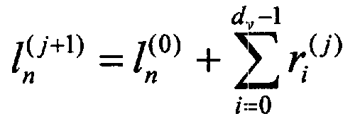
상기 <수학식 4>에서 ![]()
![]()
상기 <수학식 4>와 같이 LLR의 갱신이 이루어지면, 이후 판정(decision) 과정을 수행한다. 상기 판정 과정은 상기 <수학식 4>와 같이 계산된 LLR 갱신 결과에 따라 이루어지며, 모든 코드 심볼에 대하여 수행한다. 이와 같은 판정을 수행하는 방법은 하기 <수학식 5>와 같이 도시할 수 있다.When the LLR is updated as shown in
![]()
![]()
상기 <수학식 5>에서 ![]()
![]()
![]()
![]()
![]()
![]()
상기 <수학식 5>에 도시한 바와 같이 판정을 수행한 이후, 복호된 부호어가 모든 패리티 검사식을 만족하는 경우 반복을 중단한다. 그러나 복호된 부호어가 모든 패리티 검사식을 만족하지 못하는 경우 상기 j 값을 1 증가시킨 후 상기 <수학식 2> 내지 상기 <수학식 5>의 과정을 반복하여 수행한다. 이러한 반복은 미리 반복 횟수를 결정하여 수행하도록 구성할 수 있다. 따라서 미리 결정한 최대 반복 복호의 횟수 이후에도 부호어가 모든 패리티 검사식을 만족하지 않는 경우 복호를 중단하고, 복호 실패를 선언하도록 구성한다.After the determination is performed as shown in
이상의 설명에서 각 노드에서 메시지 갱신(message update)에 사용되는 sum-product 알고리즘을 "최적(optimum)의 sum-product 알고리즘"이라 칭한다. 상기 최적의 sum-product 알고리즘은 어떠한 근사화 과정 없이 이론적인 계산 과정을 통해 쉽게 유도될 수 있다.In the above description, the sum-product algorithm used for message update at each node is referred to as an "optimum sum-product algorithm". The optimal sum-product algorithm can be easily derived through theoretical calculation without any approximation.
그러나 상기 <수학식 2>에 도시한 검사 노드 메시지 갱신 과정은 하기 <수학식 6>과 같이 단순화하여 근사화 할 수 있다. However, the process of updating the check node message shown in

상기 <수학식 6>에서 ![]()
![]()
상기 <수학식 6>은 근사화 과정을 통해 최적의 sum-product 알고리즘에서 검사 노드 메시지 갱신 과정의 계산을 보다 단순화시킨 것이다. 즉, 임의의 검사 노드 m에서 갱신되는 메시지는 검사 노드 m으로 입력되는 임의의 두 가지(edge) 위의 변수 노드 메시지의 부호들을 곱하여 임시 결과 메시지의 부호로 한다. 그리고 상기 변수 노드 메시지들의 절대값 가운데 작은 값을 택하여 임시 결과 메시지의 크기로 정한다. 또한 상기한 근사화 과정으로 인한 오류를 보정하기 위해 미리 정한 규칙에 의해 정해진 교정 값(correction factor, c)을 상기 임시 결과 메시지에 더하여 임시 결과 메시지를 갱신한다. 그리고, 변수 노드 n과 연결되는 가지를 제외한 검사 노드 m으로 입력되는 다른 가지들에 대해 이러한 과정을 반복, 적용하여 검사 노드 메시지를 최종 갱신한다. 이를 이용한 sum-product 알고리즘을 "교정 값을 갖는 sum-product 알고리즘(sum-product algorithm with correction factor)"이라 부르도록 한다. 교정 값을 갖는 sum-product 알고리즘에 의한 LDPC 부호의 반복 복호는 최적의 sum-product 알고리즘에 의한 LDPC 부호의 복호 과정에서 검사 노드 메시지 갱신 과정의 tanh()라는 다소 복잡한 계산을 수행하지 않으면서도, 최적의 sum-product 알고리즘에 의해 얻을 수 있는 복호 성능에 매우 근접하는 우수한 성능을 나타낸다.
전술한 최적의 sum-product 알고리즘은 상기 <수학식 2>에서 알 수 있는 바 와 같이 임의의 반복 복호 시점에서 검사 노드 메시지를 갱신하기 위해서 검사 노드로 입력되는 검사 노드 메시지들에 대해 각각 tanh() 함수 계산을 수행해야 한다. 이는 tanh() 함수의 복잡한 계산식으로 인해 하드웨어 구현 시 복잡도를 증가시킨다. 따라서 이러한 문제점을 해결하기 위해 검사 노드 메시지 업데이트 과정을 근사화 과정을 통해 단순화하고, 이러한 근사화 과정으로 인한 성능 열화를 최소화 하기 위해 근사화 과정에 교정 값을 고려하는 알고리즘이 제안되었다. 그러나, 상기 교정 값을 갖는 sum-product 알고리즘은 검사 노드 메시지를 최종적으로 갱신하기 위해서 검사 노드로 입력되는 모든 가지(edge)들에 대해, 상기 가지로부터 전달되는 변수 노드 메시지에 따라 교정 값을 정하여 주어야 한다. 또 이러한 연산이 모든 가지에 대해 순차적으로 진행되어야 하므로, 각 검사 노드마다 비교적 많은 연산과 시간을 필요로 하게 되는 문제가 있다.
As can be seen from
따라서 본 발명의 목적은 간단한 순방향 오류 정정 부호의 복호 장치 및 방법을 제공함에 있다.It is therefore an object of the present invention to provide a simple apparatus and method for decoding a forward error correcting code.
본 발명의 다른 목적은 sum-product 알고리즘을 사용하는 경우 간단하게 처리할 수 있는 LDPC 복호 장치 및 방법을 제공함에 있다.Another object of the present invention is to provide an LDPC decoding apparatus and method which can be easily processed when using a sum-product algorithm.
본 발명의 다른 목적은 sum-product 알고리즘을 사용하는 경우 각 노드마다의 계산량을 줄일 수 있는 LDPC 복호 장치 및 방법을 제공함에 있다.Another object of the present invention is to provide an LDPC decoding apparatus and method capable of reducing the amount of computation for each node when using the sum-product algorithm.
본 발명의 또 다른 목적은 LDPC 성능을 최대한 유지하면서 계산량을 줄일 수 있는 sum-product 알고리즘을 수행하는 장치 및 그 방법을 제공함에 있다.Another object of the present invention is to provide an apparatus and method for performing a sum-product algorithm that can reduce the amount of computation while maintaining the maximum LDPC performance.
상기한 목적들을 달성하기 위한 본 발명은 저밀도 패리티 검사 코드를 이용하는 통신 시스템에서 순방향 오류 정정 부호를 복호하는 방법에 있어서, 무선 채널을 통해 수신된 부호 비트들이 영(zero)일 확률과 일일 확률의 비로 나타나는 로그 우드율(LLR) 값으로 변환된 값을 변수 노드들의 초기 메시지의 값으로 설정하는 과정과, 각 변수 노드로 입력된 메시지를 상기 각 변수 노드와 연결된 각 검사 노드로 전달하는 전달 과정과, 상기 각 검사 노드가 자신과 연결된 변수 노드들로부터 전달된 메시지들 중 절대값이 최소인 값을 가지는 메시지를 검사하고, 갱신된 메시지를 전달할 변수 노드로부터 전달된 메시지를 제외한 다른 메시지들의 부호의 곱을 계산하여 상기 최소인 값을 가지는 메시지의 부호로 결정하고, 상기 결정된 부호와 상기 최소인 값을 가지는 메시지를 상기 갱신된 메시지로 구하는 검사 노드 갱신 과정과, 상기 각 변수 노드가 자신과 연결된 검사 노드들로부터 각각 상기 갱신된 메시지를 수신하고, 상기 수신된 갱신된 메시지들의 각 부호와 상기 초기 메시지의 부호가 모두 동일할 경우 1의 가중치를 적용하고, 적어도 하나의 부호가 동일하지 않은 경우 1보다 작은 미리 설정된 값의 가중치를 상기 갱신된 메시지를 전달한 검사 노드를 제외한 다른 모든 검사 노드들로부터 수신된 메시지의 합에 적용한 값과 해당 변수 노드의 상기 초기 메시지의 값을 가산하여 상기 초기 메시지를 갱신하는 변수 노드 갱신 과정과, 상기 각 변수 노드가 자신과 연결된 검사 노드들로부터 수신한 메시지들과 초기 입력된 로그 우도율을 가산하여 로그 우도율을 갱신하는 과정과, 상기 갱신된 로드 우도율값들을 경판정하고, 상기 경판정된 값들을 이용하여 저밀도 패리티 코드 행렬의 패리티 검사를 수행하는 패리티 검사 과정을 포함한다.
또한, 본 발명은 행들과 열들의 저밀도 패리티 검사 행렬들로 상기 열의 수를 가지는 이진 비트들을 부호화하여 무선 채널을 통해 전송된 부호 비트들을 복호화하는 순방향 오류 정정 부호를 복호하는 장치에 있어서, 상기 무선 채널을 통해 수신된 상기 부호 비트들이 영(zero)일 확률과 일일 확률의 비로 나타나는 로그 우도율(LLR) 값으로 변환된 값을 변수 노드들의 초기 메시지의 값으로 설정하고, 입력된 메시지를 자신과 연결된 검사 노드들로 전달한 후, 상기 자신과 연결된 검사 노드들로부터 각각 갱신된 메시지들을 수신하며, 상기 검사 노드들로부터 수신된 갱신된 메시지들의 각 부호와 상기 초기 메시지의 부호가 모두 동일할 경우 1의 가중치를 적용하고, 적어도 하나의 부호가 동일하지 않은 경우 1보다 작은 미리 설정된 값의 가중치를 상기 갱신된 메시지를 전달한 검사 노드를 제외한 다른 모든 검사 노드들로부터 수신된 메시지들의 합에 적용한 값과 해당 변수 노드의 상기 초기 메시지의 값을 가산하여 상기 초기 메시지를 갱신하여 이를 출력하는 변수 노드 메시지 결정 장치와, 자신과 연결된 변수 노드들로부터 전달된 메시지들 중 절대값이 최소인 값을 가지는 메시지를 검사하고, 갱신된 메시지를 전달할 변수 노드로부터 전달된 메시지를 제외한 다른 메시지들의 부호의 곱을 계산하여 상기 최소인 값을 가지는 메시지의 부호로 결정하고, 상기 결정된 부호와 상기 최소인 값을 가지는 메시지를 상기 갱신된 메시지로 구하여 출력하는 검사 노드 메시지 결정 장치와, 상기 각 변수 노드와 연결된 노드들로부터 상기 각 변수 노드로 입력되는 메시지들에 상기 가중치를 곱하고, 상기 가중치를 곱한 값을 가산한 값에 상기 초기 메시지의 값을 더한 값으로 상기 로그 우도율 값을 갱신하여 출력하는 로그 우도율 결정기와, 상기 로그 우도율 결정기의 출력 값을 영(zero) 또는 일의 값의 이진수로 복호하여 경판정을 수행하는 경판정 장치와, 상기 경판정 된 값들을 이용하여 저밀도 패리티 검사 코드 행렬의 패리티 검사를 수행하는 패리티 검사 장치를 포함한다.The present invention for achieving the above object is a method of decoding a forward error correction code in a communication system using a low density parity check code, the ratio of the probability that the code bits received over the radio channel is zero (zero) and the daily probability Setting a value converted into a log wood rate (LLR) value to be displayed as a value of an initial message of variable nodes, delivering a message input to each variable node to each inspection node connected to each variable node, Each check node examines a message having a minimum absolute value among messages transmitted from variable nodes connected to the check node, and calculates a product of signs of other messages except for a message transmitted from a variable node to which the updated message is to be delivered. By determining the sign of the message having the minimum value, and the determined sign and the minimum value A check node update process of obtaining a message as an updated message, and each variable node receives the updated message from check nodes connected to the variable node, and each of the symbols of the received updated messages and A message received from all other check nodes except for the check node that delivered the updated message with a weight of a preset value less than 1 if all of the signs are equal and a weight of 1 if at least one sign is not equal. A variable node update process of updating the initial message by adding a value applied to the sum of the initial message of the variable node, a message received from each of the check nodes connected to each variable node, and an initial input value; Updating the log likelihood ratio by adding a log likelihood ratio and updating the updated load likelihood ratio. Establish the yulgap hard decision, using the hard decision value includes a parity check step of performing a parity check matrix for low density parity code.
The present invention also provides an apparatus for decoding a forward error correction code for decoding code bits transmitted over a wireless channel by encoding binary bits having the number of columns into low density parity check matrices of rows and columns. Set the value converted from the log likelihood ratio (LLR) value represented by the ratio of zero probability and daily probability to the value of the initial message of the variable nodes, and the input message is connected to itself. After passing to check nodes, each node receives updated messages from the check nodes connected to the check nodes, and a weight of 1 if each sign of the updated messages received from the check nodes and the sign of the initial message are the same. If the at least one sign is not the same, the weight of the preset value less than 1 A variable node message determination device for updating the initial message by adding a value applied to the sum of messages received from all other inspection nodes except the inspection node that delivered the updated message and the value of the initial message of the corresponding variable node, and outputting the same; Examines a message having a minimum absolute value among messages transmitted from variable nodes connected to the node, and calculates a product of signs of other messages except for a message transmitted from a variable node to which an updated message is to be delivered. A check node message determining device which determines a sign of a message having a value and obtains and outputs a message having the determined sign and the minimum value as the updated message; and each variable node from nodes connected to the variable node. Multiply the messages input by the weight and A log likelihood rate determiner which updates the log likelihood rate value by adding the value multiplied by the value and adds the value of the initial message, and outputs the output value of the log likelihood rate determiner to zero or one day. And a hard decision apparatus for performing hard decision by decoding with a binary number, and a parity check apparatus for performing parity check of a low density parity check code matrix using the hard determined values.
삭제delete
삭제delete
삭제delete
삭제delete
이하 본 발명의 바람직한 실시 예를 첨부한 도면을 참조하여 상세히 설명한다. 우선 각 도면의 구성 요소들에 참조 부호를 부가함에 있어서, 동일한 구성 요 소들에 한해서는 비록 다른 도면상에 표시되더라도 가능한 한 동일한 부호를 가지도록 하고 있음에 유의해야 한다.Hereinafter, exemplary embodiments of the present invention will be described in detail with reference to the accompanying drawings. First of all, in adding reference numerals to the components of each drawing, it should be noted that the same reference numerals have the same reference numerals as much as possible even if displayed on different drawings.
또한 하기 설명에서는 구체적인 장치 또는 프로세서 등과 같은 많은 특정(特定) 사항들이 나타나고 있는데, 이는 본 발명의 보다 전반적인 이해를 돕기 위해서 제공된 것일 뿐 이러한 특정 사항들 없이도 본 발명이 실시될 수 있음은 이 기술 분야에서 통상의 지식을 가진 자에게는 자명하다 할 것이다. 그리고 본 발명을 설명함에 있어, 관련된 공지 기능 혹은 구성에 대한 구체적인 설명이 본 발명의 요지를 불필요하게 흐릴 수 있다고 판단되는 경우 그 상세한 설명을 생략한다.In addition, in the following description, many specific details such as a specific apparatus or a processor, etc. are shown, which are provided to help a more general understanding of the present invention, and it is understood that the present invention may be practiced without these specific details. It will be self-evident to those of ordinary knowledge. In the following description of the present invention, if it is determined that a detailed description of a related known function or configuration may unnecessarily obscure the subject matter of the present invention, the detailed description thereof will be omitted.
본 발명은 LDPC 코드를 사용하는 복호 시에 사용되는 sum-product 알고리즘을 수정하였다. 이하의 설명에서 본 발명에 따라 LDPC 코드의 복호 알고리즘을 "수정 sum-product 알고리즘"이라 칭한다.The present invention modified the sum-product algorithm used in decoding using LDPC code. In the following description, the decoding algorithm of the LDPC code is called a "modified sum-product algorithm" according to the present invention.
본 발명에 따른 수정 sum-product 알고리즘은 종래기술에서 설명한 검사 노드 메시지 갱신 과정인 <수학식 2>를 하기 <수학식 7>과 같이 변경한다.In the modified sum-product algorithm according to the present invention,

상기 <수학식 7>은 교정 값을 갖는 sum-product 알고리즘의 검사 노드 메시지 갱신 과정에서 교정 값을 고려하지 않는 식이다. 상기 <수학식 7>과 같이 검사 노드 메시지 갱신이 수정되면, 종래기술에서 변수 노드 메시지 갱신 과정으로 상술한 <수학식 3>은 본 발명에서 하기 <수학식 8>과 같이 변경된다.
Equation 7 does not consider the calibration value in the process of updating the check node message of the sum-product algorithm having the calibration value. When the check node message update is modified as shown in Equation 7,

상기 <수학식 8>에서 sgn(x)함수는 x값의 부호를 나타내는 함수로서, x가 0보다 크면 sgn(x)는 1이고, x가 0보다 작으면 sgn(x)는 -1이 된다. 그리고, ![]()
![]()
![]()
![]()
상술한 바와 같이 상기 <수학식 7> 및 <수학식 8>과 같은 계산에 따르면 LLR의 갱신 과정은 종래기술에서 상술한 <수학식 4>가 하기 <수학식 9>와 같이 변경된다.As described above, according to the calculations shown in Equations 7 and 8, the updating process of the LLR is changed from

상기 <수학식 8>과 상기 <수학식 9>의 가중치를 통해 존재 가능한 짧은 순환으로 인한 자가-정보(self-information)의 영향을 감쇄시켜 성능 개선을 기대할 수 있다.Through the weights of Equations 8 and 9, the effect of self-information due to a short cycle that can exist can be expected to improve performance.
이때, 임의의 변수 노드로 입력되는 검사 노드 메시지와 채널 신뢰도는 각각 해당 변수 노드가 '0'또는 '1'의 값을 가질 확률을 나타내므로, 이들의 부호가 동일하지 않으면 전송로에서, 또는 복호 과정에서 오류가 발생되었다고 간주할 수 있다. 따라서 이러한 경우 상기 메시지들을 통해 얻게 되는 변수 노드 메시지나 LLR은, 변수 노드로 입력되는 모든 메시지들의 부호가 동일한 경우 얻게 되는 변수 노드 메시지나 LLR에 비해 신뢰도가 떨어진다고 볼 수 있다. 그러므로 변수 노드로 입력되는 모든 메시지들의 부호가 동일하지 않으면 해당 변수 노드 메시지와 LLR값에 1보다 작은 가중치를 곱한다. 또한 상기 가중치의 값은 실험을 통해 적절한 값으로 설정할 수 있다.At this time, the check node message and channel reliability input to an arbitrary variable node represent the probability that the corresponding variable node has a value of '0' or '1'. You can assume that an error has occurred in the process. Therefore, in this case, the variable node message or the LLR obtained through the messages may be considered to be less reliable than the variable node message or the LLR obtained when all the messages input to the variable node have the same sign. Therefore, if all of the messages entered into the variable node do not have the same sign, the variable node message and the LLR value are multiplied by a weight less than one. In addition, the weight value may be set to an appropriate value through experimentation.
이하의 설명에서 상술한 바와 같이 적응형 가중치를 고려한 수정 sum-product 알고리즘을 "가중치를 갖는 수정 sum-product 알고리즘(sum-product algorithm with weighting)"이라 칭한다.As described above in the following description, the modified sum-product algorithm considering the adaptive weight is referred to as a "sum-product algorithm with weighting".
도 2는 본 발명에 따라 LDPC 부호의 반복 복호 시 가중치를 갖는 수정 sum-product 알고리즘에 따른 제어 흐름도이다. 이하 도 2를 참조하여 본 발명에 따른 LDPC 부호의 반복 복호 시 가중치를 갖는 수정 sum-product 알고리즘에 따른 제어 과정을 상세히 설명한다.2 is a control flowchart according to a modified sum-product algorithm having weights for iterative decoding of LDPC codes according to the present invention. Hereinafter, a control process according to a modified sum-product algorithm having a weight during iterative decoding of an LDPC code according to the present invention will be described in detail with reference to FIG. 2.
200단계는 초기화 과정을 도시하였다. 초기화 과정에서는 LDPC code 구조를 나타내는 펙터 그래프(factor graph)의 변수 노드 메시지의 초기 값을 설정한다. 상기 변수 노드 메시지의 초기 값은 해당 변수 노드에 대응하는 수신 code 심볼에 대한 채널 신뢰도로 한다. 이때, 가중치를 갖는 수정 sum-product 알고리즘은 LLR 도메인(domain)에서의 연산을 수행하므로, 채널 신뢰도는 수신 심볼에 신호 대 잡음비(SNR)를 곱한 형태이다. 이에 따라 펙터 그래프(Factor graph)상의 모든 변수 노드에 대해 메시지 초기화를 수행한다.Step 200 shows the initialization process. In the initialization process, the initial value of the variable node message of the factor graph representing the LDPC code structure is set. The initial value of the variable node message is a channel reliability for a received code symbol corresponding to the variable node. In this case, since the weighted modified sum-product algorithm performs an operation in the LLR domain, the channel reliability is obtained by multiplying the received symbol by the signal-to-noise ratio (SNR). Accordingly, message initialization is performed for all variable nodes on the factor graph.
상기한 바와 같이 초기화 과정을 수행한 후 202단계로 진행한다. 상기 202단계는 검사 노드 메시지의 갱신 과정이다. 상기 검사 노드 메시지의 갱신 과정은 전술한 <수학식 7>을 이용하여 검사 노드 메시지를 갱신한다. 즉, 변수 노드 n으로 출력되는 검사 노드 메시지의 갱신 과정은, 검사 노드로 입력되는 메시지 가운데 변수 노드 n으로부터의 입력을 제외한 모든 입력 메시지들의 부호를 모두 곱하여 출력 메시지의 부호로 한다. 그리고 상기 입력 메시지들의 절대값 가운데 가장 최소 값을 택하여 출력 메시지의 크기로 한다. 이러한 방식으로 상기 도 1과 같은 펙터 그래프 상의 모든 검사 노드에 대해 메시지 갱신을 수행한다.After performing the initialization process as described above, the process proceeds to step 202. Step 202 is an update process of the check node message. In the updating of the check node message, the check node message is updated by using Equation 7 described above. That is, in the updating process of the check node message output to the variable node n, all of the input messages except for the input from the variable node n among the messages input to the check node are multiplied as the sign of the output message. The minimum value among absolute values of the input messages is selected to be an output message size. In this manner, message updating is performed for all inspection nodes on the factor graph as shown in FIG.
상기 검사 노드 메시지의 갱신이 완료되면, 변수 노드 메시지의 갱신을 수행하는 204단계로 진행한다. 상기 <수학식 8>을 이용하여 변수 노드 메시지를 갱신한다. 즉, 검사 노드 n으로 출력되는 변수 노드 메시지의 업데이트 과정은, 변수 노드로 입력되는 메시지 가운데 검사 노드 m으로부터의 입력을 제외한 모든 입력 메시지들에 가중치를 곱하고, 이 값들을 가산한다. 그리고, 변수 노드 메시지의 초기 값인 채널 신뢰도를 더하여 이루어진다. 이때, 변수 노드로 입력되는 모든 메시지의 부호와 채널 신뢰도의 부호가 모두 동일하면 가중치는 1이고, 그렇지 않으면 가중치는 1보다 작은 값이 된다. 상기 변수 노드 메시지의 갱신 과정인 204단계에서도 상기 도 1과 같은 형태의 펙터 그래프 상의 모든 변수 노드에 대해 메시지 업데이트를 수행한다.When the check node message is updated, the process proceeds to step 204 in which the variable node message is updated. The variable node message is updated using Equation (8). That is, the updating process of the variable node message output to the check node n multiplies the weights of all input messages except the input from the check node m among the messages input to the variable node, and adds these values. The channel reliability, which is an initial value of the variable node message, is added. At this time, if the sign of all the messages input to the variable node and the sign of the channel reliability is the same, the weight is 1, otherwise the weight is less than 1. In
그런 후 LLR 갱신을 위해 206단계로 진행한다. 206단계로 진행하면, 상기 <수학식 9>를 이용하여 변수 노드에 해당하는 code 심볼에 대한 LLR 값을 갱신한다. LLR 갱신 과정은 변수 노드로 입력되는 모든 메시지에 가중치를 곱하고, 이를 가산한 값에 변수 노드 메시지의 초기 값인 채널 신뢰도를 더한 값이다. 이때, 가중치의 값은 상기 204단계에서와 동일한 방식에 의해 정해진다. LLR 갱신 과정 또한 펙터 그래프 상의 모든 code 심볼에 대한 LLR 업데이트를 수행한다.
Then proceed to step 206 to update the LLR. In
이후 208단계로 진행하여 경판정(hard decision) 과정을 수행한다. 상기 경판정 과정은 LDPC 부호의 임의의 한 심볼에서 LLR 값이 0보다 크면 이진수 '0'을 복호하고, LLR 값이 0보다 작으면 이진수 '1'을 복호하여 이 값을 저장한다. 하나의 LDPC 부호어(codeword)를 이루는 모든 code 심볼에 대해 경판정을 수행하고, 복호된 부호어를 얻는다. 이와 같이 경판정을 수행한 후 210단계로 진행한다.In
상기 210단계 및 214단계는 패리티 검사를 통해 오류가 발생하였는가를 검사하는 과정이다. 상기 LDPC 부호의 모든 code 심볼에 대한 경판정이 완료되면 이들로부터 하나의 부호어(codeword)를 얻을 수 있게 된다. 상기 얻어진 부호어에 대하여 패리티 검사 행렬에 의해 정의되는 모든 패리티 검사식을 적용하여 오류가 검출되지 않으면 212단계로 진행하여 복호를 중지한다. 그리고 해당 부호어를 복호 완료된 부호어로 저장한다. 반면에 상기 210단계의 검사결과 오류가 발생하면 214단계로 진행하여 미리 설정된 최대 횟수만큼 수행하였는가를 검사한다. 상기 검사결과 미리 설정된 횟수만큼 수행하지 않은 경우 218단계로 진행하여 복호 회수를 1만큼 증가시킨 후 202단계로 진행하여 반복 복호를 계속 수행한다. 그러나 상기 214단계의 검사결과 미리 설정한 횟수만큼 반복 복호의 과정을 거친 후에도 오류가 계속 검출되면 216단계로 진행하여 복호를 중지한다. 그리고, 복호 실패(decoding failure)를 선언하고, 해당 부호어는 버린다.
도 3a는 본 발명의 실시 바람직한 예에 따라 임의의 검사 노드에서 메시지의 갱신 시 제어 흐름도이다. 이하 도 3a를 참조하여 임의의 검사 노드에서 메시 갱신 시 제어 과정을 상세히 설명한다. 3A is a control flow diagram when updating a message at any check node in accordance with an embodiment of the present invention. Hereinafter, referring to FIG. 3A, a control process for updating a mesh in an arbitrary inspection node will be described in detail.
상기 300단계는 임의의 변수 노드로부터 임의의 검사 노드로 입력되는 메시지들을 재 정렬하는 단계이다. 즉, 임의의 검사 노드 m으로 입력되는 메시지 가운데 변수 노드 n으로부터 입력되는 메시지의 인덱스를 새로운 메시지 인덱스 i의 최초 인덱스 (i=0)로 할당한다. 302단계는 검사 노드로 입력되는 메시지 가운데 메시지 인덱스 i가 0인 경우를 제외한 모든 메시지의 절대값을 비교하여 그 가운데 최소 값을 찾는 단계이다. 이와 같이 최소 값을 갖는 메시지 인덱스를 찾은 후 304단계로 진행한다. 상기 304단계는 검사 노드로 입력되는 메시지 가운데 메시지 인덱스 i가 0인 경우를 제외한 모든 메시지의 부호를 곱하는 단계이다. 그리고 상기 306단계로 진행한다. 상기 306단계는 상기 302단계에서 구한 메시지 절대값의 최소값 과, 상기 304단계로부터 구한 메시지 부호를 곱하여 최종 메시지, 즉 임의의 검사노드 m으로부터 임의의 변수 노드 n으로 전달되는 메시지를 구하는 단계이다. 결과적으로 도 3a는 상기 <수학식 7>을 구하는 과정을 도시한 것이다.Step 300 is to rearrange the messages input from any variable node to any check node. That is, the index of the message input from the variable node n among the messages input to the arbitrary check node m is assigned as the first index (i = 0) of the new message index i. In
도 3b는 본 발명의 바람직한 실시 예에 따라 상기 도 3a의 과정을 수행하는 검사 노드와 연결된 변수 노드에서 메시지 갱신 시의 제어 흐름도이다. 이하 도 3a 및 도 3b를 참조하여 본 발명에 따라 소정 검사 노드와 연결된 변수 노드에서 메시지 갱신 시의 제어 과정을 상세히 설명한다.FIG. 3B is a control flowchart of updating a message in a variable node connected to an inspection node performing the process of FIG. 3A according to an exemplary embodiment of the present invention. 3A and 3B, a control process for updating a message in a variable node connected to a predetermined check node according to the present invention will be described in detail.
상기 310단계는 임의의 검사 노드로부터 임의의 변수 노드로 입력되는 메시지를 재 정렬하는 과정이다. 즉, 임의의 변수 노드 n으로 입력되는 메시지 가운데 검사 노드 m으로부터 입력되는 메시지의 인덱스를 새로운 메시지 인덱스 i의 최초 인덱스 (i=0)로 할당한다. 그런 후 312단계로 진행한다. 상기 312단계는 임의의 변수 노드로 입력되는 모든 메시지의 부호와, 상기 변수 노드에 대한 초기 메시지 값의 부호를 더하여 임의의 변수 s를 구하는 단계이다. 이와 같이 임의의 변수를 구한 후 314단계로 진행한다. 상기 314단계는 상기 312단계에서 구한 s의 절대값을 변수 노드로 입력되는 모든 메시지의 수에 1을 더한 값과 비교한다. 상기 비교 결과 s의 절대값이 변수 노드 입력 메시지의 수에 1을 더한 값과 일치하면, 316단계로 진행하고, 그렇지 않은 경우 318단계로 진행한다. 여기서 상기 s의 절대값이 변수 노드 입력 메시지의 수에 1을 더한 값과 일치하는가를 검사하는 것은 변수 노드로부터 입력되는 모든 메시지 및 변수 노드 메시지의 초기 값의 부호가 모두 일치하는가를 검사하는 것이다. 이와 같은 검사 결과 변수 노드로 입력되는 모든 메시지 및 변수 노드 메시지의 초기 값의 부호가 모두 일치하여 316단계로 진행하면 상기 변수 노드에 대한 가중치의 값을 1로 설정한다. 그러나 s의 절대값이 변수 노드 입력 메시지의 수에 1을 더한 값과 일치하지 않으면, 즉 변수 노드로 입력되는 모든 메시지 및 변수 노드 메시지의 초기 값의 부호가 하나라도 불일치하면, 318단계로 진행하여 상기 변수 노드에 대한 가중치의 값을 미리 설정한 1보다 작은 값으로 설정한다. 그런 후 316단계 또는 318단계를 수행한 후 320단계로 진행한다. 상기 320단계는 316단계 또는 318단계에서 구한 가중치와, 임의의 변수 노드에 대한 초기 메시지와, 임의의 변수 노드로 입력되는 검사 노드 메시지 가운데 메시지 인덱스 i가 0인 경우를 제외한 모든 메시지들의 합을 이용하여 임의의 변수 노드 n으로부터 임의의 검사 노드 m으로 전달되는 메시지를 구한다. 그리고 322단계로 진행한다. 상기 322단계는 상기 316단계 또는 상기 318단계로부터 구한 가중치와, 임의의 변수 노드에 대한 초기 LLR 메시지와, 임의의 변수 노드로 입력되는 모든 검사 노드 메시지들의 합을 이용하여 임의의 변수 노드 n에 대한 LLR 메시지를 구한다.Step 310 is a process of rearranging messages input from any check node to any variable node. That is, the index of the message input from the check node m among the messages input to the arbitrary variable node n is assigned as the first index (i = 0) of the new message index i. Then proceed to step 312. Step 312 is a step of obtaining a random variable s by adding a sign of all messages input to a random variable node and a sign of an initial message value for the variable node. After the random variables are obtained, the process proceeds to step 314. In
이하에서 본 발명에 따른 각 노드에서의 메시지 갱신을 위한 프로세서의 구현 실시 예를 살피기로 한다. 우선 간단한 구현 실시 예를 위해 임의의 검사 노드와 변수 노드의 입력 가지 수는 각각 3개로 가정한다. 이에 대한 임의의 검사 노드 m과 변수 노드 n에서의 메시지 갱신을 도면으로 도시하면 각각 도 4a 및 도 4b와 같이 도시할 수 있다. 또한 상기 도 4a 및 도 4b에 도시된 바와 같이 구성될 경우 각 노드에 대한 프로세서를 도면으로 도시하면 각각 도 5a와 도 5b로 도시할 수 있다.Hereinafter, an embodiment of a processor for updating a message in each node according to the present invention will be described. First, it is assumed that the number of input branches of an arbitrary check node and a variable node is three for a simple implementation. The message update at any check node m and variable node n for this can be illustrated in Figs. 4A and 4B, respectively. 4A and 4B, the processor for each node may be illustrated in FIGS. 5A and 5B, respectively.
상기 도 5a 및 도 5b에 도시한 도면은 각 node로의 입력 가지 수를 항상 3으로 가정하였으므로, 검사 노드 프로세서의 입출력 포트(port)의 수는 각각 3이고, 변수 노드 프로세서의 입출력 포트(port) 수는 LLR을 고려하여 각각 4개이다. 실제의 정규 LDPC code에 대한 각 노드 프로세서의 입출력 포트(port) 수는 각 노드의 입력 가지 수인 ![]()
![]()
![]()
![]()
상기 도 5a는 입력 변수 노드 메시지를 가공하여 검사 노드 메시지를 구하는 상기 <수학식 7>을 구현한 하드웨어 장치의 예이다. 상기 도 5a의 절대값 계산 장치들(500)은 입력 변수 노드 메시지의 절대값을 구한다. 그리고 입력 변수 계산 장치(502)는 입력 변수 노드 메시지의 부호를 구하는 장치들이다. 상기 절대값 계산 장치(500)에서 계산된 각 절대값들은 최소 값 선택 장치들(504)로 입력되어 두 개의 입력에 대한 최소 값을 선택한다. 곱셈 장치들(506)은 두 개의 입력 값을 곱한 값을 구하는 곱셈기 장치들이다. 먼저 입력 변수 계산장치들(502)에서 출력된 값들은 2개씩 쌍으로 구성되어 3개의 곱셈 장치들(506)로 입력된다. 여기서 입력 변수 계산장치들(502)로부터의 값을 쌍으로 계산하는 곱셈 장치들(506)이 3개로 구성된 것은 검사 노드로 입력되는 가지가 3개인 것으로 가정하였기 때문이다. 이와 같이 상기 입력 변수 계산장치들(502)로부터의 출력 값을 2개씩 쌍으로 구성하여 곱셈을 수행한 3개의 곱셈 장치들의 출력과 상기 최소 값 선택 장치들(504)의 출력신호들은 다시 3개의 곱셈 장치들(506)로 입력된다. 이와 같이 3개의 곱셈 장치들(503)은 입력된 두 값을 곱해서 각 변수 노드들로 전송할 값들(rm0, rm1, rm2)을 생성한다.5A illustrates an example of a hardware device that implements Equation 7 to process an input variable node message to obtain a check node message. The absolute
상기 도 5b는 입력 검사 노드 메시지와 LLR 메시지를 가공하여 변수 노드 메시지와 새로운 LLR 메시지를 구하는 상기 <수학식 8> 및 상기 <수학식 9>를 구현한 하드웨어 장치의 예이다. 상기 도 5b의 앞단에 구비된 3개의 가산기 장치들(510)은 각 검사 노드로부터의 입력 중 2개씩 쌍으로 구성되어 입력되는 입력을 더하여 출력한다. 또한 4개의 부호 검출 장치들(512)은 입력 검사 노드 메시지와 최초 입력되는 채널의 신뢰도에 따른 LLR값의 부호를 계산하여 출력한다. 상기 부호 검출 장치들(512)의 출력은 가산 장치(514)로 입력된다. 상기 가산 장치(514)는 각 입력 신호들을 더하여 출력한다. 그리고 상기 가산 장치(514)에서 계산된 값은 절대값 계산 장치(516)로 입력된다. 그러면 절대값 계산 장치(516)는 상기 입력된 값의 절대값을 계산하여 출력한다. 상기 절대값 계산 장치(516)의 출력과 고정된 임의의 값을 입력으로 하는 비교 장치(518)는 두 개의 입력에 대하여, 두 입력 값이 서로 같으면 '1'의 값을, 그렇지 않으면 '0'의 값을 출력한다. 상기 출력된 값은 선택 장치(520)의 제어 신호로 입력된다. 상기 선택 장치(520)는 선택 신호의 값 - 0 또는 1- 에 따라 두 개의 입력(1 또는 fg) 중 하나를 선택하여 출력한다. 또한 4개의 곱셈 장치들(522)은 먼저 상기 검사 노드로부터 수신된 값을 쌍으로 가산한 3개의 가산기들(510)의 출력들을 입력으로 가지는 곱셈기들이 있다. 또한 상기 검사 노드로부터 수신되는 신호 중 첫 번째 검사노드로부터 수신되는 신호를 입력으로 가지는 곱셈기가 구비된다. 이와 같이 곱셈기들은 총 4개로 구성된다. 상기 4개의 모든 곱셈기들(522)은 상기 선택 장치(520)의 출력을 다른 입력으로 가진다. 따라서 상기 각 곱셈기들(522)은 입력된 두 신호의 곱을 계산하여 출력한다. 이와 같이 출력된 값들은 각 가산 장치들(510)로 입력되어 가산된 값을 출력한다. 또한 상기 가산장치들(510) 또한 4개로 구성되는데, 가산되는 값은 서로 다른 값을 가지고 가산이 이루어진다. 이를 상술하면, 3개의 가산기들은 앞에서 상술한 3개의 곱셈기의 각 출력을 하나의 입력으로 한다. 그리고 상기 3개의 가산기들의 다른 입력은 수신 부호어의 채널 신뢰도로 정의되는 초기 값을 다른 입력으로 한다. 상기 3개의 가산기들은 이와 같은 각 입력들을 각각 가산하여 출력한다. 또한 상기 다른 하나의 곱셈기의 출력을 입력으로 하는 가산기는 제1검사 노드로 출력되는 신호를 다른 입력으로 한다. 따라서 제1검사 노드로 입력되는 신호와 상기 곱셈기의 출력을 가산하여 LLR 값을 결정하기 위한 출력으로 한다. FIG. 5B is an example of a hardware device that implements Equations 8 and 9 by processing an input check node message and an LLR message to obtain a variable node message and a new LLR message. The three
그러면 상술한 바와 같이 구성하여 LDPC 코드를 복호할 경우 모의 실험 결과에 대하여 살펴본다. 상기 모의 실험은 2가지 경우로 구분하였다. 첫째로, 길이가 짧은 LDPC 부호에 대한 모의 실험과, 둘째로, 길이가 긴 LDPC 부호에 대한 모의 실험으로 구분된다. Next, the simulation result when the LDPC code is decoded as described above will be described. The simulation was divided into two cases. First, it is divided into simulations for short length LDPC codes and second, simulations for long length LDPC codes.
그러면 먼저 길이가 짧은 LDPC 부호에 대한 모의 실험에 대하여 살펴본다. 우선 실험 환경은 하기와 같이 구성한다.First, the simulation of the short LDPC code will be described. First, the experimental environment is configured as follows.
(1) 펙터 그래프(Factor graph) 상에서 검사 노드로 입력되는 가지(edge)의 수가 6개로 항상 일정하고, 변수 노드로 입력되는 가지의 수가 3개로 항상 일정한 정규 LDPC code를 사용한다. 그리고, 길이가 6보다 작은 짧은 순환(short cycle)은 펙터 그래프(factor graph) 생성 과정에서 제거한다.(1) The regular LDPC code is always used, where the number of edges input to the test node is always constant on the factor graph and the number of edges input to the variable node is three. Short cycles of length less than six are removed during factor graph generation.
(2) 검사 노드의 수는 252개, 변수 노드의 수는 504개로 한다.(2) The number of inspection nodes shall be 252, and the number of variable nodes shall be 504.
(3) 모의 실험상에서 LDPC 부호를 생성하는 모든 정보 bit는 모두 '0'으로 가정한다. 따라서 전송되는 LDPC 부호어 심볼 또한 모두 '0'으로 가정하였다. LDPC 부호는 선형 부호(linear code)이므로, 이러한 실험에 의해 얻는 결과는 일반성을 잃지 않는다. (3) In simulation, all information bits for generating LDPC code are assumed to be '0'. Therefore, all transmitted LDPC codeword symbols are also assumed to be '0'. Since the LDPC code is a linear code, the results obtained by these experiments do not lose their generality.
(4) BPSK 복조 방식 및 채널 환경은 AWGN 전송로로 가정한다.(4) The BPSK demodulation method and channel environment are assumed to be AWGN transmission paths.
(5) 최대 반복 복호에 이르지 않고 복호 완료된 부호어는 항상 오류가 없다고 가정한다. 즉, Undetected error 확률은 0이라 가정한다.(5) It is assumed that codewords which have not been decoded to the maximum iterative decoding always have no error. In other words, the probability of Undetected error is assumed to be zero.
(6) 변수 노드 메시지 갱신 과정의 1보다 작은 가중치는 ![]()
![]()
(7) 복호 성능 기준은 정보 bit 당 energy (Eb/No)에 대한 부호어 오류 확률(Word error rate, WER)로 설정한다.(7) The decoding performance criterion is set to a word error rate (WER) for energy (Eb / No) per information bit.
(8) 최대 반복 복호 회수는 50회 및 200회로 설정한다.(8) The maximum number of times of repeated decoding is set to 50 times and 200 times.
상기한 바와 같은 조건 하에서 실험한 결과는 도 6과 같이 도시된다. 도 6은 최대 반복횟수를 50회로 설정하였을 경우 길이가 짧은 LDPC 부호의 복호를 본 발명에 따른 방법과, 종래의 방법 및 최적의 방법 사용 시 부호어의 오류 확률을 비교한 그래프이다.The results of the experiment under the above conditions are shown in FIG. 6. 6 is a graph comparing the error probability of a codeword in the method according to the present invention with the decoding of an LDPC code having a short length when the maximum number of repetitions is set to 50 times.
상기 도 6에서 'opt'는 최적의 sum-product 알고리즘에 의한 복호 성능을 나타내며, 'with corr.'는 교정 값을 갖는 sum-product 알고리즘에 의한 복호 성능을 나타내고, 'with weight'는 본 발명에서 제안하는 가중치를 갖는 수정 sum-product 알고리즘에 의한 복호 성능을 나타낸다. 상기 도 6에서 보듯이 높은 신호 대 잡음비에서 본 발명에서 제안하는 가중치를 갖는 sum-product 알고리즘에 의한 복호 성능이 가장 우수한 WER 성능을 보이고 있음을 알 수 있다. 이는 길이가 짧은 LDPC 부호의 경우, 랜덤하게 정의된 펙터 그래프 상에 짧은 순환들이 존재할 확률이 높고, 이에 따라 궤환되는 자가-정보(self-information)에 의한 영향이 복호 성능에 나쁜 영향을 미치는 경우가 많아지기 때문이다. 일반적으로 펙터 그래프 상의 순환에 의한 영향은 길이가 짧은 LDPC 부호에서는 짧은 순환의 발생 확률이 높고, 이에 따라 복호 성능의 열화를 발생시킬 확률 또한 높아지게 된다. 반면, LDPC 부호의 길이가 길어질수록, 짧은 순환의 발생 확률이 줄어들기 때문에 그 영향은 점차 감소하게 되는 것으로 알려져 있다. 그리고, 짧은 순환이 존재한다 하더라도 반복 복호 회수를 증가시키면 이에 의한 복호 성능의 영향은 또한 감소하는 것으로 알려져 있다.In FIG. 6, 'opt' denotes decoding performance by an optimal sum-product algorithm, 'with corr.' Denotes decoding performance by a sum-product algorithm having a correction value, and 'with weight' denotes by the present invention. It shows the decoding performance by the modified sum-product algorithm with the proposed weights. As shown in FIG. 6, it can be seen that the decoding performance by the sum-product algorithm having the weight proposed by the present invention at the high signal-to-noise ratio shows the best WER performance. This is because, for short LDPC codes, there is a high probability that there will be short cycles on a randomly defined factor graph, whereby the influence of feedback self-information adversely affects the decoding performance. Because it increases. In general, the influence of the cycle on the factor graph has a high probability of occurrence of a short cycle in an LDPC code with a short length, thereby increasing the probability of causing deterioration in decoding performance. On the other hand, the longer the length of the LDPC code, the smaller the probability of occurrence of a short cycle is known that its effect is gradually reduced. And even if there is a short cycle, it is known that increasing the number of iterative decoding decreases the effect of the decoding performance thereby.
본 발명에서 제안한 가중치를 갖는 수정 sum-product 알고리즘은 변수 노드 메시지 갱신 과정에서 1보다 작은 가중치를 고려하고, 이 가중치에 의해 펙터 그래 프 상에 존재하는 짧은 순환에 의해 궤환되는 자가-정보(self-information)의 영향을 줄일 수 있기 때문에 가장 우수한 성능을 나타내는 것으로 보인다. 따라서, 가중치를 갖는 수정 sum-product 알고리즘은 길이가 짧고, 랜덤하게 생성한 정규 LDPC 부호의 복호에 있어 연산 복잡도(computational complexity)가 낮으면서도 가장 우수한 WER 성능을 보이고 있음을 확인할 수 있었다.The weighted modified sum-product algorithm proposed in the present invention considers a weight less than 1 in the process of updating a variable node message, and the weighted self-information is fed back by a short cycle existing on the factor graph. It seems to have the best performance because it can reduce the influence of information. Therefore, the modified sum-product algorithm with weights shows the best WER performance with short computational complexity and low computational complexity in the decoding of randomly generated regular LDPC codes.
도 7은 최대 반복횟수를 200회로 설정하였을 경우 길이가 짧은 LDPC 부호의 복호를 본 발명에 따른 방법과, 종래의 방법 및 최적의 방법 사용 시 부호어의 오류 확률을 비교한 그래프이다.7 is a graph comparing the error probability of a codeword when the maximum repetition frequency is set to 200 times according to the present invention for decoding a short LDPC code and a conventional method and an optimal method.
상기 도 7을 살펴보면 LDPC 부호에 대한 세 가지 방식의 복호 결과에 따른 WER 성능 차이가 최대 반복 회수를 50으로 하였을 때에 비해 감소하여 이들간의 성능 차이가 미미함을 보이고 있음을 알 수 있다. 이는 반복 복호의 회수가 증가하면 LDPC 부호의 짧은 순환에 의한 영향이 감소하기 때문인 것으로 보여진다.Referring to FIG. 7, it can be seen that the WER performance difference according to the decoding results of the three schemes for the LDPC code is reduced compared to when the maximum number of iterations is 50, indicating that the performance difference between them is insignificant. This seems to be because the increase in the number of times of repeated decoding decreases the effect of the short cycle of the LDPC code.
다음으로 길이가 긴 LDPC 부호에 대한 모의 실험에 대하여 살펴본다. 우선 실험 환경은 앞선 실험과 동일하되, LDPC 부호의 검사 노드의 수와 변수 노드의 수를 각각 4986개와 9972개로 증가시켰다. 즉, 임의의 한 LDPC 부호어의 code 심볼의 수를 9972개로 증가시켜 길이가 긴 LDPC 부호에 대한 복호 실험을 수행하였다. 그리고, 가중치를 갖는 sum-product 알고리즘의 변수 노드 메시지 갱신 과정의 1보다 작은 가중치 또한 짧은 LDPC 부호의 실험과 동일하게 설정한다. Next, the simulation of the long LDPC code is described. First, the experimental environment was the same as the previous experiment, but the number of test nodes and variable nodes of LDPC codes were increased to 4986 and 9972, respectively. That is, a decoding experiment on a long LDPC code was performed by increasing the number of code symbols of any one LDPC codeword to 9972. In addition, a weight less than 1 in the variable node message update process of the sum-product algorithm with weights is set to be the same as the experiment of the short LDPC code.
도 8은 최대 반복횟수를 50회로 설정하였을 경우 길이가 긴 LDPC 부호의 복호를 본 발명에 따른 방법과, 종래의 방법 및 최적의 방법 사용 시 부호어의 오류 확률을 비교한 그래프이고, 도 9는 최대 반복횟수를 200회로 설정하였을 경우 길이가 긴 LDPC 부호의 복호를 본 발명에 따른 방법과, 종래의 방법 및 최적의 방법 사용 시 부호어의 오류 확률을 비교한 그래프이다.8 is a graph comparing the error probability of a codeword in the method according to the present invention with the decoding of a long LDPC code when the maximum number of repetitions is set to 50 times, and FIG. 9. When the maximum number of repetitions is set to 200 times, the decoding of a long LDPC code is a graph comparing the error probability of the codeword with the method according to the present invention and the conventional method and the optimal method.
상기 길이가 긴 LDPC 부호는 길이가 짧은 LDPC 부호에 비해 펙터 그래프 상에서 짧은 순환이 발생할 확률이 줄어들기 때문에, 짧은 순환이 성능에 미치는 영향은 길이가 짧은 LDPC 부호에 비해 미미하다고 알려져 있다. 따라서, 길이가 긴 LDPC부호의 경우에는 도 8에서와 같이 최적의 sum-product 알고리즘에 의한 복호 성능이 가장 우수한 것을 알 수 있다. 그리고, 최적의 sum-product 알고리즘과 유사한, 교정 값을 갖는 sum-product 알고리즘에 의한 복호 성능이 그 다음으로 우수하고, 본 발명에서 제안하는 가중치를 갖는 수정 sum-product 알고리즘에 의한 복호 성능이 가장 좋지 않은 것으로 확인되었다. 이는 본 발명에서 제안하는 가중치가 짧은 순환에 의한 자가-정보(self-information) 뿐 아니라, 올바른 정보까지도 감쇄시키는 영향이 있기 때문이다. 이는 짧은 LDPC 부호에서는 그리 문제가 되지 않았으나, 길이가 긴 LDPC 부호에서는 복호 성능의 열화로 나타나기 때문이다. 그러나 도 8에서 보듯이 가중치를 갖는 sum-product 알고리즘에 의한 성능 열화는 매우 미미하여, ![]()
Since the long LDPC code is less likely to generate a short cycle on the factor graph compared to the short LDPC code, the effect of the short cycle on the performance is known to be insignificant compared to the short LDPC code. Therefore, in the case of the long LDPC code, it can be seen that the decoding performance by the optimal sum-product algorithm is the best as shown in FIG. 8. Then, the decoding performance by the sum-product algorithm having a calibration value similar to the optimal sum-product algorithm is next superior, and the decoding performance by the modified sum-product algorithm with weights proposed by the present invention is the best. Was confirmed. This is because not only self-information by the short weight cycle proposed in the present invention but also attenuates correct information. This is not a problem for short LDPC codes, but for long LDPC codes, it appears as a degradation of decoding performance. However, as shown in FIG. 8, the performance degradation by the weighted sum-product algorithm is very slight. ![]()
상술한 바와 같이 본 발명에서 제안한 수정 sum-product 알고리즘의 사용으로 인해 복호 과정의 연산 복잡도(computational complexity)를 감소시킬 수 있는 이점이 있다. 또한 최적의 sum-product 알고리즘을 사용하여 얻을 수 있는 복호 성능보다 우수하거나, 이에 근접하는 성능을 얻을 수 있는 이점이 있다.As described above, the use of the modified sum-product algorithm proposed in the present invention has the advantage of reducing the computational complexity of the decoding process. In addition, there is an advantage that the performance can be obtained better than or close to the decoding performance obtained by using the optimal sum-product algorithm.
Claims (14)


Priority Applications (2)
| Application Number | Priority Date | Filing Date | Title |
|---|---|---|---|
| KR1020020032690A KR100891782B1 (en) | 2002-06-11 | 2002-06-11 | Apparatus and method for correcting of forward error in high data transmission system |
| US10/458,204 US7137060B2 (en) | 2002-06-11 | 2003-06-11 | Forward error correction apparatus and method in a high-speed data transmission system |
Applications Claiming Priority (1)
| Application Number | Priority Date | Filing Date | Title |
|---|---|---|---|
| KR1020020032690A KR100891782B1 (en) | 2002-06-11 | 2002-06-11 | Apparatus and method for correcting of forward error in high data transmission system |
Publications (2)
| Publication Number | Publication Date |
|---|---|
| KR20030095144A KR20030095144A (en) | 2003-12-18 |
| KR100891782B1 true KR100891782B1 (en) | 2009-04-07 |
Family
ID=29707768
Family Applications (1)
| Application Number | Title | Priority Date | Filing Date |
|---|---|---|---|
| KR1020020032690A KR100891782B1 (en) | 2002-06-11 | 2002-06-11 | Apparatus and method for correcting of forward error in high data transmission system |
Country Status (2)
| Country | Link |
|---|---|
| US (1) | US7137060B2 (en) |
| KR (1) | KR100891782B1 (en) |
Cited By (1)
| Publication number | Priority date | Publication date | Assignee | Title |
|---|---|---|---|---|
| US10804939B2 (en) | 2018-07-03 | 2020-10-13 | SK Hynix Inc. | Memory controller and operating method thereof |
Families Citing this family (66)
| Publication number | Priority date | Publication date | Assignee | Title |
|---|---|---|---|---|
| US6959411B2 (en) * | 2002-06-21 | 2005-10-25 | Mediatek Inc. | Intelligent error checking method and mechanism |
| TW200507556A (en) * | 2003-01-16 | 2005-02-16 | Koninkl Philips Electronics Nv | Preventing distribution of modified or corrupted files |
| US7296216B2 (en) * | 2003-01-23 | 2007-11-13 | Broadcom Corporation | Stopping and/or reducing oscillations in low density parity check (LDPC) decoding |
| KR20040101743A (en) * | 2003-05-26 | 2004-12-03 | 삼성전자주식회사 | Apparatus and method for decoding of ldpc in a communication system |
| WO2005034123A1 (en) * | 2003-10-08 | 2005-04-14 | Via Technologies, Inc. | Method and apparatus for error code correction |
| US7340671B2 (en) * | 2003-10-10 | 2008-03-04 | Regents Of The University Of California | Decoding low density parity codes |
| KR100538281B1 (en) * | 2003-12-26 | 2005-12-22 | 한국전자통신연구원 | Apparatus of pre-processing using nonuniform quantizing of channel reliability value and system of LDPC decoding using it |
| JP4296949B2 (en) * | 2004-02-03 | 2009-07-15 | ソニー株式会社 | Decoding apparatus and method, and information processing apparatus and method |
| US20050193320A1 (en) * | 2004-02-09 | 2005-09-01 | President And Fellows Of Harvard College | Methods and apparatus for improving performance of information coding schemes |
| KR100594818B1 (en) * | 2004-04-13 | 2006-07-03 | 한국전자통신연구원 | A Decoding Apparatus of Low-Density Parity-Check Codes Using Sequential Decoding, and a method thereof |
| US7171603B2 (en) * | 2004-05-06 | 2007-01-30 | Motorola, Inc. | Method and apparatus for encoding and decoding data |
| KR100762619B1 (en) * | 2004-05-21 | 2007-10-01 | 삼성전자주식회사 | Apparatus and Method for decoding symbol with Low Density Parity Check Code |
| JP4138700B2 (en) * | 2004-05-31 | 2008-08-27 | 株式会社東芝 | Decoding device and decoding circuit |
| GB0418263D0 (en) * | 2004-08-16 | 2004-09-15 | Ttp Communications Ltd | Soft decision enhancement |
| JP4551740B2 (en) * | 2004-11-08 | 2010-09-29 | 株式会社東芝 | Low density parity check code decoder and method |
| KR100703271B1 (en) * | 2004-11-23 | 2007-04-03 | 삼성전자주식회사 | Decoding Method and Apparatus of Low Density Parity Code Using Unified processing |
| KR100846869B1 (en) * | 2004-12-16 | 2008-07-16 | 한국전자통신연구원 | Apparatus for Decoding LDPC with Low Computational Complexity Algorithms and Method Thereof |
| EP1715589A1 (en) * | 2005-03-02 | 2006-10-25 | STMicroelectronics N.V. | LDPC decoder in particular for DVB-S2 LDCP code decoding |
| EP1717959A1 (en) * | 2005-04-29 | 2006-11-02 | STMicroelectronics N.V. | Method and device for controlling the decoding of a LDPC encoded codeword, in particular for DVB-S2 LDPC encoded codewords |
| JP5315693B2 (en) | 2005-05-13 | 2013-10-16 | 日本電気株式会社 | Encoder and decoder based on LDPC encoding |
| US7562279B2 (en) * | 2005-05-20 | 2009-07-14 | Mitsubishi Electric Research Laboratories, Inc. | 2D-normalized min-sum decoding for ECC codes |
| JP4627317B2 (en) * | 2005-07-13 | 2011-02-09 | 三菱電機株式会社 | Communication apparatus and decoding method |
| KR100804793B1 (en) * | 2005-10-07 | 2008-02-20 | 삼성전자주식회사 | Method for updating Check Node in Low Density Parity Check Decoder |
| JP4807063B2 (en) * | 2005-12-20 | 2011-11-02 | ソニー株式会社 | Decoding device, control method, and program |
| US20100279603A1 (en) * | 2006-02-27 | 2010-11-04 | Matsushita Electric Industrial Co., Ltd. | Radio communication apparatus and relay transmission method |
| WO2007102344A1 (en) * | 2006-02-28 | 2007-09-13 | Matsushita Electric Industrial Co., Ltd. | Radio communication device and relay transmission method |
| US20070245217A1 (en) * | 2006-03-28 | 2007-10-18 | Stmicroelectronics S.R.L. | Low-density parity check decoding |
| US7941737B2 (en) * | 2006-04-19 | 2011-05-10 | Tata Consultancy Services Limited | Low density parity check code decoder |
| US7895500B2 (en) * | 2006-07-28 | 2011-02-22 | Via Telecom Co., Ltd. | Systems and methods for reduced complexity LDPC decoding |
| US8209582B1 (en) * | 2006-11-07 | 2012-06-26 | Marvell International Ltd. | Systems and methods for optimizing a product code structure |
| KR100919779B1 (en) * | 2007-03-06 | 2009-10-01 | 재단법인서울대학교산학협력재단 | Decoder of Low Density Parity Check Code and Decoding Method Therefor |
| TW200838160A (en) * | 2007-03-09 | 2008-09-16 | Univ Nat Chiao Tung | Cyclic comparison method of low density parity check decoder |
| US8418023B2 (en) | 2007-05-01 | 2013-04-09 | The Texas A&M University System | Low density parity check decoder for irregular LDPC codes |
| US8151171B2 (en) | 2007-05-07 | 2012-04-03 | Broadcom Corporation | Operational parameter adaptable LDPC (low density parity check) decoder |
| US20090013239A1 (en) * | 2007-07-02 | 2009-01-08 | Broadcom Corporation | LDPC (Low Density Parity Check) decoder employing distributed check and/or variable node architecture |
| KR101363411B1 (en) * | 2007-10-19 | 2014-02-18 | 포항공과대학교 산학협력단 | Apparatus and method for receiving signal in a communication system using a low density parity check code |
| EP2066038A1 (en) * | 2007-11-30 | 2009-06-03 | Deutsche Telekom AG | Method and system for constructing and decoding rateless codes with partial information |
| KR100956592B1 (en) * | 2007-12-13 | 2010-05-11 | 한국전자통신연구원 | Apparatus and method of encoding ldpc code using message passing algorithm |
| US8327215B2 (en) | 2007-12-13 | 2012-12-04 | Electronics And Telecommunications Research Institute | Apparatus and method for encoding LDPC code using message passing algorithm |
| US8291292B1 (en) * | 2008-01-09 | 2012-10-16 | Marvell International Ltd. | Optimizing error floor performance of finite-precision layered decoders of low-density parity-check (LDPC) codes |
| US8201049B2 (en) * | 2008-02-23 | 2012-06-12 | Montage Technology Inc. | Low density parity check (LDPC) decoder |
| US8443033B2 (en) | 2008-08-04 | 2013-05-14 | Lsi Corporation | Variable node processing unit |
| US8219873B1 (en) * | 2008-10-20 | 2012-07-10 | Link—A—Media Devices Corporation | LDPC selective decoding scheduling using a cost function |
| US8307255B2 (en) * | 2008-11-12 | 2012-11-06 | Texas Instruments Incorporated | Scalable decoder architecture for low density parity check codes |
| US20100169735A1 (en) * | 2008-12-31 | 2010-07-01 | Texas Instruments Incorporated | Low density parity check code row update instruction |
| JP5197544B2 (en) * | 2009-10-05 | 2013-05-15 | 株式会社東芝 | Memory system |
| TWI419481B (en) * | 2009-12-31 | 2013-12-11 | Nat Univ Tsing Hua | Low density parity check codec and method of the same |
| KR101718543B1 (en) * | 2010-11-17 | 2017-03-22 | 한국과학기술원 | Apparatus and method for decoding using improved bit-flipping algorithm for low density parity check code and recording medium for the same |
| US9294129B2 (en) | 2013-01-16 | 2016-03-22 | Maxlinear, Inc. | Low-power low density parity check decoding |
| US9331714B1 (en) | 2013-04-26 | 2016-05-03 | Altera Corporation | Circuit structure and method for high-speed forward error correction |
| US20160173229A1 (en) * | 2013-08-05 | 2016-06-16 | Lg Electronics Inc. | Method and device for receiving signals in wireless access system |
| US8930790B1 (en) | 2013-09-13 | 2015-01-06 | U-Blox Ag | Method and apparatus for identifying selected values from among a set of values |
| CN104518802B (en) * | 2013-09-30 | 2017-12-12 | 中国科学院声学研究所 | A kind of method and system decoded based on likelihood ratio information to LDPC codings |
| US9595352B2 (en) | 2014-03-17 | 2017-03-14 | Seagate Technology Llc | Manufacturer self-test for solid-state drives |
| KR102265220B1 (en) * | 2015-03-09 | 2021-06-16 | 에스케이하이닉스 주식회사 | Controller, semiconductor memory system and operating method thereof |
| EP3686735B1 (en) | 2015-12-28 | 2022-05-04 | Coherent Logix, Inc. | Processor instructions to accelerate fec encoding and decoding |
| KR20180009558A (en) | 2016-07-19 | 2018-01-29 | 삼성전자주식회사 | Decoder using low-density parity-check code and memory controller including the same |
| CN106789798B (en) * | 2016-11-22 | 2020-04-17 | 北京邮电大学 | Data sending and receiving method and device based on space coupling data transmission technology |
| KR102231278B1 (en) * | 2017-06-07 | 2021-03-23 | 한국전자통신연구원 | Low density parity check decoder using binary-logarithm and decoding method thereof |
| US10680647B2 (en) * | 2017-09-25 | 2020-06-09 | SK Hynix Inc. | Min-sum decoding for LDPC codes |
| CN108574492A (en) * | 2018-05-03 | 2018-09-25 | 重庆邮电大学 | A kind of improved LDPC code and long-pending decoding scheme |
| CN112005499B (en) * | 2018-10-18 | 2023-02-03 | 华为技术有限公司 | Decoding method and device of LDPC code |
| WO2020115070A1 (en) * | 2018-12-03 | 2020-06-11 | Universite De Bretagne Sud | Iterative decoder for decoding a code composed of at least two constraint nodes |
| CN113273085A (en) * | 2019-01-14 | 2021-08-17 | 上海诺基亚贝尔股份有限公司 | Data processing in channel decoding |
| EP3913810A4 (en) | 2019-02-22 | 2022-01-12 | Mitsubishi Electric Corporation | Error correcting decoding device and error correcting decoding method |
| CN111464190B (en) * | 2020-05-14 | 2023-01-13 | 中国科学院微电子研究所 | Method and device for exchanging, checking and decoding LDPC code and CRC |
Citations (4)
| Publication number | Priority date | Publication date | Assignee | Title |
|---|---|---|---|---|
| KR20010092900A (en) * | 2000-03-27 | 2001-10-27 | 정명식 | Apparatus for stopping recursive decoding and turbo decoder comprising it |
| US20020034269A1 (en) * | 2000-07-28 | 2002-03-21 | Victor Demjanenko | Use of soft-decision or sum-product inner coders to improve the performance of outer coders |
| US20020042899A1 (en) * | 2000-06-16 | 2002-04-11 | Tzannes Marcos C. | Systems and methods for LDPC coded modulation |
| WO2002037731A2 (en) * | 2000-11-03 | 2002-05-10 | Cute Ltd. | Decoding of low density parity check codes |
Family Cites Families (4)
| Publication number | Priority date | Publication date | Assignee | Title |
|---|---|---|---|---|
| US4295218A (en) * | 1979-06-25 | 1981-10-13 | Regents Of The University Of California | Error-correcting coding system |
| US6539367B1 (en) * | 2000-05-26 | 2003-03-25 | Agere Systems Inc. | Methods and apparatus for decoding of general codes on probability dependency graphs |
| JP4389373B2 (en) * | 2000-10-11 | 2009-12-24 | ソニー株式会社 | Decoder for iterative decoding of binary cyclic code |
| US7000167B2 (en) * | 2001-08-01 | 2006-02-14 | International Business Machines Corporation | Decoding low density parity check codes |
-
2002
- 2002-06-11 KR KR1020020032690A patent/KR100891782B1/en not_active IP Right Cessation
-
2003
- 2003-06-11 US US10/458,204 patent/US7137060B2/en active Active
Patent Citations (4)
| Publication number | Priority date | Publication date | Assignee | Title |
|---|---|---|---|---|
| KR20010092900A (en) * | 2000-03-27 | 2001-10-27 | 정명식 | Apparatus for stopping recursive decoding and turbo decoder comprising it |
| US20020042899A1 (en) * | 2000-06-16 | 2002-04-11 | Tzannes Marcos C. | Systems and methods for LDPC coded modulation |
| US20020034269A1 (en) * | 2000-07-28 | 2002-03-21 | Victor Demjanenko | Use of soft-decision or sum-product inner coders to improve the performance of outer coders |
| WO2002037731A2 (en) * | 2000-11-03 | 2002-05-10 | Cute Ltd. | Decoding of low density parity check codes |
Cited By (1)
| Publication number | Priority date | Publication date | Assignee | Title |
|---|---|---|---|---|
| US10804939B2 (en) | 2018-07-03 | 2020-10-13 | SK Hynix Inc. | Memory controller and operating method thereof |
Also Published As
| Publication number | Publication date |
|---|---|
| KR20030095144A (en) | 2003-12-18 |
| US7137060B2 (en) | 2006-11-14 |
| US20030229843A1 (en) | 2003-12-11 |
Similar Documents
| Publication | Publication Date | Title |
|---|---|---|
| KR100891782B1 (en) | Apparatus and method for correcting of forward error in high data transmission system | |
| TWI663839B (en) | Method for providing soft information with decoder under hard decision hard decoding mode | |
| KR100804793B1 (en) | Method for updating Check Node in Low Density Parity Check Decoder | |
| CN108847848B (en) | BP decoding algorithm of polarization code based on information post-processing | |
| JP6009717B2 (en) | Low complexity receiver and method for low density signature modulation | |
| KR100846869B1 (en) | Apparatus for Decoding LDPC with Low Computational Complexity Algorithms and Method Thereof | |
| Trifonov | Design of polar codes for Rayleigh fading channel | |
| KR20040056972A (en) | A Simplified Massage-Passing Decoder for Low-Density Parity-Check Codes | |
| KR20080033381A (en) | Test matrix generating method, encoding method, decoding method, communication apparatus, communication system, encoder and decoder | |
| KR20040101743A (en) | Apparatus and method for decoding of ldpc in a communication system | |
| JP2006508577A (en) | Running minimum message passing LDPC decoding | |
| US10193568B2 (en) | Optical coherent receiver with forward error correction | |
| Abbas et al. | Low complexity belief propagation polar code decoder | |
| KR102092634B1 (en) | Low density parity check code decoder and method for decoding ldpc code | |
| KR20100008849A (en) | Apparatus and method for cyclic redundancy check in communication system | |
| Sun et al. | Low complexity polar decoder for 5G eMBB control channel | |
| US11545998B2 (en) | Offset value determination in a check node processing unit for message-passing decoding of non-binary codes | |
| KR20090012189A (en) | Apparatus and method for decoding using performance enhancement algorithm for ldpc codes with scaling based min-sum iterative decoding | |
| Yang et al. | Error-aware SCFlip decoding of polar codes | |
| KR20210099388A (en) | Ldpc decoding method and ldpc decoding apparatus | |
| Dai et al. | Noisy gradient descent bit-flipping decoder based on adjustment factor for LDPC codes | |
| US11476870B2 (en) | Variable node processing methods and devices for message-passing decoding of non-binary codes | |
| Kam et al. | Low-latency polar decoder using overlapped SCL processing | |
| CN109004940B (en) | Polarization code construction method and system based on Monte Carlo | |
| Zhao et al. | Fast List Decoding of PAC Codes with Sequence Repetition Nodes |
Legal Events
| Date | Code | Title | Description |
|---|---|---|---|
| A201 | Request for examination | ||
| E902 | Notification of reason for refusal | ||
| E701 | Decision to grant or registration of patent right | ||
| GRNT | Written decision to grant | ||
| FPAY | Annual fee payment |
Payment date: 20130227 Year of fee payment: 5 |
|
| FPAY | Annual fee payment |
Payment date: 20140227 Year of fee payment: 6 |
|
| FPAY | Annual fee payment |
Payment date: 20150226 Year of fee payment: 7 |
|
| FPAY | Annual fee payment |
Payment date: 20160226 Year of fee payment: 8 |
|
| LAPS | Lapse due to unpaid annual fee |