KR100885041B1 - Stainless separator for fuel cell having coating layer selected from mnx, m/mnx, mcy, mbz and method for the same - Google Patents
Stainless separator for fuel cell having coating layer selected from mnx, m/mnx, mcy, mbz and method for the same Download PDFInfo
- Publication number
- KR100885041B1 KR100885041B1 KR1020080037916A KR20080037916A KR100885041B1 KR 100885041 B1 KR100885041 B1 KR 100885041B1 KR 1020080037916 A KR1020080037916 A KR 1020080037916A KR 20080037916 A KR20080037916 A KR 20080037916A KR 100885041 B1 KR100885041 B1 KR 100885041B1
- Authority
- KR
- South Korea
- Prior art keywords
- stainless steel
- metal
- layer
- separator plate
- coating layer
- Prior art date
Links
Images


Classifications
-
- C—CHEMISTRY; METALLURGY
- C23—COATING METALLIC MATERIAL; COATING MATERIAL WITH METALLIC MATERIAL; CHEMICAL SURFACE TREATMENT; DIFFUSION TREATMENT OF METALLIC MATERIAL; COATING BY VACUUM EVAPORATION, BY SPUTTERING, BY ION IMPLANTATION OR BY CHEMICAL VAPOUR DEPOSITION, IN GENERAL; INHIBITING CORROSION OF METALLIC MATERIAL OR INCRUSTATION IN GENERAL
- C23C—COATING METALLIC MATERIAL; COATING MATERIAL WITH METALLIC MATERIAL; SURFACE TREATMENT OF METALLIC MATERIAL BY DIFFUSION INTO THE SURFACE, BY CHEMICAL CONVERSION OR SUBSTITUTION; COATING BY VACUUM EVAPORATION, BY SPUTTERING, BY ION IMPLANTATION OR BY CHEMICAL VAPOUR DEPOSITION, IN GENERAL
- C23C28/00—Coating for obtaining at least two superposed coatings either by methods not provided for in a single one of groups C23C2/00 - C23C26/00 or by combinations of methods provided for in subclasses C23C and C25C or C25D
- C23C28/30—Coatings combining at least one metallic layer and at least one inorganic non-metallic layer
- C23C28/34—Coatings combining at least one metallic layer and at least one inorganic non-metallic layer including at least one inorganic non-metallic material layer, e.g. metal carbide, nitride, boride, silicide layer and their mixtures, enamels, phosphates and sulphates
- C23C28/341—Coatings combining at least one metallic layer and at least one inorganic non-metallic layer including at least one inorganic non-metallic material layer, e.g. metal carbide, nitride, boride, silicide layer and their mixtures, enamels, phosphates and sulphates with at least one carbide layer
-
- C—CHEMISTRY; METALLURGY
- C23—COATING METALLIC MATERIAL; COATING MATERIAL WITH METALLIC MATERIAL; CHEMICAL SURFACE TREATMENT; DIFFUSION TREATMENT OF METALLIC MATERIAL; COATING BY VACUUM EVAPORATION, BY SPUTTERING, BY ION IMPLANTATION OR BY CHEMICAL VAPOUR DEPOSITION, IN GENERAL; INHIBITING CORROSION OF METALLIC MATERIAL OR INCRUSTATION IN GENERAL
- C23C—COATING METALLIC MATERIAL; COATING MATERIAL WITH METALLIC MATERIAL; SURFACE TREATMENT OF METALLIC MATERIAL BY DIFFUSION INTO THE SURFACE, BY CHEMICAL CONVERSION OR SUBSTITUTION; COATING BY VACUUM EVAPORATION, BY SPUTTERING, BY ION IMPLANTATION OR BY CHEMICAL VAPOUR DEPOSITION, IN GENERAL
- C23C14/00—Coating by vacuum evaporation, by sputtering or by ion implantation of the coating forming material
- C23C14/06—Coating by vacuum evaporation, by sputtering or by ion implantation of the coating forming material characterised by the coating material
- C23C14/0635—Carbides
-
- C—CHEMISTRY; METALLURGY
- C23—COATING METALLIC MATERIAL; COATING MATERIAL WITH METALLIC MATERIAL; CHEMICAL SURFACE TREATMENT; DIFFUSION TREATMENT OF METALLIC MATERIAL; COATING BY VACUUM EVAPORATION, BY SPUTTERING, BY ION IMPLANTATION OR BY CHEMICAL VAPOUR DEPOSITION, IN GENERAL; INHIBITING CORROSION OF METALLIC MATERIAL OR INCRUSTATION IN GENERAL
- C23C—COATING METALLIC MATERIAL; COATING MATERIAL WITH METALLIC MATERIAL; SURFACE TREATMENT OF METALLIC MATERIAL BY DIFFUSION INTO THE SURFACE, BY CHEMICAL CONVERSION OR SUBSTITUTION; COATING BY VACUUM EVAPORATION, BY SPUTTERING, BY ION IMPLANTATION OR BY CHEMICAL VAPOUR DEPOSITION, IN GENERAL
- C23C14/00—Coating by vacuum evaporation, by sputtering or by ion implantation of the coating forming material
- C23C14/06—Coating by vacuum evaporation, by sputtering or by ion implantation of the coating forming material characterised by the coating material
- C23C14/0641—Nitrides
-
- C—CHEMISTRY; METALLURGY
- C23—COATING METALLIC MATERIAL; COATING MATERIAL WITH METALLIC MATERIAL; CHEMICAL SURFACE TREATMENT; DIFFUSION TREATMENT OF METALLIC MATERIAL; COATING BY VACUUM EVAPORATION, BY SPUTTERING, BY ION IMPLANTATION OR BY CHEMICAL VAPOUR DEPOSITION, IN GENERAL; INHIBITING CORROSION OF METALLIC MATERIAL OR INCRUSTATION IN GENERAL
- C23C—COATING METALLIC MATERIAL; COATING MATERIAL WITH METALLIC MATERIAL; SURFACE TREATMENT OF METALLIC MATERIAL BY DIFFUSION INTO THE SURFACE, BY CHEMICAL CONVERSION OR SUBSTITUTION; COATING BY VACUUM EVAPORATION, BY SPUTTERING, BY ION IMPLANTATION OR BY CHEMICAL VAPOUR DEPOSITION, IN GENERAL
- C23C14/00—Coating by vacuum evaporation, by sputtering or by ion implantation of the coating forming material
- C23C14/06—Coating by vacuum evaporation, by sputtering or by ion implantation of the coating forming material characterised by the coating material
- C23C14/067—Borides
-
- C—CHEMISTRY; METALLURGY
- C25—ELECTROLYTIC OR ELECTROPHORETIC PROCESSES; APPARATUS THEREFOR
- C25D—PROCESSES FOR THE ELECTROLYTIC OR ELECTROPHORETIC PRODUCTION OF COATINGS; ELECTROFORMING; APPARATUS THEREFOR
- C25D3/00—Electroplating: Baths therefor
- C25D3/02—Electroplating: Baths therefor from solutions
- C25D3/04—Electroplating: Baths therefor from solutions of chromium
-
- H—ELECTRICITY
- H01—ELECTRIC ELEMENTS
- H01M—PROCESSES OR MEANS, e.g. BATTERIES, FOR THE DIRECT CONVERSION OF CHEMICAL ENERGY INTO ELECTRICAL ENERGY
- H01M8/00—Fuel cells; Manufacture thereof
- H01M8/02—Details
- H01M8/0202—Collectors; Separators, e.g. bipolar separators; Interconnectors
- H01M8/0204—Non-porous and characterised by the material
- H01M8/0223—Composites
- H01M8/0228—Composites in the form of layered or coated products
-
- Y—GENERAL TAGGING OF NEW TECHNOLOGICAL DEVELOPMENTS; GENERAL TAGGING OF CROSS-SECTIONAL TECHNOLOGIES SPANNING OVER SEVERAL SECTIONS OF THE IPC; TECHNICAL SUBJECTS COVERED BY FORMER USPC CROSS-REFERENCE ART COLLECTIONS [XRACs] AND DIGESTS
- Y02—TECHNOLOGIES OR APPLICATIONS FOR MITIGATION OR ADAPTATION AGAINST CLIMATE CHANGE
- Y02E—REDUCTION OF GREENHOUSE GAS [GHG] EMISSIONS, RELATED TO ENERGY GENERATION, TRANSMISSION OR DISTRIBUTION
- Y02E60/00—Enabling technologies; Technologies with a potential or indirect contribution to GHG emissions mitigation
- Y02E60/30—Hydrogen technology
- Y02E60/50—Fuel cells
-
- Y—GENERAL TAGGING OF NEW TECHNOLOGICAL DEVELOPMENTS; GENERAL TAGGING OF CROSS-SECTIONAL TECHNOLOGIES SPANNING OVER SEVERAL SECTIONS OF THE IPC; TECHNICAL SUBJECTS COVERED BY FORMER USPC CROSS-REFERENCE ART COLLECTIONS [XRACs] AND DIGESTS
- Y02—TECHNOLOGIES OR APPLICATIONS FOR MITIGATION OR ADAPTATION AGAINST CLIMATE CHANGE
- Y02P—CLIMATE CHANGE MITIGATION TECHNOLOGIES IN THE PRODUCTION OR PROCESSING OF GOODS
- Y02P70/00—Climate change mitigation technologies in the production process for final industrial or consumer products
- Y02P70/50—Manufacturing or production processes characterised by the final manufactured product
Abstract
Description
본 발명은 연료전지용 스테인리스 분리판 및 그 제조방법에 관한 것으로, 보다 상세하게는 고분자 전해질 연료전지(PEMFC)의 분리판에 사용되며 내식성과 전도성 및 이들에 대한 내구성(durability)이 우수한 표면에 금속 질화물층(MNx), 금속 탄화물층(MCy), 금속 붕소화물층(MBz) 중에서 선택되는 코팅층이 형성된 고분자 전해질 연료전지용 스테인리스 분리판 및 그 제조방법에 관한 것이다.BACKGROUND OF THE INVENTION 1. Field of the Invention The present invention relates to a stainless steel separator plate for fuel cells and a method of manufacturing the same. More particularly, the present invention relates to a metal nitride on a surface of a polymer electrolyte fuel cell (PEMFC) plate having excellent corrosion resistance, conductivity, and durability. The present invention relates to a stainless steel separator for a polymer electrolyte fuel cell having a coating layer selected from a layer (MN x ), a metal carbide layer (MC y ), and a metal boride layer (MB z ).
연료전지의 단위셀은 전압이 낮아 실용성이 떨어지기 때문에, 일반적으로 수개에서 수백개의 단위셀을 적층하여 사용한다. 단위셀의 적층 시 단위셀 간 전기적 접속이 이루어지게 하고, 반응 가스를 분리시켜주는 역할을 하는 것이 분리판이다.Since the unit cell of the fuel cell is low in practicality due to low voltage, generally several to hundreds of unit cells are stacked and used. In the stacking of the unit cells, the electrical connection between the unit cells is made, and the separating plate serves to separate the reaction gas.
분리판(bipolar plate)은 막전극 집합체(MEA)와 더불어 연료전지의 핵심부품으로 막전극 집합체와 기체확산층(GDL)의 구조적 지지, 발생된 전류의 수집 및 전달, 반응가스의 수송 및 제거, 반응열제거를 위한 냉각수 수송 등의 다양한 역할을 담당한다.The bipolar plate, together with the membrane electrode assembly (MEA), is a key part of the fuel cell. The structural support of the membrane electrode assembly and the gas diffusion layer (GDL), the collection and transfer of generated currents, the transport and removal of the reaction gas, and the heat of reaction It plays various roles such as transporting cooling water for removal.
이에 따라, 분리판이 가져야할 소재 특성으로는 우수한 전기전도성, 열전도성, 가스밀폐성, 및 화학적 안정성 등이 있다.Accordingly, the material properties of the separator include excellent electrical conductivity, thermal conductivity, gas sealing property, and chemical stability.
이와 같은 분리판의 소재로서 흑연계 소재 및 수지와 흑연을 혼합한 복합 흑연재료를 이용해서 제조되어 왔다.As a material of such a separating plate, it has been manufactured using a graphite-based material and a composite graphite material in which resin and graphite are mixed.
그러나, 흑연계 분리판은 강도 및 밀폐성이 금속계 소재와 대비하여 낮은 특성을 나타내며 특히 이를 이용한 분리판 제조시 높은 공정비용 및 낮은 양산성으로 인하여 최근에는 금속계 분리판에 대한 연구가 활발히 진행되고 있다.However, graphite-based separators exhibit low strength and hermeticity compared to metal-based materials. In particular, studies on metal-based separators have been actively conducted in recent years due to high process cost and low mass productivity.
분리판의 소재로서 금속계를 적용할 경우 분리판 두께 감소를 통한 연료전지 스택의 부피감소 및 경량화가 가능하고 스탬핑 등을 이용한 제조가 가능하여 대량생산성을 확보할 수 있다는 장점을 가지고 있다.When the metal is applied as the material of the separator, it is possible to reduce the volume and weight of the fuel cell stack by reducing the thickness of the separator and to manufacture by stamping, thereby securing mass productivity.
그러나, 연료전지 사용시 발생하는 금속의 부식은 막전극집합체의 오염을 유발하여 연료전지 스택 성능을 저하시키는 요인으로 작용할 수 있고, 또한 장시간 사용시 금속 표면에서의 두꺼운 산화막 성장은 연료전지 내부 저항을 증가시키는 요인으로 작용할 수 있다.However, metal corrosion caused by fuel cell use may cause contamination of the membrane electrode assembly, thereby degrading fuel cell stack performance, and thick oxide film growth on the metal surface may increase fuel cell internal resistance after prolonged use. It can act as a factor.
연료전지 분리판용 금속 소재로서 스테인리스강, 티타늄 합금, 알루미늄 합 금 및 니켈 합금 등이 후보재료로 검토되고 있다. 이중 스테인리스강은 비교적 저렴한 소재 원가 및 우수한 내식성 등으로 인하여 분리판 소재로 많은 주목을 받고 있으나, 여전히 내식성 및 전기 전도성 측면에서 만족할 만한 수준을 보이지 못하고 있다.As metal materials for fuel cell separators, stainless steel, titanium alloys, aluminum alloys and nickel alloys are considered as candidate materials. Double stainless steel has attracted much attention as a separator material due to relatively low material cost and excellent corrosion resistance, but still does not show satisfactory levels in terms of corrosion resistance and electrical conductivity.
본원발명이 해결하고자 하는 과제는 초기 뿐만 아니라 고온-다습한 연료전지의 작동환경에 장시간 노출되더라도 내식성 및 접촉저항이 DOE(미국에너지성) 기준에 만족시킬 수 있는 연료전지용 스테인리스 분리판 및 그 제조방법을 제공하는데에 있다.The problem to be solved by the present invention is a stainless steel separator plate for fuel cells and corrosion resistance and contact resistance satisfying the DOE (US energy) standards even after prolonged exposure to the operating environment of the high-temperature and high-humidity fuel cell and its manufacturing method. In providing.
본 발명이 이루고자 하는 기술적 과제들은 이상에서 언급한 기술적 과제들로 제한되지 않으며, 언급되지 않은 또 다른 기술적 과제들은 아래의 기재로부터 당업자에게 명확하게 이해될 수 있을 것이다.Technical problems to be achieved by the present invention are not limited to the technical problems mentioned above, and other technical problems not mentioned will be clearly understood by those skilled in the art from the following description.
상기의 연료전지용 스테인리스 분리판의 제조방법은 (a) 스테인리스 강판 모재를 마련하는 단계; (b) 스테인리스 강판 모재 표면층의 철(Fe) 성분을 저감시켜 스테인리스 강판 표면에 크롬(Cr) 성분의 상대적인 양이 증가된 Cr-rich 부동태 피막을 형성해주는 표면개질 단계; 및 (c) 표면개질 된 스테인리스 강판 모재의 표면에 금속 질화물층(MNx), 금속 탄화물층(MCy), 금속 붕소화물층(MBz) 중에서 선택되는 코팅층을 형성하는 단계를 포함한다.The method of manufacturing a stainless steel separator plate for fuel cells includes the steps of: (a) preparing a stainless steel base plate; (b) a surface modification step of reducing the iron (Fe) component of the stainless steel base material surface layer to form a Cr-rich passivation film having an increased relative amount of chromium (Cr) component on the surface of the stainless steel sheet; And (c) forming a coating layer selected from a metal nitride layer (MN x ), a metal carbide layer (MC y ), and a metal boride layer (MB z ) on the surface of the surface-modified stainless steel base material.
상기 기술적 과제를 해결하기 위한 본 발명에 따른 연료전지용 스테인리스 분리판은 스테인리스 강판 모재; 스테인리스 강판 모재의 표면에 형성된 20 ~ 75wt%의 크롬(Cr) 성분을 가지는 Cr-rich 부동태 피막; 및 부동태 피막 상에 30~300nm의 두께로 형성된 금속 질화물층(MNx), 금속 탄화물층(MCy), 금속 붕소화물층(MBz) 중에서 선택되는 코팅층을 포함한다.Stainless steel separator plate for a fuel cell according to the present invention for solving the technical problem is a stainless steel sheet base material; Cr-rich passivation film having a chromium (Cr) component of 20 ~ 75wt% formed on the surface of the stainless steel base material; And a coating layer selected from a metal nitride layer (MN x ), a metal carbide layer (MC y ), and a metal boride layer (MB z ) formed on the passivation film at a thickness of 30 to 300 nm.
본 발명에 의해 제조되는 연료전지용 스테인리스 분리판에 의하면 초기 뿐만 아니라 연료전지 작동환경에서 장시간 사용하더라도 내식성 및 전기전도성이 매우 우수하다.According to the stainless steel separator plate for fuel cells manufactured according to the present invention, corrosion resistance and electrical conductivity are excellent even when used for a long time in a fuel cell operating environment as well as in the early stage.
또한, 본 발명에 따른 연료전지용 스테인리스 분리판의 제조방법은 가격이 저렴한 통상의 스테인리스 강판 모재를 사용하더라도 우수한 성질을 얻을 수 있는 표면 처리가 가능해져 스테인리스 분리판의 제조단가를 낮출 수 있게 된다.In addition, the method for manufacturing a stainless steel separator plate for fuel cells according to the present invention enables surface treatment to obtain excellent properties even when using a conventional stainless steel base plate having a low cost, thereby lowering the manufacturing cost of the stainless separator plate.
본 발명에 의해 제조되는 연료전지용 스테인리스 분리판은 1μA/㎠ 이하의 부식전류, 양면기준 20mΩ·㎠ 이하의 접촉저항 값을 가질 수 있다.The stainless steel separator plate for fuel cells manufactured by the present invention may have a corrosion current of 1 μA /
기타 실시예들의 구체적인 사항들은 상세한 설명 및 첨부 도면들에 포함되어 있다.Specific details of other embodiments are included in the detailed description and the accompanying drawings.
본 발명의 이점 및 특징, 그리고 그것들을 달성하는 방법은 첨부되는 도면과 함께 상세하게 후술되어 있는 실시예들을 참조하면 명확해질 것이다. 그러나, 본 발명은 이하에서 개시되는 실시예들에 한정되는 것이 아니라 서로 다른 다양한 형태로 구현될 것이며, 단지 본 실시예들은 본 발명의 개시가 완전하도록 하며, 본 발명이 속하는 기술분야에서 통상의 지식을 가진 자에게 발명의 범주를 완전하게 알려주기 위해 제공되는 것이며, 본 발명은 청구항의 범주에 의해 정의될 뿐이다. 명세서 전체에 걸쳐 동일 참조 부호는 동일 구성요소를 지칭한다.Advantages and features of the present invention and methods for achieving them will be apparent with reference to the embodiments described below in detail with the accompanying drawings. However, the present invention is not limited to the embodiments disclosed below, but may be implemented in various different forms, only the present embodiments to make the disclosure of the present invention complete, and common knowledge in the art to which the present invention pertains. It is provided to fully inform the person having the scope of the invention, which is defined only by the scope of the claims. Like reference numerals refer to like elements throughout.
또한, 도면에서 층과 막 또는 영역들의 크기 두께는 명세서의 명확성을 위하여 과장되어 기술된 것이며, 어떤 막 또는 층이 다른 막 또는 층의 "상에" 형성된다라고 기재된 경우, 상기 어떤 막 또는 층이 상기 다른 막 또는 층의 위에 직접 존재할 수도 있고, 그 사이에 제3의 다른 막 또는 층이 개재될 수도 있다.In addition, in the drawings, the size and thickness of layers and films or regions are exaggerated for clarity of description, and when any film or layer is described as being formed "on" of another film or layer, It may be directly on top of the other film or layer, and a third other film or layer may be interposed therebetween.
도 1은 본 발명에 따른 연료전지용 스테인리스 분리판의 제조방법을 설명하기 위한 공정흐름도이고, 도 2 내지 도 5는 상기 도 1의 각 공정단계에 있어서의 공정사시도를 나타낸 것이다.1 is a process flow chart illustrating a method for manufacturing a stainless steel separator plate for fuel cells according to the present invention, and FIGS. 2 to 5 show process perspective views in the respective process steps of FIG. 1.
본 발명의 연료전지용 스테인리스 분리판을 제조하기 위해서는 먼저, 도 2에 도시된 바와 같이 스테인리스 강판(200)을 마련한다(S110).In order to manufacture the stainless steel separator plate for the fuel cell of the present invention, first, a
본 공정단계에서 사용되는 스테인리스 강판(200)으로는 일반적으로 시중에서 구입할 수 있는 16~28wt%의 크롬성분을 포함하는 스테인리스 강판을 사용하며, 18wt% 내외의 크롬성분을 포함하는 스테인리스 강판을 사용하더라도 무방하다.As the
구체적으로, 스테인리스 강판(200) 모재는 0.08 wt%이하의 탄소(C), 16∼28 wt%의 크롬(Cr), 0.1∼20 wt%의 니켈(Ni), 0.1∼6 wt%의 몰리브덴(Mo), 0.1∼5 wt%의 텅스텐(W), 0.1∼2 wt%의 주석(Sn), 0.1~2wt%의 구리 및 기타 잔량으로 철(Fe)을 포함하는 스테인리스 강판인 것을 특징으로 하며, 보다 구체적으로 오스테나이트(Austenite)계 스테인리스인 SUS 316L, 0.2t와 같은 것이 이용된다.Specifically, the base material of the
본 단계는 후에 행해질 표면개질 및 코팅층 형성에 앞서 산성 및 알칼리성 탈지제를 이용하여 스테인리스 강판(200)의 표면의 불순물을 제거해 주는 세정공정이 포함될 수도 있다.This step may include a cleaning process for removing impurities on the surface of the
다음으로, 도 3에 도시된 바와 같이 스테인리스 강판(200)의 표면을 개질해 준다(S120).Next, as shown in FIG. 3, the surface of the
스테인리스 강판(200)은 내식성이 강한 크롬성분과 니켈성분을 포함하고 있으나 대부분의 함량은 철(Fe) 성분으로 되어 있다.The
이로 인하여 스테인리스 강판(200)은 자연상태에서 공기중의 산소와 결합하여 표면에 산화막(oxide)이 생기게 되는데, 산화막은 부도체이므로 전체적인 스테인리스 강판의 전기전도도를 떨어뜨리는 요인으로 작용할 수 있다.As a result, the
따라서, 내식성이 떨어지는 스테인리스 강판(200)의 표면 성질을 개질 시켜줄 필요가 있다.Therefore, it is necessary to modify the surface properties of the
즉, 표면개질을 통하여 스테인리스 강판(200)의 표면층 내부에 존재하는 철성분(Fe) 만을 선택적으로 용해(etching)시켜준다.That is, only the iron component (Fe) present in the surface layer of the
상기와 같은 표면개질 공정을 거친 후 스테인리스 강판(200)의 표면은 Cr-rich 부동태 피막(passive film; 210)으로 변하게 되며, Cr-rich 부동태피막(210)의 금속성분 중에서 크롬성분이 차지하는 함량비는 20~75wt% 정도이고, 철성분을 30wt% 이하로 포함하고 있으며, Cr-rich 부동태 피막(passive film; 210)의 주요구 성 성분비로 나타낼 때 (Cr+Ni)/Fe의 비율을 1 이상인 상태가 된다.After the surface modification process as described above, the surface of the
여기서 선택적 금속 용해가 가능한 이유는 표면 산화물층에서 철 산화물은 산에서 쉽게 용해되는 성질이 있으며, 그에 비해 크롬 산화물은 철 산화물에 비해 안정하여 쉽게 용해되지 않기 때문이다. The reason why selective metal dissolution is possible is that iron oxide is easily dissolved in acid in the surface oxide layer, whereas chromium oxide is more stable than iron oxide and is not easily dissolved.
표면개질을 위해 사용되는 용액 및 조건은 다음과 같다.Solutions and conditions used for surface modification are as follows.
표면개질용액은 순수질산(HNO3) 5~20wt%, 순수황산(H2SO4) 2~15wt%, 및 잔량으로 물을 포함하고 있으며, 50℃ 내지 80℃의 온도가 적정하며, 침적시간은 30초 내지 30분 이하로 하되 처리시간에 따른 생산성을 고려하여 30초 내지 10분 이하로 하여, 질산 및 황산의 농도를 조절하는 것이 바람직하다.The surface modification solution contains 5-20 wt% of pure nitric acid (HNO 3 ), 2-15 wt% of pure sulfuric acid (H 2 SO 4 ), and water in the remaining amount, and the temperature of 50 ° C. to 80 ° C. is appropriate for the deposition time. Silver is 30 seconds to 30 minutes or less, but considering the productivity according to the treatment time to 30 seconds to 10 minutes or less, it is preferable to adjust the concentration of nitric acid and sulfuric acid.
본 발명에 따른 표면개질용액은 상기 제1표면개질용액(질산+황산)에 옥살산(oxalic), 과산화수소(H2O2) 중 선택된 어느 하나 또는 모두를 첨가하여 스테인리스 강판의 표면 금속 용해 속도를 가속화시킬 수도 있다.In the surface modification solution according to the present invention, any one or both selected from oxalic acid and hydrogen peroxide (H 2 O 2 ) is added to the first surface modification solution (nitric acid + sulfuric acid) to accelerate the surface metal dissolution rate of the stainless steel sheet. You can also
또한, 표면개질을 함에 있어서 전기화학적 방법을 이용하여 황산(H2SO4)을 포함하는 표면개질용액에 침적한 후 0초과 ~ 1.0V의 SHE 전위를 인가하여 주면 보다 짧은 시간에 철성분(Fe)에 대한 선택적 용해가 가능해진다.In addition, in the surface modification, by depositing the surface modification solution containing sulfuric acid (H 2 SO 4 ) using an electrochemical method and applying a SHE potential of more than 0 ~ 1.0V, iron component (Fe Selective dissolution in) becomes possible.
표면개질 공정을 해주면 크롬성분(Cr)은 거의 용해되지 않고 많은 양의 철(Fe) 성분과 일부의 니켈(Ni) 성분이 선택적으로 용해되면서 스테인리스 강판(200) 표면층 내부의 철성분(Fe)을 저감시키고, 크롬(Cr)과 니켈(Ni) 성분을 표면층 내부에서 농축시켜주게 된다.When the surface modification process is performed, the chromium component (Cr) is hardly dissolved, and a large amount of iron (Fe) and some nickel (Ni) components are selectively dissolved to form iron (Fe) in the surface layer of the
표면개질 결과 Cr-rich 부동태 피막(passive film; 210)의 두께는 5~100nm가 되도록 해준다.As a result of the surface modification, the thickness of the Cr-rich
다음으로, 도 4에 도시된 바와 같이 Cr-rich 부동태 피막(passive film; 210) 상에 코팅층을 형성한다(S130).Next, as shown in FIG. 4, a coating layer is formed on the Cr-rich passive film 210 (S130).
이때, 코팅층(220)은 금속 질화물층(MNx), 금속 탄화물층(MCy), 금속 붕소화물층(MBz) 중에서 선택되며 코팅층(220)을 형성하는 이유는 다음과 같다.In this case, the
스테인리스 강판(200)의 표면을 개질해주면 상기에서 설명한 바와 같이 크롬(Cr) 성분이 농축된 부동태 피막(210)이 생겨 초기단계에서는 우수한 내식성과 전도성이 확보될 수 있다.If the surface of the
그러나, 고온-다습한 연료전지의 작동환경에서 표면개질된 스테인리스 분리판을 장시간 노출했을 경우 부동태 피막의 두께가 점차 두꺼워지게 되는데, 이러한 부동태 피막은 금속산화물(metal oxide)이 대부분의 성분을 이루고 있으므로 작동시간이 지남에 따라 내식성은 유지되나 전기전도성은 나빠지게 된다.However, when the surface-modified stainless steel separator is exposed for a long time in the operating environment of a high-humidity fuel cell, the thickness of the passivation film is gradually thickened. Since the passivation film is composed mostly of metal oxide, Corrosion resistance is maintained over operating time, but electrical conductivity becomes worse.
따라서, 상기와 같은 Cr-rich 부동태 피막(210) 상에 내식성 및 전도도가 동시에 우수하며, 장시간 작동시에도 부동태 피막의 성장을 억제할 수 있는 금속 질화물층(MNx), 금속 탄화물층(MCy), 금속 붕소화물층(MBz) 중에서 선택되는 코팅층(220)을 형성하여 줌으로써 초기뿐만 아니라 장기간 사용 시에도 우수한 내식성과 전도성을 가지는 연료전지 분리판을 제조할 수 있게 된다.Therefore, the metal nitride layer (MN x ) and the metal carbide layer (MC y ) which are excellent in corrosion resistance and conductivity at the same time on the Cr-
이때 금속 질화물층(MNx), 금속 탄화물층(MCy), 금속 붕소화물층(MBz) 중에서 선택되는 코팅층(220)을 구성하는 금속(M)으로는 질화물을 형성시 전기전도성과 내식성이 동시에 우수한 전이금속(transition metal) 중에서 선택될 수 있으며, 구체적으로 크롬(Cr), 티타늄(Ti), 지르코늄(Zr), 텅스텐(W)을 사용하는 것이 바람직하고, 이때, x 값은 0.5≤x≤1, y값은 0.42≤y≤1, z값은 0.5≤z≤2 이다.)In this case, the metal (M) constituting the
코팅층(220)의 두께는 30~300nm, 바람직하게는 30~100nm 이하의 두께로 형성해주는 것이 바람직한데, 그 이유는 30nm 이하인 경우엔 그 효과가 미미하고, 300nm 이상일 경우엔 높은 금속 타겟 가격과 장시간의 공정으로 인해 생산효율이 떨어지기 때문이다.The thickness of the
상기 금속 질화물층(MNx), 금속/금속질화물층(M/MNx), 금속 탄화물층(MCy), 금속 붕소화물층(MBz) 중에서 선택되는 코팅층(220)은 스퍼터링(sputtering)과 같은 물리적 기상 증착법(phisical vapor deposition) 또는 아크 이온 도금법(arc ion plating)이 사용될 수 있으나 이에 한정하지 아니한다.The
본 발명에서는 금속 질화물층(MNx), 금속 탄화물층(MCy), 금속 붕소화물층(MBz) 중에서 선택되는 코팅층(220) 형성하기 위하여 공정조작(control)이 비교적 용이한 활성 스퍼터링(reactive sputtering)법을 이용하여 코팅층(220)을 형성하는 것에 관하여 기술하기로 한다.In the present invention, active sputtering is relatively easy to control in order to form a
금속 질화물층(MNx), 금속 탄화물층(MCy), 금속 붕소화물층(MBz) 중에서 선택되는 코팅층(220)을 구성하는 금속물질로서는 크롬(Cr), 티타늄(Ti), 지르코뉴(Zr), 텅스텐(W)을 사용하였다.Examples of the metal material constituting the
다만, 스퍼터링 이외의 기술이 사용될 수도 있다.However, techniques other than sputtering may be used.
코팅층(220)의 형성을 위해서는 스퍼터링 타겟(target)으로 포 나인(99.99) 이상의 순도를 가지는 금속을 사용하는 것이 바람직하다.In order to form the
스퍼터링 방법을 이용하여 코팅층을 형성하는 기술에 대하여 보다 자세히 설명하면, 스테인리스 강판(200)과 금속 타겟을 스퍼터링 챔버에 로딩하고 아르곤+질소(Ar+N2) 가스 분위기에서 스퍼터링 공정을 진행하여 스테인리스 강판의 부동태 피막(210) 상에 코팅층(220)을 형성해준다.The method of forming the coating layer using the sputtering method will be described in more detail. The
다만, 이때, 두 개의 층으로된 코팅층을 형성하기 위해서는 분위기 가스를 금속층(M) 형성시에는 아르곤(Ar) 가스만을 사용하다, 연속적으로 아르곤+질소(Ar+N2) 가스를 공급해주면 두 개의 층으로된 코팅층을 연속적으로 형성할 수 있게 된다.However, in this case, in order to form a coating layer consisting of two layers, only an argon gas (Ar) gas is used to form an atmosphere gas and a metal layer (M). When argon + nitrogen (Ar + N 2 ) gas is continuously supplied, two It is possible to form a layered coating layer continuously.
즉, 상기 공정에 있어서 금속층(M) 형성시에는 스퍼터링 챔버의 내부는 아르곤가스(Ar) 분위기에서 공정이 진행되고, 금속질화물층(MNx) 형성시에는 스퍼터링 챔버의 내부는 아르곤 가스와 질소가스(N2)가 병존하는 분위기로 공정을 진행시킨다.That is, in the above process, when the metal layer M is formed, the inside of the sputtering chamber is processed in an argon gas (Ar) atmosphere, and when the metal nitride layer (MNx) is formed, the inside of the sputtering chamber is formed of argon gas and nitrogen gas ( The process is advanced to the atmosphere in which N 2 ) coexists.
구체적으로, 도 4를 참조하면, 코팅층(220)은 상기 부동태피막(210) 상에 연속적(continuous)적인 막(film) 형태로 형성되어 있다.Specifically, referring to FIG. 4, the
<실시예 및 비교예><Examples and Comparative Examples>
이하에서는 본 발명의 실시예들에 따른 연료전지용 스테인리스 분리판의 제조방법에 의해 제조되는 분리판이 부식전류와 접촉저항 성질이 매우 우수하다는 것을 구체적인 실시예들 및 비교예를 들어 설명한다. 여기에 기재되지 않은 내용은 이 기술 분야에서 숙련된 자이면 충분히 기술적으로 유추할 수 있는 것이므로 그 설명을 생략한다.Hereinafter, specific examples and comparative examples will be described that the separator manufactured by the method for manufacturing a stainless steel separator plate for fuel cells according to the embodiments of the present invention has excellent corrosion current and contact resistance properties. Details not described herein are omitted because they can be sufficiently inferred by those skilled in the art.
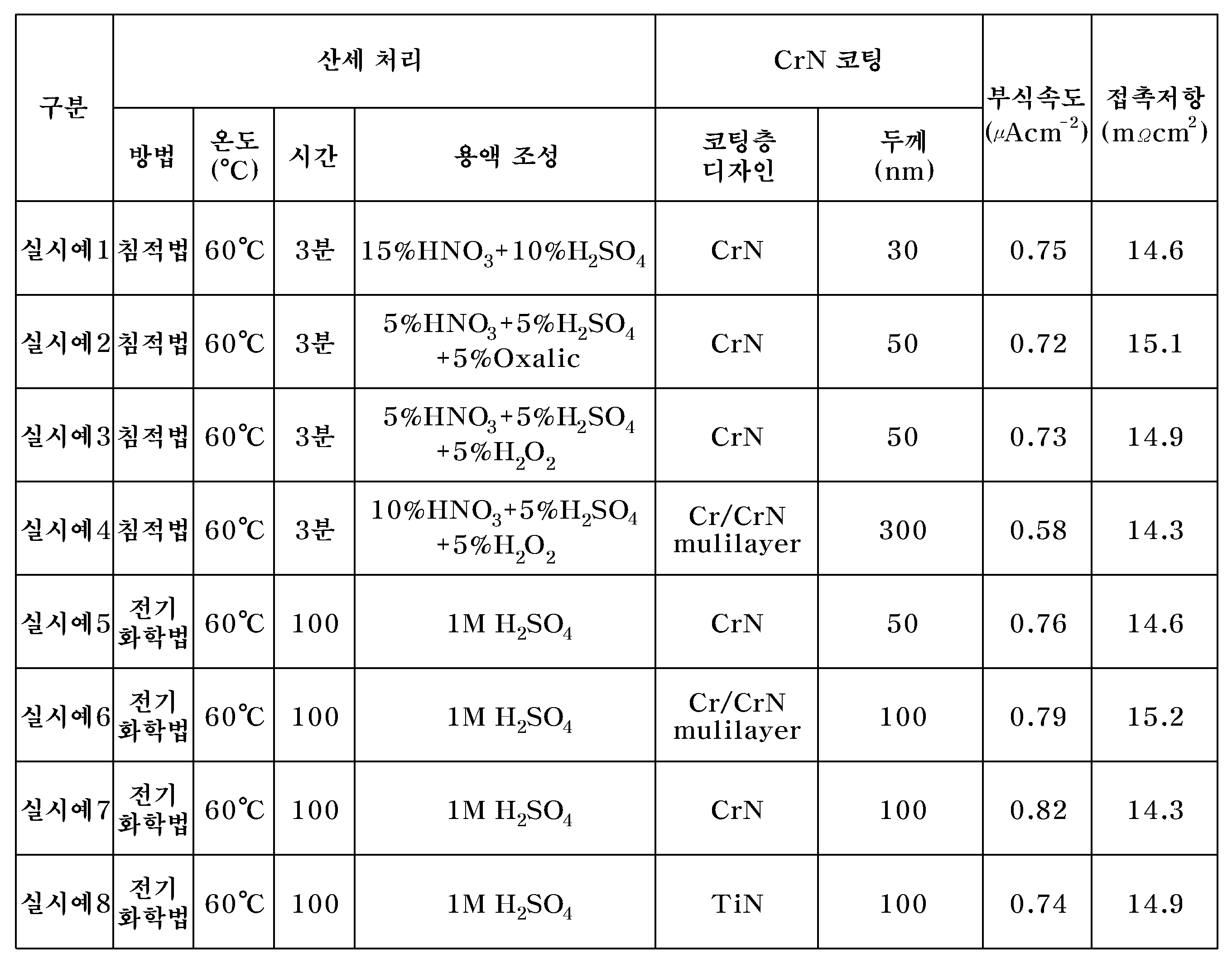


표 1, 표 2와 표3은 스테인리스 강판 모재로서 316L을 사용하여, 침적법과 전기화학법에 의해 각각의 표면개질조건(온도, 시간, 전류밀도, 용액조성), 코팅층 형성조건(코팅층 종류, 디자인, 두께)을 달리하면서 제조되는 본 발명의 실시예 1 ~ 실시예 18 및 비교예들에 따른 스테인리스 분리판에 대하여 부식전류와 접촉저항을 측정한 결과를 나타내는 것이다.Table 1, Table 2 and Table 3 show the surface modification conditions (temperature, time, current density, solution composition) and coating layer formation conditions (coating layer type, design) by using 316L as the base plate of stainless steel sheet by immersion method and electrochemical method. , To show the results of measuring the corrosion current and the contact resistance for the stainless steel separator according to Examples 1 to 18 and Comparative Examples of the present invention manufactured with different thickness).
구체적으로, 실시예 1~실시예 7및 실시예 10의 경우엔 표면개질과 크롬질화물층(CrN 또는 Cr2N) 형성을 동시에 해준 것이고(실시예 4, 실시예 6은 Cr/CrN 다중층(multi-layer)을 형성함), 실시예 8 ~실시예 9와 실시예 11 ~ 실시예18은 티타늄질화물, 탄화물 및 붕소화물(TiN, TiC 또는 TiB2), 지르코늄질화물, 탄화물 또는 붕소화물(ZrN, ZrC 및 ZrB2), 크롬 탄화물 및 붕소화물(Cr3C2, Cr7C3 또는 CrB2) 그리고 텅스텐 탄화물(WC)을 형성해 준것이며, 비교예 1의 경우엔 본 발명에서 제시하는 코팅층(220)의 두께범위를 벗어난 15nm 두께의 크롬질화물(CrN)을 형성한 경우이고, 비교예 2의 경우엔 표면개질만을 해주고 코팅층을 형성해주지 않은 경우이고, 비교예 3의 경우엔 표면개질없이 크롬질화물층(CrN)만을 형성해준 것이다.Specifically, in the case of Examples 1 to 7 and Example 10, the surface modification and chromium nitride layer (CrN or Cr 2 N) was formed at the same time (Example 4, Example 6 were Cr / CrN multilayer ( multi-layers), Examples 8 to 9 and Examples 11 to 18 include titanium nitride, carbides and borides (TiN, TiC or TiB 2 ), zirconium nitrides, carbides or borides (ZrN , ZrC and ZrB 2 ), chromium carbide and boride (Cr 3 C 2 , Cr 7 C 3 or CrB 2 ) and tungsten carbide (WC) were formed, and in the case of Comparative Example 1 the coating layer ( In the case of forming a chromium nitride (CrN) having a thickness of 15 nm outside the thickness range of 220), in the case of Comparative Example 2 only the surface modification and the coating layer is not formed, in the case of Comparative Example 3 chromium nitride without surface modification Only the layer (CrN) was formed.
1. 접촉저항의 측정1. Measurement of contact resistance
도 5는 본 발명에 따른 스테인리스 강판의 접촉저항을 측정하는 접촉저항측정장치를 도시한 도면이다.5 is a view showing a contact resistance measuring device for measuring the contact resistance of the stainless steel sheet according to the present invention.
도 5를 참조하면, 스테인리스 강판(500)의 접촉저항 측정을 위해 셀 체결을 위한 최적화된 상수를 얻기 위해 수정된 데이비드 방법(Davies method)을 스테인리스 스틸(Stainless Steel:SS)과 카본 페이퍼 사이의 접촉저항을 측정하기 위해 사용하였다.Referring to Figure 5, the contact between the stainless steel (SS) and carbon paper modified David method (Davies method) in order to obtain an optimized constant for fastening the cell for measuring the contact resistance of the
접촉저항은 4점법(four-wire current-voltage) 측정 원리를 이용하여 Zahner사의 IM6장비로 측정하였다.Contact resistance was measured with Zahner's IM6 instrument using the four-wire current-voltage measurement principle.
측정방법은 정전류 모드에서 측정 영역 DC 2A 및 AC 0.2A로 하여 10kHz로 부터 10mHz 까지의 범위에서 접촉저항을 측정하였다.In the constant current mode, the contact resistances were measured in the range of 10 kHz to 10 mHz with DC 2A and AC 0.2A.
카본페이퍼는 SGL사의 10BB를 사용하였다.Carbon paper used 10BB of SGL Corporation.
상기 접촉저항측정장치(50)는 카본 페이퍼(520), 금이 도금된 구리플레이트(510)가 시편(500)을 사이에 두고 각각 상하로 마련되고, 상기 구리플레이트(510)는 전류공급장치(530)와 전압측정장치(540)에 연결되어 있다. The contact
상기 시편(500)에 전류를 공급할 수 있는 전류공급장치(530, Zahner사의 IM6)로 DC 2A/AC 0.2A의 전류를 인가하여 전압을 측정하였다. The voltage was measured by applying a current of DC 2A / AC 0.2A to a current supply device 530 (IM6 of Zahner) capable of supplying current to the
그리고, 상기 접촉저항측정장치(50)의 구리플레이트(510) 상하에서 상기 시편(500)과 카본페이퍼(520), 구리 플레이트(510)가 적층구조를 갖도록 압력을 제공할 수 있는 압력기(Instron사 모델 5566, 압축유지시험)를 마련한다. 상기 압력기는 상기 접촉저항 측정 장치(50)에 50 ~ 150N/cm2의 압력을 제공한다.An instron capable of providing pressure so that the
이와 같이 마련된 접촉저항측정장치(50)로 상기 표 1, 표 2에 나타낸 실시예와 비교예의 시편(500) 즉, 스테인리스 강판의 접촉저항을 측정하였다.The contact resistance of the
2. 부식전류의 측정2. Measurement of corrosion current
본 발명의 스테인리스 분리판의 부식전류를 측정하기 측정장비로는 EG&G 273A을 사용하였다. 부식 내구성 실험은 PEFC(Polymer Electrolyte Fuel Cell)의 모사 환경 하에서 이루어 졌다.EG & G 273A was used as a measuring instrument for measuring the corrosion current of the stainless steel separator of the present invention. Corrosion endurance test was carried out under simulated environment of PEFC (Polymer Electrolyte Fuel Cell).
본 발명에 따른 스테인리스 강판의 부식시키는 실험용액으로는 80℃의 0.1N H2SO4 + 2ppm HF 용액을 사용하고, 1시간 동안 O2 bubbling 후 OCP(Open Circuit Potential) - 0.25V ∼ 1V vs SCE 범위에서 측정하였다.As a test solution for corrosion of the stainless steel sheet according to the present invention using 0.1NH 2 SO 4 + 2ppm HF solution at 80 ℃, O 2 bubbling for 1 hour after OCP (Open Circuit Potential)-0.25V ~ 1V vs SCE range Measured at
그리고, PEFC anode 환경에 대해 -0.24V vs SCE, cathode 환경(SCE: Saturated Calomel Electrode)에 대해 0.6V vs SCE에서 물성측정을 하였다.In addition, physical properties were measured at -0.24V vs SCE for PEFC anode environment and 0.6V vs SCE for Saturated Calomel Electrode (SCE).
여기서 상기 물성측정 비교는 연료전지 환경과 유사한 cathode 환경의 0.6V vs SCE의 부식전류 데이터를 통해 비교 평가하였다.Here, the physical property comparison was evaluated through the corrosion current data of 0.6 V vs SCE in the cathode environment similar to the fuel cell environment.
상기 anode 환경은 수소가 막-전극 접합체(Membrane Electrode Assembly, MEA)에서 수소이온과 전자로 분리되는 반응이 일어나는 환경이며, 상기 cathode 환경은 산소가 수소이온 및 전자와 결합하여 물을 생성하는 반응이 일어나는 환경이다.The anode environment is an environment in which hydrogen is separated into hydrogen ions and electrons in a membrane electrode assembly (MEA), and the cathode environment is a reaction in which oxygen combines with hydrogen ions and electrons to generate water. It's an environment that happens.
여기서 상기의 조건과 같이 cathode환경의 전위가 높으며, 더욱 가혹한 부식 조건이기 때문에 cathode 환경을 기준으로 내식성을 시험하는 것이 바람직하다.In this case, since the potential of the cathode environment is high and the harsher corrosion conditions are more severe, it is preferable to test the corrosion resistance based on the cathode environment.
그리고, 고분자 전해질 연료전지 적용을 위해서는 스테인리스 강판의 부식전류밀도가 1μA/cm2 이하의 값으로 나오는 것이 바람직하다.For the application of the polymer electrolyte fuel cell, the corrosion current density of the stainless steel sheet is preferably 1 μA / cm 2 or less.
3. 부식전류 및 접촉저항 측정 결과의 분석3. Analysis of Corrosion Current and Contact Resistance Measurement Results
표 1, 표 2, 표 3을 참조하면, 본 발명의 실시예들과 같이 표면개질-코팅층을 형성해준 경우엔 부식전류가 0.5~1.0㎂/㎠ 사이의 값을 가지고 있음을 알 수 있고, 접촉저항의 경우엔 13~18mΩ·㎠의 값을 나타내고 있음을 알 수 있다.Referring to Table 1, Table 2, and Table 3, when the surface modification-coating layer was formed as in the embodiments of the present invention, it can be seen that the corrosion current has a value between 0.5 to 1.0 mA /
그리고, 비교예 1과 같이 표면개질후 15nm두께의 크롬질화물층을 형성시킨 경우 접촉저항 값은 17.4mΩ·㎠, 부식전류 값은 0.94㎂/㎠, 비교예 2와 같이 표면개질만을 거친 경우엔 접촉저항 값은 17.5mΩ·㎠, 부식전류 값은 0.95㎂/㎠, 비교예 3과 같이 표면개질공정 없이 크롬질화물층만을 형성한 경우엔 접촉저항 값은 35 mΩ·㎠, 부식전류 값은 2.3㎂/㎠의 값을 나타내고 있음을 알 수 있다.In the case of forming a chromium nitride layer having a thickness of 15 nm after surface modification as in Comparative Example 1, the contact resistance value was 17.4 mΩ ·
상기 실시예들과 비교예들의 접촉저항과 부식전류값은 모두 DOE 기준을 만족시키는 값이기는 하나 이는 연료전지를 장시간 동작시키기 이전의 초기 값이기 때문이며, 본 발명에서 주로 관심을 두고 있는 다음에 기재될 연료전지의 장기내구성 평가에서는 상기 실시예들과 비교예들의 값의 차이는 더욱 현저함을 알 수 있다.Although the contact resistance and the corrosion current value of the above embodiments and the comparative examples are all satisfying the DOE standard, this is because the initial value before the fuel cell is operated for a long time, and will be described below. In the long-term durability evaluation of the fuel cell, it can be seen that the difference between the values of the embodiments and the comparative examples is more remarkable.
4. 연료전지 모사환경 내식성 및 접촉저항 평가 및 결과4. Evaluation and results of fuel cell simulation environment corrosion resistance and contact resistance
(1) 모사환경 내식성 및 접촉저항 평가(1) Evaluation of simulated environment corrosion resistance and contact resistance
본 발명의 스테인리스 분리판의 연료전지 환경 모사는 EG&G 273A을 사용하였다. 80℃의 0.1N H2SO4 + 2ppm HF 용액에 시편을 장입하고, 1시간 동안 O2 bubbling 후 시편에 0.6V vs SCE의 정전압을 인가하였다. 일정 시간 동안 정전압 인가 후 시편의 내식성 및 접촉저항을 측정하였다. 위 작업을 반복하면서 장기간 동안 연료전지 모사환경에서의 내식성 및 접촉저항 변화 양상을 평가하였다.The fuel cell environmental simulation of the stainless steel separator of the present invention used EG & G 273A. The specimen was charged in a 0.1NH 2 SO 4 + 2ppm HF solution at 80 ° C., followed by O 2 bubbling for 1 hour, and a constant voltage of 0.6 V vs SCE was applied to the specimen. After applying a constant voltage for a certain time, the corrosion resistance and contact resistance of the specimen were measured. By repeating the above work, the corrosion resistance and contact resistance changes in the fuel cell simulation environment were evaluated for a long time.
(2) 모사환경 내식성 및 접촉저항 평가 결과(2) Evaluation result of simulated environment corrosion resistance and contact resistance
도 6은 상기와 같은 방법으로 측정된 연료전지 모사환경 내식성 평가에 대한 결과를 나타내고 있는 그래프이다.6 is a graph showing the results of the fuel cell simulation environment corrosion resistance measured by the above method.
도 6를 참조하면, 실시예 1과 비교예 2는 초기와 1,000시간 경과후에도 부식전류값이 1㎂/㎠ 이하로 거의 일정하게 유지되고 있음을 알 수 있으나, 비교예 3의 경우엔 장시간 경과후 뿐만 아니라 초기 부식전류값도 1㎂/㎠를 초과하고 있음을 알 수 있는데, 이는 비교예 3에 있어서 CrN층의 박리(exfoliation)때문인 것으로 판단된다.Referring to FIG. 6, it can be seen that in Example 1 and Comparative Example 2, the corrosion current value is maintained almost constant at 1 mA /
도 7은 상기와 같은 방법으로 측정된 연료전지 모사환경에서 실시예1, 실시예4와 실시예8~18 및 비교예1과 비교예2의 시편의 2,000시간 노출후 접촉저항 평가에 대한 결과를 나타내고 있는 그래프이다.FIG. 7 shows the results of the contact resistance evaluation after 2,000 hours exposure of the specimens of Examples 1, 4 and 8 to 18, and Comparative Examples 1 and 2 in the fuel cell simulation environment measured by the above method. This graph is shown.
도 7을 참조하면, 실시예1, 실시예4와 실시예8~18의 경우엔 2,000시간 경과후에도 DOE 기준 이하의 값을 유지하고 있음에 비해, 비교예1, 비교예 2의 경우엔 2,000시간 이후엔 DOE 기준을 초과한 접촉저항 값을 나타내고 있음을 알 수 있다.Referring to FIG. 7, in the case of Examples 1, 4, and 8 to 18, 2,000 hours were obtained in the case of Comparative Example 1 and Comparative Example 2, while the values below the DOE standard were maintained even after 2,000 hours had elapsed. After that, it can be seen that the contact resistance value exceeding the DOE standard is shown.
상기와 같은 결과가 나온 이유는 비교예 1의 경우엔 CrN 층이 박리되거나 혹은 CrN보다 높은 두께로의 부동태 피막 성장 때문이고. 비교예 2의 경우엔 부동태 피막이 계속하여 성장하였기 때문인 것으로 판단되며, 이에 비해 실시예의 경우엔 표면에 형성된 금속화합물층이 그 하부의 부동태 피막의 성장을 억제하는 내부식성 및 전도성 코팅층 역할을 잘 수행하였기 때문인 것으로 판단된다.The reason for the above results was obtained in the case of Comparative Example 1 because the CrN layer was peeled off or the passivation film was grown to a thickness higher than CrN. In Comparative Example 2, the passivation film was continuously grown, whereas in the case of the Example, the metal compound layer formed on the surface performed well as a corrosion resistant and conductive coating layer that suppressed the growth of the passivation film thereunder. It seems to be.
5. 연료전지 장기 내구성 평가 및 결과5. Long-term durability evaluation and results of fuel cell
(1) 장기 내구성 평가 방법(1) long-term durability evaluation method
반응 가스의 공급을 위해 서펜타인 유로를 가지는 분리판을 사용하였으며 분리판 사이에 막-전극 접합체(Gore사의 모델명 5710)와 가스확산층(SGL사의 모델 10BA)을 둔 후 일정압력으로 체결하여 연료전지 셀을 제작하였다.A separator having a serpentine flow path was used to supply the reactant gas, and a membrane-electrode assembly (Gore's model name 5710) and a gas diffusion layer (SGL's model 10BA) were placed between the separator plates and fastened to a constant pressure. The cell was fabricated.
연료전지 성능평가는 단위셀을 이용해 평가하였는데, 연료전지 운전 장치는 NSE Test Station 700W class를 사용하였고 연료전지 성능평가를 위한 전자 부하장치로 KIKUSUI E-Load를 사용하여, 0.01A/cm2 전류 15초-1A/cm2로 전류 15초 사이클을 지속적으로 인가하였다.The fuel cell performance was evaluated using the unit cell. The fuel cell operating device used NSE Test Station 700W class and the electronic load device for fuel cell performance evaluation using KIKUSUI E-Load, 0.01A / cm 2 Current 15 A current 15 second cycle was continuously applied at s- 1 A / cm 2 .
반응가스로는 수소와 공기를 사용하였고, 유량은 전류에 따라 수소 1.5, 공기 2.0의 화학양론비를 일정하게 유지하며 상대습도 100% 가습 후 공급하였다. 가습기와 셀의 온도는 65℃로 일정하게 유지시켜주며 대기압 조건하에서 성능을 평가하였다. 이때, 작동면적(active area)은 25㎠, 작동압력은 1atm 이었다.Hydrogen and air were used as the reaction gas, and the flow rate was supplied after humidifying 100% of relative humidity while maintaining a constant stoichiometric ratio of hydrogen 1.5 and air 2.0 according to the current. Humidifier and cell temperature was kept constant at 65 ℃ and the performance was evaluated under atmospheric pressure conditions. At this time, the active area (active area) was 25
(2) 장기 내구성 평가 결과(2) Long-term durability evaluation result
도 8은 상기 실시예1, 실시예4와 실시예8~18 및 비교예1과 비교예2의 시편을 상기의 장기내구성 평가방법에 따라 2,000시간 경과후의 평가결과를 나타낸 그래프이다.8 is a graph showing the evaluation results after the elapse of 2,000 hours for the specimens of Examples 1, 4 and 8 to 18, and Comparative Examples 1 and 2 according to the long-term durability evaluation method.
도 8을 참조하면, 모두 초기엔 발생전압이 0.62V 이상이였으나, 비교예 1의 경우엔 2,000시간 경과 후 발생전압이 0.58V 정도로 저하되고, 비교예 2의 경우엔 2,000시간 경과 후 발생전압이 0.57V로 저하된다.Referring to FIG. 8, in all cases, the generated voltage was initially 0.62V or more, but in the case of Comparative Example 1, the generated voltage was reduced to about 0.58V after 2,000 hours. In Comparative Example 2, the generated voltage was 0.57V after the 2,000 hours. Falls to V.
이에 비하여 본 발명의 실시예1, 실시예4와 실시예8~18에 의해 제조되는 스테인리스 분리판을 사용한 연료전지의 경우엔 내구성이 매우 우수하여 2,000시간 경과하더라도 초기에 비해 0.02V 미만의 미소량의 발생전압 저하가 나타내고 있음을 알 수 있다.In contrast, fuel cells using stainless steel separators manufactured according to Examples 1, 4, and 8 to 18 of the present invention have excellent durability and have a small amount of less than 0.02V compared to the initial stage even after 2,000 hours. It can be seen that a decrease in the generated voltage is indicated.
도 1은 본 발명에 따른 연료전지용 스테인리스 분리판의 제조방법을 설명하기 위한 공정흐름도이다.1 is a process flow diagram illustrating a method of manufacturing a stainless steel separator plate for fuel cells according to the present invention.
도 2 내지 도 4는 상기 도 1의 각 공정단계에 있어서의 공정사시도를 나타낸 것이다.2 to 4 show a process perspective view in each process step of FIG.
도 5는 본 발명에 따른 스테인리스 강판의 접촉저항을 측정하는 접촉저항측정장치를 도시한 도면이다.5 is a view showing a contact resistance measuring device for measuring the contact resistance of the stainless steel sheet according to the present invention.
도 6은 실시예1과 비교예2및 비교예3의 시편에 대한 연료전지 모사환경 내식성 평가에 대한 결과를 나타내고 있는 그래프이다.6 is a graph showing the results of the fuel cell simulation environment corrosion resistance evaluation for the specimens of Example 1, Comparative Example 2 and Comparative Example 3.
도 7은 실시예 1, 실시예4, 실시예 8~18과 비교예 1, 2의 시편에 대한 연료전지 모사환경 접촉저항 평가에 대한 결과를 나타내고 있는 그래프이다.7 is a graph showing the results of fuel cell simulated environmental contact resistance evaluation for the specimens of Examples 1, 4, 8 and 18 and Comparative Examples 1 and 2. FIG.
도 8는 실시예 1, 실시예4, 실시예 8~18과 비교예 1의 시편을 상기의 장기내구성 평가방법에 따라 평가한 결과를 나타낸 그래프이다.8 is a graph showing the results of evaluation of the specimens of Examples 1, 4, 8 and 18 and Comparative Example 1 according to the long-term durability evaluation method described above.
Claims (17)
Priority Applications (10)
| Application Number | Priority Date | Filing Date | Title |
|---|---|---|---|
| KR1020080037916A KR100885041B1 (en) | 2008-04-23 | 2008-04-23 | Stainless separator for fuel cell having coating layer selected from mnx, m/mnx, mcy, mbz and method for the same |
| EP09158149.6A EP2112250B1 (en) | 2008-04-23 | 2009-04-17 | Stainless separator for fuel cell and method of manufacturing the same |
| US12/426,150 US9070907B2 (en) | 2008-04-23 | 2009-04-17 | Stainless separator for fuel cell and method of manufacturing the same |
| JP2009103823A JP5222214B2 (en) | 2008-04-23 | 2009-04-22 | Stainless steel separator for fuel cell and method for producing the same |
| CN2009101360198A CN101567455B (en) | 2008-04-23 | 2009-04-23 | Stainless steel separator for fuel cells and a method of manufacturing same |
| JP2012105239A JP5518934B2 (en) | 2008-04-23 | 2012-05-02 | Stainless steel separator for fuel cell and method for producing the same |
| US14/471,960 US9337495B2 (en) | 2008-04-23 | 2014-08-28 | Stainless separator for fuel cell and method of manufacturing the same |
| US14/700,676 US9425450B2 (en) | 2008-04-23 | 2015-04-30 | Stainless separator for fuel cell and method of manufacturing the same |
| US14/700,707 US9331343B2 (en) | 2008-04-23 | 2015-04-30 | Stainless separator for fuel cell and method of manufacturing the same |
| US14/700,732 US9337496B2 (en) | 2008-04-23 | 2015-04-30 | Stainless separator for fuel cell and method of manufacturing the same |
Applications Claiming Priority (1)
| Application Number | Priority Date | Filing Date | Title |
|---|---|---|---|
| KR1020080037916A KR100885041B1 (en) | 2008-04-23 | 2008-04-23 | Stainless separator for fuel cell having coating layer selected from mnx, m/mnx, mcy, mbz and method for the same |
Publications (1)
| Publication Number | Publication Date |
|---|---|
| KR100885041B1 true KR100885041B1 (en) | 2009-02-20 |
Family
ID=40681968
Family Applications (1)
| Application Number | Title | Priority Date | Filing Date |
|---|---|---|---|
| KR1020080037916A KR100885041B1 (en) | 2008-04-23 | 2008-04-23 | Stainless separator for fuel cell having coating layer selected from mnx, m/mnx, mcy, mbz and method for the same |
Country Status (2)
| Country | Link |
|---|---|
| KR (1) | KR100885041B1 (en) |
| CN (1) | CN101567455B (en) |
Cited By (2)
| Publication number | Priority date | Publication date | Assignee | Title |
|---|---|---|---|---|
| CN102471916A (en) * | 2009-07-23 | 2012-05-23 | 杰富意钢铁株式会社 | Stainless steel for fuel cell having excellent corrosion resistance and method for producing same |
| KR101261188B1 (en) * | 2012-03-07 | 2013-05-09 | 군산대학교산학협력단 | Method and system for manufacturing fuel cell bipolar plate |
Families Citing this family (10)
| Publication number | Priority date | Publication date | Assignee | Title |
|---|---|---|---|---|
| US8834734B2 (en) * | 2011-06-06 | 2014-09-16 | GM Global Technology Operations LLC | Surface alloying of stainless steel |
| CN104611679B (en) * | 2014-11-28 | 2017-04-05 | 武汉工程大学 | Nanocrystalline ZrC/Zr composite coatings of one proton exchanging film fuel battery titanium alloy bipolar plates and preparation method thereof |
| CN104617316B (en) * | 2014-11-28 | 2017-03-29 | 武汉工程大学 | Nanocrystalline ZrBN/Zr composite coatings of one metal double-plate for proton exchange film fuel cell and preparation method thereof |
| CN104746123A (en) * | 2015-04-11 | 2015-07-01 | 常州大学 | Technical method for electrochemical modification on surface of 316L stainless steel |
| CN107195920B (en) * | 2017-06-15 | 2019-10-11 | 常州翊迈新材料科技有限公司 | Fuel cell has both conductive and anti-corrosion function coating material |
| CN107171003B (en) * | 2017-06-15 | 2020-05-05 | 常州翊迈新材料科技有限公司 | Conductive super-corrosion-resistant functional coating material |
| CN109136851B (en) * | 2018-09-01 | 2020-09-04 | 华迪钢业集团有限公司 | Corrosion-resistant post-treatment process for stainless steel pipe |
| CN110699647A (en) * | 2019-10-31 | 2020-01-17 | 宇石能源(南通)有限公司 | Method for modifying stainless steel bipolar plate of fuel cell |
| CN111029606B (en) * | 2019-12-20 | 2022-02-25 | 佛山国防科技工业技术成果产业化应用推广中心 | Metal boride-based composite coating for fuel cell bipolar plate and preparation method thereof |
| CN115020734A (en) * | 2022-05-19 | 2022-09-06 | 中国空间技术研究院 | Fuel cell metal bipolar plate composite coating and preparation method thereof |
Citations (4)
| Publication number | Priority date | Publication date | Assignee | Title |
|---|---|---|---|---|
| JP2003123783A (en) | 2001-10-17 | 2003-04-25 | Nisshin Steel Co Ltd | Stainless steel separator for low temperature fuel cell |
| JP2006318652A (en) | 2005-05-10 | 2006-11-24 | Nisshin Steel Co Ltd | Solid oxide type fuel cell separator material |
| KR20070096257A (en) * | 2006-03-23 | 2007-10-02 | 김수경 | Method of preparing seperator of fuel cell and separator of fuel cell |
| KR100791274B1 (en) * | 2007-06-20 | 2008-01-04 | 현대하이스코 주식회사 | Stainless steel separator for fuel cell and method for manufacturing the same |
Family Cites Families (2)
| Publication number | Priority date | Publication date | Assignee | Title |
|---|---|---|---|---|
| DE10306649A1 (en) * | 2003-02-18 | 2004-09-02 | Forschungszentrum Jülich GmbH | Protective layer for substrates exposed to high temperatures, and method for producing the same |
| JP2008078115A (en) * | 2006-08-24 | 2008-04-03 | Nissan Motor Co Ltd | Transition metal nitride, fuel cell separator, manufacturing method of transition metal nitride, manufacturing method of fuel cell separator, fuel cell stack and fuel cell vehicle |
-
2008
- 2008-04-23 KR KR1020080037916A patent/KR100885041B1/en active IP Right Grant
-
2009
- 2009-04-23 CN CN2009101360198A patent/CN101567455B/en active Active
Patent Citations (4)
| Publication number | Priority date | Publication date | Assignee | Title |
|---|---|---|---|---|
| JP2003123783A (en) | 2001-10-17 | 2003-04-25 | Nisshin Steel Co Ltd | Stainless steel separator for low temperature fuel cell |
| JP2006318652A (en) | 2005-05-10 | 2006-11-24 | Nisshin Steel Co Ltd | Solid oxide type fuel cell separator material |
| KR20070096257A (en) * | 2006-03-23 | 2007-10-02 | 김수경 | Method of preparing seperator of fuel cell and separator of fuel cell |
| KR100791274B1 (en) * | 2007-06-20 | 2008-01-04 | 현대하이스코 주식회사 | Stainless steel separator for fuel cell and method for manufacturing the same |
Cited By (3)
| Publication number | Priority date | Publication date | Assignee | Title |
|---|---|---|---|---|
| CN102471916A (en) * | 2009-07-23 | 2012-05-23 | 杰富意钢铁株式会社 | Stainless steel for fuel cell having excellent corrosion resistance and method for producing same |
| CN102471916B (en) * | 2009-07-23 | 2013-04-24 | 杰富意钢铁株式会社 | Stainless steel for fuel cell having excellent corrosion resistance and method for producing same |
| KR101261188B1 (en) * | 2012-03-07 | 2013-05-09 | 군산대학교산학협력단 | Method and system for manufacturing fuel cell bipolar plate |
Also Published As
| Publication number | Publication date |
|---|---|
| CN101567455A (en) | 2009-10-28 |
| CN101567455B (en) | 2012-05-09 |
Similar Documents
| Publication | Publication Date | Title |
|---|---|---|
| KR100885041B1 (en) | Stainless separator for fuel cell having coating layer selected from mnx, m/mnx, mcy, mbz and method for the same | |
| JP5222214B2 (en) | Stainless steel separator for fuel cell and method for producing the same | |
| KR100791274B1 (en) | Stainless steel separator for fuel cell and method for manufacturing the same | |
| KR101165542B1 (en) | Metal separator for fuel cell having coating film and method for the same | |
| JP5634604B2 (en) | Separator for fuel cell and method for producing the same | |
| CN101542794A (en) | Fuel cell separator and method for producing the same | |
| KR100909374B1 (en) | Method for manufacturing the seperator of fuel cell comprising pickling and heat treatment process and seperator by the same | |
| KR100844023B1 (en) | Stainless separator for fuel cell having metal coating surface and method for the same | |
| KR100796526B1 (en) | Stainless separator for fuel cell having discontinuous crn surface layer and method for the same | |
| KR100777125B1 (en) | Metallic bipolar plate coated by chromium nitride for fuel cell and its manufacturing method | |
| KR100867819B1 (en) | Surface layer of metal bipolar plate for fuel cell and method for creating the same |
Legal Events
| Date | Code | Title | Description |
|---|---|---|---|
| A201 | Request for examination | ||
| A302 | Request for accelerated examination | ||
| E902 | Notification of reason for refusal | ||
| E701 | Decision to grant or registration of patent right | ||
| GRNT | Written decision to grant | ||
| FPAY | Annual fee payment |
Payment date: 20130201 Year of fee payment: 5 |
|
| FPAY | Annual fee payment |
Payment date: 20140203 Year of fee payment: 6 |
|
| FPAY | Annual fee payment |
Payment date: 20150202 Year of fee payment: 7 |
|
| FPAY | Annual fee payment |
Payment date: 20160127 Year of fee payment: 8 |
|
| FPAY | Annual fee payment |
Payment date: 20170207 Year of fee payment: 9 |
|
| FPAY | Annual fee payment |
Payment date: 20180206 Year of fee payment: 10 |
|
| FPAY | Annual fee payment |
Payment date: 20190123 Year of fee payment: 11 |
|
| FPAY | Annual fee payment |
Payment date: 20200120 Year of fee payment: 12 |