KR100841541B1 - Method and apparatus for reducing interference within a communication system - Google Patents
Method and apparatus for reducing interference within a communication system Download PDFInfo
- Publication number
- KR100841541B1 KR100841541B1 KR1020057016062A KR20057016062A KR100841541B1 KR 100841541 B1 KR100841541 B1 KR 100841541B1 KR 1020057016062 A KR1020057016062 A KR 1020057016062A KR 20057016062 A KR20057016062 A KR 20057016062A KR 100841541 B1 KR100841541 B1 KR 100841541B1
- Authority
- KR
- South Korea
- Prior art keywords
- signal
- interference
- calculating
- correlation matrix
- spatial correlation
- Prior art date
Links
Images


Classifications
-
- H—ELECTRICITY
- H04—ELECTRIC COMMUNICATION TECHNIQUE
- H04B—TRANSMISSION
- H04B1/00—Details of transmission systems, not covered by a single one of groups H04B3/00 - H04B13/00; Details of transmission systems not characterised by the medium used for transmission
- H04B1/06—Receivers
- H04B1/10—Means associated with receiver for limiting or suppressing noise or interference
-
- H—ELECTRICITY
- H04—ELECTRIC COMMUNICATION TECHNIQUE
- H04B—TRANSMISSION
- H04B7/00—Radio transmission systems, i.e. using radiation field
- H04B7/02—Diversity systems; Multi-antenna system, i.e. transmission or reception using multiple antennas
- H04B7/04—Diversity systems; Multi-antenna system, i.e. transmission or reception using multiple antennas using two or more spaced independent antennas
- H04B7/08—Diversity systems; Multi-antenna system, i.e. transmission or reception using multiple antennas using two or more spaced independent antennas at the receiving station
- H04B7/0837—Diversity systems; Multi-antenna system, i.e. transmission or reception using multiple antennas using two or more spaced independent antennas at the receiving station using pre-detection combining
- H04B7/0842—Weighted combining
- H04B7/0848—Joint weighting
- H04B7/0854—Joint weighting using error minimizing algorithms, e.g. minimum mean squared error [MMSE], "cross-correlation" or matrix inversion
-
- H—ELECTRICITY
- H04—ELECTRIC COMMUNICATION TECHNIQUE
- H04B—TRANSMISSION
- H04B15/00—Suppression or limitation of noise or interference
-
- H—ELECTRICITY
- H04—ELECTRIC COMMUNICATION TECHNIQUE
- H04B—TRANSMISSION
- H04B15/00—Suppression or limitation of noise or interference
- H04B15/02—Reducing interference from electric apparatus by means located at or near the interfering apparatus
-
- H—ELECTRICITY
- H04—ELECTRIC COMMUNICATION TECHNIQUE
- H04L—TRANSMISSION OF DIGITAL INFORMATION, e.g. TELEGRAPHIC COMMUNICATION
- H04L27/00—Modulated-carrier systems
- H04L27/26—Systems using multi-frequency codes
- H04L27/2601—Multicarrier modulation systems
- H04L27/2602—Signal structure
- H04L27/2605—Symbol extensions, e.g. Zero Tail, Unique Word [UW]
- H04L27/2607—Cyclic extensions
-
- H—ELECTRICITY
- H04—ELECTRIC COMMUNICATION TECHNIQUE
- H04L—TRANSMISSION OF DIGITAL INFORMATION, e.g. TELEGRAPHIC COMMUNICATION
- H04L27/00—Modulated-carrier systems
- H04L27/26—Systems using multi-frequency codes
- H04L27/2601—Multicarrier modulation systems
- H04L27/2647—Arrangements specific to the receiver only
Abstract
통신 시스템 내의 간섭을 감소시키는 방법이 본원에 제공되어 있다. 이 방법은 목적 신호 s(n) 및 공동-채널 간섭 신호 i(n)를 포함하는 신호 y(n)을 수신하는 단계 (여기서, s(n) 및 i(n)은 시간-동기화되지 않음); y(n)를 주파수-영역 신호 Y(k)로 변환시키는 단계(105); s(n) 및 i(n)에 기초하고, 추가로 s(n)과 i(n) 사이에 존재하는 타임 오프셋 T에 기초하여 가중 벡터 W(k)를 계산하는 단계(109); 및 목적 신호 s(n)를 등화시키고, 공동-채널 간섭 i(n)을 감소시키기 위해 W(k)를 Y(k)에 인가하는 단계(11)를 포함한다.

통신 시스템, 채널 간섭 신호, 주파수-영역 신호, 타임 오프셋, 목적 신호
Provided herein are methods of reducing interference in a communication system. The method comprises receiving a signal y (n) comprising a destination signal s (n) and a co-channel interference signal i (n), where s (n) and i (n) are not time-synchronized). ; converting y (n) to a frequency-domain signal Y (k) (105); calculating 109 a weighting vector W (k) based on s (n) and i (n) and further based on a time offset T existing between s (n) and i (n); And applying 11 to equalize the desired signal s (n) and apply W (k) to Y (k) to reduce co-channel interference i (n).
Communication system, channel interference signal, frequency-domain signal, time offset, destination signal
Description
본 발명은 일반적으로 간섭 감소에 관한 것이며, 상세하게는 통신 시스템 내의 간섭 감소 방법 및 그 장치에 관한 것이다.The present invention generally relates to interference reduction, and more particularly, to a method and apparatus for interference reduction in a communication system.
간섭은 종종 통신 시스템들의 성능을 저해한다. 통신 시스템의 사용자가 종종 직면하게 되는 간섭의 한가지 유형은 다른 사용자들의 전송들에 의해 발생된 간섭이다. 이는 전형적으로 동일한 주파수 대역 내에서 전송하는 많은 사용자들에 의해 유발되고, 공동-채널 간섭(co-channel interference)이라 칭한다. 공동-채널 간섭을 감소시키기 위해, 많은 통신 시스템들은 주파수 재사용 패턴을 사용하고, 여기서 인접하는 셀들의 송신기들은 상이한 주파수들 상으로 전송한다. 그러나, 스펙트럼의 가격을 감안할 때, 미래의 통신 시스템들은 현저히 증가된 공동-채널 간섭 레벨들을 초래하게 될 공격적인 주파수 재사용 패턴들을 특징으로 할 것이다.Interference often hinders the performance of communication systems. One type of interference that users of communication systems often face is interference caused by transmissions of other users. This is typically caused by many users transmitting within the same frequency band and is called co-channel interference. In order to reduce co-channel interference, many communication systems use a frequency reuse pattern, where transmitters of neighboring cells transmit on different frequencies. However, given the price of the spectrum, future communication systems will be characterized by aggressive frequency reuse patterns that will result in significantly increased co-channel interference levels.
상기 상황에도 불구하고, 점점 더 많은 시스템 오퍼레이터들이 정보를 전송하기 위해 인가받지 않은 주파수 대역들의 이점을 취하고 있다. 인가받지 않은 주파수 대역 내의 송신기들의 수는 제한되지 않기 때문에, 크게 증가된 공동-채널 간섭 가능성이 존재한다. 추가로, 인가받지 않은 대역 내의 오퍼레이터들은 공통 소스에 대해 동기화되지 않아야 하기 때문에, 전형적인 공동-채널 간섭은 비동기화되고, 여기서 간섭 신호는 제 시간 내에 목적 신호와 정렬되지 않는다.Notwithstanding the above situation, more and more system operators are taking advantage of unlicensed frequency bands for transmitting information. Since the number of transmitters in the unlicensed frequency band is not limited, there is a greatly increased possibility of co-channel interference. In addition, typical co-channel interference is asynchronous because operators in the unlicensed band should not be synchronized to a common source, where the interference signal is not aligned with the destination signal in time.
공동-채널 간섭은 통신 시스템의 효율을 크게 감소시킬 수 있고, 공동-채널 간섭은 동기적일 수도 비동기적일 수도 있기 때문에, 통신 시스템 내의 동기 및 비동기 공동-채널 간섭을 감소시키는 방법 및 그 장치가 필요하다.Since co-channel interference can greatly reduce the efficiency of a communication system, and co-channel interference may be synchronous or asynchronous, there is a need for a method and apparatus for reducing synchronous and asynchronous co-channel interference in a communication system. .
도 1은 본 발명의 바람직한 실시예에 따른 수신기의 블록도.1 is a block diagram of a receiver in accordance with a preferred embodiment of the present invention.
도 2는 본 발명의 바람직한 실시예에 따른 전형적인 프레임 구조를 예시하는 도면.2 illustrates an exemplary frame structure in accordance with a preferred embodiment of the present invention.
도 3은 본 발명의 바람직한 실시예에 따른 도 1의 가중 계산기의 블록도.3 is a block diagram of the weighting calculator of FIG. 1 in accordance with a preferred embodiment of the present invention.
도 4는 본 발명의 바람직한 실시예에 따른 도 1의 수신기의 오퍼레이션을 나타낸 흐름도.4 is a flow diagram illustrating the operation of the receiver of FIG. 1 in accordance with a preferred embodiment of the present invention.
고도의 주파수-선택 전파 채널에서, 채널 주파수 응답에서 변화들을 정확히 트래킹하는 능력은 임의의 간섭 감소 알고리즘의 적절한 오퍼레이션에 대해 중요하다. 본 발명의 방법 및 장치는 간섭을 감소하기 위해 복수개의 수신 안테나들의 출력들을 조합하는 개선된 기술을 제공한다. 본 발명의 방법 및 장치는 통신 수신 디바이스, 기지국 또는 가입자 유닛 내에 포함될 수 있다. 본 발명에서, "디바이스(device)"라는 용어는 기지국, 가입자 유닛 또는 기타 통신 수신기 또는 송신기 등의 임의의 유형의 통신 디바이스를 의미할 수 있다.In highly frequency-selected propagation channels, the ability to accurately track changes in channel frequency response is important for proper operation of any interference reduction algorithm. The method and apparatus of the present invention provide an improved technique for combining the outputs of a plurality of receive antennas to reduce interference. The method and apparatus of the present invention may be included in a communication receiving device, base station or subscriber unit. In the present invention, the term "device" may refer to any type of communication device, such as a base station, subscriber unit or other communication receiver or transmitter.
본 발명의 바람직한 실시예에 따라, 통신 시스템 내의 간섭을 감소시키는 방법 및 장치가 본원에 제공된다. 이 방법은 목적 신호 s(n) 및 공동-채널 간섭 신호 i(n)를 포함하는 신호 y(n)을 수신하는 단계 (여기서, s(n) 및 i(n)은 시간-동기화되지 않음); y(n)를 주파수-영역 신호 Y(k)로 변환시키는 단계; s(n) 및 i(n)에 기초하고, 추가로 s(n)과 i(n) 사이에 존재하는 타임 오프셋 T에 기초하여 가중 벡터 W(k)를 계산하는 단계; 및 목적 신호 s(n)를 등화시키고, 공동-채널 간섭 i(n)을 감소시키기 위해 W(k)를 Y(k)에 인가하는 단계를 포함한다. 비동기화 시스템에 대해, W(k)는 수신기에 유지된 시간 기준으로부터 목적 신호 및 간섭기 모두의 타이밍 오프셋에 기초하여 계산된다.In accordance with a preferred embodiment of the present invention, a method and apparatus for reducing interference in a communication system are provided herein. The method comprises receiving a signal y (n) comprising a destination signal s (n) and a co-channel interference signal i (n), where s (n) and i (n) are not time-synchronized). ; converting y (n) to a frequency-domain signal Y (k); calculating a weight vector W (k) based on s (n) and i (n) and further based on a time offset T existing between s (n) and i (n); And equalizing the desired signal s (n) and applying W (k) to Y (k) to reduce co-channel interference i (n). For an asynchronous system, W (k) is calculated based on the timing offset of both the desired signal and the interferer from the time reference held at the receiver.
이하, 도면으로 돌아가서, 동일한 번호들은 동일한 성분들을 지정하고, 도 1은 본 발명의 바람직한 실시예에 따른 수신기(100)의 블록도이다. 수신기(100)는 OFDM 통신 시스템 프로토콜을 이용하지만, 본 발명의 대안의 실시예들에서, 다른 시스템 프로토콜들이 마찬가지로 이용될 수 있다. 그러한 다른 시스템 프로토콜들은 주기적 프리픽스들을 갖는 주파수-영역 등화 단일-캐리어 시스템들(주기적 프리픽스 단일 캐리어라 칭함), 주기적 프리픽스들을 갖는 코드 분할 다중 액세스 시스템들(주기적 프리픽스 CDMA라 칭함), 다중-캐리어 CDMA 시스템들, 및 스프레드-OFDM 시스템들을 포함하지만, 이들로만 제한되지 않는다. 결과적으로, 본 발명은 OFEM 시스템들, CP-단일 캐리어 시스템들, CP-CDMA 시스템들 및 임의의 기타 유사한 또는 혼성 시스템들에 적용될 수 있고, 효과적이다. 도시된 바와 같이, 수신기(100)는 적어도 하나의 안테나(101), 주기적 프리픽스 제거기(105), 고속 푸리에 변환기(FFT)(105), 및 채널 추정기(107)를 포함한다. 당업계에 알려져 있는 바와 같이, 상기 소자들의 정확한 수는 수신기에 의해 동시에 수신되는 채널들의 양에 따라 변화할 것이다. 간단히 하기 위해, 단지 2개의 수신된 신호들이 도시되고: 즉, s(n)은 목적하는 송신기(즉, 수신기가 추정하려 시도하는 데이터를 갖는 송신기)로부터 수신된 신호이고, i(n)은 간섭하는 송신기로부터 수신된 신호이다. 목적하는 송신기는 목적하는 신호 또는 목적하는 사용자라 칭하기도 한다. s(n) 및 i(n) 모두는 이들의 각각의 채널들에 의해 변조된 후 각각의 송신기들로부터 수신된 신호이다. 본 발명의 바람직한 실시예에서, s(n) 및 i(n)은 공동 시간 소스에 대해 동기화될 수 있거나, 또는 동기화될 수 없음을 이해해야 한다.Turning now to the figures, like numerals designate like components, and FIG. 1 is a block diagram of a
동시에 수신되고 있는 신호들의 수와 무관하게, 수신기(100)는 가중 계산기(109) 및 조합기(111)를 포함한다. 본 발명의 바람직한 실시예에서, 수신기(100)는 토마스(Thomas) 등의 미합중국 특허 제 6,141,393 호, METHOD AND DEVICE FOR CHANNEL ESTIMATION, EQUALIZATION, AND INTERFERENCE SUPPRESSION에 개시된 수신기와 유사하고, 이 특허는 참고 문헌으로서 본원에 인용된다. '393호 특허에 개시된 바와 같이, 효과적인 간섭 감소를 허용하도록 통신 시스템의 주파수 응답을 정확히 트래킹하는 방법 및 디바이스를 갖는 것이 유리하다. 이러한 과업을 수행하기 위해, 가중 계산기(109)는 목적 신호 s(n)를 등화시키고, 공동-채널 간섭 i(n)을 감소시키기 위해 수신된 신호 y(n)에 인가되는 적절한 채널 가중들을 계산한다. 그러나, '393호 특허와 달리, 동기 및 비동기 간섭기들 모두는 본 발명의 수신기에 의해 감소된다. 또한, '393호 특허와 달리, 목적 신호의 동기 및 비동기 부분 모두는 목적 신호를 등화시킬 때 본 발명의 수신기(100)에 의해 설명된다. 이것이 어떻게 수행되는지에 대한 더 상세한 설명은 도 1 및 도 2 모두를 참조하여 아래 기재된다.Regardless of the number of signals being received at the same time, the
도 2는 본 발명의 바람직한 실시예에 따라 전형적인 프레임 구조(200)를 예시한다. 바람직한 실시예에서, 복수개의 송신 디바이스들은 복수개의 안테나(101)를 갖는 수신기(100)에 정보를 동시에 전송한다. 본 발명의 바람직한 실시예에서, 모든 송신 디바이스들은 3개의 성분들: 즉, 주기적 프리픽스(201), 데이터 블록(203) 및 트레이닝(파일럿) 시퀀스(205)를 포함하는 버스트들 내의 정보를 전송한다. 그러나, 다른 실시예들에서, 주기적 프리픽스(201)는 제거될 수 있다. 프레임 구조(200)는 길이 Lcp의 주기적 프리픽스(201) + 데이터 기호들의 블록(203) 또는 길이 N의 각각의 파일럿 기호들의 블록(205)으로 구성된 기호 블록들로 분할될 수 있다. 도면에서, -Lcp≤n≤N-1에 대해, N+Lcp 기호들의 블록 x(n,b)인 제1 기호 블록은 블록 b라 칭할 것이고, 데이터 기호들만을 포함한다. -Lcp≤n≤N-1에 대해, N+Lcp 기호들의 다른 블록 x(n,b)인 제 2 기호 블록(블록 b+1)은 파일럿 기호들만을 포함한다. 바람직한 실시예에서, 주기적 프리픽스(201)에 포함된 정보는 기호 블록의 최종 Lcpn(여기서 Lcp ≥0) 시간-영역 기호들의 수신을 포함한다. 등식 형태에서, 이러한 반복은 -Lcp≤n≤-1에 대해 x(n,b)=x(n+N,b)로 표현된다.2 illustrates a
본 발명의 다른 실시예들에서, 주기적 프리픽스는 트레이닝 기호들 또는 널 기호들 등의 알려져 있는 기호들을 포함할 수 있다. 더욱이, 다른 실시예들은 기호 블록의 처음과 끝 사이에 주기적 프리픽스 (또는 널 프리픽스(null prefix), 또는 주기적 중복도의 다른 형태들) 분할을 가질 수 있다. 목적하는 송신기 및 간섭기는 상이한 주기적 프리픽스 길이들을 가질 수 있고, 따라서 Ld cp 및 Ll cp는 목적 신호의 주기적 프리픽스 길이 및 간섭기의 주기적 프리픽스 길이 각각의 길이를 지정하기 위해 사용된다. Ld cp 및 Ll cp 모두는 0 이상일 수 있고, 여기서 0의 값은 어떠한 주기적 프리픽스들도 사용되지 않음을 의미한다. 트레이닝 간격(205)에 전송된 정보는 송신 디바이스들 및 수신기(100) 모두에 의해 알려져 있는 콘텐트 및 기간의 파일럿 신호 시퀀스들을 포함한다. 프레임 구조(200)는 데이터 기호들만을 포함하는 것으로 도시된 블록(203)보다 상이한 기호 블록(207) 내에 있는 파일럿 기호들의 블록(205)을 포함하는 것에 주의하자. 대안의 실시예들에서, 블록(203)에 포함되는 것으로 도시된 데이터 기호들은 파일럿 기호들 및 데이터 기호들 모두를 포함하는 기호 블록을 포함하도록 205에 포함된 것으로 도시된 파일럿 기호들과 혼합될 수 있는 한편, 파일럿 및 데이터 기호들은 시간 또는 주파수 영역들에 체류한다. 목적 송신기의 기호들은 xa(n,b)로 지정되고, 수신기가 회복하고자 시도하는 것이다. 간섭기의 기호들은 xi(n,b)로 지정된다.In other embodiments of the invention, the periodic prefix may include known symbols, such as training symbols or null symbols. Moreover, other embodiments may have a periodic prefix (or null prefix, or other forms of periodic redundancy) split between the beginning and the end of the symbol block. The desired transmitter and interferer can have different periodic prefix lengths, so L d cp and L l cp are used to specify the length of each of the periodic prefix length of the desired signal and the periodic prefix length of the interferer. Both L d cp and L l cp may be greater than or equal to 0, where a value of 0 means that no periodic prefixes are used. The information transmitted in
오퍼레이션 중에, Mx1 신호 y(n) (여기서, M은 수신 안테나들의 수이고, n은 시간 샘플 지수를 지시한다)은 적어도 하나의 안테나(101)를 도입한다. 등식 형태에서, y(n)은 다음과 같이 주어진다:During operation, Mx1 signal y (n), where M is the number of receive antennas and n indicates the time sample index, introduces at least one
y(n) = s(n) + i(n) + e(n) (1)y (n) = s (n) + i (n) + e (n) (1)
여기서, e(n)은 파워 σ2 n를 갖는 수신기 잡음의 Mx1 벡터이다. e(n)은 다음과 같이 주어지는 i(n)에 포함되지 않는 임의의 간섭 신호들을 포함할 수도 있다. s(n) 및 e(n)은 다음과 같이 주어진다:Where e (n) is the Mx1 vector of receiver noise with power σ 2 n . e (n) may include any interfering signals not included in i (n) given as follows. s (n) and e (n) are given by:

여기서, Ld는 사용자의 시간-영역 채널의 길이이고, Li는 간섭기의 시간-영역 채널의 길이이고, hd t(0≤ℓ≤Ld-1)는 목적 사용자에 대해 래그 ℓ에서 Mx1 시간-영역 채널 벡터이고, hi t(0≤ℓ≤Li-1)는 간섭기에 대해 래그 ℓ에서 Mx1 시간-영 역 채널 벡터이고, Td는 목적 사용자에 대한 타이밍 오프셋이고, Ti는 간섭기에 대한 타이밍 오프셋이고, (n)N은 n 모듈러 N을 의미하고, ![]()
![]()
신호 y(n)은 목적하는 Mx1 신호 s(n), Mx1인 모든 간섭 신호들 i(n), 및 잡음 e(n)을 포함한다. y(n)은 복조되고, 기호 시간 b에서 목적 신호 s(n)의 주기적 프리픽스 부분에 대응하는 y(n)의 부분은 주기적 프리픽스 제거기(103)(즉, 수신기는 오프셋 Td를 고려하지 않고 목적 신호로 동기화됨)에 의해 제거되고, 0≤n≤N-1에 대해 Mx1 신호 r(n,b)를 초래한다. 등식 형태에서, r(n,b)는 다음과 같이 주어진다:Signal y (n) comprises the desired Mx1 signal s (n), all interfering signals i (n) that are Mx1, and noise e (n). y (n) is demodulated, and the portion of y (n) that corresponds to the periodic prefix portion of the destination signal s (n) at symbol time b is the periodic prefix canceller 103 (i.e., the receiver does not consider the offset T d) . Synchronized to the desired signal), resulting in Mx1 signal r (n, b) for 0 < In the form of equations, r (n, b) is given by:

주기적 프리픽스 제거 후, 신호는 FFT 오퍼레이션(105)을 통해 주파수-영역 신호, Y(k,b)로 변환되고, 여기서 k는 주파수 (또는 서브캐리어) 지수를 지시한다. 등식 형태에서, Y(k,b)는 다음과 같이 주어진다:After cyclic prefix removal, the signal is converted to a frequency-domain signal, Y (k, b) via

파일럿 간격들에 대응하는 시간 지수들 b에 대한 주파수-영역 신호, Y(k,b)는 목적 신호 + 모든 간섭기들에 대한 채널 추정이 발생하는 채널 추정기들(107)을 도입한다. 보다 상세하게는 (단순성에 대한 단일 간섭기만이 존재한다고 가정하면), 목적 신호 및 간섭의 각각의 채널 길이들에 대한 Mx1 시간-영역 채널들 hd t 및 hi t 각각 목적 신호 및 간섭의 각각의 채널 길이 Ld 및 Li 각각은 잡음 파워 σ2 n의 추정치 및 목적 신호 및 간섭에 대한 타이밍 오프셋, Td 및 Ti 각각에 따라 추정된다. 목적 신호 및 간섭기 모두에 대한 시간-영역 채널들은 가중들 W(k)을 조합하는 계산을 단순화시키기 위해 시간 내에 변화하지 않는 것으로 가정된다. 다른 실시예들에서, 채널 추정기는 채널들에서 변화들에 응답하여 시간 변화들 및 조합 가중 변경을 트래킹한다.The frequency-domain signal, Y (k, b), for the time indices b corresponding to the pilot intervals introduces
수신된 시간-영역 신호, y(n)와 마찬가지로, 주파수-영역 신호 Y(k,b)는 다음과 같이 목적 신호, 간섭 및 잡음의 합으로서 표현될 수도 있다:Like the received time-domain signal y (n), the frequency-domain signal Y (k, b) may be expressed as the sum of the target signal, interference and noise as follows:
![]()
![]()
여기서:here:

'393호 특허에 개시된 바와 같이, 가중 계산기(109)는 데이터(203)에 인가하기 위해 적절한 가중을 계산함으로써 목적 사용자의 주파수-영역 신호 S(k,b)는 등화되고, 주파수-영역 간섭 신호 I(k,b)는 감소되거나 또는 주파수-영역 잡음 E(k,b)를 현저히 증진시킴 없이 제거된다. 보다 상세하게는, 목적 사용자의 트레이닝 기간(205) 동안, 채널 추정기(107)의 출력들은 아래 기재된 바와 같이 Mx1 가중 W(k)를 계산하기 위해 사용된다. 선행 기술과 달리, 본 발명의 바람직한 실시예에서, W(k)는 비동기 및 동기 간섭 모두가 제거되도록 계산된다. 이러한 간섭 제거는 비동기 간섭기의 일부 및 동기 간섭기의 일부를 고려함으로써 주파수 영역 내의 간섭기의 적절한 모델링에 의해 달성된다. 간섭은 W(k)의 계산에 적절한 모델링을 사용함으로써 최적으로 제거된다. 또한, 선행 기술과 달리, 본 발명의 바람직한 실시예에서, W(k)는 목적 신호의 비동기 부분 및 동기 부분 모두가 고려되도록 계산된다. 목적 신호의 비동기 부분을 고려함으로써, 선행 기술보다 양호한 조합 가중 W(k)가 계산된다.As disclosed in the '393 patent, the
슬롯(200)의 데이터 부분 동안, W(k)가 Y(k,b)에 인가됨으로써, 간섭이 감소되고, 목적 사용자의 주파수-영역 신호들의 추정치가 얻어진다. 등식 형태에서, 이러한 조합 오퍼레이션은 다음과 같이 주어진다:During the data portion of
![]()
![]()
여기서, H는 콘쥬게이트 전치 행렬 연산자이고, ![]()
![]()
![]()
![]()
상기한 바와 같이, 선행 기술의 간섭 감소와는 달리, 본 발명의 바람직한 실시예에서, W(k)는 비동기 및 동기 간섭 모두가 제거되도록 결정된다. 특히, 대부분의 현존하는 통신 시스템들은 다른 셀들로부터의 간섭을 감소하려 시도하지 않고, 대신에 단순히 그것을 잡음으로 취급한다. 간섭을 감소함으로써, 시스템 용량의 현저한 개선들이 달성될 수 있다.As noted above, in contrast to the interference reduction of the prior art, in a preferred embodiment of the present invention, W (k) is determined such that both asynchronous and synchronous interference are eliminated. In particular, most existing communication systems do not attempt to reduce interference from other cells, but instead simply treat it as noise. By reducing the interference, significant improvements in system capacity can be achieved.
주기적-프리픽스 통신 시스템에서, 비동기 간섭기는 주기적 프리픽스가 목적 신호의 주기적 프리픽스와 시간 내에 정렬되지 않는 신호로서 정의된다(다시 말하자면, Ti≠0). 이는 주파수 영역에서, 비동기 간섭기가 데이터 기호에 의해 승산된 서브-캐리어에 대해 간섭기의 채널로서 주어진 서브-캐리어에 대해 모델링될 수 없음을 의미한다. 따라서, 주파수-영역 비동기 간섭기 신호의 정확한 모델이 필요하다. 추가로, Td≠0 또는 Ld cp > Ld인 경우, 목적 신호의 주파수-영역 신호의 정확한 모델이 필요하다. 이어지는 분석을 위해, 0 ≤Td ≤N-Ld cp 및 0 ≤Ti ≤N-Li cp인 것으로 가정된다. 이어지는 분석을 간단히 하기 위해, b=0으로 가정된다. 목적 사용자 및 간섭기에 대해 수신된 Mx1 시간-영역 신호들 (M은 수신 안테나들의 수이다)은 (상기 가정 및 0≤n≤N-1에 대해서만) 다음과 같이 주어진다:In a periodic-prefix communication system, an asynchronous interferer is defined as a signal whose periodic prefix is not aligned in time with the periodic prefix of the target signal (ie, T i ≠ 0). This means that in the frequency domain, an asynchronous interferer cannot be modeled for a given sub-carrier as the channel of the interferer for the sub-carrier multiplied by the data symbol. Thus, there is a need for an accurate model of the frequency-domain asynchronous interferer signal. In addition, when T d ≠ 0 or L d cp > L d , an accurate model of the frequency-domain signal of the desired signal is required. For the subsequent analysis, it is assumed that 0 ≦ T d ≦ NL d cp and 0 ≦ T i ≦ NL i cp . To simplify the analysis that follows, b = 0 is assumed. The received Mx1 time-domain signals (M is the number of receive antennas) for the destination user and interferer are given as follows (only for the hypothesis above and 0≤n≤N-1):

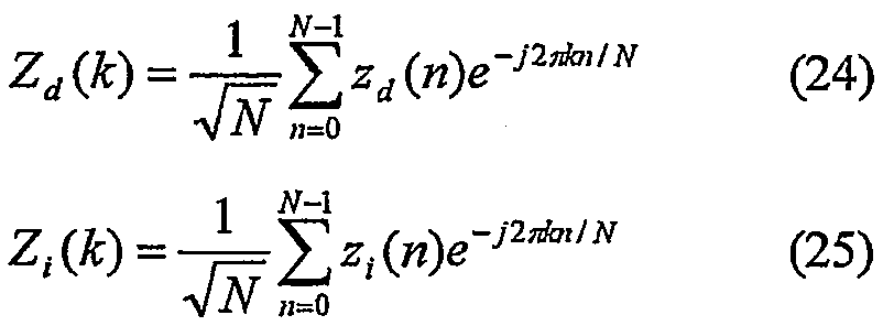
여기서 '~'는 이들이 0≤n≤N-1에 대해서만 정의된다는 점에서 s(n) 및 i(n)과 상이함을 나타내기 위해 사용된다. zd(n) 및 zi(n)은 분석을 간단히 하기 위해 사용되고 다음과 같이 주어진다:Here '~' is used to indicate that they are different from s (n) and i (n) in that they are defined only for 0≤n≤N-1. z d (n) and z i (n) are used to simplify the analysis and are given as follows:

목적 신호 및 간섭기 모두는 -Ld cp≤n≤-1에 대해 zd(n)= zd(n+N) 및 -Li cp≤n≤-1에 대해 zi(n)= zi(n+N)이 되도록 삽입된 주기적 프리픽스들을 갖는 것에 주의하자. 분석은 목적 신호 및 간섭 신호 모두가 주기적 프리픽스들을 갖는다고 가정하지만, 분석은 또한 아래에 기술되는 바와 같이 어떠한 주기적 프리픽스도 갖지 않는 신호들에 대해 유지된다. 수신된 신호들은 다음과 같이 나타낼 수 있다:Both the target signal and the interferer have z d (n) = z d (n + N) for -L d cp ≤ n ≤ -1 and z i (n) = z i for -L i cp ≤ n ≤ -1 Note that there are periodic prefixes inserted such that (n + N). The analysis assumes that both the object signal and the interfering signal have periodic prefixes, but the analysis is also maintained for signals that do not have any periodic prefixes as described below. The received signals can be represented as follows:

(16) 및 (17)에서 제 1 항은 신호들의 동기 부분을 나타내고, (16) 및 (17)에서 제 2 항은 비동기 부분에 대응한다. Td(Ti)가 충분히 큰 경우, 목적 신호(간섭기)의 동기 부분은 0일 것임에 주의하자. 어떠한 주기적 프리픽스도 갖지 않는 목적 신호들(간섭기들)에 대해, 비동기 부분들만이 존재하고, Td(Ti)는 Ld cp+1(Li cp+1)로 설정된다.In (16) and (17), the first term represents the synchronous part of the signals, and in (16) and (17) the second term corresponds to the asynchronous part. Note that if T d (T i ) is large enough, the synchronization portion of the target signal (interference) will be zero. For destination signals (interferences) that do not have any periodic prefix, only asynchronous portions exist, and T d (T i ) is set to L d cp +1 (L i cp +1).
![]()
![]()

(16)을 (18)로, (17)을 (19)로 치환시키고, 단순화시킴으로써, ![]()
![]()
![]()
![]()

여기서:here:
Hd s(k) 및 Hi s(k)는 목적 사용자의 채널 및 간섭기의 채널 각각의 동기 부분이고, 여기서:H d s (k) and H i s (k) are the synchronization portions of each of the channel of the target user and the channel of the interferer, where:

hd t는 목적 사용자의 시간-영역 채널이고;h d t is the time-domain channel of the destination user;
hi t는 간섭기의 시간-영역 채널이고;h i t is the time-domain channel of the interferer;
Zd(k) 및 Zi(k)는 목적 사용자의 시간-영역 기호들 및 간섭기의 시간-영역 기호들 각각의 FFT이고, 여기서Z d (k) and Z i (k) are the FFT of each of the time-domain symbols of the destination user and the time-domain symbols of the interferer, where
Hd s(k)(Hi s(k))는 목적 신호(간섭기)가 완전히 비동기인 경우 0일 수 있음에 주의하자. ![]()
![]()
가중들 W(k)를 조합한 최소 평균 제곱 에러(MMSE)는 서브캐리어 k에 대한 목적 사용자의 공간 상관 매트릭스 Rd(k), 서브캐리어 k에 대한 간섭기의 공간 상관 매트릭스 Ri(k), 및 잡음의 공간 상관 매트릭스 RE(k)(전형적으로 RE(k) = σ2 nIM 여기서, IM은 MxM 항등 매트릭스(identity matrix)이다)를 필요로 한다. 조합 가중 W(k)는 다음 식에 대한 해(solution)로 밝혀진다:The minimum mean squared error (MMSE) combining the weights W (k) is the spatial correlation matrix R d (k) of the destination user for subcarrier k, the spatial correlation matrix R i (k) of the interferer for subcarrier k, And a spatial correlation matrix R E (k) of noise (typically R E (k) = σ 2 n I M where I M is an MxM identity matrix). The combinatorial weight W (k) is found to be the solution to the following equation:
![]()
![]()
여기서, Ex()는 예상 연산자이다. W(k)에 대한 해는 다음으로 나타낼 수 있다:Where Ex () is an expected operator. The solution to W (k) can be expressed as:
![]()
![]()
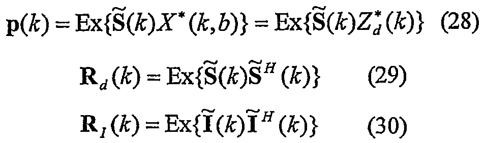
여기서, Mx1 교차 상관 벡터 p(k) 및 목적 사용자 및 간섭기에 대한 공간 상관 매트릭스들은 다음과 같다:Here, the Mx1 cross correlation vector p (k) and spatial correlation matrices for the destination user and the interferer are as follows:
조합 가중 W(k)는 식(27) 내에서 간섭기가 존재함을 가정함에 주의하자. 본 발명은 또한 어떠한 간섭기도 존재하지 않을 때 목적 신호의 비동기 부분 및 동기 부분 모두에 대해 고려함으로써 선행 기술의 등화 능력들을 개선할 수 있다. 선행 기술과 달리, 본 발명의 바람직한 실시예에서, W(k)는 목적 사용자의 주파수-영역 신호의 비동기 및 동기 성분들 모두가 어떠한 간섭 신호도 존재하지 않을 때 수신된 신호를 등화할 때를 고려되도록 계산된다. 어떠한 간섭도 없는 경우, 조합 가중들은 다음과 같이 주어진다:Note that the combinatorial weight W (k) assumes that an interferer is present in equation (27). The present invention can also improve the equalization capabilities of the prior art by considering both the asynchronous and synchronous portions of the desired signal when no interferer is present. Unlike the prior art, in a preferred embodiment of the present invention, W (k) considers when both the asynchronous and synchronous components of the frequency-domain signal of the target user equalize the received signal when no interference signal is present. Is calculated to be. In the absence of any interference, the combination weights are given as follows:
![]()
![]()
p(k), Rd(k) 및 RI(k)를 결정하기 위해, ![]()
![]()
![]()
![]()

여기서:here:

p(k)는 다음과 같이 Ss(k) 및 Sa(k)에 관하여 표현될 수 있다:p (k) can be expressed in terms of S s (k) and S a (k) as follows:
![]()
![]()
Rd(k)는 이하 다음과 같이 Ss(k) 및 Sa(k)에 관하여 표현될 수 있다:R d (k) can be expressed in terms of S s (k) and S a (k) as follows:
![]()
![]()
Ri(k)는 이하 다음과 같이 Is(k) 및 Ia(k)에 관하여 표현될 수 있다:R i (k) can be expressed in terms of I s (k) and I a (k) as follows:
![]()
![]()
(38), (39) 및 (40)에서 항들을 평가하기 위해, 목적 사용자 및 간섭기에 대한 시간-영역 기호들 사이의 상관, Rd zz(n,m) 및 Ri zz(n,m) 각각, 목적 사용자 및 간섭기에 대한 주파수-영역 기호들 사이의 상관, Rd ZZ(k) 및 Ri ZZ(k) 각각, 및 목적 사용자 및 간섭기에 대한 주파수-영역과 시간-영역 기호들 사이의 교차-상관, Rd Zz(k,m) 및 Ri Zz(k,m) 각각이 정의되어야 한다. 이들 상관들은 사용된 변조 유형 (예, OFDM 또는 단일 캐리어)에 의존할 것이다. 이들 상관 함수들은 다음과 같이 정의된다:Correlation between time-domain symbols for the destination user and the interferer, R d zz (n, m) and R i zz (n, m), to evaluate the terms at (38), (39) and (40). Respectively, the correlation between frequency-domain symbols for the destination user and the interferer, R d ZZ (k) and R i ZZ (k), respectively, and between the frequency-domain and time-domain symbols for the destination user and the interferer, respectively. Cross-correlation, R d Zz (k, m) and R i Zz (k, m) respectively must be defined. These correlations will depend on the type of modulation used (eg OFDM or single carrier). These correlation functions are defined as follows:

주파수-영역 및 시간-영역 기호들 사이의 교차-상관은 다음과 같이 시간-영역 기호들 사이의 상관에 관하여 표현될 수 있다:The cross-correlation between frequency-domain and time-domain symbols can be expressed in terms of correlation between time-domain symbols as follows:

상관 함수들을 사용함으로써, (38), (39) 및 (40)에서 상이한 항들은 다음과 같이 나타낼 수 있다:By using correlation functions, the different terms at (38), (39) and (40) can be represented as follows:

목적 사용자의 상관 함수들에 대한 전형적인 가정들은 다음과 같다:Typical assumptions about the objective user's correlation functions are:

여기서:here:

(59)에서 상관은 주기적 프리픽스와 블록 내의 최종 기호들 사이의 상관에 대해 설명하지 못하고, 그 이유는 이러한 상관이 목적 사용자의 비동기 부분에 대해서만 사용되기 때문이다.The correlation at (59) does not account for the correlation between the cyclic prefix and the final symbols in the block, since this correlation is used only for the asynchronous portion of the destination user.
간섭기의 상관 함수들에 대한 전형적인 가정들은 다음과 같다:Typical assumptions for the correlation functions of the interferer are:

여기서:here:

(62)에서 상관은 주기적 프리픽스와 블록 내의 최종 기호들 사이의 상관에 대해 설명하지 못하고, 그 이유는 이러한 상관이 간섭기의 비동기 부분에 대해서만 사용되기 때문이다.The correlation at 62 does not account for the correlation between the cyclic prefix and the final symbols in the block, because this correlation is used only for the asynchronous portion of the interferer.
(59) 및 (60)에서의 가정들을 사용함으로써, p(k)는 다음과 같이 나타낼 수 있다:By using the assumptions at (59) and (60), p (k) can be expressed as:

(59) 및 (60)에서의 가정들을 사용함으로써, Rd(k)는 다음과 같이 나타낼 수 있다:By using the assumptions at (59) and (60), R d (k) can be represented as:

여기서, Mx1 Hd a(k), MxM Rd c(k) 및 MxM Rd x(k)는 다음과 같이 주어진다:Where Mx1 H d a (k), MxM R d c (k) and MxM R d x (k) are given as:

항 Rd x(k)는 (20)의 동기 부분과 비동기 부분 간의 교차-상관을 설명하기 위해 필요하다.The term R d x (k) is needed to describe the cross-correlation between the synchronous and asynchronous portions of (20).
(62) 및 (63)에서의 가정들을 사용함으로써, RI(k)는 다음과 같이 나타낼 수 있다:By using the assumptions at (62) and (63), R I (k) can be represented as:
![]()
![]()
여기서, Mx1 Hi a(k), MxM Ri c(k) 및 MxM Ri x(k)는 다음과 같이 주어진다:Where Mx1 H i a (k), MxM R i c (k) and MxM R i x (k) are given as:

항 Ri x(k)는 (21)의 동기 부분과 비동기 부분 사이의 교차-상관을 설명하기 위해 필요하다. 선행 기술과 달리, Rd(k) 및 Ri(k) 모두는 등식에 대한 동기 성분 및 비동기 성분 모두를 포함하는 것에 주의해야 한다. 추가로, Rd(k)는 비동기 및 동기 목적 주파수 영역 신호 사이의 교차-상관을 포함하고, RI(k)는 비동기 및 동기 주파수 영역 간섭 신호 사이의 교차 상관을 포함한다.The term R i x (k) is necessary to describe the cross-correlation between the synchronous and asynchronous portions of (21). Unlike the prior art, it should be noted that both R d (k) and R i (k) include both synchronous and asynchronous components for the equation. In addition, R d (k) includes cross-correlation between asynchronous and synchronous destination frequency domain signals, and R I (k) includes cross correlation between asynchronous and synchronous frequency domain interference signals.
도 3은 본 발명의 바람직한 실시예에 따른 도 1의 가중 계산기(109)의 블록도이다. 도시된 바와 같이, 가중 계산기(109)는 상관 매트릭스들 Rd(k) 및 RI(k)를 계산하기 위해 사용된 논리 회로(301), 교차 상관 매트릭스 p(k)를 계산하기 위해 사용된 논리 회로(303), 및 잡음 상관 매트릭스 RE(k)를 계산하기 위해 사용된 논리 회로(305) 및 W(k)를 계산하기 위해 사용된 논리 회로(307)를 포함한다.3 is a block diagram of the
본 발명의 바람직한 실시예에 따른 가중 계산기(109)의 오퍼레이션은 도 4에 나타낸다. 논리 흐름은 단계(401)에서 시작하고, 여기서 논리 회로(301)는 서브캐리어에 대한 목적 사용자의 공간 상관 매트릭스 k(Rd(k)) 및 서브캐리어에 대한 간섭기의 공간 상관 매트릭스 k(Ri(k))를 계산한다. 상기 고찰한 바와 같이, Rd(k)는 상기 식(66)에 정의되어 있고, 목적 사용자의 동기 주파수 채널 Hd s(k), 목적 사용자의 비동기 주파수-영역 채널 Hd a(k), 목적 사용자의 정정 매트릭스 Rd c(k) 및 목적 사용자의 교차 상관 매트릭스 Rd s(k)에 기초한다. 선행 기술과 달리, 바람직한 실시예에서 목적 사용자의 비동기 부분은 MMSE 조합 가중들 W(k)을 계산할 때 비동기 부분과 함께 고려된다. 추가로, Ri(k)는 상기 식(70)에 정의되어 있고, 간섭기의 동기 주파수-영역 채널 Hi s(k), 간섭기의 비동기 주파수-영역 채널 Hi a(k), 간섭기의 정정 매트릭스 Ri c(k) 및 간섭기의 교차 상관 매트릭스 Ri s(k)에 기초한다. 선행 기술과 달리, 바람직한 실시예에서 간섭 신호의 비동기 부분은 MMSE 조합 가중들 W(k)을 계산할 때 비동기 부분과 함께 고려된다.The operation of the
계속하여, 단계 (403)에서 p(k)가 계산된다. p(k)는 식(65)에서 정의되고, 목적 사용자에 대한 타이밍 오프셋 Td, 목적 사용자의 주파수-영역 채널의 비동기 부분 Hd s(k), 및 모든 래그들 ℓ에서 목적 사용자의 시간-영역 채널 hd t에 기초한다. 선행 기술과 달리, 바람직한 실시예에서 MMSE 조합 가중들 W(k)을 계산할 때 목적 신호(존재하는 경우)의 비동기 부분을 고려한다.Subsequently, p (k) is calculated in
계속하여, 단계(405)에서, 잡음의 공간 상관 매트릭스 RE(k)(전형적으로, RE(k)= σ2 nIM, 여기서, IM은 MxM 항등 매트릭스이다)가 계산된다. 상기 고찰한 바와 같이, 바람직한 실시예에서, RE(k)는 잡음 파워 σ2 n에만 기초한다.Subsequently, in
마지막으로, 단계(409)에서, W(k)가 계산된다. 상기 고찰한 바와 같이, W(k) = (Rd(k) + RI(k) + RE(k))-1p(k). W(k)는 동기 및 비동기 공동-채널 간섭 모두에 기초하기 때문에, 공동-채널 간섭의 감소는 크게 감소되고, 통신 시스템의 효율 및 신뢰도는 증가된다.Finally, at step 409, W (k) is calculated. As discussed above, W (k) = (R d (k) + R I (k) + R E (k)) -1 p (k). Since W (k) is based on both synchronous and asynchronous co-channel interference, the reduction of co-channel interference is greatly reduced, and the efficiency and reliability of the communication system are increased.
본 발명을 특정 실시예를 참조하여 특별히 도시하고 기재하였지만, 당업계의 숙련자라면 본 발명의 정신 및 범위에서 벗어나지 않는 형태 및 세부 사항의 다양한 변화들이 그 속에서 이루어질 수 있음을 이해할 것이다. 예를 들면, 상기 설명은 다중 간섭 디바이스들에서, 전송 소스가 식(3)에 따라 모델링되는 경우를 상세히 설명한다. 상기 기술들을 이용함으로써 전송 디바이스 상의 추가의 전송 안테나가 식(3)에 따라 모델링되는 경우에, 간섭하는 송신기가 1개 이상의 안테나를 갖는 경우에 적용될 수도 있다. 상기 설명은 또한 다수의 목적하는 송신 디바이스들 이 존재하고, 이는 공간 분할 다중 액세스 또는 SDMA, 시나리오인 경우에 적용될 수도 있다. 상기 기술들은 또한 목적 사용자가 공간 멀티플렉싱 방식으로 다중 전송 안테나들에 의해 전송하고, 이는 다중 입력 다중 출력 또는 MIMO 시나리오인 경우에 적용될 수도 있다. 따라서, 본 발명의 대안의 실시예들은 MIMO, SDMA 또는 MIMO 및 SDMA 모두의 조합에 적용될 수 있다. MIMO 또는 SDMA 경우들에서, 다중 조합 가중들이 형성될 수 있고, 그중 하나는 각각의 입사된 바람직한 신호이다. 입사된 바람직한 신호들 중의 하나에 대한 조합 가중들을 계산할 때, 모든 다른 입사 신호들은 그들 신호들 중 어느 것이 다수의 바람직한 디바이스들(SDMA 경우)로부터 기원하는 신호들 또는 공동-위치 전송 안테나(MIMO 경우)로부터 전송된 다른 신호들인지 무관하게, 간섭으로 취급될 수 있다. 그러한 변화들은 다음 특허 청구의 범위에서 나오도록 의도된다.While the invention has been particularly shown and described with reference to specific embodiments, those skilled in the art will recognize that various changes in form and details may be made therein without departing from the spirit and scope of the invention. For example, the above description details the case where the transmission source is modeled according to equation (3) in multiple interfering devices. By using the above techniques, where an additional transmit antenna on the transmitting device is modeled according to equation (3), it may be applied where the interfering transmitter has one or more antennas. The above description also exists for a number of desired transmitting devices, which may be applied in the case of space division multiple access or SDMA, scenario. The techniques also allow the destination user to transmit by multiple transmit antennas in a spatial multiplexing manner, which may be applied in the case of multiple input multiple output or MIMO scenarios. Thus, alternative embodiments of the present invention can be applied to MIMO, SDMA or a combination of both MIMO and SDMA. In MIMO or SDMA cases, multiple combination weights may be formed, one of which is each incident preferred signal. When calculating the combinatorial weights for one of the incident signals desired, all other incident signals are either signals originating from a number of preferred devices (SDMA case) or co-location transmit antenna (MIMO case). It can be treated as interference, regardless of whether it is other signals transmitted from it. Such changes are intended to come within the scope of the following claims.
Claims (15)
Applications Claiming Priority (2)
| Application Number | Priority Date | Filing Date | Title |
|---|---|---|---|
| US10/375,438 | 2003-02-27 | ||
| US10/375,438 US7221722B2 (en) | 2003-02-27 | 2003-02-27 | Method and apparatus for reducing interference within a communication system |
Publications (2)
| Publication Number | Publication Date |
|---|---|
| KR20060002783A KR20060002783A (en) | 2006-01-09 |
| KR100841541B1 true KR100841541B1 (en) | 2008-06-26 |
Family
ID=32926266
Family Applications (1)
| Application Number | Title | Priority Date | Filing Date |
|---|---|---|---|
| KR1020057016062A KR100841541B1 (en) | 2003-02-27 | 2004-02-12 | Method and apparatus for reducing interference within a communication system |
Country Status (5)
| Country | Link |
|---|---|
| US (1) | US7221722B2 (en) |
| EP (1) | EP1602177A2 (en) |
| KR (1) | KR100841541B1 (en) |
| CN (1) | CN1748371A (en) |
| WO (1) | WO2004077709A2 (en) |
Families Citing this family (55)
| Publication number | Priority date | Publication date | Assignee | Title |
|---|---|---|---|---|
| US8611311B2 (en) * | 2001-06-06 | 2013-12-17 | Qualcomm Incorporated | Method and apparatus for canceling pilot interference in a wireless communication system |
| CN1643867B (en) * | 2003-06-22 | 2010-06-23 | 株式会社Ntt都科摩 | Device and method for estimating channels |
| US20050059366A1 (en) * | 2003-09-16 | 2005-03-17 | Atheros Communications, Inc. | Spur mitigation techniques |
| US6996197B2 (en) * | 2003-09-17 | 2006-02-07 | Motorola, Inc. | Method and apparatus for reducing interference within a communication system |
| US7006840B2 (en) * | 2003-09-30 | 2006-02-28 | Interdigital Technology Corporation | Efficient frame tracking in mobile receivers |
| US7366089B2 (en) * | 2003-10-08 | 2008-04-29 | Atheros Communications, Inc. | Apparatus and method of multiple antenna receiver combining of high data rate wideband packetized wireless communication signals |
| US8040986B2 (en) * | 2003-11-26 | 2011-10-18 | Texas Instruments Incorporated | Frequency-domain subchannel transmit antenna selection and power pouring for multi-antenna transmission |
| US8027417B2 (en) * | 2003-12-19 | 2011-09-27 | Nortel Networks Limited | Interference-weighted communication signal processing systems and methods |
| JP2005269392A (en) * | 2004-03-19 | 2005-09-29 | Nec Electronics Corp | Receiving device, receiving method, and communication system and device |
| US7983142B2 (en) * | 2004-03-30 | 2011-07-19 | Intel Corporation | Apparatus, systems, and methods for the reception and synchronization of asynchronous signals |
| CN100359959C (en) * | 2004-06-01 | 2008-01-02 | 华为技术有限公司 | Method for implementing channel estimation in OFDMA system |
| CA2582957C (en) * | 2004-10-11 | 2013-09-03 | 2Wire Inc. | Periodic impulse noise mitigation in a dsl system |
| US7953163B2 (en) * | 2004-11-30 | 2011-05-31 | Broadcom Corporation | Block linear equalization in a multicarrier communication system |
| US7508863B2 (en) * | 2004-12-13 | 2009-03-24 | Alcatel-Lucent Usa Inc. | Method of processing multi-path signals |
| US8099123B2 (en) | 2004-12-23 | 2012-01-17 | Qualcomm Incorporated | Adaptation of transmit subchannel gains in a system with interference cancellation |
| US8406695B2 (en) * | 2004-12-23 | 2013-03-26 | Qualcomm Incorporated | Joint interference cancellation of pilot, overhead and traffic channels |
| US8442441B2 (en) | 2004-12-23 | 2013-05-14 | Qualcomm Incorporated | Traffic interference cancellation |
| US8422955B2 (en) * | 2004-12-23 | 2013-04-16 | Qualcomm Incorporated | Channel estimation for interference cancellation |
| EP2254264A3 (en) * | 2005-01-05 | 2013-11-13 | ATC Technologies, LLC | Adaptive beam forming with multi-user detection and interference reduction in satellite communication systems and methods |
| US7852950B2 (en) * | 2005-02-25 | 2010-12-14 | Broadcom Corporation | Methods and apparatuses for canceling correlated noise in a multi-carrier communication system |
| US9374257B2 (en) * | 2005-03-18 | 2016-06-21 | Broadcom Corporation | Methods and apparatuses of measuring impulse noise parameters in multi-carrier communication systems |
| CN100446453C (en) * | 2005-07-19 | 2008-12-24 | 电子科技大学 | Communication method for distributed multi-input muti-output orthogonal frequency division multiplexing communication system |
| US8855704B2 (en) * | 2005-08-26 | 2014-10-07 | Qualcomm Incorporated | Fast cell selection in TD-CDMA (UMTS TDD) |
| US8472877B2 (en) * | 2005-10-24 | 2013-06-25 | Qualcomm Incorporated | Iterative interference cancellation system and method |
| US8068464B2 (en) * | 2005-10-27 | 2011-11-29 | Qualcomm Incorporated | Varying scrambling/OVSF codes within a TD-CDMA slot to overcome jamming effect by a dominant interferer |
| US8130727B2 (en) * | 2005-10-27 | 2012-03-06 | Qualcomm Incorporated | Quasi-orthogonal allocation of codes in TD-CDMA systems |
| US8385388B2 (en) | 2005-12-06 | 2013-02-26 | Qualcomm Incorporated | Method and system for signal reconstruction from spatially and temporally correlated received samples |
| US7813439B2 (en) * | 2006-02-06 | 2010-10-12 | Broadcom Corporation | Various methods and apparatuses for impulse noise detection |
| US7894774B2 (en) * | 2007-08-02 | 2011-02-22 | Wireless Technology Solutions Llc | Communication unit and method for interference mitigation |
| US9094986B2 (en) | 2008-02-07 | 2015-07-28 | Qualcomm, Incorporated | Synchronous and asynchronous interference management |
| US8483620B2 (en) | 2008-02-07 | 2013-07-09 | Qualcomm Incorporated | Asynchronous interference management |
| US7848221B2 (en) * | 2008-07-14 | 2010-12-07 | Motorola Mobility, Inc. | Method and system for detecting adjacent channel interference from OFDM/OFDMA based broadband wireless access |
| US8605837B2 (en) * | 2008-10-10 | 2013-12-10 | Broadcom Corporation | Adaptive frequency-domain reference noise canceller for multicarrier communications systems |
| WO2011054369A1 (en) * | 2009-11-03 | 2011-05-12 | Telefonaktiebolaget Lm Ericsson (Publ) | Multi-standard communication |
| CN102148787A (en) * | 2010-02-10 | 2011-08-10 | 思亚诺移动芯片有限公司 | Method, circuit and system for reducing or eliminating receiving signal noises |
| US10051643B2 (en) | 2011-08-17 | 2018-08-14 | Skyline Partners Technology Llc | Radio with interference measurement during a blanking interval |
| US9474080B2 (en) | 2011-08-17 | 2016-10-18 | CBF Networks, Inc. | Full duplex backhaul radio with interference measurement during a blanking interval |
| US10708918B2 (en) | 2011-08-17 | 2020-07-07 | Skyline Partners Technology Llc | Electronic alignment using signature emissions for backhaul radios |
| US8928542B2 (en) | 2011-08-17 | 2015-01-06 | CBF Networks, Inc. | Backhaul radio with an aperture-fed antenna assembly |
| US10716111B2 (en) | 2011-08-17 | 2020-07-14 | Skyline Partners Technology Llc | Backhaul radio with adaptive beamforming and sample alignment |
| US8238318B1 (en) | 2011-08-17 | 2012-08-07 | CBF Networks, Inc. | Intelligent backhaul radio |
| US10764891B2 (en) | 2011-08-17 | 2020-09-01 | Skyline Partners Technology Llc | Backhaul radio with advanced error recovery |
| US8761100B2 (en) | 2011-10-11 | 2014-06-24 | CBF Networks, Inc. | Intelligent backhaul system |
| US8422540B1 (en) | 2012-06-21 | 2013-04-16 | CBF Networks, Inc. | Intelligent backhaul radio with zero division duplexing |
| US8502733B1 (en) | 2012-02-10 | 2013-08-06 | CBF Networks, Inc. | Transmit co-channel spectrum sharing |
| US8385305B1 (en) | 2012-04-16 | 2013-02-26 | CBF Networks, Inc | Hybrid band intelligent backhaul radio |
| US9049611B2 (en) | 2011-08-17 | 2015-06-02 | CBF Networks, Inc. | Backhaul radio with extreme interference protection |
| US8467363B2 (en) | 2011-08-17 | 2013-06-18 | CBF Networks, Inc. | Intelligent backhaul radio and antenna system |
| US8982772B2 (en) | 2011-08-17 | 2015-03-17 | CBF Networks, Inc. | Radio transceiver with improved radar detection |
| US8989762B1 (en) | 2013-12-05 | 2015-03-24 | CBF Networks, Inc. | Advanced backhaul services |
| US9713019B2 (en) | 2011-08-17 | 2017-07-18 | CBF Networks, Inc. | Self organizing backhaul radio |
| US10548132B2 (en) * | 2011-08-17 | 2020-01-28 | Skyline Partners Technology Llc | Radio with antenna array and multiple RF bands |
| KR101596185B1 (en) * | 2012-03-01 | 2016-02-19 | 미쓰비시덴키 가부시키가이샤 | Reception device and reception method |
| USD704174S1 (en) | 2012-08-14 | 2014-05-06 | CBF Networks, Inc. | Intelligent backhaul radio with symmetric wing radome |
| US9801147B2 (en) * | 2013-11-25 | 2017-10-24 | Qualcomm Incorporated | Method of synchronization within an LTE/LTE-A system in unlicensed spectrum |
Citations (1)
| Publication number | Priority date | Publication date | Assignee | Title |
|---|---|---|---|---|
| US5481570A (en) * | 1993-10-20 | 1996-01-02 | At&T Corp. | Block radio and adaptive arrays for wireless systems |
Family Cites Families (15)
| Publication number | Priority date | Publication date | Assignee | Title |
|---|---|---|---|---|
| US5867478A (en) | 1997-06-20 | 1999-02-02 | Motorola, Inc. | Synchronous coherent orthogonal frequency division multiplexing system, method, software and device |
| SE518224C2 (en) * | 1997-06-24 | 2002-09-10 | Ericsson Telefon Ab L M | Ways and systems in a cell-based network |
| IT1296896B1 (en) * | 1997-12-19 | 1999-08-02 | Italtel Spa | PROCEDURE FOR DISCRIMINATING A USEFUL SIGNAL FROM A PLURALITY OF ISOFREQUENTIAL INTERFERENTS RECEIVED BY TERRACED ANTENNAS |
| JP3737264B2 (en) * | 1998-01-14 | 2006-01-18 | 株式会社東芝 | Diversity receiver |
| JP3768350B2 (en) * | 1998-03-30 | 2006-04-19 | 松下電器産業株式会社 | Wireless receiving apparatus and method |
| US6442130B1 (en) * | 1999-01-21 | 2002-08-27 | Cisco Technology, Inc. | System for interference cancellation |
| JP3641961B2 (en) * | 1999-02-01 | 2005-04-27 | 株式会社日立製作所 | Wireless communication device using adaptive array antenna |
| US6141393A (en) * | 1999-03-03 | 2000-10-31 | Motorola, Inc. | Method and device for channel estimation, equalization, and interference suppression |
| US6256486B1 (en) * | 1999-09-09 | 2001-07-03 | Nortel Networks Limited | Method and apparatus for measuring co-channel interference |
| US6351499B1 (en) * | 1999-12-15 | 2002-02-26 | Iospan Wireless, Inc. | Method and wireless systems using multiple antennas and adaptive control for maximizing a communication parameter |
| US7068628B2 (en) * | 2000-05-22 | 2006-06-27 | At&T Corp. | MIMO OFDM system |
| US6778612B1 (en) * | 2000-08-18 | 2004-08-17 | Lucent Technologies Inc. | Space-time processing for wireless systems with multiple transmit and receive antennas |
| JP3576099B2 (en) * | 2000-12-22 | 2004-10-13 | 株式会社東芝 | Receiver using smart antenna, receiving method using smart antenna, and beam forming circuit |
| US6785341B2 (en) * | 2001-05-11 | 2004-08-31 | Qualcomm Incorporated | Method and apparatus for processing data in a multiple-input multiple-output (MIMO) communication system utilizing channel state information |
| JP4496673B2 (en) * | 2001-06-07 | 2010-07-07 | 株式会社デンソー | OFDM transceiver |
-
2003
- 2003-02-27 US US10/375,438 patent/US7221722B2/en not_active Expired - Lifetime
-
2004
- 2004-02-12 EP EP04710660A patent/EP1602177A2/en not_active Withdrawn
- 2004-02-12 KR KR1020057016062A patent/KR100841541B1/en active IP Right Grant
- 2004-02-12 WO PCT/US2004/004105 patent/WO2004077709A2/en active Application Filing
- 2004-02-12 CN CNA2004800038681A patent/CN1748371A/en active Pending
Patent Citations (1)
| Publication number | Priority date | Publication date | Assignee | Title |
|---|---|---|---|---|
| US5481570A (en) * | 1993-10-20 | 1996-01-02 | At&T Corp. | Block radio and adaptive arrays for wireless systems |
Also Published As
| Publication number | Publication date |
|---|---|
| WO2004077709A2 (en) | 2004-09-10 |
| US20040184570A1 (en) | 2004-09-23 |
| WO2004077709A3 (en) | 2005-01-13 |
| EP1602177A2 (en) | 2005-12-07 |
| US7221722B2 (en) | 2007-05-22 |
| KR20060002783A (en) | 2006-01-09 |
| CN1748371A (en) | 2006-03-15 |
Similar Documents
| Publication | Publication Date | Title |
|---|---|---|
| KR100841541B1 (en) | Method and apparatus for reducing interference within a communication system | |
| EP1679849B1 (en) | OFDM communication apparatus and method, wherein the pilot symbols are weighted in order to reduce the peak to average power ratio | |
| US6362781B1 (en) | Method and device for adaptive antenna combining weights | |
| KR100799901B1 (en) | Channel estimation and tracking for multip le transmit antenna | |
| KR100559070B1 (en) | Adaptive antenna array and method for control thereof | |
| US8260208B2 (en) | Radio channel estimator | |
| US6826240B1 (en) | Method and device for multi-user channel estimation | |
| JP4989656B2 (en) | Method of transmitting multicarrier signal adapted to limit interference signal, transmitting apparatus, receiving method and receiving apparatus, and computer program corresponding thereto | |
| CN102210108B (en) | Communication apparatus | |
| Thompson | Deep learning for signal detection in non-orthogonal multiple access wireless systems | |
| US7945005B2 (en) | Method and module for estimating transmission chanels of a multi-antenna multi-carrier system | |
| US6445342B1 (en) | Method and device for multi-user frequency-domain channel estimation | |
| EP2157717B1 (en) | Method and system and device for CQI estimation disturbance cancellation | |
| KR100978779B1 (en) | Receiver and receiving method | |
| KR20050005991A (en) | Transmitting/receiving apparatus and method for orthogonal frequency division multiple system using insufficient cyclic prefix | |
| US6711412B1 (en) | Interference mitigation in wireless communications by training of interfering signals | |
| Karpovich et al. | Random-padded OTFS modulation for joint communication and radar/sensing systems | |
| WO2013174850A1 (en) | Method and arrangement in a communications system | |
| EP1197026B1 (en) | Method and apparatus for channel estimation with transmit diversity | |
| KR20060113554A (en) | Radio communication system, radio communication apparatus, receiving apparatus, and radio communication method | |
| JP4451046B2 (en) | GMMSE type equalization method and apparatus and receiver | |
| WO2007058193A1 (en) | Multicarrier receiver, multicarrier communication system and demodulating method | |
| CN101507218B (en) | Interfering base stations recognition method and scheme for 802.16E systems | |
| KR20060072096A (en) | Apparatus and method for calculation of llr in a orthogonal frequency division multiplexing communication system using linear equalizer | |
| Wang et al. | Identification of PCP-OFDM signals at very low SNR for spectrum efficient communications |
Legal Events
| Date | Code | Title | Description |
|---|---|---|---|
| A201 | Request for examination | ||
| E902 | Notification of reason for refusal | ||
| E90F | Notification of reason for final refusal | ||
| E701 | Decision to grant or registration of patent right | ||
| GRNT | Written decision to grant | ||
| FPAY | Annual fee payment |
Payment date: 20130531 Year of fee payment: 6 |
|
| FPAY | Annual fee payment |
Payment date: 20140529 Year of fee payment: 7 |
|
| FPAY | Annual fee payment |
Payment date: 20150605 Year of fee payment: 8 |
|
| FPAY | Annual fee payment |
Payment date: 20160610 Year of fee payment: 9 |
|
| FPAY | Annual fee payment |
Payment date: 20170612 Year of fee payment: 10 |
|
| FPAY | Annual fee payment |
Payment date: 20190612 Year of fee payment: 12 |