KR100836308B1 - Control method of hybrid electric vehicle in oil pump/can fail - Google Patents
Control method of hybrid electric vehicle in oil pump/can fail Download PDFInfo
- Publication number
- KR100836308B1 KR100836308B1 KR1020070059673A KR20070059673A KR100836308B1 KR 100836308 B1 KR100836308 B1 KR 100836308B1 KR 1020070059673 A KR1020070059673 A KR 1020070059673A KR 20070059673 A KR20070059673 A KR 20070059673A KR 100836308 B1 KR100836308 B1 KR 100836308B1
- Authority
- KR
- South Korea
- Prior art keywords
- oil pump
- mcu
- communication
- driving motor
- hcu
- Prior art date
Links
Images


Classifications
-
- B—PERFORMING OPERATIONS; TRANSPORTING
- B60—VEHICLES IN GENERAL
- B60W—CONJOINT CONTROL OF VEHICLE SUB-UNITS OF DIFFERENT TYPE OR DIFFERENT FUNCTION; CONTROL SYSTEMS SPECIALLY ADAPTED FOR HYBRID VEHICLES; ROAD VEHICLE DRIVE CONTROL SYSTEMS FOR PURPOSES NOT RELATED TO THE CONTROL OF A PARTICULAR SUB-UNIT
- B60W20/00—Control systems specially adapted for hybrid vehicles
- B60W20/50—Control strategies for responding to system failures, e.g. for fault diagnosis, failsafe operation or limp mode
Landscapes
- Engineering & Computer Science (AREA)
- Health & Medical Sciences (AREA)
- Biomedical Technology (AREA)
- General Health & Medical Sciences (AREA)
- Automation & Control Theory (AREA)
- Transportation (AREA)
- Mechanical Engineering (AREA)
- Control Of Transmission Device (AREA)
- Hybrid Electric Vehicles (AREA)
Abstract
Description
도 1은 하이브리드 전기 차량에서 각 제어기 및 오일펌프 등의 제어관계를 도시한 구성도,1 is a block diagram showing a control relationship between each controller and the oil pump in a hybrid electric vehicle,
도 2는 본 발명에 따른 제어과정을 수행하기 위한 시스템 구성도, 2 is a system configuration diagram for performing a control process according to the present invention;
도 3은 본 발명에 따른 제어과정을 나타낸 순서도.3 is a flowchart illustrating a control process according to the present invention.
<도면의 주요 부분에 대한 부호의 설명><Explanation of symbols for the main parts of the drawings>
3 : 엔진 클러치 4 : 구동모터3: engine clutch 4: drive motor
5 : 자동 변속기 6 : 외장형 전동식 오일펌프5: automatic transmission 6: external electric oil pump
7 : 기계식 오일펌프 10 : CAN 통신 라인7: Mechanical oil pump 10: CAN communication line
11 : HCU 15 : MCU11: HCU 15: MCU
16 : P-MCU 17 : TCU16: P-MCU 17: TCU
18, 19, 21 :통신 와이어 18, 19, 21: communication wire
본 발명은 하이브리드 전기 차량의 캔 통신 및 전동식 오일펌프 고장시 제어방법에 관한 것으로서, 더욱 상세하게는 캔 통신라인 또는 전동식 오일펌프의 고장시에 변속기와 구동모터의 제어, 전동식 오일펌프의 고속 운행 제어 등을 통하여 엔진 클러치와 변속기에 충분한 양의 작동유가 공급될 수 있도록 함으로써, 작동유가 충분히 공급되지 못하여 발생할 수 있는 엔진 클러치와 변속기의 작동 이상 발생 등을 효과적으로 방지할 수 있게 되는 하이브리드 전기 차량의 캔 통신 및 전동식 오일펌프 고장시 제어방법에 관한 것이다.The present invention relates to a control method of a can communication and an electric oil pump failure of a hybrid electric vehicle, and more particularly, to control the transmission and the driving motor when the can communication line or the electric oil pump is broken, and to control the high speed operation of the electric oil pump. By allowing a sufficient amount of hydraulic oil to be supplied to the engine clutch and the transmission through the can, the communication of the can of the hybrid electric vehicle that can effectively prevent the occurrence of abnormal operation of the engine clutch and the transmission that may occur due to insufficient supply of the hydraulic oil. And it relates to a control method when the electric oil pump failure.
일반적으로 넓은 의미의 하이브리드 차량은 서로 다른 두 종류 이상의 동력원을 효율적으로 조합하여 차량을 구동시키는 것을 의미하나, 대부분의 경우는 연료를 사용하여 구동력을 얻는 엔진과 배터리 전력으로 구동되는 전기모터에 의해 구동력을 얻는 차량을 의미하며, 이를 하이브리드 전기 차량(Hybrid Electric Vehicle, HEV)이라 부르고 있다.In general, a hybrid vehicle in a broad sense means to drive a vehicle by efficiently combining two or more different power sources, but in most cases, a driving force is driven by an electric motor driven by an engine and a battery power that use a fuel to obtain driving power. Means a vehicle to obtain, it is called a hybrid electric vehicle (HEV).
최근 연비를 개선하고 보다 환경친화적인 제품을 개발해야 한다는 시대적 요청에 부응하여 하이브리드 전기 차량에 대한 연구가 더욱 활발히 진행되고 있다.In response to the recent demand for improving fuel economy and developing more environmentally friendly products, research on hybrid electric vehicles is being actively conducted.
하이브리드 전기 차량은 엔진과 전기모터를 동력원으로 하여 다양한 구조를 형성할 수 있는데, 현재까지 연구되고 있는 대부분의 차량은 병렬형이나 직렬형 중에 하나를 채택하고 있다.Hybrid electric vehicles can form a variety of structures using engines and electric motors as power sources. Most of the vehicles studied so far employ either parallel or in series.
이 중에서 병렬형은 엔진이 배터리를 충전시키기도 하나 전기모터와 함께 차량을 직접 구동시키도록 되어 있는 것으로, 구조가 직렬형보다 상대적으로 복잡하 고 제어로직이 복잡하다는 단점은 있지만, 엔진의 기계적 에너지와 배터리의 전기에너지를 동시에 사용할 수 있어 에너지를 효율적으로 사용할 수 있다는 장점 때문에 승용차 등에 널리 채택되고 있는 구조이다.Among them, the parallel type is used to charge the battery but directly drive the vehicle together with the electric motor. However, the parallel type has the disadvantage that the structure is relatively more complicated than the series type and the control logic is more complicated. Since the electric energy of the battery can be used at the same time, the energy can be efficiently used.
특히, 엔진과 전기모터의 최적 작동영역을 이용하므로 구동시스템 전체의 연비를 향상시킬 수 있음은 물론 제동시에는 전기모터로 에너지를 회수하므로 효율적인 에너지의 이용이 가능하다. In particular, by using the optimum operating area of the engine and the electric motor can improve the fuel efficiency of the entire drive system, as well as recover energy from the electric motor during braking, it is possible to use the efficient energy.
그리고, 하이브리드 전기 차량에는 차량 전반의 제어를 담당하는 차량 제어기(Hybrid Control Unit)가 탑재되어 있고, 또한 시스템을 구성하는 각 장치별로 제어기를 구비하고 있다.In addition, the hybrid electric vehicle is equipped with a vehicle control unit (hybrid control unit) for controlling the overall vehicle, and also has a controller for each device constituting the system.
예컨대, 엔진 작동의 전반을 제어하는 엔진 제어기(Engine Control Unit, ECU), 전기모터 작동의 전반을 제어하는 모터 제어기(Motor Control Unit, MCU), 변속기를 제어하는 변속기 제어기(Transmission Control Unit, TCU), 배터리의 작동을 제어하는 배터리 제어기(Battery Management System, BMS), 실내 온도 제어를 담당하는 에어컨 제어기(Full Auto Temperature Controller, FATC) 등이 구비되어 있다.For example, an engine control unit (ECU) for controlling the overall operation of the engine, a motor control unit (MCU) for controlling the overall operation of the electric motor, a transmission control unit (TCU) for controlling the transmission In addition, a battery controller (Battery Management System (BMS)) for controlling the operation of the battery, an air conditioner controller (Full Auto Temperature Controller, FATC) for controlling the room temperature is provided.
이러한 제어기들은 상위 제어기인 차량 제어기를 중심으로 고속 CAN 통신라인으로 연결되어 제어기들 상호 간에 정보를 주고 받으면서 상위 제어기는 하위 제어기에 명령을 전달하도록 되어 있다. These controllers are connected to the high-speed CAN communication line around the vehicle controller, which is the upper controller, so that the upper controller transmits commands to the lower controller while transmitting and receiving information between the controllers.
이와 같이 하이브리드 전기 차량에서는 HCU를 상위 제어기로 하여 이를 포함한 복수개의 제어기들이 상호 간 협조제어를 수행한다.As described above, in the hybrid electric vehicle, a plurality of controllers including the HCU as the upper controller perform cooperative control with each other.
예로, HCU는 각 제어기들과 CAN 통신을 통해 상호 간 정보를 교환하고 또한 하위 제어기들을 제어하는데, 엔진 ECU와의 사이에서는 HCU가 엔진 ECU로부터 엔진 토크 및 엔진 회전수 정보, 시동키 정보, 스로틀/냉각수온 정보 등을 전달받도록 되어 있고, 또한 HCU가 엔진 ECU에 연료분사명령, 엔진스톱명령, 연료분사금지명령, 전기모터 시동 정보, 아이들 스톱(idle stop) 정보 등을 전달하도록 되어 있다.For example, the HCU exchanges information with each controller through CAN communication and also controls subordinate controllers. The HCU communicates with the engine ECU from the engine ECU with engine torque and engine speed information, start key information, throttle / coolant On information is received, and the HCU is further configured to transmit fuel injection command, engine stop command, fuel injection prohibition command, electric motor start information, idle stop information, and the like to the engine ECU.
또한 HCU는 MCU를 통해 전기모터의 구동을 실질적으로 제어하게 되는데, 이때 MCU는 상위 제어기인 HCU에서 인가되는 제어신호에 따라 구동원인 전기모터의 구동토크와 구동속도를 제어하여 주행성을 유지시키게 된다.In addition, the HCU substantially controls the driving of the electric motor through the MCU. At this time, the MCU maintains the driveability by controlling the driving torque and the driving speed of the electric motor as the driving source according to the control signal applied from the HCU which is the upper controller.
이와 같이 하이브리드 전기 차량에서는 제어기 간의 협조제어가 매우 중요하며, 이러한 제어기 간 협조제어는 시동시부터 사용자가 시동키를 오프할 때까지 모든 경우에 수행되고 있다.As described above, cooperative control between controllers is very important in a hybrid electric vehicle. Such cooperative control between the controllers is performed in all cases from the start until the user turns off the ignition key.
한편, 하이브리드 전기 차량에서 엔진과 구동용 전기모터(이하, 구동모터라 칭함) 사이에 개재되어 있는 엔진 클러치와 변속기에 필요한 작동유를 공급하기 위하여 외장형 전동식 오일펌프를 구비하고 있으며, 또한 이러한 전동식 오일펌프와 더불어 자동 변속기 내에 구비된 기계식 펌프가 연동되어 작동유의 공급을 도모하고 있다.On the other hand, in a hybrid electric vehicle is provided with an external electric oil pump for supplying the necessary hydraulic fluid to the engine clutch and the transmission interposed between the engine and the drive electric motor (hereinafter referred to as drive motor), and also such electric oil pump In addition, the mechanical pump provided in the automatic transmission is linked to promote the supply of hydraulic fluid.
첨부한 도 1은 하이브리드 전기 차량에서 각 제어기 및 오일펌프 등의 제어관계를 도시한 구성도로서, 도시된 바와 같이 I-MCU(Motor Control Unit)(12), ECU(13), CCU(Clutch Control Unit)(14), MCU(15), P-MCU(16), TCU(17)가 상위 제 어기인 HCU(11)에 CAN 통신 라인(10)으로 연결되어 상호 간 정보를 주고 받도록 되어 있으며, 여기서 I-MCU(12)는 시동모터와 발전기 기능이 통합된 전동기, 즉 ISG(Integrated Starter & Generator)(2)를 실질적으로 제어하는 제어기이고, CCU(14)는 엔진 클러치(3)를, P-MCU(인버터 포함)(16)는 외장형 전동식 오일펌프(6)의 모터를 제어하는 제어기이다.FIG. 1 is a diagram illustrating a control relationship between each controller and an oil pump in a hybrid electric vehicle. As shown in FIG. 1, an I-MCU (Motor Control Unit) 12, an
전동식 오일펌프(6)의 경우, HCU(11)가 차량 운행상태 및 운전자 조작상태에 따라 목표 회전수를 결정한 뒤 이를 P-MCU(16)로 송신하면, P-MCU(16)는 HCU(11)로부터 계산된 목표 회전수에 따라 오일펌프 구동용 모터를 제어하고, 이에 목표 회전수에 따라 제어되는 모터에 의해 오일펌프가 작동되면서 엔진 클러치 및 변속기에 필요한 작동유를 공급하게 된다.In the case of the
여기서, HCU(11)와 P-MCU(16)는 CAN 통신을 통해 오일펌프의 목표 회전수 및 실제 회전수, 오일펌프 구동용 모터의 회전수, 펌프의 운전상태, 즉 정상 혹은 고장상태 등 정보를 주고 받으며 협조제어를 수행한다. Here, the
통상 오일펌프의 목표 회전수는 차량 운행상태 및 운전자 조작상태에 따라 시스템 효율과 운전 응답성을 고려하여 미리 정해진 저속과 고속의 2단으로 제어된다. In general, the target rotational speed of the oil pump is controlled in two stages of predetermined low speed and high speed in consideration of system efficiency and driving responsiveness according to the vehicle driving state and driver operation state.
그러나, 종래의 하이브리드 전기 차량에는 전동식 오일펌프의 고장시에 작동유 공급을 위한 제어방안이 마련되어 있지 않으므로 개선이 필요한 실정이다. However, the conventional hybrid electric vehicle does not have a control method for supplying hydraulic oil in the event of failure of the electric oil pump.
따라서, 본 발명은 상기와 같은 문제점을 해결하기 위하여 발명한 것으로서, 캔 통신라인 또는 전동식 오일펌프의 고장시에 변속기와 구동모터의 제어, 전동식 오일펌프의 고속 운행 제어 등을 통하여 엔진 클러치와 변속기에 충분한 양의 작동유가 공급될 수 있도록 함으로써, 작동유가 충분히 공급되지 못하여 발생할 수 있는 엔진 클러치와 변속기의 작동 이상 발생 등을 효과적으로 방지할 수 있게 되는 하이브리드 전기 차량의 캔 통신 및 전동식 오일펌프 고장시 제어방법을 제공하는데 그 목적이 있다. Therefore, the present invention has been invented to solve the above problems, the engine clutch and the transmission through the control of the transmission and drive motor, high-speed running control of the electric oil pump in the event of a can communication line or electric oil pump failure. Control method in case of can communication and electric oil pump failure of hybrid electric vehicle which can effectively prevent the occurrence of abnormal operation of engine clutch and transmission that can be caused by insufficient supply of hydraulic oil. The purpose is to provide.
이하, 첨부한 도면을 참조하여 본 발명을 상세히 설명하면 다음과 같다.Hereinafter, the present invention will be described in detail with reference to the accompanying drawings.
상기한 목적을 달성하기 위하여, 본 발명은, 하이브리드 전기 차량에서 제어기 간 CAN 통신 고장이 검출되고 P-MCU에 의해 전동식 오일펌프 및 그 펌프 구동용 모터가 정상상태인 것으로 판단되면, CAN 통신 고장을 감지한 P-MCU가 저속 및 고속 중에 선택 제어되는 상기 펌프 구동용 모터를 고속으로 강제 2단 제어하여 작동유 공급이 이루어지도록 하는 단계와; CAN 통신은 정상이지만 P-MCU에 의해 상기 펌프 구동용 모터가 고장상태인 것으로 판단되면, P-MCU로부터 모터 고장상태를 전달받은 HCU가 차속센서의 신호로부터 차속 유무를 판단하는 단계와; 이어 차속 없음으로 판단되는 경우, HCU의 지령에 따라 TCU가 자동 변속기의 변속단을 N(중립)단으로 강제 변속 제어한 뒤, MCU가 HCU의 지령에 따라 차량 구동모터를 회전시키고, 이에 자동 변속기 내 기계식 오일펌프가 상기 구동모터의 구동에 의해 작동되면서 작동유 공급이 이루어지도록 하는 단계;를 포함하는 하이브리드 전기 차량의 캔 통신 및 전동식 오일펌프 고장시 제어방법을 제공한다.In order to achieve the above object, the present invention, if the CAN communication failure between the controller is detected in the hybrid electric vehicle and the electric oil pump and the pump driving motor is determined by the P-MCU is normal, CAN communication failure Forcibly controlling the pump driving motor, which is selectively controlled during the low speed and the high speed, by the sensed P-MCU to perform hydraulic oil supply; If the CAN communication is normal but the pump driving motor is determined to be in a fault state by the P-MCU, determining whether the vehicle speed is received from the signal of the vehicle speed sensor by the HCU received the motor fault state from the P-MCU; Subsequently, when it is determined that there is no vehicle speed, the TCU forcibly shifts the shift stage of the automatic transmission to the N (neutral) stage according to the command of the HCU, and then the MCU rotates the vehicle drive motor according to the command of the HCU, and thus the automatic transmission The mechanical oil pump is operated by the drive of the drive motor to provide a supply of hydraulic fluid; provides a control method when the can communication and electric oil pump failure of a hybrid electric vehicle comprising a.
바람직하게는, 제어기 간 CAN 통신 고장이 검출되고 P-MCU에 의해 상기 펌프 구동용 모터가 고장상태인 것으로 판단되면, P-MCU로부터 별도 연결된 통신 와이어를 통해 모터 고장상태를 전달받은 HCU가 차속센서의 신호로부터 차속 유무를 판단하는 단계와; 이어 차속 없음으로 판단되는 경우, HCU가 별도로 연결된 통신 와이어를 통해 TCU로 지령하여 TCU로 하여금 자동 변속기의 변속단을 N(중립)단으로 강제 변속 제어하도록 한 뒤, HCU가 별도로 연결된 통신 와이어를 통해 MCU로 지령하여 MCU로 하여금 차량 구동모터를 회전시키도록 하고, 이에 자동 변속기 내 기계식 오일펌프가 상기 구동모터의 구동에 의해 작동되면서 작동유 공급이 이루어지도록 하는 단계;를 더 포함하는 것을 특징으로 한다.Preferably, if a CAN communication failure between controllers is detected and it is determined by the P-MCU that the pump driving motor is in a failure state, the HCU receiving the motor failure state through a communication wire separately connected from the P-MCU is the vehicle speed sensor. Determining the vehicle speed from the signal of the vehicle; Subsequently, if it is determined that there is no vehicle speed, the HCU commands the TCU through a separately connected communication wire to force the TCU to control the shift stage of the automatic transmission to N (neutral), and then through the separately connected communication wire. Instructing the MCU to cause the MCU to rotate the vehicle drive motor, and thus the mechanical oil pump in the automatic transmission is operated by the drive of the drive motor to supply the operating oil; characterized in that it further comprises.
이하, 첨부한 도면을 참조하여 본 발명에 대해 더욱 상세히 설명하면 다음과 같다.Hereinafter, the present invention will be described in more detail with reference to the accompanying drawings.
첨부한 도 2는 본 발명에 따른 제어과정을 수행하기 위한 시스템 구성도이고, 도 3은 본 발명에 따른 제어과정을 나타낸 순서도이다.2 is a diagram illustrating a system for performing a control process according to the present invention, and FIG. 3 is a flowchart illustrating the control process according to the present invention.
본 발명에서는 시스템의 운전상태가 정상(CAN 통신 정상 및 외장형 전동식 오일펌프 정상)인 경우에는 HCU(11)에서 결정된 목표 회전수에 따라 P-MCU(16)가 펌프 구동용 모터를 제어하여 외장형 전동식 오일펌프가 정상 작동되지만(도 2의 (d)상태), 고장상태일 경우에는 하기 표 1 및 도 3에 나타낸 바와 같이 CAN 통신 고장상태, 전동식 오일펌프 고장상태로 나뉘어 제어가 수행된다.In the present invention, when the operating state of the system is normal (CAN communication normal and external electric oil pump normal), the P-
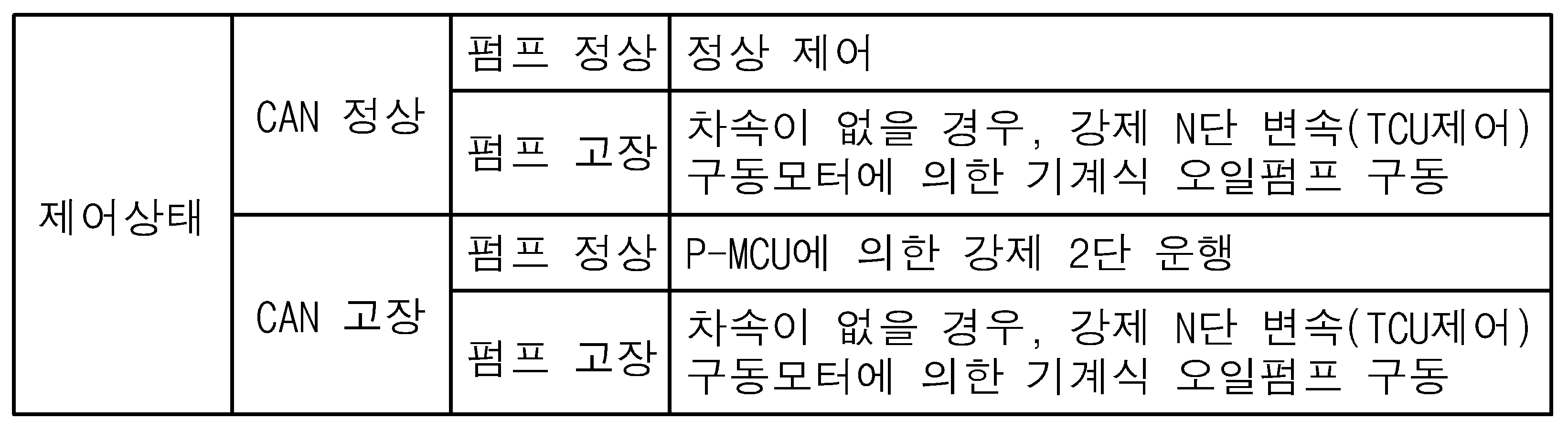
우선, 하이브리드 전기 차량에서 제어기 간 CAN 통신 고장이 검출되고 전동식 오일펌프(6) 및 그 구동용 모터가 정상상태이면, P-MCU(16)에서 오일펌프 구동용 모터를 설정되어 있는 저속(1단) 및 고속(2단) 중에 고속으로 강제 2단 제어하여 작동유 공급이 이루어지도록 하고(도 2에서 (a)상태), CAN 통신 고장상태를 제어기의 메모리에 저장하는 동시에 오일펌프(6)의 운전상태를 운전자에게 통보한다.First, if CAN communication failure between controllers is detected in the hybrid electric vehicle and the
여기서, P-MCU(16)가 자체적으로 CAN 통신 고장을 검출 및 판단하여(차량에서 CAN(Vehicle CAN) 통신 고장은 각 제어기에 의해 통상 검출되고 있음) 오일펌프 구동용 모터를 2단으로 강제 제어하는데, CAN 통신 고장의 경우에 HCU(11)와 P-MCU(16) 간의 통신이 불가하고, 이에 통상적으로 이루어지는 모터 제어, 즉 HCU(11)와의 통신을 통한 오일펌프 구동용 모터의 정상적인 제어(두 제어기의 협조제어에 의한 제어, 저속 및 고속의 선택 구동 제어)를 상기 P-MCU(16)가 수행할 수 없게 되므로, 항상 충분한 작동유가 공급될 수 있는 2단(고속)으로 모터를 강제 구동시킨다. Here, the P-
다음으로, CAN 통신은 정상이지만 오일펌프 구동용 모터(전동식 오일펌프)가 고장상태인 것으로 판단되면, 고장상태를 판단한 P-MCU(16)가 HCU(11)에 모터 고장상태를 전달하고, 모터 고장상태를 전달받은 HCU(11)는 차속센서의 신호로부터 차속 유무를 판단하게 된다.Next, if CAN communication is normal but the oil pump driving motor (electric oil pump) is determined to be in a failure state, the P-
이때, 차속이 없음을 판단한 경우는, P-MCU(16)로부터 고장상태를 인지한 HCU(11)의 지령에 따라 TCU(17)가 자동 변속기의 변속단을 N(중립)단으로 강제 변속 제어한 뒤, MCU(15)가 HCU(11)의 지령에 따라 구동모터(차량 구동용 모터)(4)를 회전시켜, 자동 변속기(5) 내 기계식 오일펌프(7)가 상기 구동모터(4)의 구동에 의해 작동되도록 하고, 이에 기계식 오일펌프(7)에 의해 엔진 클러치(3) 및 자동 변속기(5) 등 시스템에 작동유가 공급되도록 한다(도 2의 (b)상태).At this time, when it is determined that there is no vehicle speed, the
만약, 차속이 있는 경우에는 자동 변속기(5) 내 기계식 오일펌프(7)가 작동되는 상태이므로 충분한 양의 작동유가 엔진 클러치(3) 및 자동 변속기(5) 등 시스템에 공급되기 때문에 문제가 없게 된다(도 2의 (c)상태).If there is a vehicle speed, since the
이와 같이 차속이 있는 경우에는 자동 변속기(5) 내 기계식 오일펌프(7)가 작동되는 상태에서 충분한 양의 작동유가 공급되기 때문에 문제가 없지만, 차속이 없는 경우에는 기계식 오일펌프(7)에 의한 오일 공급이 불충분할 수 있으므로, 자동 변속기(5)의 변속단을 N단으로 변속 제어한 뒤 구동모터(4)를 구동시켜, 구동모터(4)의 구동에 의해 기계식 오일펌프(7)가 작동되도록 하고, 이에 기계식 오일펌프(7)에 의해 충분한 양의 작동유가 공급될 수 있도록 하는 것이다.If there is a vehicle speed in this way, there is no problem because a sufficient amount of hydraulic oil is supplied while the
한편, CAN 통신도 고장이고 오일펌프 구동용 모터도 고장일 때, HCU(11)는 CAN 통신 고장을 자체 검출한 상태에서 P-MCU(16)로부터 CAN 통신과는 별도로 연결된 통신 와이어(18)를 통해 모터 고장상태를 전달받게 된다.On the other hand, when CAN communication fails and the oil pump driving motor also fails, the
그리고, 이에 CAN 통신 및 모터 고장을 인지한 HCU(11)는 차속센서의 신호로부터 차속 유무를 판단하게 된다.In addition, the
이때, 차속이 없음을 판단한 경우는, HCU(11)가 별도로 연결된 통신 와이어(19)를 통해 TCU(17)로 지령하여 TCU(17)로 하여금 자동 변속기(5)의 변속단을 N(중립)단으로 강제 변속 제어하도록 한 뒤, HCU(11)가 별도로 연결된 통신 와이어(21)를 통해 MCU(15)로 지령하여 MCU(15)로 하여금 구동모터(차량 구동용 모터)(4)를 회전시키도록 한다.At this time, when it is determined that there is no vehicle speed, the
이에 자동 변속기(5) 내 기계식 오일펌프(7)가 상기 구동모터(4)의 구동에 의해 작동되도록 하고, 기계식 오일펌프(7)에 의해 엔진 클러치(3) 및 자동 변속기(5) 등 시스템에 작동유가 공급되도록 한다(도 2의 (b)상태).The mechanical oil pump (7) in the automatic transmission (5) is operated by the drive of the drive motor (4), by the mechanical oil pump (7) to the system such as the engine clutch (3) and automatic transmission (5). Allow hydraulic oil to be supplied (state (b) of FIG. 2).
만약, 차속이 있는 경우에는 자동 변속기(5) 내 기계식 오일펌프(7)가 작동되는 상태이므로 충분한 양의 작동유가 엔진 클러치(3) 및 자동 변속기(5) 등 시스템에 공급되기 때문에 문제가 없게 된다(도 2의 (c)상태).If there is a vehicle speed, since the
상기의 제어 과정에서, 차량 내 CAN 통신 고장상태는 각 제어기(11~17)에서 일반적으로 검출되고 있고, 또한 오일펌프 구동용 모터의 고장상태는 특정 제어기, 예컨대 P-MCU(16)가 오일펌프(6)의 목표 회전수와 실제 회전수의 차이가 특정 범위를 벗어날 경우에 펌프 고장상태를 판단하도록 되어 있다.In the above control process, the in-vehicle CAN communication failure state is generally detected in each
물론, 오일펌프 구동용 모터의 고장상태를 판단하는 방법으로서, 오일펌프 구동용 모터의 회전수에 따른 실제 토출 유량을 모니터링하거나, 변속기 제어기의 라인 압력 검출을 통해 판별할 수도 있으며, 다만 이 경우 새로운 하드웨어적 구성요소, 즉 유량센서 혹은 압력센서의 추가 탑재가 필요하게 된다.Of course, as a method of determining a failure state of the oil pump driving motor, the actual discharge flow rate according to the rotation speed of the oil pump driving motor may be monitored or determined by detecting the line pressure of the transmission controller. Additional hardware components, eg flow sensors or pressure sensors, will be required.
이와 같이 하여, 본 발명에 따르면, CAN 통신라인과 전동식 오일펌프의 고장에 대처하기 위한 제어방안이 마련됨으로써, 작동유가 충분히 공급되지 못하여 발생할 수 있는 제반 문제, 즉 엔진 클러치와 변속기의 작동 이상 등을 효과적으로 예방할 수 있게 된다.In this way, according to the present invention, by providing a control scheme for coping with the failure of the CAN communication line and the electric oil pump, various problems that may occur due to insufficient supply of hydraulic oil, that is, the abnormal operation of the engine clutch and the transmission, etc. It can be effectively prevented.
이상에서 설명한 바와 같이, 본 발명에 따른 하이브리드 전기 차량의 캔 통신 및 전동식 오일펌프 고장시 제어방법에 의하면, 캔 통신라인 또는 전동식 오일펌프의 고장시에 변속기와 구동모터의 제어, 전동식 오일펌프의 고속 운행 제어 등을 통하여 엔진 클러치와 변속기에 충분한 양의 작동유가 공급될 수 있도록 함으로써, 작동유가 충분히 공급되지 못하여 발생할 수 있는 엔진 클러치와 변속기의 작동 이상 발생 등을 효과적으로 방지할 수 있게 되는 효과가 있다. As described above, according to the control method of the can communication and the electric oil pump failure of the hybrid electric vehicle according to the present invention, the control of the transmission and the driving motor at the time of the failure of the can communication line or the electric oil pump, the high speed of the electric oil pump By allowing a sufficient amount of hydraulic oil to be supplied to the engine clutch and the transmission through the driving control, etc., it is possible to effectively prevent the occurrence of abnormal operation of the engine clutch and the transmission that may occur due to insufficient supply of the hydraulic oil.
Claims (2)
Priority Applications (1)
| Application Number | Priority Date | Filing Date | Title |
|---|---|---|---|
| KR1020070059673A KR100836308B1 (en) | 2007-06-19 | 2007-06-19 | Control method of hybrid electric vehicle in oil pump/can fail |
Applications Claiming Priority (1)
| Application Number | Priority Date | Filing Date | Title |
|---|---|---|---|
| KR1020070059673A KR100836308B1 (en) | 2007-06-19 | 2007-06-19 | Control method of hybrid electric vehicle in oil pump/can fail |
Publications (1)
| Publication Number | Publication Date |
|---|---|
| KR100836308B1 true KR100836308B1 (en) | 2008-06-09 |
Family
ID=39770546
Family Applications (1)
| Application Number | Title | Priority Date | Filing Date |
|---|---|---|---|
| KR1020070059673A KR100836308B1 (en) | 2007-06-19 | 2007-06-19 | Control method of hybrid electric vehicle in oil pump/can fail |
Country Status (1)
| Country | Link |
|---|---|
| KR (1) | KR100836308B1 (en) |
Cited By (17)
| Publication number | Priority date | Publication date | Assignee | Title |
|---|---|---|---|---|
| KR101000433B1 (en) | 2008-12-05 | 2010-12-13 | 기아자동차주식회사 | Fail safe controlling method of oil pump control unit for hybrid vehicle |
| KR101044234B1 (en) | 2011-05-19 | 2011-06-27 | (주)모토닉 | Method for driving oil pump for plug=in hybrid vehicle |
| KR101044235B1 (en) | 2011-05-19 | 2011-06-27 | (주)모토닉 | Method for driving oil pump for hybrid vehicle |
| KR101044228B1 (en) | 2009-04-01 | 2011-06-27 | (주)모토닉 | Unit for driving oil pump for hybrid vehicle |
| KR101044230B1 (en) | 2009-04-03 | 2011-06-27 | (주)모토닉 | Unit for driving oil pump for stop and go vehicle |
| KR101044233B1 (en) | 2011-05-19 | 2011-06-27 | (주)모토닉 | Method for driving oil pump for stop and go vehicle |
| KR101044231B1 (en) | 2009-04-02 | 2011-06-27 | (주)모토닉 | Unit for driving oil pump for plug=in hybrid vehicle |
| KR101145623B1 (en) | 2009-11-04 | 2012-05-15 | 기아자동차주식회사 | Method for controlling fail safe of hybrid vehicle |
| KR101199320B1 (en) | 2010-02-25 | 2012-11-09 | (주)모토닉 | Unit for driving oil pump for plug-in hybrid vehicle |
| KR101234642B1 (en) * | 2010-12-07 | 2013-02-19 | 기아자동차주식회사 | Limp home controlling systen of hybrid vehicle |
| KR101238761B1 (en) * | 2012-09-21 | 2013-03-06 | (주)모토닉 | Method for driving oil pump for plug-in hybrid vehicle |
| KR101251908B1 (en) * | 2012-10-24 | 2013-04-08 | (주)모토닉 | Method for controling oil pump for plug-in hybrid vehicle |
| KR101274137B1 (en) * | 2012-08-10 | 2013-06-11 | 기아자동차주식회사 | Limp home controlling method of hybrid vehicle |
| KR101307911B1 (en) | 2010-12-06 | 2013-09-13 | (주)모토닉 | Unit for controling oil pump for plug-in hybrid vehicle |
| KR101393584B1 (en) | 2012-12-26 | 2014-05-09 | 현대자동차 주식회사 | Cooling fan monitoring system for fuel cell vehicle and method thereof |
| KR101451130B1 (en) * | 2009-03-09 | 2014-10-15 | 삼성테크윈 주식회사 | Apparatus for controlling electric drive of vehicle and autonomous drive vehicle therewith |
| CN113279950A (en) * | 2021-05-27 | 2021-08-20 | 盛瑞传动股份有限公司 | Control method for electronic oil pump fault diagnosis, electronic device, and storage medium |
Citations (3)
| Publication number | Priority date | Publication date | Assignee | Title |
|---|---|---|---|---|
| US6569054B2 (en) | 2000-04-06 | 2003-05-27 | Jatco Transtechnology, Ltd. | Parallel hybrid vehicle |
| US6616570B2 (en) | 2001-02-20 | 2003-09-09 | Honda Giken Kogyo Kabushiki Kaisha | Control apparatus for hybrid vehicle |
| JP2007131293A (en) * | 2005-11-11 | 2007-05-31 | Hyundai Motor Co Ltd | Fail safety control system between control machines of hybrid vehicle |
-
2007
- 2007-06-19 KR KR1020070059673A patent/KR100836308B1/en not_active IP Right Cessation
Patent Citations (3)
| Publication number | Priority date | Publication date | Assignee | Title |
|---|---|---|---|---|
| US6569054B2 (en) | 2000-04-06 | 2003-05-27 | Jatco Transtechnology, Ltd. | Parallel hybrid vehicle |
| US6616570B2 (en) | 2001-02-20 | 2003-09-09 | Honda Giken Kogyo Kabushiki Kaisha | Control apparatus for hybrid vehicle |
| JP2007131293A (en) * | 2005-11-11 | 2007-05-31 | Hyundai Motor Co Ltd | Fail safety control system between control machines of hybrid vehicle |
Cited By (17)
| Publication number | Priority date | Publication date | Assignee | Title |
|---|---|---|---|---|
| KR101000433B1 (en) | 2008-12-05 | 2010-12-13 | 기아자동차주식회사 | Fail safe controlling method of oil pump control unit for hybrid vehicle |
| KR101451130B1 (en) * | 2009-03-09 | 2014-10-15 | 삼성테크윈 주식회사 | Apparatus for controlling electric drive of vehicle and autonomous drive vehicle therewith |
| KR101044228B1 (en) | 2009-04-01 | 2011-06-27 | (주)모토닉 | Unit for driving oil pump for hybrid vehicle |
| KR101044231B1 (en) | 2009-04-02 | 2011-06-27 | (주)모토닉 | Unit for driving oil pump for plug=in hybrid vehicle |
| KR101044230B1 (en) | 2009-04-03 | 2011-06-27 | (주)모토닉 | Unit for driving oil pump for stop and go vehicle |
| KR101145623B1 (en) | 2009-11-04 | 2012-05-15 | 기아자동차주식회사 | Method for controlling fail safe of hybrid vehicle |
| KR101199320B1 (en) | 2010-02-25 | 2012-11-09 | (주)모토닉 | Unit for driving oil pump for plug-in hybrid vehicle |
| KR101307911B1 (en) | 2010-12-06 | 2013-09-13 | (주)모토닉 | Unit for controling oil pump for plug-in hybrid vehicle |
| KR101234642B1 (en) * | 2010-12-07 | 2013-02-19 | 기아자동차주식회사 | Limp home controlling systen of hybrid vehicle |
| KR101044233B1 (en) | 2011-05-19 | 2011-06-27 | (주)모토닉 | Method for driving oil pump for stop and go vehicle |
| KR101044235B1 (en) | 2011-05-19 | 2011-06-27 | (주)모토닉 | Method for driving oil pump for hybrid vehicle |
| KR101044234B1 (en) | 2011-05-19 | 2011-06-27 | (주)모토닉 | Method for driving oil pump for plug=in hybrid vehicle |
| KR101274137B1 (en) * | 2012-08-10 | 2013-06-11 | 기아자동차주식회사 | Limp home controlling method of hybrid vehicle |
| KR101238761B1 (en) * | 2012-09-21 | 2013-03-06 | (주)모토닉 | Method for driving oil pump for plug-in hybrid vehicle |
| KR101251908B1 (en) * | 2012-10-24 | 2013-04-08 | (주)모토닉 | Method for controling oil pump for plug-in hybrid vehicle |
| KR101393584B1 (en) | 2012-12-26 | 2014-05-09 | 현대자동차 주식회사 | Cooling fan monitoring system for fuel cell vehicle and method thereof |
| CN113279950A (en) * | 2021-05-27 | 2021-08-20 | 盛瑞传动股份有限公司 | Control method for electronic oil pump fault diagnosis, electronic device, and storage medium |
Similar Documents
| Publication | Publication Date | Title |
|---|---|---|
| KR100836308B1 (en) | Control method of hybrid electric vehicle in oil pump/can fail | |
| CN102712314B (en) | Control device and method for vehicle | |
| CN109606351B (en) | Engine starting control method and device, vehicle control unit and vehicle | |
| CN101038032B (en) | On-board hybrid transmission auxiliary-pump priming control system | |
| KR101339233B1 (en) | System and method for determining stop status of hev engine | |
| JP5233725B2 (en) | Control device for electric vehicle | |
| CN103958316B (en) | Start-up strategy for hybrid powertrain | |
| CN107901904B (en) | The control method and hybrid vehicle of hybrid vehicle limp-home | |
| CN102505995B (en) | The controlling method of hybrid electric vehicle engine auto idle speed start and stop and system and device | |
| CN106740826A (en) | A kind of engine starting method and device of single-axle parallel hybrid automobile | |
| CN102039891A (en) | Control apparatus for hybrid vehicle | |
| CN107097779A (en) | The control method and device of hybrid electric vehicle | |
| JP2009035241A (en) | Limp-home mode driving method for hybrid electric vehicle when engine clutch controller fails and engine clutch-control hydraulic device for limp-home driving | |
| CN106585617B (en) | Engine start control method, device and HCU | |
| US10730509B2 (en) | Fail-safe method for parallel hybrid electric vehicle | |
| CN109927703A (en) | A kind of auxiliary oil pump device and control method for hybrid vehicle | |
| CN105298709A (en) | Engine starting control system and control method | |
| CN109017752B (en) | Hybrid electric vehicle and control method thereof | |
| CN103732463A (en) | Hybrid vehicle control device | |
| CN105292101A (en) | Method and system for controlling hybrid vehicle | |
| CN113954817B (en) | Gear shifting method of hybrid electric vehicle, controller and vehicle | |
| US20160090078A1 (en) | Control apparatus for vehicle | |
| JP4235485B2 (en) | Hydraulic diagnosis method for hybrid electric vehicle | |
| US10124797B2 (en) | Method for controlling vehicle in case of oil-pump failure | |
| CN107428334A (en) | Power transmission for motor vehicle driven by mixed power |
Legal Events
| Date | Code | Title | Description |
|---|---|---|---|
| A201 | Request for examination | ||
| E701 | Decision to grant or registration of patent right | ||
| GRNT | Written decision to grant | ||
| FPAY | Annual fee payment |
Payment date: 20130531 Year of fee payment: 6 |
|
| FPAY | Annual fee payment |
Payment date: 20140529 Year of fee payment: 7 |
|
| FPAY | Annual fee payment |
Payment date: 20150529 Year of fee payment: 8 |
|
| LAPS | Lapse due to unpaid annual fee |