KR100791910B1 - Method for predicting the amount of deposit in sewage pipe and sewage pipe monitoring system with function thereof - Google Patents
Method for predicting the amount of deposit in sewage pipe and sewage pipe monitoring system with function thereof Download PDFInfo
- Publication number
- KR100791910B1 KR100791910B1 KR1020070031443A KR20070031443A KR100791910B1 KR 100791910 B1 KR100791910 B1 KR 100791910B1 KR 1020070031443 A KR1020070031443 A KR 1020070031443A KR 20070031443 A KR20070031443 A KR 20070031443A KR 100791910 B1 KR100791910 B1 KR 100791910B1
- Authority
- KR
- South Korea
- Prior art keywords
- depth
- sediment
- sewage
- sewage pipe
- amount
- Prior art date
Links
- 239000010865 sewage Substances 0.000 title claims abstract description 96
- 238000000034 method Methods 0.000 title claims abstract description 25
- 238000012544 monitoring process Methods 0.000 title abstract description 30
- XLYOFNOQVPJJNP-UHFFFAOYSA-N water Substances O XLYOFNOQVPJJNP-UHFFFAOYSA-N 0.000 claims abstract description 15
- 238000012937 correction Methods 0.000 claims abstract description 3
- 239000013049 sediment Substances 0.000 claims description 61
- 238000004062 sedimentation Methods 0.000 claims description 34
- 230000008021 deposition Effects 0.000 claims description 23
- 238000004088 simulation Methods 0.000 claims description 18
- 238000004364 calculation method Methods 0.000 claims description 10
- 238000005259 measurement Methods 0.000 claims description 9
- 238000013277 forecasting method Methods 0.000 claims description 2
- 238000004458 analytical method Methods 0.000 description 13
- 230000006870 function Effects 0.000 description 10
- 238000009825 accumulation Methods 0.000 description 8
- 238000012423 maintenance Methods 0.000 description 5
- 238000004891 communication Methods 0.000 description 4
- 238000007726 management method Methods 0.000 description 4
- 230000000737 periodic effect Effects 0.000 description 4
- 238000007405 data analysis Methods 0.000 description 3
- 238000010586 diagram Methods 0.000 description 2
- 239000003344 environmental pollutant Substances 0.000 description 2
- 231100000719 pollutant Toxicity 0.000 description 2
- 238000003860 storage Methods 0.000 description 2
- 238000011179 visual inspection Methods 0.000 description 2
- 230000031018 biological processes and functions Effects 0.000 description 1
- 230000005540 biological transmission Effects 0.000 description 1
- 238000010276 construction Methods 0.000 description 1
- 238000007796 conventional method Methods 0.000 description 1
- 230000001186 cumulative effect Effects 0.000 description 1
- 230000001419 dependent effect Effects 0.000 description 1
- 230000000694 effects Effects 0.000 description 1
- 230000007613 environmental effect Effects 0.000 description 1
- 238000011835 investigation Methods 0.000 description 1
- 230000007774 longterm Effects 0.000 description 1
- 230000007257 malfunction Effects 0.000 description 1
- 238000004519 manufacturing process Methods 0.000 description 1
- 238000002360 preparation method Methods 0.000 description 1
- 230000008439 repair process Effects 0.000 description 1
- 239000004576 sand Substances 0.000 description 1
- 238000005204 segregation Methods 0.000 description 1
- 239000002689 soil Substances 0.000 description 1
- 238000012546 transfer Methods 0.000 description 1
- 238000012795 verification Methods 0.000 description 1
- 239000003643 water by type Substances 0.000 description 1
Images


Classifications
-
- G—PHYSICS
- G06—COMPUTING; CALCULATING OR COUNTING
- G06Q—INFORMATION AND COMMUNICATION TECHNOLOGY [ICT] SPECIALLY ADAPTED FOR ADMINISTRATIVE, COMMERCIAL, FINANCIAL, MANAGERIAL OR SUPERVISORY PURPOSES; SYSTEMS OR METHODS SPECIALLY ADAPTED FOR ADMINISTRATIVE, COMMERCIAL, FINANCIAL, MANAGERIAL OR SUPERVISORY PURPOSES, NOT OTHERWISE PROVIDED FOR
- G06Q50/00—Information and communication technology [ICT] specially adapted for implementation of business processes of specific business sectors, e.g. utilities or tourism
- G06Q50/06—Energy or water supply
-
- G—PHYSICS
- G01—MEASURING; TESTING
- G01N—INVESTIGATING OR ANALYSING MATERIALS BY DETERMINING THEIR CHEMICAL OR PHYSICAL PROPERTIES
- G01N21/00—Investigating or analysing materials by the use of optical means, i.e. using sub-millimetre waves, infrared, visible or ultraviolet light
- G01N21/84—Systems specially adapted for particular applications
- G01N21/88—Investigating the presence of flaws or contamination
-
- G—PHYSICS
- G06—COMPUTING; CALCULATING OR COUNTING
- G06Q—INFORMATION AND COMMUNICATION TECHNOLOGY [ICT] SPECIALLY ADAPTED FOR ADMINISTRATIVE, COMMERCIAL, FINANCIAL, MANAGERIAL OR SUPERVISORY PURPOSES; SYSTEMS OR METHODS SPECIALLY ADAPTED FOR ADMINISTRATIVE, COMMERCIAL, FINANCIAL, MANAGERIAL OR SUPERVISORY PURPOSES, NOT OTHERWISE PROVIDED FOR
- G06Q10/00—Administration; Management
- G06Q10/20—Administration of product repair or maintenance
-
- G—PHYSICS
- G06—COMPUTING; CALCULATING OR COUNTING
- G06Q—INFORMATION AND COMMUNICATION TECHNOLOGY [ICT] SPECIALLY ADAPTED FOR ADMINISTRATIVE, COMMERCIAL, FINANCIAL, MANAGERIAL OR SUPERVISORY PURPOSES; SYSTEMS OR METHODS SPECIALLY ADAPTED FOR ADMINISTRATIVE, COMMERCIAL, FINANCIAL, MANAGERIAL OR SUPERVISORY PURPOSES, NOT OTHERWISE PROVIDED FOR
- G06Q50/00—Information and communication technology [ICT] specially adapted for implementation of business processes of specific business sectors, e.g. utilities or tourism
- G06Q50/10—Services
- G06Q50/26—Government or public services
Landscapes
- Business, Economics & Management (AREA)
- Engineering & Computer Science (AREA)
- Tourism & Hospitality (AREA)
- Economics (AREA)
- Human Resources & Organizations (AREA)
- Health & Medical Sciences (AREA)
- Physics & Mathematics (AREA)
- General Physics & Mathematics (AREA)
- Marketing (AREA)
- General Health & Medical Sciences (AREA)
- Strategic Management (AREA)
- General Business, Economics & Management (AREA)
- Theoretical Computer Science (AREA)
- Primary Health Care (AREA)
- Quality & Reliability (AREA)
- Pathology (AREA)
- Chemical & Material Sciences (AREA)
- Analytical Chemistry (AREA)
- Biochemistry (AREA)
- Operations Research (AREA)
- Immunology (AREA)
- Life Sciences & Earth Sciences (AREA)
- Public Health (AREA)
- Water Supply & Treatment (AREA)
- Entrepreneurship & Innovation (AREA)
- Development Economics (AREA)
- Educational Administration (AREA)
- Sewage (AREA)
- Management, Administration, Business Operations System, And Electronic Commerce (AREA)
Abstract
Description
도 1은 본 발명에 따른 하수관거내 퇴적량 예측이 가능한 하수관거 모니터링 시스템의 주요구성도.1 is a main configuration of the sewage pipe monitoring system capable of predicting sediment accumulation amount in the sewage pipe according to the present invention.
도 2는 본 발명에 따른 퇴적량 예측이 가능한 하수관거 모니터링 시스템에서의 실측 퇴적량 조회 결과화면을 나타낸 도면.Figure 2 is a view showing the actual amount of sediment inquiry result screen in sewage monitoring system capable of predicting the amount of sediment according to the present invention.
도 3은 본 발명에 따른 퇴적량 예측이 가능한 하수관거 모니터링 시스템에서의 퇴적량 예측 모의 해석시의 차분격자망을 나타낸 도면.Figure 3 is a diagram showing the differential grid in the sediment amount prediction simulation analysis in sewage pipe monitoring system capable of sediment amount prediction according to the present invention.
도 4는 본 발명에 따른 시계열 모의를 이용한 퇴적량 예측 모의방법을 통한 장래 일정기간 동안의 지점별 하수관거 퇴적량 변화추이의 일실시예를 나타낸 도면.Figure 4 is a view showing an embodiment of the sewage sediment deposition change trend for each point for a certain period in the future through the sediment prediction simulation method using a time series simulation in accordance with the present invention.
도 5는 본 발명에 따른 퇴적량 예측이 가능한 하수관거 모니터링 시스템이 SWMM과 연계하여 해당지점의 퇴적량을 분석하는 화면을 나타낸 도면.5 is a view showing a screen for analyzing the sedimentation amount of the corresponding point in conjunction with the SWMM sewage pipe monitoring system capable of predicting the sedimentation amount according to the present invention.
* 도면의 주요부분에 대한 부호의 설명 *Explanation of symbols on the main parts of the drawings
100-100n: 현장제어반 200: DSU100-100n: Field control panel 200: DSU
300: 터미널 서버 400: 스위칭 허브300: terminal server 400: switching hub
500: DB연산 서버 600: 관리분석 서버500: DB operation server 600: management analysis server
700: 운영 서버700: production server
본 발명은 하수관거내 퇴적량 예측방법 및 그 기능을 탑재한 하수관거 모니터링 시스템에 관한 것으로, 보다 상세하게는 퇴적심도계에 의한 정량화된 퇴적량 데이터베이스 구축 및 하수관거 자료분석에 사용될 수 있는 프로그램과의 연계활용을 통하여 유지관리가 필요한 해당 하수관거의 특정시기의 퇴적량과 적정 준설시기를 예측가능하도록 지원함으로써, 종래의 주기적인 하수관거 준설작업에 비해 준설비용을 절감할 수 있고, 정량화된 퇴적량 데이터베이스 구축 및 그 분석작업을 통하여 간접적으로 하수관거의 구배 및 지역적 특성이 하수관거 퇴적량에 미치는 영향을 파악할 수 있도록 지원하는 하수관거내 퇴적량 예측방법 및 그 기능을 탑재한 하수관거 모니터링 시스템에 관한 것이다.The present invention relates to a sewage sediment prediction method and a sewage sewer monitoring system equipped with the function thereof, and more specifically, to utilize a program that can be used to establish a quantitative sediment amount database by sedimentation depth meter and analyze sewage data. By supporting the predictable amount of sediment and proper dredging time of the relevant sewage pipes that need maintenance through the project, it is possible to save the use of the quarry facility compared to the conventional periodic sewage pipe dredging work, and establish a quantitative amount of sediment database. The present invention relates to a sewage sediment estimating method and a sewage sewer monitoring system equipped with the function to assist indirectly grasping the influence of the sewage segregation and regional characteristics on sewage sediment deposition through analysis.
일반적으로, 하수관거 모니터링 시스템은 관리자가 근무하는 하수처리장 중앙감시반 내부에 설치되어 관리·운영되며, 계측자료 전송부분과 시스템 내부DB환 경 및 시스템 운영환경으로 크게 나뉘어진다.In general, the sewage pipe monitoring system is installed and managed inside the central monitoring panel of the sewage treatment plant where the manager works. The sewage pipe monitoring system is largely divided into the measurement data transmission part, the system DB environment, and the system operating environment.
또한, 전기전도도계·유량계와 같은 현장계측기는 현장수질부분과 유량계측 시스템으로 나뉘어지고, 현장계측자료는 원거리의 DB서버로 송신됨과 동시에 메모리내 저장 혹은 주기적 백업과정을 거쳐 관리되어지며, 하수관거 모니터링 시스템 내부의 관리분석서버는 이들 자료의 검증성 확보 및 신뢰도 검토를 수행 후 기구축된 분구별 기초자료(하수도 시설물 현황, CCTV자료 등)와 병행한 자료분석을 실시하게 된다. 이런 분석결과를 기초로 하여 하수관거의 I/I·누수정도·성과보증 정도가 검토가능하고, 통수능 평가 및 침수예측의 기초자료를 제공함으로써 향후 유지관리 계획 및 보수를 위한 기초자료를 제공하는 것이 통상적인 하수관거 모니터링 시스템의 기본 목적이다.In addition, on-site instruments such as conductivity meters and flow meters are divided into on-site water quality and flow measurement systems, and the on-site measurement data are sent to a remote DB server and managed through storage in memory or periodic backup process. The management analysis server in the system conducts data analysis in parallel with the basic data (sewage facility status, CCTV data, etc.) for each classified section after securing verification and reliability of these data. Based on the results of this analysis, I / I, leakage level, and performance guarantee level of sewage pipes can be reviewed, and it is common to provide basic data for future maintenance plans and repairs by providing basic data for evaluating water capacity and predicting flooding. This is the basic purpose of the sewage monitoring system.
한편, 하수관거는 해당유역의 오수를 하수처리장으로 이송하고 우수는 공공수역으로 방류하는 환경기초시설이고, 이런 하수관거는 지하에 매설되어 시공되기 때문에 일단 시공한 후에는 하수관거내의 상태를 파악하기 쉽지 않은데, 종래의 하수관거내의 상태를 조사하는 방법으로는 육안으로 조사하거나 CCTV 촬영장비를 하수관거 내부를 촬영하거나 기계식 측정장비를 사용하였다.On the other hand, sewage pipe is an environmental foundation facility that transfers sewage from the watershed to the sewage treatment plant, and rainwater is discharged to public waters.These sewage pipes are buried underground, so it is not easy to grasp the state of the sewage pipes after construction. As a conventional method for investigating the condition in sewage pipes, visual inspection or CCTV equipment was used to photograph the inside of sewage pipes or mechanical measuring equipment was used.
그러나, 상기 육안으로 조사하는 방법은 맨홀 등을 통해 하수관거의 내부로 들어가 하수관거 내부의 상태나 퇴적물의 양을 육안으로 조사하거나 측정하는 것으로서 사람의 육감에 의존하게 되므로 정밀성이나 신뢰성이 떨어지고, CCTV 촬영장비를 이용하는 방법은 촬영한 화면으로 결국은 사람이 판단해야 하므로 이 역시 그 정확도가 떨어지는 것은 당연하며, 기계식 측정장비를 이용하는 방법도 하수관거의 관경별로 그에 맞는 각각의 측정장비를 구비해야할 뿐만 아니라 기기작동도 어려운 문제점이 있었다.However, the visual inspection method is to enter the inside of the sewer pipe through a manhole or the like to visually inspect or measure the state of the sewer pipe or the amount of sediment, so it is dependent on the human sixth sense. Since the method of using a photographed screen is ultimately determined by a person, it is natural that the accuracy is also lowered. The method of using a mechanical measuring device also has to be equipped with a respective measuring device for each diameter of the sewage pipe as well as the operation of the device. There was a difficult problem.
한편, 일정기간 동안 하수 등이 유입된 하수관거에 적정하수유속의 미확보 및 하수관거의 역구배 등으로 인한 토사 및 퇴적물이 일정량이상 쌓이게 되면 하수관거의 통수능 확보를 위해 준설작업이 이루어져야 하고, 이런 준설작업은 일반적으로 하수관거내의 퇴적물을 준설하기 위하여 준설용 대차와 윈치 및 지상의 펌프를 이용하게 되는데, 여기서 준설용 대차를 밀어내어 하수차집관거 바닥에 쌓인 퇴적물을 하수차집관거의 맨홀 침사지에 쌓은 다음 흡입관을 통해 침사지에 쌓인 퇴적물을 흡입하여 제거하게 되는 것이다. 구체적으로 맨홀을 통해 수직관로 안으로 흡입관을 삽입하여 설치하고 지상의 준설차와 연결된 지상의 펌프와 결합시키며 수직관로에는 지지프레임을 설치한다. 지지프레임의 소정위치에는 지지롤러가 구비되고 지상의 윈치로부터 연장된 로프는 지지롤러를 거쳐 하수관거내에 설치된 대차와 결합하며, 지상의 윈티를 회전시켜 로프를 당기면 대차가 이동하면서 하수차집관거 내의 퇴적물을 맨홀 침사지로 밀어서 이동시키고, 그 다음으로 맨홀 침사지에 쌓인 퇴적물은 흡입관을 통해 지상으로 이송되게 된다.On the other hand, if sediment and sediment accumulate due to inadequate sewage flow rate and sedimentation of sewage pipes in sewage pipes where sewage flows into the sewage pipe during a certain period, dredging work should be carried out to secure the water supply capacity of sewage pipes. In order to dredge the sediment in the sewer pipe, dredging bogie, winch and ground pump are used. Sediment is sucked and removed. Specifically, the suction pipe is inserted into the vertical pipe through the manhole, installed and coupled with the ground pump connected to the dredging car on the ground, and the support frame is installed in the vertical pipe. At a predetermined position of the support frame, a support roller is provided, and the rope extending from the winch on the ground is coupled with the trolley installed in the sewage pipe via the support roller, and when the rope is pulled by rotating the winty on the ground, the trolley moves and manholes in the sewer pipe are deposited. The sediment is then pushed to the settlement and the sediment accumulated in the manhole settlement is transported to the ground through the suction pipe.
이처럼 적지않은 인력과 장비가 투입되는 일련의 준설작업들이 종래에는 하수관거 모니터링 시스템의 지원 기능이 없는 상태에서 상기와 같은 별도의 하수관거내 상태 조사방법에 의한 후 또는 주기적으로 이루어져 하수관거내의 퇴적량을 측정할 때마다 인원과 장비를 투입해야 하거나 적절하고 효율적인 준설시기를 예측하기 힘들었는데, 이런 이유로 종국에는 준설시기가 아직 아닌데도 준설을 하여 시 간과 비용을 낭비하거나 준설시기를 놓쳐 하수의 통수능 확보가 지연되거나 적시의 준설보다 훨씬 더 많은 시간과 비용이 소요되는 경우가 빈번하였다.As such, a series of dredging operations in which a lot of manpower and equipment are input is conventionally performed after or separately from the sewer conduit condition survey method without the support function of the sewer conduit monitoring system to measure the amount of sedimentation in the sewer conduit. It was difficult to predict the appropriate and efficient dredging time every time, and for this reason, dredging was not yet in the dredging time, but wasted dredging time and cost or missed dredging time, delaying or timely securing sewage capacity. It was often more time and cost than dredging.
본 발명은 상기와 같은 문제점을 해결하기 위해 안출된 것으로, 본 발명의 목적은 퇴적심도계에 의한 정량화된 퇴적량 데이터베이스 구축 및 하수관거 자료분석에 사용될 수 있는 프로그램과의 연계활용을 통하여 유지관리가 필요한 해당 하수관거의 특정시기의 퇴적량과 적정 준설시기를 예측가능하도록 지원함으로써, 종래의 주기적인 하수관거 준설작업에 비해 준설비용을 절감할 수 있는 하수관거내 퇴적량 예측방법 및 그 기능을 탑재한 하수관거 모니터링 시스템을 제공하는 데 있다.The present invention has been made to solve the above problems, the object of the present invention is to establish a quantitative deposition amount database by sedimentation depth meter and the need for maintenance through the linkage with the program that can be used for sewage pipe data analysis By supporting predictable amount of sediment and appropriate dredging time of the sewage pipe, the sewage pipe monitoring system and sewage monitoring system equipped with the sediment forecasting method and its function can save the dredging facility compared with the conventional periodic sewer dredging work. To provide.
또한, 본 발명의 다른 목적은 정량화된 퇴적량 데이터베이스 구축 및 그 분석작업을 통하여 간접적으로 하수관거의 구배 및 지역적 특성이 하수관거 퇴적량에 미치는 영향을 파악할 수 있도록 지원하는 하수관거내 퇴적량 예측방법 및 그 기능을 탑재한 하수관거 모니터링 시스템을 제공하는 데 있다.In addition, another object of the present invention is to establish a quantitative deposition database and its analysis work indirectly to estimate the sedimentation sediment accumulation amount and the function of the sewer pipe drainage and regional characteristics on sewage sediment deposition and its function It is to provide a sewage pipe monitoring system equipped with.
상기와 같은 목적을 달성하기 위하여, 본 발명은 퇴적심도계를 활용한 현장제어반(100-100n)을 통하여 하수관거내 지점별 실측된 퇴적심도 자료를 전송하는 단계와; 상기 전송된 퇴적심도 자료를 기초로 하면서 하수관거 자료분석 프로그램 인 SWMM과 연계하여 하수관거내 퇴적량을 예측 모의하는 단계로 구성된 것을 그 기술적 구성상의 기본 특징으로 하는 하수관거내 퇴적량 예측방법 및 그 기능을 탑재한 하수관거 모니터링 시스템을 제공한다. In order to achieve the above object, the present invention comprises the steps of transmitting the measured sedimentation depth data for each point in the sewage pipe through the field control panel (100-100n) using the sedimentation depth meter; Based on the transmitted sediment depth data, and in connection with SWMM, the sewage sewer data analysis program, the seismic sediment amount prediction method and its function, which is composed of the steps of predicting and estimating sediment in sewage sediment, are characterized by its technical features. Provide a sewage monitoring system.
상기와 같이 구성된 본 발명의 바람직한 실시예를 첨부된 도면을 참조하면서 상세히 설명하면 다음과 같다.When described in detail with reference to the accompanying drawings a preferred embodiment of the present invention configured as described above are as follows.
도 1은 본 발명에 따른 하수관거내 퇴적량 예측이 가능한 하수관거 모니터링 시스템의 주요구성도이고, 도 2는 본 발명에 따른 퇴적량 예측이 가능한 하수관거 모니터링 시스템에서의 실측 퇴적량 조회 결과화면을 나타낸 도면이며, 도 3은 본 발명에 따른 퇴적량 예측이 가능한 하수관거 모니터링 시스템에서의 퇴적량 예측 모의 해석시의 차분격자망을 나타낸 도면이고, 도 4는 본 발명에 따른 시계열 모의를 이용한 퇴적량 예측 모의방법을 통한 장래 일정기간 동안의 지점별 하수관거 퇴적량 변화추이의 일실시예를 나타낸 도면이며, 도 5는 본 발명에 따른 퇴적량 예측이 가능한 하수관거 모니터링 시스템이 SWMM과 연계하여 해당지점의 퇴적량을 분석하는 화면을 나타낸 도면이다.1 is a main configuration of the sewage pipe monitoring system capable of predicting the sediment accumulation amount in the sewage pipe according to the present invention, Figure 2 is a view showing a measurement result inquiry screen in the sewage pipe monitoring system capable of predicting the sediment amount according to the present invention. 3 is a diagram showing a differential sequential network when analyzing sediment amount prediction simulation in sewage monitoring system capable of predicting sediment amount according to the present invention, and FIG. 4 shows a sediment amount prediction simulation method using time series simulation according to the present invention. Figure 1 is a view showing an embodiment of the change of sewage sediment accumulation amount by point for a certain period of time through the future, Figure 5 is a sewage sediment monitoring system capable of predicting the sediment amount according to the present invention in conjunction with SWMM to analyze the sediment amount of the corresponding point The figure shows the screen.
도 1에 도시된 바와 같이, 본 발명의 하수관거 모니터링 시스템은 퇴적심도 측정지점으로 선정된 주요 하수관거에 설치되어 퇴적심도를 일정 주기 또는 시스템 운영자의 요청시에 계측 송신하는 퇴적심도계와 상기 퇴적심도계를 통하여 계측된 퇴적심도 자료들이 컴퓨터들과 관련 장치들 간의 직렬 데이터 통신을 위한 RS통신을 통하여 전송되는 현장제어반(100-100n)내의 컨트롤러와 상기 현장제어반(100- 100n)내의 컨트롤러로 전송된 자료들이 DSU 또는 CDMA모뎀 등을 통해 KT전용선 등의 유·무선 통신망을 거쳐 하수관거 모니터링 시스템의 DSU(200)로 실시간 전송되고, 다시 상기 전송된 자료들이 터미널 서버(300)와 스위칭 허브(400)에 의한 자료교환을 수행하며 해당 하수관거 지점별로 정량화된 퇴적량 자료로 데이터베이스화되게 하는 하수관거 모니터링 시스템 내부의 DB연산 서버(500)와 이런 퇴적심도 자료를 기초로 하여 일정구간 하수관거내 퇴적량을 분석·예측 모의 하는 관리분석 서버(600) 및 운영서버(700)로 구성된다.As shown in Figure 1, the sewage pipe monitoring system of the present invention is installed in the main sewage pipe selected as the sedimentation depth measurement point sedimentation depth meter and the sedimentation depth meter to measure and transmit the sedimentation depth at the request of the system operator or a certain period Sedimentation depth data measured through the data transmitted to the controller in the field control panel (100-100n) and the controller in the field control panel (100-100n) is transmitted through the RS communication for serial data communication between computers and related devices Are transmitted in real time to the DSU 200 of the sewage pipe monitoring system via a wired / wireless communication network such as a KT dedicated line through a DSU or a CDMA modem, and the transmitted data are transmitted by the
한편, 퇴적심도계에서 전송되어 오는 퇴적심도 자료들은 기기의 오작동 또는 통신망의 오류 등으로 일부 보정이 필요한 경우가 있을 수 있으며, 상기 운영서버(700)에는 하수관거 자료분석에 사용될 수 있는 범용 프로그램인 SWMM(Storm Water Management Model)이 설치되는데, 상기 SWMM은 원래 도시유역내에서 강우사상으로 인해 발생하는 유출량과 오염물질에 대한 지표면 및 지표하 흐름, 배수관망에서의 유출량 추적, 저류량 산정, 오염물질의 처리와 비용계산 등을 모의할 수 있고, 다양한 토지이용현황을 고려해서 유역의 출구와 하수관거 혹은 수로에서의 유출량과 수질을 예측할 수 있으며, 단일 강우사상을 물론 연속적인 모의도 가능한 프로그램으로서, 유량계산은 매우 상세하고 관측치와 잘 일치하는 결과를 보여주는 반면, 수질계산은 실제의 물리적, 화학적, 생물학적 과정을 제대로 나타내지 못하여 관측치와 차이가 있을 수 있다.Meanwhile, the sedimentation depth data transmitted from the sedimentation depth meter may need to be partially corrected due to a malfunction of a device or an error of a communication network, and the
또한, 퇴적심도계를 통하여 계측된 퇴적심도 자료들과 SWMM을 이용하여 하수관거내 퇴적량을 예측 모의하기 위한 선행작업으로 해당하수관거 지점부에 대한 장 기강우유출해석과 년간 유입토사예측(RUSLE Model 등) 및 토사입경조사가 이루어져야하는데, 이는 SWMM을 사용할 때 일반적인 사항이므로 구체적 설명은 생략한다.In addition, as a preliminary work to predict the sedimentation amount in sewage pipes using SWMM and sedimentation depth data measured through sedimentation depth meter, long-term rainfall outflow analysis for the sewage point and annual inflow soil forecasting (RUSLE Model, etc.) ) And earth and sand size investigation should be done, which is a general matter when using SWMM, so a detailed description thereof will be omitted.
따라서, 본 발명은 이런 SWMM내에 퇴적량 예측기능을 탑재한 하수관거 모니터링 시스템을 통해 하수관거내 퇴적량을 예측가능하도록 활용하게 된다.Accordingly, the present invention utilizes the sewage sedimentation monitoring system equipped with the sediment amount prediction function in the SWMM so as to predict the sedimentation amount in the sewage pipe.
즉, 시스템 운영자는 도 2에 도시된 바와 같이, 본 발명의 하수관거 모니터링 시스템에 의해 측정지점별 실측 퇴적량을 조회하기 위해 측정지점 및 조회기간을 설정함으로써 조회 조건에 해당되는 퇴적량 정보를 그래프와 표로 확인할 수 있고, 현장에서 유량계와 퇴적심도계를 통하여 전송되어 오는 유량과 퇴적심도 자료를 하수관거 지점별 특성을 파악하는 기초자료로 활용하여 퇴적량 예측 모의시 SWMM 연산계수의 보정인자를 조정하게 되고, 이를 통해 퇴적심도를 포함하는 장래의 수심(h1)을 예측할 수 있으며, 상기 실측된 퇴적량 자료를 통한 SWMM 모의계수 조정이 완료되면 퇴적량 예측 모의를 수행할 준비가 완료되게 되는 것이다.That is, as shown in FIG. 2, the system operator sets the measurement point and the inquiry period in order to inquire the actual deposition amount for each measurement point by the sewage pipe monitoring system of the present invention, and displays the deposition amount information corresponding to the inquiry condition with the graph. As a basic data to identify characteristics of sewage pipes, the correction factor of SWMM calculation coefficient is adjusted when the sediment forecast is simulated. In this way, it is possible to predict the future depth (h 1 ) including the depth of sedimentation, and when the SWMM simulation coefficient adjustment is completed through the measured sedimentation amount data, the preparation of the sediment amount prediction simulation is completed.
또한, SWMM을 통한 퇴적량 예측 모의에서 퇴적량 없는 순수 수심(h2)의 연산 수행에 사용되는 주요 지배방정식은 아래의 Manning식과 연속방정식으로 구성된다.In addition, the main governing equations used to perform the calculation of pure water depth (h 2 ) without sediment amount in the simulation of sediment amount estimation through SWMM are composed of the following Manning and continuous equations.
![]()
![]()

여기서, S 0 는 관로의 경사, A는 흐름 단면적, R는 동수반경, n은 관이 조도계수, Q는 유량 그리고 t는 시간을 나타낸다.Where S 0 Is the slope of the pipe, A is the flow cross section, R is the hydraulic radius, n is the roughness coefficient of the pipe, Q is the flow rate, and t is the time.
상기 수학식 1과 수학식 2에서의 흐름은 정상흐름으로 간주되고, 두 수학식의 차분해석을 통하여 미지수인 단면내 Q와 A를 해석시간 경과 후에 대하여 지점별로 산출하게 되며, 실측 퇴적량 자료를 기초로 하여 시스템 운영자는 해당 하수관거 지점별 현재 또는 장래의 퇴적량과 적정 준설시기를 판단가능하게 된다.The flows in
상기 두 수학식의 차분해석에 따른 상세 해석과정을 살펴보면 다음과 같다.Looking at the detailed analysis process according to the difference between the two equations as follows.
우선, 도 3에 도시된 바와 같이, 기지유량값이 Q인 위치 j에서의 단면적은 Aj 이고, Aj 는 수학식 1과 기지유량값 Qj 로부터 구할 수 있으며, 관거 하류부의 위치를 j+1이라 가정하고, 시간차분의 현 기지시간대는 첨자 n으로 표시하고 다음 시간대는 n+1로 한다.First, as shown in Fig. 3, the cross-sectional area at position j at which the known flow rate value is Q is A j , A j can be obtained from
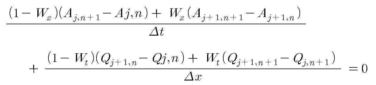
그 다음, 차분해석시이 가중치로 j+1위치의 가중치를 Wx, n+1시간 간격에서의 가중치를 Wt로 가정하여 연속방정식을 차분해석하면 수학식 3과 같다.Next, when the differential equation is sequentially analyzed by assuming that the weight of j + 1 position is Wx and the weight at n + 1 time interval is Wt, the equation is differentially calculated.

여기서, Qj,n , Aj,n 은 기지값이고, 정상흐름에서 시간의 변동없이 유하흐름방향만의 유량변화를 가정할 경우 수학식 2의 연속방정식에서 j+1지점에서의 Qj+1,n 을 알 수 있으며, Qj+1,n 을 알게 되면, 정상흐름임을 가정할 때 에너지 라인이 곧 관로경사와 일치하는 점을 감안할 때, 조도계수 n과 관로경사 S 0 를 기지값으로 알고 있으므로 수학식 1을 통하여 Aj+1,n 을 구할 수 있다, 마찬가지로 유하흐름의 변동없이 시간의 변화만을 가정할 경우 n+1시간 경과 후의 Aj,n+1 을 알 수 있고, 정상흐름조건 하에서 유량값인 Qj,n+1 을 수학식 1을 통하여 구할 수 있다.
시간 n+1흐름 후의 유하방향 위치 j+1에서의 유량과 면적에 해당하는 Qj+1,n+1 과 Aj+1,n+1 을 알기 위해, 위 수학식 3의 각 항에 대하여 △x/Wt를 곱하여 정리하고, 미지수 Q와 A는 각각 관거 만관(滿管)시의 유량, 면적에 대한 비율로 무차원화하여 Q*(=Q/Qf), A*(=A/Af)로 정의 후, 수학식 3에 적용하면 다음과 같은 간편화된 식을 얻을 수 있다.Here, Q j, n , A j, n are known values, and Q j + at the point j + 1 in the continuous equation of
In order to know Q j + 1, n + 1 and A j + 1, n + 1 corresponding to the flow rate and area at the downstream position j + 1 after the time n + 1 flow , Multiply by Δx / Wt and determine the unknown Q and A by dimensioning the flow rate and area at the time of pipe drainage, respectively Q * (= Q / Q f ), A * (= A / A After the definition as f ), it can be applied to
![]()
![]()
여기서, C1은 면적과 유량의 함수로 나타내고, C2는 Q* 와 A* 로 정리된 계수들로서 각 시간대에서의 기지값들이다.Where C 1 is a function of area and flow rate, and C 2 is Q * and Coefficients arranged by A * , which are known values in each time zone.
즉, 

상기 수학식들에서의 흐름은 정상등류로 가정하여 계산이 수행되었으므로 Manning공식에서 Q/Qf 와 A/Af 는 1차 함수관계가 성립되고, 이에 미지수인 Qj+1,n+1 과 Aj+1,n+1 를 수학식 4와 무차원 유출량-면적(Q/Qf - A/Af)관계, 즉 Manning공식으로부터 구할 수 있게 되는 것이다.
상기 방법을 통해 하수관거내 원하는 지점에서의 현재 또는 장래의 흐름 단면적 A를 알 수 있고, 면적산출식의 역산을 통하여 수심 h2 를 예측할 수 있는데, 여기서 h2 는 퇴적량없는 순수 수심이다. 따라서, 하수관거 지점별 현재 또는 장래의 퇴적심도(h)는 상호 대응하는 지점과 시간에서의 상기 h1 과 h2 와의 차이값을 통해 판단가능하게 되는 것이다.Since the calculations were performed under the assumption that the flow in the above equations is normal equality, the first-order functional relationship between Q / Q f and A / A f is established in Manning's equation, and Q j + 1, n + 1 is unknown. And A j + 1, n + 1 can be obtained from Equation 4 and the dimensionless outflow-area (Q / Q f -A / A f ) relationship, that is, the Manning equation.
Through this method it is possible to know the current or future flow cross-sectional area A at the desired point in the sewage pipe, and to predict the depth h 2 through the inversion of the area calculation equation, where h 2 is the pure water depth without deposition amount. Therefore, the current or future deposition depth (h) for each sewage pipe point can be determined through the difference between h 1 and h 2 at the corresponding points and time.
상기 SWMM을 이용한 퇴적량 예측 모의는 지점별 하수관거의 만관(滿管)대비 퇴적량을 비율로 설정하여 모의하는 방법과 예측기간 설정을 통한 시간 경과에 따른 퇴적량을 모의하는 방법으로 구분될 수 있다Sediment amount prediction simulation using SWMM can be divided into a method of simulating the sedimentation amount of the sewage pipes per branch and the amount of sedimentation over time by setting the prediction period.
먼저, 퇴적량 비율 설정 모의방법은 본 발명의 하수관거 모니터링 시스템 운 영자가 지점별 퇴적물 준설시기의 판단자료로 하수관거의 만관(滿管)대비 퇴적량 비율을 설정하여 모의하는 방법으로써, 예를 들면 준설이 필요한 만관대비 퇴적량 비율을 10%로 설정할 경우, 퇴적량 예측 모의 결과가 10%이상을 나타내면 해당 하수관거 지점부는 주기적인 준설시기가 도래하지 않았어도 퇴적량 준설을 시행할 필요가 있는 것으로 운영자가 판단할 수 있도록 본 발명인 하수관거 모니터링 시스템이 적당한 경고를 하는 방법이다.First, the sediment ratio setting simulation method is a method in which the sewage pipe monitoring system operator of the present invention sets the sediment amount ratio to the total pipe of sewage pipe as a judgment data of the sediment dredging time of each point, for example, dredging If the required sediment ratio to 10% is set to 10%, if the simulation result shows 10% or more, the sewerage branch part needs to perform sediment dredging even if the periodic dredging time has not arrived. This is how the present inventors sewer pipe monitoring system to give a proper warning.
예측기간 설정을 통한 퇴적량 모의방법은 일반적인 시계열 모의와 유사한 형태로서, 하수관거 유지관리대상 지점별로 현장에서 전송되어 온 퇴적심도의 보정을 마친 후, 장래 일정기간 동안 지점별 하수관거 퇴적량 변화추이를 도 4에 도시된 바와 같이 운영자가 화면상에서 그래프 형태로 확인 가능하게 하여 준설시기를 예측할 수 있게 하는 방법이고, 여기서 하수관거 퇴적량 변화의 원인은 강우패턴과 오수량 또는 하수량과 밀접한 관계가 있으며, 도 4의 그래프의 수직축은 일정시간대의 누적퇴적량으로 설정하여도 무방하다.The sediment simulation method by setting the forecast period is similar to the general time series simulation, and after the sedimentation depth transmitted from the site for each sewage maintenance target point has been corrected, the sediment accumulation sediment volume change trend for each period is determined. As shown in Fig. 4, the operator is able to confirm the dredging time by making it possible to check in a graph form on the screen, wherein the cause of the sewage sediment change is closely related to the rainfall pattern and the amount of sewage or the amount of sewage. The vertical axis of the graph may be set as a cumulative accumulation amount of a certain time period.
상기와 같이 본 발명인 하수관거내 퇴적량 예측이 가능한 하수관거 모니터링 시스템 내에 탑재된 SWMM을 실행하게 되면, 도 5에 도시된 바와 같이 분할된 화면 상측에는 해당구간의 하수관거의 길이와 경사 등이 표시되고, 화면 하측에는 예측모의 지점의 하수관거 단면과 도 4와 같은 시간대별 하수관거 단면의 예상 퇴적량을 표시하여, 해당유역 하수관거의 적정 준설시기와 준설량을 객관적이고 정량적으로 판단할 수 있는 근거를 제공하는 의사결정지원 역할을 하게 되며, 이처럼 수치화된 텍스트 자료와 그래프 형태로 확인가능한 퇴적량 예측 모의 수행 결과는 필요 에 따라서 별도 파일형태로 시스템 운영자에게 제공될 수도 있다.As described above, when executing the SWMM mounted in the sewage monitoring system capable of predicting the sedimentation amount in the sewer pipe, the length and the slope of the sewage pipe of the corresponding section are displayed on the upper side of the divided screen as shown in FIG. On the lower side, the estimated sediment cross section of the predicted simulation point and the estimated accumulation amount of the sewage cross section by time zone as shown in FIG. 4 are displayed, and the decision is provided to provide a basis for objectively and quantitatively determining the appropriate dredging time and dredging amount of the corresponding basin sewer. The simulation results, which can be confirmed in numerical text data and graph form, can be provided to the system operator in a separate file as needed.
상기에서는 본 발명에 대한 특정의 바람직한 실시예를 도시하고 설명하였으나, 본 발명은 상술한 실시예에만 한정되는 것은 아니고, 본 발명이 속하는 기술분야에서 통상의 지식을 가진 자라면 본 발명의 기술적 요지를 벗어남이 없이 다양하게 변경시킬 수 있을 것이다.While specific preferred embodiments of the present invention have been illustrated and described above, the present invention is not limited to the above-described embodiments, and a person skilled in the art to which the present invention pertains has the technical gist of the present invention. Various changes can be made without departing.
이상에서 살펴본 바와 같이, 본 발명인 하수관거내 퇴적량 예측방법 및 그 기능을 탑재한 하수관거 모니터링 시스템은 퇴적심도계에 의한 정량화된 퇴적량 데이터베이스 구축 및 하수관거 자료분석에 사용될 수 있는 프로그램과의 연계활용을 통하여 유지관리가 필요한 해당 하수관거의 특정시기의 퇴적량과 적정 준설시기를 예측가능하도록 지원함으로써, 종래의 주기적인 하수관거 준설작업에 비해 준설비용을 절감할 수 있고, 정량화된 퇴적량 데이터베이스 구축 및 그 분석작업을 통하여 간접적으로 하수관거의 구배 및 지역적 특성이 하수관거 퇴적량에 미치는 영향을 파악할 수 있도록 지원하는 효과가 있다.As described above, the present inventors sediment deposition prediction method and the sewage pipe monitoring system equipped with the function through the utilization of the program that can be used to build a quantitative deposition database by sedimentation depth meter and analysis of sewage pipe data By supporting the predictable amount of sedimentation and proper dredging time at the specific time of the relevant sewage pipe that needs maintenance, it is possible to save the use of the quarry facility compared to the conventional sewage pipe dredging work, and to establish a quantitative deposition database and its analysis work. Indirectly, the effects of the slope and regional characteristics of sewage pipes on sewage deposits are indirectly supported.
Claims (6)

Priority Applications (1)
| Application Number | Priority Date | Filing Date | Title |
|---|---|---|---|
| KR1020070031443A KR100791910B1 (en) | 2007-03-30 | 2007-03-30 | Method for predicting the amount of deposit in sewage pipe and sewage pipe monitoring system with function thereof |
Applications Claiming Priority (1)
| Application Number | Priority Date | Filing Date | Title |
|---|---|---|---|
| KR1020070031443A KR100791910B1 (en) | 2007-03-30 | 2007-03-30 | Method for predicting the amount of deposit in sewage pipe and sewage pipe monitoring system with function thereof |
Publications (1)
| Publication Number | Publication Date |
|---|---|
| KR100791910B1 true KR100791910B1 (en) | 2008-01-04 |
Family
ID=39216805
Family Applications (1)
| Application Number | Title | Priority Date | Filing Date |
|---|---|---|---|
| KR1020070031443A KR100791910B1 (en) | 2007-03-30 | 2007-03-30 | Method for predicting the amount of deposit in sewage pipe and sewage pipe monitoring system with function thereof |
Country Status (1)
| Country | Link |
|---|---|
| KR (1) | KR100791910B1 (en) |
Cited By (1)
| Publication number | Priority date | Publication date | Assignee | Title |
|---|---|---|---|---|
| CN101935133A (en) * | 2010-07-21 | 2011-01-05 | 河海大学 | General-purpose design method of overflow rain sewage on-the-spot ecological elimination technology |
Citations (3)
| Publication number | Priority date | Publication date | Assignee | Title |
|---|---|---|---|---|
| KR20040027820A (en) * | 2004-03-10 | 2004-04-01 | 정진만 | dreg sludge height and flow rate measurement system using pressure gauge and sewage water level and velocity gauge |
| KR20040056718A (en) * | 2002-12-24 | 2004-07-01 | 주식회사 수로텍 | Total sewer operation and management system based on web and control method thereof |
| KR20050078189A (en) * | 2004-01-30 | 2005-08-04 | 주식회사이피에스솔루션 | Sewer monitoring and data analyzing method |
-
2007
- 2007-03-30 KR KR1020070031443A patent/KR100791910B1/en not_active IP Right Cessation
Patent Citations (3)
| Publication number | Priority date | Publication date | Assignee | Title |
|---|---|---|---|---|
| KR20040056718A (en) * | 2002-12-24 | 2004-07-01 | 주식회사 수로텍 | Total sewer operation and management system based on web and control method thereof |
| KR20050078189A (en) * | 2004-01-30 | 2005-08-04 | 주식회사이피에스솔루션 | Sewer monitoring and data analyzing method |
| KR20040027820A (en) * | 2004-03-10 | 2004-04-01 | 정진만 | dreg sludge height and flow rate measurement system using pressure gauge and sewage water level and velocity gauge |
Cited By (1)
| Publication number | Priority date | Publication date | Assignee | Title |
|---|---|---|---|---|
| CN101935133A (en) * | 2010-07-21 | 2011-01-05 | 河海大学 | General-purpose design method of overflow rain sewage on-the-spot ecological elimination technology |
Similar Documents
| Publication | Publication Date | Title |
|---|---|---|
| KR100828968B1 (en) | Method connected to gis for maintaining and managing sewage pipe and system with function thereof | |
| Benedetti et al. | Modelling and monitoring of integrated urban wastewater systems: review on status and perspectives | |
| KR101146207B1 (en) | Waterworks compact management system and method thereof | |
| CN113836622B (en) | Drainage pipe network information management and comprehensive application system based on GIS and BIM | |
| Habib et al. | Effect of local errors of tipping-bucket rain gauges on rainfall-runoff simulations | |
| KR100522129B1 (en) | The method and system for real time monitoring flow and pollution load in sewer system and storm sewer system during rainfall | |
| CN107843714B (en) | Artificial rainfall simulation device for debris flow test | |
| KR100869237B1 (en) | Method for predicting the amount of deposit in sewage pipe using cctv or regression analysis and sewage pipe maintaining and managing system with function thereof | |
| KR20050078189A (en) | Sewer monitoring and data analyzing method | |
| KR100538445B1 (en) | Total management/monitoring system for sewer and method thereof | |
| KR102080066B1 (en) | System for monitoring illegal waste- water discharge | |
| Leonhardt et al. | A software-based sensor for combined sewer overflows | |
| KR100791910B1 (en) | Method for predicting the amount of deposit in sewage pipe and sewage pipe monitoring system with function thereof | |
| CN110990659A (en) | Urban waterlogging management method based on three-dimensional real scene | |
| WO2022264422A1 (en) | Rainy weather water infiltration rate estimation device, rainy weather water infiltration rate estimation method, and program | |
| KR20040054906A (en) | The System & Method For Managing Sewer-Pipe | |
| CN107807225B (en) | Artificial rainfall simulation method for debris flow test | |
| Hattab et al. | Performance Evaluation of retrofitted low impact development practices in urban environments: A case study from London, UK | |
| Lampe et al. | Stormwater reduction and water budget for a rain garden on sandy soil, Gary, Indiana, 2016–18 | |
| Mason et al. | Measuring city-scale green infrastructure drawdown dynamics using internet-connected sensors in Detroit | |
| Norontaus | Utilization of spatial data in combined sewer systems level measurement | |
| Murray | Infiltration and inflow as a component of the urban water cycle: Inter-watershed comparison of magnitude and correlative watershed attributes | |
| Hunt et al. | A guide for monitoring the performance of WSUD elements in areas with high groundwater | |
| JAURENA BELTRAMI | On the interconnectivity of urban water system models Possibilities, limitations, and feasibilities | |
| Storteig | Continuous urban hydrological modelling of discharge peaks with SWMM |
Legal Events
| Date | Code | Title | Description |
|---|---|---|---|
| A201 | Request for examination | ||
| A302 | Request for accelerated examination | ||
| E902 | Notification of reason for refusal | ||
| E90F | Notification of reason for final refusal | ||
| E701 | Decision to grant or registration of patent right | ||
| GRNT | Written decision to grant | ||
| G170 | Publication of correction | ||
| FPAY | Annual fee payment |
Payment date: 20121227 Year of fee payment: 6 |
|
| FPAY | Annual fee payment |
Payment date: 20131029 Year of fee payment: 7 |
|
| FPAY | Annual fee payment |
Payment date: 20141205 Year of fee payment: 8 |
|
| FPAY | Annual fee payment |
Payment date: 20151125 Year of fee payment: 9 |
|
| LAPS | Lapse due to unpaid annual fee |