KR100764012B1 - Apparatus and method for adaptive channel estimation corresponding to channel delay spread in communication system - Google Patents
Apparatus and method for adaptive channel estimation corresponding to channel delay spread in communication system Download PDFInfo
- Publication number
- KR100764012B1 KR100764012B1 KR1020060124584A KR20060124584A KR100764012B1 KR 100764012 B1 KR100764012 B1 KR 100764012B1 KR 1020060124584 A KR1020060124584 A KR 1020060124584A KR 20060124584 A KR20060124584 A KR 20060124584A KR 100764012 B1 KR100764012 B1 KR 100764012B1
- Authority
- KR
- South Korea
- Prior art keywords
- channel
- signal
- delay spread
- value
- estimating
- Prior art date
Links
Images


Classifications
-
- H—ELECTRICITY
- H04—ELECTRIC COMMUNICATION TECHNIQUE
- H04B—TRANSMISSION
- H04B1/00—Details of transmission systems, not covered by a single one of groups H04B3/00 - H04B13/00; Details of transmission systems not characterised by the medium used for transmission
- H04B1/69—Spread spectrum techniques
- H04B1/707—Spread spectrum techniques using direct sequence modulation
- H04B1/7097—Interference-related aspects
- H04B1/711—Interference-related aspects the interference being multi-path interference
-
- H—ELECTRICITY
- H04—ELECTRIC COMMUNICATION TECHNIQUE
- H04L—TRANSMISSION OF DIGITAL INFORMATION, e.g. TELEGRAPHIC COMMUNICATION
- H04L25/00—Baseband systems
- H04L25/02—Details ; arrangements for supplying electrical power along data transmission lines
- H04L25/0202—Channel estimation
- H04L25/0224—Channel estimation using sounding signals
- H04L25/0228—Channel estimation using sounding signals with direct estimation from sounding signals
- H04L25/023—Channel estimation using sounding signals with direct estimation from sounding signals with extension to other symbols
- H04L25/0236—Channel estimation using sounding signals with direct estimation from sounding signals with extension to other symbols using estimation of the other symbols
-
- H—ELECTRICITY
- H04—ELECTRIC COMMUNICATION TECHNIQUE
- H04J—MULTIPLEX COMMUNICATION
- H04J11/00—Orthogonal multiplex systems, e.g. using WALSH codes
-
- H—ELECTRICITY
- H04—ELECTRIC COMMUNICATION TECHNIQUE
- H04L—TRANSMISSION OF DIGITAL INFORMATION, e.g. TELEGRAPHIC COMMUNICATION
- H04L25/00—Baseband systems
- H04L25/02—Details ; arrangements for supplying electrical power along data transmission lines
- H04L25/0202—Channel estimation
- H04L25/0222—Estimation of channel variability, e.g. coherence bandwidth, coherence time, fading frequency
-
- H—ELECTRICITY
- H04—ELECTRIC COMMUNICATION TECHNIQUE
- H04L—TRANSMISSION OF DIGITAL INFORMATION, e.g. TELEGRAPHIC COMMUNICATION
- H04L27/00—Modulated-carrier systems
- H04L27/26—Systems using multi-frequency codes
- H04L27/2601—Multicarrier modulation systems
- H04L27/2602—Signal structure
- H04L27/261—Details of reference signals
-
- H—ELECTRICITY
- H04—ELECTRIC COMMUNICATION TECHNIQUE
- H04L—TRANSMISSION OF DIGITAL INFORMATION, e.g. TELEGRAPHIC COMMUNICATION
- H04L5/00—Arrangements affording multiple use of the transmission path
- H04L5/0001—Arrangements for dividing the transmission path
- H04L5/0003—Two-dimensional division
- H04L5/0005—Time-frequency
- H04L5/0007—Time-frequency the frequencies being orthogonal, e.g. OFDM(A), DMT
-
- H—ELECTRICITY
- H04—ELECTRIC COMMUNICATION TECHNIQUE
- H04L—TRANSMISSION OF DIGITAL INFORMATION, e.g. TELEGRAPHIC COMMUNICATION
- H04L5/00—Arrangements affording multiple use of the transmission path
- H04L5/003—Arrangements for allocating sub-channels of the transmission path
- H04L5/0048—Allocation of pilot signals, i.e. of signals known to the receiver
Landscapes
- Engineering & Computer Science (AREA)
- Computer Networks & Wireless Communication (AREA)
- Signal Processing (AREA)
- Power Engineering (AREA)
- Cable Transmission Systems, Equalization Of Radio And Reduction Of Echo (AREA)
Abstract
Description
도 1은 일반적인 주파수 분할 다중 이동통신 시스템에서 파일럿 배치를 나타낸 예시도이다.1 is an exemplary diagram illustrating pilot arrangement in a general frequency division multiplexing mobile communication system.
도 2는 일반적인 OFDM 심볼에서 4개의 파일럿을 포함하는 윈도우를 사용할 때 파일럿과 채널 추정이 이루어지는 위치를 나타낸 예시도이다. 2 is an exemplary diagram showing a position where pilot and channel estimation are performed when using a window including four pilots in a general OFDM symbol.
도 3은 일반적인 다중경로 페이딩 채널의 RMS 지역확산 값에 따른 평균 제곱 에러를 나타낸 예시도이다.3 is an exemplary diagram illustrating an average squared error according to an RMS local spread value of a general multipath fading channel.
도 4는 본 발명의 실시예에 따른 채널 추정 장치의 구조도이다.4 is a structural diagram of a channel estimating apparatus according to an embodiment of the present invention.
도 5는 본 발명의 실시예에 따른 채널 추정부의 상세 블록을 나타낸 구조도이다.5 is a structural diagram illustrating a detailed block of a channel estimator according to an embodiment of the present invention.
도 6은 본 발명의 실시예에 따른 채널 추정 방법의 흐름도이다.6 is a flowchart of a channel estimation method according to an embodiment of the present invention.
본 발명은 이동통신 시스템에 관한 것으로, 보다 자세하게는 채널의 지연확 산에 따른 채널 추정 장치 및 그 방법에 관한 것이다.The present invention relates to a mobile communication system, and more particularly, to an apparatus and method for estimating a channel according to delay spread of a channel.
무선 이동 환경에서의 채널은 주위 장애물에 의한 다중경로 페이딩과 이동체 속도에 의한 도플러 쉬프트를 겪게 된다. 여기서 다중경로 페이딩이라 함은 다중반사에 의해 전자파의 위상이 엇갈린 채 합성되어 수신되는 현상을 의미하고, 도플러 쉬프트라 함은 고속 이동시 시간적으로 전파의 세기가 매우 빠르게 변하는 패스트 페이딩 환경으로 변하고 주파수 측면에서 도플러 효과로 인한 주파수 편이가 심해지는 것을 의미한다. 여기서 다중경로에 의한 지연확산은 주파수 선택적 페이딩을 일으키며, 지연확산이 커질수록 부반송파간 채널의 상관도(correlation)가 작아지고, 이는 부반송파 사이의 채널이 크게 변함을 의미한다.Channels in a wireless mobile environment experience multipath fading due to ambient obstacles and Doppler shift due to moving vehicle speed. Here, multipath fading refers to a phenomenon in which electromagnetic waves are mixed and received by multi-reflection, and a Doppler shift is changed to a fast fading environment in which the intensity of radio waves changes rapidly in time during high-speed movement and in terms of frequency. This means that the frequency shift due to the Doppler effect is increased. In this case, delay spread due to multipath causes frequency selective fading, and as the delay spread increases, the correlation between channels between subcarriers decreases, which means that the channels between subcarriers change significantly.
그러므로, 지연확산이 큰 채널을 잘 추정하기 위해서 파일럿 부반송파를 좀 더 간결하게 배치하는 방법을 이용하는데, 이는 데이터 전송율을 떨어지게 하는 요인으로 작용하는 문제점이 있다. 또한, 채널 추정을 위해서는 복잡도가 매우 높은 역행렬 연산이 필수적으로 수행되기 때문에, 채널 추정 장치의 구현이 복잡하게 된다는 문제점이 있다.Therefore, in order to better estimate a channel having a large delay spread, a pilot subcarrier is arranged more concisely, which causes a problem of reducing the data rate. In addition, since the inverse matrix operation having a very high complexity is essential for channel estimation, there is a problem in that the implementation of the channel estimation apparatus is complicated.
따라서, 본 발명은 상기와 같은 종래 기술의 문제점을 해결하기 위한 것으로, 계산량을 줄이면서도 정확한 채널 추정이 가능하도록 하는 채널 추정 장치 및 방법을 제공한다.Accordingly, the present invention is to solve the problems of the prior art as described above, and provides a channel estimation apparatus and method for enabling accurate channel estimation while reducing the amount of computation.
상기 본 발명의 기술적 과제를 달성하기 위한 본 발명의 특징인 채널 추정 장치는,The channel estimating apparatus which is a feature of the present invention for achieving the technical problem of the present invention,
왜곡이 발생된 신호를 푸리에 변환하는 FFT 변환부; 상기 푸리에 변환된 신호를 입력받아 파일럿 신호를 추출하고, 추출된 파일럿 신호에 대하여 채널 추정값의 열--여기서 채널 추정값의 열은 다수개의 추정 값을 포함함--을 계산하여 다수개의 추정 값에 대해 각각 지연 확산 값들을 추정하고, 상기 추정된 지연 확산 값들에 대응되어 미리 계산된 필터 계수와 상기 파일럿 신호에 대하여 추정된 채널 값을 이용하여 상기 왜곡이 발생된 신호에 대한 채널 추정 값을 출력하는 채널 추정부; 및 상기 왜곡이 발생된 신호에 대하여 추정된 채널 추정 값을 토대로 상기 신호에의 왜곡을 보상하여 출력하는 신호 정정부를 포함한다.An FFT converter for Fourier transforming a signal having distortion; The pilot signal is extracted by receiving the Fourier transformed signal, and a column of channel estimates, wherein the column of channel estimates includes a plurality of estimated values, is calculated for the extracted pilot signals. A channel for estimating delay spread values and outputting a channel estimate value for the distortion-produced signal using a filter coefficient previously calculated corresponding to the estimated delay spread values and a channel value estimated for the pilot signal. Estimator; And a signal correcting unit configured to compensate for the distortion in the signal based on the estimated channel estimate value with respect to the signal in which the distortion is generated, and output the compensated distortion.
여기서 상기 채널 추정부는, 상기 푸리에 변환된 신호를 입력받아 파일럿 신호를 추출하는 파일럿 추출 모듈; 상기 추출된 파일럿 신호에 대한 상기 채널 추정값의 열을 출력하는 채널 추정 모듈; 상기 채널 추정값의 열 값을 토대로 지연 확산 값들을 각각 추정하여 출력하는 지연 확산 추정 모듈; 상기 지연 확산 값들을 토대로 미리 계산되어 있는 필터 계수를 선택하는 필터 계수 선택 모듈; 및 상기 출력된 채널 추정값의 열 및 상기 선택된 필터 계수를 토대로 다수개의 추정 값을 모아 전체 심볼에 대한 채널 추정 값을 출력하는 필터 모듈을 포함한다.The channel estimator may include a pilot extraction module configured to receive a Fourier transformed signal and extract a pilot signal; A channel estimation module for outputting a sequence of the channel estimates for the extracted pilot signals; A delay spread estimation module configured to estimate and output delay spread values based on the column values of the channel estimate value; A filter coefficient selection module for selecting a filter coefficient that is previously calculated based on the delay spread values; And a filter module for collecting a plurality of estimated values based on the output column and the selected filter coefficients, and outputting channel estimated values for all symbols.
상기 본 발명의 기술적 과제를 달성하기 위한 본 발명의 또 다른 특징인 채널 추정 방법은, 채널의 지연확산에 따라 채널을 추정하는 방법에 있어서,According to another aspect of the present invention, there is provided a channel estimating method for estimating a channel according to delay spread of a channel.
왜곡이 발생된 신호를 수신하고, 상기 신호로부터 파일럿 신호를 추출하는 단계; 상기 파일럿 신호로부터 채널 지연 확산 값을 추정하는 단계; 및 상기 추정 된 지연 확산 값을 토대로 미리 계산되어 있는 필터 계수를 선택한 후, 선택된 필터 계수와 추정된 지연 확산 값을 토대로 상기 왜곡이 발생된 신호의 채널을 추정하는 단계를 포함한다.Receiving a signal with distortion, and extracting a pilot signal from the signal; Estimating a channel delay spread value from the pilot signal; And selecting a filter coefficient that has been previously calculated based on the estimated delay spread value, and then estimating a channel of the distortion-generated signal based on the selected filter coefficient and the estimated delay spread value.
아래에서는 첨부한 도면을 참고로 하여 본 발명의 실시예에 대하여 본 발명이 속하는 기술 분야에서 통상의 지식을 가진 자가 용이하게 실시할 수 있도록 상세히 설명한다. 그러나 본 발명은 여러 가지 상이한 형태로 구현될 수 있으며 여기에서 설명하는 실시예에 한정되지 않는다. 그리고 도면에서 본 발명을 명확하게 설명하기 위해서 설명과 관계없는 부분은 생략하였다. 명세서 전체를 통하여 유사한 부분에 대해서는 동일한 도면 부호를 붙였다.DETAILED DESCRIPTION Hereinafter, exemplary embodiments of the present invention will be described in detail with reference to the accompanying drawings so that those skilled in the art may easily implement the present invention. As those skilled in the art would realize, the described embodiments may be modified in various different ways, all without departing from the spirit or scope of the present invention. In the drawings, parts irrelevant to the description are omitted in order to clearly describe the present invention. Like parts are designated by like reference numerals throughout the specification.
또한 어떤 부분이 어떤 구성요소를 "포함"한다고 할 때, 이는 특별히 반대되는 기재가 없는 한 다른 구성요소를 제외하는 것이 아니라 다른 구성요소를 더 포함할 수 있는 것을 의미한다.In addition, when a part is said to "include" a certain component, which means that it may further include other components, except to exclude other components unless otherwise stated.
본 발명의 실시예를 설명하기 앞서, 일반적으로 사용되는 채널 추정에 대하여 도 1 내지 도 3을 토대로 설명하기로 한다. 특히, 위너(Wiener) FIR(Finite Impulse Response) 필터링 추정기가 도입되기 전까지 사용된 채널 추정기 중 간단한 구조를 갖는 LS(Least Square) 추정기와 높은 성능을 갖는 LMMSE(Linear Minimum Mean Square Error) 추정기를 먼저 설명하고, LMMSE 방식보다 간단한 구조를 가지면서 비슷한 성능을 나타내는 위너 FIR필터링 추정기를 실시 예로 하여 설명한다. Before describing an embodiment of the present invention, a channel estimation generally used will be described with reference to FIGS. 1 to 3. Specifically, the LS (Least Square) estimator with a simple structure and the LMMSE (Linear Minimum Mean Square Error) estimator are described first among the channel estimators used until the Wiener Finite Impulse Response (FIR) filtering estimator was introduced. Next, a Wiener FIR filtering estimator having a simpler structure than the LMMSE method and showing similar performance will be described as an example.
도 1은 일반적인 이동통신 시스템에서 파일럿 배치를 나타낸 예시도이다. 여 기서는 채널 추정에 사용되는 통상적인 OFDM(Orthogonal Frequency Divison Multiplexing, 주파수 분할 다중화) 심볼 구조를 예로 하여 설명하기로 한다.1 is an exemplary view showing a pilot arrangement in a general mobile communication system. Herein, a conventional Orthogonal Frequency Divison Multiplexing (OFDM) symbol structure used for channel estimation will be described.
LS 추정기는 먼저 파일럿이 있는 부반송파의 채널 추정을 위해서 다음 [수학식 1]과 같이 채널을 추정한다.The LS estimator first estimates a channel as shown in
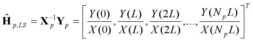
여기서, Xp는 전송된 파일럿 벡터, Yp는 수신된 파일럿 벡터, L은 파일럿 부반송파 간격, Np는 전체 파일럿 부반송파 개수를 나타낸다.Here, X p is a transmitted pilot vector, Y p is a received pilot vector, L is a pilot subcarrier spacing, and N p is a total number of pilot subcarriers.
[수학식 1]과 같이 LS 추정기로 추정된 채널 추정치를 사용하여 다음 [수학식 2]와 같이 데이터 부반송파의 채널이 추정된다.Using the channel estimate estimated by the LS estimator as shown in [Equation 1], the channel of the data subcarrier is estimated as shown in [Equation 2].

이와 같은 LS 추정기는 구조가 간단하지만, 채널 추정에 높은 성능을 나타내지는 못한다. 이를 해결하기 위하여 LS 추정기보다 구조는 복잡하지만 높은 성능을 나타내는 LMMSE 추정기가 대두되었다. Such an LS estimator is simple in structure but does not exhibit high performance in channel estimation. To solve this problem, the LMMSE estimator, which is more complicated in structure than the LS estimator but shows high performance, has emerged.
LMMSE 추정기는 다음 [수학식 3]과 같이 채널을 추정한다.The LMMSE estimator estimates a channel as shown in

여기서 ![]()
![]()
![]()
![]()
![]()
![]()
![]()
![]()
그러므로 N개의 부반송파에 대한 파일럿이 ![]()
![]()
![]()
![]()
![]()
![]()
![]()
![]()
![]()
![]()
![]()
![]()
![]()
![]()
![]()
![]()
![]()
![]()
이 외에 Ove Edfors 등은 1998년 7월 IEEE Trans. On Communications에 "OFDM Channel Estimation by Singular Valud Decomposition"을 발표하였으며, 여기서 보간 행렬을 미리 계산하여 LUT(Look Up Table)에 저장할 수 있는 방법을 제안하였다. 이때, 도플러 쉬프트는 무시할만하며 채널의 지연 확산 값 안에서 각 다중경로의 지연시간 및 전력이 균일(uniform) 분포를 갖는 랜덤 성질을 갖는다고 가정한다. Ove Edfors 등이 제안한 방법에서 채널은 다음 [수학식 4] 및 [수학식 5]와 같이 추정된다.In addition, Ove Edfors et al. Published in July 1998 IEEE Trans. He presented "OFDM Channel Estimation by Singular Valud Decomposition" to On Communications, and proposed a method to pre-calculate the interpolation matrix and store it in a look up table (LUT). In this case, the Doppler shift is negligible and it is assumed that the delay time and the power of each multipath have a random property with a uniform distribution in the delay spread value of the channel. In the method proposed by Ove Edfors et al., The channel is estimated by the following Equations 4 and 5.
![]()
![]()

여기서, rm,n은 m번째 부반송파와 n번째 부반송파 채널의 상관 값을, Lmax는 최대 지연 확산 값을, N은 FFT 포인트를 나타낸다.Here, r m, n denotes a correlation value between the m th subcarrier and the n th subcarrier channel, L max denotes a maximum delay spread value, and N denotes an FFT point.
그러나, LMMSE 추정기를 이용하여 채널을 추정하거나 상기 Ove Defors가 제안한 방식으로 채널을 추정할 때, 보간(interpolation) 행렬을 매번 계산하여야 하기 때문에, 계산량이 많아지고 그에 따라 하드웨어의 구현이 복잡해진다. 이를 해결하기 위해 대두된 추정 방식이 위너 FIR 필터링 추정 방식이다.However, when estimating the channel using the LMMSE estimator or estimating the channel in the manner suggested by the Ove Defors, the interpolation matrix has to be calculated each time, which increases the computational complexity and the complexity of the hardware implementation. In order to solve this problem, a rising estimation method is a Wiener FIR filtering estimation method.
위너 FIR 필터링 추정 방식에 의한 위너 FIR 필터링 추정기는 Ntap을 갖는 FIR 필터로 구현되는 위너 보간 필터를 포함한다. Np개의 모든 파일럿을 사용하는 LMMSE 기법에 비해 위너 FIR 필터링 기법은 Ntap개의 파일럿만을 사용하기 때문에, 계산량이 간단하면서도 높은 성능을 얻을 수 있다.The Wiener FIR filtering estimator according to the Wiener FIR filtering estimation scheme includes a Wiener interpolation filter implemented as an FIR filter having N taps . Compared to the LMMSE technique using all N p pilots, the Wiener FIR filtering technique uses only N tap pilots, so that a simple calculation and high performance can be obtained.
위너 FIR 필터링 기법에서의 채널은 Ntap개의 파일럿을 포함하는 윈도우를 전 체 밴드에 슬라이딩(Sliding) 시킴으로써 추정되며, 높은 성능을 얻기 위해 각 슬라이딩 윈도우의 중간 부분만을 추정한다. 위너 FIR 필터링 기법에서 채널의 추정 위치에 대해서 도 2를 참조로 설명하기로 한다.The channel in the Winner FIR filtering technique is estimated by sliding a window containing N tap pilots over the entire band, and only the middle portion of each sliding window is estimated to obtain high performance. An estimated position of a channel in the Wiener FIR filtering technique will be described with reference to FIG. 2.
도 2는 일반적인 OFDM 심볼에서 4개의 파일럿을 포함하는 윈도우를 사용할 때 파일럿과 채널 추정이 이루어지는 위치를 나타낸 예시도이다. 2 is an exemplary diagram showing a position where pilot and channel estimation are performed when using a window including four pilots in a general OFDM symbol.
도 2에 도시된 바와 같이, 위너 FIR 필터링 추정기의 n번째 부반송파에 대한 채널 추정은 다음 [수학식 6]과 같다.As shown in FIG. 2, the channel estimation for the nth subcarrier of the Wiener FIR filtering estimator is expressed by Equation 6 below.
![]()
![]()
여기서, ![]()
![]()
[수학식 7][Equation 7]

여기서, ![]()
![]()
![]()
![]()
![]()
![]()
![]()
![]()
![]()
![]()
![]()
![]()
이와 같이, LMMSE 추정기와 위너 FIR 필터링 추정기는 LS 추정기에 비해 상당히 정확한 채널 추정값을 제공하지만, [수학식 4]와 [수학식 5]를 채널의 변화에 대해 각각 계산할 경우 복잡도가 매우 높은 역행렬 연산을 필요로 한다.As such, the LMMSE estimator and Wiener FIR filtering estimator provide significantly more accurate channel estimates than the LS estimator. in need.
다음은, 일반적인 직교 주파수 분할 다중 이동통신 시스템에서 평균 제곱 에러에 대하여 도 3을 참고하여 설명하기로 한다. 여기서는 FFT 포인트가 1024이고, 10MHz의 심볼율을 갖는 직교 주파수 분할 다중 이동통신 시스템을 예로 하여 설명하기로 한다. Next, a mean square error in a general orthogonal frequency division multiplexing mobile communication system will be described with reference to FIG. 3. Here, an orthogonal frequency division multiplexing mobile communication system having an FFT point of 1024 and a symbol rate of 10 MHz will be described as an example.
도 3은 일반적인 다중경로 페이딩 채널의 RMS 지역확산 값에 따른 평균 제곱 에러를 나타낸 예시도이다.3 is an exemplary diagram illustrating an average squared error according to an RMS local spread value of a general multipath fading channel.
도 3에 도시된 바와 같이, 채널 추정기로는 파일럿 간격을 8로 하며 4개의 파일럿을 포함하는 윈도우(Ntap = 4)를 갖는 위너 FIR 필터링 추정기를 예로 하고, 각 그래프는 최대 지연 확산 값(Lmax)을 2.1us, 6.1us 및 9us로 각각 고정한 상태에서 신호대 잡음비(SNR)가 20dB일 때의 상태를 나타낸다. 채널의 RMS 지연 확산 값에 따라 최대 지연 확산 값에 따른 필터 계수를 변경해 주어야 하며, 이러한 경향은 그리 급격하지 않음으로 추정 단계를 간략화 하여도 크게 성능에 지장을 주지 않을 것으로 예측할 수 있다. As shown in FIG. 3, the channel estimator is an example of a Wiener FIR filtering estimator having a pilot interval of 8 and a window including four pilots (N tap = 4), and each graph shows a maximum delay spread value (L). max ) is fixed at 2.1us, 6.1us and 9us, respectively, and shows the state when the signal-to-noise ratio (SNR) is 20dB. It is necessary to change the filter coefficient according to the maximum delay spread value according to the RMS delay spread value of the channel. This trend is not so rapid, and it can be predicted that even if the estimation step is simplified, performance will not be greatly affected.
이와 같은 실시 예를 바탕으로, 본 발명의 실시예에서는 직교 주파수 분할 다중 이동통시 시스템에 적용되는 주위 환경 및 셀 반경 등을 고려하여, 후보가 되 는 최대 지연 확산 값을 3 단계로 나누어 필터 계수를 미리 계산하는 방식을 제안한다. 이를 위해, 먼저 채널 추정 장치의 구조에 대하여 도 4를 참조로 설명하기로 한다.Based on such an embodiment, the embodiment of the present invention considers the surrounding environment, cell radius, and the like applied to an orthogonal frequency division multiple mobile communication system, and divides the maximum delay spread value as a candidate into three stages. We suggest a precomputation method. To this end, first, the structure of the channel estimating apparatus will be described with reference to FIG. 4.
도 4는 본 발명의 실시예에 따른 채널 추정 장치의 구조도이다.4 is a structural diagram of a channel estimating apparatus according to an embodiment of the present invention.
도 4에 도시된 바와 같이, 채널 추정 장치는 송신단과 수신단이 다중 경로 채널을 통해 연결되어 있으며, 송신단은 신호 매핑부(100), 제1 직병렬 변환부(110), 파일럿 삽입부(120), IFFT 변환부(130), CP(Cyclic Prefix) 삽입부(140) 및 제1 병직렬 변환부(150)를 포함한다. 수신단은 제2 직병렬 변환부(170), CP 제거부(180), FFT 변환부(190), 신호 정정부(210), 채널 추정부(200), 제2 병직렬 변환부(220) 및 신호 디매핑부(230)를 포함한다.As shown in FIG. 4, in the channel estimating apparatus, a transmitter and a receiver are connected through a multipath channel, and the transmitter is a
각각의 구성 요소에 대해 좀 더 상세히 살펴보면, 먼저 송신단은 입력되는 데이터 신호를 복소 전송 심벌의 형태로 매핑하기 위한 신호 매핑부(100), 매핑된 신호를 각각의 부반송파 채널별로 할당하는 제1 직병렬 변환부(110), 부반송파 채널들 중에서 일정 부분의 부반송파 채널들에 채널 추정을 위하여 수신단에 미리 알려진 위치에 파일럿 신호를 채우는 파일럿 삽입부(120)를 포함한다. 이 외에도 송신단은 파일럿 신호를 포함하는 주파수 영역의 OFDM 신호들을 시간 영역의 OFDM 신호로 변환하는 IFFT 변환부(130), 시간 영역의 OFDM 신호로 변환된 전송 신호에 CP를 삽입하는 CP 삽입부(140) 및 CP가 삽입된 전송 신호를 시간에 따라 순차적으로 전송하기 위한 제1 병직렬 변환부(150)도 포함한다.Looking at each component in more detail, first, the transmitting end is a
수신단은 송신단으로부터 전송된 신호가 다중 경로 채널(160)을 통과하여 시 간에 따라 순차적으로 들어오는 신호들 중 OFDM 신호의 길이에 해당하는 블록을 선택하여 병렬로 정렬하는 제2 직병렬 변환부(170), 병렬로 정렬되는 시간영역의 OFDM 신호에서 송신단의 CP 삽입부(140)를 통해 삽입된 CP를 제거하는 CP 제거부(180), 시간영역의 OFDM 신호를 주파수 영역의 OFDM 신호로 변환하는 FFT 변환부(190)를 포함한다. 또한, 수신단은 주파수 영역에서 파일럿 신호를 이용하여 채널 계수 값을 추정하는 채널 추정부(200), 채널 추정부(200)에서 추정된 채널 계수 값을 이용하여 비이상적인 왜곡을 보상하는 신호 정정부(210), 왜곡이 보상된 주파수 영역의 신호를 전송 손서의 역순으로 정렬시키는 제2 병직렬 변환부(220) 및 주파수 영역의 신호를 디매핑하여 출력 데이터를 생성하는 신호 디매핑부(230)도 포함한다.The receiving end selects a block corresponding to the length of the OFDM signal among the signals sequentially transmitted over time through the
본 발명의 실시예에 따른 채널 추정 장치의 신호 매핑부(100)는 송신단으로 입력되는 이진 데이터 신호를 통상의 QAM(Quadrature Amplitude Modulation) 방식으로 매핑한다. 이때 QAM 방식은 QPSK(Quaternary Phase Shift Keying), 16-QAM 또는 64-QAM 변조 방식 중 어느 것을 사용해도 무방하다.The
신호 매핑부(100)에서 상기 매핑 방식 중 어느 하나로 매핑된 신호는 제1 직병렬 변환부(110)에서 병렬로 변환된 다음, 파일럿 삽입부(120)에서 상기 도 1과 같은 방식으로 각 OFDM 심볼에 일정 간격마다 파일럿이 삽입된다. 여기서 삽입되는 파일럿의 간격은 직교 주파수 분할 다중 이동통신 시스템이 적용되는 채널 환경에 따라 조정된다.The signal mapped by any one of the mapping schemes in the
파일럿을 포함한 각 OFDM 심볼 데이터는 IFFT 변환부(130)를 통해 역 푸리에 변환되고, 제1 병직렬 변환부(150)에서는 신호가 전송되기 위해 직렬 형태의 신호로 변환된 후 출력된다. 출력된 신호는 다중경로 페이딩 채널(160)을 거쳐 수신단으로 전송된다.Each OFDM symbol data including a pilot is inverse Fourier transformed through the
위에 기술된 바와 같은 구조로 이루어지는 송신단에서 전송된 신호는 다중경로 페이딩 채널(160)을 통해 왜곡이 발생되고, 수신단으로 수신된다.The signal transmitted from the transmitter having the structure as described above is distorted through the
수신 신호는 수신단의 제2 직병렬 변환부(170)에서 다시 병렬 신호로 변환되고, CP 제거부(180)를 통해 CP가 제거되어 FFT 변환부(190)로 입력된다. FFT 변환부(190)를 통해 푸리에 변환된 신호는 신호 정정부(210)로 입력되고, 신호 정정부(210)에서는 채널 추정부(200)에서 추정된 채널 계수값을 이용하여 다중경로 페이딩 채널(160)에서 인접 채널 간섭이나 다중 경로 페이딩 등에 의해 발생된 비 이상적인 왜곡을 보상한다. The received signal is converted into a parallel signal again by the second serial-to-
여기서, 채널 추정부(200)는 위너 FIR 필터링 추정 기법을 바탕으로 하여 상기 [수학식 7]로 표현되는 필터 계수를 계산할 때, 3단계의 지연 확산 값(예를 들어, 낮음, 중간 및 높음)에 대해 미리 계산한 값을 필터 계수에 적용하여 메모리에 미리 저장하고, 이동체의 이동에 따라 변하는 채널의 지연 확산 값을 추정한다. 이때, 3단계의 추정된 지연 확산 값에 따라 저장된 필터 계수를 위너 FIR 필터의 계수로 적용하여, 채널 추정에 이용한다.Here, when the
이와 같이 신호 정정부(210)를 통과한 신호는 다시 제2 병직렬 변환부(220)에서 직렬 형태의 신호로 변환되고, 신호 디매핑부(230)에서 원래 전송된 이진 데이터 형태의 신호로 출력된다.As such, the signal passing through the
다음은, 본 발명의 실시예에 따른 채널 추정부의 상세한 구조에 대하여 도 5를 참조하여 상세히 설명하기로 한다.Next, a detailed structure of the channel estimator according to the embodiment of the present invention will be described in detail with reference to FIG. 5.
도 5는 본 발명의 실시예에 따른 채널 추정부의 상세 블록을 나타낸 구조도이다.5 is a structural diagram illustrating a detailed block of a channel estimator according to an embodiment of the present invention.
도 5에 도시된 바와 같이, 본 발명의 실시예에 따른 채널 추정부(200)는 파일럿 추출 모듈(201), 채널 추정 모듈(202), 필터 모듈(203), 지연 확산 추정 모듈(204), 필터 계수 선택 모듈(205) 및 필터 계수 저장 모듈(206)을 포함한다.As shown in FIG. 5, the
파일럿 추출 모듈(201)은 FFT 변환부(190)를 통해 푸리에 변환된 신호를 입력받아 파일럿 신호만을 추출하여 출력한다.The
채널 추정 모듈(202)은 파일럿 추출 모듈(201)에서 출력된 파일럿 신호를 입력받아, 파일럿 신호에 대한 채널 추정값의 열(![]()
![]()
![]()
![]()
필터 모듈(203)은 채널 추정 모듈(202)에서 출력된 윈도우 내의 파일럿 신호 열들로 나뉜 채널 추정값의 열 값들을 입력받아 다수의 필터 계수들을 토대로 채널 추정 값을 추출한다. 여기서 다수의 필터 계수들은 하기에서 설명할 필터 계수 선택 모듈(205)로부터 입력받는다. 이때, 필터 모듈(203)에서 출력되는 채널 추정 값 은 전체 OFDM 심볼에 대한 채널 추정 값이 된다.The
지연 확산 추정 모듈(204)은 채널 추정 모듈(202)로부터 출력된 채널 추정값의 열 값들을 입력받아 지연 확산 값을 추정한다. 추정된 지연 확산 값은 신호 성분인 채널 값과 노이즈 성분인 백색 가우시안 노이즈(White Gaussian Noise)의 합의 형태로 모델링된다. 상기에서 설명한 바와 같이, 본 발명의 실시예에서는 3 단계(예를 들어, 낮음, 중간, 높음)의 값만을 추정하면 되기 때문에, 지연 확산 추정 모듈(204)은 간단한 알고리즘을 사용하여 구현될 수 있다.The delay spread
필터 계수 선택 모듈(205)은 상기 필터 모듈(203)로 입력되는 다수의 필터 계수들을 출력하는 기능을 수행한다. 즉, 지연 확산 추정 모듈(204)에서 추정된 지연 확산 값에 따라 필터 계수 1 내지 3 중 어느 하나를 선택하여 필터 모듈(203)로 출력한다. 본 발명의 실시예에서는 필터 계수를 3개로 하여 설명하고 있으나, 반드시 이와 같이 한정되는 것은 아니다. 또한, 필터 계수는 셀 반경에 따라 신호의 지연 정도가 변경되고 그에 따라 지연 계수도 변경되기 때문에, 지연 확산의 3 단계는 시스템의 설계자에 의해 동적으로 설정된다.The filter
필터 계수 저장 모듈(206)은 미리 계산되어 있는 필터 계수들이 저장되어 있으며, 필터 계수의 개수에 따라 필터 계수 저장 모듈의 개수도 달라진다. 여기서 필터 계수들은 상기 [수학식 4], [수학식 5] 및 [수학식 7]을 통해 미리 계산된다.The filter
다음은 상기에서 설명한 추정 장치를 이용하여 채널을 추정하는 방법에 대하여 도 6을 참조로 설명하기로 한다.Next, a method of estimating a channel using the above-described estimating apparatus will be described with reference to FIG. 6.
도 6은 본 발명의 실시예에 따른 채널 추정 방법의 흐름도이다.6 is a flowchart of a channel estimation method according to an embodiment of the present invention.
도 6에 도시된 바와 같이, FFT 변환부(190)를 통해 푸리에 변환이 수행된 신호를 수신한 파일럿 추출부(201)는 입력된 신호에서 파일럿 신호를 추출(S100)한다. 그 후, 추출된 파일럿 신호를 수신한 채널 추정 모듈(202)은 채널 추정을 통해 파일럿 신호에 대한 채널 추정값의 열 값을 출력(S110)한다. 여기서 채널 추정 모듈(202)은 LS 채널 추정 방식에 의해 채널 추정값의 열 값을 출력한다.As illustrated in FIG. 6, the
출력된 채널 추정값의 열 값은 필터 모듈(203)로 입력되고, 필터 모듈(203)은 입력된 채널 추정값의 열 값을 토대로 전체 OFDM 심볼에 대한 채널을 추정하여 신호 정정부(210)로 추정된 채널을 출력(S140)한다. 여기서 필터 모듈(203)이 OFDM 심볼에 대한 전체 채널을 추정하기 위해서는 필터 계수 선택 모듈(205)로부터 선택된 필터 계수를 입력받아 채널을 추정한다.The column value of the output channel estimate value is input to the
즉, 채널 추정 모듈(202)을 통해 추정된 채널 추정값의 열 값은 지연 확산 추정 모듈(204)로도 전달되고, 지연 확산 추정 모듈(204)은 이미 사용자가 시스템을 설계할 때 설정해 놓은 지연 확산 값 즉, 3단계의 임의의 값 중 채널 추정값의 열 값에 해당하는 지연 확산 값을 선택(S120)하여 필터 계수 선택 모듈(205)로 전송(S110)한다. 필터 계수 선택 모듈(205)은 지연 확산 추정 모듈(204)로부터 수신한 채널 지연 확산 추정값에 해당하는 필터 계수를 선택(S130)한 후 필터 계수 저장 모듈(206)로부터 수신하고, 수신된 필터 계수 값을 필터 모듈(203)로 전달한다.That is, the column value of the channel estimate estimated by the
상기에서와 같이 통해 필터 모듈(203)은 채널 추정값의 열 값 및 필터 계수 값을 토대로 전체 OFDM 심볼에 대한 채널을 추정하고, 추정된 결과를 신호 정정부(210)로 전달(S140)한다. 이와 같은 과정을 이용하면, 채널 추정부(200)는 필터 계수 값을 채널 추정시마다 계산하지 않고도 미리 저장되어 있는 필터 계수를 이용하기 때문에, 필터 계산에 필요한 계산량을 줄일 수 있으며, 채널의 지연 확산 값에 따라 필터의 계수를 바꿀 수 있기 때문에, 채널의 시간적 변화에 적응적으로 채널을 정확하게 추정할 수 있다.As described above, the
상기와 같이 추정된 채널을 통해 채널 추정 이후의 동작에 대하여 간략하게 설명하기 바람Please briefly describe the operation after channel estimation through the estimated channel as described above.
여기서, 전술한 본 발명의 실시예의 구성에 대응하는 기능을 실현하는 프로그램 또는 그 프로그램이 기록된 기록 매체 역시 본 발명의 범주에 포함되는 것이다.Here, a program for realizing a function corresponding to the configuration of the above-described embodiment of the present invention or a recording medium on which the program is recorded is also included in the scope of the present invention.
이상에서 본 발명의 실시예에 대하여 상세하게 설명하였지만 본 발명의 권리 범위는 이에 한정되는 것은 아니고 다음의 청구범위에서 정의하고 있는 본 발명의 기본 개념을 이용한 당업자의 여러 변형 및 개량 형태 또한 본 발명의 권리범위에 속하는 것이다.Although the embodiments of the present invention have been described in detail above, the scope of the present invention is not limited thereto, and various modifications and improvements of those skilled in the art using the basic concepts of the present invention defined in the following claims are also provided. It belongs to the scope of rights.
전술한 실시예에 따르면, 채널의 지연 확산 값에 따라 위너 FIR 필터의 계수를 바꾸어 줌으로써, 채널의 시간적 변화에 적응적으로 채널을 추정할 수 있다. According to the above-described embodiment, by changing the coefficient of the Wiener FIR filter according to the delay spread value of the channel, the channel can be estimated adaptively to the temporal change of the channel.
또한, 미리 계산된 필터 계수를 사용하기 때문에, 필터 계수를 계산하기 위한 계산량이 작아지므로 구현이 용이하다.In addition, since the pre-calculated filter coefficients are used, the calculation amount for calculating the filter coefficients is small, so the implementation is easy.
Claims (11)


Priority Applications (2)
| Application Number | Priority Date | Filing Date | Title |
|---|---|---|---|
| KR1020060124584A KR100764012B1 (en) | 2006-12-08 | 2006-12-08 | Apparatus and method for adaptive channel estimation corresponding to channel delay spread in communication system |
| US11/931,188 US8275053B2 (en) | 2006-12-08 | 2007-10-31 | Apparatus and method of estimating channel based on channel delay spread in mobile communication system |
Applications Claiming Priority (1)
| Application Number | Priority Date | Filing Date | Title |
|---|---|---|---|
| KR1020060124584A KR100764012B1 (en) | 2006-12-08 | 2006-12-08 | Apparatus and method for adaptive channel estimation corresponding to channel delay spread in communication system |
Publications (1)
| Publication Number | Publication Date |
|---|---|
| KR100764012B1 true KR100764012B1 (en) | 2007-10-08 |
Family
ID=39419283
Family Applications (1)
| Application Number | Title | Priority Date | Filing Date |
|---|---|---|---|
| KR1020060124584A KR100764012B1 (en) | 2006-12-08 | 2006-12-08 | Apparatus and method for adaptive channel estimation corresponding to channel delay spread in communication system |
Country Status (2)
| Country | Link |
|---|---|
| US (1) | US8275053B2 (en) |
| KR (1) | KR100764012B1 (en) |
Cited By (2)
| Publication number | Priority date | Publication date | Assignee | Title |
|---|---|---|---|---|
| KR101088916B1 (en) | 2010-01-28 | 2011-12-01 | 경희대학교 산학협력단 | Method for estimation downlink channel for OFDMA |
| CN111385230A (en) * | 2018-12-29 | 2020-07-07 | 中兴通讯股份有限公司 | Channel estimation method and system based on wiener self-adaptation |
Families Citing this family (15)
| Publication number | Priority date | Publication date | Assignee | Title |
|---|---|---|---|---|
| FR2938137B1 (en) * | 2008-10-31 | 2011-04-15 | St Microelectronics Sa | RECEIVER WITH CHANNEL ESTIMATION CIRCUIT. |
| TW201038024A (en) * | 2009-04-13 | 2010-10-16 | Univ Nat Chiao Tung | Channel estimation method of multi-carrier system |
| US8385818B2 (en) * | 2009-05-11 | 2013-02-26 | Qualcomm Incorporated | Delay control to improve frequency domain channel estimation in an echo cancellation repeater |
| US8995589B1 (en) * | 2010-11-17 | 2015-03-31 | James Qiu | Channel estimation in a pilot assisted OFDM system |
| US8995515B2 (en) * | 2010-12-29 | 2015-03-31 | Zte Wistron Telecom Ab | Dynamically adjusted OFDM channel estimation filtering in OFDM communications |
| US9258150B2 (en) * | 2010-12-29 | 2016-02-09 | Zte Wistron Telecom Ab | Channel estimation filtering |
| CN103503345A (en) * | 2011-05-10 | 2014-01-08 | Nec卡西欧移动通信株式会社 | Reception device, reception method, and computer program |
| US9794024B2 (en) | 2012-11-12 | 2017-10-17 | Apple Inc. | Adaptive channel state feedback estimation |
| WO2014172891A1 (en) | 2013-04-26 | 2014-10-30 | 华为技术有限公司 | Channel equalization method and device, and receiver |
| TWI504169B (en) * | 2013-05-31 | 2015-10-11 | Mstar Semiconductor Inc | Receiving apparatus for accelerating equalization convergence and method thereof |
| KR102655272B1 (en) | 2015-12-09 | 2024-04-08 | 코히어 테크놀로지스, 아이엔씨. | Pilot packing using complex orthogonal functions |
| DE102015122839B4 (en) * | 2015-12-24 | 2017-11-09 | Intel IP Corporation | A method of delay spreading classification of an orthogonal frequency division multiplexed signal and receiving device and associated telecommunication device |
| KR101706629B1 (en) * | 2016-01-25 | 2017-02-16 | 주식회사 이노와이어리스 | power calibration method for MIMO-OFDM transmitter |
| CN115694764A (en) | 2016-02-25 | 2023-02-03 | 凝聚技术公司 | Reference signal encapsulation for wireless communication |
| CN117135012B (en) * | 2023-10-26 | 2024-03-29 | 北京智芯微电子科技有限公司 | Delay spread estimation method and device |
Citations (1)
| Publication number | Priority date | Publication date | Assignee | Title |
|---|---|---|---|---|
| KR20030097093A (en) * | 2002-06-19 | 2003-12-31 | 주식회사 케이티 | A method and apparatus on coherent demodulation of OFDM signal for radio LAN systems |
Family Cites Families (7)
| Publication number | Priority date | Publication date | Assignee | Title |
|---|---|---|---|---|
| US6288674B1 (en) * | 1999-12-21 | 2001-09-11 | Texas Instruments Incorporated | Wireless communication system utilizing doppler diversity |
| US6650912B2 (en) * | 2000-09-18 | 2003-11-18 | Qualcomm, Incorporated | Selecting paging channel mode |
| KR20030014078A (en) | 2001-08-10 | 2003-02-15 | 최승국 | OFDM wireless transmission system using MMSE channel estimation |
| US7248559B2 (en) * | 2001-10-17 | 2007-07-24 | Nortel Networks Limited | Scattered pilot pattern and channel estimation method for MIMO-OFDM systems |
| US7039001B2 (en) | 2002-10-29 | 2006-05-02 | Qualcomm, Incorporated | Channel estimation for OFDM communication systems |
| KR100602518B1 (en) | 2004-06-30 | 2006-07-19 | 전자부품연구원 | Method and apparatus for channel estimation for ofdm based communication systems |
| US7630465B2 (en) * | 2004-11-23 | 2009-12-08 | Harris Corporation | Wireless communications device providing time and frequency-domain channel estimates interpolation and related methods |
-
2006
- 2006-12-08 KR KR1020060124584A patent/KR100764012B1/en active IP Right Grant
-
2007
- 2007-10-31 US US11/931,188 patent/US8275053B2/en active Active
Patent Citations (1)
| Publication number | Priority date | Publication date | Assignee | Title |
|---|---|---|---|---|
| KR20030097093A (en) * | 2002-06-19 | 2003-12-31 | 주식회사 케이티 | A method and apparatus on coherent demodulation of OFDM signal for radio LAN systems |
Cited By (3)
| Publication number | Priority date | Publication date | Assignee | Title |
|---|---|---|---|---|
| KR101088916B1 (en) | 2010-01-28 | 2011-12-01 | 경희대학교 산학협력단 | Method for estimation downlink channel for OFDMA |
| CN111385230A (en) * | 2018-12-29 | 2020-07-07 | 中兴通讯股份有限公司 | Channel estimation method and system based on wiener self-adaptation |
| CN111385230B (en) * | 2018-12-29 | 2023-03-14 | 中兴通讯股份有限公司 | Channel estimation method and system based on wiener self-adaptation |
Also Published As
| Publication number | Publication date |
|---|---|
| US20080137788A1 (en) | 2008-06-12 |
| US8275053B2 (en) | 2012-09-25 |
Similar Documents
| Publication | Publication Date | Title |
|---|---|---|
| KR100764012B1 (en) | Apparatus and method for adaptive channel estimation corresponding to channel delay spread in communication system | |
| KR100594084B1 (en) | Channel estimation method and channel estimator in ofdm/ofdma receiver | |
| KR101212471B1 (en) | Delay restricted channel estimation for multi-carrier systems | |
| EP2011293B1 (en) | Frequency domain channel estimation in a single carrier frequency division multiple access system | |
| CN109756434B (en) | System and method for OFDM-offset QAM | |
| KR101291683B1 (en) | Method of equalization for TDS-OFDM receiver and apparatus thereof | |
| US20090180558A1 (en) | OFDM Channel Estimation | |
| US7945005B2 (en) | Method and module for estimating transmission chanels of a multi-antenna multi-carrier system | |
| KR101241824B1 (en) | A receiver of communication system for orthogonal frequency division multiplexing and Method for mitigate a phase noise in thereof | |
| US20100046599A1 (en) | Apparatus and method for acquiring initial coefficient of decision feedback equalizer using fast fourier transform | |
| Zaier et al. | Channel estimation study for block-pilot insertion in OFDM systems under slowly time varying conditions | |
| US9385908B2 (en) | Communication apparatus and communication method | |
| WO2006006044A1 (en) | High doppler channel estimation for ofd multiple antenna systems | |
| JP2009534961A5 (en) | ||
| WO2009107146A1 (en) | Optimal training sequence and channel estimation method and system for superimposed training based ofdm systems | |
| Miyajima et al. | Second-order statistical approaches to channel shortening in multicarrier systems | |
| Zhou et al. | Channel Estimation Based on Linear Filtering Least Square in OFDM Systems. | |
| KR100656384B1 (en) | Channel estimation method using linear prediction in an ofdm communication system with virtual subcarriers, and device thereof | |
| CN108880777B (en) | Channel detection reference signal sending and receiving method suitable for UFMC waveform | |
| CN107968760B (en) | Receiving algorithm based on iterative channel estimation in filtering multi-tone modulation system | |
| JP2020088576A (en) | Transmission device and transmission method | |
| KR20060011758A (en) | A curve-fitting channel estimation method and ofdm system using the same method | |
| KR101160526B1 (en) | Method for channel estimation in ofdma system | |
| Khadagade et al. | Comparison of BER of OFDM system using QPSK and 16QAM over multipath rayleigh fading channel using pilot-based channel estimation | |
| JP2012105079A (en) | Radio communication system, transmitter and receiver |
Legal Events
| Date | Code | Title | Description |
|---|---|---|---|
| A201 | Request for examination | ||
| E701 | Decision to grant or registration of patent right | ||
| GRNT | Written decision to grant | ||
| FPAY | Annual fee payment |
Payment date: 20120830 Year of fee payment: 6 |
|
| FPAY | Annual fee payment |
Payment date: 20130829 Year of fee payment: 7 |
|
| FPAY | Annual fee payment |
Payment date: 20140828 Year of fee payment: 8 |
|
| FPAY | Annual fee payment |
Payment date: 20150828 Year of fee payment: 9 |
|
| FPAY | Annual fee payment |
Payment date: 20160830 Year of fee payment: 10 |
|
| FPAY | Annual fee payment |
Payment date: 20170830 Year of fee payment: 11 |
|
| FPAY | Annual fee payment |
Payment date: 20180830 Year of fee payment: 12 |
|
| FPAY | Annual fee payment |
Payment date: 20190829 Year of fee payment: 13 |