KR100752641B1 - Receiver and method for estimating common phase of Orthogonal Frequency Division Multiplexed signals using data subcarriers - Google Patents
Receiver and method for estimating common phase of Orthogonal Frequency Division Multiplexed signals using data subcarriers Download PDFInfo
- Publication number
- KR100752641B1 KR100752641B1 KR1020050006583A KR20050006583A KR100752641B1 KR 100752641 B1 KR100752641 B1 KR 100752641B1 KR 1020050006583 A KR1020050006583 A KR 1020050006583A KR 20050006583 A KR20050006583 A KR 20050006583A KR 100752641 B1 KR100752641 B1 KR 100752641B1
- Authority
- KR
- South Korea
- Prior art keywords
- signal
- subcarrier
- good
- channel
- subcarriers
- Prior art date
Links
- 238000000034 method Methods 0.000 title claims abstract description 32
- 239000013256 coordination polymer Substances 0.000 claims abstract 52
- 238000013507 mapping Methods 0.000 claims description 12
- 238000012545 processing Methods 0.000 claims description 5
- 230000002194 synthesizing effect Effects 0.000 claims description 3
- 238000013075 data extraction Methods 0.000 claims 2
- 238000010586 diagram Methods 0.000 description 6
- 230000005540 biological transmission Effects 0.000 description 5
- 239000000969 carrier Substances 0.000 description 3
- 238000012937 correction Methods 0.000 description 2
- 230000010363 phase shift Effects 0.000 description 2
- 238000004422 calculation algorithm Methods 0.000 description 1
- 238000004364 calculation method Methods 0.000 description 1
- 230000008859 change Effects 0.000 description 1
- 238000004891 communication Methods 0.000 description 1
- 238000001514 detection method Methods 0.000 description 1
- 239000000284 extract Substances 0.000 description 1
- 238000005562 fading Methods 0.000 description 1
- 230000006872 improvement Effects 0.000 description 1
- 238000005259 measurement Methods 0.000 description 1
- 238000012986 modification Methods 0.000 description 1
- 230000004048 modification Effects 0.000 description 1
- 230000008569 process Effects 0.000 description 1
- 230000004044 response Effects 0.000 description 1
- 230000011664 signaling Effects 0.000 description 1
- 229910052709 silver Inorganic materials 0.000 description 1
- 239000004332 silver Substances 0.000 description 1
- 238000004088 simulation Methods 0.000 description 1
- 230000005236 sound signal Effects 0.000 description 1
Images


Classifications
-
- B—PERFORMING OPERATIONS; TRANSPORTING
- B07—SEPARATING SOLIDS FROM SOLIDS; SORTING
- B07B—SEPARATING SOLIDS FROM SOLIDS BY SIEVING, SCREENING, SIFTING OR BY USING GAS CURRENTS; SEPARATING BY OTHER DRY METHODS APPLICABLE TO BULK MATERIAL, e.g. LOOSE ARTICLES FIT TO BE HANDLED LIKE BULK MATERIAL
- B07B13/00—Grading or sorting solid materials by dry methods, not otherwise provided for; Sorting articles otherwise than by indirectly controlled devices
- B07B13/14—Details or accessories
- B07B13/16—Feed or discharge arrangements
-
- H—ELECTRICITY
- H04—ELECTRIC COMMUNICATION TECHNIQUE
- H04L—TRANSMISSION OF DIGITAL INFORMATION, e.g. TELEGRAPHIC COMMUNICATION
- H04L27/00—Modulated-carrier systems
- H04L27/26—Systems using multi-frequency codes
- H04L27/2601—Multicarrier modulation systems
- H04L27/2647—Arrangements specific to the receiver only
- H04L27/2655—Synchronisation arrangements
- H04L27/2657—Carrier synchronisation
-
- H—ELECTRICITY
- H04—ELECTRIC COMMUNICATION TECHNIQUE
- H04L—TRANSMISSION OF DIGITAL INFORMATION, e.g. TELEGRAPHIC COMMUNICATION
- H04L27/00—Modulated-carrier systems
- H04L27/26—Systems using multi-frequency codes
- H04L27/2601—Multicarrier modulation systems
- H04L27/2647—Arrangements specific to the receiver only
- H04L27/2655—Synchronisation arrangements
- H04L27/2668—Details of algorithms
- H04L27/2673—Details of algorithms characterised by synchronisation parameters
- H04L27/2676—Blind, i.e. without using known symbols
- H04L27/2679—Decision-aided
-
- H—ELECTRICITY
- H04—ELECTRIC COMMUNICATION TECHNIQUE
- H04L—TRANSMISSION OF DIGITAL INFORMATION, e.g. TELEGRAPHIC COMMUNICATION
- H04L25/00—Baseband systems
- H04L25/02—Details ; arrangements for supplying electrical power along data transmission lines
- H04L25/03—Shaping networks in transmitter or receiver, e.g. adaptive shaping networks
- H04L25/03006—Arrangements for removing intersymbol interference
- H04L2025/0335—Arrangements for removing intersymbol interference characterised by the type of transmission
- H04L2025/03375—Passband transmission
- H04L2025/03414—Multicarrier
-
- H—ELECTRICITY
- H04—ELECTRIC COMMUNICATION TECHNIQUE
- H04L—TRANSMISSION OF DIGITAL INFORMATION, e.g. TELEGRAPHIC COMMUNICATION
- H04L25/00—Baseband systems
- H04L25/02—Details ; arrangements for supplying electrical power along data transmission lines
- H04L25/0202—Channel estimation
- H04L25/022—Channel estimation of frequency response
Abstract
데이터 서브캐리어를 이용하여 공통 위상을 추정하는 OFDM 신호 수신기 및 방법이 개시된다. 상기 수신기에서는 채널 평가부가 FFT 처리된 신호로부터 채널을 추정하여 양호 서브캐리어 인덱스에 관한 정보를 CSI로서 생성하고, CP 추정부가 등화기에서 출력되는 왜곡 보상된 신호로부터 상기 CSI에 따라 양호 파일럿 및 데이터 서브캐리어를 추정하여 상기 추정된 서브캐리어들로부터 제1 CP 및 제2 CP를 계산하고, 상기 계산된 CP들을 합성하여 최종 CP를 생성한다. 이에 따라, CP 보상부는 상기 최종 CP만큼 상기 왜곡 보상된 신호의 위상을 보상하여 출력한다. An OFDM signal receiver and method are disclosed for estimating common phase using data subcarriers. In the receiver, the channel evaluator estimates a channel from the FFT processed signal to generate information on the good subcarrier index as the CSI, and the CP estimator outputs the good pilot and data subs according to the CSI from the distortion compensated signal output from the equalizer. A carrier is estimated to calculate a first CP and a second CP from the estimated subcarriers, and the calculated CPs are synthesized to generate a final CP. Accordingly, the CP compensator compensates and outputs the phase of the distortion compensated signal by the final CP.
Description
본 발명의 상세한 설명에서 인용되는 도면을 보다 충분히 이해하기 위하여 각 도면의 간단한 설명이 제공된다.BRIEF DESCRIPTION OF THE DRAWINGS In order to better understand the drawings cited in the detailed description of the invention, a brief description of each drawing is provided.
도 1은 일반적인 OFDM 신호 수신기의 블록도이다.1 is a block diagram of a typical OFDM signal receiver.
도 2는 본 발명의 일시예에 따른 OFDM 신호 수신기의 블록도이다.2 is a block diagram of an OFDM signal receiver according to an embodiment of the present invention.
도 3은 도 2의 서브캐리어 추정부 및 CP 결정부의 구체적인 블록도이다.3 is a detailed block diagram of the subcarrier estimator and CP determiner of FIG. 2.
도 4는 도 2의 OFDM 신호 수신기 동작 설명을 위한 흐름도이다.4 is a flowchart for describing an operation of an OFDM signal receiver of FIG. 2.
도 5는 64-QAM 포맷에서의 I-Q 콘스텔레이션 그래프이다.5 is an I-Q constellation graph in 64-QAM format.
도 6은 256-QAM 포맷에서의 I-Q 콘스텔레이션 그래프이다.6 is an I-Q constellation graph in 256-QAM format.
도 7은 본 발명의 일시예에 따른 OFDM 신호 수신기의 성능을 설명하기 위한 SNR에 대한 BER를 나타내는 그래프이다.7 is a graph illustrating BER versus SNR for explaining the performance of an OFDM signal receiver according to an embodiment of the present invention.
본 발명은 OFDM(Orthogonal Frequency Division Multiplexer) 신호 수신기에 관한 것으로, 특히 수신된 OFDM 신호에서 파일럿(pilot) 서브캐리어 뿐만 아니라 데이터 서브캐리어를 이용하여 CP(공통 위상: common phase)을 추정하는 장치 및 방법에 관한 것이다.The present invention relates to an orthogonal frequency division multiplexer (OFDM) signal receiver, and more particularly, to an apparatus and method for estimating a common phase (CP) using a data subcarrier as well as a pilot subcarrier in a received OFDM signal. It is about.
OFDM 신호에 기반한 다중 캐리어는 DVB-T(Terrestrial Digital Video Broadcasting) 시스템 등에 이용된다. OFDM 신호의 한 프레임은 68 심볼로 구성되어 있고, 각 심볼에는 2K 또는 8K 모드 각각에 따라 1705 액티브 캐리어 및 6817 액티브 캐리어가 포함되어 있다. 각 심볼의 액티브 캐리어는 데이터 서브캐리어와 파일럿 서브캐리어를 포함한다. 데이터 서브캐리어는 송수신될 실질적인 오디오/비디오 정보가 디지털화된 신호이고, 파일럿 서브캐리어는 동기화, 모드 검출, 채널 추정 등에 사용될 디지털 신호로서, 데이터 서브캐리어의 사이에 삽입되고, 이러한 파일럿 서브캐리어들의 위치는 미리 정해져 있다. Multiple carriers based on OFDM signals are used in a DVB-T (Terrestrial Digital Video Broadcasting) system. One frame of the OFDM signal consists of 68 symbols, and each symbol includes 1705 active carriers and 6817 active carriers according to 2K or 8K modes, respectively. The active carrier of each symbol includes a data subcarrier and a pilot subcarrier. The data subcarrier is a signal in which substantial audio / video information to be transmitted and received is digitized, and the pilot subcarrier is a digital signal to be used for synchronization, mode detection, channel estimation, and the like, and is inserted between data subcarriers, and the positions of the pilot subcarriers It is predetermined.
도 1은 일반적인 OFDM 신호 수신기(100)의 블록도이다. 도 1을 참조하면, 상기 수신기(100)는 RF 모듈(module)(110), 복조기(120), 주파수 동기화부(frequency synchronization unit)(130), FFT부(Fast Fourier Transform Unit)(140), 등화기(equalizer)(150), CP 추정/보상부(Commom Phase estimation and correction unit)(160), 및 디매퍼(demapper)(170)를 구비한다. 1 is a block diagram of a typical
상기 복조기(120)는 RF 모듈(110)로부터 입력되는 디지털 OFDM 수신 신호를 QPSK, BPSK, QAM 등의 시그널링 포맷으로 복조하여 복소 신호인 I(In-phase) 신호 및 Q(Quadrature-phase) 신호를 생성한다. 상기 디지털 OFDM 수신 신호는 상기 복조기(110)에서 저주파수로 다운-컨버팅(down-converted)되고 복조된다. 상기 복조 된 신호는 상기 주파수 동기화부(130)를 통과하면서 FO(frequency offset)이 보상된다. 이때, 상기 주파수 동기화부(130)는 상기 복조된 신호로부터 FO를 추정하는데, 잡음과 채널의 왜곡으로 인하여 추정 오류가 발생하는 경우에, 상기 주파수 동기화부(130)에서 보상된 신호에는 잔류 FO가 포함될 수 있다. 상기 주파수 동기화부(130)에서 보상된 신호는 상기 FFT부(140)를 통과한 후, 상기 등화기(150)에서 채널의 왜곡이 보상되고, 상기 CP 보상부(160)에서 모든 서브캐리어에서 동일하게 발생한 CP 오류가 추정되고 보상된다. CP는 모든 서브캐리어에서 동일하게 발생된 본래 송신된 신호와의 위상차이며, 그 원인은 잔류 FO와 상기 RF 모듈(110) 내의 소정 발진기(oscillator) 출력의 위상 노이즈(phase noise)가 주원인으로 알려져 있다. The
이와 같은 종래 기술에서는, CP를 추정하기 위해 파일럿 서브캐리어를 사용하였다. 파일럿 서브캐리어는 OFDM 시스템에서 송수신기간에 약속한 값을 전송하는 데 사용되는 서브캐리어로서, 수신기가 FO 혹은 채널 왜곡 등을 추정하기 위한 목적으로 사용된다. In this prior art, pilot subcarriers have been used to estimate CP. A pilot subcarrier is a subcarrier used to transmit a promised value in a transmission / reception period in an OFDM system, and is used by a receiver to estimate FO or channel distortion.
일반적으로, CP는 모든 서브캐리어에 동일하게 발생된 위상 오류이므로, 파일럿 서브캐리어에 발생된 위상 회전(rotation)을 이용하여 추정될 수 있다. 잔류 FO로 인해 캐리어에 발생된 위상 회전량을 추정한 값 ![]()
![]()
[수학식 1][Equation 1]

상기 CP 추정/보상부(160)는 [수학식 1]의 연산을 위하여, 상기 등화기(150)에서 출력되는 왜곡 보상된(equalized) 신호에서 파일럿 서브캐리어들을 추출한다. 다음에, 상기 CP 추정/보상부(160)는 [수학식 1]과 같이, 추출된 파일럿 서브캐리어 Rk와 송신된 본래의 파일럿 서브캐리어 Sk의 공액복소수를 곱하여 곱한 결과들을 모두 합한 후 그 결과로부터 얻어지는 복소값에 대한 tan-1값을 추정 위상 회전량 ![]()
![]()
이와 같이, 파일럿의 송수신값 간의 위상 변화량을 이용하여 CP를 추정할 수 있으나, 잡음이나 채널의 왜곡이 존재할 경우에 파일럿을 이용한 CP 추정에 추정 오류가 발생할 수 있다는 문제점이 있다. CP 추정 정확도를 높이기 위하여 파일럿의 개수를 증가시킬 수 있지만, 그만큼 시스템의 총 전송율이 낮아지므로 통신 환경에 따라 파일럿의 개수를 적절히 정해야한다. 특히, IEEE802.11a과 같이 총 4개의 파일럿을 사용할 경우, CP 추정 정확도가 낮아 잡음과 채널의 왜곡에 민감해질 수 있으므로, 이를 개선할 필요가 있다.As described above, the CP can be estimated using the amount of phase change between the transmission and reception values of the pilot, but there is a problem that an estimation error may occur in the CP estimation using the pilot when noise or channel distortion exists. Although the number of pilots can be increased to increase the accuracy of CP estimation, the total transmission rate of the system is lowered accordingly, so the number of pilots should be appropriately determined according to the communication environment. In particular, when using a total of four pilots, such as IEEE802.11a, the CP estimation accuracy is low, so it may be sensitive to noise and distortion of the channel, it is necessary to improve this.
따라서, 본 발명이 이루고자 하는 기술적 과제는, 파일럿 서브캐리어를 이용할 뿐만 아니라, DD(decision directed) 추정 알고리즘에서 좀 더 신뢰성있게 결정된 데이터 서브캐리어를 이용하여 CP를 추정함으로써, 시스템 성능을 향상킬 수 있는 OFDM 신호 수신기를 제공하는 데 있다. Accordingly, the technical problem to be achieved by the present invention is not only to use a pilot subcarrier but also to estimate a CP using a data subcarrier determined more reliably in a decision directed (DD) estimation algorithm, thereby improving system performance. An OFDM signal receiver is provided.
본 발명이 이루고자 하는 다른 기술적 과제는, OFDM 신호 수신기에서 파일럿 서브캐리어 이외에 데이터 서브캐리어를 이용하여 CP를 추정하는 방법을 제공하는 데 있다.Another object of the present invention is to provide a method for estimating CP using data subcarriers in addition to pilot subcarriers in an OFDM signal receiver.
상기 기술적 과제를 달성하기 위한 본 발명에 따른 OFDM 신호 수신기는, 등화기, 채널 평가부, CP 추정부, 및 CP 보상부를 구비하는 것을 특징으로 한다. 상기 등화기는 입력 기저대역의 신호를 왜곡 보상한다. 상기 채널 평가부는 상기 기저대역의 신호로부터 채널을 추정하여 양호 서브캐리어 인덱스에 관한 정보를 CSI로서 생성한다. 상기 CP 추정부는 상기 왜곡 보상된 신호로부터 상기 CSI에 따라 양호 파일럿 및 데이터 서브캐리어를 추정하여 상기 추정된 서브캐리어들로부터 제1 CP 및 제2 CP를 계산하고, 상기 계산된 CP들을 합성하여 최종 CP를 생성한다. 상기 CP 보상부는 상기 최종 CP 만큼 상기 왜곡 보상된 신호의 위상을 보상하여 출력한다. An OFDM signal receiver according to the present invention for achieving the above technical problem is characterized by including an equalizer, a channel evaluator, a CP estimator, and a CP compensator. The equalizer distorts the input baseband signal. The channel evaluator estimates a channel from the baseband signal to generate information about a good subcarrier index as the CSI. The CP estimator estimates a good pilot and data subcarrier according to the CSI from the distortion compensated signal, calculates a first CP and a second CP from the estimated subcarriers, synthesizes the calculated CPs, and generates a final CP. Create The CP compensator compensates and outputs the phase of the distortion compensated signal by the final CP.
상기 OFDM 신호 수신기는 복조기, 주파수 동기화부, 및 FFT부를 더 구비하는 것을 특징으로 한다. 상기 복조기는 RF 모듈로부터의 디지털 OFDM 수신 신호를 일 정 포맷으로 복조하여 복소 신호를 생성한다. 상기 주파수 동기화부는 상기 복조된 신호의 주파수 옵셋을 보상한다. 상기 FFT부는 상기 주파수 보상된 신호를 FFT 처리하여 FFT 처리된 신호를 상기 입력 기저대역의 신호로서 생성한다. The OFDM signal receiver further includes a demodulator, a frequency synchronizer, and an FFT unit. The demodulator demodulates the digital OFDM received signal from the RF module in a predetermined format to generate a complex signal. The frequency synchronizer compensates for a frequency offset of the demodulated signal. The FFT unit performs FFT processing on the frequency compensated signal to generate an FFT processed signal as the input baseband signal.
상기 OFDM 신호 수신기는 상기 CP 보상된 신호를 일정 포맷에 따라 디매핑하는 디매퍼를 더 구비하는 것을 특징으로 한다. The OFDM signal receiver further includes a demapper for demapping the CP compensated signal according to a predetermined format.
상기 기술적 과제를 달성하기 위한 본 발명에 따른 OFDM 신호 수신 방법은, 입력 기저대역의 신호를 왜곡 보상하는 단계; 상기 기저대역의 신호로부터 채널을 추정하여 양호 서브캐리어 인덱스에 관한 정보를 CSI로서 생성하는 단계; 상기 왜곡 보상된 신호로부터 상기 CSI에 따라 양호 파일럿 및 데이터 서브캐리어를 추정하는 단계: 상기 추정된 서브캐리어들로부터 제1 CP 및 제2 CP를 계산하는 단계; 상기 계산된 CP들을 합성하여 최종 CP를 생성하는 단계; 및 상기 최종 CP 만큼 상기 왜곡 보상된 신호의 위상을 보상하는 단계를 구비하는 것을 특징으로 한다.According to an aspect of the present invention, there is provided a method for receiving an OFDM signal, comprising: distortion-compensating a signal of an input baseband; Estimating a channel from the baseband signal to generate information about a good subcarrier index as a CSI; Estimating a good pilot and data subcarrier according to the CSI from the distortion compensated signal: calculating a first CP and a second CP from the estimated subcarriers; Synthesizing the calculated CPs to generate a final CP; And compensating for the phase of the distortion compensated signal by the final CP.
본 발명과 본 발명의 동작상의 이점 및 본 발명의 실시에 의하여 달성되는 목적을 충분히 이해하기 위해서는 본 발명의 바람직한 실시예를 예시하는 첨부 도면 및 도면에 기재된 내용을 참조하여야 한다.DETAILED DESCRIPTION In order to fully understand the present invention, the operational advantages of the present invention, and the objects achieved by the practice of the present invention, reference should be made to the accompanying drawings which illustrate preferred embodiments of the present invention and the contents described in the drawings.
이하, 첨부한 도면을 참조하여 본 발명의 바람직한 실시예를 설명함으로써, 본 발명을 상세히 설명한다. 각 도면에 제시된 동일한 참조부호는 동일한 부재를 나타낸다.Hereinafter, exemplary embodiments of the present invention will be described in detail with reference to the accompanying drawings. Like reference numerals in the drawings denote like elements.
도 2는 본 발명의 일시예에 따른 OFDM 신호 수신기(200)의 블록도이다. 도 2를 참조하면, 상기 수신기(200)는 RF 모듈(Radio Frequency module)(210), 복조기 (demodulator)(220), 주파수 동기화부(frequency synchronization unit)(230), FFT부(Fast Fourier Transform unit)(240), 등화기(equalizer)(250), 채널 평가부(channel measurement unit)(270), CP 추정부(280), CP 보상부(260), 및 디매퍼(demapper)(290)를 구비한다. 2 is a block diagram of an
상기 복조기(220)는 RF 모듈(210)로부터 입력되는 디지털 OFDM 수신 신호를 QAM(Quadrature Amplitude Modulation) 포맷, BPSK(Binary Phase-Shift Keying) 포맷, 또는 QPSK(Quadrature Phase-Shift Keying) 포맷 등 그 다양한 포맷에 따라, 복조하여 복소 신호인 I(In-phase) 신호 및 Q(Quadrature-phase) 신호를 생성한다. 상기 RF 모듈(210)로부터 입력되는 상기 디지털 OFDM 수신 신호는 상기 복조기(220)에서 저주파수로 다운-컨버팅(down-converted)되고 복조된다. 상기 복조기(220)에는 모든 회로들에서 이용될 칩-레이트(chip-rate) 클럭 신호 및 심볼-레이트(symbol-rate) 클럭 신호를 포함하는 모든 필요한 동기 신호들을 재구성하는 동기 회로가 포함된다. 상기 복조기(220)에서 출력되는 상기 복조된 신호는 기저 대역에서 샘플링된 복소 신호(baseband sampled complex signal)이다. The
상기 주파수 동기화부(230)는 상기 복조된 신호의 주파수 옵셋을 보상한다. 상기 FFT부(240)는 상기 주파수 보상된 신호를 FFT 처리한다. FFT 처리에 대해서는 이 분야에서 통상의 지식을 가진 자에게 잘 알려져 있다. 상기 FFT 처리된 기저대역의 신호는 주파수 영역의 복소 신호(frequency domain complex signal)이다. 상기 등화기(250)는 상기 FFT 처리된 기저대역의 신호를 왜곡 보상(equalizing)한다. 상기 등화기(250)는 상기 채널 평가부(270)에 포함된 채널 추정부(271)에서 추정되 는 각 서브캐리어와 관련된 채널 계수 Hk를 이용하여 왜곡 보상할 수 있다.The
상기 수신기(200)는 파일럿 서브캐리어 이외에 데이터 서브캐리어를 이용하여 CP를 추정하기 위하여 제안되었다. The
이를 위하여, 상기 채널 평가부(270)는 상기 FFT 처리된 기저대역의 신호로부터 채널을 추정하여 양호 서브캐리어 인덱스에 관한 정보를 CSI(Channel State Information)로서 생성한다. 상기 CP 추정부(280)는 상기 왜곡 보상된(equalized) 신호로부터 상기 CSI에 따라 양호 파일럿 서브캐리어 Rk 및 양호 데이터 서브캐리어 Yk를 추정하여 상기 추정된 서브캐리어들로부터 제1 CP ![]()
![]()
![]()
![]()
![]()
![]()
![]()
![]()
이하, 도 4의 흐름도를 참조하여, 상기 채널 평가부(270) 및 상기 CP 추정부(280)의 동작을 좀더 자세히 설명한다. Hereinafter, operations of the
먼저, 상기 채널 평가부(270) 및 상기 등화기(250)는 상기 FFT 처리된 기저 대역의 신호를 수신한다(S41). 상기 등화기(250)가 상기 FFT 처리된 기저대역의 신호를 왜곡 보상하는 동안, 상기 채널 평가부(270)는 채널을 추정하여 CSI를 생성한다. 이에 따라, 상기 CP 추정부(280)는 상기 CSI에 따라 상기 왜곡 보상된(equalized) 신호로부터 최종 CP ![]()
![]()
도 2에서, 상기 채널 평가부(270)는 채널 추정부(271) 및 양호 서브캐리어 인덱스부(272)를 포함한다. 상기 채널 추정부(271)는 상기 FFT 처리된 신호로부터 채널을 추정하여 각 서브캐리어와 관련된 채널 계수 Hk를 생성한다. 상기 채널 계수 Hk는 각 서브캐리어의 파워(power)와 관련된 채널 주파수 응답(channel frequency response)의 크기 신호이다. 이에 따라, 상기 양호 서브캐리어 인덱스부(272)는 [수학식 2]와 같이, 상기 채널 계수들 Hk의 파워의 평균 ![]()
![]()
[수학식 2][Equation 2]
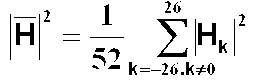
[수학식 2]에서 유효 서브캐리어 수는 52개인 것으로 가정되었다. 즉, 본 시스템에 사용되는 FFT 사이즈는 64이며, 이 중 52개에 유효 서브캐리어가 실리고, 52개 중 4개에 파일럿 서브캐리어 및 52개 중 48개에 데이터 서브캐리어가 실리는 것으로 가정하였다. In
상기 양호 서브캐리어 인덱스부(272)는 [수학식 3]과 같이, 상기 채널 추정부(271)에서 생성되는 상기 각 채널 계수 Hk의 파워가 상기 평균 ![]()
![]()
[수학식 3][Equation 3]

양호 서브캐리어에 대하여 인덱싱되면, 상기 CP 추정부(280)는 상기 채널 평가부(270)에서 생성된 상기 CSI에 따라 상기 왜곡 보상된(equalized) 신호로부터 최종 CP ![]()
![]()
도 2에서, 상기 CP 추정부(280)는 서브캐리어 추정부(281) 및 CP 결정부(282)를 포함한다. 상기 서브캐리어 추정부(281)는 양호 파일럿 서브캐리어 Rk 및 양호 데이터 서브캐리어 Yk를 추정한다. 상기 CP 결정부(282)는 상기 제1 CP ![]()
![]()
![]()
![]()
![]()
![]()
도 3은 상기 서브캐리어 추정부(281) 및 CP 결정부(282)의 구체적인 블록도가 도 3에 도시되어 있다. 도 3을 참조하면, 상기 서브캐리어 추정부(281)는 파일럿 추출부(282) 및 데이터 추출부(283)를 포함하고, 상기 CP 결정부(282)는 제1 CP 결정부(286), 제2 CP 결정부(287), 및 최종 결정부(288)를 포함한다.FIG. 3 is a detailed block diagram of the
상기 파일럿 추출부(282)는 상기 CSI에 따라 [수학식 3]과 같이, 상기 채널 평가부(270)에서 생성된 상기 채널 계수들 Hk의 파워 평균의 1/2보다 큰(양호 서브캐리어로 판단된) 파일럿 서브캐리어어를 상기 양호 파일럿 서브캐리어 Rk로서 출력한다(S44). 여기서, CP 추정의 정확도를 높이기 위하여, 채널 특성이 좋지 않은 파일럿을 제외시키기 위함이다.The
상기 데이터 추출부(283)는 상기 CSI에 따라 [수학식 4]와 같이, [수학식 3]에 따라 상기 채널 계수들의 파워 평균의 1/2 보다 큰(양호 서브캐리어로 판단된) 데이터 서브캐리어 중 실수 성분 Re(Yk)및 허수 성분 Im(Yk)이 모두 콘스텔레이션(constellation)에 따른 최대 매핑 레벨(mapping level)의 1/2이상인 데이터 서브캐리어를 양호 데이터 서브캐리어 Yk로서 출력한다(S46). 여기서도, CP 추정의 정확도를 높이기 위하여, 채널 특성이 좋지 않은 데이터를 제외시킨다. 64-QAM 및 256-QAM 변조 포맷에서 I-Q 콘스텔레이션 그래프는 도 5 및 도 6과 같으며, 여기서 최대 매핑 레벨의 1/2은, 64-QAM에서는 중심점으로부터 상/하/좌/우로 두 칸이고, 256-QAM에서는 중심점으로부터 상/하/좌/우로 4칸이다. The
[수학식 4][Equation 4]
![]()
![]()
또한, 상기 데이터 추출부(283)는 본 시스템에 사용되는 FFT 사이즈(예를 들어, 64) 내에 존재하는 상기 양호 데이터 서브캐리어 수(m)를 생성한다.In addition, the
한편, 상기 제1 CP 결정부(286)는 상기 파일럿 추출부(282)에서 추출된 상기 양호 파일럿 서브캐리어들 Rk을 이용하여, [수학식 1]과 같이, 추정 위상 회전량 ![]()
![]()
![]()
![]()
![]()
![]()
상기 제2 CP 결정부(287)는 제2 CP ![]()
![]()
![]()
![]()
![]()
![]()
[수학식 5][Equation 5]
![]()
![]()
이와 같이, 매핑 레벨 Gk이 결정되면, 상기 제2 CP 결정부(287)는 [수학식 6]과 같이, 상기 결정된 매핑 레벨들 Gk을 기준으로 상기 양호 데이터 서브캐리어들 Yk에 대한 위상 회전량을 상기 제2 CP ![]()
![]()
[수학식 6][Equation 6]

여기서, 상기 제2 CP 결정부(287)는 상기 계산된 제2 CP ![]()
![]()
![]()
![]()
![]()
![]()
![]()
![]()
이에 따라, 상기 최종 결정부(288)는 상기 제1 CP ![]()
![]()
![]()
![]()
![]()
![]()
![]()
![]()
![]()
![]()
![]()
![]()
[수학식 7][Equation 7]

상기 최종 결정부(288)는 상기 양호 데이터 서브캐리어 수(m)가 시스템에 사용된 파일럿 서브캐리어 수(예를 들어, 4)보다 작으면, 상기 제1 CP ![]()
![]()
![]()
![]()
![]()
![]()
도 7은 본 발명의 일시예에 따른 OFDM 신호 수신기(200)의 성능을 설명하기 위한 SNR(Signal-to-Noise power Ratio)에 대한 BER(Bit Error Ratio)를 나타내는 그래프이다. 본 시뮬레이션에서는 256-QAM 변조 포맷을 사용하였고, 실내 무선 환경에서 RMS(Root Mean Square) 딜레이 스프레드(delay spread)가 50ns인 다중 경로 페이딩(multipath fading) 채널의 성능을 나타낸다. 도 7에서, "Pef FS, Pef EQ, CP off", 즉, 이상적인 경우(완전한 주파수 옵셋 보상과 등화, 및 CP 추정 안 함)와 비교된 종래기술의 성능("Pef FS, Pef EQ, CP on"/"Est FS, Est EQ, CP on")과 본 발명의 성능("Pef FS, Pef EQ, CP(M) on"/"Est FS, Est EQ, CP(M) on")이 나타나있다. 완전한 주파수 옵셋 보상과 등화가 이루어지는 경우("Pef FS, Pef EQ")에는, CP 추정부(280)에 따라 동작하는 본원 발명("CP(M) on")은 종래기술("CP on")에 비하여 0.3dB의 SNR 개선을 획득할 수 있다. 또한, 주파수 옵셋 보상과 등화가 실제로 추정되는 경우("Est FS, Est EQ")에도, 본원 발명("CP(M) on")은 종래기술("CP on")에 비하여 0.3dB의 SNR 개선을 획득할 수 있다. 7 is a graph illustrating a bit error ratio (BER) with respect to a signal-to-noise power ratio (SNR) for explaining the performance of the
위에서 기술한 바와 같이, 본 발명의 일실시예에 따른 OFDM 신호 수신기(200)에서는, 채널 평가부(270)가 FFT 처리된 신호로부터 채널을 추정하여 양호 서브캐리어 인덱스에 관한 정보를 CSI로서 생성하고, CP 추정부(280)가 등화기(250)에서 출력되는 왜곡 보상된 신호로부터 상기 CSI에 따라 양호 파일럿(Rk) 및 데이터 서브캐리어(Yk)를 추정하여 상기 추정된 서브캐리어들로부터 제1 CP ![]()
![]()
![]()
![]()
![]()
![]()
![]()
![]()
이상에서와 같이 도면과 명세서에 최적 실시예가 개시되었다. 여기서 특정한 용어들이 사용되었으나, 이는 단지 본 발명을 설명하기 위한 목적에서 사용된 것이지 의미한정이나 특허청구범위에 기재된 본 발명의 범위를 제한하기 위하여 사용된 것은 아니다. 그러므로 본 기술분야의 통상의 지식을 가진 자라면 이로부터 다양한 변형 및 균등한 타실시예가 가능하다는 점을 이해할 것이다. 따라서 본 발명의 진정한 기술적 보호범위는 첨부된 특허청구범위의 기술적 사상에 의해 정해져야 할 것이다.As described above, optimal embodiments have been disclosed in the drawings and the specification. Although specific terms have been used herein, they are used only for the purpose of describing the present invention and are not intended to limit the scope of the invention as defined in the claims or the claims. Therefore, those skilled in the art will understand that various modifications and equivalent other embodiments are possible therefrom. Therefore, the true technical protection scope of the present invention will be defined by the technical spirit of the appended claims.
상술한 바와 같이 본 발명에 따르는 OFDM 신호 수신기에서는, 파일럿 서브캐리어와 함께, 좀 더 신뢰성있게 결정된 데이터 서브캐리어를 이용하여 CP를 추정하므로, CP 추정의 정확도가 증가하고, 시스템 성능을 향상킬 수 있는 효과가 있다.As described above, in the OFDM signal receiver according to the present invention, since the CP is estimated using the data subcarrier determined more reliably together with the pilot subcarrier, the accuracy of CP estimation can be increased and system performance can be improved. It works.
Claims (21)
Priority Applications (4)
| Application Number | Priority Date | Filing Date | Title |
|---|---|---|---|
| KR1020050006583A KR100752641B1 (en) | 2005-01-25 | 2005-01-25 | Receiver and method for estimating common phase of Orthogonal Frequency Division Multiplexed signals using data subcarriers |
| DE102006004119A DE102006004119B4 (en) | 2005-01-25 | 2006-01-25 | Orthogonal Frequency Division Multiplexing Signal Receiver and Receiving Method |
| US11/339,455 US7577206B2 (en) | 2005-01-25 | 2006-01-25 | OFDM signal receiving apparatus and method for estimating common phase error of OFDM signals using data subcarriers |
| JP2006016737A JP5041705B2 (en) | 2005-01-25 | 2006-01-25 | OFDM signal receiver and method for estimating common phase error using data subcarriers |
Applications Claiming Priority (1)
| Application Number | Priority Date | Filing Date | Title |
|---|---|---|---|
| KR1020050006583A KR100752641B1 (en) | 2005-01-25 | 2005-01-25 | Receiver and method for estimating common phase of Orthogonal Frequency Division Multiplexed signals using data subcarriers |
Publications (2)
| Publication Number | Publication Date |
|---|---|
| KR20060085758A KR20060085758A (en) | 2006-07-28 |
| KR100752641B1 true KR100752641B1 (en) | 2007-08-29 |
Family
ID=36815481
Family Applications (1)
| Application Number | Title | Priority Date | Filing Date |
|---|---|---|---|
| KR1020050006583A KR100752641B1 (en) | 2005-01-25 | 2005-01-25 | Receiver and method for estimating common phase of Orthogonal Frequency Division Multiplexed signals using data subcarriers |
Country Status (4)
| Country | Link |
|---|---|
| US (1) | US7577206B2 (en) |
| JP (1) | JP5041705B2 (en) |
| KR (1) | KR100752641B1 (en) |
| DE (1) | DE102006004119B4 (en) |
Families Citing this family (33)
| Publication number | Priority date | Publication date | Assignee | Title |
|---|---|---|---|---|
| US7693037B2 (en) * | 2005-06-21 | 2010-04-06 | Qualcomm Incorporated | Method and system for adapting an effective spreading sequence in a communication system using direct sequence spreading |
| JP4832261B2 (en) * | 2006-11-15 | 2011-12-07 | 富士通株式会社 | Channel estimation device |
| KR100874919B1 (en) | 2007-03-12 | 2008-12-19 | 삼성전자주식회사 | Sampling offset estimating apparatus and sampling offset estimating method |
| US8457252B2 (en) * | 2007-04-04 | 2013-06-04 | Thomson Licensing | Method and apparatus for digital signal reception |
| BRPI0721774B1 (en) * | 2007-06-29 | 2020-01-28 | Interdigital Madison Patent Holdings | apparatus and method for removing characteristic phase error in a dvb-t / h receiver |
| CN101690060B (en) | 2007-06-29 | 2012-09-26 | 汤姆逊许可公司 | Apparatus and method for removing common phase error in a dvb-t/h receiver |
| JP4930424B2 (en) * | 2008-03-24 | 2012-05-16 | 富士通株式会社 | Phase tracking circuit, radio receiver, signal processing method, and program used for signal processing |
| WO2009127033A1 (en) * | 2008-04-17 | 2009-10-22 | Wavesat Inc. | System and method for optimizing use of channel state information |
| EP2164216A1 (en) * | 2008-09-11 | 2010-03-17 | Telefonaktiebolaget LM Ericsson (publ) | Method for determining a common phase error for an orthogonal frequency division multiplexing transmission, computer program, receiver arrangement, and communication apparatus |
| US7907909B2 (en) * | 2008-09-18 | 2011-03-15 | Motorola Mobility, Inc. | Method and system for radio frequency (RF) group delay compensation in a broadcast system |
| EP2200246A1 (en) * | 2008-12-22 | 2010-06-23 | Thomson Licensing | Method and apparatus for estimating phase noise in an OFDM transmission system |
| KR101521881B1 (en) * | 2009-04-24 | 2015-05-21 | 삼성전자주식회사 | Apparatus and method for compensating phase error in wireless communication system |
| WO2010147643A1 (en) * | 2009-06-15 | 2010-12-23 | Ikanos Technology Ltd., A Cayman Limited Liability Co. | Method and apparatus for clock recovery in xdsl transceivers |
| WO2011099589A1 (en) * | 2010-02-09 | 2011-08-18 | 日本電気株式会社 | Phase excursion/carrier wave frequency excursion compensation device and phase excursion/carrier wave frequency excursion compensation method |
| US9826425B2 (en) | 2010-06-21 | 2017-11-21 | Lg Electronics Inc. | Method and apparatus for transmitting channel state information |
| KR101800289B1 (en) | 2010-06-22 | 2017-11-23 | 삼성전자주식회사 | Method and apparatus for reporting mdt measurement information in mobile communication system |
| US9775060B2 (en) | 2011-10-14 | 2017-09-26 | Lg Electronics Inc. | Method and apparatus for channel information feedback in wireless communication system |
| US9036747B2 (en) * | 2011-11-09 | 2015-05-19 | Mediatek Inc. | Wireless communication receiver with phase noise estimation and phase noise compensation performed after channel estimation, and related wireless communication receiving method and phase noise compensation apparatus |
| US8780838B2 (en) | 2011-11-18 | 2014-07-15 | Vixs Systems, Inc. | Carrier tracking without pilots |
| TWI551064B (en) * | 2012-12-27 | 2016-09-21 | 晨星半導體股份有限公司 | Wireless receiver and method for estimating channel effect thereof |
| WO2014194928A1 (en) * | 2013-06-03 | 2014-12-11 | Telefonaktiebolaget L M Ericsson (Publ) | Distortion suppression for wireless transmission |
| US9252823B2 (en) * | 2013-08-06 | 2016-02-02 | Purdue Research Foundation | Phase compensation filtering for multipath wireless systems |
| US9667458B1 (en) * | 2015-06-03 | 2017-05-30 | Qualcomm Incorporated | Feed-forward phase tracking |
| JP6540295B2 (en) * | 2015-07-09 | 2019-07-10 | 富士通株式会社 | Adaptive equalization circuit, digital coherent receiver and adaptive equalization method |
| US10256929B2 (en) * | 2017-01-04 | 2019-04-09 | Samsung Electronics Co., Ltd | Method and apparatus for decision directed common phase error estimation based on soft information |
| US10447513B2 (en) * | 2017-01-06 | 2019-10-15 | National Instruments Corporation | Common phase error (CPE) compensation for frequency division multiplex (FDM) symbols in wireless communication systems |
| US10686572B2 (en) | 2017-04-03 | 2020-06-16 | National Instruments Corporation | Wireless communication system that performs measurement based selection of phase tracking reference signal (PTRS) ports |
| CN110720181A (en) | 2017-05-05 | 2020-01-21 | 美国国家仪器有限公司 | Wireless communication system performing beam reporting based on a combination of RSRP and CSI metrics |
| US10341066B2 (en) * | 2017-08-03 | 2019-07-02 | Samsung Electronics Co., Ltd. | System and method for common phase error and inter-carrier interference estimation and compensation |
| US10567065B2 (en) | 2017-08-11 | 2020-02-18 | National Instruments Corporation | Radio frequency beam management and failure pre-emption |
| US11290316B2 (en) * | 2020-03-13 | 2022-03-29 | Keysight Technologies, Inc. | Methods, systems, and computer readable media for efficient compensation of residual phase noise in 5G new radio (NR) downlink (DL) signals |
| JP7214686B2 (en) * | 2020-07-22 | 2023-01-30 | アンリツ株式会社 | Receiving device, receiving method, and mobile terminal testing device equipped with the receiving device |
| CN112054983B (en) * | 2020-08-21 | 2022-05-24 | 普联技术有限公司 | Signal amplitude processing method and device of OFDM receiver and terminal equipment |
Family Cites Families (12)
| Publication number | Priority date | Publication date | Assignee | Title |
|---|---|---|---|---|
| US5732113A (en) * | 1996-06-20 | 1998-03-24 | Stanford University | Timing and frequency synchronization of OFDM signals |
| US6359938B1 (en) * | 1996-10-31 | 2002-03-19 | Discovision Associates | Single chip VLSI implementation of a digital receiver employing orthogonal frequency division multiplexing |
| US6240146B1 (en) * | 1997-05-02 | 2001-05-29 | Lsi Logic Corporation | Demodulating digital video broadcast signals |
| EP0961448B1 (en) * | 1998-05-26 | 2009-01-07 | Panasonic Corporation | Modulator, demodulator, and transmission system for use in OFDM transmission |
| DE69942222D1 (en) * | 1999-02-11 | 2010-05-20 | Motorola Inc | Estimation of carrier and sampling frequency shifts in multi-carrier receivers |
| JP3636944B2 (en) * | 1999-07-29 | 2005-04-06 | 日本電信電話株式会社 | OFDM demodulator |
| EP1162803A1 (en) * | 2000-06-05 | 2001-12-12 | Telefonaktiebolaget L M Ericsson (Publ) | Frequency tracking device and method for a receiver of a multi-carrier communication system |
| JP4864286B2 (en) | 2001-06-22 | 2012-02-01 | トムソン ライセンシング | Method and system for compensating for carrier frequency offset |
| JP3538187B2 (en) * | 2002-03-26 | 2004-06-14 | 株式会社東芝 | OFDM receiver and data demodulation method in OFDM receiver |
| KR100488802B1 (en) | 2002-12-09 | 2005-05-12 | 한국전자통신연구원 | Method and apparatus for carrier frequency offset and sampling clock frequency offset tracking in orthogonal frequency division multiplexing wireless communication systems |
| JP4295012B2 (en) * | 2003-05-29 | 2009-07-15 | 株式会社ルネサステクノロジ | Semiconductor integrated circuit and demodulator |
| US7877064B2 (en) * | 2004-11-01 | 2011-01-25 | General Instrument Corporation | Methods, apparatus and systems for terrestrial wireless broadcast of digital data to stationary receivers |
-
2005
- 2005-01-25 KR KR1020050006583A patent/KR100752641B1/en active IP Right Grant
-
2006
- 2006-01-25 DE DE102006004119A patent/DE102006004119B4/en not_active Expired - Fee Related
- 2006-01-25 JP JP2006016737A patent/JP5041705B2/en not_active Expired - Fee Related
- 2006-01-25 US US11/339,455 patent/US7577206B2/en not_active Expired - Fee Related
Non-Patent Citations (1)
| Title |
|---|
| null |
Also Published As
| Publication number | Publication date |
|---|---|
| KR20060085758A (en) | 2006-07-28 |
| DE102006004119B4 (en) | 2013-07-11 |
| US20060182015A1 (en) | 2006-08-17 |
| JP5041705B2 (en) | 2012-10-03 |
| JP2006211667A (en) | 2006-08-10 |
| US7577206B2 (en) | 2009-08-18 |
| DE102006004119A1 (en) | 2006-09-07 |
Similar Documents
| Publication | Publication Date | Title |
|---|---|---|
| KR100752641B1 (en) | Receiver and method for estimating common phase of Orthogonal Frequency Division Multiplexed signals using data subcarriers | |
| US7564912B2 (en) | Method and apparatus for channel state information generation in a DVB-T receiver | |
| US7664189B2 (en) | OFDM demodulator, receiver, and method | |
| KR100505694B1 (en) | Apparatus for direct measurement of the channel state for the coded orthogonal frequency division multiplexing receiver and method thereof | |
| US7822069B2 (en) | Phase correction for OFDM and MIMO transmissions | |
| US20030123582A1 (en) | Joint equalization, soft-demapping and phase error correction in wireless system with receive diversity | |
| US20050276254A1 (en) | Methods and apparatus for use in reducing residual phase error in OFDM communication signals | |
| US20090086841A1 (en) | Platform noise mitigation | |
| JPH11239115A (en) | Device and method for receiving signal, and providing medium | |
| JP2004032748A (en) | Multipath equalizing technique for orthogonal frequency division multiplexing communication system | |
| JP2002158631A (en) | Receiver for orthogonal frequency division multiplex transmission signal | |
| KR100841936B1 (en) | Apparatus and method for combining received signal considering interference for each antenna, apparatus and method for computing symbol metric using it | |
| JP3872950B2 (en) | Frequency division multiplex transmission signal receiver | |
| JP3740468B2 (en) | OFDM receiver and data demodulation method | |
| JP2003534717A (en) | Multilevel quadrature amplitude modulation receiver with fading suppression | |
| JP4295012B2 (en) | Semiconductor integrated circuit and demodulator | |
| JP2002152167A (en) | Demodulation circuit for multicarrier modulation system | |
| KR101635072B1 (en) | Method and apparatus for estimating phase noise in an ofdm transmission system | |
| JP5682226B2 (en) | Receiving device and method, demodulating device and method, and program | |
| US20110243280A1 (en) | Receiver and receiving method | |
| KR20190069133A (en) | Apparatus and method for estimating channel | |
| JP5566223B2 (en) | Diversity receiving apparatus and diversity receiving method | |
| KR20100037905A (en) | Ofdm receiver with co-channel interference estimation and efficient decoding | |
| JP4362955B2 (en) | Demodulator and demodulation method | |
| JP2008022339A (en) | Radio communication device and radio communication method |
Legal Events
| Date | Code | Title | Description |
|---|---|---|---|
| A201 | Request for examination | ||
| E902 | Notification of reason for refusal | ||
| E902 | Notification of reason for refusal | ||
| E701 | Decision to grant or registration of patent right | ||
| GRNT | Written decision to grant | ||
| FPAY | Annual fee payment |
Payment date: 20120801 Year of fee payment: 6 |
|
| FPAY | Annual fee payment |
Payment date: 20130731 Year of fee payment: 7 |
|
| FPAY | Annual fee payment |
Payment date: 20140731 Year of fee payment: 8 |
|
| FPAY | Annual fee payment |
Payment date: 20160801 Year of fee payment: 10 |
|
| FPAY | Annual fee payment |
Payment date: 20180731 Year of fee payment: 12 |